trex jr manual
TRANSCRIPT

8/8/2019 TReX Jr Manual
http://slidepdf.com/reader/full/trex-jr-manual 1/23
Pololu TReX Jr User's Guide
1. Overview . . . . . . . . . . . . . . . . . . . . . . . . . . . . . . . . . . . . . . . . . . . . . . . . . . . . . . 2
2. Contacting Pololu . . . . . . . . . . . . . . . . . . . . . . . . . . . . . . . . . . . . . . . . . . . . . . . . . . 3
3. Getting Started . . . . . . . . . . . . . . . . . . . . . . . . . . . . . . . . . . . . . . . . . . . . . . . . . . . 4
3.a. Motor and Power Connections . . . . . . . . . . . . . . . . . . . . . . . . . . . . . . . . . . . . . . . 43.b. Signal Connections . . . . . . . . . . . . . . . . . . . . . . . . . . . . . . . . . . . . . . . . . . . . . 6
3.c. Jumper Settings . . . . . . . . . . . . . . . . . . . . . . . . . . . . . . . . . . . . . . . . . . . . . . . 7
3.d. LED Feedback . . . . . . . . . . . . . . . . . . . . . . . . . . . . . . . . . . . . . . . . . . . . . . . 9
3.e. Automatic Calibration for Your RC/Analog Controller . . . . . . . . . . . . . . . . . . . . . . . . . . 11
4. RC/Analog in Detail . . . . . . . . . . . . . . . . . . . . . . . . . . . . . . . . . . . . . . . . . . . . . . . . 13
4.a. Channel Functions . . . . . . . . . . . . . . . . . . . . . . . . . . . . . . . . . . . . . . . . . . . . . . 13
4.b. Channel Calibration . . . . . . . . . . . . . . . . . . . . . . . . . . . . . . . . . . . . . . . . . . . . . 13
4.c. General RC Information . . . . . . . . . . . . . . . . . . . . . . . . . . . . . . . . . . . . . . . . . . . 13
4.d. General Analog Information . . . . . . . . . . . . . . . . . . . . . . . . . . . . . . . . . . . . . . . . 14
4.e. Safe-Start Mode . . . . . . . . . . . . . . . . . . . . . . . . . . . . . . . . . . . . . . . . . . . . . . . 14
5. The Serial Interface . . . . . . . . . . . . . . . . . . . . . . . . . . . . . . . . . . . . . . . . . . . . . . . . . 16
5.a. Serial Communication Settings . . . . . . . . . . . . . . . . . . . . . . . . . . . . . . . . . . . . . . . 16
5.b. Serial Command Protocols . . . . . . . . . . . . . . . . . . . . . . . . . . . . . . . . . . . . . . . . . 165.c. Serial Command List and Documentation . . . . . . . . . . . . . . . . . . . . . . . . . . . . . . . . . 18
5.d. Configuration Parameter List and Documentation . . . . . . . . . . . . . . . . . . . . . . . . . . . . . 18
5.e. Cyclic Redundancy Check (CRC) Error Detection . . . . . . . . . . . . . . . . . . . . . . . . . . . . . 18
5.f. CRC-Generation Algorithm in C . . . . . . . . . . . . . . . . . . . . . . . . . . . . . . . . . . . . . . 19
5.g. Resetting the Serial Communication Parameters . . . . . . . . . . . . . . . . . . . . . . . . . . . . . . 20
6. Updating the TReX Jr’s Firmware . . . . . . . . . . . . . . . . . . . . . . . . . . . . . . . . . . . . . . . . . 21
Pololu TReX Jr User's Guide © 2001–2009 Pololu Corporation
Page 1 of 23
8/8/2019 TReX Jr Manual
http://slidepdf.com/reader/full/trex-jr-manual 2/23
1. Overview
The TReX Jr Dual-Motor Controller [http://www.pololu.com/catalog/product/767] is a versatile DC motor controller
designed to seamlessly blend autonomous and human control of small- and medium-sized robots. The TReX can
control two bidirectional and one unidirectional motor via three independent control interfaces: radio control (RC)
servo pulses, analog voltage, and asynchronous serial (RS-232 or TTL). It uses five input channels to receive the RC
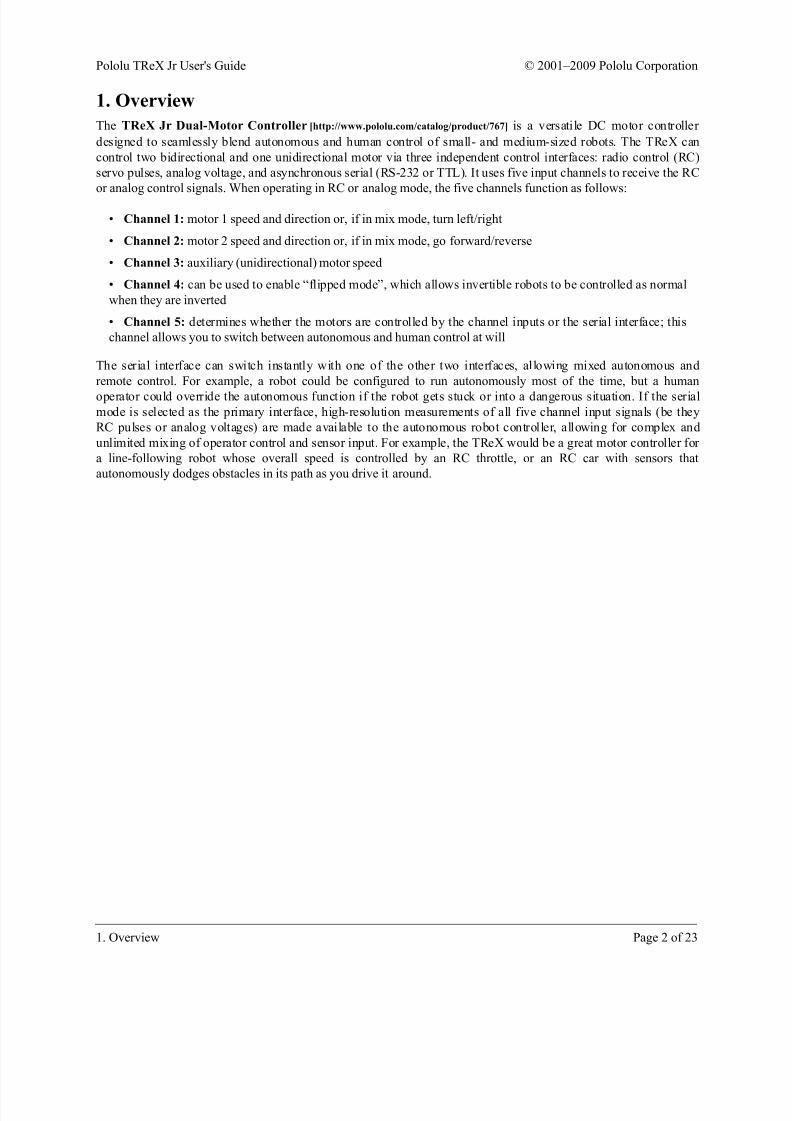
or analog control signals. When operating in RC or analog mode, the five channels function as follows:
• Channel 1: motor 1 speed and direction or, if in mix mode, turn left/right
• Channel 2: motor 2 speed and direction or, if in mix mode, go forward/reverse
• Channel 3: auxiliary (unidirectional) motor speed
• Channel 4: can be used to enable “flipped mode”, which allows invertible robots to be controlled as normal
when they are inverted
• Channel 5: determines whether the motors are controlled by the channel inputs or the serial interface; this
channel allows you to switch between autonomous and human control at will
The serial interface can switch instantly with one of the other two interfaces, allowing mixed autonomous and
remote control. For example, a robot could be configured to run autonomously most of the time, but a human
operator could override the autonomous function if the robot gets stuck or into a dangerous situation. If the serialmode is selected as the primary interface, high-resolution measurements of all five channel input signals (be they
RC pulses or analog voltages) are made available to the autonomous robot controller, allowing for complex and
unlimited mixing of operator control and sensor input. For example, the TReX would be a great motor controller for
a line-following robot whose overall speed is controlled by an RC throttle, or an RC car with sensors that
autonomously dodges obstacles in its path as you drive it around.
Pololu TReX Jr User's Guide © 2001–2009 Pololu Corporation
1. Overview Page 2 of 23

8/8/2019 TReX Jr Manual
http://slidepdf.com/reader/full/trex-jr-manual 3/23
2. Contacting Pololu
You can check the TReX Jr motor controller page [http://www.pololu.com/catalog/product/767] for additional
information. We would be delighted to hear from you about any of your projects and about your experience with the
TReX motor controller. You can contact us [http://www.pololu.com/contact] directly or post on our
forum [http://forum.pololu.com/]. Tell us what we did well, what we could improve, what you would like to see in the
future, or anything else you would like to say!
Pololu TReX Jr User's Guide © 2001–2009 Pololu Corporation
2. Contacting Pololu Page 3 of 23
8/8/2019 TReX Jr Manual
http://slidepdf.com/reader/full/trex-jr-manual 4/23
3. Getting Started
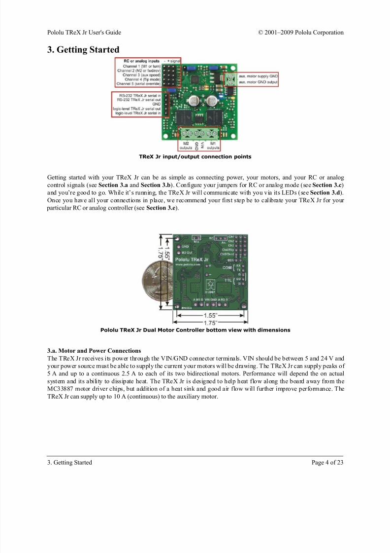
TReX Jr input/output connection points
Getting started with your TReX Jr can be as simple as connecting power, your motors, and your RC or analog
control signals (see Section 3.a and Section 3.b). Configure your jumpers for RC or analog mode (see Section 3.c)
and you’re good to go. While it’s running, the TReX Jr will communicate with you via its LEDs (see Section 3.d).Once you have all your connections in place, we recommend your first step be to calibrate your TReX Jr for your
particular RC or analog controller (see Section 3.e).
Pololu TReX Jr Dual Motor Controller bottom view with dimensions
3.a. Motor and Power Connections
The TReX Jr receives its power through the VIN/GND connector terminals. VIN should be between 5 and 24 V and
your power source must be able to supply the current your motors will be drawing. The TReX Jr can supply peaks of
5 A and up to a continuous 2.5 A to each of its two bidirectional motors. Performance will depend the on actual
system and its ability to dissipate heat. The TReX Jr is designed to help heat flow along the board away from the
MC33887 motor driver chips, but addition of a heat sink and good air flow will further improve performance. TheTReX Jr can supply up to 10 A (continuous) to the auxiliary motor.
Pololu TReX Jr User's Guide © 2001–2009 Pololu Corporation
3. Getting Started Page 4 of 23

8/8/2019 TReX Jr Manual
http://slidepdf.com/reader/full/trex-jr-manual 5/23
Note: The TReX Jr uses a linear voltage regulator to obtain its logic voltage (5-V Vcc). If you supply a
VIN of 24 V, your Vcc line will be limited to a maximum of 50 mA because of the regulator’s 1-W power
dissipation rating. This limitation might prevent your TReX Jr from being able to safely power an RC
receiver when VIN is so much higher than Vcc.
There are several different ways to connect motors to your TReX Jr:
Option 1:
TReX Jr motor connections (single battery)
The figure above demonstrates how to connect two bidirectional motors and a unidirectional auxiliary motor to your
TReX Jr, all powered by the same battery. Note that the auxiliary motor is driven by permanently connecting one
lead to power while the board PWMs the other lead between high impedance and ground. You must connect your
battery’s ground directly to the upper port of the auxiliary motor’s connection block if you plan to use the auxiliary
motor. Otherwise, the auxiliary motor could attempt to pull too much current through the TReX Jr itself, thereby
damaging the unit.
The auxiliary motor’s other lead connects to the lower port of its connection block. You will need to connect a diode
across the auxiliary motor’s terminals as shown below. Failing to do so will adversely affect the performance of
your TReX Jr and could result in permanent damage to the device. Take great care to ensure you do not solder the
diode in backwards! You should not solder a diode to your bidirectional motors.
You may find it beneficial to solder 0.1uF capacitors across all of your motors’ terminals. This will decrease the
noise put out by your motors and can improve performance of your TReX Jr. You can further decrease the noise put
out by your motors by keeping their leads as short as possible and twisting them around each other in a helix.
Option 2:
Pololu TReX Jr User's Guide © 2001–2009 Pololu Corporation
3. Getting Started Page 5 of 23
8/8/2019 TReX Jr Manual
http://slidepdf.com/reader/full/trex-jr-manual 6/23
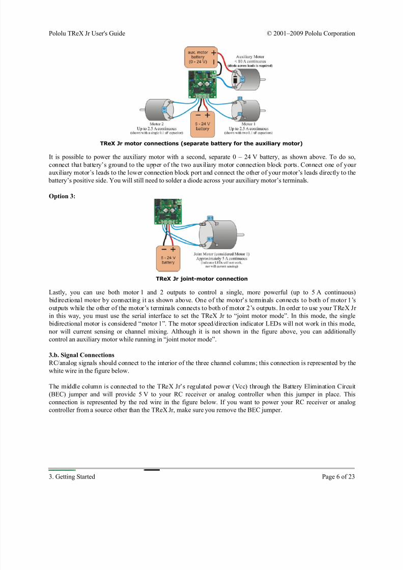
TReX Jr motor connections (separate battery for the auxiliary motor)
It is possible to power the auxiliary motor with a second, separate 0 – 24 V battery, as shown above. To do so,
connect that battery’s ground to the upper of the two auxiliary motor connection block ports. Connect one of your
auxiliary motor’s leads to the lower connection block port and connect the other of your motor’s leads directly to the
battery’s positive side. You will still need to solder a diode across your auxiliary motor’s terminals.
Option 3:
TReX Jr joint-motor connection
Lastly, you can use both motor 1 and 2 outputs to control a single, more powerful (up to 5 A continuous)
bidirectional motor by connecting it as shown above. One of the motor’s terminals connects to both of motor 1’soutputs while the other of the motor’s terminals connects to both of motor 2’s outputs. In order to use your TReX Jr
in this way, you must use the serial interface to set the TReX Jr to “joint motor mode”. In this mode, the single
bidirectional motor is considered “motor 1”. The motor speed/direction indicator LEDs will not work in this mode,
nor will current sensing or channel mixing. Although it is not shown in the figure above, you can additionally
control an auxiliary motor while running in “joint motor mode”.
3.b. Signal Connections
RC/analog signals should connect to the interior of the three channel columns; this connection is represented by the
white wire in the figure below.
The middle column is connected to the TReX Jr’s regulated power (Vcc) through the Battery Elimination Circuit
(BEC) jumper and will provide 5 V to your RC receiver or analog controller when this jumper in place. This
connection is represented by the red wire in the figure below. If you want to power your RC receiver or analog
controller from a source other than the TReX Jr, make sure you remove the BEC jumper.
Pololu TReX Jr User's Guide © 2001–2009 Pololu Corporation
3. Getting Started Page 6 of 23
8/8/2019 TReX Jr Manual
http://slidepdf.com/reader/full/trex-jr-manual 7/23
Warning: This middle Vcc column is tied to the output of a linear voltage regulator, so its current output
is limited by thermal dissipation. The regulator will only be able to safely supply a maximum of 100 mA
when VIN is 12 V and 50 mA when VIN is 24 V (it has a 1-W power dissipation rating). This is typically
sufficient for powering an analog joystick or RC receiver, but it is insufficient for powering servos. If you
want to connect servos to some of your RC receiver channels, you must power your RC receiver
separately and disconnect the BEC jumper. Attempting to use the TReX Jr’s regulated Vcc line to power
servos can permanently damage the TReX Jr.
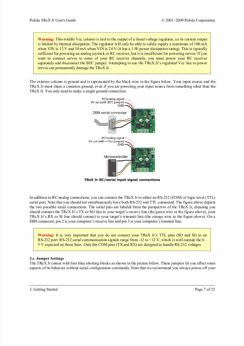
The exterior column is ground and is represented by the black wire in the figure below. Your input source and the
TReX Jr must share a common ground, even if you are powering your input source from something other than the
TReX Jr. You only need to make a single ground connection.
TReX Jr RC/serial input signal connections
In addition to RC/analog connections, you can connect the TReX Jr to either an RS-232 (COM) or logic-level (TTL)
serial port. Note that you should not simultaneously have both RS-232 and TTL connected. The figure above depicts
the two possible serial connections. The serial pins are labeled from the perspective of the TReX Jr, meaning you
should connect the TReX Jr’s TX or SO line to your target’s receive line (the green wire in the figure above); your
TReX Jr’s RX or SI line should connect to your target’s transmit line (the orange wire in the figure above). On a
DB9 connector, pin 2 is your computer’s receive line and pin 3 is your computer’s transmit line.
Warning: It is very important that you do not connect your TReX Jr’s TTL pins (SO and SI) to an
RS-232 port. RS-232 serial communication signals range from -12 to +12 V, which is well outside the 0 –
5 V expected on those lines. Only the COM pins (TX and RX) are designed to handle RS-232 voltages.
3.c. Jumper Settings
The TReX Jr comes with four blue shorting blocks as shown in the picture below. These jumpers let you affect some
aspects of its behavior without serial configuration commands. Note that we recommend you always power off your
Pololu TReX Jr User's Guide © 2001–2009 Pololu Corporation
3. Getting Started Page 7 of 23
8/8/2019 TReX Jr Manual
http://slidepdf.com/reader/full/trex-jr-manual 8/23
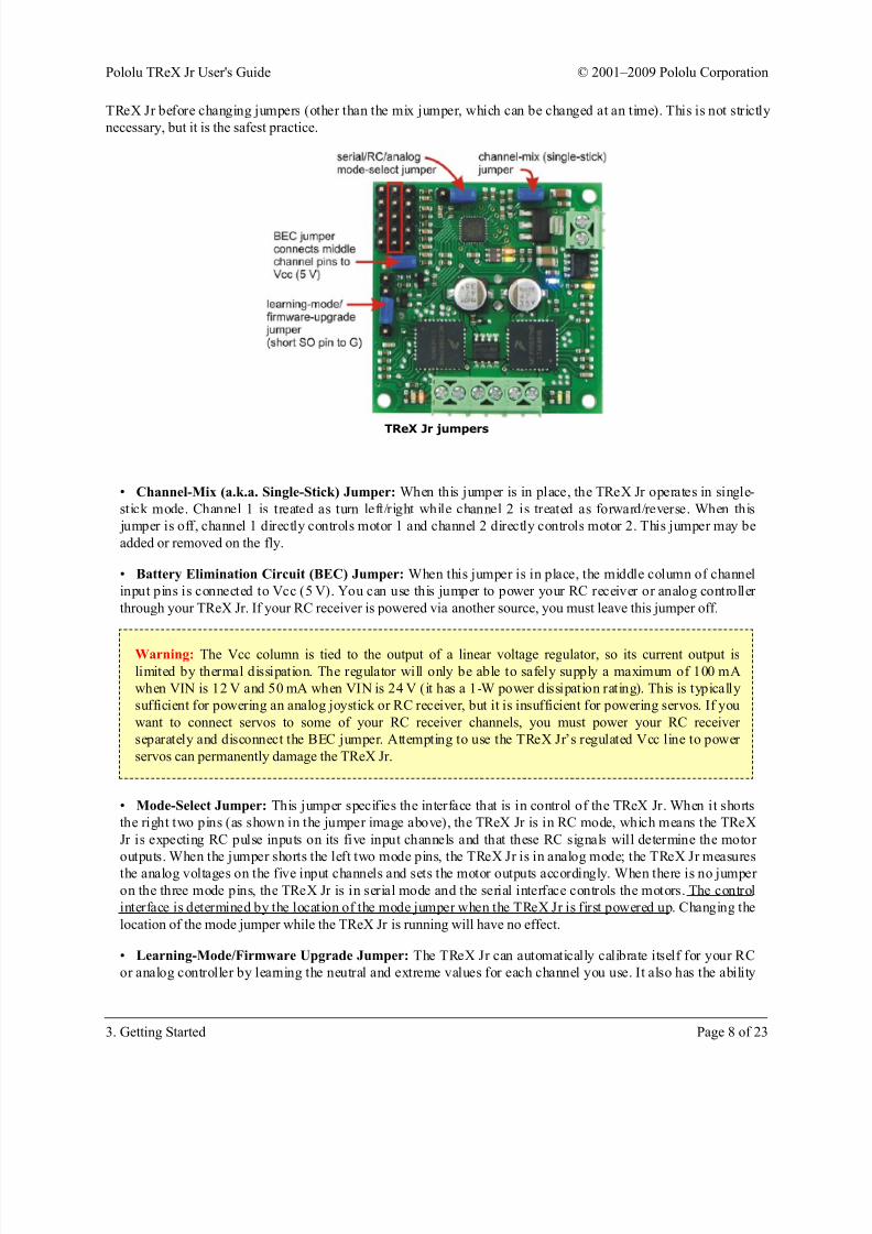
TReX Jr before changing jumpers (other than the mix jumper, which can be changed at an time). This is not strictly
necessary, but it is the safest practice.
TReX Jr jumpers
• Channel-Mix (a.k.a. Single-Stick) Jumper: When this jumper is in place, the TReX Jr operates in single-
stick mode. Channel 1 is treated as turn left/right while channel 2 is treated as forward/reverse. When this
jumper is off, channel 1 directly controls motor 1 and channel 2 directly controls motor 2. This jumper may be
added or removed on the fly.
• Battery Elimination Circuit (BEC) Jumper: When this jumper is in place, the middle column of channel
input pins is connected to Vcc (5 V). You can use this jumper to power your RC receiver or analog controller
through your TReX Jr. If your RC receiver is powered via another source, you must leave this jumper off.
Warning: The Vcc column is tied to the output of a linear voltage regulator, so its current output is
limited by thermal dissipation. The regulator will only be able to safely supply a maximum of 100 mA
when VIN is 12 V and 50 mA when VIN is 24 V (it has a 1-W power dissipation rating). This is typically
sufficient for powering an analog joystick or RC receiver, but it is insufficient for powering servos. If you
want to connect servos to some of your RC receiver channels, you must power your RC receiver
separately and disconnect the BEC jumper. Attempting to use the TReX Jr’s regulated Vcc line to power
servos can permanently damage the TReX Jr.
• Mode-Select Jumper: This jumper specifies the interface that is in control of the TReX Jr. When it shorts
the right two pins (as shown in the jumper image above), the TReX Jr is in RC mode, which means the TReX
Jr is expecting RC pulse inputs on its five input channels and that these RC signals will determine the motor
outputs. When the jumper shorts the left two mode pins, the TReX Jr is in analog mode; the TReX Jr measures
the analog voltages on the five input channels and sets the motor outputs accordingly. When there is no jumper
on the three mode pins, the TReX Jr is in serial mode and the serial interface controls the motors. The control
interface is determined by the location of the mode jumper when the TReX Jr is first powered up. Changing the
location of the mode jumper while the TReX Jr is running will have no effect.
• Learning-Mode/Firmware Upgrade Jumper: The TReX Jr can automatically calibrate itself for your RC
or analog controller by learning the neutral and extreme values for each channel you use. It also has the ability
Pololu TReX Jr User's Guide © 2001–2009 Pololu Corporation
3. Getting Started Page 8 of 23
8/8/2019 TReX Jr Manual
http://slidepdf.com/reader/full/trex-jr-manual 9/23
to upgrade its firmware. When placed across the SO and G pins, this jumper puts the TReX Jr into learning/
firmware-upgrade mode via the “secret handshake” (see Section 3.e). The TReX Jr ships with this jumper in
place since we recommend your first step be to calibrate for your controller. This jumper should be removed
before you begin normal operation.
Warning: You should never add this jumper while the board is powered! Disconnect power from the
board, add this jumper, and then reconnect power.
3.d. LED Feedback
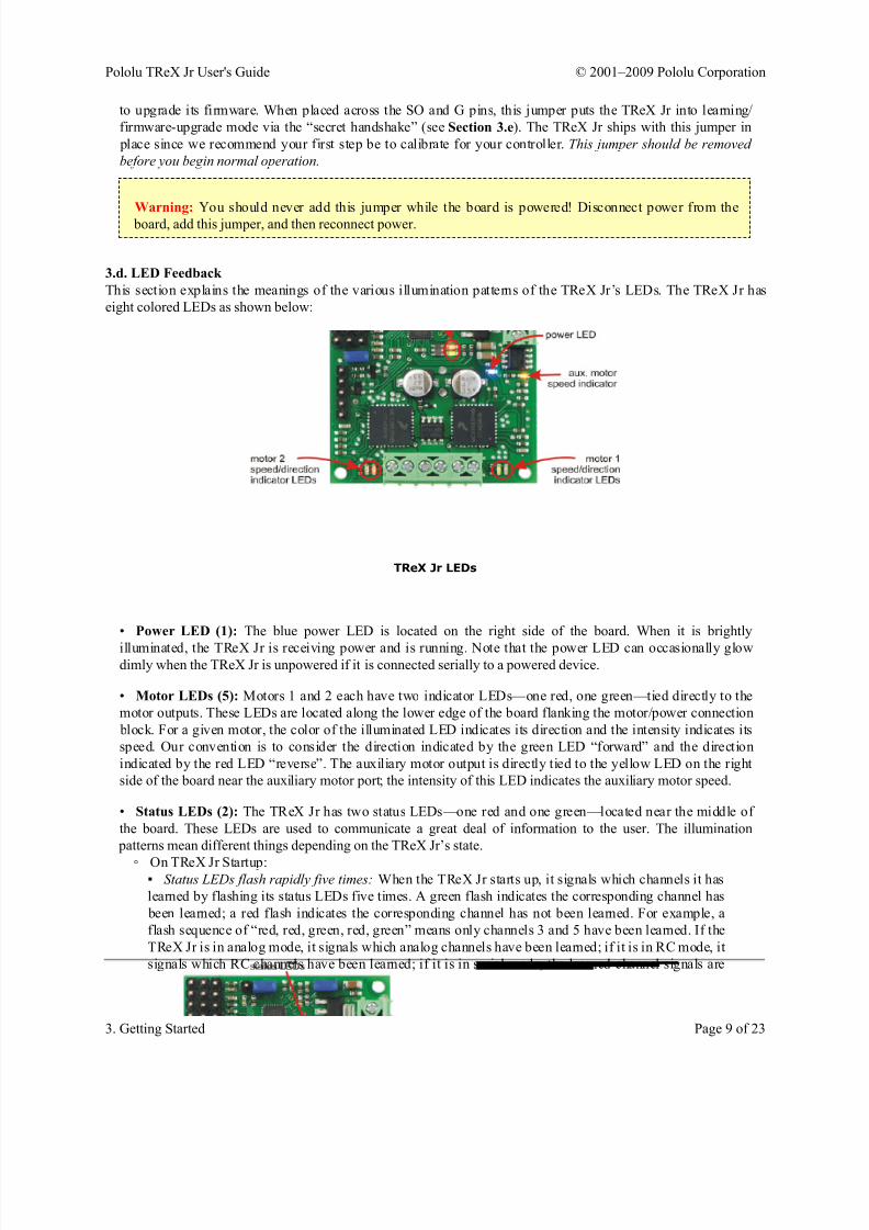
This section explains the meanings of the various illumination patterns of the TReX Jr’s LEDs. The TReX Jr has
eight colored LEDs as shown below:
TReX Jr LEDs
• Power LED (1): The blue power LED is located on the right side of the board. When it is brightly
illuminated, the TReX Jr is receiving power and is running. Note that the power LED can occasionally glowdimly when the TReX Jr is unpowered if it is connected serially to a powered device.
• Motor LEDs (5): Motors 1 and 2 each have two indicator LEDs—one red, one green—tied directly to the
motor outputs. These LEDs are located along the lower edge of the board flanking the motor/power connection
block. For a given motor, the color of the illuminated LED indicates its direction and the intensity indicates its
speed. Our convention is to consider the direction indicated by the green LED “forward” and the direction
indicated by the red LED “reverse”. The auxiliary motor output is directly tied to the yellow LED on the right
side of the board near the auxiliary motor port; the intensity of this LED indicates the auxiliary motor speed.
• Status LEDs (2): The TReX Jr has two status LEDs—one red and one green—located near the middle of
the board. These LEDs are used to communicate a great deal of information to the user. The illumination
patterns mean different things depending on the TReX Jr’s state.
◦ On TReX Jr Startup:▪ Status LEDs flash rapidly five times: When the TReX Jr starts up, it signals which channels it has
learned by flashing its status LEDs five times. A green flash indicates the corresponding channel has
been learned; a red flash indicates the corresponding channel has not been learned. For example, a
flash sequence of “red, red, green, red, green” means only channels 3 and 5 have been learned. If the
TReX Jr is in analog mode, it signals which analog channels have been learned; if it is in RC mode, it
signals which RC channels have been learned; if it is in serial mode, the learned-channel signals are
Pololu TReX Jr User's Guide © 2001–2009 Pololu Corporation
3. Getting Started Page 9 of 23
8/8/2019 TReX Jr Manual
http://slidepdf.com/reader/full/trex-jr-manual 10/23
for the mode selected by the “channel input source” parameter (this parameter’s default value is RC
mode).
▪ Red and green LEDs blink in unison around once per second: The TReX Jr is waiting to see if it
should enter learning mode. This happens when the TReX Jr is in RC or analog mode, the mix
jumper is in place, and the serial out (SO) pin is grounded. This last condition can arise if the TReX
Jr is connected serially to an unpowered microcontroller. Ungrounding the SO pin will cause the
TReX Jr to startup as normal; removing the mix jumper will put the TReX Jr into learning-mode, atwhich point it will either start trying to learn the channels or will wait for a valid signal on the input
lines. If it waits, it will flash the red and green LEDs in unison four times faster while waiting.
▪ Red and green LEDs alternate around once per second: The TReX Jr is waiting to see if it should
enter firmware-upgrade mode. This happens when the TReX Jr is in serial mode (i.e. there is no
mode jumper in place), the mix jumper is in place, and the serial out (SO) pin is grounded. This last
condition can arise if the TReX Jr is connected serially to an unpowered microcontroller.
Ungrounding the SO pin will cause the TReX Jr to startup as normal; removing the mix jumper will
put the TReX Jr into firmware-upgrade mode, which will cause the red and green LEDs to start
alternating four times faster.
◦ While Running Normally:
▪ Red LED on solid, green LED might flicker: The red LED solidly on indicates that serial is incontrol of the motors (i.e. serial override is active or the TReX Jr is in serial mode). While serial is in
control of the motors, the green LED acts as a serial-packet-received indicator. It lights when a
command byte is received and stays lit until the last byte of the command packet is received. The
flicker rate of the green LED will depend on the baud rate you’re using and the rate at which you’re
sending serial commands to the TReX Jr.
▪ Green LED on solid, red LED might flicker: The green LED solidly on indicates that the channel
inputs are in control of the motors (i.e. the TReX Jr is in RC or analog mode and serial override is not
active). While the channel inputs are in control of the motors, the red LED acts as a serial-packet-
received indicator. It lights when a command byte is received and stays lit until the last byte of the
command packet is received. The flicker rate of the red LED will depend on the baud rate you’re
using and the rate at which you’re sending serial commands to the TReX Jr.
▪ Green LED is rapidly flashing, red LED might flicker: The TReX Jr will not let the channel inputsstart controlling the motors until safe-start conditions are first met (see Section 4.e). Specifically, it is
waiting for a valid signal on all required channels, for the motor signals to request no motor
movement, and for the serial override signal to not be requesting serial override mode. This state
occurs when the TReX Jr first starts running in RC or analog mode, and can be retriggered if an RC
signal is ever lost on a required channel. This state will never occur if the TReX Jr is in serial mode.
While in this state, the red LED acts as a serial-packet-received indicator as described in the bullet
point above.
◦ While in Learning Mode (see Section 3.e):
▪ Red and green LEDs blinking rapidly in unison: The TReX Jr is in RC mode and it is waiting for a
valid RC signal on at least one channel before it begins learning the channel calibration values.
▪ Red LED on solid, green LED off: This is the first stage of the learning sequence in which the
TReX Jr is attempting to learn the neutral values of each channel. This phase should last around two
seconds. Do not touch the RC/analog sticks while the red LED is on or you could cause learning to
fail.
▪ Status LEDs flash rapidly five times: When the TReX Jr is through learning the neutral values, it
will flash the status LEDs five times to indicate which channels had neutrals successfully learned and
which channels failed neutral learning. A green flash indicates success for the corresponding channel;
a red flash indicates failure. If all five channels fail to learn neutral values, the learning process stops,
Pololu TReX Jr User's Guide © 2001–2009 Pololu Corporation
3. Getting Started Page 10 of 23
8/8/2019 TReX Jr Manual
http://slidepdf.com/reader/full/trex-jr-manual 11/23
otherwise it continues to the next phase, which is learning the values of the extremes. Once this last
learning phase is complete, the status LEDs will again flash five times to indicate whether the
corresponding channel was successfully learned. This final five-flash sequence will repeat until the
TReX Jr is reset.
▪ Red and green LEDs both on solid: This is the second and final stage of the learning sequence in
which the TReX Jr is attempting to learn the maximum and minimum values for each channel. This
phase lasts around ten seconds, during which time you should move the control sticks to their extremes. Make sure to hold each channel at each extreme for at least 0.5 seconds.
◦ While in Firmware-Upgrade Mode (see Section 6):
▪ Red and green LEDs alternate around once per second : The TReX Jr is waiting to see if it should
enter firmware-upgrade mode. This happens when the TReX Jr is in serial mode (i.e. there is no
mode jumper in place), the mix jumper is in place, and the serial out (SO) pin is grounded. This last
condition can arise if the TReX Jr is connected serially to an unpowered microcontroller.
Ungrounding the SO pin will cause the TReX Jr to startup as normal; removing the mix jumper will
put the TReX Jr into firmware-upgrade mode, which will cause the red and green LEDs to start
alternating four times faster.
▪ Red and green LEDs alternate around four times per second: The TReX Jr is in firmware-upgrade
mode and is waiting for the short between the serial out (SO) pin and ground to be removed.▪ Green LED flashes briefly once per second: The TReX Jr is in firmware-upgrade mode and is
waiting for the correct initial serial input sequence. The TReX Jr enters this state when the short
between the serial out (SO) pin and ground is removed after the mix jumper has been removed.
▪ Red LED flashes: There was a faulty input to the bootloader that has caused the bootloader to
revert to waiting for the correct initial serial input sequence. Note: once the firmware upload is
complete, the TReX Jr will reboot and the red LED may flash as part of the startup sequence. This is
not an indication of a firmware-update error. See the firmware-update section for further details.
▪ Green LED rapidly flashes: Everything is proceeding as expected during the firmware upgrade
process. Each successfully uploaded data packet causes the green LED to flash.
3.e. Automatic Calibration for Your RC/Analog Controller
The TReX Jr has the ability to automatically calibrate itself for your particular RC or analog controller. We stronglyrecommend you use this feature to calibrate your TReX Jr as it can result in a substantial increase in performance.
You only need to perform the calibration once, but you should recalibrate if you ever change controllers. The TReX
Jr can simultaneously store a set of analog calibration values and a set of RC calibration values; the calibration
values used depends on the mode of operation (or on the value of the “channel input source” parameter if the TReX
Jr is running in serial mode).
The TReX Jr calibrates itself by first learning the neutral values of all the channels and then learning the extremes.
You can enter learning mode via the secret handshake:
1. Power off your TReX Jr.
2. Connect your RC receiver or analog controller to your TReX Jr’s channel inputs.
3. Turn on your RC transmitter/analog controller. Set the sticks to the positions you would like to consider “neutral” and, if desired, zero your trim settings.
4. Attach the channel-mix jumper.
5. Attach the learning-mode jumper (i.e. short the serial out pin, SO, to ground, G). You must never attach
this jumper while the board is powered!
Pololu TReX Jr User's Guide © 2001–2009 Pololu Corporation
3. Getting Started Page 11 of 23
8/8/2019 TReX Jr Manual
http://slidepdf.com/reader/full/trex-jr-manual 12/23
6. Place the mode jumper to select for either RC or analog (whichever type of controller you’re trying to
calibrate for).
7. Restore power to your TReX Jr. You should see the red and green status LEDs blinking in unison around
once per second.
8. Remove the channel-mix jumper. If you now see the red and green status LEDs blinking together around
four times per second, the TReX Jr is unable to detect a valid RC pulse signal on any of its input channels. If instead you see the red LED turn on solid, you are now in learning mode, which proceeds in the following four
phases:
Learning mode phase 1: learning neutrals
While the red LED is on solid, the TReX Jr is attempting to learn the neutral values of all five channels. Do NOT
move the control sticks at all while the red LED is on. It should only take around two seconds for this first phase,
though it could be much shorter if the TReX Jr encounters problems learning the neutrals for all five channels. If any
RC pulse errors occur during the learning process or if the channel variance is too large, the TReX Jr will not learn
the channel.
Learning mode phase 2: neutral learning report
Once phase one is through, the TReX Jr will flash its status LEDs five times to indicate neutral-learning success or
failure for each channel. A green flash means that the neutral value was successfully learned for the correspondingchannel. A red flash means there was a problem and that channel will not be learned. For example, a flash pattern of
“red, red, green, red, green” means that neutrals were learned successfully for channels 3 and 5; channels 1, 2, and 4
will not be learned. If all five flashes are red, the learning process terminates here.
Learning mode phase 3: learning the extremes
This phase begins when both the red and green status LEDs light simultaneously and lasts approximately ten
seconds. During this time, the TReX Jr is attempting to determine the maximum and minimum values for each of the
five channels. You should try to hold each channel at each of its two extremes for at least half a second. Move the
control sticks around slowly and steadily. If you jerk them around very rapidly the TReX Jr may reject the channel
inputs as unreliable. If any RC pulse errors occur or if the channel variance isn’t large enough, the TReX Jr will not
learn the channel.
Learning mode phase 4: final learning reportThis phase is identical to phase 2, except here the green flashes represent channels that were fully learned. The
flashing pattern will repeat until the TReX Jr is reset. Now every time the TReX Jr starts up, it will quickly flash the
LEDs in this pattern to indicate which channels are calibrated and which are not.
Note: Once learning is complete, you should remove the learning-mode jumper and reset your TReX Jr.
Pololu TReX Jr User's Guide © 2001–2009 Pololu Corporation
3. Getting Started Page 12 of 23
8/8/2019 TReX Jr Manual
http://slidepdf.com/reader/full/trex-jr-manual 13/23
4. RC/Analog in Detail
This section provides a detailed overview of the RC and analog modes of operation. It explains how the TReX Jr
processes its channel inputs and how those inputs influence the TReX Jr when its in RC or analog mode.
4.a. Channel Functions
The five input channels along the left side of the TReX Jr accept either radio-controlled (RC) servo pulses or analog
voltages, depending on the position of the mode-selection jumper (or on the value of the “channel input source”
parameter if the TReX Jr is in serial mode). When not in serial mode, the TReX Jr acts on the five channels as
follows:
• Channel 1: If mix jumper is in place, turn left/right at the specified speed; if mix jumper is off, set motor 1
direction and speed.
• Channel 2: If mix jumper is in place, go forward/reverse at the specified speed; if mix jumper is off, set
motor 2 direction and speed.
• Channel 3: Set auxiliary motor speed (aux. motor is unidirectional).
• Channel 4: Enable/disable flipped mode. Flipped mode causes the TReX Jr to treat motor 1 as motor 2 (and
vice versa), and to swap its notions of forward and reverse for each motor. The result is that a differential-drive
robot will behave as normal when inverted if flipped mode is enabled. This channel acts like a switch that getsflipped when the channel value falls below a certain threshold. If your controller is not calibrated, this channel
may not function as intended.
• Channel 5: Enable/disable serial override. Serial override gives serial control of the motors for as long as
channel 5 enables it. When serial override is first enabled, each motor is set based on its most recently received
motor command, even if that command occurred while serial override was disabled. Channels 1, 2, and 3 will
not affect the motors while serial override is active (unless your serial control source is reading the values of
those channels and issuing its commands based in part on them). This channel acts like a switch that gets
flipped when the channel value falls below a certain threshold. If your controller is not calibrated, this channel
may not function as intended.
4.b. Channel Calibration
As was covered in Section 3.e, you can automatically calibrate your TReX Jr for your RC or analog controller. If
this doesn’t prove sufficient for your needs, you can manually calibrate your TReX Jr for your controller by
specifying the minimum, neutral, maximum, and deadband values for each channel. The TReX Jr can
simultaneously store both a set of RC and a set of analog calibration parameters. The calibration parameters are in
the units of the raw channel values: 0.4 us for RC, 4.89 mV for analog. In general, these parameters affect how the
TReX Jr interprets the channel input values.
Perhaps most noticeably, these parameters help determine how the channel inputs affect the motors. Motor speed is
scaled linearly (or parabolically, if the channel is set as parabolic using the “parabolic channels” configuration
parameter) from 0 at a channel input of neutral+deadband to max speed at a channel input of maximum. In the
other direction, motor speed goes from 0 at neutral-deadband to max speed at minimum. Motor speed is 0 for
channel inputs between neutral-deadband and neutral+deadband, and motor speed is at a maximum for channel
inputs greater than maximum or less than minimum. Motor direction is determined by the side of neutral the
channel input is on, and notions of forward and reverse can be switched on a channel by channel basis using the“reversed channels” configuration parameter.
4.c. General RC Information
When the channel inputs are RC servo pulses, the update rate of the channel values is determined by the pulse-train
frequency of your RC receiver. Typically this is 50 Hz (each channel updates every 20 ms). The TReX Jr can handle
channel pulse-train frequencies of 10 Hz to 125 Hz.
Pololu TReX Jr User's Guide © 2001–2009 Pololu Corporation
4. RC/Analog in Detail Page 13 of 23
8/8/2019 TReX Jr Manual
http://slidepdf.com/reader/full/trex-jr-manual 14/23
The TReX Jr measures the width of RC servo pulses with 12-bit resolution and an accuracy of 1 us. The raw channel
value is provided as a 12-bit number in units of 0.4 us, so a raw channel value of 2500 can be physically interpreted
as a pulse width of 2500×0.4 =1500 us. Servo pulse widths typically range from 1 ms to 2 ms, with a neutral value
of 1.5 ms. This would correspond to raw channel values of 2500, 5000, and 3750, respectively. The TReX Jr can
handle pulse widths as short as 0.5 ms (raw channel value 1250) and as long as 2.5 ms (raw channel value 6250). If
a channel reading is considered to be an error, the raw channel value will be 0xFFFF (65535 in decimal). Errors
result from pulse widths outside the acceptable range and from pulse trains with frequencies outside of theacceptable range. If a signal ceases on a channel, that channels value will stop updating until approximately 150 ms
elapse, at which point the channel’s raw value will become 0xFFFF. It will remain as such until valid signals are
once again detected on the line.
As a safety feature, you can designate channels as required using the “required channels” configuration parameter.
If a required channel goes for more than 500 ms without receiving a valid RC servo pulse and the TReX Jr is in RC
mode, the TReX Jr will enter safe-start mode (see Section 4.e). By default, the TReX Jr only requires channel one.
If you are not using all five channels, you can optionally ignore unused channels via the “ignored channels”
configuration parameter. Ignored channels are treated as fixed at their neutral values (no matter what signals their
lines receive).
4.d. General Analog InformationWhen the channel inputs are analog voltages, the update rate of the channel values is approximately 50 Hz (each
channel updates every 20 ms or so). Each channel’s value is the result of a 16-sample average of analog-to-digital
conversions.
The TReX Jr measures analog voltages with 10-bit resolution. The raw channel value is provided as a number
ranging from 0 to 1023, where 0 corresponds 0 V and 1023 corresponds to 5 V. Your channel source can be as
simple as the output of a potentiometer whose inputs are the channel’s associated power (make sure the BEC jumper
is in place) and ground connections.
Unlike with RC signals, the TReX Jr has no way of telling if a channel is receiving a valid analog signal. A
disconnected channel will still produce a result when run through the analog-to-digital converter. This poses two
potential problems:
1. If your analog signal source gets disconnected from your TReX Jr, the TReX Jr could drive the motors in
unexpected and potentially dangerous ways. Because of this, please be very careful when operating the TReX
Jr in analog mode.
2. Unused channels can impact behavior of the TReX Jr in undesirable ways. You may not plan on using the
flip or override channels, but leaving them disconnected could result in their floating to a value that would
enable flipped mode or serial override. One solution to this problem is to use the “ignored channels”
configuration parameter to set unused analog channels as ignored. The TReX Jr considers ignored channels to
be fixed at their neutral positions. An alternate, purely hardware-based solution would be to short any unused
motor channels to a used one and to tie any unused “enable” channels (4 or 5) to Vcc (the 5-volt line). By
shorting unused motor channels to a used one, you should be able to get past the safe-start portion of the
TReX’s start-up routine.
4.e. Safe-Start Mode
When the TReX Jr starts up in either RC or analog mode, it first enters safe-start mode. In this mode, the three
motors are shut down and are unaffected by the channel inputs. The TReX Jr lets you know its in this mode by
rapidly flashing its green status LED. To exit this mode, the following conditions must all be simultaneously met:
Pololu TReX Jr User's Guide © 2001–2009 Pololu Corporation
4. RC/Analog in Detail Page 14 of 23

8/8/2019 TReX Jr Manual
http://slidepdf.com/reader/full/trex-jr-manual 15/23
1. All required channels must have a valid signal. This only applies when the TReX Jr is in RC mode since
it’s not possible to have an invalid analog signal. Required channels are determined by the “required channels”
configuration parameter. Only channel one is required by default.
2. All motor channels must be close to their neutral values (i.e. they must not be instructing the motors to
move very quickly). Channel 5 must be disabling serial override. The TReX Jr will not allow you to start with
serial controlling the motors if you’re in RC or analog mode.
If you have floating channels while running in analog mode, it may be impossible for you to satisfy the safe-start
conditions. Bullet point #2 in the analog section (Section 4.d) provides several ways to fix this problem.
Once you have satisfied the safe-start conditions, the green status LED should stop flashing and turn solidly on. This
indicates that the channel inputs are now in control of the motors.
Pololu TReX Jr User's Guide © 2001–2009 Pololu Corporation
4. RC/Analog in Detail Page 15 of 23

8/8/2019 TReX Jr Manual
http://slidepdf.com/reader/full/trex-jr-manual 16/23
5. The Serial Interface
You can use the serial interface for four general purposes: querying the TReX Jr for information (any mode), setting
its configuration parameters (serial mode only), sending it motor commands (any mode), and upgrading its firmware
(must be in firmware-upgrade mode). Firmware upgrading is addressed in Section 6.
Serial motor commands are accepted in any mode, but they will only immediately affect the motors if the TReX Jr is
in serial mode or channel 5 has serial override active. When the TReX Jr is in RC or analog mode and serial override
is not active, the most recently received serial motor command for each motor is buffered. These buffered motor
commands take effect if serial override becomes active.
Note that when you are using the serial interface, it is crucial that you do not transmit to the TReX Jr while it is
transmitting to you. Because of the way the RS-232 circuit is tied to the logic-level serial lines, the TReX Jr can
sometimes get its transmissions echoed back to itself. It deals with this by ignoring its receive line while it is
transmitting, so anything you send it during this time will be lost. As a consequence, the TReX Jr will never transmit
anything over the serial line without your first explicitly asking it to. The high-level protocol for sending commands
that cause the TReX Jr to transmit data back to you should be as follows:
1. Transmit command packet that causes the TReX Jr to send data back to you
2. Wait for all the expected data to be received or for a reasonable timeout period
3. Transmit your next command packet
Motor commands are strictly one-way; the TReX Jr will not send data back in response to these. All other
commands result in two-way data transfer.
An additional consequence of the RS-232 circuit is everything you send to the TReX Jr using the RS-232
connection will be echoed back to you as you’re transmitting it (RS-232 transmit and receive lines are physically
tied together by a resistor). If you are connecting your TReX Jr to a COM port, you can either disable your receiver
while you transmit or you can simply discard the echoed bytes you know to expect. The command packet echo will
always arrive before any data the TReX Jr sends to you. Note that you will receive no echo if you use the logic level
(TTL) serial lines to communicate with the TReX Jr.
5.a. Serial Communication Settings
Unlike our other Pololu serial controllers, the TReX Jr does not support automatic baud detection. Instead, you can
configure the TReX Jr to run at one of 11 common baud rates ranging from 1200 to 115,200 bits per second. The
TReX Jr ships with a default baud rate of 19,200 bps.
The TReX Jr allows you to optionally select one of three different kinds of error detection to help you ensure the
integrity of your communications: even parity, odd parity, or 7-bit cyclic redundancy checking (CRC-7). Cyclic
redundancy checking is explained in more detail in Section 5.e. The default setting is no error detection.
Lastly, you can specify whether serial communication with the TReX Jr will use one or two stop bits. The default
setting is one stop bit.
These serial settings are controlled by a single “serial-settings” configuration parameter (see Section 5.d for moreinformation).
5.b. Serial Command Protocols
The TReX Jr serial command protocol is fairly straightforward. Communication is achieved by sending command
packets consisting of a single command byte followed by any data bytes that command requires. Command bytes
always have their most significant bits set (i.e. range from 128 – 255) while data bytes always have their most
Pololu TReX Jr User's Guide © 2001–2009 Pololu Corporation
5. The Serial Interface Page 16 of 23
8/8/2019 TReX Jr Manual
http://slidepdf.com/reader/full/trex-jr-manual 17/23
significant bits cleared (i.e. range from 0 – 127). This means that each data byte can only transmit seven bits of
information.
One significant improvement over other Pololu serial controllers is the TReX Jr’s ability to gracefully handle serial
errors (such as bad commands, incorrectly formatted commands, or even hardware-level serial errors). The TReX Jr
has a configuration parameter that, if set, will shut down the motors if a serial error occurs, but the TReX itself will
continue running and accepting commands. This is a safety precaution taken in case the serial error occurred duringa command that was intended to stop the motors.
The TReX Jr will respond to two sub-protocols:
Compact Protocol:
This is the simpler and more compact of the two protocols; it is the protocol you should use if your TReX Jr is the
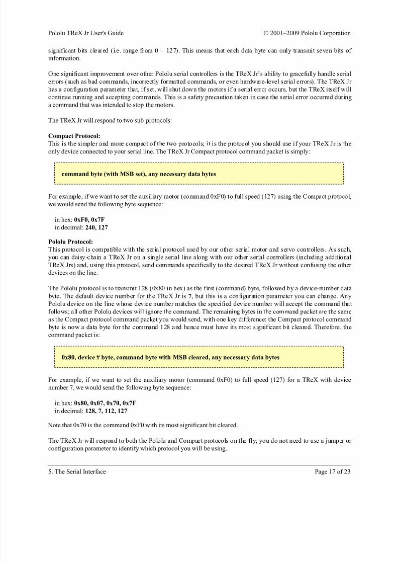
only device connected to your serial line. The TReX Jr Compact protocol command packet is simply:
command byte (with MSB set), any necessary data bytes
For example, if we want to set the auxiliary motor (command 0xF0) to full speed (127) using the Compact protocol,we would send the following byte sequence:
in hex: 0xF0, 0x7F
in decimal: 240, 127
Pololu Protocol:
This protocol is compatible with the serial protocol used by our other serial motor and servo controllers. As such,
you can daisy-chain a TReX Jr on a single serial line along with our other serial controllers (including additional
TReX Jrs) and, using this protocol, send commands specifically to the desired TReX Jr without confusing the other
devices on the line.
The Pololu protocol is to transmit 128 (0x80 in hex) as the first (command) byte, followed by a device-number data
byte. The default device number for the TReX Jr is 7, but this is a configuration parameter you can change. AnyPololu device on the line whose device number matches the specified device number will accept the command that
follows; all other Pololu devices will ignore the command. The remaining bytes in the command packet are the same
as the Compact protocol command packet you would send, with one key difference: the Compact protocol command
byte is now a data byte for the command 128 and hence must have its most significant bit cleared. Therefore, the
command packet is:
0x80, device # byte, command byte with MSB cleared, any necessary data bytes
For example, if we want to set the auxiliary motor (command 0xF0) to full speed (127) for a TReX with device
number 7, we would send the following byte sequence:
in hex: 0x80, 0x07, 0x70, 0x7F
in decimal: 128, 7, 112, 127
Note that 0x70 is the command 0xF0 with its most significant bit cleared.
The TReX Jr will respond to both the Pololu and Compact protocols on the fly; you do not need to use a jumper or
configuration parameter to identify which protocol you will be using.
Pololu TReX Jr User's Guide © 2001–2009 Pololu Corporation
5. The Serial Interface Page 17 of 23
8/8/2019 TReX Jr Manual
http://slidepdf.com/reader/full/trex-jr-manual 18/23
5.c. Serial Command List and Documentation
The TReX Jr command documentation [http://www.pololu.com/file/download/TReXJr_Commands_v1.0.pdf?file_id=0J12]
(100k pdf) contains a list of all the serial commands the TReX Jr recognizes along with detailed documentation.
5.d. Configuration Parameter List and Documentation
The TReX Jr parameter documentation [http://www.pololu.com/file/download/TReXJr_Parameters_v1.0.pdf?file_id=0J13]
(124k pdf) contains a list of all the TReX Jr’s configuration parameters along with detailed documentation.
5.e. Cyclic Redundancy Check (CRC) Error Detection
For certain applications, verifying the integrity of the data you’re sending and receiving can be very important.
Because of this, the TReX Jr has optional 7-bit cyclic redundancy checking, which is similar to a standard checksum
but somewhat more robust as it can detect duplicated and out-of-order bytes.
When bit 6 of the serial settings parameter is cleared and bit 5 is set, cyclic redundancy checking is enabled. In CRC
mode, the TReX Jr expects an extra byte to be tacked onto the end of every command packet. The lower seven bits
of this byte must be the 7-bit CRC for that packet, or else the TReX Jr will set its CRC Error bit in the UART Error
Byte and ignore the command. The TReX Jr will also transmit an additional byte every time it returns data; the
lower seven bits of this byte will be the 7-bit CRC for the packet of data the TReX Jr is sending you.
A detailed account of how cyclic redundancy checking works is beyond the scope of this document, but you can finda wealth of information using Wikipedia [http://en.wikipedia.org/wiki/Cyclic_redundancy_check]. The quick version is that
a CRC computation is basically a carryless long division of a CRC “polynomial” into your message, where all you
care about is the remainder. The TReX Jr uses CRC-7, which means it uses an 8-bit polynomial (whose MSB must
always be 1) and, as a result, produces a 7-bit remainder. This remainder is the lower 7 bits of the CRC byte you
tack onto the end of your command packets.
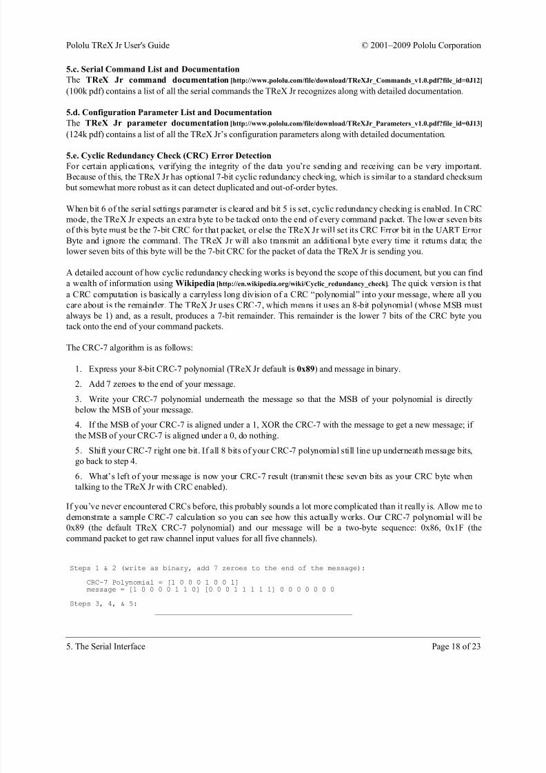
The CRC-7 algorithm is as follows:
1. Express your 8-bit CRC-7 polynomial (TReX Jr default is 0x89) and message in binary.
2. Add 7 zeroes to the end of your message.
3. Write your CRC-7 polynomial underneath the message so that the MSB of your polynomial is directly
below the MSB of your message.
4. If the MSB of your CRC-7 is aligned under a 1, XOR the CRC-7 with the message to get a new message; if
the MSB of your CRC-7 is aligned under a 0, do nothing.
5. Shift your CRC-7 right one bit. If all 8 bits of your CRC-7 polynomial still line up underneath message bits,
go back to step 4.
6. What’s left of your message is now your CRC-7 result (transmit these seven bits as your CRC byte when
talking to the TReX Jr with CRC enabled).
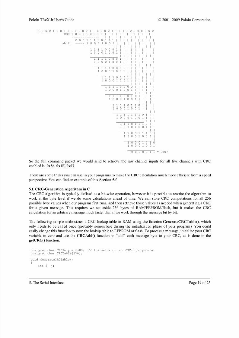
If you’ve never encountered CRCs before, this probably sounds a lot more complicated than it really is. Allow me to
demonstrate a sample CRC-7 calculation so you can see how this actually works. Our CRC-7 polynomial will be
0x89 (the default TReX CRC-7 polynomial) and our message will be a two-byte sequence: 0x86, 0x1F (the
command packet to get raw channel input values for all five channels).
Steps 1 & 2 (write as binary, add 7 zeroes to the end of the message):
CRC-7 Polynomial = [1 0 0 0 1 0 0 1]message = [1 0 0 0 0 1 1 0] [0 0 0 1 1 1 1 1] 0 0 0 0 0 0 0
Steps 3, 4, & 5:_______________________________________________
Pololu TReX Jr User's Guide © 2001–2009 Pololu Corporation
5. The Serial Interface Page 18 of 23
8/8/2019 TReX Jr Manual
http://slidepdf.com/reader/full/trex-jr-manual 19/23
1 0 0 0 1 0 0 1 ) 1 0 0 0 0 1 1 0 0 0 0 1 1 1 1 1 0 0 0 0 0 0 0XOR 1 0 0 0 1 0 0 1 | | | | | | | | | | | | | | |
--------------- | | | | | | | | | | | | | | |0 0 0 1 1 1 1 0 0 0 1 | | | | | | | | | | |
shift ----> 1 0 0 0 1 0 0 1 | | | | | | | | | | |_______________ | | | | | | | | | | |1 1 1 1 0 0 0 1 | | | | | | | | | |1 0 0 0 1 0 0 1 | | | | | | | | | |_______________ | | | | | | | | | |
1 1 1 1 0 0 0 1 | | | | | | | | |1 0 0 0 1 0 0 1 | | | | | | | | |_______________ | | | | | | | | |1 1 1 1 0 0 0 1 | | | | | | | |1 0 0 0 1 0 0 1 | | | | | | | |_______________ | | | | | | | |1 1 1 1 0 0 0 1 | | | | | | |1 0 0 0 1 0 0 1 | | | | | | |_______________ | | | | | | |1 1 1 1 0 0 0 0 | | | | | |1 0 0 0 1 0 0 1 | | | | | |_______________ | | | | | |1 1 1 1 0 0 1 0 | | | | |1 0 0 0 1 0 0 1 | | | | |_______________ | | | | |1 1 1 1 0 1 1 0 | | | |1 0 0 0 1 0 0 1 | | | |_______________ | | | |1 1 1 1 1 1 1 0 | | |
1 0 0 0 1 0 0 1 | | |_______________ | | |1 1 1 0 1 1 1 0 | |1 0 0 0 1 0 0 1 | |_______________ | |1 1 0 0 1 1 1 0 |1 0 0 0 1 0 0 1 |_______________ |1 0 0 0 1 1 1 01 0 0 0 1 0 0 1_______________0 0 0 0 1 1 1 = 0x07
So the full command packet we would send to retrieve the raw channel inputs for all five channels with CRC
enabled is: 0x86, 0x1F, 0x07
There are some tricks you can use in your programs to make the CRC calculation much more efficient from a speed
perspective. You can find an example of this Section 5.f .
5.f. CRC-Generation Algorithm in C
The CRC algorithm is typically defined as a bit-wise operation, however it is possible to rewrite the algorithm to
work at the byte level if we do some calculations ahead of time. We can store CRC computations for all 256
possible byte values when our program first runs, and then retrieve those values as needed when generating a CRC
for a given message. This requires we set aside 256 bytes of RAM/EEPROM/flash, but it makes the CRC
calculation for an arbitrary message much faster than if we work through the message bit by bit.
The following sample code stores a CRC lookup table in RAM using the function GenerateCRCTable(), which
only needs to be called once (probably somewhere during the initialization phase of your program). You could
easily change this function to store the lookup table to EEPROM or flash. To process a message, initialize your CRC
variable to zero and use the CRCAdd() function to “add” each message byte to your CRC, as is done in thegetCRC() function.
unsigned char CRCPoly = 0x89; // the value of our CRC-7 polynomialunsigned char CRCTable[256];
void GenerateCRCTable(){
int i, j;
Pololu TReX Jr User's Guide © 2001–2009 Pololu Corporation
5. The Serial Interface Page 19 of 23

8/8/2019 TReX Jr Manual
http://slidepdf.com/reader/full/trex-jr-manual 20/23
// generate a table value for all 256 possible byte valuesfor (i = 0; i < 256; i++){
CRCTable[i] = (i & 0x80) ? i ^ CRCPoly : i;for (j = 1; j < 8; j++){
CRCTable[i] <<= 1;if (CRCTable[i] & 0x80)
CRCTable[i] ^= CRCPoly;
}}}
// adds a message byte to the current CRC-7 to get a the new CRC-7unsigned char CRCAdd(unsigned char CRC, unsigned char message_byte){
return CRCTable[(CRC << 1) ^ message_byte];}
// returns the CRC-7 for a message of "length" bytesunsigned char getCRC(unsigned char message[], int length){
int i;unsigned char CRC = 0;
for (i = 0; i < length; i++)CRC = CRCAdd(CRC, message[i]);
return CRC;}
5.g. Resetting the Serial Communication Parameters
It is possible to reset the TReX Jr to its default serial settings using the following jumper sequence:
1. Power off your TReX Jr.
2. Attach the channel-mix jumper.
3. Attach the learning-mode/firmware-update jumper (i.e. short SO (Serial Out ) pin to G (Ground)).
4. Remove the mode-selection jumper (i.e. set the TReX Jr for Serial Mode).
5. Restore power to your TReX Jr. You should see the red and green status LEDs alternating around once per
second.
6. Remove the channel-mix jumper. You should now see the red and green status LEDs alternating around
four times per second.
7. Power off your TReX Jr.
When you next power up your TReX Jr, its serial settings will be back to their default values: 19.2 kbps baud, 1
stop bit, no error detection
Pololu TReX Jr User's Guide © 2001–2009 Pololu Corporation
5. The Serial Interface Page 20 of 23
8/8/2019 TReX Jr Manual
http://slidepdf.com/reader/full/trex-jr-manual 21/23
6. Updating the TReX Jr's Firmware
Current Firmware Versions
• Our most recently released firmware update for the TReX Jr motor controller is
trexjrv1_2.trx [http://www.pololu.com/file/download/trexjrv1_2.trx?file_id=0J238](161k trx) (version 1.2). This version
fixes a bug that prevented baud rates of 38.4 and 28.8 kbps from working in versions 1.0 and 1.1. All other
supported baud rates work properly in firmware versions 1.0 and 1.1, so if your TReX Jr does not have version
1.2 firmware and you do not need communicate serially at 38,400 or 28,800 bps, you do not need to update
your firmware to 1.2. Version 1.2 also adds a new configuration parameter that lets you optionally delay the
TReX Jr’s serial responses by 1ms so that slower microcontrollers, such as the Basic Stamp, won’t miss the
first byte of the TReX Jr’s response. Previously, if you wanted such a delay, you needed to use firmware
version 1.1; if you didn’t want this delay, you needed to use firmware version 1.0. Please note that you should
upgrade your TReX Configurator [http://www.pololu.com/file/download/
TReXConfiguratorInstaller_090923.zip?file_id=0J236] (294k zip) to version 090923 or later prior to updating your
firmware to version 1.2. If you have an older version of the TReX Configurator installed, you should manually
uninstall it first using the Add/Remove Programs control panel.
• The firmware that comes preloaded on every TReX Jr motor controller is
trexjrv1_0.trx [http://www.pololu.com/file/download/trexjrv1_0.trx?file_id=0J91](137k trx).
• We have released an alternate firmware version: trexjrv1_1.trx [http://www.pololu.com/file/download/
trexjrv1_1.trx?file_id=0J92] (138k trx). Please note that this alternate version is not considered an upgrade over
the original version 1.0. Rather, version 1.1 exists to improve serial communication with controllers that require
a delay between transmitting and receiving, such as the Basic Stamp. Firmware version 1.1 inserts a 1 ms delay
between the last byte of a received command packet and the first byte of the TReX Jr’s transmitted response,
which should give your controller enough time to switch from serial-out mode to serial-in mode. Without this
delay, some slower controllers will miss the first byte of the TReX Jr’s response, especially if you are
communicating at higher baud rates. If your controller can simultaneously transmit and receive, or if it does not
take much time to switch between serial-out and serial-in mode, you should use firmware version 1.0 as this
will increase the rate at which you can communicate with and control your TReX Jr.
Updating Firmware
To update the firmware, you need to put your TReX Jr into firmware-update mode and then send the new binaryfirmware file, which you can do using the TReX Configurator program [http://www.pololu.com/file/download/
TReXConfiguratorInstaller_090923.zip?file_id=0J236] (294k zip) or a terminal program. We recommend you read through
the following procedure before performing the update.
1. Turn off power to your TReX Jr.
2. Put the TReX Jr into Serial Mode by removing the Mode jumper.
3. Ground the TTL Serial Out (SO) pin by attaching the Learning-Mode/Firmware-Upgrade jumper.
4. Attach the Mix jumper.
5. Restore power to the TReX Jr; the status LEDs should alternately flash red and green.
6. Remove the Mix jumper; the status LEDs should alternate faster.
7. Remove the Learning-Mode/Firmware-Upgrade jumper; the green status LED should now briefly flash
every second.
8. Reconnect your TReX Jr’s serial cable to establish a connection between your TReX Jr and your computer.
Pololu TReX Jr User's Guide © 2001–2009 Pololu Corporation
6. Updating the TReX Jr's Firmware Page 21 of 23
8/8/2019 TReX Jr Manual
http://slidepdf.com/reader/full/trex-jr-manual 22/23
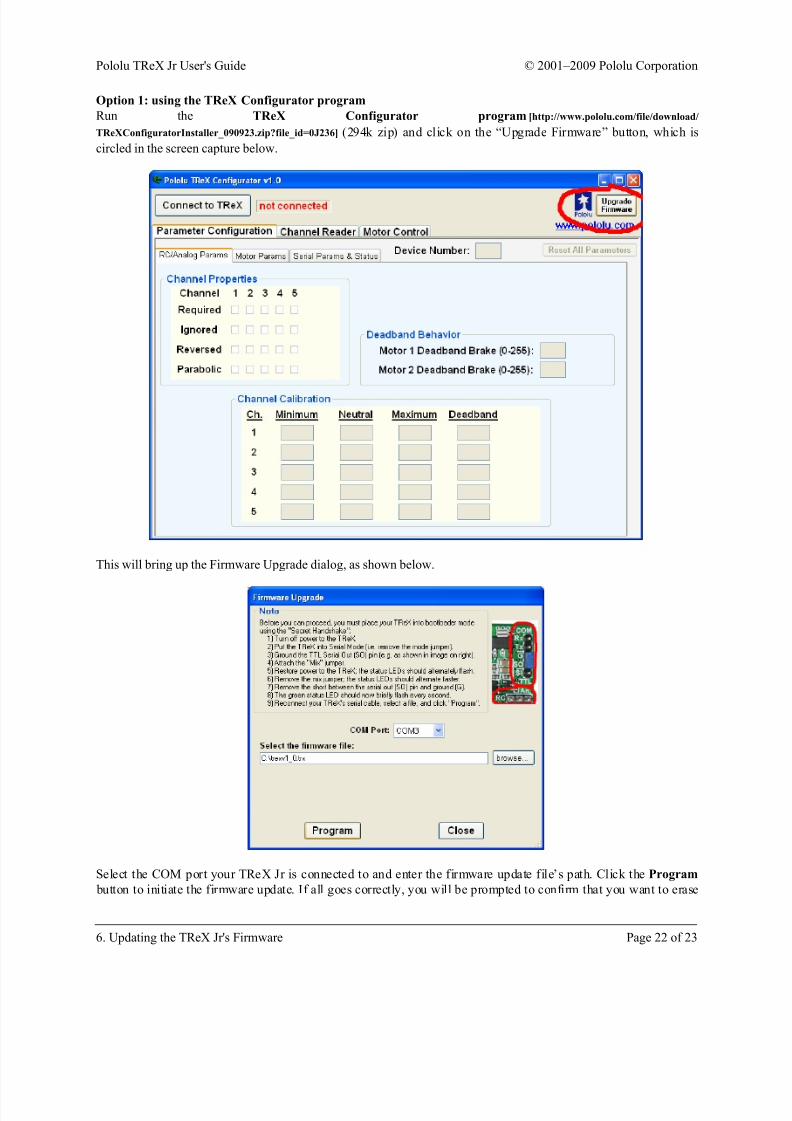
Option 1: using the TReX Configurator program
Run the TReX Configurator program [http://www.pololu.com/file/download/
TReXConfiguratorInstaller_090923.zip?file_id=0J236] (294k zip) and click on the “Upgrade Firmware” button, which is
circled in the screen capture below.
This will bring up the Firmware Upgrade dialog, as shown below.
Select the COM port your TReX Jr is connected to and enter the firmware update file’s path. Click the Program
button to initiate the firmware update. If all goes correctly, you will be prompted to confirm that you want to erase
Pololu TReX Jr User's Guide © 2001–2009 Pololu Corporation
6. Updating the TReX Jr's Firmware Page 22 of 23

8/8/2019 TReX Jr Manual
http://slidepdf.com/reader/full/trex-jr-manual 23/23
your current firmware and you will then see a progress bar showing you the status of the upload. If no errors occur,
you will see a success message when the update is finished.
Option 2: using a terminal program
If you would rather use a terminal program, you will need one that is capable of transferring binary files, such as
Tera Term Pro. Connect to the serial port that your TReX Jr is on at 115.2 kbsp with 8-bit characters, no parity, and
one stop bit. No flow control is necessary. If you have completed the 8 steps above (so that the green status LED isflashing once per second), you are ready to upload the new firmware file. First, transmit the character ’s’. This will
erase the current firmware. Next, transfer the firmware update file (.trx) to the TReX Jr as a binary file. If
everything works correctly you should see a ’*’ appear and the TReX Jr’s red status LED will flash five times as it
starts up before staying solidly on.
Pololu TReX Jr User's Guide © 2001–2009 Pololu Corporation
6. Updating the TReX Jr's Firmware Page 23 of 23