trend-10-15-lnx 2016-10-01 englisch - start | … · · 2018-01-04ttl-trend -10/15/lnx energy...
TRANSCRIPT
T T L - TREND -10 /15 / LNXEne r g y s a v i n g a i r c u r t a i n s y s t ems
w i t h EC- f an t e chno l og y
Comfort
TTL Products
TTL-TREND | Door air curtain - against cold and draft with proven technology
TTL air curtain systems guarantee high functionality and
a quality that has been tested against standards.
Using innovative technology, outstanding design and
a wide programm suitable for all applications, TTL is a
fi rst class reference with respect to climate separation
and energy savings at doors and gates.
Modern sales psychology relies today on generous ar-
chitecture, also and especially in the doors area. Shop-
ping today is an adventure, this includes feeling good
- not only for the customer but also for the personnel.
TTL-TREND
– the energy saving air curtain for
open doors, gates and passages.
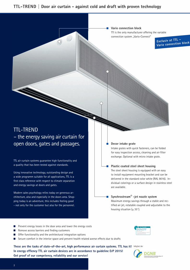
Vario connection block
TTl is the only manufacturer offering the variable
connection system „Vario-Connect“
2
Exclusiv at TTL –
Vario connection block
Prevent energy losses in the door area and lower the energy costs
Remove access barriers and fi nding customers
Offer functionality and the architectural integration options
Secure comfort in the interior space and prevent health related averse effects due to drafts
These are the tasks of state-of-the-art, high performance air curtain systems. TTL has it!
In energy effi ency TTL air curtain devices are in accordance to guideline ErP 2015!
Get proof of our competency, reliability and our service!
Synchrostream® -jet nozzle system
Maximum energy savings through a stable and rec-
tifi ed air jet, rotatable coupled and adjustable to the
housing situation (± 35°).
Plastic coated steel sheet housing
The steel sheet housing is equipped with an easy
to install equipment mounting bracket and can be
delivered in the standard color white (RAL 9016). In-
dividual colorings or a surface design in stainless steel
are available.
Decor intake grate
Intake grates with quick fasteners, can be folded
for easy inspection access, cleaning and air fi lter
exchange. Optional with micro intake grate.
Effi cie
ntly co
mbined
and s
ave up
to 55% en
ergy!
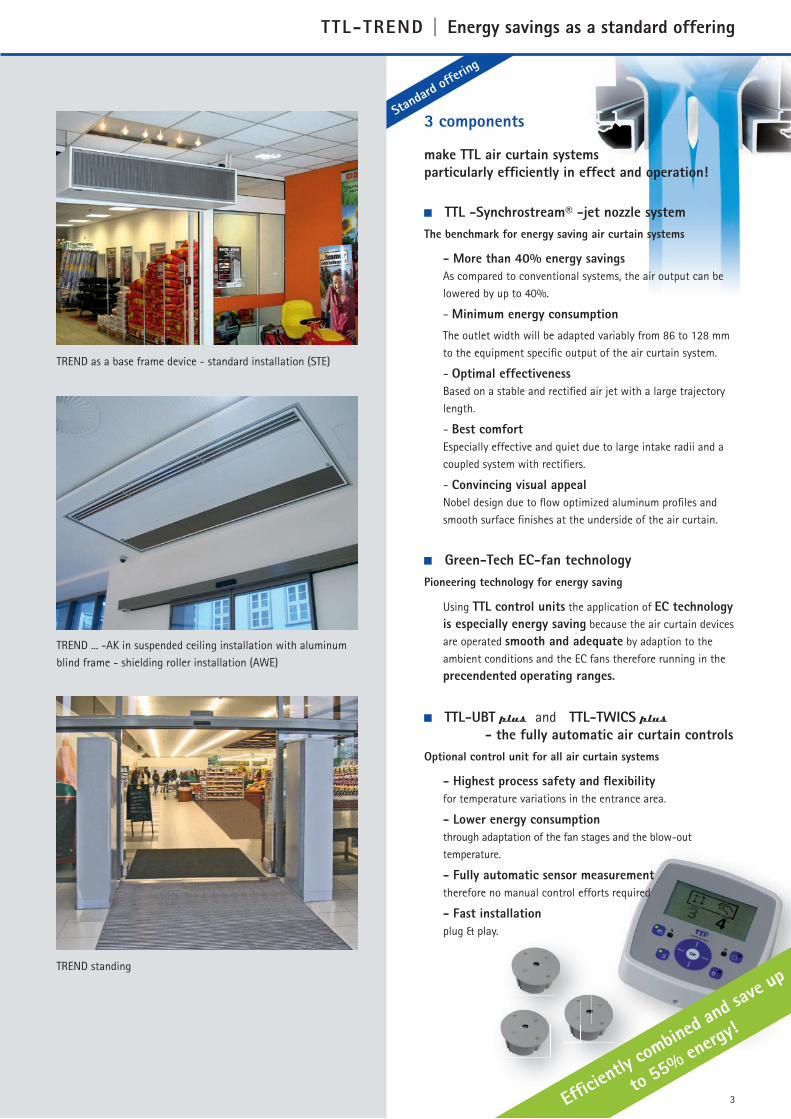
TREND as a base frame device - standard installation (STE)
TREND ... -AK in suspended ceiling installation with aluminum
blind frame - shielding roller installation (AWE)
TREND standing
3
Standa
rd off
ering
TTL-TREND | Energy savings as a standard offering
TTL-UBT plus and TTL-TWICS plus
- the fully automatic air curtain controls
Optional control unit for all air curtain systems
- Highest process safety and fl exibility
for temperature variations in the entrance area.
- Lower energy consumption
through adaptation of the fan stages and the blow-out
temperature.
- Fully automatic sensor measurement
therefore no manual control efforts required
- Fast installation
plug & play.
TTL -Synchrostream® -jet nozzle system
The benchmark for energy saving air curtain systems
- More than 40% energy savings
As compared to conventional systems, the air output can be
lowered by up to 40%.
- Minimum energy consumption
The outlet width will be adapted variably from 86 to 128 mm
to the equipment specifi c output of the air curtain system.
- Optimal effectiveness
Based on a stable and rectifi ed air jet with a large trajectory
length.
- Best comfort
Especially effective and quiet due to large intake radii and a
coupled system with rectifi ers.
- Convincing visual appeal
Nobel design due to fl ow optimized aluminum profi les and
smooth surface fi nishes at the underside of the air curtain.
Green-Tech EC-fan technology
Pioneering technology for energy saving
Using TTL control units the application of EC technology
is especially energy saving because the air curtain devices
are operated smooth and adequate by adaption to the
ambient conditions and the EC fans therefore running in the
precendented operating ranges.
3 components
make TTL air curtain systems
particularly effi ciently in effect and operation!
35°35°
TTL-TREND | Confi guration
System designEquipment shape Comfort: Neutral housing
shape made from plastic coated paneling
sheets, standard color white (RAL 9016).
Easy and installation friendly mounting
using rivet nuts M8 at the upper side of the
device.
IntakeDecor intake grates, powder coated RAL
9006 with slit holes and integrated rege-
nerative G2 hoard foam fi lter plate or low
maintenance, fi lterless micro-intake grate,
can be opened and closed without tools
through self latching „TTL-easy-klick“ quick
fasteners.
FansIn Green-Tech EC technology
- energy saving and high effi ciently
(information see: www.ec-luftschleier.de),
Single monitored with pulse tachometer
signal and single motor protection per fan.
Low-vibration and noise reduced, durable,
maintenance free, in robust and conso-
lidated design, Contact protection with
CE-compliant fan safety screen.
Heat exchangerFor PWW as a wide band low temperature
heat exchanger made from Cu/Al with spe-
cial lamella for optimum heat transfer, heat
connection selectable at the top or the side
through Vario-Connect connection.
Max. rated pressure PN 16 bar at 110 °C.
For steam or hot water in stainless steel/
steel, zinc plated. For electric heating as
fi nned tube heat register including safety
circuit.
Electrical connectionThe power supply is provided by an internal
terminal block. Control devices are contacted
with a ready-made data line or with a re-
clamping adapter via uniform bus connectors.
The electronic connection and control board
in the air curtain offer additional control
and programming options, connection and
control accesses for the building control
system as well as external contact sensors for
automatic modes and for the actuation of the
solenoid valve and/or pump.
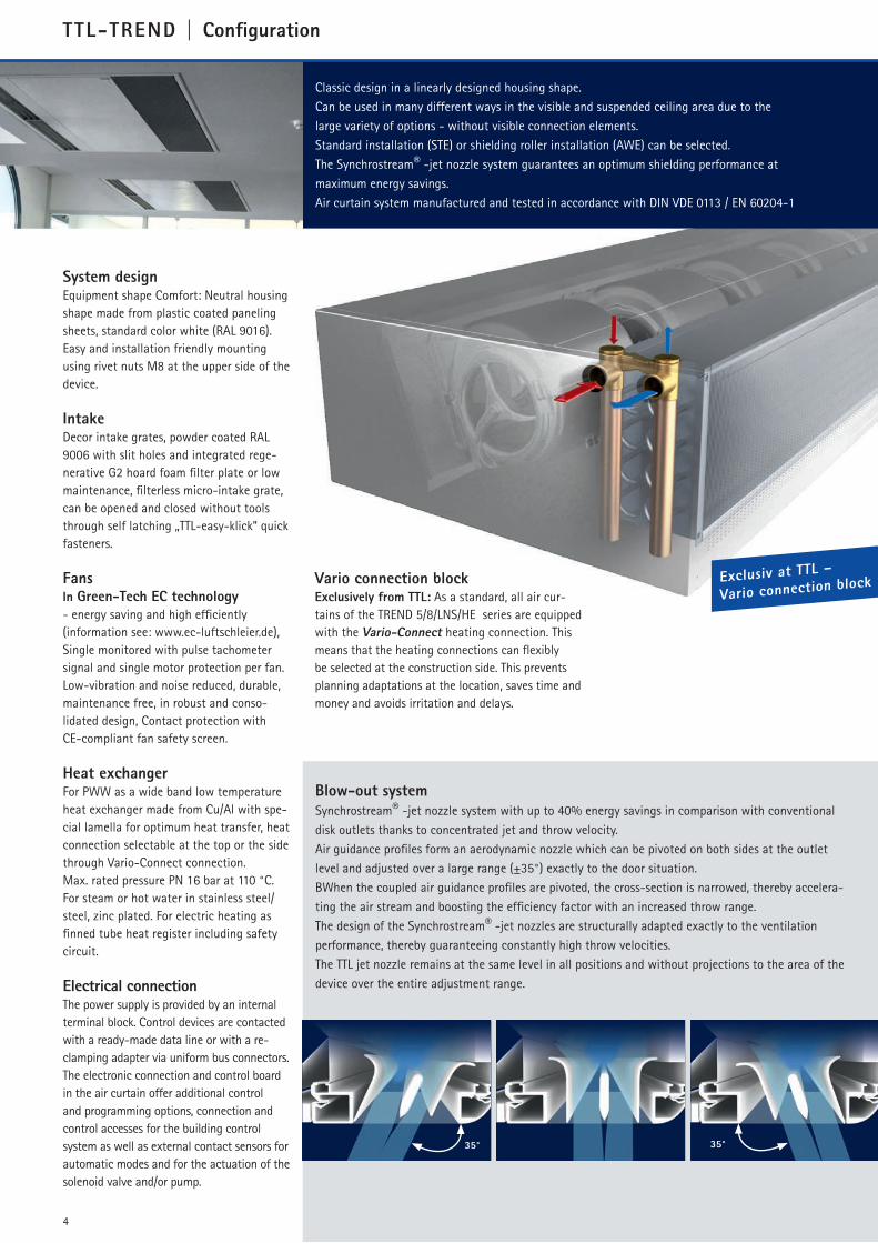
Blow-out system
Synchrostream® -jet nozzle system with up to 40% energy savings in comparison with conventional
disk outlets thanks to concentrated jet and throw velocity.
Air guidance profi les form an aerodynamic nozzle which can be pivoted on both sides at the outlet
level and adjusted over a large range (±35°) exactly to the door situation.
BWhen the coupled air guidance profi les are pivoted, the cross-section is narrowed, thereby accelera-
ting the air stream and boosting the effi ciency factor with an increased throw range.
The design of the Synchrostream® -jet nozzles are structurally adapted exactly to the ventilation
performance, thereby guaranteeing constantly high throw velocities.
The TTL jet nozzle remains at the same level in all positions and without projections to the area of the
device over the entire adjustment range.
Classic design in a linearly designed housing shape.
Can be used in many different ways in the visible and suspended ceiling area due to the
large variety of options - without visible connection elements.
Standard installation (STE) or shielding roller installation (AWE) can be selected.
The Synchrostream® -jet nozzle system guarantees an optimum shielding performance at
maximum energy savings.
Air curtain system manufactured and tested in accordance with DIN VDE 0113 / EN 60204-1
Vario connection blockExclusively from TTL: As a standard, all air cur-
tains of the TREND 5/8/LNS/HE series are equipped
with the Vario-Connect heating connection. This
means that the heating connections can fl exibly
be selected at the construction side. This prevents
planning adaptations at the location, saves time and
money and avoids irritation and delays.
4
Exclusiv at TTL –
Vario connection block

Equipment selection
The physical air exchange in the door area
must be considered for the correct dimen-
sioning of an air curtain system. Major
infl uence factors are the size of the door,
the room surface and room height, the
thermal lift, the back pressure as well a the
number of additional doors and openings in
the building.
The following is normally applicable:
The larger the room surface the higher are
the physical infl uence factors in the door
area.
Factors for the equipment selection
include:
Door size
Room surface
Room height
Thermal lift and back pressure
Number/position of additional doors
and openings
Table 1 includes the room surface to
be shielded for a normal building, with
pressure balance on the door level, for the
pre-selection of an air curtain system.
This information is based on an air curtain
system with the high-effi ciency
TTL Synchrostream® -jet nozzle system.
If other outlets/systems are used, then the
output of the air curtain system must be
increased by up to 40% to shield the same
room surface.
Air curtain systems are designed for the installation in
dry rooms with normally utilized air.
Ambient temperature min. 0 °C / max. 45 °C.
Humidity max. 75 %.
Special solutions on request.
TTL-TREND | Planning data
5
Installation options
STE – standard installation
with air intake from the room direction and
blow-out above the door.
Design of an air curtain roller, whose
rotation direction supports the infl owing
cold air.
Therefore a relative large zone with increa-
sed air movement in the door area.
A solution for smaller rooms, buildings
without vacuum and situations where
permanent work places are not located in
the door area.
AWE – shielding roller installation
with air intake above the door and blow-
out in the room.
Design of a shielding roller, whose rotation
direction works against the infl owing cold
air.
This results in a signifi cant increase of the
shielding performance, a reduction of the
required shielding air volume, the noise
level and a reduction of the zone with in-
creased air movement in the entrance area.
Blow-out height ABlow-out height A
Tabelle 1: Room surface in m² at a blow-out height A in cm
Blow-out height A STE-Installation AWE-Installation
[cm] 230 250 300 320 350 400 230 250 300 320 350 400
TREND … -10 1500 1200 800 600 300 - 4000 3500 2000 1000 500 -
TREND … -15 5500 4000 1500 1200 500 300* 8000 6000 3500 2500 1250 500*
TREND … -LNX 1700 1250 800 500 300 - 3200 2100 1000 750 400 -
* = with modifi ed nozzle width
Schematic diagram
TTL-TREND | Accessories
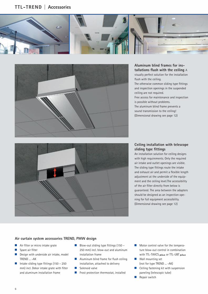
Aluminum blind frames for ins-
tallations flush with the ceiling A
visually perfect solution for the installation
flush with the ceiling.
The otherwise common sliding type fittings
and inspection openings in the suspended
ceiling are not required.
Free access for maintenance and inspection
is possible without problems.
The aluminum blind frame prevents a
sound transmission to the ceiling!
(Dimensional drawing see page 12)
6
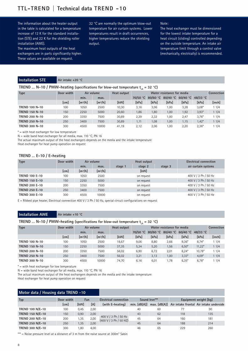
Ceiling installation with telescope
sliding type fittings
An installation solution for ceiling designs
with high requirements. Only the required
air intake and outlet openings are visible.
The sliding type fittings route the intake
and exhaust air and permit a flexible length
adjustment at the underside of the equip-
ment and the ceiling level.The accessibility
of the air filter directly from below is
guaranteed. The area between the adapters
should be designed as an inspection ope-
ning for full equipment accessibility.
(Dimensional drawing see page 12)
Air filter or micro intake grate
Spare air filter
Design with underside air intake, model
TREND ... -AK
Intake sliding type fittings (150 – 250
mm) incl. Dekor intake grate with filter
and aluminum installation frame
Blow-out sliding type fittings (150 –
250 mm) incl. blow-out and aluminum
installation frame
Aluminum blind frame for flush ceiling
installation, attached to delivery
Solenoid valve
Frost protection thermostat, installed
Motor control valve for the tempera-
ture blow-out control in combination
with TTL-TWICS plus or TTL-UBT plus
Wall mounting set
(not for type TREND ... -AK)
Ceiling fastening kit with suspension
paneling (telescopic tube)
Repair switch
Air curtain system accessories TREND, PWW design

7
Actuation through centrall building control system (GLT/DDC)) can be made either selfsus-
taining or in combination with UBT, TWICS, SPACS or TWICS plus/UBT plus operator panels
by an 0..10 V(DC) signal contacted on the connection board installed in the air curtain
device. Thereby the switching points can flexible adjusted or extended for a high switch
and signal transfer safety. The operator panels are connected through customized data lines
with plugs protected against polarity reversal (part of the scope of delivery).
In the delivery condition ex-factory, the
electronic control instruments prevent
the uncontrolled restart after an electri-
cal power failure.
This function can be reprogrammed for
special requirements.
TTL-TREND | Configuration
Control units for devices with pump-warm-water heater (PWW)
Control units for devices with electrical heater (E)
UBT 3E-LCD
Electronic control
– Hand-0-Automatik operator panel for
3-stage controlwith LCD display,
operation through membrane keyboard
with LED key displays
– Actuation of several devices with the
same operating mode up to 30 kW indi-
vidually connected wattage possible
– Different operating modes are possible:
- Automatic contacts for connecting the
door and room thermostat
- Servo tracking
- Post heat mode if door is closed
through control unit and room thermo-
stat
- DDC release, potential-free contacts
for service and fault notifications
- RESET programmings for motor protec-
tion
- Cool-down circuit, adjustable
- Safety signal „Contactor gluing“ for the
actuation of a circuit breaker
Control unit related accessories
– Room thermostats
– Thermostat clocks
– Door or gate contacts
- As limit switches, IP 65, impact resis-
tant encapsulated
- As Reed switch with active and passive
part, can be glued on or screwed on
– Adapter CAN bus/terminal -reconnect
block in housing for terminal transitions
from internal CAN bus to cable supplied
by construction site (e.g. YSTI, ISDN)
TTL air curtain devices can also directly controlled and regulated in performance by an external
0..10 V signal of a building management system.
TTL-UBT
Electronic control
- Hand-0-Automatik operator panel for
5-stepped or continuous (in combination
with EC motors) control with LCD
display, operation through membrane
keyboard with LED key displays
- Display of status and operating datas
statistics and service hints
- Filter monitoring via display
- Actuation of up to 10 devices with the
same operating mode is possible
- Key-lock function and display settings
programmable
- Different operating modes are possible:
- Automatic contacts for connecting the
door contact and room thermostat
- Servo tracking
- Post heat mode if door is closed
through control unit and room
thermostat
- DDC release, potential-free contacts
for service and fault notifications
- RESET programmings for motor and
frost protection
- Timer mode with seven-day schedule
TTL-SPACS
Electronic control
- Manual-0-Automatic operator panel for
stepless controls, with membrane k
board with large LCD display
- Basic functions same as for UBT 5,
however, with essential expanded
operating scope and service menu
- Actuation of several devices separately
possible through addressing, therefore
especially feasible for air curtains with
special or customer required functions
- Programmable control panels
for air curtains with special functions
or customer required solutions
- Additional features:
- Codable key lock
- Clock and timer with week programm
- Temperature display of a connected
room sensor
- Actuation of TTL eQomax air curtains
- Actuation of air curtains with heating
and refrigeration functions
- Actuation of butterfly valves possible
- Different display modes
TTL-TWICS plus and TTL-UBT plus
Electronic controls
– Self-sufficient control of TTL air curtain
systems with an analysis of the climate
related conditions in the door area, tem-
perature measurement through infrared
sensor
– The performance is adjusted through the
operating stage circuits and a control of
the blow-out temperature
– By establishing switching threshold va-
lues, the control unit is freely program-
mable for the floor temperature and the
respective operating stage.
- Setback operation with activ appropria-
ted reduction of blow out temperature
The switching values can be coupled with a
timer mode.
When using the electronic control units
TTL-TWICS plus or TTL-UBT plus, then
an especially energy saving operation of
air curtain systems is possible, because a
continuous balance of the set and current
operating values takes place under consi-
deration of the required equipment output.
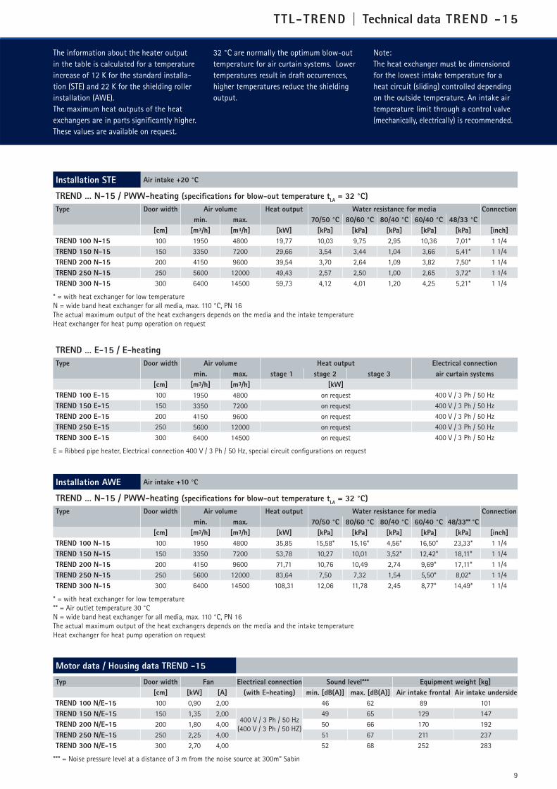
TTL-TREND | Technical data TREND -10
Installation STE Air intake +20 °C
TREND … N-10 / PWW-heating (specifications for blow-out temperature tLA
= 32 °C)
Type Door width Air volume Heat output Water resistance for media Connection
min. max. 70/50 °C 80/60 °C 80/40 °C 60/40 °C 48/33 °C
[cm] [m³/h] [m³/h] [kW] [kPa] [kPa] [kPa] [kPa] [kPa] [inch]
TREND 100 N-10 100 1050 2500 10,30 3,16 3,06 1,00 3,28 3,08* 1 1/4
TREND 150 N-10 150 2250 5000 20,60 1,86 1,80 1,00 1,92 3,93* 1 1/4
TREND 200 N-10 200 3350 7500 30,89 2,39 2,32 1,00 2,47 3,76* 1 1/4
TREND 250 N-10 250 3400 7500 30,89 1,11 1,08 1,00 1,15 1,42* 1 1/4
TREND 300 N-10 300 4500 10000 41,19 2,12 2,06 1,00 2,20 2,36* 1 1/4
* = with heat exchanger for low temperature
N = wide band heat exchanger for all media, max. 110 °C, PN 16
The actual maximum output of the heat exchangers depends on the media and the intake temperature
Heat exchanger for heat pump operation on request
Installation AWE Air intake +10 °C
TREND … N-10 / PWW-heating (specifications for blow-out temperature tLA
= 32 °C)
Type Door width Air volume Heat output Water resistance for media Connection
min. max. 70/50 °C 80/60 °C 80/40 °C 60/40 °C 48/33 °C
[cm] [m³/h] [m³/h] [kW] [kPa] [kPa] [kPa] [kPa] [kPa] [inch]
TREND 100 N-10 100 1050 2500 18,67 9,06 8,80 2,66 9,36* 8,74* 1 1/4
TREND 150 N-10 150 2250 5000 37,35 5,34 5,20 1,56 6,50* 11,22* 1 1/4
TREND 200 N-10 200 3350 7500 56,02 6,90 6,72 2,01 6,24* 10,78* 1 1/4
TREND 250 N-10 250 3400 7500 56,02 3,21 3,13 1,00 3,33* 4,09* 1 1/4
TREND 300 N-10 300 4500 10000 74,70 6,16 6,01 1,78 6,35* 6,78* 1 1/4
* = with heat exchanger for low temperature
N = wide band heat exchanger for all media, max. 110 °C, PN 16
The actual maximum output of the heat exchangers depends on the media and the intake temperature
Heat exchanger for heat pump operation on request
Motor data / Housing data TREND -10
Typ Door width Fan Electrical connection Sound leve*** Equipment weight [kg]
[cm] [kW] [A] (with E-heating) min. [dB(A)] max. [dB(A)] Air intake frontal Air intake underside
TREND 100 N/E-10 100 0,45 2,00 40 60 77 90
TREND 150 N/E-10 150 0,90 2,00400 V / 3 Ph / 50 Hz
(400 V / 3 Ph / 50 HZ)
43 62 118 135
TREND 200 N/E-10 200 1,35 2,00 45 64 160 181
TREND 250 N/E-10 250 1,35 2,00 45 64 188 214
TREND 300 N/E-10 300 1,80 4,00 46 65 229 260
*** = Noise pressure level at a distance of 3 m from the noise source at 300m“ Sabin
8
The information about the heater output
in the table is calculated for a temperature
increase of 12 K for the standard installa-
tion (STE) and 22 K for the shielding roller
installation (AWE).
The maximum heat outputs of the heat
exchangers are in parts significantly higher.
These values are available on request.
32 °C are normally the optimum blow-out
temperature for air curtain systems. Lower
temperatures result in draft occurrences,
higher temperatures reduce the shielding
output.
Note:
The heat exchanger must be dimensioned
for the lowest intake temperature for a
heat circuit (sliding) controlled depending
on the outside temperature. An intake air
temperature limit through a control valve
(mechanically, electrically) is recommended.
TREND … E-10 / E-heating
Type Door width Air volume Heat output Electrical connection
min. max. stage 1 stage 2 stage 3 air curtain systems
[cm] [m³/h] [m³/h] [kW]
TREND 100 E-10 100 1050 2500 on request 400 V / 3 Ph / 50 Hz
TREND 150 E-10 150 2250 5000 on request 400 V / 3 Ph / 50 Hz
TREND 200 E-10 200 3350 7500 on request 400 V / 3 Ph / 50 Hz
TREND 250 E-10 250 3400 7500 on request 400 V / 3 Ph / 50 Hz
TREND 300 E-10 300 4500 10000 on request 400 V / 3 Ph / 50 Hz
E = Ribbed pipe heater, Electrical connection 400 V / 3 Ph / 50 Hz, special circuit configurations on request
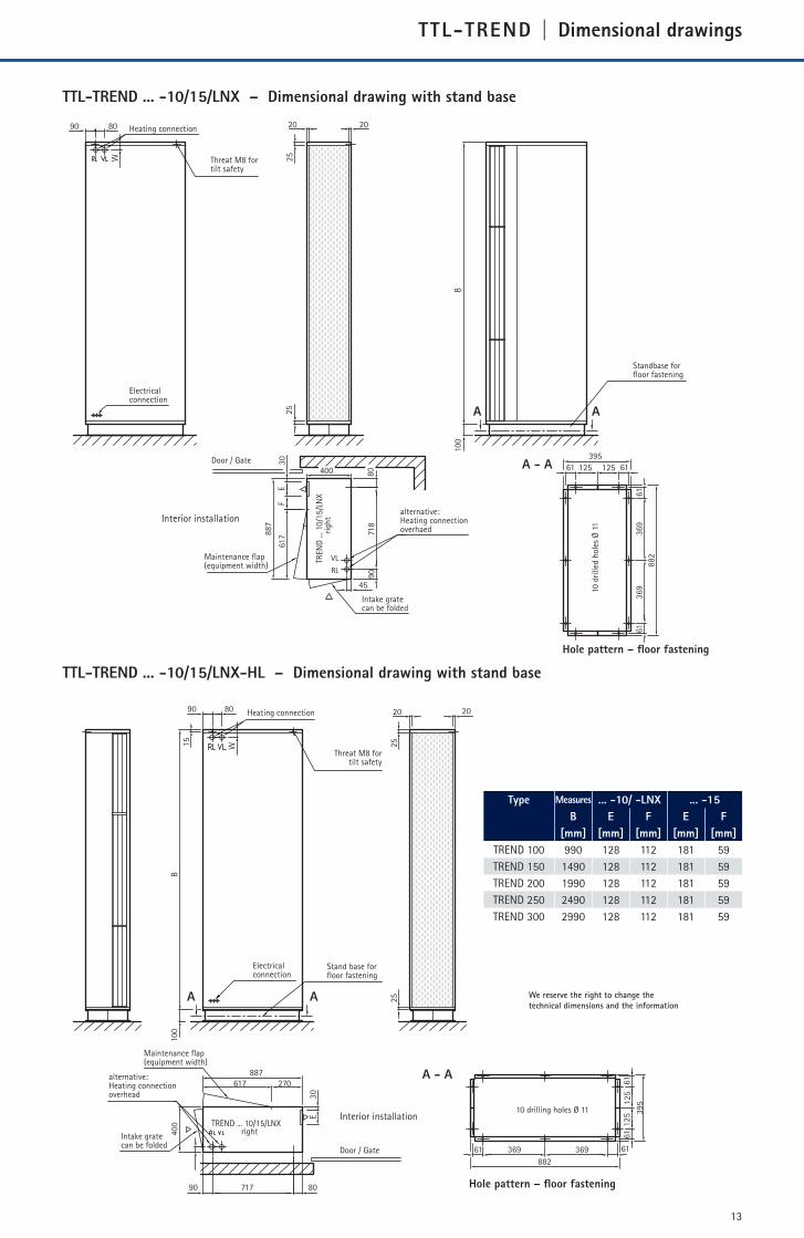
TTL-TREND | Technical data TREND -15
Installation STE Air intake +20 °C
TREND … N-15 / PWW-heating (specifications for blow-out temperature tLA
= 32 °C)
Type Door width Air volume Heat output Water resistance for media Connection
min. max. 70/50 °C 80/60 °C 80/40 °C 60/40 °C 48/33 °C
[cm] [m³/h] [m³/h] [kW] [kPa] [kPa] [kPa] [kPa] [kPa] [inch]
TREND 100 N-15 100 1950 4800 19,77 10,03 9,75 2,95 10,36 7,01* 1 1/4
TREND 150 N-15 150 3350 7200 29,66 3,54 3,44 1,04 3,66 5,41* 1 1/4
TREND 200 N-15 200 4150 9600 39,54 3,70 2,64 1,09 3,82 7,50* 1 1/4
TREND 250 N-15 250 5600 12000 49,43 2,57 2,50 1,00 2,65 3,72* 1 1/4
TREND 300 N-15 300 6400 14500 59,73 4,12 4,01 1,20 4,25 5,21* 1 1/4
* = with heat exchanger for low temperature
N = wide band heat exchanger for all media, max. 110 °C, PN 16
The actual maximum output of the heat exchangers depends on the media and the intake temperature
Heat exchanger for heat pump operation on request
Installation AWE Air intake +10 °C
TREND … N-15 / PWW-heating (specifications for blow-out temperature tLA
= 32 °C)
Type Door width Air volume Heat output Water resistance for media Connection
min. max. 70/50 °C 80/60 °C 80/40 °C 60/40 °C 48/33** °C
[cm] [m³/h] [m³/h] [kW] [kPa] [kPa] [kPa] [kPa] [kPa] [inch]
TREND 100 N-15 100 1950 4800 35,85 15,58* 15,16* 4,56* 16,50* 23,33* 1 1/4
TREND 150 N-15 150 3350 7200 53,78 10,27 10,01 3,52* 12,42* 18,11* 1 1/4
TREND 200 N-15 200 4150 9600 71,71 10,76 10,49 2,74 9,69* 17,11* 1 1/4
TREND 250 N-15 250 5600 12000 83,64 7,50 7,32 1,54 5,50* 8,02* 1 1/4
TREND 300 N-15 300 6400 14500 108,31 12,06 11,78 2,45 8,77* 14,49* 1 1/4
* = with heat exchanger for low temperature
** = Air outlet temperature 30 °C
N = wide band heat exchanger for all media, max. 110 °C, PN 16
The actual maximum output of the heat exchangers depends on the media and the intake temperature
Heat exchanger for heat pump operation on request
Motor data / Housing data TREND -15
Typ Door width Fan Electrical connection Sound level*** Equipment weight [kg]
[cm] [kW] [A] (with E-heating) min. [dB(A)] max. [dB(A)] Air intake frontal Air intake underside
TREND 100 N/E-15 100 0,90 2,00 46 62 89 101
TREND 150 N/E-15 150 1,35 2,00400 V / 3 Ph / 50 Hz
(400 V / 3 Ph / 50 HZ)
49 65 129 147
TREND 200 N/E-15 200 1,80 4,00 50 66 170 192
TREND 250 N/E-15 250 2,25 4,00 51 67 211 237
TREND 300 N/E-15 300 2,70 4,00 52 68 252 283
*** = Noise pressure level at a distance of 3 m from the noise source at 300m“ Sabin
9
The information about the heater output
in the table is calculated for a temperature
increase of 12 K for the standard installa-
tion (STE) and 22 K for the shielding roller
installation (AWE).
The maximum heat outputs of the heat
exchangers are in parts significantly higher.
These values are available on request.
32 °C are normally the optimum blow-out
temperature for air curtain systems. Lower
temperatures result in draft occurrences,
higher temperatures reduce the shielding
output.
Note:
The heat exchanger must be dimensioned
for the lowest intake temperature for a
heat circuit (sliding) controlled depending
on the outside temperature. An intake air
temperature limit through a control valve
(mechanically, electrically) is recommended.
TREND … E-15 / E-heating
Type Door width Air volume Heat output Electrical connection
min. max. stage 1 stage 2 stage 3 air curtain systems
[cm] [m³/h] [m³/h] [kW]
TREND 100 E-15 100 1950 4800 on request 400 V / 3 Ph / 50 Hz
TREND 150 E-15 150 3350 7200 on request 400 V / 3 Ph / 50 Hz
TREND 200 E-15 200 4150 9600 on request 400 V / 3 Ph / 50 Hz
TREND 250 E-15 250 5600 12000 on request 400 V / 3 Ph / 50 Hz
TREND 300 E-15 300 6400 14500 on request 400 V / 3 Ph / 50 Hz
E = Ribbed pipe heater, Electrical connection 400 V / 3 Ph / 50 Hz, special circuit configurations on request

10
Installation STE Air intake +20 °C
TREND … N-LNX / PWW-heating (specifications for blow-out temperature tLA
= 32 °C)
Type Door width Air volume Heat output Water resistance for media Connection
min. max. 70/50 °C 80/60 °C 80/40 °C 60/40 °C 48/33 °C
[cm] [m³/h] [m³/h] [kW] [kPa] [kPa] [kPa] [kPa] [kPa] [inch]
TREND 100 N-LNX 100 1450 3200 13,18 4,89 4,74 1,45 5,06 3,24* 1 1/4
TREND 150 N-LNX 150 2200 4800 19,77 1,73 1,67 1,00 1,82 3,66* 1 1/4
TREND 200 N-LNX 200 3000 6400 26,36 1,80 1,75 1,00 1,87 2,84* 1 1/4
TREND 250 N-LNX 250 3750 8000 32,95 1,24 1,21 1,00 1,29 1,59* 1 1/4
TREND 300 N-LNX 300 4450 9600 39,54 1,98 1,92 1,00 2,04 2,50* 1 1/4
* = with heat exchanger for low temperature
N = wide band heat exchanger for all media, max. 110 °C, PN 16
The actual maximum output of the heat exchangers depends on the media and the intake temperature
Heat exchanger for heat pump operation on request
Installation AWE Air intake +10 °C
TREND … N-LNX / PWW-heating (specifications for blow-out temperature tLA
= 32 °C)
Type Door width Air volume Heat output Water resistance for media Connection
min. max. 70/50 °C 80/60 °C 80/40 °C 60/40 °C 48/33 °C
[cm] [m³/h] [m³/h] [kW] [kPa] [kPa] [kPa] [kPa] [kPa] [inch]
TREND 100 N-LNX 100 1450 3200 23,90 14,07 13,69 4,11 7,84* 12,07* 1 1/4
TREND 150 N-LNX 150 2200 4800 35,85 4,97 4,83 1,45 6,05* 10,44* 1 1/4
TREND 200 N-LNX 200 3000 6400 47,81 5,19 5,05 1,52 4,71* 8,13* 1 1/4
TREND 250 N-LNX 250 3750 8000 59,76 3,61 3,51 1,05 2,65* 4,59* 1 1/4
TREND 300 N-LNX 300 4450 9600 71,71 5,72 5,58 1,66 4,18* 7,23* 1 1/4
* = with heat exchanger for low temperature
N = wide band heat exchanger for all media, max. 110 °C, PN 16
The actual maximum output of the heat exchangers depends on the media and the intake temperature
Heat exchanger for heat pump operation on request
Motor data / Housing data TREND -LNX
Typ Door width Fan Electrical connection Sound level*** Equipment weight [kg]
[cm] [kW] [A] (with E-heating) min. [dB(A)] max. [dB(A)] Air intake frontal Air intake underside
TREND 100 N/E-LNX 100 0,40 1,4 41 52 89 101
TREND 150 N/E-LNX 150 0,60 1,4400 V / 3 Ph / 50 Hz
(400 V / 3 Ph / 50 HZ)
41 53 129 147
TREND 200 N/E-LNX 200 0,80 2,8 42 54 170 192
TREND 250 N/E-LNX 250 1,00 2,8 42 54 211 237
TREND 300 N/E-LNX 300 1,20 2,8 44 55 252 283
*** = Noise pressure level at a distance of 3 m from the noise source at 300m“ Sabin
TREND … E-LNX / E-heating
Type Door width Air volume Heat output Electrical connection
min. max. stage 1 stage 2 stage 3 air curtain systems
[cm] [m³/h] [m³/h] [kW]
TREND 100 E-LNX 100 1450 3200 on request 400 V / 3 Ph / 50 Hz
TREND 150 E-LNX 150 2200 4800 on request 400 V / 3 Ph / 50 Hz
TREND 200 E-LNX 200 3000 6400 on request 400 V / 3 Ph / 50 Hz
TREND 250 E-LNX 250 3750 8000 on request 400 V / 3 Ph / 50 Hz
TREND 300 E-LNX 300 4450 9600 on request 400 V / 3 Ph / 50 Hz
E = Ribbed pipe heater, Electrical connection 400 V / 3 Ph / 50 Hz, special circuit configurations on request
TTL-TREND | Technical data TREND -LNX
The information about the heater output
in the table is calculated for a temperature
increase of 12 K for the standard installa-
tion (STE) and 22 K for the shielding roller
installation (AWE).
The maximum heat outputs of the heat
exchangers are in parts significantly higher.
These values are available on request.
32 °C are normally the optimum blow-out
temperature for air curtain systems. Lower
temperatures result in draft occurrences,
higher temperatures reduce the shielding
output.
Note:
The heat exchanger must be dimensioned
for the lowest intake temperature for a
heat circuit (sliding) controlled depending
on the outside temperature. An intake air
temperature limit through a control valve
(mechanically, electrically) is recommended.

TTL-TREND | Dimensional drawing for visible installation
TTL-TREND ... -10/15/LNX - Air intake frontal (STD)
TTL-TREND ... -10/15/LNX-AK – Air intake underside
Type Measures ... N/NT -10/ -LNX ... N/NT -15 Number of
B C D E F E F fastening points
[mm] [mm] [mm] [mm] [mm] [mm] [mm] STD AK
TREND 100 990 960 – 128 112 181 59 4 6
TREND 150 1490 1460 – 128 112 181 59 4 6
TREND 200 1990 1960 – 128 112 181 59 4 6
TREND 250 2490 2460 1245 128 112 181 59 6 9
TREND 300 2990 2960 1495 128 112 181 59 6 9
11
alternative:Heating connectionsideways
Intake gratecan be folded
Thread M8 for ceiling installation
Thread M8 for ceiling installation
Intake gratecan be folded
Heating connection
Heating connection
Maintenance flap (equipment width)
Maintenance flap (equipment width)
Electrical connection
Electrical connection
alternative:Heating connectionsideways
VL
RL
15 15
80
90
20
20
400
E 617
887
30
B
25F
64
C
45
80 717 90
25
D D
VL
RL
15 15
80
470
400
E 617
1267
30
B
25F
64
C
45
80 717 390
25
D D
80
363 17
We reserve the right to change thetechnical dimensions and the information
We reserve the right to change thetechnical dimensions and the information

303030
a
3030
b
30
B DE
CE
C
Loch
ble
ch R
e 10 x
13
oder
Mik
roansa
uggit
ter
30
4 5353,5
30 30
422,5
30
B
IF
HF
H
Länge=K
Länge=L Länge=N
Länge=BLänge=B
Länge=MGerät
Zwischendecke
Decke demontierbar
für Ventilatorwartung
1335
17338
395,5
387
422,5
1267
30
150
150
155 -
280
e
d
c
b f
TTL-TREND | Dimensional drawings for ceiling installation (aluminum blind frame + sliding type fittings)
Type MeasuresOutside dimensions
of frame
Ceiling
cutout dimensions... -10/ -LNX ... -15 Number of
fastening
pointsB C D Width x depth Width x depth E F E F
[mm] [mm] [mm] [mm] [mm] [mm] [mm] [mm] [mm]
TREND 100 990 960 – 1076 x 1353 1046 x 1323 128 112 181 59 6
TREND 150 1490 1460 – 1576 x 1353 1546 x 1323 128 112 181 59 6
TREND 200 1990 1960 – 2076 x 1353 2046 x 1323 128 112 181 59 6
TREND 250 2490 2460 1245 2576 x 1353 2546 x 1323 128 112 181 59 9
TREND 300 2990 2960 1495 3076 x 1353 3046 x 1323 128 112 181 59 9
TTL-TREND ... -10/15/LNX-AK – Dimensional drawing with aluminum blind frame
TTL-TREND ... -10/15/LNX-AK – Dimensional drawing with sliding type fittings
TypeB*
[mm]
C
[mm]
D
[mm]
E
[mm]
F
[mm]
TREND 100 999 939 – – 936
TREND 150 1499 712 – 15 1436
TREND 200 1999 962 – 15 1936
TREND 250 2499 712 985 15 1216
TREND 300 2999 962 985 15 1466
Typea
[mm]
b*
[mm]
c
[mm]
d
[mm]
e
[mm]
f
[mm]
TREND ...-10 128 248 219 211 94 665
TREND ...-15 181 301 272 264 121 612
TREND …-LNX 128 248 219 211 94 665
TypeH
[mm]
I
[mm]
K
[mm]
L
[mm]
M
[mm]
N
[mm]
TREND 100 1,5 – 963 969 969 963
TREND 150 1,5 – 1463 1469 1469 1463
TREND 200 1,5 – 1963 1969 1969 1963
TREND 250 1,5 4 2463 2469 2469 2463
TREND 300 1,5 4 2963 2969 2969 2963
* = Outside dimension intake blind/blow-out blind
Intake gratecan be folded
Maintenace flap(equipment width)
Electrical connectionHeating connection
Threat M8 for ceiling installation
Frame width
alternative:Heating connectionsideways
Blind frame Air curtain device
12
VLRL
Detail Z
Z
15 15
80
470
400
E 617
1267
30
B
25
F
64
C
45
80 717 390
25
D D 80
363 17
30
43
1353
VL
RL Ceiling
Perfo
rate
d m
etal
plat
e Re
10x
13or
mic
ro g
rate
Grate, view from below
Device
Ceiling removable for fan maintenace
Length = K
Length = L Length = N
Length = B Length = B
Length = M
Suspended ceiling
Blow-out nozzle,view from below
We reserve the right to change thetechnical dimensions and the information
We reserve the right to change thetechnical dimensions and the information
13
TTL-TREND | Dimensional drawings
Heating connection
Threat M8 fortilt safety
Standbase forfl oor fastening
10 d
rilled
hole
s Ø
11
Hole pattern – fl oor fastening
alternative:Heating connection overhaed
Electrical connection
Door / Gate
Interior installation
Maintenance fl ap(equipment width)
Intake gratecan be folded
Heating connection
Threat M8 for tilt safety
Stand base forfl oor fastening
10 drilling holes Ø 11
Hole pattern – fl oor fastening
alternative:Heating connectionoverhead
Electrical connection
Door / Gate
Interior installation
Maintenance fl ap(equipment width)
Intake gratecan be folded
TTL-TREND ... -10/15/LNX – Dimensional drawing with stand base
TTL-TREND ... -10/15/LNX-HL – Dimensional drawing with stand base
Type Measures ... -10/ -LNX ... -15
B E F E F
[mm] [mm] [mm] [mm] [mm]
TREND 100 990 128 112 181 59
TREND 150 1490 128 112 181 59
TREND 200 1990 128 112 181 59
TREND 250 2490 128 112 181 59
TREND 300 2990 128 112 181 59
TREN
D ...
10/
15/L
NX
righ
t
61
61
369
887
25
395
882
H
20
25
2090
80
A A
125 125 61
718
90
617
FE
30
45
A - A100
80
400
369
B
61
W
VL
RL
369
15
61
TREND ... 10/15/LNX right
61
369
887
25
395
882
400
20
25
2090
B100
A A
125
125
61
617 270
E30
61
A - A
80
71790 80
W
We reserve the right to change thetechnical dimensions and the information
TTL Torluftschleier GmbH
Fabrikstr. 3 · D-73650 Winterbach
Fon +49 (0) 71 81 / 40 09 - 0
Fax +49 (0) 71 81 / 40 09 - 10
[email protected] · www.luftschleier.de
System solut ions for al l appl icat ion areas
© T
TL T
orl
uft
schle
ier
Gm
bH
· 2
016/1
0-0
1 · W
e re
serv
e th
e ri
ght
to c
hange
tech
nic
al in
form
ati
on d
ue
to f
urt
her
dev
elopm
ent.
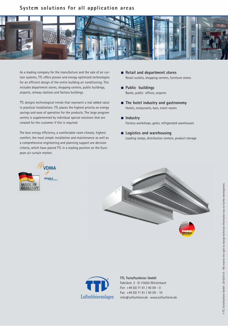
As a leading company for the manufacture and the sale of air cur-
tain systems, TTL offers proven and energy optimized technologies
for an effi cient design of the entire building air conditioning. This
includes department stores, shopping centers, public buildings,
airports, railway stations and factory buildings.
TTL designs technological trends that represent a real added value
in practical installations. TTL places the highest priority on energy
savings and ease of operation for the products. The large program
variety is supplemented by individual special solutions that are
created for the customer if this is required.
The best energy effi ciency, a comfortable room climate, highest
comfort, the most simple installation and maintenance as well as
a comprehensive engineering and planning support are decision
criteria, which have placed TTL in a leading position on the Euro-
pean air curtain market.
Retail and department stores
Retail outlets, shopping centers, furniture stores
Public buildings
Banks, public offi ces, airports
The hotel industry and gastronomy
Hotels, restaurants, bars, event rooms
Industry
Factory workshops, gates, refrigerated warehouses
Logistics and warehousing
Loading ramps, distribution centers, product storage