traulsen service manual - my.hobartcorp.com service manual can help the service technician maintain,...
TRANSCRIPT
MASTER SERVICE MANUAL
For All Full Size Undercounter, G-Series and R&A
Refrigerator, Freezer, Dual-Temp and Hot Food
Units
Traulsen 4401 Blue Mound Road Fort Worth, Texas
76106 Phone: (800) - 825 - 8220
Part Number 375-60351-00 Form Number TR36015 revised 3/17
1
Introduction
Traulsen provides this manual as an aid to the service technician in installation, operation and maintenance of Traulsen units from year 2010 to present. When used properly. This service manual can help the service technician maintain, troubleshoot and diagnose most of the problems and malfunctions that may occur with the controllers. While we believe that most aspects of the controllers are covered in this manual should you encounter a condition not addressed, or require a wiring diagram please contact.
ITW Refrigeration Traulsen
4401 Blue Mound Road Fort Worth, TX 76106 Attn: Service Department
Phone: (800) 825-8220 Fax: (817) 740-6757
To improve your service communication experience be sure to have the following available when contacting technical support:
Serial number Model number A detailed explanation of the problem.
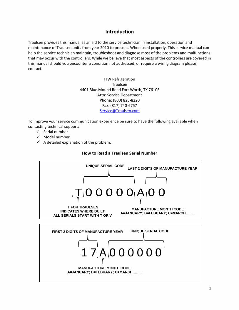
How to Read a Traulsen Serial Number
T FOR TRAULSEN INDICATES WHERE BUILT
ALL SERIALS START WITH T OR V
MANUFACTURE MONTH CODE A=JANUARY; B=FEBUARY; C=MARCH……..
LAST 2 DIGITS OF MANUFACTURE YEAR UNIQUE SERIAL CODE
MANUFACTURE MONTH CODE A=JANUARY; B=FEBUARY; C=MARCH……..
FIRST 2 DIGITS OF MANUFACTURE YEAR UNIQUE SERIAL CODE
1 7 A 0 0 0 0 0 0
2
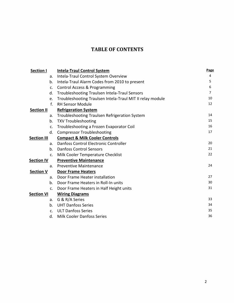
TABLE OF CONTENTS
Section I Intela-Traul Control System Page
a. Intela-Traul Control System Overview 4
b. Intela-Traul Alarm Codes from 2010 to present 5
c. Control Access & Programming 6
d. Troubleshooting Traulsen Intela-Traul Sensors 7
e. Troubleshooting Traulsen Intela-Traul MIT II relay module 10
f. RH Sensor Module 12
Section II Refrigeration System
a. Troubleshooting Traulsen Refrigeration System 14
b. TXV Troubleshooting 15
c. Troubleshooting a Frozen Evaporator Coil 16
d. Compressor Troubleshooting 17
Section III Compact & Milk Cooler Controls
a. Danfoss Control Electronic Controller 20
b. Danfoss Control Sensors 21
c. Milk Cooler Temperature Checklist 22
Section IV Preventive Maintenance
a. Preventive Maintenance 24
Section V Door Frame Heaters
a. Door Frame Heater installation 27
b. Door Frame Heaters in Roll-In units 30
c. Door Frame Heaters in Half Height units 31
Section VI Wiring Diagrams
a. G & R/A Series 33
b. UHT Danfoss Series 34
c. ULT Danfoss Series 35
d. Milk Cooler Danfoss Series 36

3
Section I
Intela-Traul Control System

4
I. a – Intela-Traul Control System Overview Intela-Traul Components:
Component Description
Control Head
Microprocessor Control
User Interface
Relay Module
DC Power Supply
Blower Relay
Defrost Heater Relay
Door Frame Heater Relay
Supplies 12VDC to Compressor Relay
Hybrid Relay
Hybrid Solid State Relay
Compressor/Condenser Relay
12VDC Coil Voltage
Sensors
Green – Cabinet Air Blue – Evaporator Coil Yellow – Liquid Line
Table 1
Basic Control Function:
Function Component Trigger
Cycles Door Frame Heaters Door Frame Heaters Based on Control Settings (will vary)
Cycles Evaporator Blower Motor Evaporator Blower Based on Control Settings (will vary)
Controls Defrost Cycle Defrost Heater Time Initiated, Terminated by Blue Evap Coil Sensor Temp
Cycles Refrigeration System Refrigeration System Green Cabinet Air Sensor Temp
Triggers Alarm/Trouble Code Alarms Based on Control Settings
Table 2

5
I. b - Intela-Traul Alarm Codes from 2010 to present
Alarm Description Clear Alarm
Refrigeration System Low Charge Repair Refrigeration System
Low Cabinet Temperature Alarm
Return Cabinet Temperature to Normal Range
High Cabinet Temperature Alarm
Return Cabinet Temperature to Normal Range
Door Open Alarm Close Door
Power Loss Alarm
Press Alarm Cancel
Clean Condenser Alarm Clear/Clean Condenser Coil
Coil Sensor Open or Shorted Replace Coil Sensor
Cab Sensor Open or Shorted Replace Cabinet Sensor
Discharge Line Sensor open or shorted
Replace Discharge Line Sensor
Defrost Terminates by Time, Not Temperature, for 72 hours.
Troubleshoot Defrost Cycle
Cab Sensor Open or Shorted Replace Cabinet Sensor
Coil Sensor Open or Shorted Replace Coil Sensor
Liquid Line Sensor Open or Shorted Replace Liquid Line Sensor
Low Cabinet Temperature Alarm Return Cabinet Temperature to Normal Range
High Cabinet Temperature Alarm
Return Cabinet Temperature to Normal Range
Table 3

6
I. c – Intela-Traul Control Access & Parameters To access the engineering/service menu follow the instruction below. As seen in Figures 1 & 2.
Figure 1
INTELA-TRAUL Access
Press Display Press
If control does not have
INTELA-TRAUL Key Parameters Parameter Description
Set Point
Set Point Differential
Set Point High (Equip Prior to 2010 only)
Set Point Low (Equip Prior to 2010 only)
Evaporator Coil Sensor Temp
Cabinet Air Sensor Temp
Liquid Line Sensor Temp
Start Manual Defrost
Intervals Between Defrost (In hours)
Defrost Termination Temperature
Drip Time After Defrost
Length of Defrost (In Minutes)
Reset to Factory Defaults
SET
SET
SET
SET
SET
Figure 2

7
I. d - Troubleshooting Traulsen Intela-Traul Sensors
Sensor Function:
Cabinet Sensor (Green): The Cabinet sensor reads the temperature of the return air and relays that value back to the control head. The control head either cycles the compressor on or off depending on the temperature set points. If cabinet sensor reads 60⁰F (15 ⁰C) or higher the unit will not go into defrost and you can’t put into manual defrost.
Coil Sensor (Blue): The Coil sensor reads the evaporator coil core temperature and returns that value back to the control head. The control head uses this input to terminate the defrost cycle at 45⁰F (7.2⁰C) evaporator core temperature. In addition the control
head uses the evaporator coil core temperature to control evaporator fan delay.
Liquid Line Sensor (Yellow): The Liquid Line sensor reads the temperature of the liquid line and returns that value back to the control head. The control head uses the liquid line temperature to trigger a clean coil alarm at 140⁰F (60⁰C) (R&A series only) &
cycles the compressor off on high temp limit at 160⁰F (71.1⁰C) liquid line temperature.
Basic Troubleshooting: All sensors (cabinet, coil, liquid line) can be tested for accuracy using a Volt Ohm Meter.
When checking a sensor value through the control a reading of -40⁰F (-40⁰C) indicates
an open in the sensor or sensor circuit and a reading of 266⁰F (130⁰C) indicates a short
in the sensor or sensor circuit. See Table 4 for control head sensor parameters.
An ice & water solution consisting of mostly ice with just enough water to submerse the sensor should be used to create a controlled environment of approximately 32⁰F (0⁰C).
This solution likely needs to be agitated or stirred to maintain a consistent temperature throughout. At 32⁰F (0⁰C) all sensors should return an Ohm reading of 32,000 Ohms +/-
10%. See Table 5 below for temperature & Ohms relationship of all Intela-Traul sensors.
TEMP (OF) R (OHMS) TEMP (
OC)
20 46.2K -6.7
25 39.9K -3.9
30 34.6K -1.1
32 32.7K 0.0
35 30.1K 1.7
40 26.1K 4.4
Table 5
Sensor Parameter
Cabinet Air Evaporator Coil
Liquid Line Table 4
8
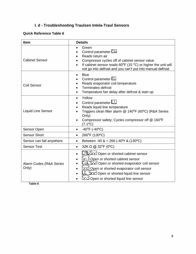
I. d - Troubleshooting Traulsen Intela-Traul Sensors
Quick Reference Table 6
Item Details
Cabinet Sensor
Green
Control parameter
Reads return air
Compressor cycles off of cabinet sensor value
If cabinet sensor reads 60⁰F (15 ⁰C) or higher the unit will not go into defrost and you can’t put into manual defrost.
Coil Sensor
Blue
Control parameter
Reads evaporator coil temperature
Terminates defrost
Temperature fan delay after defrost & start up
Liquid Line Sensor
Yellow
Control parameter
Reads liquid line temperature
Triggers clean filter alarm @ 140⁰F (60⁰C) (R&A Series
Only)
Compressor safety; Cycles compressor off @ 160⁰F (7.1⁰C)
Sensor Open -40⁰F (-40⁰C)
Sensor Short 266⁰F (130⁰C)
Sensor can fail anywhere Between -40 & + 266 (-40⁰F & (130⁰C)
Sensor Test 32K Ω @ 32⁰F (0⁰C)
Alarm Codes (R&A Series Only)
Open or shorted cabinet sensor
Open or shorted cabinet sensor
Open or shorted evaporator coil sensor
Open or shorted evaporator coil sensor
Open or shorted liquid line sensor
Open or shorted liquid line sensor
Table 6

9
I. d - Troubleshooting Traulsen Intela-Traul Sensors
Advanced Trouble Shooting Tips
There are a variety of reasons for the symptoms listed in Table 7. This troubleshooting table is intended to address the most common reasons associated with the Intela-Traul sensors only. Further troubleshooting outside the scope of this document may be required.
Symptom Possible Causes
Cabinet temperature display reads lower temperature than actual cabinet temperature
Evaporator coil is frozen up
Defective cabinet sensor
Cabinet sensor not in proper location
Cabinet temperature display reads higher temperature than actual cabinet temperature
Defective cabinet sensor
Air flow obstruction
Cabinet sensor not in proper location
Evaporator coil is frozen up Evaporator coil sensor is out of tolerance and terminating defrost to soon
Cabinet air sensor is out of tolerance causing cabinet air temp to run too low
Display temperature reads -40⁰F (-40⁰C)
Cabinet sensor is open
Cabinet sensor is disconnected
Cabinet sensor wire harness is open
Cabinet sensor pin connector is loose or has a weak connection
Compressor cycles off before cabinet temperature is satisfied
Liquid line sensor is out of tolerance and return to high of a temperature causing the compressor to cycle off
Liquid line is reaching 160⁰F (71.1⁰C) and
cycling the compressor off on high temp limit Table 7
10
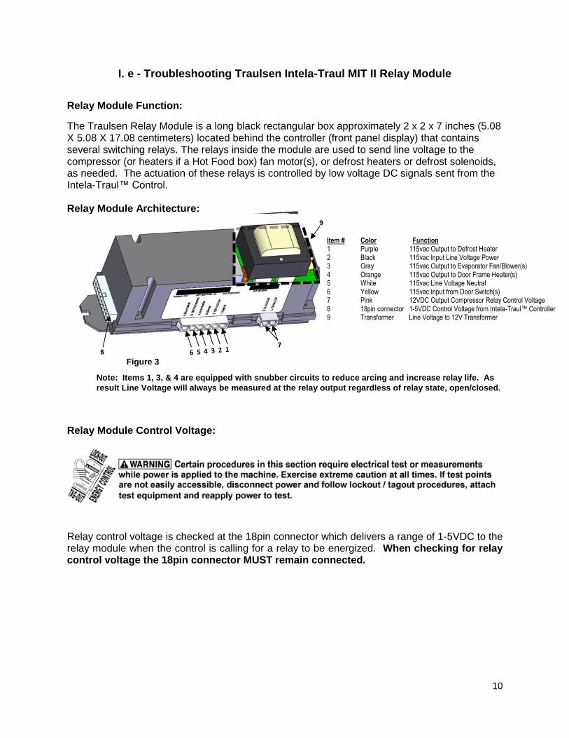
I. e - Troubleshooting Traulsen Intela-Traul MIT II Relay Module
Relay Module Function:
The Traulsen Relay Module is a long black rectangular box approximately 2 x 2 x 7 inches (5.08 X 5.08 X 17.08 centimeters) located behind the controller (front panel display) that contains several switching relays. The relays inside the module are used to send line voltage to the compressor (or heaters if a Hot Food box) fan motor(s), or defrost heaters or defrost solenoids, as needed. The actuation of these relays is controlled by low voltage DC signals sent from the Intela-Traul™ Control. Relay Module Architecture:
Relay Module Control Voltage:
Relay control voltage is checked at the 18pin connector which delivers a range of 1-5VDC to the relay module when the control is calling for a relay to be energized. When checking for relay control voltage the 18pin connector MUST remain connected.
Note: Items 1, 3, & 4 are equipped with snubber circuits to reduce arcing and increase relay life. As
result Line Voltage will always be measured at the relay output regardless of relay state, open/closed.
Item # Color Function 1 Purple 115vac Output to Defrost Heater 2 Black 115vac Input Line Voltage Power 3 Gray 115vac Output to Evaporator Fan/Blower(s) 4 Orange 115vac Output to Door Frame Heater(s) 5 White 115vac Line Voltage Neutral 6 Yellow 115vac Input from Door Switch(s) 7 Pink 12VDC Output Compressor Relay Control Voltage 8 18pin connector 1-5VDC Control Voltage from Intela-Traul™ Controller 9 Transformer Line Voltage to 12V Transformer
Figure 3

11
I. e - Troubleshooting Traulsen Intela-Traul MIT II Relay Module
Relay Module Control Voltage (Cont):
Relay Module Output Voltage:
If the 1-5VDC control voltage from the Intela-Traul™ has been confirmed but the corresponding component is not energized output voltage from the relay module needs to be confirmed. The simplest way to confirm whether or not the relay inside the relay module has failed is to jump out the relay contacts. You can do this by unplugging the six pin connector and jump pin 2 (Black, 115vac input) to the corresponding output pin. If the component energizes then the relay module likely needs to be replaced. If the component still does not energize then further troubleshooting of the component is needed.
Pin No. Color Signal 1 Gray Blower 2 Orange Door Heater 3 Green Alarm From Controller 4 Black Return to Horn 5 Unused 6 Unused 7 White/Purple -RS485 8 Black Ground 9 White 12vac 10 Blue Compressor 11 Purple Defrost 12 Yellow Door Open Signal 13 Red Power to Horn 14 Unused 15 Unused 16 Pink +RS485 17 Red 12 VDC Controller Power 18 Black 12vac
Check control voltage by inserting meter leads into the
back of the 18pin connector at the appropriate points.
18pin connector must be connected to the relay
module.
Figure 4

12
I. f - RH Sensor Module
The Intela-Traul RH module (Relative Humidity Sensor) is found on the Traulsen Energy Star
rated units, from October 2014 to the present. This technical bulletin may not cover all the
situations that may arise in the field and final diagnosis of field based equipment is the sole
responsibility of the technician contracted to perform any work required.
Functionality:
The RH module senses the ambient temperature and relative humidity and communicates the information to the MIT II control. The MIT II control uses this data to perform the following tasks. As seen in Table 8.
Cycle the door heater based on ambient temperature and humidity conditions.
Increase/decrease the intervals between defrosts based on the number of door
open/close events and the ambient temperature conditions. + or -75%.
Parameters Table:
Displayed Parameter Name Sample Value Description
Relative Humidity (Ambient)
55.0 Relative humidity of the room.
Dry Bulb Temperature
75.0 Ambient temperature of the room.
Dew Point Temperature
65.0 Calculated dew point temperature.
Table 8
Troubleshooting Table:
Symptom Possible cause Solution
Excessive condensation on the door.
Inaccurate reading from the RH module.
Unplug RH sensor. Replace the RH sensor module.
Coil freezes up. The RH module extends the interval between defrost based on ambient conditions.
Unplug RH sensor. Put unit into manual defrost. Replace RH sensor.
Table 9 Note: You can disconnect the RH Sensor and the unit will run with its default settings.
13
Section II
Refrigeration System
14
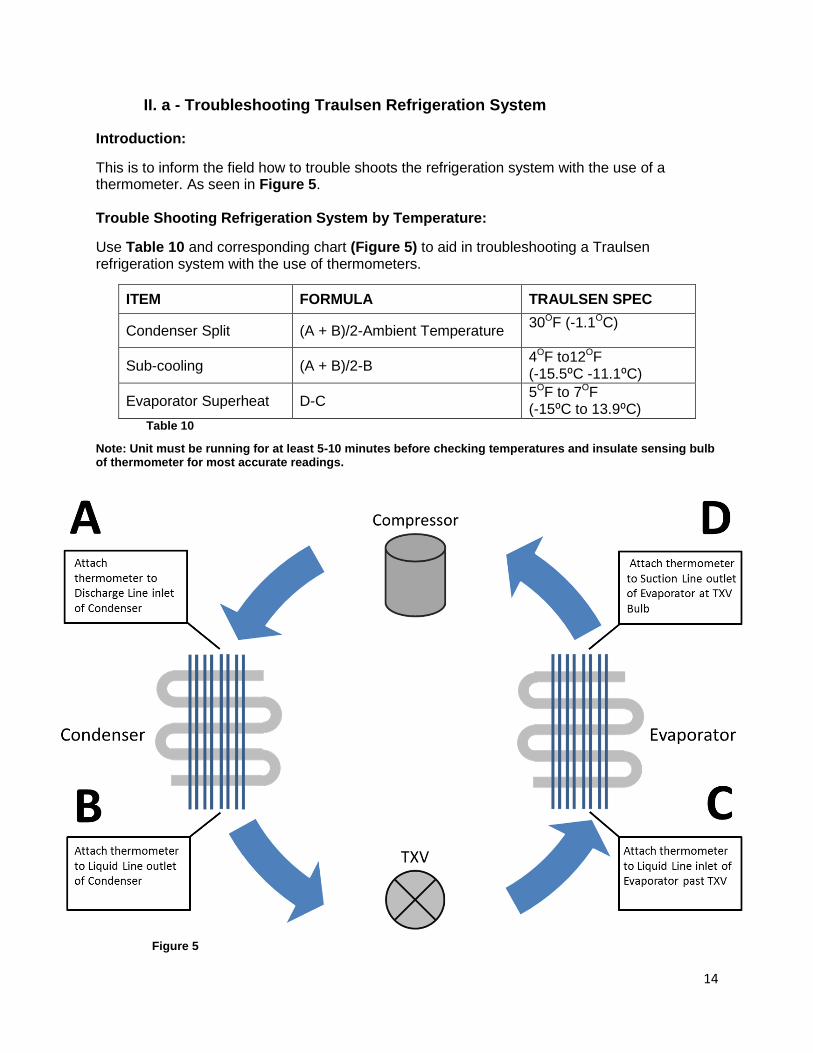
II. a - Troubleshooting Traulsen Refrigeration System
Introduction:
This is to inform the field how to trouble shoots the refrigeration system with the use of a thermometer. As seen in Figure 5. Trouble Shooting Refrigeration System by Temperature:
Use Table 10 and corresponding chart (Figure 5) to aid in troubleshooting a Traulsen refrigeration system with the use of thermometers.
ITEM FORMULA TRAULSEN SPEC
Condenser Split (A + B)/2-Ambient Temperature 30OF (-1.1OC)
Sub-cooling (A + B)/2-B 4OF to12OF (-15.5⁰C -11.1⁰C)
Evaporator Superheat D-C 5OF to 7OF (-15⁰C to 13.9⁰C)
Table 10
Note: Unit must be running for at least 5-10 minutes before checking temperatures and insulate sensing bulb of thermometer for most accurate readings.
Figure 5

15
II. b - TXV Troubleshooting
Standard Operating Parameters:
Superheat – 7⁰F (-13.9⁰C)
Subcooling – 4OF-12OF (-15.5⁰C TO -11.1⁰C)
Troubleshooting:
Table 11
Moisture Contamination: A restriction caused by moisture will thaw when the TXV is warmed and the system will begin to
function properly until the moisture finds its way back to the TXV and freezes at the orifice
again. See Table 11.
Superheat Subcooling Diagnosis
Above 7F Below 4F Refrigerant Charge is Low
Below 5F Above 12F System Overcharged
Above 7F Above 12F Restriction in High Side or Metering Device
(As measured in Figure 5, Page 14)

16
II. c - Troubleshooting a Frozen Evaporator Coil
Table 12 is intended to aid in diagnosing the root cause of a frozen evaporator coil on a Traulsen upright reach-in refrigerator or freezer. This may not cover all situations that may arise in the field and final diagnosis of field based equipment is the sole responsibility of the technician contracted to perform any work required.
Frozen Evaporator Troubleshooting Table
Potential Causes Details
Cabinet Sensor out of tolerance (See TTB006 Sensors for sensor troubleshooting)
Color: Green
Control parameter
Reads return air
Compressor cycles off of cabinet sensor value
Coil Sensor out of tolerance (See TTB006 Sensors for sensor troubleshooting)
Color: Blue
Control parameter
Reads evaporator coil temperature
Terminates defrost @ 45⁰F (7.2⁰C)
Fan delay
Ambient Air Infiltration
Door(s) not closing properly
Gasket(s) not sealing properly
Door(s) left open for extended periods of time
Evaporator hump cover not sealed properly
Compressor relay stuck closed
Coil voltage 12VDC
Coil wires: Pink
Contacts o Common: Black wire o N/O: Blue wire
Lack of Air Flow Evaporator fan motor not functioning
Obstruction in air duct or at evaporator coil
Refrigeration System (Traulsen recommends the refrigeration system be tested using the methods outlined in TTB009)
Low charge
Restricted metering device
Moisture/contaminates in the system
Defrost Heater Defrost heater open
Defrost heater circuit or relay open
Control Settings
Set point to low (refrigerator only)
o Control parameters: or & (depending on the age of control system)
Defrost lockouts set to frequently
o Control parameters: , , , Table 12

17
II. d - Compressor Troubleshooting
Tools Required:
Basic hand tools
Clamp around amp meter
Volt Ohm meter
Basic 3 in 1(1/2 HP) Terminology:
OEM – Original Equipment Manufacturer – Refers to the manufacturer of a piece of equipment or component.
RLA – Rated Load Amps – The OEM test conditions amperage rating (does not necessarily indicate the normal running amperage as conditions and applications can vary from OEM test conditions)
LRA – Locked Rotor Amps – The OEM test condition lock rotor amperage rating indicating the expected amperage at which a motor does not turn when power is applied.
Start Components – The capacitor and relay combinations used to start and/or run a compressor motor consist of a start capacitor and start relay if IAA is shown on the serial number of the compressor. If CAA is listed then there will be a potential relay along with a start capacitor and a run capacitor.
Ω= OHM= Unit Resistance R= Run S= Start C= Common
Figure 6 shows the readings of the resistance through the compressor motor windings. (C-S C-R). If the windings are good the start winding resistance (C-S) will always be higher than the run winding resistance (C-R).
Note: This example shows one set of possible combinations that can be seen in the field. Resistance values will vary between different compressors.
Figure 6

18
II. d - Compressor Troubleshooting
Basic Troubleshooting:
What is my amp draw and voltage when the compressor is starting?
What is the resistance of the windings?
What is the RLA (Rated Load Amps) of the compressor?
What is the LRA (Locked Rotor Amps) of the compressor?
Check the start components? Symptom Reason Possible Resolution
0 amps Check for voltage between C & R terminals.
No: Check external overload & find where power loss is. Yes: open winding or the internal overload is open
Amps lower then RLA
Lower head & high suction. Weak valves, busted crankshaft or connecting rod.
Slightly higher amps then RLA
Overload opens after compressor runs for a time.
Bad run capacitor, tight bearings, or winding issues.
Very high amps but not LRA
Issue with compressor windings.
Ohm windings and compare with manufacturer’s resistances.
Reading LRA Compressor not starting, reading 5 to 6 times RLA.
Check start capacitor, start relay &wires for burning, try 3 in 1. Check voltage drop (+/-10%) and for resistance.
Table 13
19
Section III
Compact & Milk Cooler Controls
20
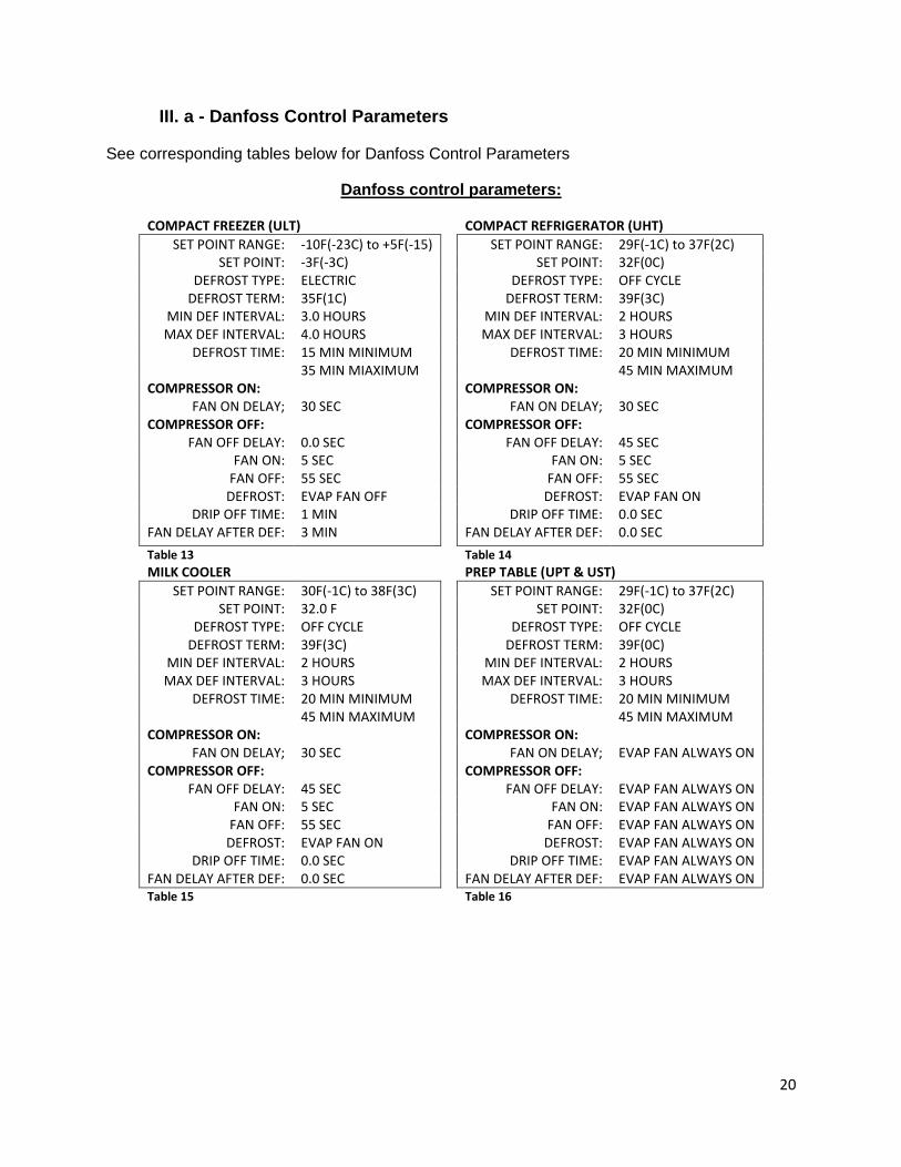
III. a - Danfoss Control Parameters
See corresponding tables below for Danfoss Control Parameters
Danfoss control parameters:
COMPACT FREEZER (ULT) COMPACT REFRIGERATOR (UHT)
SET POINT RANGE: -10F(-23C) to +5F(-15) SET POINT RANGE: 29F(-1C) to 37F(2C) SET POINT: -3F(-3C) SET POINT: 32F(0C)
DEFROST TYPE: ELECTRIC DEFROST TYPE: OFF CYCLE DEFROST TERM: 35F(1C) DEFROST TERM: 39F(3C)
MIN DEF INTERVAL: 3.0 HOURS MIN DEF INTERVAL: 2 HOURS MAX DEF INTERVAL: 4.0 HOURS MAX DEF INTERVAL: 3 HOURS
DEFROST TIME: 15 MIN MINIMUM DEFROST TIME: 20 MIN MINIMUM 35 MIN MIAXIMUM 45 MIN MAXIMUM COMPRESSOR ON: COMPRESSOR ON:
FAN ON DELAY; 30 SEC FAN ON DELAY; 30 SEC COMPRESSOR OFF: COMPRESSOR OFF:
FAN OFF DELAY: 0.0 SEC FAN OFF DELAY: 45 SEC FAN ON: 5 SEC FAN ON: 5 SEC
FAN OFF: 55 SEC FAN OFF: 55 SEC DEFROST: EVAP FAN OFF DEFROST: EVAP FAN ON
DRIP OFF TIME: 1 MIN DRIP OFF TIME: 0.0 SEC FAN DELAY AFTER DEF: 3 MIN FAN DELAY AFTER DEF: 0.0 SEC
Table 13 Table 14
MILK COOLER PREP TABLE (UPT & UST)
SET POINT RANGE: 30F(-1C) to 38F(3C) SET POINT RANGE: 29F(-1C) to 37F(2C) SET POINT: 32.0 F SET POINT: 32F(0C)
DEFROST TYPE: OFF CYCLE DEFROST TYPE: OFF CYCLE DEFROST TERM: 39F(3C) DEFROST TERM: 39F(0C)
MIN DEF INTERVAL: 2 HOURS MIN DEF INTERVAL: 2 HOURS MAX DEF INTERVAL: 3 HOURS MAX DEF INTERVAL: 3 HOURS
DEFROST TIME: 20 MIN MINIMUM DEFROST TIME: 20 MIN MINIMUM 45 MIN MAXIMUM 45 MIN MAXIMUM COMPRESSOR ON: COMPRESSOR ON:
FAN ON DELAY; 30 SEC FAN ON DELAY; EVAP FAN ALWAYS ON COMPRESSOR OFF: COMPRESSOR OFF:
FAN OFF DELAY: 45 SEC FAN OFF DELAY: EVAP FAN ALWAYS ON FAN ON: 5 SEC FAN ON: EVAP FAN ALWAYS ON
FAN OFF: 55 SEC FAN OFF: EVAP FAN ALWAYS ON DEFROST: EVAP FAN ON DEFROST: EVAP FAN ALWAYS ON
DRIP OFF TIME: 0.0 SEC DRIP OFF TIME: EVAP FAN ALWAYS ON FAN DELAY AFTER DEF: 0.0 SEC FAN DELAY AFTER DEF: EVAP FAN ALWAYS ON Table 15 Table 16

21
III. b - Danfoss Control Troubleshooting
DANFOSS SENSOR OHM VALUES
Sensor Temperature Ohm value
Cabinet sensor (S1) 32⁰F (0⁰C)
16.00 Ω
Coil Sensor (S2) 32⁰F (0⁰C)
16.00 Ω
Spindle (S3) N/A 4-26 Ω (slight tolerance) Table 17
Note: If the red light starts flashing this indicates a sensor failure.
To start manual defrost:
1. Turn unit off and make sure the spindle is all the way in the left position.
2. Turn unit on and wait for the blower to come on.
3. Turn spindle all the way to the right position for 3 seconds.
4. Turn spindle all the way to the left position for 3 seconds.
5. Turn to the middle position and wait for unit to go into manual defrost.
Troubleshooting Table:
Potential Causes Possible Solutions
Faulty Danfoss control
See page 18 for Danfoss parameters.
Faulty defrost termination Check to make sure the defrost termination is not stuck open.
Faulty coil sensor
If the coil sensor is faulty the unit will not go into its manual defrost. If either cabinet or coil sensors faulty the indicator light on top of the controller will be blinking red.
Place the sensor in a glass of 32⁰F (0⁰C) ice water. Ohm sensor and you
should get 16 K ohms. Table 18
22
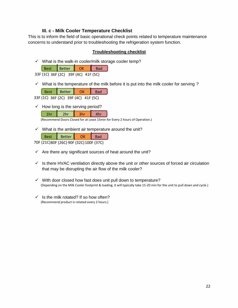
III. c - Milk Cooler Temperature Checklist
This is to inform the field of basic operational check points related to temperature maintenance
concerns to understand prior to troubleshooting the refrigeration system function.
Troubleshooting checklist
What is the walk-in cooler/milk storage cooler temp?
What is the temperature of the milk before it is put into the milk cooler for serving ?
How long is the serving period?
a
What is the ambient air temperature around the unit?
Are there any significant sources of heat around the unit?
Is there HVAC ventilation directly above the unit or other sources of forced air circulation
that may be disrupting the air flow of the milk cooler?
With door closed how fast does unit pull down to temperature?
Is the milk rotated? If so how often?
33F (1C) 36F (2C) 39F (4C) 41F (5C)
Best Better OK Bad
33F (1C) 36F (2C) 39F (4C) 41F (5C)
Best Better OK Bad
(Recommend Doors Closed for at Least 15min for Every 2 hours of Operation.)
(Depending on the Milk Cooler footprint & loading, it will typically take 15-20 min for the unit to pull down and cycle.) off)
1hr 2hr 3hr 4hr
70F (21C) 80F (26C) 100F (37C) 90F (32C)
Best Better OK Bad
(Recommend product is rotated every 2 hours.)
23
Section IV
Preventive Maintenance

24
IV. a - Preventative Maintenance
Introduction:
This is to inform field of recommended preventative maintenance procedures. Depending on application PM schedule may vary.
INSPECT AND CLEAN
Why Sanitation and prolong cabinet life
Frequency Daily
Time required 5 minutes to prepare 10 minutes to complete
Preparation Have a Soft Cloth. Baking soda and water mixed to a 1 TBSP (15mL) baking soda to 1 pint (473.2mL) water ratio.
Cleaning
Apply with a dampened cloth and wipe in the direction of the metal grain. (Avoid the use of strong detergents and gritty, abrasive cleaners as they may tend to mar and scratch the surface. Do NOT use cleansers containing chlorine; this may promote corrosion of the stainless steel.)
Inspection Visually inspect the unit for signs of wear that may require repair. Table 19
INSPECT DOOR GASKET
Why Long reliable service life
Frequency Every 3 Months
Time required
10 minutes to complete
Inspection
Open cabinet door (s) to inspect gasket. Pull gasket with hand and visually inspect gasket (s) for tear, dirt, mold or worn gasket. Replace as needed. The model and serial number is required when placing a parts order call the Traulsen Parts Department at 800-825-8220.
Table 20
25
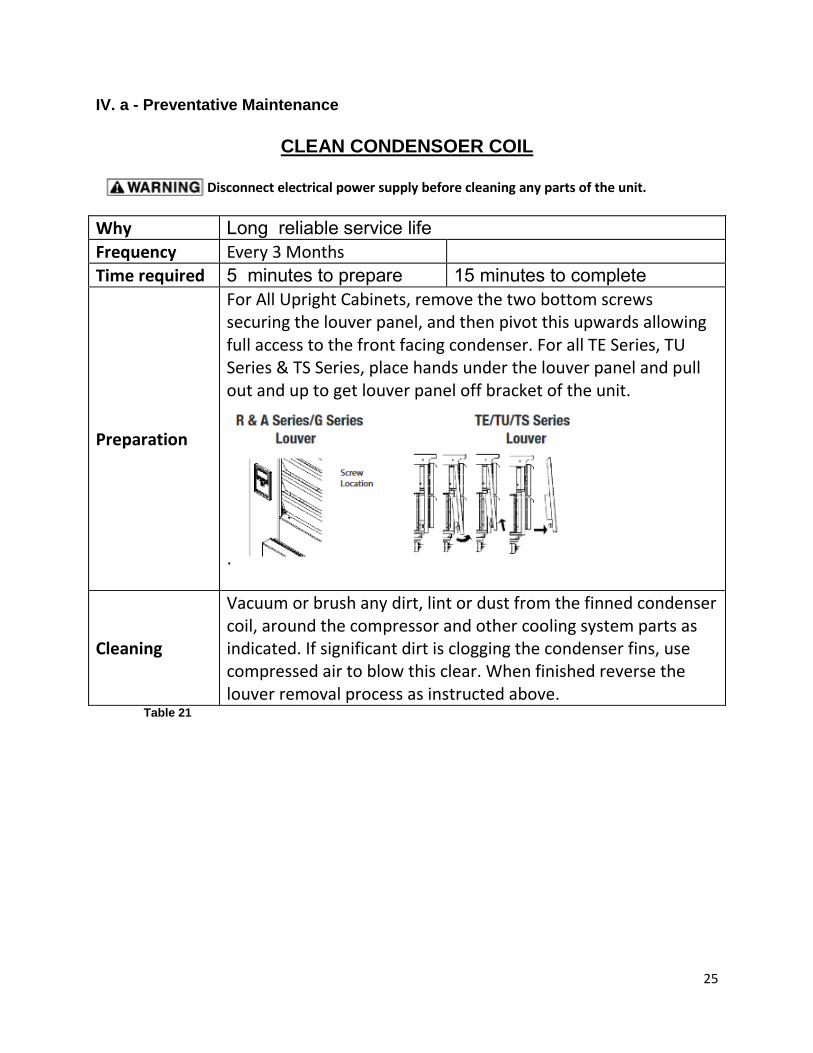
IV. a - Preventative Maintenance
CLEAN CONDENSOER COIL
Why Long reliable service life
Frequency Every 3 Months
Time required 5 minutes to prepare 15 minutes to complete
Preparation
For All Upright Cabinets, remove the two bottom screws securing the louver panel, and then pivot this upwards allowing full access to the front facing condenser. For all TE Series, TU Series & TS Series, place hands under the louver panel and pull out and up to get louver panel off bracket of the unit.
.
Cleaning
Vacuum or brush any dirt, lint or dust from the finned condenser coil, around the compressor and other cooling system parts as indicated. If significant dirt is clogging the condenser fins, use compressed air to blow this clear. When finished reverse the louver removal process as instructed above.
Table 21
Disconnect electrical power supply before cleaning any parts of the unit.

26
Section VI
Door Frame Heater installation
27
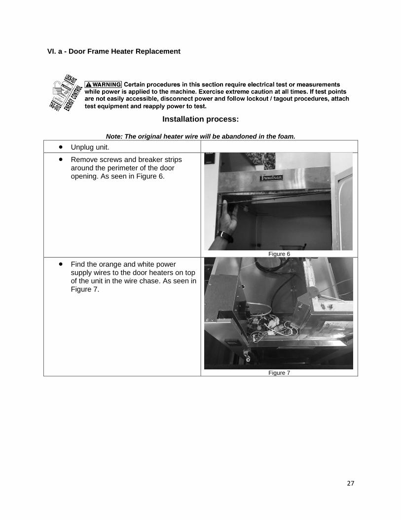
VI. a - Door Frame Heater Replacement
Installation process:
Note: The original heater wire will be abandoned in the foam.
Unplug unit. Remove screws and breaker strips
around the perimeter of the door opening. As seen in Figure 6.
Figure 6
Find the orange and white power supply wires to the door heaters on top of the unit in the wire chase. As seen in Figure 7.
Figure 7
28
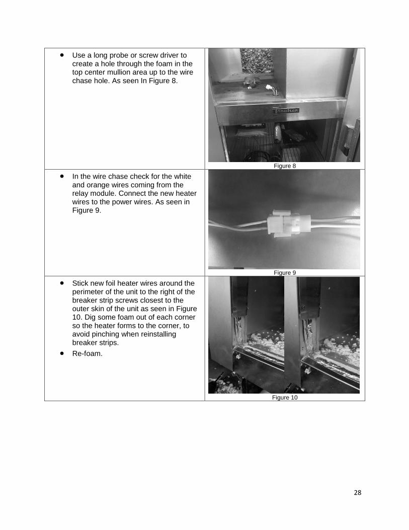
Use a long probe or screw driver to create a hole through the foam in the top center mullion area up to the wire chase hole. As seen In Figure 8.
Figure 8
In the wire chase check for the white and orange wires coming from the relay module. Connect the new heater wires to the power wires. As seen in Figure 9.
Figure 9
Stick new foil heater wires around the perimeter of the unit to the right of the breaker strip screws closest to the outer skin of the unit as seen in Figure 10. Dig some foam out of each corner so the heater forms to the corner, to avoid pinching when reinstalling breaker strips.
Re-foam.
Figure 10
29
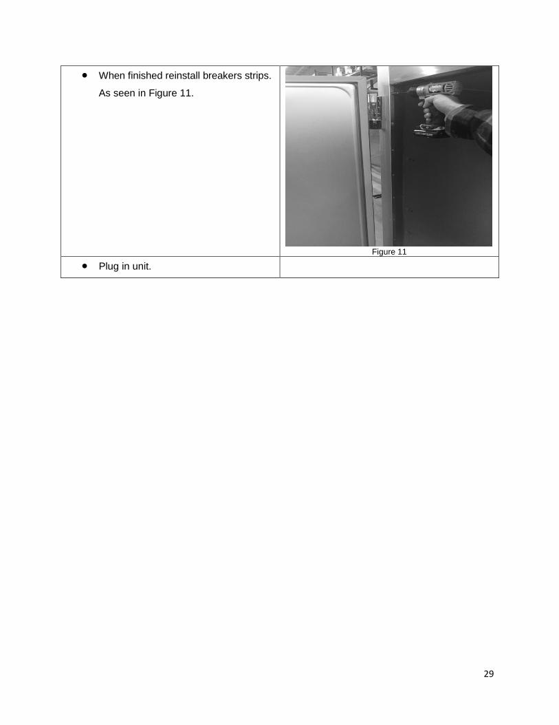
When finished reinstall breakers strips.
As seen in Figure 11.
Figure 11
Plug in unit.
30
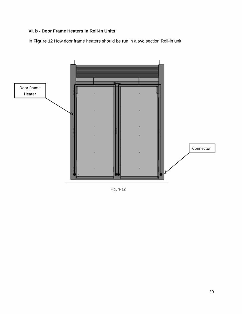
VI. b - Door Frame Heaters in Roll-In Units In Figure 12 How door frame heaters should be run in a two section Roll-in unit.
Figure 12
Connector
Door Frame
Heater

31
VI. c - Door Frame Heaters in Half Height Units In Figure 13 How door frame heaters should be run in a Half Height unit.
Figure 13
Door Frame
Heater
Use a long probe
to create a hole
through the foam
in the top center
mullion.
32
Section VII
General Wiring Diagrams

33
VII. a – G/R/A Series Reach-In
34
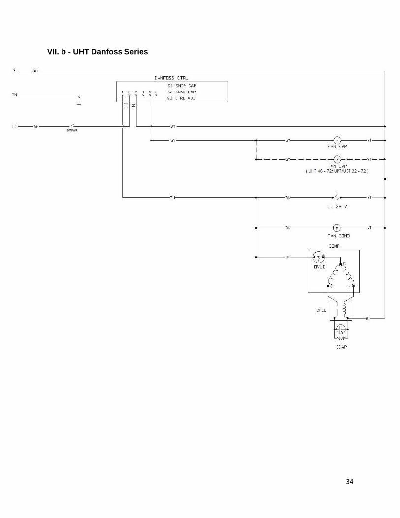
VII. b - UHT Danfoss Series

35
Vll. c - ULT Danfoss Series

36
VII. d - Milk Cooler Danfoss Series