transverse stage iii installation/owner’s … stage iii/1.8t tvs3 instruction... · transverse...
TRANSCRIPT

T R A N S V E R S E S T A G E I I I I N S T A L L A T I O N / O W N E R ’ S M A N U A LAUDI PERFORMANCE & RACING1 0 2 7 - B O p e l i k a R o a d A u b u r n A l a b a m a 3 6 8 3 0 S T A G E 3

AUDI PERFORMANCE & RACING1 0 2 7 - B O p e l i k a R o a d A u b u r n A l a b a m a 3 6 8 3 0
AUDI PERFORMANCE & RACING1 0 2 7 - B O p e l i k a R o a d A u b u r n A l a b a m a 3 6 8 3 0
TABLE OF CONTENTS
i.
ii.
iii.
iv.
v.
vi.
vii.
viii
Disclaimer
Tools Needed
Parts in the Kit
Before You Start
ECU Removal
Installation Procedure
First Drive
Troubleshooting Contact Information
AUDI PERFORMANCE & RACING1 0 2 7 - B O p e l i k a R o a d A u b u r n A l a b a m a 3 6 8 3 0
AUDI PERFORMANCE & RACING1 0 2 7 - B O p e l i k a R o a d A u b u r n A l a b a m a 3 6 8 3 0
1. 17mm lug socket2. 19mm socket3. 17mm socket4. 16mm socket5. 13mm socket6. 12mm deep well socket7. 12mm swivel socket8. 12mm stubby9. 10mm socket10. 12 point 30mm socket11. 5/8” spark plug socket12. #10 3box socket (12 point torx)13. 22mm wrench14. 19mm wrench for oil15. 18mm wrench 16. 17mm wrench17. 13mm wrench18. 10mm wrench
AUDI PERFORMANCE & RACING, LLC does not endorse modifi cation of vehicles for use in public highways where warranty or government regulations may be violated. As an express condition of sale of any performance part, the buyer acknowledges and agrees to use the performance parts for the modifi cation of vehicles in a manner consistent with any and all local and federal regulations and laws, including sanctioned OFF-ROAD competitive events. Emission related aftermarket parts that modify the emission control system may not be legal for sale or use on pollution controlled vehicles. Parts sold by AUDI PERFORMANCE & RACING, LLC are legal only for racing vehicles which may never be used upon a public highway. Performance parts and equipment are sold AS IS without any warranty whatsoever, unless indicated otherwise. There is no warranty implied or stated due to the intended use and purpose of performance parts. While every effort is made to provide technical information and assistance, we have no control over owner installation, modifi cation, and unusual stress that performance parts are subject to. The buyer assumes all responsibility for determining the suitability of the product. The entire risk as to quality and performance parts is assumed by the buyer. In the event such parts proves defective following their purchase and installation, the buyer, not AUDI PERFORMANCE & RACING, LLC, the manufacturer, the distributor, or retailer, assumes the entire cost of any necessary servicing, repair, or replacement. AUDI PERFORMANCE & RACING, LLC will not be responsible for any direct or indirect, actual or incidental expenses attributable to the use of any performance parts, or to delay and inconvenience caused by the necessity of repairing or replacing performance parts.
CONDITIONS OF SALE
Buyers of parts from AUDI PERFORMANCE & RACING or any authorized distributor are warned that they are sold for off-highway use only and special warranty provisions apply. Performance parts may exceed the design limits of the vehicle and its subsystems. Suitability and implementation of parts is at the sole discretion of the purchaser. Customer agrees to operate the vehicle under the conditions set forth in this agreement and agrees to hold AUDI PERFORMANCE & RACING, LLC, its employees, corporate offi cers, and vendors, harmless by reason of any claim, damages, accident, or injuries resulting from the installation of the parts or the use of the vehicle with the installed parts.OFF-HIGHWAY OR RACING USE
Because Country, state or provincial laws and regulations may prohibit removal or modifi cation of components that were installed on vehicles by their manufacturer to meet motor vehicle safety regulations applicable to vehicles manufactured for use on public roads, AUDI PERFORMANCE & RACING recommends that vehicles which may fall under these regulations and are equipped with parts designated “for off-highway use” not be operated on the public roads, and offers such parts only for track or off-highway competitive or performance use only. Performance parts are intended to be used only under controlled conditions, with proper safety equipment and driver’s training. Street racing/illegal racing is not encouraged by AUDI PERFORMANCE & RACING. Additionally, it is recommended that you take lessons from your local racing schools and/or performance driving school(s) to better your knowledge of the use of your automobile and its handling capabilities if you do decide to race. Always remember to be careful while on the road and be courteous to other drivers. ALWAYS WEAR YOUR SAFETY BELT! WARRANTY
It is important that you read, understand and comply with the conditions set forth below.AUDI PERFORMANCE & RACING, LLC products have been designed and are intended for off-highway applications only. Installation of these products may void the warranty coverage, if any, on your vehicle. Manufacturer vehicle and parts warranties may be voided if the vehicle or part is used for competition or if they fail as a result of modifi cation. AUDI PERFORMANCE & RACING shall not be responsible should the manufacturer void its warranty by reason of installation of the part or any other modifi cations occasioned by the installation of said part. However, certain rights are guaranteed a new car owner regarding the manufacturer’s warranty. SEMA (Specialty Equipment Manufacturer’s Association) details your rights to modify your vehicle and retain warranty coverage: http://www.sema.org/warranty/Understanding this, you hereby release and discharge AUDI PERFORMANCE & RACING, LLC, employees, offi cers, and all other persons and associations connected therewith from any and all claims arising out of, or relating to, the parts purchased.You have read and understood the conditions of sale set forth above. You also understand the additional conditions of sale set forth in the product sales literature of the respective manufacturers and this order form. You understand that any performance products purchased from AUDI PERFORMANCE & RACING, LLC, and installed implies acceptance of this disclaimer. Any claims on items sold by, but not manufactured by AUDI PERFORMANCE & RACING, LLC should be made with the respective manufacturer.AUDI PERFORMANCE & RACING, LLC parts are sold with a warranty against defects in materials or workmanship. Abuse or use for purposes other than designed will void the warranty. Implied warranties, including warranties of merchantability or fi tness for a particular purpose, are excluded. RETURNS AND SHIPPING
No cancellation, refunds, exchange, or credit on used parts, modifi ed parts, painted parts, special order parts or custom order parts. No refund, exchange, or credit after seven days. Returns of merchandise, for any reason, are subject to a 20% restocking fee. A RMA must be obtained before any parts are returned to us. Any return without a return authorization number (RMA) will be refused, and NO refund will be issued. All shipping charges are not refundable and must be prepaid. All returned items must be in as-new, resellable condition. Any item that has been installed on a vehicle will not be accepted for return under any condition. Please note that certain items such as turbo kits, spare ECUs, wheels, exhausts, or special order items are non-returnable or refundable. All merchandise is in good condition when leaves our shipping department. If a part is lost (box broken, opened, etc) or damage via transit, you should immediately notify AUDI PERFORMANCE & RACING, LLC and the carrier (UPS, FedEx, etc...). ALL merchandise is shipped and insured for full value and the responsibility for proper delivery is upon the carrier. DO NOT return the damage part(s) without prior notifi cation. Backorders are kept to minimum. If there is going to be an unreasonable delay, we will notify you of the approximate shipping date. Some items may be dropped shipped from the manufacturer.AUDI PERFORMANCE & RACING, LLC primary shipping carrier is United Parcel Service. UPS policy states that all packages require a signature in order for the package to be released. It is up to your individual UPS driver’s discretion if he feels comfortable leaving the package. All shipments with a value over $1000/U.S. require a signature. Some shipments are drop shipped and may take up to 2 weeks to arrive. All orders except ECU upgrades will be sent via UPS ground service (domestic), unless otherwise specifi ed. All ECU orders are shipped via UPS Next Business Day service (domestic) unless otherwise specifi ed. No orders will be shipped to P.O., APO or FPO Boxes. Orders are normally processed the within two business days on receipt of order. After carrier attempts to deliver the merchandise three times, the order will be returned to Audi Performance and Racing and will only be reshipped at the buyers expense. All merchandise will be shipped FOB origin Auburn, Alabama, USA unless drop shipped.All items held by deposits become AUDI PERFORMANCE & RACING LLC property if not claimed after 30 days.PAYMENT
Payment may be made by VISA, MasterCard, American Express, and Discover. Payment is also accepted by Certifi ed Cashiers Check or Money Order in US dollars only. For Cashiers Check or Money Order, please contact AUDI PERFORMANCE & RACING LLC in order to receive an exact payment amount for parts and shipping. Pre-payment will include charge for parts and freight. For spare ECU orders, the spare ECU itself must be paid in full at the time of order. There are no refunds or cancellations on spare ECU’s that are ordered. If the spare ECU has not been shipped within 10 business days from the original date of order, the order may be cancelled, and a refund can be issued.All prices are subject to change without prior notice. Please call for current prices and availability of products. AUDI PERFORMANCE & RACING LLC reserves the right to discontinue products as necessary because of quality, availability, price or other reasons.PRIVACY
AUDI PERFORMANCE & RACING LLC does not sell, rent, trade, or loan our customer’s names, VIN number, email address or any type of personal information we collect. You may receive information from us, detailing new products, tracking numbers for shipping, or new features on our web sites.
i. DISCLAIMER II. TOOLS NEEDED
Tools Needed
19. ½ “ wrench20. 8mm allen21. 6mm allen22. 5mm allen23. 3/8” short extension 24. 3/8” ratchet25. Pry bar26. Flat head screwdriver27. Stubby fl at head screwdriver28. #2 phillips head screwdriver29. Pliers30. Side cutters31. Hammer and brass punch32. Magnetic retrieval tool33. ½ inch drive 6mm allen stubby 34. Hydraulic pneumatic sealant35. Medium strength thread lock compound36. Ear clamp crimping tool (optional)

AUDI PERFORMANCE & RACING1 0 2 7 - B O p e l i k a R o a d A u b u r n A l a b a m a 3 6 8 3 0
AUDI PERFORMANCE & RACING1 0 2 7 - B O p e l i k a R o a d A u b u r n A l a b a m a 3 6 8 3 0
BAG 1(13) M8x1.25 Copper Shouldered Nuts(1) Exhaust Manifold Gasket
BAG 2(1) Compressor Outlet Flange(3) ¼ SS Split Lockwasher(3) M6x1.00-20 SS Allen Head Bolts(1) Compressor Outlet Gasket
BAG 3(1) Manifold to Turbo Gasket(4) 5/16 SS Locknuts(8) M8 Lockwashers
BAG 4(3) M8x1.25 Copper Shouldered Nuts(3) M8x1.25-50 Studs(2) M8x1.25-60 SS Shouldered Bolts (10) M8 Lockwashers
iii. PARTS IN THE KIT iii. PARTS IN THE KIT
PARTS IN THE KIT

AUDI PERFORMANCE & RACING1 0 2 7 - B O p e l i k a R o a d A u b u r n A l a b a m a 3 6 8 3 0
AUDI PERFORMANCE & RACING1 0 2 7 - B O p e l i k a R o a d A u b u r n A l a b a m a 3 6 8 3 0
BAG 5(2) 2-3/4” Hose Clamps(1) 1-3/8” Hose Clamps(1) Compressor exit hose(1) Brass Barb(1) 17.0 Ear Clamp
BAG 6(1) Phenolic Compressor Inlet Gasket(1) Inlet Pipe O-ring(4) M8 SS Lockwashers(4) M8x1.25-20 Allen Head Bolts
BAG 7(1) 7mm to 5mm Barbed Reducing Union(7) Small Hose Clamps for 7mm Vacuum line(1) 13.3 Oetiker ear clamp(1) 5/16 Oetiker ear clamp(1) Hose clip for vacuum line and extension cable(1) Unioned vacuum line
(4) 7mm ID Vacuum Line 30” Section 19” Section 17” Section 15-.25” Section
BAG 8(1) SS Oil Feed Line(1) 5/16” Inverted Flare Female x 1/4” Inverted Flare Male(1) Brazed 12mm Banjo Fitting(1) 12mm Banjo bolt for oil feed line(2) 12mm Crush washers for banjo bolt(2) Hose Clips for Oil Feed Line
iii. PARTS IN THE KIT iii. PARTS IN THE KIT

AUDI PERFORMANCE & RACING1 0 2 7 - B O p e l i k a R o a d A u b u r n A l a b a m a 3 6 8 3 0
AUDI PERFORMANCE & RACING1 0 2 7 - B O p e l i k a R o a d A u b u r n A l a b a m a 3 6 8 3 0
BAG 9(6) M6 SS Lockwashers(6) M6x16 Allen Head Bolts(2) Inlet Pipe Brackets
BAG 10(1) Upper DV Hose(1) Lower DV Hose(1) 1” Barbed Union(3) 1-3/8” Hose Clamps(1) 1-3/4” Hose Clamps
BAG 11(1) 33” Black Push-Lok FR Hose(1) 22-3/8” Black Push-Lok FR Hose(1) Brazed 14mm Banjo to JIC(1) JIC to 1/2” Push-Lok(2) 14MM Push-Lock Banjo Fittings(3) Banjo Bolts for Coolant Line6) Copper Washers for Banjo Bolts(1) 7/16 - 25/32 Hose Clamp
BAG 12(1) SS Oil Drain Line(1) Upper Oil Drain Flange(1) Lower Oil Drain Flange(1) Turbo to Oil Drain Flange Gasket(1) Lower Oil Drain Gasket(2) 8mmx20 Allen Head Upper Flange Bolts(2) 8mm SS Split Lockwashers(2) 6mmx20 Allen Head Lower Flange Bolts(2) 6mm SS Split Lockwashers
iii. PARTS IN THE KIT iii. PARTS IN THE KIT
AUDI PERFORMANCE & RACING1 0 2 7 - B O p e l i k a R o a d A u b u r n A l a b a m a 3 6 8 3 0
AUDI PERFORMANCE & RACING1 0 2 7 - B O p e l i k a R o a d A u b u r n A l a b a m a 3 6 8 3 0
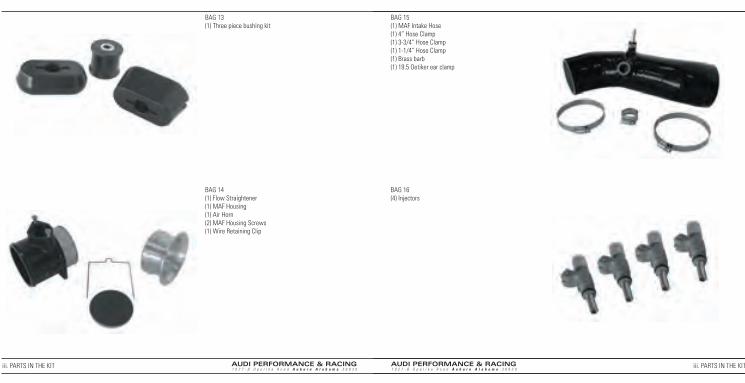
BAG 13(1) Three piece bushing kit
BAG 14(1) Flow Straightener (1) MAF Housing(1) Air Horn(2) MAF Housing Screws(1) Wire Retaining Clip
BAG 15(1) MAF Intake Hose(1) 4” Hose Clamp(1) 3-3/4” Hose Clamp(1) 1-1/4” Hose Clamp(1) Brass barb(1) 19.5 Oetiker ear clamp
BAG 16(4) Injectors
iii. PARTS IN THE KIT iii. PARTS IN THE KIT
AUDI PERFORMANCE & RACING1 0 2 7 - B O p e l i k a R o a d A u b u r n A l a b a m a 3 6 8 3 0
AUDI PERFORMANCE & RACING1 0 2 7 - B O p e l i k a R o a d A u b u r n A l a b a m a 3 6 8 3 0
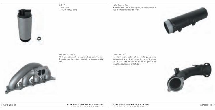
BAG 17(1) Fuel Pump(1)11.9 Oetiker ear clamp
APR Exhaust Manifold. APR’s exhaust manifold is investment cast out of Inconel. The turbo mounting studs and manifold are preassembled by APR.
Intake Crossover TubeAPR’s cast aluminum air intake pipes are powder coated to yield an attractive and durable fi nish.
Intake Elbow TubeThe elbow intake portion of the intake piping comes preassembled with a brass vacuum barb pressed into the vacuum port. Take the time to test fi t this pipe on the compressor inlet section of the turbo.
iii. PARTS IN THE KIT iii. PARTS IN THE KIT

AUDI PERFORMANCE & RACING1 0 2 7 - B O p e l i k a R o a d A u b u r n A l a b a m a 3 6 8 3 0
AUDI PERFORMANCE & RACING1 0 2 7 - B O p e l i k a R o a d A u b u r n A l a b a m a 3 6 8 3 0
Turbo DownturnAPR’s turbo downturn is investment cast in stainless steel. The downturn and exhaust mounting hardware are preassembled by APR.
Turbo ChargerThis turbo charger is specifi cally confi gured for Transverse Stage III. The wastegate and clocking have been accurately set to avoid the need of any adjustment during installation. DO NOT adjust the wastegate setting.
Exhaust DownpipeThis 3” stainless downpipe is specifi cally designed for the APR turbo downturn.
Intake Heat ShieldThe heat shield is specifi cally designed to fi t the intake pipes and withstand the ambient heat produced by the engine. This will help keep the air entering the system as cool as possible.
iii. PARTS IN THE KIT iii. PARTS IN THE KIT

AUDI PERFORMANCE & RACING1 0 2 7 - B O p e l i k a R o a d A u b u r n A l a b a m a 3 6 8 3 0
AUDI PERFORMANCE & RACING1 0 2 7 - B O p e l i k a R o a d A u b u r n A l a b a m a 3 6 8 3 0
iii. PARTS IN THE KIT
Spark PlugsThe spark plugs supplied with the kit come pregapped to the appropriate specifi cations for this application.
Boost Frequency Valve Extension CableDuring installation the BFV will be relocated.
iii. PARTS IN THE KIT
Fuel Pressure RegulatorDuring installation the 3 bar FPR will be replaced with a 4 bar FPR.

AUDI PERFORMANCE & RACING1 0 2 7 - B O p e l i k a R o a d A u b u r n A l a b a m a 3 6 8 3 0
AUDI PERFORMANCE & RACING1 0 2 7 - B O p e l i k a R o a d A u b u r n A l a b a m a 3 6 8 3 0
BEFORE YOU START
It is imperative that your car is in perfect running order before installing Stage 3. Any pre-existing problems will only be magnifi ed after install-ing Stage 3. They will also be harder to diagnose, because you will think that it is something that you did while installing Stage 3. Taking these steps seriously will make your Stage 3 install much easier, and more rewarding. Spending all weekend under a car just to have it not work at the end is very aggravating. These precautions will all but guarantee your success.The fi rst order of business is to look over the entire car. Have someone with a OBD2 interface cable, a friend or your local shop, check the engine error codes. Just because the engine light is not on does not mean that there are no error codes. If there are some, then have them investigated. If you clear them, then give them a week and make sure that they do not come back. Do not worry about misfi re codes, they are normal.Check your service intervals for things like the fuel fi lter and tranny fl uid. This would be a good chance to change your air fi lter. We suggest a K&N panel fi lter. You will be changing your oil and coolant. Make sure that you have the appropriate coolant, oil and fi lter ready and waiting. Also make sure that you are properly prepared to dispose of the used coolant, oil and fi lter according to local regulations. You will also want to make sure that the rest of the car is in good running order. For example, the clutch and brakes will be taxed by Stage 3. Take everything out of the car, you will be crawling around inside, especially in the back seat. Do not pressure wash the engine bay. Water can get into the electronic sensors and cause all manner of problems. It will be slightly easier later if you drive the tank down to ¼ full.Give yourself plenty of time to install Stage 3. Have another car available. You can easily install Stage 3 in a weekend, but if you are stressed about being able to get to work on Monday then you are likely to make mistakes and get hurt. There is always that one extra trip to the auto supply store. Last but not least, you are going to have to get your ECU to UPS! Don’t forget about that! If you already have an APR chip, then you can update your ECU with the home programmer. Otherwise, you need to take it to an authorized distributor or send it to APR before your car will run with Stage 3.You really need to have a good fl at safe place to work. Make sure that you have all of the proper safety equipment. If you will not have a friend around, make sure that you have a phone close at hand and that people will be checking in on you from time to time. Have good soap and hand cleaner, and some bottled water in case you need to rinse out your eyes. This is not a dangerous activity unless you are not prepared. Wear eye protection when under the car, or when working on the fuel system. One last thing, read the instruction manual all the way through one more time. Now you are ready.
USING TRANSVERSE STAGE 3 WITH OTHER AFTERMARKET PERFORMANCE PARTS
Please read the following section if you have any other aftermarket engine components installed on your vehicle, or if you are considering any other products to go with Stage 3. This guide should help to eliminate problems that could be caused by incompatibilities with other aftermarket components.Fuel System Components
This kit includes a larger capacity fuel pump, new 4-bar fuel pressure regulator, and larger injectors. Do not alter or substitute any of these components. Doing so will cause poor performance and other problems, and could result in severe engine damage.Spark Plugs
This kit includes new colder range spark plugs. The plugs are pre-gapped and ready to use as-is. Use only the spark plugs included with this kit. Replacement sets can be purchased from APR if you cannot fi nd them locally. Do not substitute an alternate plug. Intake Kits
None of the intake kits on the market are physically compatible with the APR Transverse Stage 3 upgrade due to the larger mass-air fl ow hous-ing. If you have removed the stock air box assembly you will need to reinstall it. The MAF, screen, air horn, and air box are all designed to work together as a system. Any modifi cations to, or omission of, any part of that system may cause issues with the tuning, drivability, and
performance of the kit.Intercoolers
An intercooler can be a worthwhile upgrade to APR’s Stage 3 turbo kit. An aftermarket intercooler can also cause issues if it is poorly designed or otherwise incompatible with the rest of the system.On these vehicles the boost pressure sender is located in the intercooler end tank. The relative position of this sender must be the same in order to work properly with a different intercooler. Also, an intercooler with excessive pressure drop could cause problems. Problems can also occur if the intercooler adds too much volume to the intake system due to excessive plumbing. The intercooler must be capable of reducing the intake charge temperature at least as effi ciently as the stock unit. An ineffi cient intercooler could cause serious performance problems or result in engine damage. Exhaust Systems
A 2.5” (or larger) exhaust system with effi cient muffl ers is an absolute requirement for the stage 3 system. The kit itself includes a 3” downpipe. The APR stage 3 catalyst and catalyst-back exhaust systems are available separately. We recommend using our exhaust system with the kit as the kit was designed around our exhaust system. Using an exhaust of different design, or an overly restrictive exhaust system could cause performance issues such as boost fl uctuations or excessive exhaust gas temperatures that could reduce component life or cause component damage. Diverter Valves (a.k.a. recirculation valves) A diverter valve is a necessary component on a modern turbocharged automotive engine. The diverter valve’s function is to release the pressur-ized intake charge during gear changes or anytime the accelerator pedal is released and the throttle plate shuts. A diverter valve recirculates the intake charge to behind the turbocharger compressor thereby reducing the stresses on the turbocharger wheels and shaft.There are a number of aftermarket alternatives to the stock Bosch diverter valve. A Bosch diverter valve is still currently the best choice in our opinion. Many of these aftermarket units suffer from fundamental design fl aws that could interfere with performance when functioning improperly. This can cause inconsistencies in performance and this problem can sometimes be diffi cult to diagnose. The Bosch diverter valve can fail as well but its’ failure is easily diagnosed.There are also some valves on the market that don’t recirculate but release the intake air to the atmosphere. These valves are commonly referred to as ‘blow-off’ valves. We do not recommend the use of a blow-off valve in place of a recirculation valve with the Stage 3 kit, or with any engine running a mass-air fl ow sensor. These valves can cause problems with the engine management that can cause inconsistencies with the fuel management learning values. This can cause the engine to run outside of the air-fuel ratios that were intended, potentially causing poor fuel economy and/or power loss or even emissions system or engine damage. Although blow-off valves may work most of the time without problems, it is not worth the risk and the performance advantages are nil. Bottom line- don’t use blow-off valves and we recommend staying with a stock-type Bosch valve until a better aftermarket solution is avail-able.Engine Management
The engine management software developed for this kit involved many man-hours of testing and development by skilled personnel and the use of highly specialized equipment and software. Do not use any software other than the software designed by APR specifi cally for this kit. Do not add any aftermarket engine management components or systems, like boost controllers or piggyback computers. Do not alter the factory engine management system, or its sensors, in any way other than we have specifi ed in this installation/owner’s manual.
iv. BEFORE YOU START iv. BEFORE YOU START

AUDI PERFORMANCE & RACING1 0 2 7 - B O p e l i k a R o a d A u b u r n A l a b a m a 3 6 8 3 0
AUDI PERFORMANCE & RACING1 0 2 7 - B O p e l i k a R o a d A u b u r n A l a b a m a 3 6 8 3 0
v. ECU REMOVAL
ECU REMOVAL
1. Ensure car is off and key is out of ignition. Engage the parking brake then remove the negative battery cable. Caution! Before disconnecting the battery, determine the correct coding for the anti-theft radio.
3. Remove factory weather-stripping.
2. Remove windshield wipers to ease the removal and installation of ECU. Use a fl at head screwdriver to remove the plastic cover from the wiper arm. Remove the wiper arms by unbolting the 13mm nut securing the wiper arms. After the nut is removed the wiper arm must be wiggled in order to remove the arm from the mount. Be sure to note the location of the wiper arm for reinstallation. Repeat this procedure for both sides.
4. Raise plastic lid over pollen fi lter.
5. Remove plastic bracket, noting location of tabs.
7. Pry back metal tab holding ECU in place with screwdriver.
6. Pull tab on wiring harness to the left, and remove left wiring harness.
8. Carefully pull ECU out away from underneath the plastic cover and rotate.
v. ECU REMOVAL

AUDI PERFORMANCE & RACING1 0 2 7 - B O p e l i k a R o a d A u b u r n A l a b a m a 3 6 8 3 0
AUDI PERFORMANCE & RACING1 0 2 7 - B O p e l i k a R o a d A u b u r n A l a b a m a 3 6 8 3 0
9. Carefully rotate ECU and pull remaining wiring harness tab. At this time the ECU needs to be sent in for APR tuning.
12. Before you start you car you must run the throttle adaptation procedure. Turn the ignition key to the ignition ON position but do not start the car. Leave the key in this position for three minutes. This will allow the ECU to relearn the relative throttle positions and prevent possible error codes.
10. After you complete the kit installation you will reinstall your APR tuned ECU. Attach all electrical plugs to the ECU ensuring that the plugs are fully seated and that the release mechanisms are pushed all the way in.
v. ECU REMOVAL
1. Secure the vehicle on a lift. Although it is not impossible to install this kit with something other than a lift, you would hate yourself for trying about half way through the install.
vi. INSTALLATION PROCEDURE
INSTALLATION PROCEDURE
2. Disconnect the negative battery terminal.
TOOLS NEEDED: 10mm wrench

AUDI PERFORMANCE & RACING1 0 2 7 - B O p e l i k a R o a d A u b u r n A l a b a m a 3 6 8 3 0
AUDI PERFORMANCE & RACING1 0 2 7 - B O p e l i k a R o a d A u b u r n A l a b a m a 3 6 8 3 0
vi. INSTALLATION PROCEDURE
3. Lift vehicle and remove the passenger front tire.
4. Remove tie rod end.
5. Remove CV shaft nut.
6. Remove CV shaft heat shield.
vi. INSTALLATION PROCEDURE
TOOLS NEEDED: 17mm lug socket
TOOLS NEEDED: 19mm socket
TOOLS NEEDED: 12point 30mm socket
TOOLS NEEDED: 16mm wrench

AUDI PERFORMANCE & RACING1 0 2 7 - B O p e l i k a R o a d A u b u r n A l a b a m a 3 6 8 3 0
AUDI PERFORMANCE & RACING1 0 2 7 - B O p e l i k a R o a d A u b u r n A l a b a m a 3 6 8 3 0
7. Remove inner CV shaft bolts.
8. Gently drive outer CV shaft end back through hub assembly, taking care not to damage threads.
9. Loosen ball joint nut and pry lower control arm down out of spindle assembly. Remove CV shaft, being careful not to tear boots on any sharp edges..
10. Drain coolant and oil. Not all coolant will drain from car.
TOOLS NEEDED: #10 3box socket (a.k.a. triple square or 12 point)
TOOLS NEEDED: Brass punch and a hammer
TOOLS NEEDED: 18mm wrench and pry bar
COOLANT
OILTOOLS NEEDED: OIL-19mm wrench COOLANT-8mm allen
vi. INSTALLATION PROCEDURE vi. INSTALLATION PROCEDURE

AUDI PERFORMANCE & RACING1 0 2 7 - B O p e l i k a R o a d A u b u r n A l a b a m a 3 6 8 3 0
AUDI PERFORMANCE & RACING1 0 2 7 - B O p e l i k a R o a d A u b u r n A l a b a m a 3 6 8 3 0
11. Remove lower oil return line at oil pan.
12. Remove O2 sensor plug cover and disconnect plugs. Remove O2 sensors from exhaust.
13. Remove downpipe hardware.
14. Remove exhaust mounting bracket spanning fl oor-pan and remove downpipe.
TOOLS NEEDED: 10mm wrench
TOOLS NEEDED: 10mm socket and a 22mm oxygen sensor socket
TOOLS NEEDED: 17mm socket
TOOLS NEEDED: 13mm socket
vi. INSTALLATION PROCEDURE vi. INSTALLATION PROCEDURE

AUDI PERFORMANCE & RACING1 0 2 7 - B O p e l i k a R o a d A u b u r n A l a b a m a 3 6 8 3 0
AUDI PERFORMANCE & RACING1 0 2 7 - B O p e l i k a R o a d A u b u r n A l a b a m a 3 6 8 3 0
15. Remove the turbo support bracket’s lower hardware.
16. Remove bolts on turbo exit tube as indicated in picture.
17. Unsnap heat shielding around the turbo exit to pancake pipe hose and loosen clamp.
18. Remove bolt on bracket behind turbo exit tube as indicated in picture and remove bracket. Then remove hose.
TOOLS NEEDED: 6mm allen
TOOLS NEEDED: 13mm socketTOOLS NEEDED: 8mm and 10mm socket
vi. INSTALLATION PROCEDURE vi. INSTALLATION PROCEDURE

AUDI PERFORMANCE & RACING1 0 2 7 - B O p e l i k a R o a d A u b u r n A l a b a m a 3 6 8 3 0
AUDI PERFORMANCE & RACING1 0 2 7 - B O p e l i k a R o a d A u b u r n A l a b a m a 3 6 8 3 0
19. Remove intake to compressor housing bolts.
20. Remove engine cover. Twist each screw 1/4 turn and pull engine cover up off of engine.
21. Remove air pump line at air box. Squeeze ribbed section of connector on both sides and pull off.
22. Remove MAF sensor plug. Depress tab with thumb nail and pull connector off.
TOOLS NEEDED: 5mm allen
TOOLS NEEDED: Large fl at head screw driver
vi. INSTALLATION PROCEDURE vi. INSTALLATION PROCEDURE

AUDI PERFORMANCE & RACING1 0 2 7 - B O p e l i k a R o a d A u b u r n A l a b a m a 3 6 8 3 0
AUDI PERFORMANCE & RACING1 0 2 7 - B O p e l i k a R o a d A u b u r n A l a b a m a 3 6 8 3 0
23. Remove intake hose at MAF housing end.
24. Loosen air-box screws.
25. Remove air-box lid.
26. Remove boost frequency valve plug.
TOOLS NEEDED: #2 Phillips
TOOLS NEEDED: #2 Phillips
vi. INSTALLATION PROCEDURE vi. INSTALLATION PROCEDURE

AUDI PERFORMANCE & RACING1 0 2 7 - B O p e l i k a R o a d A u b u r n A l a b a m a 3 6 8 3 0
AUDI PERFORMANCE & RACING1 0 2 7 - B O p e l i k a R o a d A u b u r n A l a b a m a 3 6 8 3 0
27. Remove both DV (diverter valve) ear clamps and remove vacuum line on top.
28. Remove spring clamp on boost frequency valve and remove from hose.
29. Remove ear clamp on oil breather valve and remove from intake hose.
30. Pry back retaining clip from intake hose at aluminum pipe and remove hose.
TOOLS NEEDED: Side cutters
TOOLS NEEDED: Pliers
TOOLS NEEDED: Side cutters
TOOLS NEEDED: Screw driver
PRY HERE
vi. INSTALLATION PROCEDURE vi. INSTALLATION PROCEDURE

AUDI PERFORMANCE & RACING1 0 2 7 - B O p e l i k a R o a d A u b u r n A l a b a m a 3 6 8 3 0
AUDI PERFORMANCE & RACING1 0 2 7 - B O p e l i k a R o a d A u b u r n A l a b a m a 3 6 8 3 0
31. Remove all ear clamps from the boost frequency valve, taking care not to damage the plastic nipples.
32. Remove cloth heat shield.
33. Remove hose clamps and hose at intake side of turbo.
34. Remove two bolts on clip retaining remaining tubing assembly and pull tubing assembly out of car.
TOOLS NEEDED: Side cutters TOOLS NEEDED: Stubby fl at head screw driver
TOOLS NEEDED: 10mm socket
vi. INSTALLATION PROCEDURE vi. INSTALLATION PROCEDURE

AUDI PERFORMANCE & RACING1 0 2 7 - B O p e l i k a R o a d A u b u r n A l a b a m a 3 6 8 3 0
AUDI PERFORMANCE & RACING1 0 2 7 - B O p e l i k a R o a d A u b u r n A l a b a m a 3 6 8 3 0
35. Remove heat shield and lower clamp. Retain shield and two 13mm bolts for reinstallation.
36. Remove aluminum intake pipe at turbo.
37. Remove spring clamp and vacuum line from aluminum intake pipe. Remove pipe from vehicle.
38. Remove spring clamp from upper coolant line and remove coolant line taking care not to damage the plastic Y adaptor.
TOOLS NEEDED: 13mm socket TOOLS NEEDED: Pliers
TOOLS NEEDED: Pliers
vi. INSTALLATION PROCEDURE vi. INSTALLATION PROCEDURE

AUDI PERFORMANCE & RACING1 0 2 7 - B O p e l i k a R o a d A u b u r n A l a b a m a 3 6 8 3 0
AUDI PERFORMANCE & RACING1 0 2 7 - B O p e l i k a R o a d A u b u r n A l a b a m a 3 6 8 3 0
39. Remove turbo to manifold bolts. Allow turbo to sag in order to reach rear of oil feed line.
40. Remove front oil feed line bolts.
41. Remove rear oil feed line bolt.
42. Cut wide retaining band and remove vacuum line routed to wastegate actuator.
TOOLS NEEDED: 17mm socket and wrench
TOOLS NEEDED: 8mm allen
TOOLS NEEDED: 5mm allen
TOOLS NEEDED: Utility knife
vi. INSTALLATION PROCEDURE vi. INSTALLATION PROCEDURE

AUDI PERFORMANCE & RACING1 0 2 7 - B O p e l i k a R o a d A u b u r n A l a b a m a 3 6 8 3 0
AUDI PERFORMANCE & RACING1 0 2 7 - B O p e l i k a R o a d A u b u r n A l a b a m a 3 6 8 3 0
43. Remove turbo.
44. Remove small front engine cover.
45. Remove bracket assembly from intake to access fi nal oil line bracket.
46. Loosen fi nal oil line allen head bolt and remove with a magnetic retrieval tool. The bolt can be seen from the driver’s side as illustrated but removed from the front. Remove oil line towards the back of the motor.
TOOLS NEEDED: Large fl at head screw driver
TOOLS NEEDED: 10mm socket and 5mm allen
TOOLS NEEDED: ½ inch drive, 6mm stubby
vi. INSTALLATION PROCEDURE vi. INSTALLATION PROCEDURE

AUDI PERFORMANCE & RACING1 0 2 7 - B O p e l i k a R o a d A u b u r n A l a b a m a 3 6 8 3 0
AUDI PERFORMANCE & RACING1 0 2 7 - B O p e l i k a R o a d A u b u r n A l a b a m a 3 6 8 3 0
47. Reattach bracket assembly to front of intake.
48. Raise vehicle and remove thirteen manifold bolts. Keep all washers for reinstallation. Remove exhaust manifold and gasket.
49. Install exhaust manifold gasket from BAG 1 and then install APR exhaust manifold. Install saved exhaust manifold washers.
50. Install 13 copper fl ange nuts from BAG 1 onto exhaust manifold studs.
TOOLS NEEDED: 10mm socket and 5mm allen
TOOLS NEEDED: 12mm swivel socket TOOLS NEEDED: 12mm swivel socket and 12mm stubbyTORQUE SPECIFICATION: 25nm/19ft-lbs
vi. INSTALLATION PROCEDURE vi. INSTALLATION PROCEDURE
AUDI PERFORMANCE & RACING1 0 2 7 - B O p e l i k a R o a d A u b u r n A l a b a m a 3 6 8 3 0
AUDI PERFORMANCE & RACING1 0 2 7 - B O p e l i k a R o a d A u b u r n A l a b a m a 3 6 8 3 0
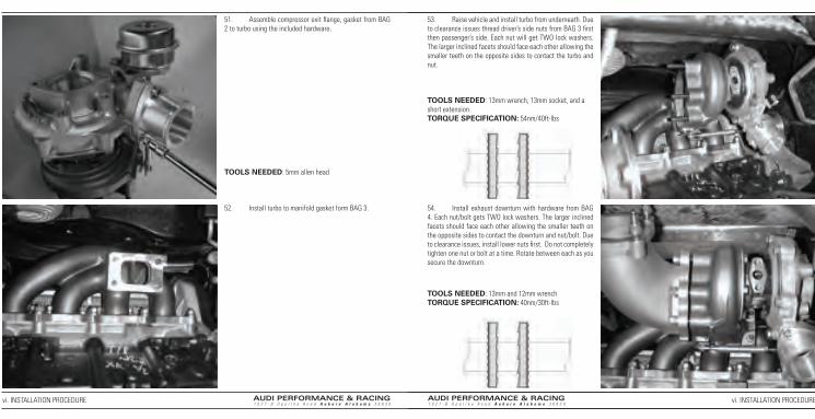
51. Assemble compressor exit fl ange, gasket from BAG 2 to turbo using the included hardware.
52. Install turbo to manifold gasket form BAG 3.
53. Raise vehicle and install turbo from underneath. Due to clearance issues thread driver’s side nuts from BAG 3 fi rst then passenger’s side. Each nut will get TWO lock washers. The larger inclined facets should face each other allowing the smaller teeth on the opposite sides to contact the turbo and nut.
54. Install exhaust downturn with hardware from BAG 4. Each nut/bolt gets TWO lock washers. The larger inclined facets should face each other allowing the smaller teeth on the opposite sides to contact the downturn and nut/bolt. Due to clearance issues, install lower nuts fi rst. Do not completely tighten one nut or bolt at a time. Rotate between each as you secure the downturn.
TOOLS NEEDED: 5mm allen head
TOOLS NEEDED: 13mm wrench, 13mm socket, and a short extension.TORQUE SPECIFICATION: 54nm/40ft-lbs
TOOLS NEEDED: 13mm and 12mm wrenchTORQUE SPECIFICATION: 40nm/30ft-lbs
vi. INSTALLATION PROCEDURE vi. INSTALLATION PROCEDURE

AUDI PERFORMANCE & RACING1 0 2 7 - B O p e l i k a R o a d A u b u r n A l a b a m a 3 6 8 3 0
AUDI PERFORMANCE & RACING1 0 2 7 - B O p e l i k a R o a d A u b u r n A l a b a m a 3 6 8 3 0
55. Remove 10mm nut securing pancake pipe.
56. Install compressor exit and included hardware from BAG 5 on compressor side fi rst. Leave clamps loose for adjustment.
57. Remove O-ring from BAG 6 and apply O-ring assembly lube. Install O-ring into groove in elbow intake pipe.
58. Install elbow intake pipe with hardware and phenolic spacer from BAG 6 onto compressor side of turbo. Install as illustrated from top of motor. Only tighten bolts fi nger tight at this point.
TOOLS NEEDED: 10mm socket
TOOLS NEEDED: Flat head screwdriver
vi. INSTALLATION PROCEDURE vi. INSTALLATION PROCEDURE
AUDI PERFORMANCE & RACING1 0 2 7 - B O p e l i k a R o a d A u b u r n A l a b a m a 3 6 8 3 0
AUDI PERFORMANCE & RACING1 0 2 7 - B O p e l i k a R o a d A u b u r n A l a b a m a 3 6 8 3 0
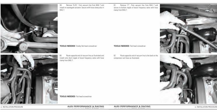
59. Remove 15.25”, 7mm vacuum line from BAG 7 and install on wastegate actuator. Secure with hose clamp also in BAG 7.
60. Route opposite end of vacuum line as illustrated and install onto short nipple of boost frequency valve with hose clamp from BAG 7.
61. Remove 17”, 7mm vacuum line from BAG 7 and secure to bottom nipple of boost frequency valve with hose clamp from BAG 7.
62. Route opposite end of vacuum line to the barb on the compressor exit hose as illustrated.
TOOLS NEEDED: Stubby fl at head screwdriver
TOOLS NEEDED: Flat head screwdriver
TOOLS NEEDED: Flat head screwdriver
vi. INSTALLATION PROCEDURE vi. INSTALLATION PROCEDURE
AUDI PERFORMANCE & RACING1 0 2 7 - B O p e l i k a R o a d A u b u r n A l a b a m a 3 6 8 3 0
AUDI PERFORMANCE & RACING1 0 2 7 - B O p e l i k a R o a d A u b u r n A l a b a m a 3 6 8 3 0
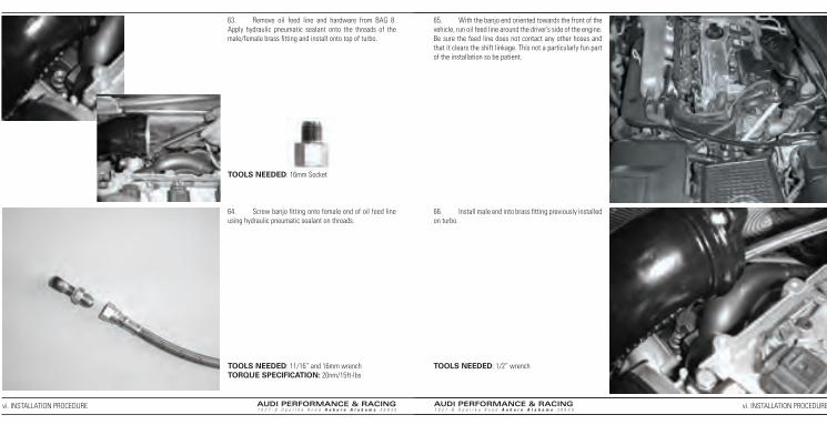
63. Remove oil feed line and hardware from BAG 8. Apply hydraulic pneumatic sealant onto the threads of the male/female brass fi tting and install onto top of turbo.
64. Screw banjo fi tting onto female end of oil feed line using hydraulic pneumatic sealant on threads.
65. With the banjo end oriented towards the front of the vehicle, run oil feed line around the driver’s side of the engine. Be sure the feed line does not contact any other hoses and that it clears the shift linkage. This not a particularly fun part of the installation so be patient.
66. Install male end into brass fi tting previously installed on turbo.
TOOLS NEEDED: 16mm Socket
TOOLS NEEDED: 11/16” and 16mm wrenchTORQUE SPECIFICATION: 20nm/15ft-lbs
TOOLS NEEDED: 1/2” wrench
vi. INSTALLATION PROCEDURE vi. INSTALLATION PROCEDURE

AUDI PERFORMANCE & RACING1 0 2 7 - B O p e l i k a R o a d A u b u r n A l a b a m a 3 6 8 3 0
AUDI PERFORMANCE & RACING1 0 2 7 - B O p e l i k a R o a d A u b u r n A l a b a m a 3 6 8 3 0
67. Assemble banjo fi tting as illustrated and install onto front of engine. Keep oil feed line away from coolant line.
68. Trim heat shield as illustrated.
69. Install both oil feed line clamps from BAG 8 as illustrated.
70. Reinstall heat shield and secure one oil feed line clamp. Use the two 13mm bolts that were removed earlier. Passenger’s side bolt holds both heat shield and one oil feed line clamp. Driver’s side bolt holds only the heat shield.
TOOLS NEEDED: 17mm socket
TOOLS NEEDED: There are a number of tools you could use but tin snips work fi ne.
TOOLS NEEDED: 13mm wrench
vi. INSTALLATION PROCEDURE vi. INSTALLATION PROCEDURE

AUDI PERFORMANCE & RACING1 0 2 7 - B O p e l i k a R o a d A u b u r n A l a b a m a 3 6 8 3 0
AUDI PERFORMANCE & RACING1 0 2 7 - B O p e l i k a R o a d A u b u r n A l a b a m a 3 6 8 3 0
71. Remove 19” vacuum line from BAG 7 and install on brass barb in elbow intake pipe with hose clamp from same bag.
72. Remove heat shielding from vacuum line as illustrated.
73. Remove vacuum line from both plastic clips as illustrated.
74. Loosen spring clamp and remove vacuum line from vehicle keeping spring clamp for reinstallation.
TOOLS NEEDED: Flat head stubby screwdriver
TOOLS NEEDED: Pliers
vi. INSTALLATION PROCEDURE vi. INSTALLATION PROCEDURE
AUDI PERFORMANCE & RACING1 0 2 7 - B O p e l i k a R o a d A u b u r n A l a b a m a 3 6 8 3 0
AUDI PERFORMANCE & RACING1 0 2 7 - B O p e l i k a R o a d A u b u r n A l a b a m a 3 6 8 3 0
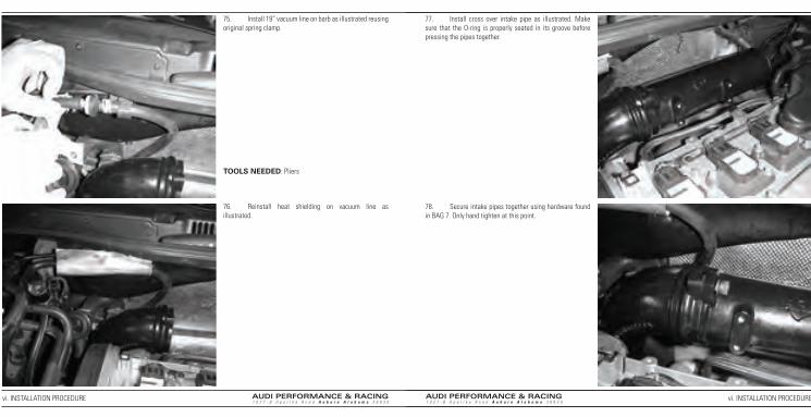
75. Install 19” vacuum line on barb as illustrated reusing original spring clamp.
76. Reinstall heat shielding on vacuum line as illustrated.
77. Install cross over intake pipe as illustrated. Make sure that the O-ring is properly seated in its groove before pressing the pipes together.
78. Secure intake pipes together using hardware found in BAG 7. Only hand tighten at this point.
TOOLS NEEDED: Pliers
vi. INSTALLATION PROCEDURE vi. INSTALLATION PROCEDURE

AUDI PERFORMANCE & RACING1 0 2 7 - B O p e l i k a R o a d A u b u r n A l a b a m a 3 6 8 3 0
AUDI PERFORMANCE & RACING1 0 2 7 - B O p e l i k a R o a d A u b u r n A l a b a m a 3 6 8 3 0
79. Install intake heat shield over intake pipe assembly with the refl ective side out. The two elongated holes in the heat shield will line up with the fl at sections on the straight intake pipe.
80. Install intake mounting brackets found in BAG 9. Only hand tighten at this time to allow for adjustment. Passenger’s side bracket also secures the remaining oil feed line clip.
81. Rotate intake pipe until the fl at surfaces on the intake pipe are fl ush with the adjacent surfaces on the mounting brackets.
82. Fold back heat shield and tighten both 6mm allen head bolts securing intake pipes.
TOOLS NEEDED: 5mm allen TOOLS NEEDED: 6mm allen
vi. INSTALLATION PROCEDURE vi. INSTALLATION PROCEDURE

AUDI PERFORMANCE & RACING1 0 2 7 - B O p e l i k a R o a d A u b u r n A l a b a m a 3 6 8 3 0
AUDI PERFORMANCE & RACING1 0 2 7 - B O p e l i k a R o a d A u b u r n A l a b a m a 3 6 8 3 0
83. Remove upper DV hose from BAG 10 and install as illustrated using large hose clamp found in same the bag.
84. Install diverter valve in upper DV hose with small hose clamp found in BAG 10.
85. Route lower DV hose with barb down to barb on compressor exit hose and then install opposite end onto diverter valve with hose clamp from BAG 10
86. Insure that the fl at surfaces on the intake pipe are fl ush with the adjacent surfaces on the mounting brackets. Lift vehicle and tighten 6mm allen head bolts on elbow intake pipe to compressor housing.
87. Insert lower DV hose onto the one inch port of the compressor exit hose and secure with clamp found in BAG 5. It may help to apply O-ring assembly lube to the barb to aid in installation.
88. Tighten upper and lower hose clamps on compressor exit hose.
Since it is very diffi cult to take a useful image of this area of the installation we thought a Transverse Stage III logo would be a good place holder.
TOOLS NEEDED: Flat head screwdriver
TOOLS NEEDED: Flat head screwdriver
TOOLS NEEDED: Flat head screwdriver
vi. INSTALLATION PROCEDURE vi. INSTALLATION PROCEDURE

AUDI PERFORMANCE & RACING1 0 2 7 - B O p e l i k a R o a d A u b u r n A l a b a m a 3 6 8 3 0
AUDI PERFORMANCE & RACING1 0 2 7 - B O p e l i k a R o a d A u b u r n A l a b a m a 3 6 8 3 0
89. Reinstall 10mm nut securing pancake pipe.
90. Reinstall CV shaft in reverse order of removal using medium strength thread lock compound on inner CV shaft bolts.
91. Reinstall tire.
92. Remove long coolant hose from BAG 11 and install onto engine side of turbo.
TOOLS NEEDED: 10mm socket
TOOLS NEEDED: #10 3box socket (12 point)TORQUE SPECIFICATION: 40nm/30ft-lbs
TOOLS NEEDED: 17mm lug socketTORQUE SPECIFICATION: 85ft-lbs
TOOLS NEEDED: 19mm socket
vi. INSTALLATION PROCEDURE vi. INSTALLATION PROCEDURE

AUDI PERFORMANCE & RACING1 0 2 7 - B O p e l i k a R o a d A u b u r n A l a b a m a 3 6 8 3 0
AUDI PERFORMANCE & RACING1 0 2 7 - B O p e l i k a R o a d A u b u r n A l a b a m a 3 6 8 3 0
93. Remove short coolant hose and hardware from BAG 11 and install on fi rewall side of turbo.
94. Install opposite end of hose to the engine block routing it underneath CV shaft as illustrated. Align hose so that it dose not contact CV shaft. At full suspension droop, hose may be near CV shaft but will not pose a problem when suspension is under normal load.
95. Route opposite end of long coolant line around intake elbow to front of engine as illustrated. Set aside the hose clamp supplied with this hose. It will be installed later.
96. Remove oil drain line from BAG 12.
TOOLS NEEDED: 19mm socket
TOOLS NEEDED: 19mm socket OIL PAN TURBO
vi. INSTALLATION PROCEDURE vi. INSTALLATION PROCEDURE

AUDI PERFORMANCE & RACING1 0 2 7 - B O p e l i k a R o a d A u b u r n A l a b a m a 3 6 8 3 0
AUDI PERFORMANCE & RACING1 0 2 7 - B O p e l i k a R o a d A u b u r n A l a b a m a 3 6 8 3 0
97. Install male oil drain line return fl ange and gasket to original oil return location on oil pan.
98. Install fl anged end of oil return line, gasket and hardware to the bottom side of the turbo as illustrated.
99. Apply hydraulic pneumatic sealant to drain line return fl ange and screw on oil drain line. To keep from kinking the line, install as illustrated.
100. Remove 4 bolts from motor mount. There are two 13mm bolts and two 16mm bolts. Take note of which bolt is installed where for reinstallation.
TOOLS NEEDED: 5mm allenTORQUE SPECIFICATION: 10nm/7ft-lbs
TOOLS NEEDED: 6mm allenTORQUE SPECIFICATION: 10nm/7ft-lbs
TOOLS NEEDED: 13/16” and 1” wrench. Tighten nut until it is fully seated and then tighten an additional 1/2 turn. Do not excessively tighten
TOOLS NEEDED: 13mm and 16mm socket
vi. INSTALLATION PROCEDURE vi. INSTALLATION PROCEDURE

AUDI PERFORMANCE & RACING1 0 2 7 - B O p e l i k a R o a d A u b u r n A l a b a m a 3 6 8 3 0
AUDI PERFORMANCE & RACING1 0 2 7 - B O p e l i k a R o a d A u b u r n A l a b a m a 3 6 8 3 0
101. Remove motor mount by pulling toward the front of the engine. Engine may shift when you remove the motor mount.
102. Remove 16mm bolt on end of motor mount.
103. Disassemble the motor mount as illustrated.
104. Replace the original bushings with the bushings in BAG 13 and reinstall. When assembling, pay attention to the ribs on the motor mount for registration.
TOOLS NEEDED: 16mm socket TOOLS NEEDED: 13mm and 16mm socket
vi. INSTALLATION PROCEDURE vi. INSTALLATION PROCEDURE
AUDI PERFORMANCE & RACING1 0 2 7 - B O p e l i k a R o a d A u b u r n A l a b a m a 3 6 8 3 0
AUDI PERFORMANCE & RACING1 0 2 7 - B O p e l i k a R o a d A u b u r n A l a b a m a 3 6 8 3 0
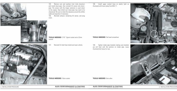
105. Remove nuts and washers from turbo downturn and install down-pipe. Also reinstall O2 sensor onto down-pipe. The sensor with the longer extension is used closer to the engine. Heat shield over down-pipe may need to be clearanced. Be sure to check the clearance around the shifter cable and reposition if necessary.106. Reinstall exhaust, remaining O2 sensor, and plug cover.
107. Reinstall CV shaft heat shield and lower vehicle.
108. Install upper coolant hose on plastic barb as illustrated with hose clamp from BAG 11.
109. Tighten intake pipe brackets making sure brackets are still fl ush with fl at sections on intake pipe. Leave illustrated bolt loose for now.
TOOLS NEEDED: 7/16” 12point socket and a 22mm wrench
TOOLS NEEDED: 16mm socket
TOOLS NEEDED: Flat head screwdriver
TOOLS NEEDED: 5mm allen
vi. INSTALLATION PROCEDURE vi. INSTALLATION PROCEDURE

AUDI PERFORMANCE & RACING1 0 2 7 - B O p e l i k a R o a d A u b u r n A l a b a m a 3 6 8 3 0
AUDI PERFORMANCE & RACING1 0 2 7 - B O p e l i k a R o a d A u b u r n A l a b a m a 3 6 8 3 0
110. Remove the original air horn from the lid of the air box. Pry back clip with fl at head screwdriver and pull off air horn.
111. Remove two screws securing the original MAF housing and remove the housing from the air box lid. Remove the MAF sensor from the MAF housing and retain for reinstallation
112. Modify air-box by removing material as illustrated. Only the tabs need to be removed and made fl ush with the inside surface. The overall hole does not need to be enlarged. The stock air box must be used, and only with these modifi cations. You may modify the factory cold air intake that feeds the air box. However, cone intakes and other aftermarket intake modifi cations are not approved for use with this kit.
113. Remove the MAF/air-horn assembly from BAG 14 and install in air-box lid as illustrated. Secure the APR MAF housing to the air box using the original screws fi rst. Next place the fl ow straightener in the air horn and secure them to the MAF housing with the wire clip. The small bent section on the wire clip locks into the air box cover. Be careful not to let the fl ow straightener vanes get bent. Secure the original MAF sensor to the APR MAF housing with the screws provided in the housing.
DO NOT LEAVE OUT THE FLOW STRAIGHTENER!!! The fl ow straightener is a critical part of the design and the tuning, all warranties and promised performance are invalid if the fl ow straightener is not installed. If you damage it, a replacement is available for a nominal fee.
TOOLS NEEDED: Flat head screwdriver
TOOLS NEEDED: Phillips head screwdriver TOOLS NEEDED: Phillips head screwdriver
vi. INSTALLATION PROCEDURE vi. INSTALLATION PROCEDURE

AUDI PERFORMANCE & RACING1 0 2 7 - B O p e l i k a R o a d A u b u r n A l a b a m a 3 6 8 3 0
AUDI PERFORMANCE & RACING1 0 2 7 - B O p e l i k a R o a d A u b u r n A l a b a m a 3 6 8 3 0
114. Reinstall air-box lid onto air-box and then connect air pump line. A K&N fi lter is suggested, do not oil it heavily. Foam fi lters are not approved for use with this kit. They use too much oil, which coats the MAF sensor and can lead to serious running problems.
115. Reconnect MAF sensor.
116. Remove hose clamps and MAF intake hose from BAG 15 and install loosely onto hose. Then install MAF intake hose between MAF housing and intake pipe and tighten down hose clamps. Make sure the hose clamps are on the correct ends. The larger of the two clamps is intended for the MAF side of the hose.
117. Install the oil breather valve onto the MAF hose with the small hose clamp supplied in BAG 15.
TOOLS NEEDED: Phillips head screwdriver TOOLS NEEDED: Flat head screwdriver
TOOLS NEEDED: Flat head screwdriver
vi. INSTALLATION PROCEDURE vi. INSTALLATION PROCEDURE

AUDI PERFORMANCE & RACING1 0 2 7 - B O p e l i k a R o a d A u b u r n A l a b a m a 3 6 8 3 0
AUDI PERFORMANCE & RACING1 0 2 7 - B O p e l i k a R o a d A u b u r n A l a b a m a 3 6 8 3 0
118. Snap the heat shielding around the intake pipes. There will be a total of six snaps.
119. Remove the 30”- 7mm vacuum line and two hose clamps from BAG 7 and route as illustrated. Secure one end to the MAF intake hose and the opposite end to the boost frequency valve.
120. Remove 10mm bolt securing charcoal canister and rotate out of way as illustrated.
121. Cut ear clamp and remove original DV vacuum line.
TOOLS NEEDED: Flat head screwdriver
TOOLS NEEDED: 10mm socket
TOOLS NEEDED: Side cutters
vi. INSTALLATION PROCEDURE vi. INSTALLATION PROCEDURE

AUDI PERFORMANCE & RACING1 0 2 7 - B O p e l i k a R o a d A u b u r n A l a b a m a 3 6 8 3 0
AUDI PERFORMANCE & RACING1 0 2 7 - B O p e l i k a R o a d A u b u r n A l a b a m a 3 6 8 3 0
122. Remove stepped vacuum line from BAG 7 and install the 7mm end onto the DV tubing as illustrated and tighten clamp.
123. Install the 5mm end of the stepped vacuum line to the DV vacuum nipple. Secure vacuum line with an ear clamp supplied in BAG 7. If you do not have the correct tool to tighten the ear clamp, a pair of side cutters will be a good substitute.
124. Plug extension cable into relocated boost frequency valve and then to original plug.
125. Put the strap found in BAG 7 around the stepped vacuum line and the extension cable.
TOOLS NEEDED: Flat head screwdriver
TOOLS NEEDED: Ear clamp crimping tool
vi. INSTALLATION PROCEDURE vi. INSTALLATION PROCEDURE

AUDI PERFORMANCE & RACING1 0 2 7 - B O p e l i k a R o a d A u b u r n A l a b a m a 3 6 8 3 0
AUDI PERFORMANCE & RACING1 0 2 7 - B O p e l i k a R o a d A u b u r n A l a b a m a 3 6 8 3 0
126. Secure the strap to the mounting bracket as illustrated. Be sure not to crimp the vacuum line.
127. Remove three 5mm bolts retaining charcoal canister bracket and remove bracket.
128. Disconnect all coil pack plugs from coil packs. Push the connector in, carefully depress the trigger with your thumbnail, and gently slide it back.
129. Remove all bolts securing coil packs then remove coil packs and spark plugs.
TOOLS NEEDED: 5mm allen
TOOLS NEEDED: 5mm socket TOOLS NEEDED: 5mm allen, 5/8” spark plug socket, and long extension
vi. INSTALLATION PROCEDURE vi. INSTALLATION PROCEDURE

AUDI PERFORMANCE & RACING1 0 2 7 - B O p e l i k a R o a d A u b u r n A l a b a m a 3 6 8 3 0
AUDI PERFORMANCE & RACING1 0 2 7 - B O p e l i k a R o a d A u b u r n A l a b a m a 3 6 8 3 0
130. Install four new spark plugs supplied with the kit. The new spark plugs are pre-gapped to the appropriate specifi cations. Make sure that the little metal cap is snug on the top of the spark plug.
131. Reinstall coil packs and reconnect all coil pack plugs.
132. Reinstall charcoal canister bracket.
133. Reinstall charcoal canister making sure to register clip in back.
TOOLS NEEDED: 5/8” socket, and long extensionTORQUE SPECIFICATION: 30nm/22ft-lbs
TOOLS NEEDED: 5mm allen
TOOLS NEEDED: 5mm allen
TOOLS NEEDED: 5mm allen
vi. INSTALLATION PROCEDURE vi. INSTALLATION PROCEDURE

AUDI PERFORMANCE & RACING1 0 2 7 - B O p e l i k a R o a d A u b u r n A l a b a m a 3 6 8 3 0
AUDI PERFORMANCE & RACING1 0 2 7 - B O p e l i k a R o a d A u b u r n A l a b a m a 3 6 8 3 0
134. Remove gas cap to relieve fuel system pressure.
135. Remove wiring harness from injectors by squeezing tabs.
136. Gently pull back tabs on the wiring harness attached to the fuel rail and remove toward front of engine. Pay special attention not to break tabs.
137. Remove 5mm allen head bolts retaining fuel rail, making sure not to drop the bolts.
TOOLS NEEDED: 5mm allen
vi. INSTALLATION PROCEDURE vi. INSTALLATION PROCEDURE

AUDI PERFORMANCE & RACING1 0 2 7 - B O p e l i k a R o a d A u b u r n A l a b a m a 3 6 8 3 0
AUDI PERFORMANCE & RACING1 0 2 7 - B O p e l i k a R o a d A u b u r n A l a b a m a 3 6 8 3 0
138. Wear eye protection while working with fuel system. Before removing fuel rail, clean around injector bases with compressed air to prevent accidental contamination. Pull fuel rail up and out of injector sockets.
139. Remove injector retaining clips as illustrated.
140. Remove injectors as illustrated. Check fuel rail for any possible O-rings that may have stuck in place. Some gas will spill from fuel rail. Keep any possible ignition source away from fuel rail.
141. Remove new injectors from BAG 16 and install into fuel rail. Be sure that they are aligned properly.
vi. INSTALLATION PROCEDURE vi. INSTALLATION PROCEDURE

AUDI PERFORMANCE & RACING1 0 2 7 - B O p e l i k a R o a d A u b u r n A l a b a m a 3 6 8 3 0
AUDI PERFORMANCE & RACING1 0 2 7 - B O p e l i k a R o a d A u b u r n A l a b a m a 3 6 8 3 0
142. Reinstall the clips that hold them to the fuel rail.
143. Align injectors with sockets and press down until injectors pop in place.
144. Replace two fuel rail retaining bolts being careful not to drop them.
145. Put wiring harness back onto fuel rail making sure not to break retaining clips.
TOOLS NEEDED: 5mm allen
vi. INSTALLATION PROCEDURE vi. INSTALLATION PROCEDURE

AUDI PERFORMANCE & RACING1 0 2 7 - B O p e l i k a R o a d A u b u r n A l a b a m a 3 6 8 3 0
AUDI PERFORMANCE & RACING1 0 2 7 - B O p e l i k a R o a d A u b u r n A l a b a m a 3 6 8 3 0
146. Plug wiring harness back on to injectors.
147. Cut off ear clamp on fuel pressure regulator and remove hose.
148. Remove retaining clip and fuel pressure regulator.
149. Install new fuel pressure regulator. Push down fi rmly until completely seated.
TOOLS NEEDED: Side cutters
TOOLS NEEDED: Pliers
vi. INSTALLATION PROCEDURE vi. INSTALLATION PROCEDURE

AUDI PERFORMANCE & RACING1 0 2 7 - B O p e l i k a R o a d A u b u r n A l a b a m a 3 6 8 3 0
AUDI PERFORMANCE & RACING1 0 2 7 - B O p e l i k a R o a d A u b u r n A l a b a m a 3 6 8 3 0
150. Reinstall fuel pressure regulator retaining clip.
151. Reinstall vacuum line and secure with an ear clamp supplied in BAG 7.
152. Reinstall lower engine cover.
153. Reinstall upper engine cover.
TOOLS NEEDED: Ear clamp crimping tool
TOOLS NEEDED: Large fl at head screwdriver
TOOLS NEEDED: Large fl at head screwdriver
vi. INSTALLATION PROCEDURE vi. INSTALLATION PROCEDURE

AUDI PERFORMANCE & RACING1 0 2 7 - B O p e l i k a R o a d A u b u r n A l a b a m a 3 6 8 3 0
AUDI PERFORMANCE & RACING1 0 2 7 - B O p e l i k a R o a d A u b u r n A l a b a m a 3 6 8 3 0
154. Remove passenger side rear seat base.
155. Remove three screws retaining fuel pump access door.
156. Disconnect plug on fuel pump assembly. Push the connector in, carefully depress the trigger with your thumbnail, and gently slide it back.
157. By depressing retaining clip with a screwdriver, disconnect fuel feed and return lines from assembly making note of which line connects to which port for reinstallation.
TOOLS NEEDED: Phillips head screwdriver TOOLS NEEDED: Flat head screwdriver
vi. INSTALLATION PROCEDURE vi. INSTALLATION PROCEDURE

AUDI PERFORMANCE & RACING1 0 2 7 - B O p e l i k a R o a d A u b u r n A l a b a m a 3 6 8 3 0
AUDI PERFORMANCE & RACING1 0 2 7 - B O p e l i k a R o a d A u b u r n A l a b a m a 3 6 8 3 0
158. Unscrew pump assembly retaining ring.
159. Pull assembly up from tank and allow the fuel to drain before removing.
160. Remove four T-20 torx screws from fl at side of pump assembly.
161. Remove electrical connections from pump pressing in the retaining clips as you pull up.
TOOLS NEEDED: Large fl at head screwdriver and a hammer
TOOLS NEEDED: T-20 torx socket
vi. INSTALLATION PROCEDURE vi. INSTALLATION PROCEDURE

AUDI PERFORMANCE & RACING1 0 2 7 - B O p e l i k a R o a d A u b u r n A l a b a m a 3 6 8 3 0
AUDI PERFORMANCE & RACING1 0 2 7 - B O p e l i k a R o a d A u b u r n A l a b a m a 3 6 8 3 0
162. Remove ear clamps on pump feed nipple paying close attention not to break the nipple or damage the plastic fuel line. This is easily damaged. The line is more important than the pump at this stage.
163. Remove feed line from nipple. Again paying close attention not to damage the nipple or the fuel line.
164. Carefully pry up four tabs around lid and remove lid.
165. Pull fuel pump up from housing watching not to break fuel feed nipple.
TOOLS NEEDED: Side cutters TOOLS NEEDED: Flat head screwdriver
vi. INSTALLATION PROCEDURE vi. INSTALLATION PROCEDURE

AUDI PERFORMANCE & RACING1 0 2 7 - B O p e l i k a R o a d A u b u r n A l a b a m a 3 6 8 3 0
AUDI PERFORMANCE & RACING1 0 2 7 - B O p e l i k a R o a d A u b u r n A l a b a m a 3 6 8 3 0
166. Remove three O-rings from the original pump and install in their respective places on the new pump found in BAG 17. There will be two on the bottom (indicated by the dashed lines) and one on the top of the pump.
167. Press new pump into the pump housing paying attention to align the small hole in the bottom of the pump with the small nipple in the bottom of the pump housing. Failure to do so may damaged the pump housing screen and greatly affect performance of the fuel pump.
168. Making sure the top O-ring is on the top lip of the fuel pump or in the pump housing lid, press the lid back down onto pump housing until all four tabs have reseated. Install fuel feed line with supplied ear clamp found in BAG 17.
169. Reconnect electrical connections on fuel pump.
TOOLS NEEDED: Ear clamp crimping tool
vi. INSTALLATION PROCEDURE vi. INSTALLATION PROCEDURE
AUDI PERFORMANCE & RACING1 0 2 7 - B O p e l i k a R o a d A u b u r n A l a b a m a 3 6 8 3 0
AUDI PERFORMANCE & RACING1 0 2 7 - B O p e l i k a R o a d A u b u r n A l a b a m a 3 6 8 3 0
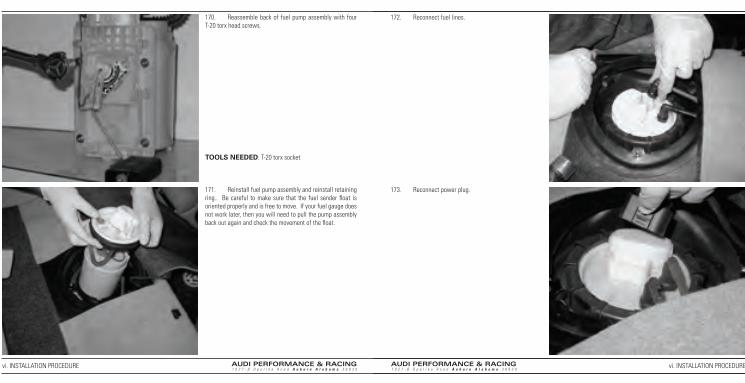
170. Reassemble back of fuel pump assembly with four T-20 torx head screws.
171. Reinstall fuel pump assembly and reinstall retaining ring.. Be careful to make sure that the fuel sender fl oat is oriented properly and is free to move. If your fuel gauge does not work later, then you will need to pull the pump assembly back out again and check the movement of the fl oat.
172. Reconnect fuel lines.
173. Reconnect power plug.
TOOLS NEEDED: T-20 torx socket
vi. INSTALLATION PROCEDURE vi. INSTALLATION PROCEDURE

AUDI PERFORMANCE & RACING1 0 2 7 - B O p e l i k a R o a d A u b u r n A l a b a m a 3 6 8 3 0
AUDI PERFORMANCE & RACING1 0 2 7 - B O p e l i k a R o a d A u b u r n A l a b a m a 3 6 8 3 0
174. Reinstall fuel pump cover.
175. Reinstall seat base and replace gas cap.
176. Reconnect negative battery terminal.
177. Refi ll oil and coolant. We suggest Mobil 1 5W-30. Amsoil, Redline, and Royal Purple are also OK. Nothing else is suggested. Any oils with Tefl on-TM or similar additives are not approved for use with this kit.
178. You should have received your ECU by now with the stage three software. Install the ECU in the reverse order of removal.
179. Check your work and make sure that all fasteners (nuts, bolts, clamps, etc.) are tight. Double check vacuum line routing against the diagrams in the instructions.
180. Check for any loose tools around vehicle. Before you start the engine turn the key to the on position and leave it there for three minutes. This will enable the throttle adaptation sequence. Once you have done this, start engine while the car is on the lift and check for any exhaust or fl uid leaks.
TOOLS NEEDED: Phillips head screwdriver TOOLS NEEDED: 10mm wrench
vi. INSTALLATION PROCEDURE vi. INSTALLATION PROCEDURE
181. Remove vehicle from lift and turn it off. Check for any leaks and top off any fl uids that may be low.
AUDI PERFORMANCE & RACING1 0 2 7 - B O p e l i k a R o a d A u b u r n A l a b a m a 3 6 8 3 0
AUDI PERFORMANCE & RACING1 0 2 7 - B O p e l i k a R o a d A u b u r n A l a b a m a 3 6 8 3 0
FIRST DRIVE
Now that you have topped off the fl uids, and checked for errant tools, it is time to take it for the fi rst drive. As you gently pull out to the street you will notice that it drives exactly like it did before. Do not be fooled, your car has been completely transformed. It deserves and requires your respect. The fi rst drive is as much about getting you familiar with your new car as it is a shakedown run for the install. To serve both of those purposes, it is very important that you take things slowly. It is best if you do not have an overly excited friend along with you. It is very dangerous to show off with a car that you are not familiar with. Make sure that you are wearing your seat belt, nothing is loose in the cabin that could slide around and hit you, and that you remembered your wallet. You should have a cell phone just in case you forgot to tighten that one hose and it blows off.Turn off ASR, it kicks in abruptly and can be mistaken for problems with the engine. Pull out onto the street when there is no traffi c to rush you. Use only light throttle inputs. Be very smooth and delicate with the throttle and during shifts. Roll into the throttle smoothly and let the engine wind out at low boost. Watch for strange noises. The turbo will sound completely different from what you are used to. It will take you some time to be able to distinguish the normal turbo noise from an intake leak noise. Either way, do not worry too much about air noises at this point. Just make sure that there are no rattles or components making contact in ways that they should not be.Now start looking at the temp gauges. The water temp should be up to normal by now. If you have an oil temp gauge, then it should be at 200°F. Now you can start to run a little more boost. That new hissing noise that you hear is your tires spinning. Be very careful about how much power you use in the lower gears. Do not add power in a turn, only when the car is pointed straight. If you get in trouble, let off the throttle completely, concentrate on steering the car fi rst, then brake. As you get more comfortable with your new car gradually increase the power. You need to be well away from any traffi c, bikers, joggers, etc. at this point. Do not break any traffi c laws or behave dangerously. Now you are overdue for going home. Your brakes are smoking, they faded out ten minutes ago. Your friends are worried that something happened. Drive home slowly. Let the car cool off. That guy in the Kia with the chrome wheels and Folgers exhaust isn’t worth the trouble. Welcome to the next level. You are now a Stage 3 owner.
TROUBLE SHOOTING CONTACT INFORMATION
If you have any questions that cannot be answered by readdressing the corresponding installation procedure please give us a call. You can reach us at 1.800.680.7921. We hope that you enjoy many miles of APR performance from your new Transverse Stage III turbo kit.
viii.TROUBLE SHOOTING CONTACT INFORMATIONvii. FIRST DRIVE