transportation engineering - seismic consolidation
TRANSCRIPT

Transportation Engineering
Contact Hours -3+3
Dr Hassan Mujtaba
Course Code –CE-422

Turnout
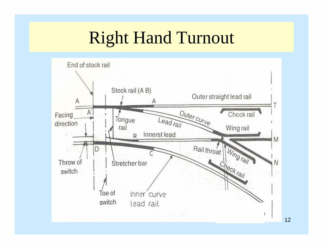
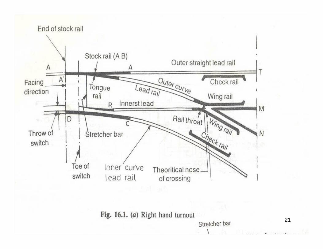
• Combination of points and crossings by manipulationof which a train may be transferred from one track toanother track is called a turnout.
• A turnout may be let hand turnout or right handturnout.
2
Components of a Turnout
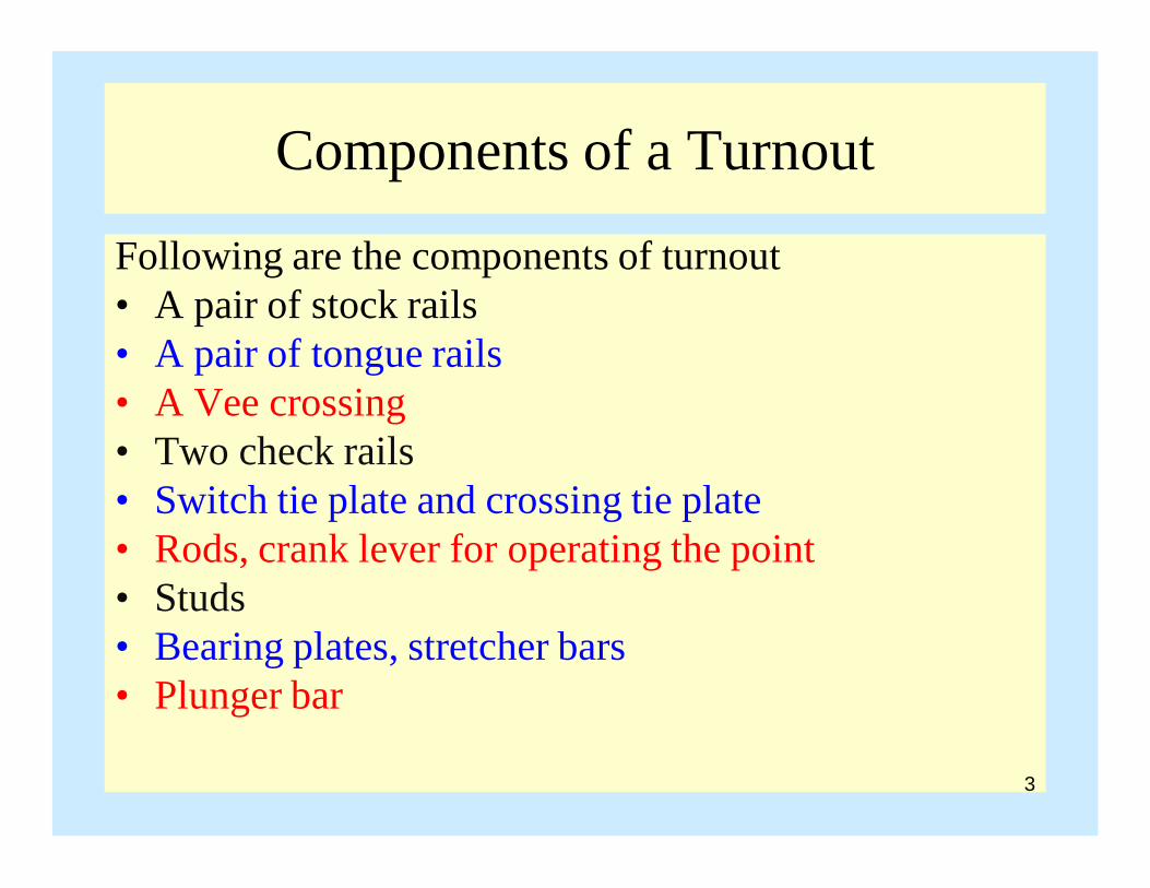
Following are the components of turnout• A pair of stock rails• A pair of tongue rails• A Vee crossing• Two check rails• Switch tie plate and crossing tie plate• Rods, crank lever for operating the point• Studs • Bearing plates, stretcher bars• Plunger bar
3

Right Hand Turnout
4
Point
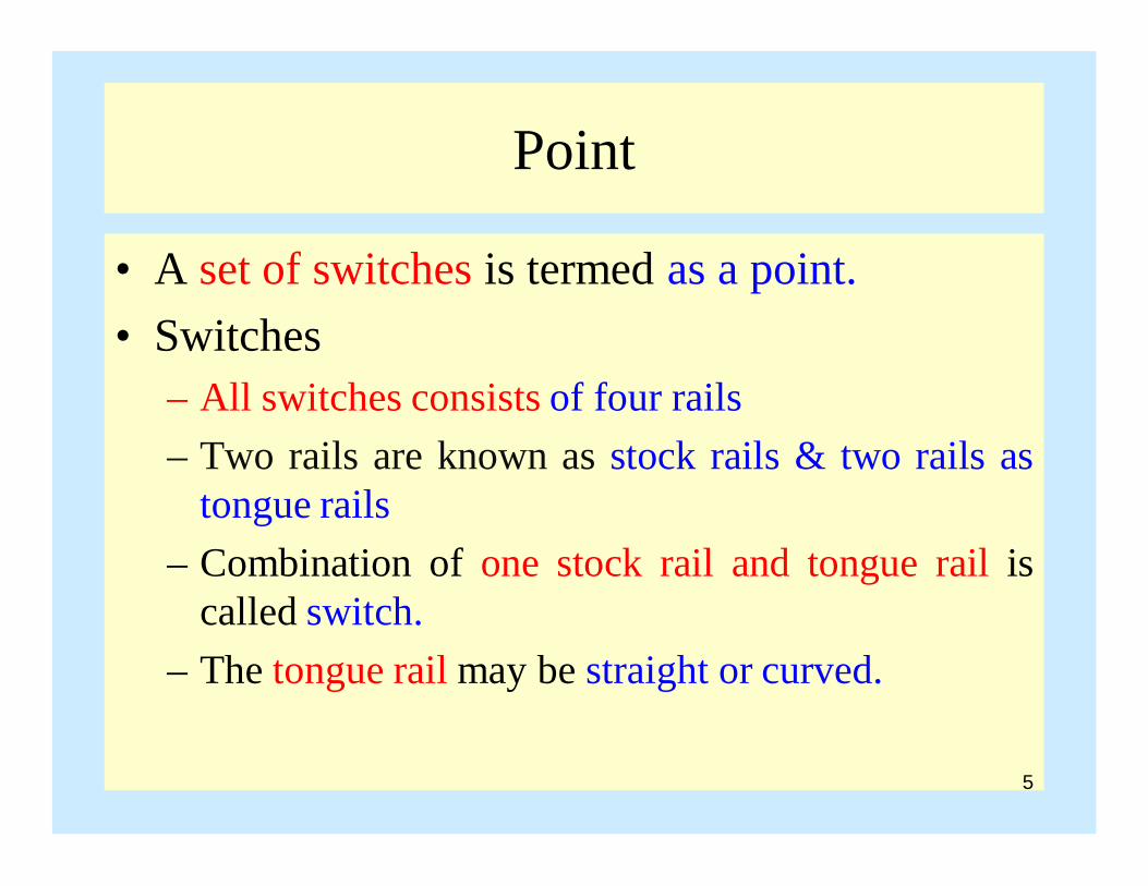
• A set of switches is termed as a point.• Switches
– All switches consists of four rails– Two rails are known as stock rails & two rails as
tongue rails– Combination of one stock rail and tongue rail is
called switch.– The tongue rail may be straight or curved.
5

Toe of Switch
Heel of Switch
Tongue Rail
Stock Rail
Point
6
Stock Rail
Point
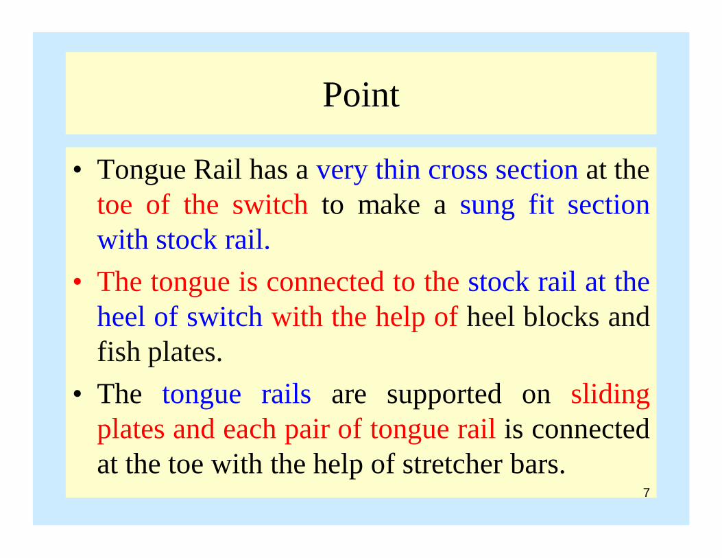
• Tongue Rail has a very thin cross section at thetoe of the switch to make a sung fit sectionwith stock rail.
• The tongue is connected to the stock rail at theheel of switch with the help of heel blocks andfish plates.
• The tongue rails are supported on slidingplates and each pair of tongue rail is connectedat the toe with the help of stretcher bars.
7
8
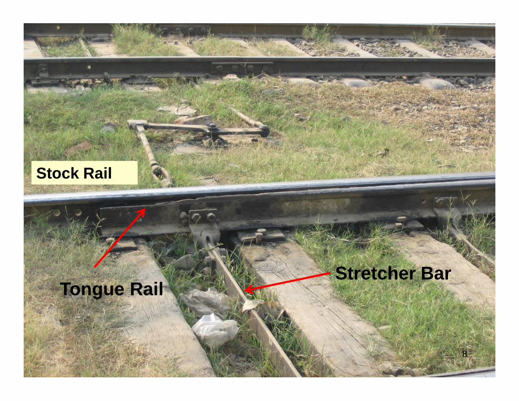
Stock Rail
Tongue RailStretcher Bar

Point
• Tongue rails are laid at slightly lower elevationthan the stock rail to avoid wear.
• Facing Point- if the train travels from the toe toheel of the switch, the point is known as facingpoint.
• Trailing Point- if the train passes over the heelfirst and afterwards toe it is called trailingpoint.
9

Point
• The same set of points can act as facing aswell as trailing points.
• When the train passes over the point first andafterwards the crossing, the turnout is calledfacing turnout.
• If the train passes the crossing first andafterwards the point then it is called trailingturnout.
• If we stand facing the point, the switch to theright is the right hand switch and to the left isthe left hand switch.
10

Point
• Throw of Switch- the distance by which the toe ofthe tongue is moved from its contact position
• Heel Divergence- distance between the stock railand the tongue rail at the heel of switch is calledheel divergence.
• Switch Angle- angle subtended between thegauge faces of the stock rail and tongue rail. Itsvalue depends upon heel divergence and length ofthe tongue rail. The smaller the switch angle, thesmoother is the running over the turnout.
11
Right Hand Turnout
12

13
Right Hand Turnout

Switch Angle and Heel Divergence
14
Throw of SwitchThe distance by which the toe of the tongue is moved from its contact position.
Heel Divergence- distance between the stock rail and the tongue rail at the heel of switch is called heel divergence.

Point• Flange Way Clearance - is
provided as clearance forthe movement of wheelflanges and for this reasonit is known as flange wayclearance.
• Flange Way Depth - is thevertical distance betweenthe top of the heel blockand top of the head of stockrail.
15
Heel Divergence- distance between the stock rail and the tongue rail at the heel of switch is called heel divergence.

Crossing
• The function of crossing is to enable the flanges ofwheels to cross the rails.
• Components of crossing are VEE piece and wing rails• Vee piece consists of point rail and splice rail
16
Crossing
• Point rail and Splice Rails are connected together.• Point rail ending at nose and splice rail little behind
the nose.• Actual nose is a bit less than theoretical nose.• Theoretical nose is the point where the gauge face of
point and splice rails cross and is a little ahead ofactual nose other wise nose would be too slender ifbrought to a fine point.
17

18
Crossing
• The nose is kept ¾ in in particular.• Toe of crossing• Heel of Crossing• Angle of Crossing- angle between the gauge faces of
point rail and splice rail.• Gauges faces are the faces with which wheel flanges
comes in contact.• The size of the crossing is measured by its angle
19

Crossing
• Throat is the narrowest space between the twowing rails where they are bent.
• Check rails are provided for guiding the flangeof the wheel when the opposite wheel isnegotiating the gap at the crossing.
• Wing rails guide the flange of the wheel whenit moves over the throat.
• The rails which connect point with thecrossing are called lead rails.
20
21

Check Rail
Wing Rails
CROSSING
22
Point Rail
Throat
SpliceRail

Left Hand Turnout
23
Left Hand and Right Hand Turnout
• Combination of points and crossings bymanipulation of which a train may betransferred from one track to another track iscalled a turnout.
• A turnout may be let hand turnout or righthand turnout.
• The distance from the toe of the switch to theheel of crossing is called overall length ofturnout
24

25
Length of Turnout

Point and Crossings
26
• Point– Two Switches
• Switch– Stock Rail (more in
x-section)– Tongue Rail
• Crossing– Wing Rails– Vee Piece
• Vee Piece– Point Rail (more in
length than Splice Rail)
– Splice Rail

Toe of Switch
Heel of Switch
Tongue Rail
Stock Rail
27
Stock Rail
Facing Point- if the train travels from the toe to heel of the switch, the point is known as facing point.
Toe of Switch
Heel of Switch
Tongue Rail
Stock Rail
28
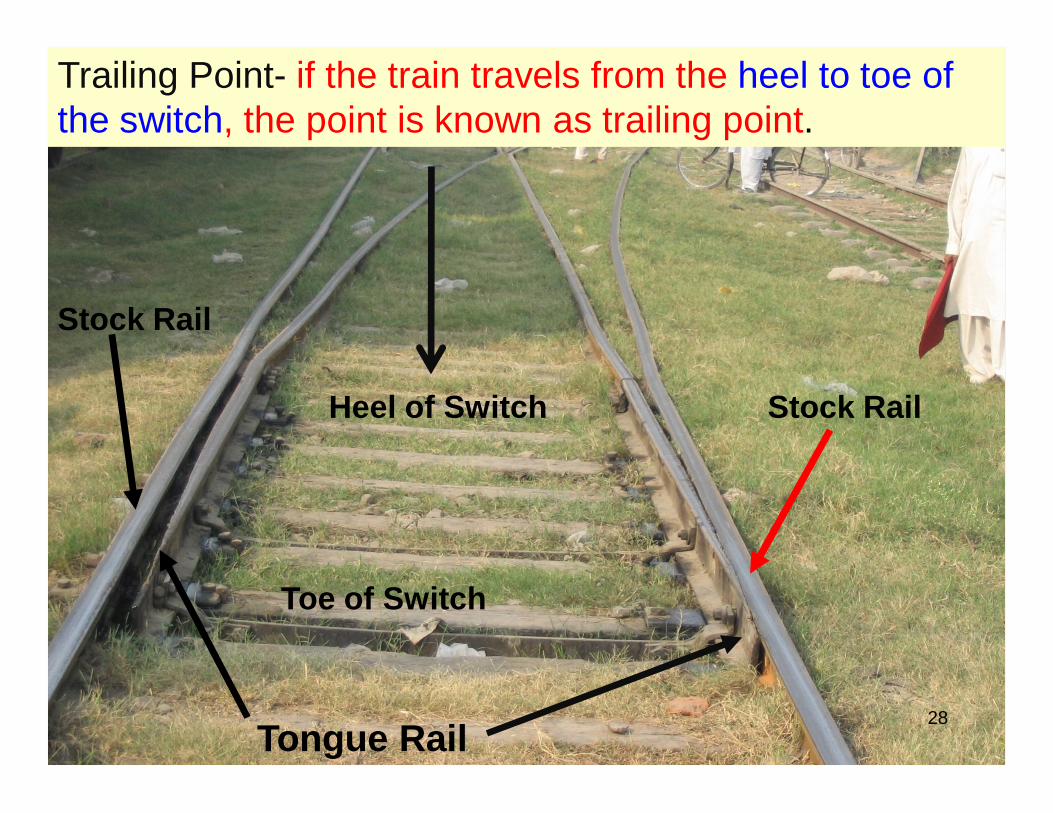
Stock Rail
Trailing Point- if the train travels from the heel to toe of the switch, the point is known as trailing point.

Actual and Theoretical Nose of Crossing

Size of Crossing• Size of a crossing is expressed in terms of distance
required in spreading point and splice rail by onefoot.
• The spread is measured between gauge faces of therails.
• If the spread between the point rail and splice rail at adistance of x ft from the nose of crossing is 1 ft, thesize of crossing is 1 in x.
• Generally size is 1:8.5, 1:12 & 1:16.• Crossing with sharp angles are used over the track
where high speed prevails.30

Size of Crossing• Size of a crossing is expressed in terms of distance
required in spreading point and splice rail by onefoot.
• The spread is measured between gauge faces of therails.
• If the spread between the point rail and splice rail at adistance of x ft from the nose of crossing is 1 ft, thesize of crossing is 1 in x.
• Generally size is 1:8.5, 1:12 & 1:16.• Crossing with sharp angles are used over the track
where high speed prevails.31

Size and Angle of Crossing• As a rough rule, permissible speed in miles per hour
is kept less than twice the number of crossing• Speed over 1 : 10 crossing should be kept below 20
mph.• The angle between gauge faces of point rail and
splice rail is angle of crossing.There are three method to set crossing angle• Right angle method (Cole’s Method)• Centerline method• Isosceles Method
32

Size and Angle of Crossing• Find out the values of crossing angles for 1 : 12 and
1: 8.5 by three methods.
33

Switch• Switch is the combination of stock rail and tongue
rail.• The distance between stock rail and tongue rail at the
heel of switch is heel divergence.• Heel divergence value depends upon flange clearance
and width of rail head.• The value of switch angle depends on heel divergence
and length of tongue.• For BG heel divergence varies from 51/4” to 5 3/8”
34

Toe of Switch
Heel of Switch
Tongue Rail
Stock Rail
Turnout
35
Stock Rail

Length of Switch
36
• Crossing Size– 1 :16
– 1:12
– 1 in 8.5
• Length of Switch– 32 ft
– 21 ft
– 15.5 ft

Types of Switch
• Stub Switch (obsolete)– It is old design– They do not have separate tongue rails
rather than stock rails move inward• Split Switch
– Loose heel type– Fixed Heel Type
37

Switch• Loose Heel Type
– In this type, the rail pivots about the heel joints held byblocks and fish plates.
– The tongue rail finishes at the heel of the switch– The fish plates holding the switch rail is slightly bent.– The disadvantage of this type of switch is that due to abrupt
change of curvature, the rolling stock get a knocking.
38

Switch
• Fixed Heel type– The tongue rail does not end at the heel of switch
rather it is extended beyond it.– The movement at the toe of switch is made
possible by the flexibility of the tongue rail.
39
Types of Switch Based on Shape
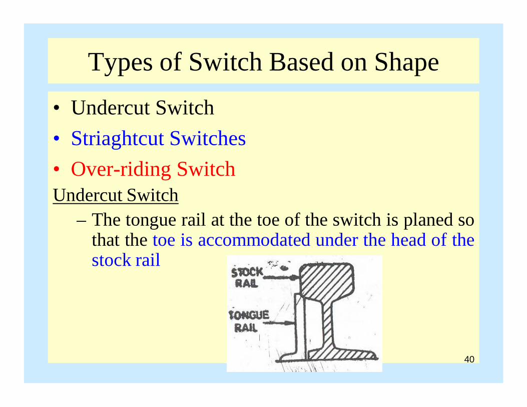
• Undercut Switch• Striaghtcut Switches• Over-riding SwitchUndercut Switch
– The tongue rail at the toe of the switch is planed sothat the toe is accommodated under the head of thestock rail
40

Types of Switch Based on ShapeUndercut Switch
– In modified section, half web of the to tongue railis below the head of the stock rail and the width oftop of tongue rail is increased. This modificationreduces the splitting tendency of tongue.
41

Types of Switch Based on Shape• Straight Cut Switch
– The tongue rail is kept slightly in line with the stockrail. This is usually provided for Bull headed rails
• Overriding Switch– The tongue rail slides over the foot of the stock rail.
42
Tongue Rail
Stock Rail

Types of Turnout
• Double Turnout• Diamond Crossing• Symmetrical split• Crossover• Gathering Lines• Gauntlet Track• Temporary Diversion
43

Double Turnout• This is also known as tandem turnout. Two turnout
takes off from the main track.
44
Diamond CrossingWhen two track of same gaugeor different gauge cross eachother at an angle less than 90deg. Two angles are acute andtwo angles are obtuse

Double Turnout• This is also known as tandem turnout. Two turnout
takes off from the main track.
45
Diamond CrossingWhen two track of samegauge or different gaugecross each other at anangle less than 90 deg.Two angles are acute andtwo angles are obtuse

Symmetrical Split• This is also known as equivalent turnout. If two
similar turnouts are taken out from the straight trackin two different directions such a junction is knownas symmetrical split.
46
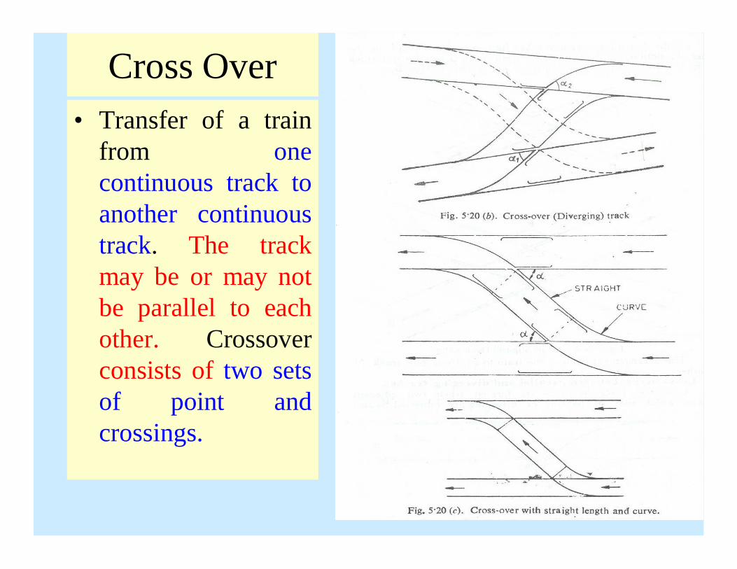
Cross Over• Transfer of a train
from onecontinuous track toanother continuoustrack. The trackmay be or may notbe parallel to eachother. Crossoverconsists of two setsof point andcrossings.
47

Scissors Cross-over• This is also known as double cross-over. This track
junction enables trains from opposite direction tochange the track. If the space is insufficient, scissorscross-over is provided.
48

Gathering Lines• When a number of parallel lines are connected
together with the main track, the connecting line iscalled gathering lines (ladder lines).
49
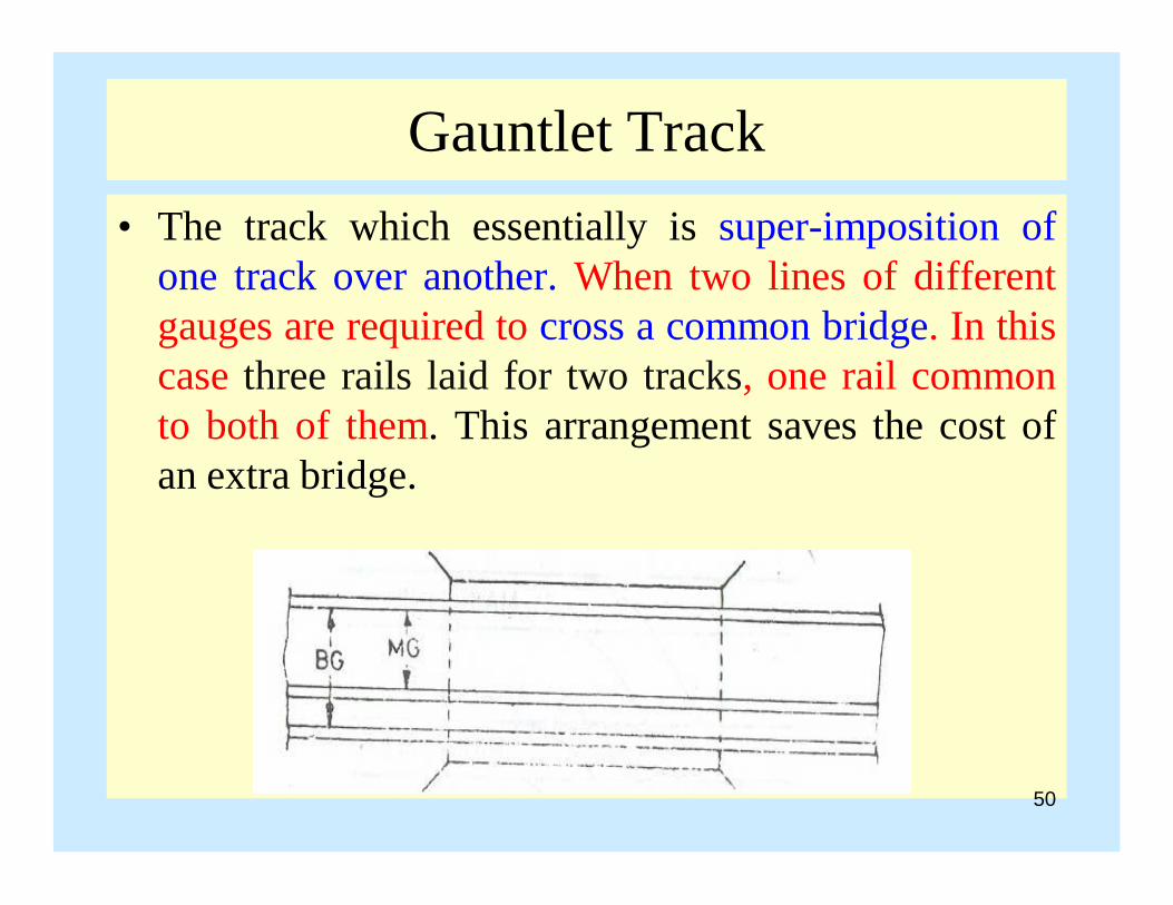
Gauntlet Track• The track which essentially is super-imposition of
one track over another. When two lines of differentgauges are required to cross a common bridge. In thiscase three rails laid for two tracks, one rail commonto both of them. This arrangement saves the cost ofan extra bridge.
50

Temporary Diversion• Whenever certain stretch of the track has to be closed
for one reason or the other, the traffic is diverted byproviding a temporary diversion.
51

Station and YardsStation means any place on a railway line, where
– Traffic is dealt.– Authority to proceed is given to trains.– Movement of the train is controlled to avoid accidents.
Requirement of Railway StationThe general features for a railway station can be
classified into following categories• General• Public• Traffic• Locomotive 52

Requirement for Railway StationGeneral• Suitable approach roads to station, offices for the staffPublic• Waiting room, Mosque, booking office, plate form,
Sanitory arrangement, Water supply, Restaurants,Telephone, parking
Traffic• Signals, sidings / side loopsLocomotives• Watering, fueling, inspection and repair, arrangement to
change the direction of locomotive53
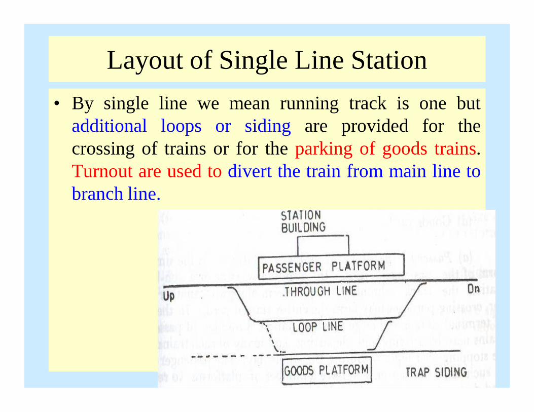
Layout of Single Line Station• By single line we mean running track is one but
additional loops or siding are provided for thecrossing of trains or for the parking of goods trains.Turnout are used to divert the train from main line tobranch line.
54

Layout of Double Line Station• Double line station is one in which two running
tracks are there. Crossovers are provided between thetwo main tracks. Advantage of double line station thatif the two trains are running in the same direction,then we have the facility, that the fast moving traincan pass the slow moving train without anydisturbance.
55

Layout of Double Line Station
56

Junction• Junction is a station where a branch line track meets
with the main line track or any other combination.Special arrangement are made for interchange oftraffic between branch line and main line.
• Terminal is a station at which a railway line or one of its branches terminates or ends.
Dead End / Buffer Stop• It is provided where the track ends. Buffer is a spring
loaded device which absorbs the shock in case thetrain touches it.
57

Terminal
58

Buffer Stop
59

Platform• Passenger Platform• Goods PlatformPassenger Platform• Minimum width = 12 ft (The width varies but min is
12 ft beyond which buildings are constructed)• Length= The length should not be less than longest
passenger train• In Pakistan, length is 600 – 1000 ft.• Minimum height above the rail level is 2.5’ to 2.75’.
60

Good Platform• Height of the good platform is more than the height
of the passenger platform.• Normally, the top of the good platform must be flush
with the floor level of the good wagon so that bulkyarticles can easily be loaded in the wagons.
61

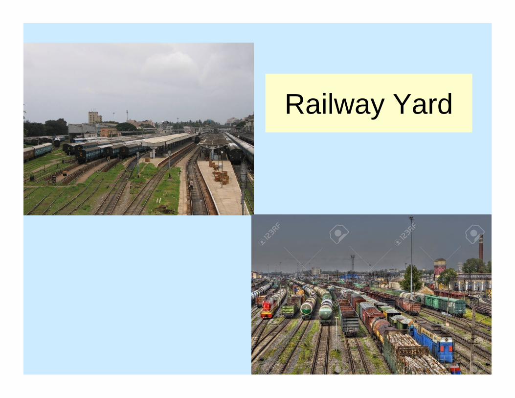
Yards• Yard is the network of tracks laid within definite
limits for sorting of vehicles and making up of trains.• Yards are usually laid on level ground as gradient in
case of yards is not desirable. Normally 1 : 1000 isrecommended and in difficult situation 1 in 400.
• Layout of the yard depends upon passenger traffic,goods traffic and the type of traffic.
Railway Yard can be divided into• Passenger Yards • Goods Yard• Marshalling yard • Loco yard 62
Railway Yard
63

Passenger Yards• The function of the passenger yard is to provide
facility for the movement of passengers and vehiclesfor passengers.
Goods Yards• A goods yard has to cater for the receipt, loading,
unloading and delivery of goods and movement ofgoods vehicles.
• This portion includes facility for goods traffic, looplines, goods shed and machinery for loading andunloading of bulky vehicles.
64

Locomotive Yards• It is the space where facilities have to be provided for
service and inspection of locomotives.• The loco yard contains a number of tracks leading
engine to shed, inspection pits, repair pits, turntable,repair shed, water columns for filling water etc.
65

Marshalling Yards• Marshalling yards are used for the sorting of the
goods vehicles and to arrange the wagons, in order oftheir destination. Marshalling yards are thedistributing centers.
• Empty wagons are also kept in marshalling yard anddispatched to different stations as and when required.
66
Design Requirement of Marshalling Yards
• Marshalling yards should be designed in such a mannerthat shunting operation does not disturb the schedule ofthe regular trains.
• It should be located parallel to the main line.• Marshalling yard should be designed in such a way that
maximum number of wagons, are dispatched to theirdestination in short time.
• Movement of vehicle should be preferably in onedirection so that process will be easier and conflicts arethe minimum.
• Necessary repair facilities should be provided inmarshalling yard.
67
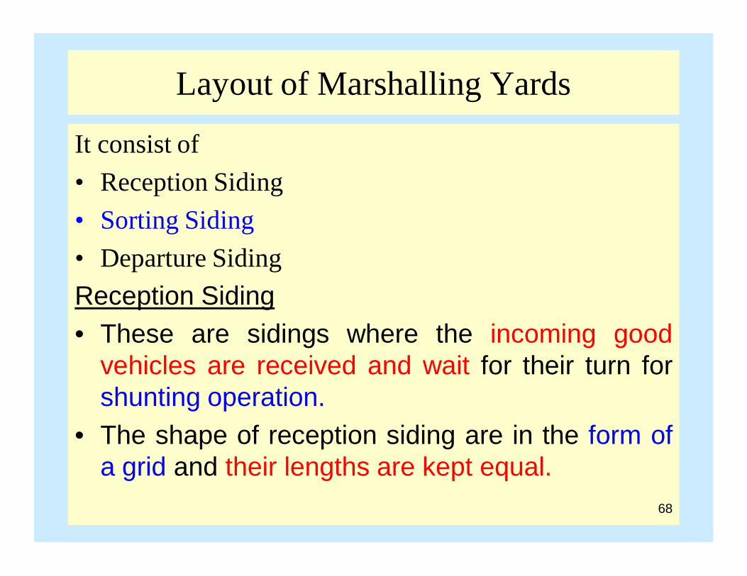
Layout of Marshalling Yards
It consist of• Reception Siding• Sorting Siding• Departure SidingReception Siding• These are sidings where the incoming good
vehicles are received and wait for their turn forshunting operation.
• The shape of reception siding are in the form ofa grid and their lengths are kept equal.
68
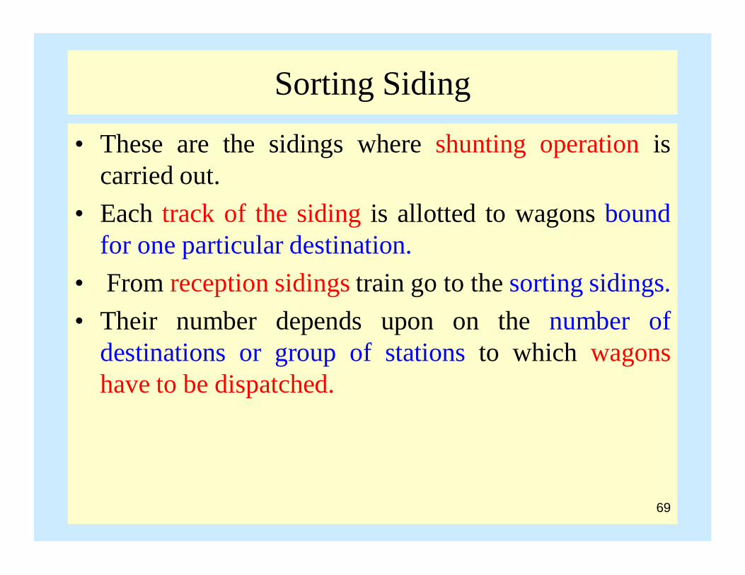
Sorting Siding
• These are the sidings where shunting operation iscarried out.
• Each track of the siding is allotted to wagons boundfor one particular destination.
• From reception sidings train go to the sorting sidings.• Their number depends upon on the number of
destinations or group of stations to which wagonshave to be dispatched.
69

Departure Siding
• Departure sidings are optional, these would dependupon the intensity on the main track.
• If the main track is busy then we have departuresiding. It is also in the form of grids as the receptionsiding
70
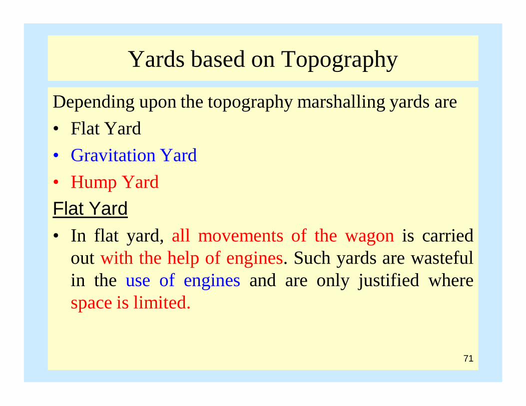
Yards based on Topography
Depending upon the topography marshalling yards are • Flat Yard• Gravitation Yard• Hump YardFlat Yard• In flat yard, all movements of the wagon is carried
out with the help of engines. Such yards are wastefulin the use of engines and are only justified wherespace is limited.
71
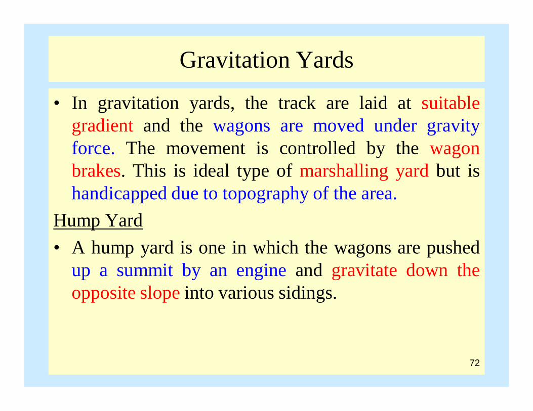
Gravitation Yards
• In gravitation yards, the track are laid at suitablegradient and the wagons are moved under gravityforce. The movement is controlled by the wagonbrakes. This is ideal type of marshalling yard but ishandicapped due to topography of the area.
Hump Yard • A hump yard is one in which the wagons are pushed
up a summit by an engine and gravitate down theopposite slope into various sidings.
72
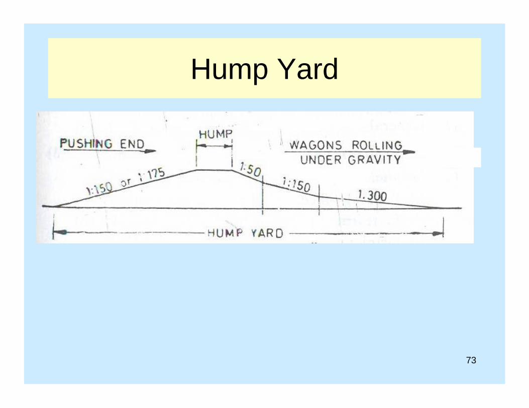
Hump Yard
73

Site selection for railway Station
• The proposed site should be on a fairly level groundwith good drainage facilities.
• It should be near town or city.• Sufficient area for future development• It should be able to serve the needs for civil and
military authorities.• The site should be such that permissible gradient
should be easily attained.
74

Construction of Permanent Way
• Land Acquisition (temporary and permanent)• Earthwork (formation, ballast, sleepers, rails)• Construction of Bridges• Construction of Station Building and Staff
Quarters• Plate Laying• Ballast Laying
75
Plate Laying
• The operation of laying out rails and sleepers over thecompacted formation is known as plate laying.
• The packing of ballast is not covered under platelaying since the formation is allowed to consolidateunder the traffic carried out by the railway line.
• In plate laying the point up to which the track hasalready been laid is known as rail head.
• The point from which laying of track is to start isknown as base.
76
Methods for Track Construction
• Side Method/ Tramline Method• Telescopic Method• American MethodTramline Method• This method is used when a track already exist such
as doubling of track.• The material required for track construction are
carried to the site in material trains.• The assembly of the track component is started from
one end by the manual labor.
77

Tramline Method
• This method can be employed for laying ofnew track.
• In this case construction material is carried outon trucks or temporary track
• The temporary track is placed at a lower levelas compared to main track.
• The work of linking of track can be started atmore than one point.
78
Telescopic Method• This method can be employed for laying of new track.• In this case construction material is carried out on trucks
or temporary track. The temporary track is placed at alower level as compared to main track.
• The work of linking of track can be started at more thanone point.
• In this method rails, sleepers and fittings are unloadedfrom the material train as close to the rail head aspossible.
• The sleepers are carried either by carts or by the menalong the adjoining service roads and spread on theballast.
• Rails are carried by rail carrier or by men.79
Telescopic Method
• Labour working on the laying of track may bedivided into three groups– Material Gang– Linking- in- gang– Packing-in-gang
Material Gang– Their responsibility is to unload the material from
the train and To arrange the material item wise– To transport it to site.– The transportation of the rail is a specialized job
and this party is specially trained for this job.80

Telescopic Method
• Linking- in- gang– their responsibility is to fix the rails to the sleepers
and link the rail together to the fish plates.• Following sequence is adopted for linking
– Marking the centre line of track– Laying of sleepers– Placing of bearing plate above the sleepers– Fixing of rails to sleepers– Provision of expansion joints– Joining by fish plate
81

Telescopic Method
• Packing-in-gang– The function of this gang is to pack the earth
below and round the sleepers and bring the track tolevel
– To bring the track to correct alignment and level.American Method• This is a mechanical method. In this method special
track laying machines are used.• Preassembled panels of track, each panel consisting
of rails with appropriate number of sleepers are takento the rail head with machinery and is linked.
82

83

84

Material Depot
• In any method of linking the progress depends uponvery much on correct and regular supply of materialat the rail head.
• To ensure this supply, one or more material depotsare established.
• The main depot is usually laid out at a convenient sitenear the point of junction of the new track with anexisting railway.
• Materials required for the construction of newrailway line are received from the material train at themain depot and are arranged at the main depot.
85

Material Depot
• The layout should be such that the wagons can beunloaded and removed quickly. Mechanical devicese.g cranes for unloading heavy material may also beemployed.
• Minimum two sets of wagons are necessary. If onewagon is at the rail head, the other is loaded at thedepot. If the distance between the rail head and depotis large, subsidiary depot near the rail head may beestablished.
• The stock of the material is so arranged that thecorrect number of each item is available for loadingwithout any loss of time.
• The material train should be marshalled in correctorder.
86

87

88

89

90