transportation and installation requirements - medium...
TRANSCRIPT
Transportation and Installation RequirementsMEDIUM VOLTAGE STATION 600 / 1200 / 1800for SUNNY TRIPOWER 60
MVS-STP-10-TA-en-11 | Version 1.1ENGLISH

Table of Contents1 Information on this Document..................................................................................................... 3
1.1 Validity ............................................................................................................................................................. 31.2 Additional Information..................................................................................................................................... 31.3 Nomenclature .................................................................................................................................................. 3
2 Product Overview ........................................................................................................................ 42.1 System Overview............................................................................................................................................. 42.2 Design of the MV Station ................................................................................................................................ 52.3 Option code..................................................................................................................................................... 62.4 Scope of Delivery ............................................................................................................................................ 82.5 External dimensions and weights ................................................................................................................... 9
3 Transport and Mounting.............................................................................................................. 103.1 Transport by truck or ship................................................................................................................................ 103.2 Storage............................................................................................................................................................. 113.3 Requirements for Transport Routes and Means of Transport........................................................................ 113.4 Unloading ........................................................................................................................................................ 11
4 Information for Installation ......................................................................................................... 154.1 Minimum Clearances ...................................................................................................................................... 154.2 Ambient Conditions ......................................................................................................................................... 154.3 Installation ........................................................................................................................................................ 16
4.3.1 Design of the PV System with MV Station ...................................................................................................... 164.3.2 Support surface ................................................................................................................................................ 164.3.3 Pea gravel ground ........................................................................................................................................... 174.3.4 Weight load ..................................................................................................................................................... 184.3.5 Mounting options ............................................................................................................................................. 18
4.3.5.1 Pile-driven steel pillars..................................................................................................................................... 184.3.5.2 Concrete pillar................................................................................................................................................. 18
4.3.6 Installation of the Temporary Service Platform............................................................................................... 194.3.7 Recesses in the Support Surface ..................................................................................................................... 20
4.4 Oil Containment .............................................................................................................................................. 21
5 Electrical Connection .................................................................................................................... 235.1 Grounding Concept ........................................................................................................................................ 235.2 Cable Entry ...................................................................................................................................................... 235.3 Cable Requirements ........................................................................................................................................ 24
6 On-Site Services............................................................................................................................ 25
Table of Contents SMA Solar Technology AG
Transportation and Installation RequirementsMVS-STP-10-TA-en-112

1 Information on this Document
1.1 ValidityThis document is valid for the following device types:
Device type Production version
MV Station 600 for Sunny Tripower 60(MVS-600-STP-10)MV Station 1200 for Sunny Tripower 60(MVS-1200-STP-10)MV Station 1800 for Sunny Tripower 60(MVS-1800-STP-10)
1.0
The production version of the MV Station is indicated on the type label.Illustrations in this document are reduced to the essential and may deviate from the real product.
1.2 Additional InformationLinks to additional information can be found at www.SMA-Solar.com.
1.3 NomenclatureComplete designation Designation in this document
Sunny Tripower 60STP 60-10
Sunny Tripower or inverter
MV Station for Sunny TripowerMVS-600-STP-10MVS-1200-STP-10MVS-1800-STP-10
MV Station
Medium-voltage switchgear MV switchgear
Medium-voltage transformer MV transformer
1 Information on this DocumentSMA Solar Technology AG
Transportation and Installation Requirements 3MVS-STP-10-TA-en-11

2 Product Overview
2.1 System OverviewThe MV Station, together with a PV array and a number of Sunny Tripower inverters, forms a PV power plant.All devices necessary for feeding the alternating current coming from the inverters into the medium-voltage grid areinstalled in the MV Station. The MV Station is based on a modular concept in which you can select the componentsaccording to the specific project requirements. Up to 30 Sunny Tripower inverters can be connected to the MV Station.Several MV Stations can be connected together to form a ring or string on the medium-voltage side.
INVERTER-MANAGER
MEDIUM VOLTAGE STATION
SUNNY TRIPOWER 60
SUNNY TRIPOWER 60
MEDIUM VOLTAGE STATION
SUNNY TRIPOWER 60
SUNNY TRIPOWER 60
I/O BOX
ROUTERWEATHERSTATION
UTILITY GRID
UTILITY GRID
ACETHERNETRS485
Figure 1: Design of the PV power plant with MV Stations (example)
The Inverter Manager and the I/O Box can be installed in the MV Station as an option and can control the output ofthe inverters. Up to 42 inverters can be connected to one Inverter Manager. This means that PV systems can bedesigned with several MV stations, whereby not every MV station has to be fitted with an Inverter Manager.
2 Product Overview SMA Solar Technology AG
Transportation and Installation RequirementsMVS-STP-10-TA-en-114

2.2 Design of the MV Station
A
B
D
C
Figure 2: Design of the MV Station
Position Designation Explanation
A Low-voltage compart-ment
The AC low-voltage cables from the inverters are connected in the low-voltagecompartment.
B MV transformer The MV transformer converts the inverter output voltage to the voltage level ofthe medium-voltage grid.
C Medium-voltage com-partment
MV switchgear*The MV switchgear connects and disconnects the MV transformer to and fromthe medium-voltage grid.
Station subdistributionThe station subdistribution contains fuse elements for the supply of the stationand the optional Inverter Manager.
Inverter Manager*The Inverter Manager is a device for monitoring and controlling up to 42Sunny Tripower inverters. The Inverter Manager receives the specificationsfrom the optional I/O Box and controls all inverters in the system accordingly.Further information on the Inverter Manager is to be found in the documenta-tion supplied with the Inverter Manager.
I/O Box*The I/O Box is a multi-function interface for one Inverter Manager. The I/O Box receives commands for grid management services via digital signalsand sends these specifications to the Inverter Manager.Further information on the I/O Box is to be found in the documentation sup-plied with the Inverter Manager.
D Service platform The elevated position of the service platform makes operating the devices inthe medium-voltage compartment easier. The service platform is only foldedout when operations are to be performed on the medium-voltage compart-ment.
* optional
2 Product OverviewSMA Solar Technology AG
Transportation and Installation Requirements 5MVS-STP-10-TA-en-11

2.3 Option codeThe MV Station is available in various power classes:
MV Station Inverter
MVS 600 STP a maximum of 10 inverters
MVS 1200 STP a maximum of 20 inverters
MVS 1800 STP a maximum of 30 inverters
You can use the option code to select an MV Station configuration which is tailored specifically to your project.However, not all order options can be combined with each other. Consult your SMA contact person if you have anyquestions.
Order option 1 2 3 4 5 6 7 8 9 Description
MV transformer 0 Mineral oil, with full hermetic pro-tection
1 Organic oil with increased flashpoint above 300°C, with full her-metic protection
Nominal voltage 1 10.0 kV
2 11.0 kV
3 12.0 kV
4 12.5 kV
5 13.2 kV
6 13.8 kV
7 15.0 kV
8 20.0 kV
9 22.0 kV
A 23.0 kV
B 30.0 kV
C 33.0 kV
D 34.5 kV
Nominal frequency 0 50 Hz
1 60 Hz
Transformer vector group 0 Dyn11
1 YNyn0
Oil spill tray 0 Without
1 With (separate component)
2 Product Overview SMA Solar Technology AG
Transportation and Installation RequirementsMVS-STP-10-TA-en-116
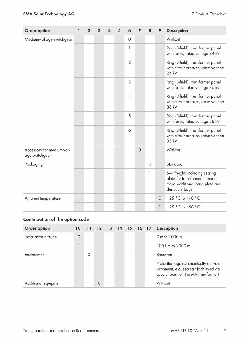
Order option 1 2 3 4 5 6 7 8 9 Description
Medium-voltage switchgear 0 Without
1 Ring (3-field), transformer panelwith fuses, rated voltage 24 kV
2 Ring (3-field), transformer panelwith circuit breaker, rated voltage24 kV
3 Ring (3-field), transformer panelwith fuses, rated voltage 36 kV
4 Ring (3-field), transformer panelwith circuit breaker, rated voltage36 kV
5 Ring (3-field), transformer panelwith fuses, rated voltage 38 kV
6 Ring (3-field), transformer panelwith circuit breaker, rated voltage38 kV
Accessory for medium-volt-age switchgear
0 Without
Packaging 0 Standard
1 Sea freight, including sealingplate for transformer compart-ment, additional base plate anddesiccant bags
Ambient temperature 0 −25 °C to +40 °C
1 −25 °C to +50 °C
Continuation of the option code
Order option 10 11 12 13 14 15 16 17 Description
Installation altitude 0 0 m to 1000 m
1 1001 m to 2000 m
Environment 0 Standard
1 Protection against chemically active en-vironment, e.g. sea salt (achieved viaspecial paint on the MV transformer)
Additional equipment 0 Without
2 Product OverviewSMA Solar Technology AG
Transportation and Installation Requirements 7MVS-STP-10-TA-en-11

Order option 10 11 12 13 14 15 16 17 Description
Inverter Manager 0 Without
1 With Inverter Manager and power sup-ply unit
2 With Inverter Manager, power supplyunit and I/O Box
LV circuit breaker 0 Without
1 With circuit breaker between MV trans-former and low-voltage distribution, in-cluding 2 active fans
LV energy meter 0 Without
Country package 0 Without
Language DE German
EN English
FR French
ES Spanish
2.4 Scope of DeliveryCheck the scope of delivery for completeness and any externally visible damage. Contact your distributor if the scopeof delivery is incomplete or damaged.
F
CA
G
B
E
D
Figure 3: MV Station Scope of Delivery
Position Quantity Designation
A 1 MV Station
B 4 Support feet for the container
C 8 Base plates for the support feet for compensation of unevenness (fourunits available in two thicknesses: 2 mm and 5 mm)
D 1 Oil spill tray with oil drain valve*
2 Product Overview SMA Solar Technology AG
Transportation and Installation RequirementsMVS-STP-10-TA-en-118

Position Quantity Designation
E 1 LV/HRC fuse extractor with sleeve
F 1 Spare paint
G 1 Documentation: system manual, circuit diagram, MV transformer testprotocol, delivery test protocol, MV switchgear documentation, MVStation test protocol
* optional
2.5 External dimensions and weights
29
45
mm
2991 mm 2438 mm
Figure 4: Dimensions of the MV Station
Dimensions of the MV Station without platform or support feet
Width Height Depth Weight
MV Station 600 / 1200 / 1800 2991 mm 2591 mm 2438 mm < 9 t
Dimensions of the MV Station with platform and support feet
Width Height Depth Weight
MV Station 600 / 1200 / 1800 4013 mm 2945 mm 2438 mm < 9 t
The weight of the MV Station may vary below the indicated weight depending on the selected nominal voltage andpower class.
2 Product OverviewSMA Solar Technology AG
Transportation and Installation Requirements 9MVS-STP-10-TA-en-11

3 Transport and Mounting
3.1 Transport by truck or shipThe dimensions and shape of the MV Station correspond to those of an ISO container. This means that it can beloaded, secured for transport, transported and installed quickly and easily. It can be transported via truck or ship. Atruck 16 m long, 2.7 m wide, 5 m high, and with a total weight of 50 t can transport up to four MV Stations. Fortransport, two MV stations each can be coupled together using special coupling elements.All transport vehicles must be suitable for transporting containers.Transport via airfreight or railroad is not permitted.During transport and unloading, damage to the paint of the station container may occur. Damage to the paint doesnot impair the function of the MV Station. However, any damage must be remedied using the spare paint suppliedwithin three weeks at the latest.For transportation by truck or ship, the MV Station must be secured at least at all four lower corner castings. This canbe done by various methods, depending on the fastening system of the means of transportation. The most commonmethods are described below.
Twistlock• The MV Station is set down on the locking mechanisms. By
turning the twistlock, an interlocking is made.
Pinlock• The MV Station is set down on the locking mechanisms. Any
slippage of the load is prevented by inserting the pinlock.
3 Transport and Mounting SMA Solar Technology AG
Transportation and Installation RequirementsMVS-STP-10-TA-en-1110

For sea transport, two MV Stations can be coupled together using the quick-tie system. The respective sides in whichthe low-voltage compartments are situated are to be connected together.
≥45°
Figure 5: Coupling of 2 MV Stations for sea transport
Individual MV Stations can be loaded onto a 20°foot flat rack for sea transport. Three MV Stations can be loadedonto a 40°foot flat rack for sea transport.Oil trays and inverters are transported in a separate container or as general cargo.The exact transport conditions will be defined specifically for each project.
3.2 StorageFor storage of the MV Station, note the following points:
• Do not place the MV Station on an unstable, uneven surface.• Once the MV Station has been set down, do not attempt to adjust its position by pulling or pushing.• Prior to storage, ensure that the doors of the MV Station are securely closed.
3.3 Requirements for Transport Routes and Means of Transport☐ The maximum permissible gradient of the access road is 4%.☐ During unloading, a distance of at least 2 m to neighboring obstacles must be observed.☐ The access road must be constructed to ensure that a truck (16 m long, 2.70 m wide, 5 m high, and a total weight
of 50 t) can reach the unloading site. The curve radius of the truck must be taken into account.☐ Transport must be carried out by truck with air-sprung chassis.☐ For trucks with several containers, the access roads and the unloading site must be designed corresponding to the
length, width, height, total weight and curve radius of the truck.☐ The unloading site for the crane and truck must be firm, dry and horizontal.
3.4 UnloadingThe MV Station is unloaded using a crane or forklift. To unload the MV Station, the crane requires a swivel radius of atleast 6 m. To facilitate unloading, we recommend maintaining a distance of at least 2 m to neighboring obstacles suchas fences or trees.
3 Transport and MountingSMA Solar Technology AG
Transportation and Installation Requirements 11MVS-STP-10-TA-en-11

Depending on the conditions on-site, further measures may be necessary (e.g. for installations close to overhead powerlines). The conditions at the unloading site must have been thoroughly checked before transport.
6 m
6 m
2 m
2 m
Figure 6: Swivel radius for unloading the MV Station
The MV Station is lifted by the four corner castings using a container crossbeam with chain sling. It can be lifted by thetop or bottom corner castings. The angle between chain sling and the ground must be greater than 45°.If two MV Stations have been coupled together for transport purposes, the MV Stations must be decoupled prior toinstallation and attachment of the support feet.
Attaching the Support Feet During UnloadingThe MV Station must be mounted on four support feet. The support feet can be found in the accessory kit in themedium-voltage switchgear compartment. The support feet must be attached to the MV Station before it is placed onthe foundation. To attach the support feet, an open-end wrench (AF 30) is required.
≥45°
≥4
50
mm
Figure 7: Attachment of the support feet during unloading of the MV Station at the mounting location
3 Transport and Mounting SMA Solar Technology AG
Transportation and Installation RequirementsMVS-STP-10-TA-en-1112
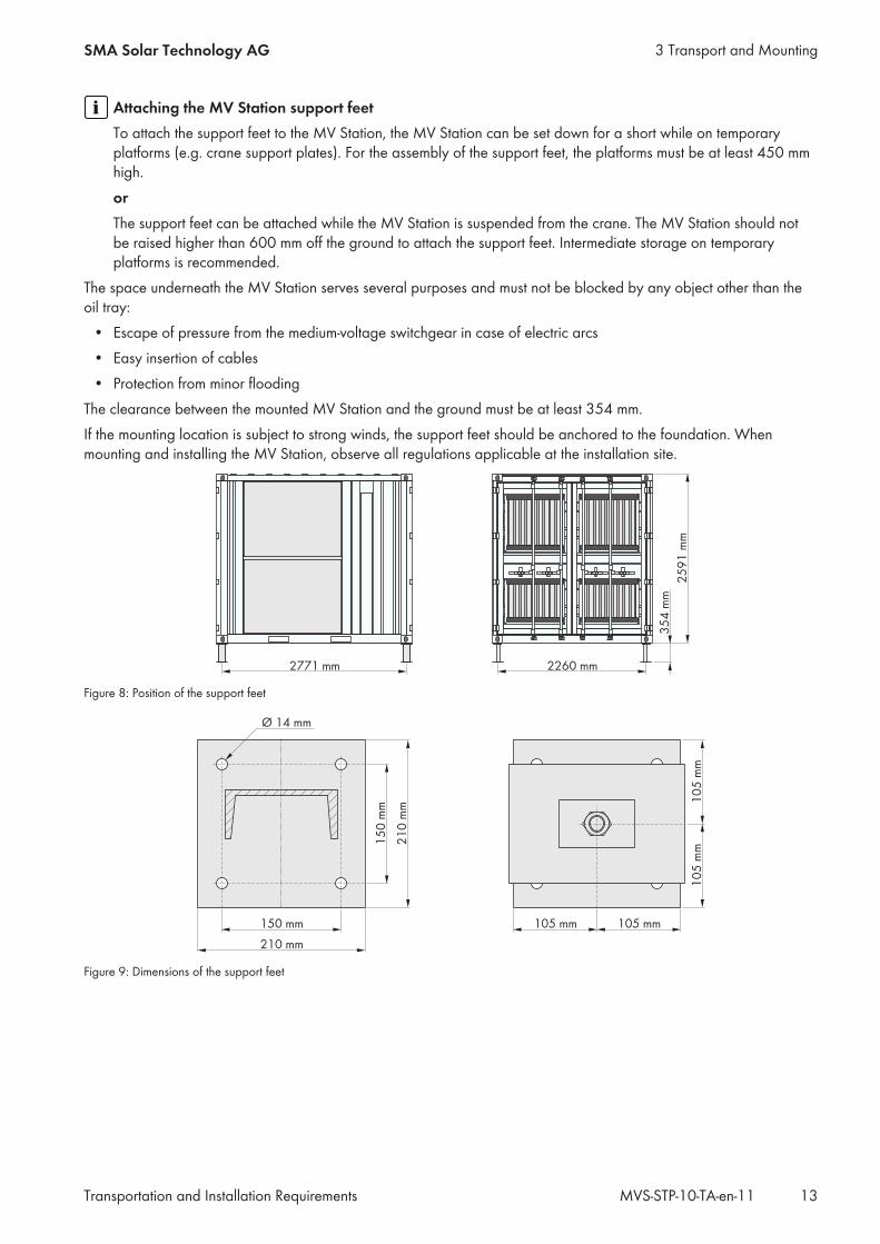
Attaching the MV Station support feetTo attach the support feet to the MV Station, the MV Station can be set down for a short while on temporaryplatforms (e.g. crane support plates). For the assembly of the support feet, the platforms must be at least 450 mmhigh.orThe support feet can be attached while the MV Station is suspended from the crane. The MV Station should notbe raised higher than 600 mm off the ground to attach the support feet. Intermediate storage on temporaryplatforms is recommended.
The space underneath the MV Station serves several purposes and must not be blocked by any object other than theoil tray:
• Escape of pressure from the medium-voltage switchgear in case of electric arcs• Easy insertion of cables• Protection from minor flooding
The clearance between the mounted MV Station and the ground must be at least 354 mm.If the mounting location is subject to strong winds, the support feet should be anchored to the foundation. Whenmounting and installing the MV Station, observe all regulations applicable at the installation site.
2771 mm 2260 mm
25
91
mm
35
4 m
m
Figure 8: Position of the support feet
Figure 9: Dimensions of the support feet
3 Transport and MountingSMA Solar Technology AG
Transportation and Installation Requirements 13MVS-STP-10-TA-en-11

• The support feet are connected to the MV Station via atwistlock.
2
3
1
• Any unevenness of the support surface can be compensated for using base plates.
3 Transport and Mounting SMA Solar Technology AG
Transportation and Installation RequirementsMVS-STP-10-TA-en-1114
4 Information for Installation
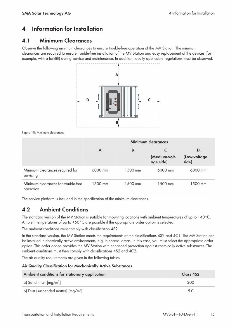
4.1 Minimum ClearancesObserve the following minimum clearances to ensure trouble-free operation of the MV Station. The minimumclearances are required to ensure trouble-free installation of the MV Station and easy replacement of the devices (forexample, with a forklift) during service and maintenance. In addition, locally applicable regulations must be observed.
A
B
CD
Figure 10: Minimum clearances
Minimum clearances
A B C(Medium-volt-age side)
D(Low-voltageside)
Minimum clearances required forservicing
6000 mm 1500 mm 6000 mm 6000 mm
Minimum clearances for trouble-freeoperation
1500 mm 1500 mm 1500 mm 1500 mm
The service platform is included in the specification of the minimum clearances.
4.2 Ambient ConditionsThe standard version of the MV Station is suitable for mounting locations with ambient temperatures of up to +40°C.Ambient temperatures of up to +50°C are possible if the appropriate order option is selected.The ambient conditions must comply with classification 4S2.In the standard version, the MV Station meets the requirements of the classifications 4S2 and 4C1. The MV Station canbe installed in chemically active environments, e.g. in coastal areas. In this case, you must select the appropriate orderoption. This order option provides the MV Station with enhanced protection against chemically active substances. Theambient conditions must then comply with classifications 4S2 and 4C2.The air quality requirements are given in the following tables.
Air Quality Classification for Mechanically Active Substances
Ambient conditions for stationary application Class 4S2
a) Sand in air [mg/m3] 300
b) Dust (suspended matter) [mg/m3] 5.0
4 Information for InstallationSMA Solar Technology AG
Transportation and Installation Requirements 15MVS-STP-10-TA-en-11

Ambient conditions for stationary application Class 4S2
c) Dust (precipitation) [mg/m3] 20
Installation sites where appropriate measures are taken to keep dust levels to a mini-mum
x
Installation sites where no special measures have been taken to reduce the sand ordust levels and which are not located in the vicinity of sand or dust sources
x
The air quality must comply with the following classification of air quality for chemically active substances:
Ambient conditions for stationary appli-cation
Class 4C1 Class 4C2
Mean value Threshold valueThreshold value
a) Sea salt ‒ Occurrence of salt spray
b) Sulfur dioxide [mg/m3] 0.1 0.3 1.0
c) Hydrogen sulfide [mg/m3] 0.01 0.1 0.5
d) Chlorine [mg/m3] 0.1 0.1 0.3
e) Hydrogen chloride [mg/m3] 0.1 0.1 0.5
f) Hydrogen fluoride [mg/m3] 0.003 0.01 0.03
g) Ammonia [mg/m3] 0.03 1.0 3.0
h) Ozone [mg/m3] 0.01 0.05 0.1
i) Nitrogen oxides [mg/m3] 0.1 0.5 1.0
Installation sites in rural or densely populatedareas with little industry and moderate trafficvolume
x x
Installation sites in densely populated areaswith industry and high traffic volume
‒ x
4.3 Installation
4.3.1 Design of the PV System with MV StationClosed electrical operating areaFor safety reasons, the PV system with the MV Station must be installed in a closed electrical operating area inaccordance with IEC 61936-1.
• Ensure that no unauthorized persons have access to the MV Station or the inverters.
4.3.2 Support surface☐ The support surface must be a dry and solid foundation, e.g. gravel.☐ For convenient working on the service platform on the medium-voltage compartment and trouble-free
maintenance, the provision of a level, paved surface is recommended. The surface should be in accordance withthe recommended minimum clearances for servicing operations.
☐ The support surface underneath the MV Station should be clean and firm to avoid any dust circulation.☐ In areas subject to strong precipitation or high groundwater levels, a drainage system must be implemented.
4 Information for Installation SMA Solar Technology AG
Transportation and Installation RequirementsMVS-STP-10-TA-en-1116

☐ To avoid the ingress of water as a result of rain, the MV Station is not to be installed in a depression.☐ To facilitate accessibility for servicing operations, the MV station is to be mounted at a height of no more than
0.5 m. Additional costs incurred during any servicing operations due to an increased mounting height must becovered by the customer.
4.3.3 Pea gravel groundThe support surface around the MV station must be prepared with a subgrade for drainage.
Installation of the MV Station with oil trayIf the MV Station is to be installed with an oil tray, the support surface must satisfy the following minimum requirements:☐ A pit must me dug out for the oil tray.☐ A drainage layer of 200 mm must be filled below the oil tray.☐ Once the oil tray has been positioned, the pit must be filled with gravel.☐ For convenient working on the service platform on the medium-voltage compartment and trouble-free
maintenance, the provision of a level, paved surface is recommended.
20
0m
m
Figure 11: Overview of the drainage layer below the oil tray
Installation of the MV Station without oil trayThe subgrade must meet the following minimum requirements:☐ The compression ratio of the subgrade must be 98%.☐ The soil pressure must be 150 kN/m2.☐ The unevenness must be less than 0.25%.☐ For convenient working on the service platform on the medium-voltage compartment and trouble-free
maintenance, the provision of a level, paved surface is recommended.☐ This area must have the following dimensions:
Position Dimensions
Width 6000 mm
Depth 6440 mm
4 Information for InstallationSMA Solar Technology AG
Transportation and Installation Requirements 17MVS-STP-10-TA-en-11

ABAB
Figure 12: Structure of the support surface
Position Designation
A Pea gravel ground as required
B Solid ground, e.g. gravel
4.3.4 Weight loadThe weight load on each of the support feet of the MV Station is 3000 kg.The support surfaces are to be designed accordingly.
4.3.5 Mounting optionsThe MV Station can be mounted on pile-driven steel pillars or concrete pillars.The type of mounting foundation is the responsibility of the customer.The service platform must be taken into account when planning the support surface (see Section 4.3.6, page 19).
4.3.5.1 Pile-driven steel pillarsMinimum length of the steel pillarsThe driven depth of the steel pillars must satisfy the structural requirements.
A CA AAB
Figure 13: Pile-driven steel pillars (example)
Position Designation
A Pile-driven steel pillars
B Solid ground, e.g. gravel
C Pea gravel ground
4.3.5.2 Concrete pillarMinimum lengths of the concrete pillarsThe below-ground depth of the concrete pillars must satisfy the structural requirements.
4 Information for Installation SMA Solar Technology AG
Transportation and Installation RequirementsMVS-STP-10-TA-en-1118

The concrete pillars must have the following properties:☐ The concrete pillars must be suitable for the weight of the product.☐ The concrete pillars must be mounted on solid ground.☐ The concrete pillars should have the following minimum dimensions:
75
0 m
m
500 mm
50
0 m
m
Figure 14: Dimensions of the concrete pillars (example)
A CA AAB
Figure 15: Concrete pillars (example)
Position Designation
A Concrete pillar
B Solid ground, e.g. gravel
C Pea gravel ground
4.3.6 Installation of the Temporary Service PlatformAreas for supporting the feet of the platform in front of the MV switchgear compartment must be provided for whenplanning the support surface.The weight load for the support feet is 150 kg each. The use of flagstones is recommended for the support surface.
• Recommended dimensions of flagstones: 400 mm x 400 mm x 60 mm
4 Information for InstallationSMA Solar Technology AG
Transportation and Installation Requirements 19MVS-STP-10-TA-en-11

2771 mm 1130 mm
70
5 m
m8
2 m
m8
2 m
m
22
60
mm
A
A
69
5 m
m6
95
mm
A
A
Figure 16: Position of the support feet of the service platforms
Position Designation
A Support feet of the work platform in front of the medium-voltage switchgear compartment** Only folded out temporarily
The service platforms are included in the specification of the minimum clearances.
Open areas underneath the MV StationThe open areas underneath the MV Station must not be blocked by any other installations or groundfill. The onlypermissible exception is the oil containment. The areas underneath the MV Station are needed for pressure dissipationin the event of arc faults.Disregarding this information can lead to personal injury or device failure. SMA Solar Technology AG does not acceptliability for any resulting damage.
0
I
0
I
0
I
Figure 17: MV°Station internal arc pressure
4.3.7 Recesses in the Support SurfaceRecesses for cable routing and for the oil tray must be provided in the support surface.
4 Information for Installation SMA Solar Technology AG
Transportation and Installation RequirementsMVS-STP-10-TA-en-1120

During planning of the recesses in the support surface, the positions of the support feet for the station and the serviceplatform must be taken into account.
60
0 m
m
21
13
mm
23
03
mm
23
94
mm
26
43
mm
14
6 m
m
742 mm
879 mm
1547 mm
427 mm
784 mm
839 mm
1085 mm
205 mm
1352 mm
1598 mm
1654 mm
2233 mm
A
A
A
A
B
C
0 mm0 mm
0 m
m
Figure 18: Position and dimensions of the recesses in the station container
Position Designation
A Recess underneath the low-voltage compartment for insertion of the low-voltage cables fromthe inverters:
• Maximum 30 cables, maximum cable cross-section: 95 mm2, maximum 30 cablesupport sleeves, diameter 14 mm to 68 mm
B Recess underneath the medium-voltage switchgear for insertion of the medium-voltage ca-bles:
• Maximum 3 single-core cables per cable panel, 3 cable support sleeves per cablepanel, diameter 14 mm to 68 mm
C Recess underneath the Inverter Manager for insertion of the data cables and grounding ca-bles:
• 3x for cable diameters 5 mm to 9 mm• 3x for cable diameters 9 mm to 13 mm• 4x for cable diameters 11 mm to 16 mm• 4x for cable diameters 14 mm to 21 mm
4.4 Oil ContainmentThe oil tray is only a component part of the MV Station if the option “Oil tray: With” was selected.
4 Information for InstallationSMA Solar Technology AG
Transportation and Installation Requirements 21MVS-STP-10-TA-en-11
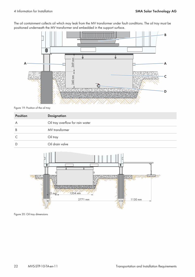
The oil containment collects oil which may leak from the MV transformer under fault conditions. The oil tray must bepositioned underneath the MV transformer and embedded in the support surface.
A
36
9m
m
A
B
C
D
34
0m
m
Figure 19: Position of the oil tray
Position Designation
A Oil tray overflow for rain water
B MV transformer
C Oil tray
D Oil drain valve
355 mm355 mm 1204 mm1204 mm
2771 mm2771 mm 1130 mm1130 mm
Figure 20: Oil tray dimensions
4 Information for Installation SMA Solar Technology AG
Transportation and Installation RequirementsMVS-STP-10-TA-en-1122
5 Electrical Connection
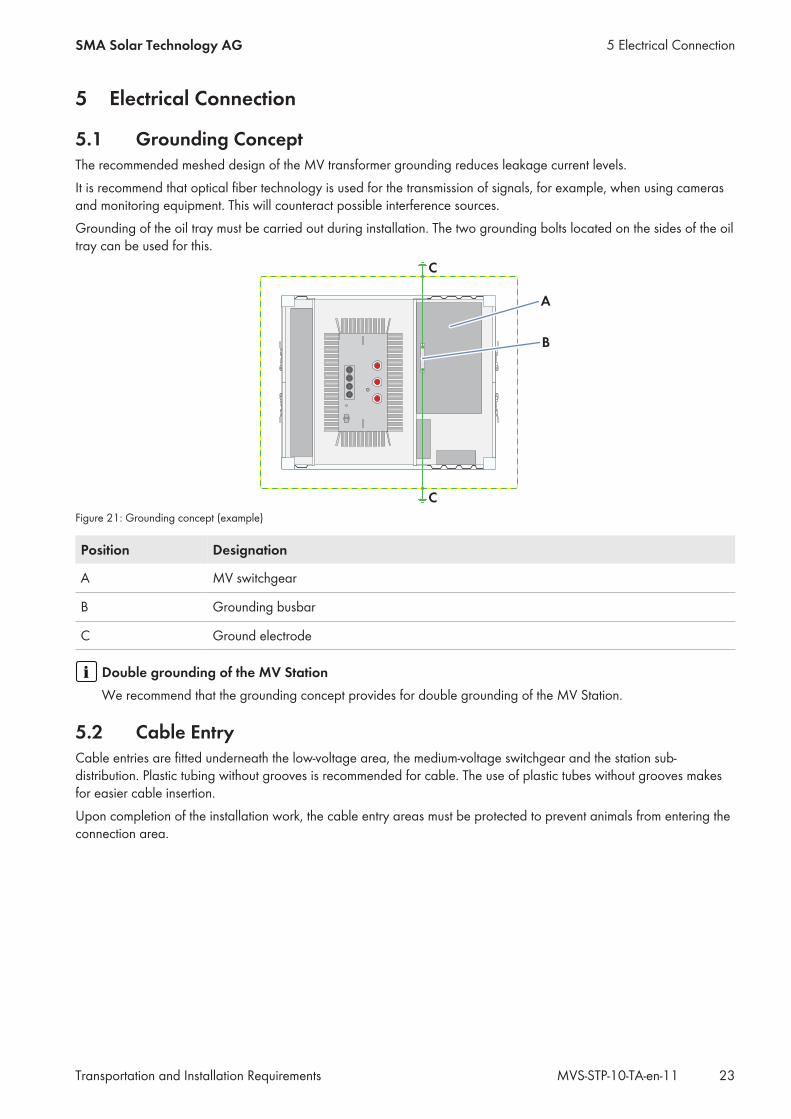
5.1 Grounding ConceptThe recommended meshed design of the MV transformer grounding reduces leakage current levels.It is recommend that optical fiber technology is used for the transmission of signals, for example, when using camerasand monitoring equipment. This will counteract possible interference sources.Grounding of the oil tray must be carried out during installation. The two grounding bolts located on the sides of the oiltray can be used for this.
A
B
C
C
Figure 21: Grounding concept (example)
Position Designation
A MV switchgear
B Grounding busbar
C Ground electrode
Double grounding of the MV StationWe recommend that the grounding concept provides for double grounding of the MV Station.
5.2 Cable EntryCable entries are fitted underneath the low-voltage area, the medium-voltage switchgear and the station sub-distribution. Plastic tubing without grooves is recommended for cable. The use of plastic tubes without grooves makesfor easier cable insertion.Upon completion of the installation work, the cable entry areas must be protected to prevent animals from entering theconnection area.
5 Electrical ConnectionSMA Solar Technology AG
Transportation and Installation Requirements 23MVS-STP-10-TA-en-11

5.3 Cable RequirementsTerminal Cable requirements
Low-voltage cables for inverters • Connection with tin-plated aluminum or copper terminal lug (for screwdiameter: 8 mm)
• Copper or aluminum cable• Cable cross-section: 16 mm2 to 95 mm2
Temperature-resistant cables (90°C) must be used if ambient temperaturesare higher than 40°C.
Medium-voltage cables • Connection with outer-cone angle plug type C
Communication interface Connection with Ethernet cables• The cables must be shielded and pair-twisted.• The cables must be at least category 5 (CAT 5).• Maximum cable length: 100 m
Ground electrode Cable cross-section copper cable: minimum 1 x 95 mm2 to maximum 2 x 95 mm2
Oil containtment grounding • Connection with tin-plated copper terminal lug• Cable cross-section copper cable: 50 mm2
5 Electrical Connection SMA Solar Technology AG
Transportation and Installation RequirementsMVS-STP-10-TA-en-1124

6 On-Site ServicesThe following supplies and performances are not included in the scope of delivery of the product:
• Transport to the construction site (can be carried out by us on request)• Crane or forklift for unloading the product at the construction site (SMA can perform the offloading on request)• Foundation for the product• Installation of the optional oil tray including oil tray grounding• Protective tubes for cable entry• Ground electrode or external grounding system• All mounting and connection work at the construction site• Door locks• Screws and wall plugs for the attachment of the support feet at the foundation• Protection test of the medium-voltage switchgear• Inspection of the grounding arrangement
The MV Station must be commissioned by SMA Solar Technology AG or an authorized service partner.
6 On-Site ServicesSMA Solar Technology AG
Transportation and Installation Requirements 25MVS-STP-10-TA-en-11

www.SMA-Solar.com