transport layer protocols tcp and udp
DESCRIPTION
Transport Layer Protocols TCP and UDP. Dr. Muazzam A. Khan. Applications. Packet. Packet. TCP. UDP. Packet. Packet. IP. Packet. Hardware. Transport Control Protocols. - PowerPoint PPT PresentationTRANSCRIPT

Transport Layer Protocols
TCP and UDP
Dr. Muazzam A. Khan

Dr. Muazzam A. Khan 2
Transport Control Protocols
The function of the Transport Layer is to insure packets have no errors and that all packets arrive and are correctly reassembled. Two protocols are used:
User Datagram Protocol. Provides unreliable, connectionless
delivery service using Internet Protocol. Application programs utilizing UDP
accepts full responsibility for packet reliability including message loss, duplication, delay, out of sequence, multiplexing and connectivity loss.
Transmission Control Protocol. Provides a reliable, connection delivery
service using Internet Protocol. It provides reliable packet delivery,
packet sequencing, error control, multiplexing.
Hardware
IP
Applications
TCP UDP
Packet
Packet Packet
PacketPacket
TCP and UDP pass IP packets to the applications

Dr. Muazzam A. Khan 3
Connectionless vs Connection-oriented Protocols
Connection-oriented – Two computers connect before sending any data, sender lets receiver know that data is on the way; recipient acknowledges receipt of data (ACK) or denies receipt (NACK). The ACKing and NACKing is called handshaking. (Type supported by TCP). Reliable, but carries overhead burden.
Connectionless – Computers involved know nothing about each other or the data being sent. Makes no attempt to cause networks senders and receivers to exchange information about their availability or ability to communicate with one another, “best effort” delivery. (Type supported by IP, UDP). Not reliable, but faster and may be good enough. Also upper layer apps may worry about errors and reliability processing, so no need to do it twice.

Dr. Muazzam A. Khan 4
Transport Layer Ports
Both TCP and UDP use port numbers to pass to the upper layers. Port numbers have the following ranges:
0-255 used for public applications, 0-1023 also called well-known ports, regulated by IANA (Internet assigned numbers authority).
Numbers from 255-1023 are assigned to marketable applications 1024 through 49151 Registered Ports, not regulated. 49152 through 65535 are Dynamic and/or Private Ports .
Port numbers are used to keep track of different conversations that cross the network at the same time.
Port numbers identify which upper layer service is needed, and are needed when a host communicates with a server that uses multiple services.

Dr. Muazzam A. Khan 5
9 Discard Discard all incoming data port7 Echo Echo19 Chargen Exchange streams of data port20 FTP-Data File transfer data port21 FTP-CMD File transfer command port23 Telnet Telnet remote login port25 SMTP Simple Mail Transfer Protocol port53 DOMAIN Domain Name Service79 Finger Obtains information about active users80 HTTP Hypertext Transfer Protocol port88 Kerberos Authentication Protocol110 POP3 PC Mail retrieval service port119 NNTP Network news access port161 SMTP Network Management179 BGP Border Gateway Protocol513 Rlogin Remote Login In
Port Application Description
Some Well-Known TCP Ports

Dr. Muazzam A. Khan 6
Destination PortSource Port
Ports for Clients
8080 1032
1. Client requests a web page from server 1032
2. Server responds to client
Clients and servers both use ports to distinguish what process each segment is associated with.
Source ports, which are set by the client, are determined dynamically, usually a randomly assigned a number above 1023.

Dr. Muazzam A. Khan 7
FCSPREAMBLE DESTINATION ADDR00 00 1B 12 23 34
SOURCE ADDR 00 00 1B 09 08 07
FIELDTYPE
ETHERNET
6Source IP Address; 128.66.12.2
Destination IP Address; 128.66.13.1
IP Header
TCP Header
IPHEADER
TCPHEADER DATA
Source Port 5512 Destination Port
23
Telnet
DATA LINKLAYER
NETWORKLAYER
TRANSPORTLAYER
APPLICATIONLAYER
Protocols and Port Numbers

Dr. Muazzam A. Khan 8
FCSPREAMBLE DESTINATION ADDR00 00 1B 12 23 34
SOURCE ADDR 00 00 1B 09 08 07
FIELDTYPE
ETHERNET
17Source IP Address; 128.66.12.2
Destination IP Address; 128.66.13.1
IP Header
UDP
IPHEADER
TCPHEADER DATA
Source Port 5512 Destination Port
69
FTP
DATA LINKLAYER
NETWORKLAYER
TRANSPORTLAYER
APPLICATIONLAYER
Protocols and Port Numbers

Dr. Muazzam A. Khan 9
TCP Operation TCP is a connection-oriented protocol. TCP provides the following major services to the upper protocol
layers: Connection-oriented data management to assure the end-to-end transfer of
data across the network(s). Reliable data transfer to assure that all data is accurately received, in
sequence and with no duplicates. Stream-oriented data transfer takes place between the sender application and
TCP and the receiving application and TCP. To stream is to send individual characters not blocks or frames.
Prior to data transmission, hosts establish a virtual connection via a synchronization process. The synch process is a 3-way “handshake”, which ensures both sides are ready to transfer data and determines the initial sequence numbers.
Sequence numbers give hosts a way to acknowledge what they have received. TCP header contain SYN bits, or flags, to achieve this.

Dr. Muazzam A. Khan 10
TCP Synchronization or 3-Way HandshakeTCP is a connection oriented protocol. Communicating hosts go through a synchronization process to establish a virtual connection. This synchronization process insures that both sides are ready for data transmission and allows the devices to determine the initial sequence numbers.
Send ACKACK = y + 1
Receive SYNSeq = x
Send SYNSeq = y
ACK = x + 1Receive SYN
Seq = yACK = x + 1
Send SYNSeq = x
Receive ACKACK = y + 1
Sequence numbers are reference numbers between the two devices. The sequence numbers give each host a way to ACK the SYN, so the receiver knows which connection request the sender is responding to.
Dr. Muazzam A. Khan 11
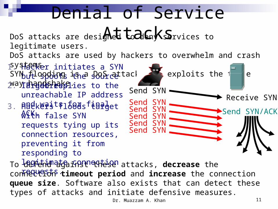
Denial of Service Attacks
1. Hacker initiates a SYN but spoofs the source IP address.
DoS attacks are designed to deny services to legitimate users.DoS attacks are used by hackers to overwhelm and crash systems.SYN flooding is a DoS attack that exploits the three way handshake.
To defend against these attacks, decrease the connection timeout period and increase the connection queue size. Software also exists that can detect these types of attacks and initiate defensive measures.
Send SYNReceive SYN
Send SYN/ACKSend SYNSend SYNSend SYNSend SYNSend SYN
2. Target replies to the unreachable IP address and waits for final ACK.
3. Hackers floods target with false SYN requests tying up its connection resources, preventing it from responding to legitimate connection requests.

Dr. Muazzam A. Khan 12
TCP Windows and Flow Control Data often is too large to be sent in a single segment. TCP splits the
data into multiple segments. TCP provides flow control through “windowing” to set the pace of
how much data is sent at a time – IE how many bytes per window, and how many windows between ACKs.
Window Size = 1 Window Size = 3

Dr. Muazzam A. Khan 13
Sliding window refers to the fact that the window size is negotiated dynamically during the TCP session.
Window size determines the amount of data that you can transmit before receiving an acknowledgment. This is how TCP assists in congestion control.
Windowing and Window Size
If the source receives no acknowledgment, it knows to retransmit at a slower rate.
Expectational acknowledgment means that the acknowledgment number refers to the octet that is next expected.
Fast enough for you?
I didn’t get all of that,
slow down.

Dr. Muazzam A. Khan 14
Sequence and ACK Numbers Each TCP segment is numbered before transmission so that the
receiver will be able to properly reassemble the bytes in their original order.
They also identify missing data pieces so the sender can retransmit them.
Only the missing segments need to be re-transmitted.
Positive Acknowledgement and RetransmissionTCP utilizes PAR to control data flow and confirm data delivery.
Source sends packet, starts timer, and waits for ACK. If timer expires before source receives ACK, source retransmits the
packet and restarts the timer.

Dr. Muazzam A. Khan 15
VERS
FCSPREAMBLE DESTINATIONADDRESS
SOURCEADDRESS
FIELDTYPE
ETHERNET
0-65535
2668 4
HLEN TOS Total Length4 bits 4 bits 8 bits 16 bits
Identification16 bits
Flags3 bits
Fragment Offset13 bits
TTL8 bits
Protocol8 bits
Checksum16 bits
Source IP Address32 bits
Destination IP Address32 bits
IP Options(if any)32 bits
TCP Data (if any)
0 15 16 31
Source Port Destination Port
Sequence Number
Acknowledgement Number
Offset U A P R S FReserved Receive Window Size
Checksum Urgent Pointer
16 bits 16 bits
32 bits
32 bits
4 bits 6 bits 16 bits
16 bits 16 bits
IP Header
TCP Header
IP Datagram
Options (if any)
DATAIPHEADER
TCPHEADER
TCP Encapsulation

Dr. Muazzam A. Khan 16
Number of the calling port Number of the called port
Used to ensure correct sequencing of the
arriving data
Next expected TCP octet
Number of 32-bit words in the header
set to zero
Control setup and termination of session
Number of octets sender is willing to accept Indicates the end of the urgent data
Upper layer protocol data
TCP Segment Format
Dr. Muazzam A. Khan 17
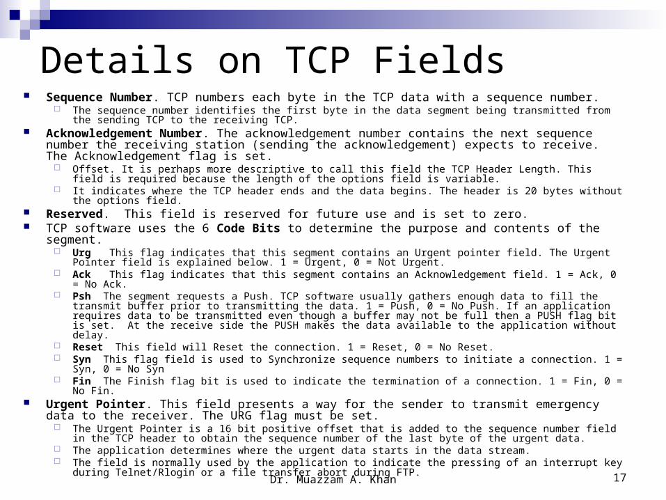
Details on TCP Fields Sequence Number. TCP numbers each byte in the TCP data with a sequence number.
The sequence number identifies the first byte in the data segment being transmitted from the sending TCP to the receiving TCP.
Acknowledgement Number. The acknowledgement number contains the next sequence number the receiving station (sending the acknowledgement) expects to receive. The Acknowledgement flag is set.
Offset. It is perhaps more descriptive to call this field the TCP Header Length. This field is required because the length of the options field is variable.
It indicates where the TCP header ends and the data begins. The header is 20 bytes without the options field. Reserved. This field is reserved for future use and is set to zero. TCP software uses the 6 Code Bits to determine the purpose and contents of the segment.
Urg This flag indicates that this segment contains an Urgent pointer field. The Urgent Pointer field is explained below. 1 = Urgent, 0 = Not Urgent.
Ack This flag indicates that this segment contains an Acknowledgement field. 1 = Ack, 0 = No Ack. Psh The segment requests a Push. TCP software usually gathers enough data to fill the transmit buffer prior
to transmitting the data. 1 = Push, 0 = No Push. If an application requires data to be transmitted even though a buffer may not be full then a PUSH flag bit is set. At the receive side the PUSH makes the data available to the application without delay.
Reset This field will Reset the connection. 1 = Reset, 0 = No Reset. Syn This flag field is used to Synchronize sequence numbers to initiate a connection. 1 = Syn, 0 = No Syn Fin The Finish flag bit is used to indicate the termination of a connection. 1 = Fin, 0 = No Fin.
Urgent Pointer. This field presents a way for the sender to transmit emergency data to the receiver. The URG flag must be set.
The Urgent Pointer is a 16 bit positive offset that is added to the sequence number field in the TCP header to obtain the sequence number of the last byte of the urgent data.
The application determines where the urgent data starts in the data stream. The field is normally used by the application to indicate the pressing of an interrupt key during Telnet/Rlogin or
a file transfer abort during FTP.

Dr. Muazzam A. Khan 18
UDP/TCP Operation Comparison There are two protocols at Layer 4
– TCP and UDP. Both TCP and UDP use IP as their underlying protocol.
TCP must be used when applications need to guarantee the delivery of a packet. When applications do not need a guarantee, UDP is used.
UDP is often used for applications and services such as real-time audio and video. These applications require less overhead. They also do not need to be re-sequenced since packets that arrive late or out of order have no value.
TCP UDPConnection-oriented delivery
Connectionless delivery, faster
Uses windows and ACKs
No windows or ACKs
Full header Smaller header, less overhead
Sequencing No sequencing
Provides reliability Relies on app layer protocols for reliability
FTP, HTTP, SMTP, and DNS
DNS, TFTP, SNMP, and DHCP
0 – 15 16 - 31 31 - 47 48 – 63 64
Source Port Destination Port Length Checksum Data…
UDP segment format

Dr. Muazzam A. Khan 19
User Datagram Protocol
UDP is a connectionless, unreliable Transport level service protocol. It is primarily used for protocols that require a broadcast capability, i.e RIP.
It provides no packet sequencing, may lose packets, and does not check for duplicates. It is used by applications that do not need a reliable transport service. Application data is encapsulated in a UDP header which in turn is encapsulated
in an IP header. UDP distinguishes different applications by port number which allows
multiple applications running on a given computer to send /receive datagrams independently of one another.
FCS
IP HEADERPREAMBLE
DESTINATIONADDRESS
SOURCEADDRESS
FIELDTYPE
ETHERNET
8-15002668 4
UDP Source Port
0 15 16 31
UDP Message Length
Data
UDP Destination Port
UDP Checksum
. . .
UDP DATAGRAM

Dr. Muazzam A. Khan 20
UDP Port NumbersEcho 7 Echo user datagram back to userDiscard 9 Discard user datagramsDaytime 13 Report time in a user friendly fashionQuote 17 Return "Quote of the day"Chargen 19 Character generatorNameserver 53 Domain Name ServerSql-Net 66 Oracle Sequel NetworkBOOTPS 67 Server port to download configuration informationBOOTPC 68 Client port to receive configuration informationTFTP 69 Trivial File Transport ProtocolPOP3 110 Post Office Protocol - V3SunRPC 111 Sun Remote Procedure CallNTP 123 Network Time ProtocolSNMP 161 Used to receive network management queriesSNMP-trap 162 Used to receive network problem reports.IRC 194 Internet Relay ChatIPX 213 IPX - IP TunnelingSysLog 514 System LogRIP 520 Routing Information ProtocolNFS 2049 Network File Service