transmitting valve coolerwith increased', turbulence … bound... · a transmitting valve...
TRANSCRIPT

FEBRUARY 1949
A TRANSMITTING VALVE COOLER WITH INCREASED', TURBULENCEOF THE COOLINGWATER
by M. J. SNIJDERS. 621.396.694.032.42
Although air-cooling has certain advantages for transmitting valves, water-cooling hasthe preference where the most intensive cooling effect is required, for example in trans-mitters working on very short waves. It appears that considerable improvement on theusual methods of cooling can he obtained by increasing the turbulence of the water inthe cooler. One very effective method of achieving this is to inject the water into thecooler by means of concentrio rings with jets arranged round the anode; the jets of waterset up considerable turbulence in the water within the cooler. This method has beenadopted for valve types PAW 12/15 and TAW 12/35, as it has been found in practicethat, above a certain anode température (about 90 Oe), a layer of copper oxide formson the surface of the anode, which is such a poor thermal conductor that the lattertends to become overheated. In comparison with the old type of cooler, for the sameHowof water per minute and the same dissipation, the spray method results in the peakanode temperature remaining about 40 °c lower and therefore well below the criticalvalue of 90 °C. The dimensions of both types of cooler are the same and the new systemcan therefore be easily incorporated in existing equipment. The increased cooling effectprovided by the system under review offers the possibility of obtaining a given trans-mission power from smaller valves than heretofore and/or at lower wavelengths.
Transmitting valves whose dissipation lies abovea certain value are usually artificially cooled, thishaving the effect of considerably reducing the mini-mum practical dimensions of a given valve; thisdissipation value lies at about 3 kW.
In most cases this cooling is effected by arrangingfor a flow of water along the anode, which con-stitutes part of the wall of the valve itself (fig. 1).According to another method, which is beingapplied more and more of late, air is blown along
K tin
~ f f ~
Fig. 1. An = anode of transmitting valve mounted in coolerK through which water flows,
the anode, in this case provided with suitable cool-ing fins. In an earlier issue of this journal 1) a des-cription was given of a new form of cooling fins anda special method of air distribution which willpermit of air-cooling even with the largest trans-mitting valves. As pointed out in that article, air-cooling has certain distinct advantages over water-cooling and there can be no doubt that it will super-sede the latter in many instances. Nevertheless,water-cooling will often be given preference, espe-cially when the valve is to operate on the higherfrequencies, in which case the ratio of outputpower to dissipated power is mueh less favourablethan on the lower frequencies. Furthermore, at,very high frequencies, capacitances have to be keptas low as possible, not only between the electrodesin anyone valve, but also between the anodes of twovalves in a push-pull circuit, mounted close to-gether for compactness. All this means that everyeffort is made to keep the dimensions of both valveand cooler as small as possible; as far as the valveitself is concerned, this in turn leads to high specifieloads (i.e. dissipation per sq. cm anode area) andtherefore also highly efficient cooling. As regardsthe latter, the water-cooler has the advantage of itssmaller dimensions in comparison with the air-cooler, so that, if the maximum dissipation of theanode is demanded, water-cooling will be preferred.In the following we propose to discuss the newmethod of cooling more filly. ,
1) H. de Brey and H. Rinia, An improved method for theair-cooling of transmitting valves, Philips Techn. Rev. 9,171-178, 1947 (No. 6).
239
•

240 PHILIpS TECHNICAL REVIEW VOL. 10, No. 8
In an "open" system the used cooling water isallowed to run .to waste. .
In 'the closed system the ,used water, .the tem-perature of which has been raised, is cooled downin a special cooling device and used again; in other,words a fixed quantity ~f water is kept in circula-tion.
For medium-sized transmitters; in which thewater consumption is not very high, the simplestform of cooling system, i.e. the ?pen typ.e, is usu-ally adopted, provided the quality of the availablewater supply is good enough, that is to say suffi-ciently free from elements that tend to fur theanodes, (this point will be referred to in detail later).Boiler scale is a very bad conductor of heat andtherefore reduces the cooling effect, with the resultthat the valve ultimately runs the risk of beingoverheated. If only "hard" water is available thenthe closed system, where all the injurious consti-tuents forming the scale speedily disappear, willhave to be used. Moreover, even the initial depositcan be avoided by filling the cooling system withdistilled water; it is only necessary to top up thewater occasionally, to make good the small lossesdue to evaporation and leakage.In large transmitters, requiring for instance a
flow of water of about 500 litres (100 gallons) perminute, the closed system will always be preferablein view of the saving to be made on the cost of thepure water required for the open system.
Various methods are available for use in connec-tion with the "return cooling" of the used water:small installations mostly employ an equipment verysimilar to the cooling system of 'a motor-car; in thelarger transmitting stations use may be made ofcooling towers, reservoirs or surface coolers inwhich the circulating (primary) water imparts itsheat to running (secondary) water. The lattersolution is shown infig. 2 (the closed type of systememployed in the main Netherlands broadcastingstations).The purity of the secondary cooling water need
not be particularly high, as experience has shownthat deleterious substances are not deposited in thereturn cooler, this being due to the fact that thetemperature of the primary water is fairly low (atmost 30°C). The secondary supply may thereforeconsist of unpurified well-water, which is eompa- Possible causes of deposit on the anoderatively cheap. We have already' mentioned the possibility ofAnother advantage ofthe closed system, provided furring in the case of the open cooling system. It .
distilled water is used, is evident from what follows. might be inferred, in view of the foregoing, thatThe anode of the transmitting valve to be cooled there would be no questoin of any kind of depositcarries a very high D.C. potential with respect to .••.)n ,a closed cooling system containing distilled
. Open and closed cooling systems earth (possibly 20 kV) and also a high superim-'posed h.f. alternating voltage. Now, for the purposesof electrical insulation, the cooling water for. theanode is fed and carried away through long insu-lating tub-es. In order to save space these tubes
/--------------------------. ----"I TA1S'/1OO I II IIIIIII
It . I
'-----------------------------_/4087/rnin.
RT
SJ969
Fig. 2. Diagram of the closed coolingsystem as employed inthe Netherlands broadcasting stations. The flow of the pri-mary water is indicated by single arrows; that of the secon-dary water by double ones. P = pump, 1 = output stage,11 = driver stage, S = coiled ceramic tube (for electrical'insulation), R = reservoir, T = return cooler.The output stage (I) comprises four valves type TA
18/100, plus two reserve valves not shown in the diagram.When the latter are put into service the cooling water isswitched over simultaneously with the electrical connections.The driver stage (II), incorporating four PAW 12/15 valves,is arranged differently: in this case the cooler of each of thefunctional valves is connected in series with that of theassociated reserve valve. In the figure only one of the fourpairs is shown. At the point F a filter may be fitted (to be~scussed later). .
(preferably made of ceramic material) are usuallyarranged in the form of a coil (8 fig. 2). Althoughthe tubes themselves are non-conductive, there isnevertheless a certain leakage of current through _the stream of water. This loss can be limited to a .minimum by filling the closed system with distilledwater, which has a low conductivity. The efficiencyof the transmitter is thus considerably _improved.

FEBRUARY 1949 TRANSMITTING VALVE COOLER 241
water, but in practice furring does actually takeplace, owing to the circulating water picking upsubstances from the walls of the system, thus form-ing compounds which are deposited on the anode.For example, if the water is in direct contact withconcrete, as may be the case if a reservoir as repre-sented in fig. 2 is used, boiler scale will form on theanode; such reservoirs should therefore always bclined with chlorinated rubber paint to prevent thewater from coming into direct contact with theconcrete.It has been found at a number of transmitting
statjons that, even though such precautions are takenand distilled water is used, a heat-insulating deposit- albeit not boiler scale - tends to form on the anode.
In fact a hard, black deposit has been found onthe anodes of the PAW 12/15 and TAW 12/35(fig. 3) as employed in different broadcasting sta-tions where closed cooling systems were in use;this layer proved to be copper-oxide (CuO), which,although not such a poor conductor of heat as scale,may nevertheless lead to overheating of the valve.
Measures to prevent the deposit of copper-oxide
These copper-oxide deposits can of course beremoved from time to time by sanding or pickling,butsuch operations, involving as they do the dismantlingof the valve and subsequent re-inserting in thecooler, incur considerable risk of breakage (notonly of the glass, but also of the tungsten filament,which in time becomes brittle).
One way of preventing the occurrence of copper-oxide would be to arrange matters so that at leastone of the elements of which it consists cannotappear at the anode. Since the water is exposed tothe air at a number of points (as in the reservoir,see fig. 2), the solution of oxygen can hardly beprevented. The presence of copper itself is even moredifficult to avoid, as in the first place the anode ismade of this material and, moreover, the wholecooling circuit, pumps, cocks and other equipmentmust necessarily consist of non-corroding material.Tinning of such components, as well as of the anodeitself, would effectively prevent all direct contactbetween copper and water, but we found a muchsimpler method of preventing the formation ofcopper-oxide, consisting in a reduction in the tem-perature of the anode by intensifying the cooling.An improved type of cooler, which forms thesubject of the present article, has been speciallydeveloped for this purpose.In fact there are a number of indications that a
reduction in the anode t emp er a t u r e reducesthe formation of copper-oxide and that b e-
Iowa certain temperature limit it is almostentirely absent. The indications in question,as observed in a number of broadcasting stations,are the following:
Fig. 3. The three transnnttmg valves mentioned in thisarticle. From left to right: the pentode PAW 12/15, thetriode TAW 12/35 ann the triode TA 18/100.
1. Copper-oxide appeared more abundantly at thehottest parts of the anode.
2. More copper-oxide per unit of time was pro-duced in heavily loaded valves of the type PAW12/15 than in the more lightly loaded valves.
3. Type TA 18/100 valves (fig. 3) as used in the sam«transmitter and employing the same coolingwater as the two previously mentionedPA W12/15valves (see fig. 2) showedno copper-oxide deposit,even under the heaviest loads. In fact, the anodetemperature of the valves TA 18/100 appearedto be lower in this case than that of the valvesPAW 12/15, as was proved by provisional mea-surements by means of thermo-couples solderedto the anodes. For the results of the measurementssee table 1. (For practical reasons these measure-ments were carried out under staticload 2), calcu-
2) The temperature under static load is less uniformly dis-tributed over the anode than in the caseofdynamic loading.This point is dealt with more fully in connection with themore accurate measurements described in the followingparagraphs; the values given in table I are the outcomeof less provisional, precise measurement.
242 PHILlPS TECHNICAL REVIEW VOL. 10, No. 8
lated to give the same dissipation as in the mostheavily loaded valves in the transmitter.The formation of copper-oxide appeared to cease
at temperatures between 55 and 94°C; accordingto later measurements the actual limit is in factabout 90 °C.
Table I. Measured temperatures of transmitting valves. t',. t" = temperature of cooling water at inlet and outlet of the -cooler respectively, A = flow of water, Ptot = total dissipa-tion calculated from t"-t' and A, ta = anode temperaturemeasured with thermo-couple (roughly at the hottest place).
Type PAW 12/15 TA 18/100
t' eç) 20 20t" (0C) 30 26A (lfmin) 12 90Ptot (kW) 8.4- 37.7ta eC) 94 55
The cooling of the valve PAW 12/15 in comparisonWith that of the valve TA 18/100
The problem, therefore, was how to keep theanode of the PAW 12/15 at a sufficiently low tem-perature.
The differences in the anode temperature as shownin the above 'table are not to be accom:Îted for bythe specific anode load of the PAW 12/15 in thatparticular transmitter being higher than that ofthe TA 18/100, for as a matter of fact the specificload on the PAW 12/15 was 23 W/cm2 and that onthe TA 18/100 26 W/cm2•
The reason for the difference in temperature isapparent, however, when thc speeds of flow of thewater are compared: this speed, v, is obtained fromthe quotient of the flow A and the cross-sectionalarea 0 of the annular water-jacket surrounding theanode. In both cases 0 was 10.6 cm2,a;d the valuesof A, as shown in the table, were 12 and 90 I/min,or 0.2 X 10⁻³ and 1.5 X 10⁻³ m3/sec respectively,so that, for the PAW 12/15: .v = 0.2 X 10⁻³/10.6 X 10-4 - 0.19 m/sec.and for the TA 18/100:v = 1.5 X 10⁻³/10.6 X 10-4 - 1.4 m/sec.
In the case of a laminary flow of cooling li-quid over a heated surface the transfer of heatfrom the latter to the liquid takes place exclusivelyby conduction (radiation may he ignored here);now, the coefficient of thermal conductivity - i.e.the amount of heat transferred to the cooling agentper unit of the surface area, per unit of time andper degree difference in, temperature - is inde-pendent of the rate offlow of the medium.
However, even at the lower of the .two above-mentioned speeds the flow of water is turbulentand the volume elements of the water thereforeacquire a component of speed in a radial direc-tion as well as axial speed v as calculated above; thehotter volume-elements are thus transported to thecolder places and vice versa. Due to this radialcomponent convection occurs, as a result ofwhich the coefficient of thermal conductivity ismuch greater than when attributed to conductiononly. Furthermore, turbulence in the water involvesanother factor, in that, owing to the eddies, eachaqueous element may come into repeated contactwith the surface to be cooled, taking up an amountof heat each time. Thus the stronger the turbulence,the smaller the differences in temperature occurringin a radial direction within the water-jacket.The radial component of the speed of flow re-
quired for an efficient transfer of heat increaseswith the axial speed v of the. water 3). It mightbe possible to increase the speed in the case of thePAW 12/15, for instance by increasing the flow ofwater A per minute, but such a solution would beuneconomical in many respects. Another way outwould be to reduce the cross-section 0, but inpractice there are limits in this direction consideringthat the anode and water-jacket are only 3 mm(l/S") apart, whilst allowance must also he made forthe fact that the anode is not always perfectlycylindrical.Other means have therefore to be sought to
increase the turbulence of the water in the cooler.
The spray cooler
A very high degree of turbulence can be obtainedby inj ecting the water into the cooler·in a suitablemanner, and fig. 4 gives details of a very practicalmethod. The water is sprayed from a number ofjets placed in a ring röund the anode and sets upinside -the filled cooler a violent circulation themain direction of which - accompanied by sub-sidiary eddies in other directions - is indicatedby the dotted lines in the diagram.
Fig. 5 shows the ultimate arrangement as appliedto the valve PAW 12/15; a similar form of cooler hasalso been developed for the valve TAW 12/35. Thewater enters a channel at 1 which is drilled in thebronze bottem of the cooler and subsequentlybranches into four ducts, each of which leads to avertical tube through which the water reaches threejet-rings. Finally, the water leaves the cooler at 5.
3) It is actually less than proportional, e.g, in some casesproportional to v'I.; see A. Schaek, Der industrielleWärmeübergang, Düsseldorf 1940, 2nd edition, p, 60.

, FEBRUARY 1949 TRANSMITTING VALVE COOLER 243
The external dimensions of the cooler are exactlythe same as those of the old type.
Calculations
The design of the new cooler is based on the sameflow of water as the old type (12 I/min = 2.64gallons/min = 200 cm3/sec for the. valve PAW12/15), so that it may ~e substituted for existing
Fig. 4. Principle of the spray cooler. R = injector rings pro-ducing jets of water S, which keep the cooling water in violentmotion. An = anode, K = cooling jacket. .
equipment without necessitating the installation ofpumps for larger quantitiesjminute or higher prcs-sures,The speed of flow of the water, Vo (in m/sec),
passing from, the jets is rendered by the expression
Vo = y2gh,
where g is the gravitational acceleration (in m/sec2)and h the difference between the pressures (in mwater column) in'front of and behind the jets. If hbe the total drop in pressure in the cooler--for which we maintain of the old cooling device(h = 1 m in the case of the value PAW 12/15) --the exit speed will be
Vo= y2 X 9.81 X 1 = 4.4 m/sec.
Since there is also a certain drop in pressure inthe other parts of the cooler and h is thus slightlyless than 1 m, we shall assume that Vo ~ 4 m/sec.
From this assumed flow of water it follows thatthe jets must have a total orifice area of 200/400= 0.5 cmê, The question as to the most suitablenumber of holes into which this area can be dividedis governed by the fact that, on the one hand, alarge number of holes promotes more uniformcooling, whereas on the other hand -- and this is a
more practical consideration small holes aremore liable to become. clogged.
In view of this latter factor, a diameter. of 1 mmhas been taken for the jets, necessitating 60 holesto give a total area of 0.5 cm'',
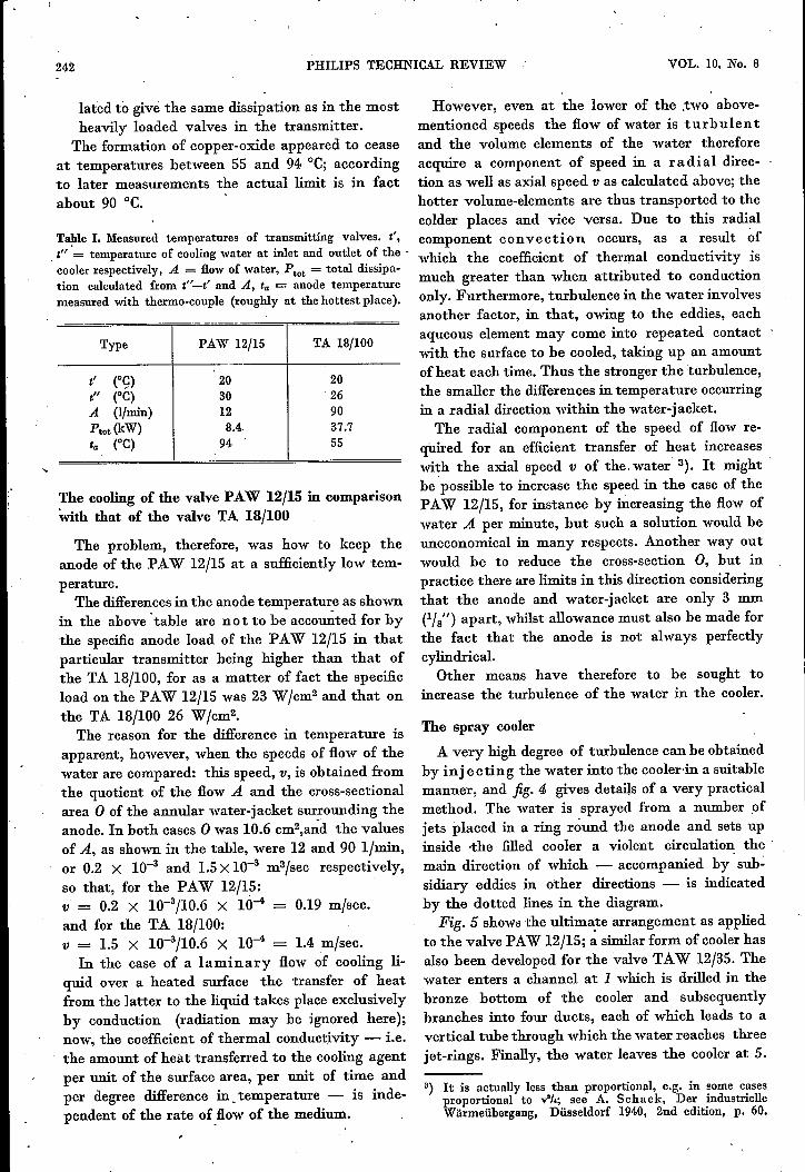
To eliminate any possible risk of stoppages thesimple filter shown infig. 6 has been designed, Thisis :fitted at the inlet of the cooler (at F in :fig. 2) ..
Other points to he tak~n into consideration werethe most suitable number of rings among which todivide the 60 jets, the most satisfactory height inrespect of the anode at which to place them, the .most effective angle for the jets of water, etc. 'I'heseproblems were solved experimentally, mainly 'withthe aid of temperature measurements (discussed in
4----\--_\_'~
3-----T-~~~~~_+-~
Fig. 5. Top view and vertical cross-section of the spraycooler. The cooling water enters at 1, flows through duct 2and branches into four tubes 3, thus reaching the three jet-rings 4 and ultimately leaving the cooler at 5.
244 PHILIPS TECHNICAL REVIEW VOL. 10, No.r8
the next paragraph) taken with a cooler so con-structed that the factors in question were variable.As will be seen from fig.5, the number of rings hasbeen fixed at three. The most satisfactory angle forthe jets of water was found to be obliquely upwardstowards the anode, at an angle of 30° from thevertical.
5.38.1;8
Fig. 6. Simple filter made of metal gauze. It is included in thewater system at the inlet of the spray cooler (at F in fig. 2)and can be easily mounted on the latter (see left-hand andcentre' valves in fig. 3).
Measurements
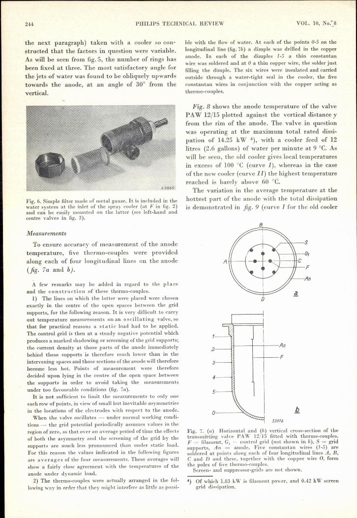
To ensure accuracy of measurement of the anodetemperature, five thermo-couples were providedalong each of four longitudinal lines on the anode(fig. 7a and b).
A few remarks may be added in regard to the p I a ceand the construction of these thermo-couples.
1) The lines on which the latter were placed were chosenexactly in the centre of the open spaces between the gridsupports, for the following reason. It is very difficult to carryout temperature measurements on an oscillating valve, sothat for practical reasons a static load had to be applied.The control grid is then at a steady negative potential whichproduces a marked shadowing or screening of the grid supports;the current density at those parts of the anode immediatelybehind these supports is therefore much lower than in theintervening spaces and those sections of the anode will thereforebecome less hot. Points of measurement were therefore.decided upon lying in the centre of the open space betweenthe supports in order to avoid taking the measurementsunder too favourable conditions (fig. 7a).It is not sufficient to limit the measurements to only one
such row of points, in view of small but inevitable asymmetriesin the locations of the electrodes with respect to the anode.
When the valve oscillates - under normal working condi-tions - the grid potential periodically assumes values in theregion of zero, so that over an average period of time the effectsof both the asymmetry and the screening of the grid by thesupports are much less pronounced than under static load.For this reason the values indicated in the following figuresare averages of the four measurements. These averages willshow a fairly close agreement with the temperatures of theanode under dynamic load.
2) The thermo-couples were actually arranged in the fol-lowing way in order that they might interfere as little as possi-
bIe with the flow of water. At each of the points 0-5 on thelongitudinal line (fig. 7b) a dimple was drilled in the copperanode. In each of the dimples 1-5 a thin constantanwire was soldered and at 0 a thin copper wire, the solder justfilling the dimple. The six wires were insulated and carriedoutside through a water-tight seal in the cooler, the fiveconstantan wires in conjunction with the copper acting asthermo-couples.
Fig. 8 shows the anode temperature of the valvePAW 12/15 plotted against the vertical distance yfrom the rim of the anode. The valve in questionwas operating at the maximum' total rated dissi-pation of 14.25 kW 4), with a cooler feed of 12litres (2.6 gallons) of water per minute at 9 oe. .Aswill be seen, the old cooler gives local temperaturesin excess of 100 oe (curve I), whereas in the caseof the new cooler (curve I I) the highest temperaturereached is barely above 60 oe.
The variation in the average temperature at thehottest part of the anode with the total dissipationis demonstrated in fig. 9 (curve I for the old cooler
A
D
1
2
3
53972
Fig. 7. (a) Horizontal and (b) vertical cross-section of thetransmitting valve PAW 12/15 fitted with thermo-conples.F = filament, G1 = control grid (not shown in b), S = gridsnpports, An = anode. Five constantan wires (1-5) aresoldered at points along each of four longitudinal lines A, B,C and D and these, together with the copper wire 0, formthe poles of five thermo-couples.
Screen- and suppressor-grids are not shown.
') Of which 1.83 kW is filament power, and 0.42 kW screengrid dissipation.

245TRANSMITTING VALVE COOLERFEBRUARY 1949
and curve 11 for the new type); curve 11lies on a transnussions valves in the old type of coolerlevel which is some 40°C lower than curve I and tended to "sing" loudly; indicating that the anodeis' at every point well below the critical value temperature was locally in excess of 100°C; the(90 o,C) at which copper-oxide commences to form. normal amount of water used was '20 litres (4.4
- gallons) per minute. With the new coolers the equip-ment was entirely free, from mechanical noises and'there was an entire absence of copper-oxide, al-though the flow of water was reduced to 16 litres(3.5 gallons) per minute, the pressure drop in thenew cooler being somewhat higher than that inthe old one.
After the filter shown in fig. 6 had been mountedno trouble was experienced from clogging ofthe jets.
20
Further possibilities
The introduetion of the new cooler is importantnot only from the point of view of the increasedlife of the valves to which it has been adapted, butespecially because this method of cooling paves theway to the design of smaller valves 'for a givenpower rating, seeing that the increased coolingeffect permits of higher specific loads. This will heof advantage more especially in the case of valvesworking on very high frequencies, since the inter-electrode capacitances of these valves must be keptlow and anode diameters small with a view tokeepin_g the electron transit times between ca-thode and anode short (the transit time is one of the
SJ97.J
Fig. 8. Anode temperature ta as a function of the distance yfrom the upper rim of the anode of a valve PAW 12/15.Curve I refers to the old cooler (fig. 1) and curve 11 to thespray type of cooler (fig. 5), 12 litres (2.6 gallons) of waterper minute being used in each case. Total disssipation 14.25kW. Temperature of cooling water at inlet of the cooler 9°C,at the outlet 26°C. The numbers (1)-(5) on the left indicatethe positions of the thermo-couples.
Lines t' -and t" in fig. 9 indicate respectively thetemperature of the cooling water at the inlet andoutlet of the cooler.
For comparative purposes the quantity of water: per minute required by the old cooler to maintain,-the anode at the temperature ensured by the newcooler was also measured with respect to a givendissipation: this was found to he 85 Iitresjmin ascompared with 12 Iitres/min in the new type ofcooler.
Practical results
Comparative tests have been carried out in oneof the Netherlands' broadcasting stations With thePAW 12/15 valves mounted in the old and in thenew type of cooler, under identical conditions ofload and cooling water supply. After 170 hoursoperation the anode in the old type of coolershowed considerable deposits of copper-oxide, where-as the valves in the new cooler were entirely freefrom deposit after 4000 working hours, thus avoid-ing the necessity of periodical' dismantling and re-assembly, which is the most frequent cause of earlyfailure- of the valves.
Equally satisfactory results have been reportedfrom another transmitting station employing TAW12/35 valves, where' heavy deposits of copper-oxide used to occur in the old type of cooler. During
t'
54018
Fig. 9. Anode temperature tamax at the hottest points ofmeasurement (I for the old cooler, 11for the new one) as afunction of the total dissipation 'Ptot, also temperatures t'and t" of the water respectively at the inlet and outlet ofthe cooler. Flow of water 12 I/min.

246 - PHILlPS TECHNICAL REVIEW VOL. 10, No. 8
factors limiting the frequencies which the valve canhandle). In these cases, as far as the cooling isconcerned, even better results can be anticipatedthan those obtained from valves PAW 12/15 andTAW 12/35 as described above, for in later typesthere will be more freedom in choosing the pressuredrop permissible in the cooler; when a greaterpressure drop is allowed than that assumed in the
foregoing, more intensive turbulence and stillgreater cooling effects" are obtainable. Since thepressure drop in the cooler always represents but asmall fraction of the pressure difference requiredto force the water through the insulating coils,increases in this pressure drop are of little signi-ficance in comparison with the total pressure to besupplied by the pumps.
SOFT mON FOR THE ELECTROMAGNET OF A CYCLOTRON,
by J. J. WENT. 669.127.5 :621.318.322
Investigation is made into the properties to be ascribed to a soft iron suitable for the con-struction of electromagnets as used in cyclotrons. The more important characteristicsof ferromagnetic materials are first discussed, such materials being classified in fourgroups. A number of possible applications are then indicated for each group, after whichit is shown that the iron from which electromagnets are made must possesshigh satura-tion values and relatively high remanence. Taking into consideration the general picturewhich ferromagnetic materials should present, it is then seen that the last-mentionedrequirement can be met only when care is taken 'to minimise internal strains 'and anynon-magnetic constituents that may be present. Since these desiderata are also conduciveof a low coercive force, the same grades of iron can also be employed for the iron cores ofrelays. Finally, details are given of the conclusions drawn from this review as appliedto a practical test in the manufacture of the iron used for a cyclotron built by Philipsfor the Institute for Nuclear-Physical Research at Amsterdam.
Introduetion
In the field of nuclear-physical research the cy-clotron is an extremely useful apparatus, which hasaccordingly ,been adopted in various countries; aunit built by Philips is in use at the Institute forNuclear-Physical Research at Amsterdam.
The cyclotron is an apparatus by means of whichit is possible to impart to charged particles enorm-ous speeds (corresponding to direct voltages of10 million volts or more). One ofthe major compo-nents of the equipment is an electromagnet of verylarge proportions; 200 tons ~f iron were used in theconstruction of the magnet for the cyclotron underreview, so that it was well worth while ascertainingbeforehand the particular magnetic properties towhich the metal should conform to give the bestresults. The outcome of these investigations isreviewed in this paper.
For a clearer understanding of the various ques-tions involved,letus first call to mind someofthemoregeneral characteristics of ferromagnetic material,as this will enable us to classify the different materialsaccording to their de,sired properties. Proceedingfrom considerations regarding the magnetic struc-ture of ferromagnetic substances, we shall then be
able to look into possible methods of influencing theproperties of such materials. This will in turnexplain the reasons for the choice of the particularkind of iron used in the construction of the cyclotronin question. A brief description will then be givenof the method employed in the manufacture of thisiron.
In the closing paragraph of this article it will beshown that the type of iron developed for theelectromagnet of the cyclotron is also very suitablefor the iron cores of relays as used in large numbersin automatic telephone exchanges.
The hysteresis curve with and without demagneti-sation
The properties of ferromagnetic materials areknown to be characterised by the relation be-tween the magnetic induction, or flux density B- or the magnetisation J - and the magnetisingfield strength of force H. Let us consider J as afunction or H, the relation between which is re.represented by a hysteresis curve. As theGiorgi system of units is employed in this articleit is better, in plotting the curve, not to make use