transmittal submittal - skanska resource statio… · track section is fabricated from hot dipped...
TRANSCRIPT

Submittal Transmittal
GGLO | 1301 First Ave. Suite 301 Seattle WA 98101 United States
Page 1 of 2
PROJECT Skanska: Alley 1112012033.00
DATE SENT 3/12/2014
SUBJECT Cold Formed Metal SUBMITTAL ID 054000 - 0063 - 0
TYPE Submittal TRANSMITTAL ID 00572
PURPOSE Reviewed VIA Info Exchange
SPEC SECTION: 05 40 00
FROM
NAME COMPANY EMAIL PHONE
Kevin Reed GGLO [email protected] 206-902-5420
TO
NAME COMPANY EMAIL PHONE
Sean Williams Skanska USA Building
(206) 498-0107
REMARKS:
Response (Furnish as Corrected) from: Stacy Smedley (Skanska USA Building)Remarks:See comments.
Response (Reviewed) from: Kevin Reed (GGLO)Remarks:
Reviewed.
CONTENTSQUANTITY: 1 DATED: 3/12/2014 NUMBER:
DESCRIPTION:054000 - 0063 - 0 Powerco Cold Formed Metal PD and Cert response.pdf
ACTION: ReviewedREMARKS:See SHS comments.
COPIES:
Albert Martin (Skanska USA Building Inc.) Andrea Smith (Skanska USA Building) Anuja Mohare (GGLO) Christian Gunter (SKANSKA USA Commercial)

Submittal TransmittalDATE: 3/12/2014
ID: 00572
Page 2 of 2
Dale Smith (Skanska USA Building) Jim Bradford (Skanska USA Building) Kevin Reed (GGLO) Sean Williams (Skanska USA Building) Stewart Germain (Skanska USA Building, Inc.) Terry Bendrick (SKANSKA USA Commercial) Tom Leptich (Skanska USA Building) Stacy Smedley (Skanska USA Building)

Detailed, Grouped by Each Number
Submittal Transmittal
Skanska USA Building Inc.Alley 111 Apartments Project # 4212049-000
Tel: Fax:
Date: 2/28/2014 Reference Number: 0083
Transmitted To: Transmitted By: Sean WilliamsKevin Reed
GGLO Skanska USA Building Inc.1301 First Avenue Suite 301Seattle, WA 98101Tel: (206) 467-5828
221 Yale Ave. N., Suite 400Seattle, WA 98109Tel: 206-726-8000Fax: 206-328-9235
Submittal Package No Description Due Date Package ActionQty
3/14/2014Cold Formed Metal0063 - 054000 - 01
Transmitted For Delivered Via Tracking Number
Notes Item ActionItems DescriptionQty
0001 Cold-Formed Metal Framing Designing Engineer's Certification
1
0002 Cold-Formed Metal Framing Product Data
1
Contact Name Copies NotesCompany NameCc:
Remarks
Signature Signed Date
Prolog Manager Printed on: 2/28/2014 6West Page 1


____________________________________________________________________________________________________________
18824 Smokey Point Blvd. Ste. 101 Lic. # ALLIAPS876PU Arlington, WA. 98223
SUBMITTAL PACKAGE
Project Name & Address:
Alley 111 Apartments
11011 NE 9th Street
Bellevue, WA 98004
Owner:
Alley 111 Owner LLC
RREEF
2225 Riverside Plaza 26th Floor
Chicago, Illinois 60606
General Contractor:
Skanska USA Building Inc.
221 Yale AVE N Suite 400
Seattle, WA 98109
Architect:
GGLO
1301 First Avenue Suite 301
Seattle, WA 98101
Specification Sections:
054000 Cold-Formed Metal Framing
□ APPROVED AS IS □ APPROVED WITH COMMENTS BELOW
□ REJECTED (PLEASE DESCRIBE)
Comments:___________________________________________________
_____________________________________________________________
_____________________________________________________________
_____________________________________________________________ Responder:____________________ Company:____________________ Date: ______

____________________________________________________________________________________________________________
18824 Smokey Point Blvd. Ste. 101 Lic. # ALLIAPS876PU Arlington, WA. 98223
Submitted Herewith:
Section 054000-Cold-Formed Metal Framing
A.) Steeler Product Data
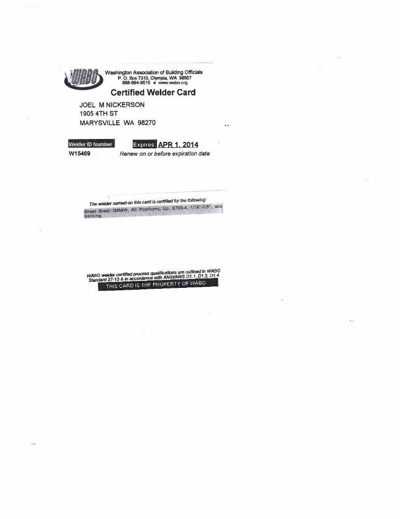
B.) Joel Nickerson Welding Certification
C.) Hilti Powder Actuated Pins
D.) Hilti Screws

This submittal is for Engineers, Architects, Contractors and Professional for the purpose of submitting STEELER INC. products for
review and approval.
Specification and Code:
2006, 2009, and 2012 International Building Code (IBC)
North American Specification for the Design of Cold-formed Steel Structural Members, NASPEC
Gypsum Association Fire Resistance Design Manual
Underwriters Laboratories Inc. -- Fire Resistance Directory
ICC-ES ESR-2054, dated November 1, 2009
ICC-ES ER-4943P, dated September 1, 2001
City of Los Angeles (COLA) Research Report 25529
Material Specifications:
STEELER INC. products are cold-formed shaped manufactured from steel coils meeting ASTM A653/A653M or ASTM
A1003/A1003M Specifications from Grade 33 to Grade 57 with material thicknesses from 18 mils (0.0179 inches) to 118 mils (0.1180
inches). For material strength, members shall be marked legibly in the web identifying the material yield strength.
Corrosion Protection:
STEELER INC. products have protective coating specified as G40, G60, and G90 coating designations. Material thicknesses from 18 to
30 mils have G40 coating and 33 mils to 118 mils have G60 coatings. G90 coating is a special order and is available for some material
thicknesses. Other coating finishes A40, A60, G40 painted, G60 painted and G40 black paint are available.
Design Specifications:
STEELER INC. products are design in accordance with 2001 NASPEC and 2004 Supplement Specifications, and/or 2007 NASPEC and
2010 Supplement Specifications.
Material Tolerances:
STEELER INC. products comply with manufacturing tolerances listed in ASTM C955 for structural members and ASTM C645 for
non-structural framing members.
Product Identification:
STEELER INC. products are identified with legible stamps spaced at a maximum of 24 inches on center located on the web of the
framing member in accordance with ASTM C654, C955, A1003, and AISI S102-07 Specifications.
Product Part Number:
STEELER INC. product part number system has adopted the standard designator system for identifying cold-formed steel framing
members. See STEELER Part Number Specifications for more information.
Punch-outs:
STEELER INC. products have web punch-out as shown in Figure 1 of ICC-ES ESR-2054 Report. Punch-outs are not available for
member with 97 mils and thicker unless specially ordered.
Mill Test Certificate:
STEELER INC. products upon request will supply Mill Test Certificates.
S_NS– 3/5/2012 Steeler, Inc.
Specification and Code Information
Product Submittal Sheet Corporate Sales
P 800.275.2279
Engineering Services
P 206.760.7100

Steeler products are in accordance with the following referenced documents:
AISI S100-07, North American Specification for the Design of Cold-Formed Steel Structural Members, American Iron and
Steel Institute, Washington DC.
AISI S201-07, North American Standard for Col-formed Steel Framing – Product Data, American Iron and Steel Institute,
Washington DC.
ASTM A1003/A1003M, Standard Specification for Sheet Steel, Carbon, Metallic and Non-Metallic Coated for Cold-formed
Framing Members, ASTM International, West Conshohocken, PA.
ASTM C645, Standard Specification for Nonstructural Steel Framing Members, ASTM International, West Conshohock-
en, PA.
ASTM C754, Standard Specification for Installation of Steel Framing Members to Receive Screw-Attached Gypsum Panel
Products, ASTM International, West Conshohocken, PA.
ASTM C954, Standard Specification for Steel Drill Screws for the Application of Gypsum Panel Products or Metal Plaster
Bases to Steel Studs From 0.033 in. to 0.112 in in Thickness, ASTM International, West Conshohocken, PA.
ASTM C955, Standard Specification for Load-Bearing (Transverse and Axial) Steel Studs, Runners (Tracks), and Bracing or
Bridging for Screw Application of Gypsum Panel Products and Metal Plaster Bases, ASTM International, West Con-
shohocken, PA.
ASTM C1002, Steel Self-Piercing Tapping Screws for the Application of Gypsum Panel Products or Metal Plaster Bases to
Wood Studs or Steel Studs, ASTM International, West Conshohocken, PA.
ASTM, C1513, Standard Specification for Steel Tapping Screws for Cold-Formed Steel Framing Connections, ASTM Interna-
tional, West Conshohocken, PA.
AWS, D1.3, Structural Welding Code-Sheet Steel, 1998 Edition, American Welding Society, Miami, FL.
CAN/CSA-S136, North American Specification for the Design of Cold-Formed Steel Structural Members, Canadian Stand-
ards Association, Mississauga, Ontario, Canada.
ASTM A653/A653M, Standard Specification for Steel Sheet Zinc-coated (Galvanized) or Zinc-Iron Allow Coated
(Galvannealed) by the Hot-Kip Process, ASTM International, West Conshohocken, PA.
ASTM A792/A792M, Standard Specification for Steel Sheet, 55% Aluminum-Zinc Allow-Coated by the Hot-Dip Process,
ASTM International, West Conshohocken, PA.
S_NS– 3/5/2012 Steeler, Inc.
Steeler Technical References
Product Submittal Sheet Corporate Sales
P 800.275.2279
Engineering Services
P 206.760.7100

Form
MFG
- 10
0
R
ev. 1
0
12/0
9/09
Stee
l Par
t Num
ber S
pec.
St
ock
Cod
e Sp
ecifi
catio
n fo
r Ste
eler
Man
ufac
ture
d Pr
oduc
ts
0362
S125
-030
N10
.625
JG4S
Web
Siz
e
Fla
nge
in
T
hick
ness
L
engt
h in
feet
in in
ches
inc
hes
in
mils
10.
625
= 10
’ 7 ½
”
S=St
eele
r
0
362
= 3
5/8”
125
= 1
¼”
H
emm
ing
S
hape
N =
No
Hem
min
g
Pun
ch
S =
Stud
(SS,
CW
, EW
C, H
S, H
WC
& W
C)
H =
Hem
med
N =
Nor
mal
T
= T
rack
(TT
, DL
T &
BT
)
J
= N
o Pu
nch
A =
Ang
le
Col
or C
odes
F =
Furr
ing
Cha
nnel
(DW
C &
DW
CX
)
mil
Col
or
Fin
ish
H
= S
haft
Wal
l Stu
d (S
WS)
18
C
lear
G
4 =
G40
Gal
vani
zatio
n
J
= J
Tra
ck (J
T)
2
4
Bro
wn
G6
= G
60 G
alva
niza
tion
L =
Slip
Tra
ck (S
T)
2
7
Bla
ck
G9
= G
90 G
alva
niza
tion
N =
Slo
tted
Stu
d (N
S)
30
P
ink
A
4 =
A40
Gal
vane
aled
R
= S
ound
Res
ilien
t Cha
nnel
(SR
C)
33
W
hite
A
6 =
A60
Gal
vane
aled
U
= C
old
Rol
led
Cha
nnel
(CR
C)
43
Y
ello
w
P4
= G
40 P
aint
ed S
teel
Z
= Z
Fur
ring
(ZF)
5
4
Gre
en
P6
= G
60 P
aint
ed S
teel
D
= D
efle
ctio
n T
rack
(DFT
)
68
O
rang
e
B
P =
G40
Bla
ck P
aint
P
= Po
ny W
all S
tuds
(PW
S)
9
7
Red
C
= Sl
otte
d T
rack
(CC
)
118
Blu
e
I =
Stee
ler
Floo
r Jo
ist
*
B =
Bra
ke S
hape
(BS)
*
K =
Fla
t Sto
ck (F
S)
* S
hape
s not
pre
sent
ly im
plem
ente
d –
use
exis
ting
part
num
bers

Description
Materials
ASTM & Code Standards
Color Code
Studs are fabricated from 20 to 10 gauge hot dipped galvanized steel.
Designated minimum steel thicknesses range from 33 mils – 118 mils and
are made from steel coils conforming to ASTM A653 SS Grade 33, Grade
50, Class 1, or Grade 55 Mod 57, with a minimum G60 galvanized coat-
ing (other coatings are also available), ASTM A1003 Grade 33 Type H
(ST33H), Grade 50 Type H (ST50H), or Grade 57.
Traditional
20S Gauge — White
18 Gauge — Yellow
16 Gauge — Green
14 Gauge — Orange
12 Gauge — Red
10 Gauge— Blue
Elite
33ES Gauge — Purple
43ES Gauge — Brown
54ES Gauge — Light Blue
IBC 2009/2012
AISI NASPEC 2007
Meets or exceeds:
ASTM C754 & ASTM C955
ASTM E119 & E90
ASTM A370
ASTM A1003
ASTM C1513
S_NS– 3/5/2012 Steeler, Inc.
Please reference Steeler ICC-ES
Report ESR-2054 for further infor-
mation. Available for download at
www.steeler.com/technicalinfo.php
Stud (Structural S-Member)
Product Submittal Sheet Corporate Sales
P 800.275.2279
Engineering Services
P 206.760.7100
Seattle Plant | 10023 MLK Jr. Way S. Seattle, WA 98178 | P: 206-725-2500
Newark Plant | 6851 Smith Ave. Newark, CA 94560 | P: 510-505-9574
Manufacturer Contact Information
Traditional
Member Gauge
Design
Thickness
(in.)
Minimum
Thickness
(in.)
20S 0.0346 0.0329
18 0.0451 0.0428
16 0.0566 0.0538
14 0.0713 0.0677
12 0.1017 0.0966
10 0.1242 0.118
Elite
Member Gauge
Design
Thickness
(in.)
Minimum
Thickness
(in.)
33ES 0.0295 0.0223
43ES 0.0400 0.0380
54ES 0.0505 0.0480
Steeler Structural Studs are S-members (C-sections) used as load-
bearing and nonload-bearing studs and joists, and are available in
depths (webs) ranging from 1.625” – 16”, and in widths (flanges) ranging
from 1.25” – 3.5”.
Notes:
1. All thicknesses are uncoated base metal thickness.
2. Minimum thickness equals 95% design thickness.

Description Steeler CFS T-Members are used as tracks in load-bearing and nonload-
bearing walls in
light-framed steel construction, and are available in depths (webs) rang-
ing from 1.625”– 16” to match available S-members, and in widths (legs)
of 1”, 1.25”, 1.5” 2”, 2.5” and 3”.
Materials Track section is fabricated from hot dipped galvanized steel conforming
to ASTM A653 SS Grade 33, Grade 50, Class 1, or Grade 55 Mod 57.
Designated minimum steel thicknesses range from 18 mils – 118 mils and
are made from steel coils conforming to the same ASTM standards and
grades as corresponding studs, with a minimum G40 galvanized coating
for 18-30 mil, and a minimum G60 galvanized coating for 33-118 mil
(other coatings also available).
Color Code Traditional
25 Gauge — Clear (No Paint)
24 Gauge — Orange
22 Gauge — Black
20D Gauge— Pink
20S Gauge — White
18 Gauge — Yellow
16 Gauge — Green
14 Gauge — Orange
12 Gauge — Red
10 Gauge — Blue
Elite
25TI Gauge — Clear/White Stripe
20TI Gauge — Clear/Red Stripe
30ED Gauge — Red and Blue
33ES Gauge — Purple
43ES Gauge — Brown
54ES Gauge — Light Blue
S_NS– 3/5/2012 Steeler, Inc.
ASTM & Code Standards
IBC 2009/2012
AISI NASPEC 2007
Meets or exceeds:
ASTM C955 & ASTM C645
ASTM E119 & E90
ASTM A370
ASTM A1003
ASTM C754 & C1513
Please reference Steeler ICC-ES
Report ESR-2054 for further infor-
mation. Available for download at
www.steeler.com/technicalinfo.php
Track
Product Submittal Sheet Corporate Sales
P 800.275.2279
Engineering Services
P 206.760.7100
Seattle Plant | 10023 MLK Jr. Way S. Seattle, WA 98178 | P: 206-725-2500
Newark Plant | 6851 Smith Ave. Newark, CA 94560 | P: 510-505-9574
Manufacturer Contact Information
Traditional
Member
Gauge
Design
Thickness
(in.)
Minimum
Thickness
(in.)
25 0.0188 0.0179
24 0.0247 0.0235
22 0.0283 0.0269
20D 0.0312 0.0296
20S 0.0346 0.0329
18 0.0451 0.0428
16 0.0566 0.0538
14 0.0713 0.0677
12 0.1017 0.0966
10 0.1242 0.118
Elite
Member
Gauge
Design
Thickness
(in.)
Minimum
Thickness
(in.)
25TI 0.0166 0.0158
20TI 0.0188 0.0179
30ED 0.0235 0.0223
33ES 0.0295 0.0280
43ES 0.0400 0.0380
54ES 0.0505 0.0480
Steeler LEED® Information
LEED Credit MR 2: Steeler framing products are manufactured
from cold-formed steel (CFS). CFS is 100% recyclable and
therefore contributes significantly to LEED Credit MR 2. The
specific contribution amounts will vary depending on the
project and construction decisions.
LEED Credit MR 4: Steeler framing products contain a
minimum of 26% post-consumer and 7% pre-consumer recycled
steel content for a minimum of 33% recyclable. Recycled content
of materials contributes to LEED Credits MR 4. If notified in
advance, Steeler can order steel containing higher percentages
of recycled content to meet your specific project needs. Contact
Steeler technical services prior to ordering so we can help
support your project goals.

Description Angles are available with flanges of 1", 1-1/2", 2", and other flanges are
available for special
order up to 12". Standard lengths are 10'.
Hemmed Angle is available in 25 gauge and 25TI gauge and lengths
from 3" to 20'. Hemmed angle is available with flanges of 1", 1 -1/4", 1 -
1/2", 2", and 2 -1/2". Both flanges must be the same size.
Materials ANGLE sections are fabricated from hot dipped galvanized steel con-
forming to ASTM A653 Grades 33, 50 and 57.
ASTM & Code Standards
Color Code Traditional
25 Gauge — Clear (No Paint)
24 Gauge — Orange
22 Gauge — Black
20D Gauge — Pink
20S Gauge — White
18 Gauge — Yellow
16 Gauge — Green
14 Gauge — Orange
12 Gauge — Red
10 Gauge — Blue
Elite
25TI Gauge — Clear/White Stripe
20TI Gauge — Clear/Red Stripe
30ED Gauge — Red and Blue
33ES Gauge — Purple
43ES Gauge — Brown
54ES Gauge — Light Blue
IBC 2009/2012
AISI NASPEC 2007
Meets or exceeds:
ASTM C955 & ASTM C645
ASTM E119 & E90
ASTM A370
ASTM A1003
ASTM C1513 & C754
S_NS– 3/5/2012 Steeler, Inc.
Please reference Steeler ICC-ES
Report ESR-2054 for further infor-
mation. Available for download at
www.steeler.com/technicalinfo.php
Angle and Hemmed Angle
Product Submittal Sheet Corporate Sales
P 800.275.2279
Engineering Services
P 206.760.7100
Seattle Plant | 10023 MLK Jr. Way S. Seattle, WA 98178 | P: 206-725-2500
Newark Plant | 6851 Smith Ave. Newark, CA 94560 | P: 510-505-9574
Manufacturer Contact Information
Angle
Steeler Angle Part # Description
0100A100 1" x 1" Angle
0150A150 1 1/2" x 1 1/2" Angle
0200A200 2" x 2" Angle
Hemmed Angle
Steeler Hemmed Angle Part # Description
0125A125-018H or 25TIH 1 1/4" x 1 1/4" Hemmed Angle, 25 Gauge or 25TI Gauge
0150A150-018H 1 1/2" x 1 1/2" Hemmed Angle, 25 Gauge or 25TI Gauge
0200A200-018H 2" x 2" Hemmed Angle, 25 Gauge or 25TI Gauge
0250A250-018H 2 1/2" x 2 1/2" Hemmed Angle, 25 Gauge or 25TI Gauge
Steeler LEED® Information
LEED Credit MR 2: Steeler framing products are
manufactured from cold-formed steel (CFS). CFS is
100% recyclable and therefore contributes significantly
to LEED Credit MR 2. The specific contribution amounts
will vary depending on the project and construction
decisions.
LEED Credit MR 4: Steeler framing products contain a
minimum of 26% post-consumer and 7% pre-consumer
recycled steel content for a minimum of 33% recyclable.
Recycled content of materials contributes to LEED
Credits MR 4. If notified in advance, Steeler can order
steel containing higher percentages of recycled content
to meet your specific project needs. Contact Steeler
technical services prior to ordering so we can help
support your project goals.

Description CRC’s (Cold Rolled Channels) are fabricated in 3/4”, 1 1/2”, 2” and 2 1/2”
widths, from 18 and 16 (50ksi) gauge steel. The Flange size is 1/2”.
Length - 10’-0” and 20’-0”. Special lengths are available.
Materials CRC (Cold Rolled Channel) section is fabricated from 18 and 16 (50ksi)
gauge hot dipped galvanized steel conforming to ASTM A653 or equal.
Color Code
Traditional
18 Gauge — Yellow
16 Gauge — Green
S_NS– 3/5/2012 Steeler, Inc.
ASTM & Code Standards
IBC 2009/2012
AISI NASPEC 2007
Meets or exceeds:
ASTM C754 & ASTM 955
ASTM E119 & E90
ASTM A370
ASTM A1003
Please reference Steeler ICC-ES
Report ESR-2054 for further infor-
mation. Available for download at
www.steeler.com/technicalinfo.php
Cold-Rolled Channel (CRC)
Product Submittal Sheet Corporate Sales
P 800.275.2279
Engineering Services
P 206.760.7100
Seattle Plant | 10023 MLK Jr. Way S. Seattle, WA 98178 | P: 206-725-2500
Newark Plant | 6851 Smith Ave. Newark, CA 94560 | P: 510-505-9574
Manufacturer Contact Information
Steeler LEED® Information LEED Credit MR 2: Steeler framing products are manufactured from
cold-formed steel (CFS). CFS is 100% recyclable and therefore contributes
significantly to LEED Credit MR 2. The specific contribution amounts will
vary depending on the project and construction decisions.
LEED Credit MR 4: Steeler framing products contain a minimum of 26%
post-consumer and 7% pre-consumer recycled steel content for a
minimum of 33% recyclable. Recycled content of materials contributes to
LEED Credits MR 4. If notified in advance, Steeler can order steel
containing higher percentages of recycled content to meet your specific
project needs. Contact Steeler technical services prior to ordering so we
can help support your project goals.
Table 3-U-Member (Cold-Rolled Channel) Section Properties; Traditional Thickness Members
Member ID Des-
ignation
Dimensions
in
Full Properties Torsional 33 ksi Effective Properties 50 ksi Effective Properties
Area
in2
Wt.
lb/ft
Ix
in4
rx
in
Iy
in4
ry
in
J
10-3 in4
Cw
in6
rO
in
Xo
In
Ma
k-in
Ixe
in4
Sxe
in3
Ae
in2
Ma
k-in
Ixe
in4
Sxe
in3
Ae
in3 A B
075 U050-030 0.75 0.50 0.0501 0.1705 0.0045 0.3004 0.0013 0.160 0.0163 0.00010 0.4869 -0.3481 0.250 0.0045 0.0121 0.0501
075 U050-033 0.75 0.50 0.0554 0.1883 0.0050 0.2991 0.0014 0.160 0.0221 0.00011 0.4852 -0.3470 0.295 0.0050 0.0132 0.0554
075 U050-043 0.75 0.50 0.0712 0.2422 0.0062 0.2949 0.0018 0.158 0.0483 0.00014 0.4797 -0.3437 0.378 0.0062 0.0165 0.0712
075 U050-054 0.75 0.50 0.0871 0.2963 0.0073 0.2893 0.0021 0.156 0.0931 0.00015 0.4743 -0.3418 0.459 0.0073 0.0195 0.0871 0.680 0.0073 0.0195 0.0871
150 U050-030 1.50 0.50 0.0735 0.2500 0.0231 0.5609 0.0016 0.149 0.0239 0.00058 0.6393 -0.2680 0.625 0.0231 0.0309 0.0720
150 U050-033 1.50 0.50 0.0813 0.2765 0.0255 0.5596 0.0018 0.149 0.0325 0.00064 0.6375 -0.2670 0.758 0.0255 0.0340 0.0813
150 U050-043 1.50 0.50 0.1051 0.3572 0.0324 0.5553 0.0023 0.147 0.0712 0.00079 0.6320 -0.2637 0.989 0.0324 0.0432 0.1051
150 U050-054 1.50 0.50 0.1296 0.4406 0.0390 0.5489 0.0027 0.146 0.1384 0.00091 0.6254 -0.2620 1.230 0.0390 0.0521 0.1296 1.821 0.0390 0.0521 0.1296
200 U050-030 2.00 0.50 0.0891 0.3031 0.0466 0.7233 0.0018 0.141 0.0289 0.00118 0.7728 -0.2331 0.940 0.0466 0.0466 0.0768
200 U050-033 2.00 0.50 0.0986 0.3353 0.0514 0.7219 0.0019 0.140 0.0394 0.00129 0.7711 -0.2321 1.148 0.0514 0.0514 0.0886
200 U050-043 2.00 0.50 0.1276 0.4339 0.0657 0.7175 0.0025 0.139 0.0865 0.00161 0.7658 -0.2289 1.504 0.0657 0.0657 0.1266
200 U050-054 2.00 0.50 0.1579 0.5368 0.0797 0.7106 0.0030 0.137 0.1686 0.00189 0.7585 -0.2272 1.883 0.0797 0.0797 0.1579 2.789 0.0797 0.0797 0.1579
250 U050-030 2.50 0.50 0.1047 0.3561 0.0813 0.8809 0.0019 0.133 0.0340 0.00203 0.9145 -0.2065 1.307 0.0813 0.0650 0.0794
250 U050-033 2.50 0.50 0.1159 0.3941 0.0897 0.8794 0.0020 0.133 0.0463 0.00222 0.9128 -0.2055 1.602 0.0897 0.0717 0.0922
250 U050-043 2.50 0.50 0.1502 0.5105 0.1149 0.8749 0.0026 0.131 0.1018 0.00278 0.9075 -0.2026 2.106 0.1149 0.0919 0.1348
250 U050-054 2.50 0.50 0.1862 0.6331 0.1401 0.8675 0.0031 0.130 0.1988 0.00328 0.8999 -0.2008 2.648 0.1401 0.1121 0.1847 3.921 0.1401 0.1121 0.1703
For SI: 1 inch = 25.4 mm, 1 in2 = 645 mm2, 1 in3 = 1.64x104 mm, 1 in4 = 4.16x105 mm, 1 in6 = 2.69x108 mm, 1 kip-in = 113.3 N-m, 1 kip = 4.4 kN
For CAD & BIM Drawings, Architectural
Specifications and more, find Steeler on:

POWDER ACTUATED PIN SUBMITTAL
Includes:
ICC Report ESR-1663MSDS for Boosters

ICC-ES Evaluation Reports are not to be construed as representing aesthetics or any other attributes not specifically addressed, nor are they to be construed as an endorsement of the subject of the report or a recommendation for its use. There is no warranty by ICC Evaluation Service, Inc., express or implied, as to any finding or other matter in this report, or as to any product covered by the report.
Copyright © 2009 Page 1 of 8
ICC-ES Evaluation Report ESR-1663 Issued January 1, 2009 This report is subject to re-examination in one year.
www.icc-es.org | (800) 423-6587 | (562) 699-0543 A Subsidiary of the International Code Council ®
DIVISION: 03—CONCRETE Section: 03151—Concrete Anchoring DIVISION: 05—METALS Section: 05090—Metal Fastenings DIVISION: 06—WOOD AND PLASTICS Section: 06090—Wood and Plastic Fastenings DIVISION: 09—FINISHES Section: 09051—Fasteners REPORT HOLDER: HILTI, INC. 5400 SOUTH 122nd EAST AVENUE TULSA, OKLAHOMA 74146 (800) 879-8000 www.us.hilti.com EVALUATION SUBJECT: HILTI LOW-VELOCITY POWER-DRIVEN FASTENERS 1.0 EVALUATION SCOPE
Compliance with the following codes:
2006 International Building Code® (IBC)
2006 International Residential Code® (IRC)
2003 International Building Code® (2003 IBC)*
2003 International Residential Code® (2003 IRC)*
2000 International Building Code® (2000 IBC)*
2000 International Residential Code® (2000 IRC)*
1997 Uniform Building Code™ (UBC)*
*Codes indicated with an asterisk are addressed in Section 8.0.
Property evaluated:
Structural
2.0 USES
Hilti power-driven fasteners are used to attach wood, light gage steel, and other fixtures to normal-weight and structural sand-lightweight concrete, metal decks with structural sand-lightweight concrete fill, concrete masonry units (CMUs) and steel base materials. The fasteners are alternatives to the cast-in-place anchors described in Sections 1911 and 1912 of the IBC for placement in
concrete; the embedded anchors described in Section 2.1.4 of ACI 530 (which is referenced in IBC Section 2107); and the bolts used to attach materials to steel, described in IBC Section 2204.2. The fasteners may also be used under the IRC where an engineered design is submitted in accordance with IRC Section R301.1.3.
3.0 DESCRIPTION
3.1 Fasteners:
The fasteners are manufactured as nails or threaded studs with various shank diameters, thread diameters, lengths, and smooth or knurled shanks. When the fastener nomenclature includes an “E” (e.g., X-EDNI 16 P8 vs. X-DNI32 P8) the fastener has a knurled shank. The carbon steel fasteners are manufactured from austempered steel conforming to SAE 1060 or 1070 (modified). The carbon steel fasteners are zinc-plated to ASTM B 633, SC 1, Type III. The stainless steel X-CR fasteners are manufactured from a proprietary CrNiMo alloy complying with the requirements of SAE 316. The premounted washers for the X-CR fasteners are manufactured from stainless steel conforming to SAE 316. All fasteners have a Rockwell C 49-61 hardness.
3.2 Normal-weight Concrete:
Normal-weight concrete must be normal-weight, stone-aggregate concrete complying with IBC Section 1905 or IRC Section R402.2, as applicable.
3.3 Structural Lightweight Concrete:
Structural lightweight concrete must be sand-lightweight complying with IBC Section 1905 or IRC Section R402.2, as applicable, and must have a minimum 3,000 psi (19.17 MPa) compressive strength at the time of fastener installation. Where applicable, fasteners must be placed through the metal deck into structural sand-lightweight concrete in accordance with Tables 3 and 4. Steel deck properties and configurations must be as described in Tables 3 and 4 and Figures 1 through 3 of this report.
3.4 Concrete Masonry Units:
Masonry must be comprised of normal-weight concrete masonry units (CMUs) complying with ASTM C 90 and Type N mortar complying with IBC Section 2103.8 or IRC Section R607, as applicable. Where specified in Table 5 of this report, concrete-masonry construction must be fully grouted and have minimum prism strength, f′m, of 1,500 psi (10.3 MPa) at the time of fastener installation. Grout must comply with Section 2103.12 of the IBC or Section R609.1.1 of the IRC, as applicable.

ESR-1663 | Most Widely Accepted and Trusted Page 2 of 8
3.5 Steel Substrates: Structural steel supports must comply with requirements in the applicable code, with a minimum tensile strength of 58 or 65 ksi (400 or 450 MPa) as noted in Table 1 of this report, and a minimum thickness of 1/8 inch (3.2 mm).
4.0 DESIGN AND INSTALLATION 4.1 Design: The allowable tension and shear loads, along with fastener descriptions and shank diameters for power-driven fasteners installed in carbon steel base materials, are shown in Table 1. The allowable tension and shear loads with minimum required embedment depths, along with fastener descriptions and shank diameters for fasteners in normal-weight and structural sand-lightweight concrete base materials, are shown in Tables 2, 3, and 4. The allowable tension and shear loads with minimum required embedment depths, along with fastener descriptions and shank diameters, for fasteners in concrete masonry units (CMUs), are shown in Table 5.
Allowable loads for fasteners subjected to combined shear and tension forces are determined by the following formula:
(Ps/Pt) + (Vs/Vt) ≤ 1
where:
Ps = Applied service tension load, pounds (N).
Pt = Service tension load, pounds (N).
Vs = Applied service shear load, pounds (N).
Vt = Service shear load, pounds (N).
4.2 Wood to Steel, Concrete, or Masonry: Allowable lateral and withdrawal design loads for fasteners determined in accordance with Part 11 of ANSI/AF&PA NDS and presented in the referenced tables, are applicable to Hilti fasteners of equal or greater diameters. The wood element is the side member. The fastener bending yield strength must be the value noted in the NDS based on the fastener diameter.
4.3 Installation: Fastener placement requires a low-velocity powder-actuated tool used in accordance with Hilti’s published installation procedures. Additional installation requirements are set forth in Tables 1 to 5 of this report. When installation is in steel, minimum spacing between fasteners must be 1 inch (25.4 mm) on center, and minimum edge distance must be 1/2 inch (12.7 mm). Unless otherwise noted, when installation is in concrete, minimum spacing between fasteners must be 4 inches (102 mm) on center and minimum edge distance must be 3 inches (76 mm). Unless otherwise noted, concrete thickness must be a minimum of three times the embedment depth of the fastener. For CMUs, no more than one power-driven fastener may be installed per individual CMU cell.
The DX Kwik system, described in Table 2, requires that a 0.709-inch-deep (18 mm) hole with a diameter of 0.197 inch (5 mm) be drilled into the concrete prior to the placement of the fastener. The fastener must be driven into the predrilled hole and must penetrate the concrete beyond the bottom of the hole.
5.0 CONDITIONS OF USE
The Hilti Low-Velocity Power-Driven Fasteners described in this report comply with, or are suitable alternatives to what is specified in, those codes listed in Section 1.0 of this report, subject to the following conditions:
5.1 Fasteners must be manufactured and identified in accordance with this report.
5.2 Fasteners must be installed in accordance with this report and instructions published by Hilti, Inc. In the event of conflict between this report and Hilti, Inc., published instructions, this report governs.
5.3 Allowable loads must be in accordance with Section 4.1. Calculations proving that the applied loads are less than the maximum allowable loads described in this report must be submitted to the code official for approval. The calculations must be prepared by a registered design professional where required by the statutes of the jurisdiction in which the project is constructed.
5.4 The use of fasteners to resist earthquake loads is outside the scope of this report except for fasteners used with architectural, electrical and mechanical components as described in Section 13.1.4 of ASCE/SEI 7.
5.5 The allowable loads in Tables 2, 3, 4, and 5 are limited to installations in uncracked concrete or masonry. Cracking occurs when ft > fr due to service loads or deformations.
5.6 Hilti X-CR stainless steel fasteners are permitted for use in exterior, damp environments. All other fasteners in this report are limited to installation in dry, interior environments.
5.7 Hilti X-CR stainless steel fasteners may be installed in contact with preservative-treated or fire-retardant-treated wood, as set forth in the applicable code. Use of other fasteners in contact with preservative-treated or fire-retardant-treated wood is outside the scope of this report.
6.0 EVIDENCE SUBMITTED Data in accordance with the ICC-ES Acceptance Criteria for Fasteners Power-driven in Concrete, Steel, and Masonry Elements (AC70), dated October 2006.
7.0 IDENTIFICATION All fasteners are identified by an “H” imprinted on the fastener head. Where applicable, the word “Hilti” is stamped on the steel washers. All fasteners are packaged in containers noting the fastener type, size, manufacturer’s name, and evaluation report number (ESR-1663).
8.0 OTHER CODES
8.1 Evaluation Scope: In addition to the 2006 IBC and 2006 IRC referenced in Section 1.0, the products described in this report were evaluated for compliance with the requirements of the following codes:
2003 International Building Code® (2003 IBC)
2003 International Residential Code® (2003 IRC)
2000 International Building Code® (2000 IBC)
2000 International Residential Code® (2000 IRC)
1997 Uniform Building Code™ (UBC)
8.2 Uses: Hilti power-driven fasteners are used to connect materials as described in Section 2.0. The fasteners are alternatives to the cast-in-place anchors described in 2003 and 2000 IBC Sections 1912 and 1913 and UBC Section 1923.1 for placement in concrete; the embedded anchors described in Section 2.1 of ACI 530 (which is referenced in 2003 and
ESR-1663 | Most Widely Accepted and Trusted Page 3 of 8
2000 IBC Section 2107) and UBC Section 2107.1.5 for placement in grouted masonry; and the bolts used to attach materials to steel, described in 2003 IBC Section 2204.2, 2000 IBC Section 2209, and UBC Section 2205.11. The fasteners may be used where an engineered design is submitted in accordance with 2003 IRC Section R301.1.3 or 2000 IRC Section R301.1.2, as applicable.
8.3 Description:
8.3.1 Fasteners: See Section 3.1.
8.3.2 Concrete: See Sections 3.2 and 3.3. Under the UBC, concrete must conform to Section 1903.
8.3.3 Concrete Masonry Units: See Section 3.4. Under the 2003 and 2000 IBC, mortar and grout must comply with Sections 2103.7 and 2103.10, respectively. Under the UBC, mortar and grout must comply with Sections 2103.3 and 2104.3, respectively.
8.3.4 Steel Substrates: See Section 3.5.
8.4 Design and Installation:
8.4.1 Design: See Section 4.1. The stress increases described in Section 1612.3.2 of the UBC are not allowed for wind loads acting alone or when combined with gravity loads. Except for fasteners used with architectural, electrical and mechanical components as described in
Section 9.6.1 of ASCE/SEI 7-02 (2003 IBC and IRC) or Section 9.6.1 of ASCE/SEI 7-98 (2000 IBC and IRC), use of fasteners to resist earthquake loads is outside the scope of this report.
8.4.2 Wood to Steel, Concrete, or Masonry: See Section 4.2. Reference lateral design values for fasteners determined in accordance with Part 11 of ANSI/AF&PA NDS (2003 IBC and IRC), Part 12 of ANSI/AF&PA NDS (2000 IBC and IRC), or Section 2318.3 of the UBC, as applicable, are applicable to Hilti fasteners of equal or greater diameters.
8.4.3 Installation: See Section 4.3.
8.5 Conditions Of Use: See Section 5.0 and the following: Use of fasteners to resist earthquake loads is outside the scope of this report, except for fasteners used with architectural, electrical and mechanical components as described in Section 9.6.1 of ASCE/SEI 7-02 (2003 IBC and IRC) or Section 9.6.1 of ASCE/SEI 7-98 (2000 IBC and IRC).
8.5 Evidence Submitted: See Section 6.0.
8.6 Identification: See Section 7.0.

ESR-1663 | Most Widely Accepted and Trusted Page 4 of 8
TABLE 1—ALLOWABLE SERVICE LOADS FOR LOW-VELOCITY FASTENERS DRIVEN INTO STEEL1,2,8 (pounds)
STEEL THICKNESS (inch) 1/8 3/16 1/4 3/8 1/2 3/4
FASTENER DESCRIPTION
FASTENER SHANK DIAMETER
(inch) Tension6 Shear6 Tension Shear Tension Shear Tension Shear Tension Shear Tension Shear
Universal Knurled Shank X-EDNI9 0.145 95 235 210 525 675 575 720 605 5803 6353 2603 3503
0.145 140 270 – – – – – – – – – –
0.158 – – 230 665 430 690 – – – – – – Heavy Duty Smooth Shank X-AL-H4
0.177 – – – – – – 595 725 595 860 1505 6005
Heavy Duty Knurled Shank EDS 0.177 – – 305 615 625 870 715 870 890 960 – –
Heavy Duty Smooth Shank
DS 0.177 – – 365 725 580 725 695 725 735 860 – –
Stainless Steel Smooth Shank X-CR 0.145 – – 460 460 615 500 – – – – – –
Stainless Steel Smooth Shank X-CR4 0.145 300 190 615 495 760 500 220 325 225 335 – –
Stepped—Shank Knurling—Lengthwise
X-DAK 0.145 160 370 180 370 230 370 420 470 3657 5007 3657 5007
For SI: 1 inch = 25.4 mm, 1 lbf = 4.48 N, 1 ksl = 6.89 MPa. 1 The tabulated allowable load values utilize a factor of safety that is greater than or equal to 5, calculated in accordance with AC70. Wood or
steel members connected to the substrate must be investigated for compliance with the applicable code in accordance with referenced design criteria.
2 Fasteners must be driven to where the point of the fastener penetrates through the steel base material, except as noted in this report. 3 X-EDNI fasteners installed into 1/2-inch-thick steel require a 9/16-inch minimum penetration. X-EDNI fasteners installed into 3/4-inch or thicker
steel require 7/16-inch minimum penetration. 4 For X-AL-H and noted X-CR fasteners, the steel base material must have a minimum yield strength (Fy) of 50 ksi and minimum tensile
strength of 65 ksi. X-AL-H fasteners with a shank length of 5/8 inch have a shank diameter of 0.145 inch. X-AL-H fasteners with shank lengths of 3/4 inch and 7/8 inch have shank diameters of 0.158 inch. X-AL-H fasteners with shank lengths greater than or equal to 1 inch have a shank diameter of 0.177 inch.
5 X-AL-H fasteners installed into 3/4-inch or thicker steel require 1/2-inch minimum penetration. 6 Except for the X-EDNI fasteners, 1/8-inch-thick steel must have a minimum yield strength of 50 ksi and a minimum tensile strength of 65 ksi. 7 X-DAK fasteners installed into1/2-inch or thicker steel require 3/8-inch, minimum penetration. The allowable tension and shear values for 3/4-
inch or thicker steel apply where the base material has a minimum yield strength of 50 ksi. 8 Except as noted, all allowable load capacities above are based on base steel with minimum yield strength (Fy) of 36 ksi and minimum
tensile strength of 58 ksi. 9 X-EDNI fasteners installed into 1/8-inch-thick ASTM A 569 steel with a minimum yield strength of 50.8 ksi.

ESR-1663 | Most Widely Accepted and Trusted Page 5 of 8
TABLE 2—ALLOWABLE SERVICE LOADS FOR LOW-VELOCITY FASTENERS DRIVEN INTO NORMAL-WEIGHT CONCRETE1,2
CONCRETE COMPRESSIVE STRENGTH 2,000 psi 4,000 psi 6,000 psi
FASTENER DESCRIPTION
FASTENER
SHANK DIAMETER
(inch)
EMBEDMENT (inches)
Tension (lbs.)
Shear (lbs.)
Tension (lbs.)
Shear (lbs.)
Tension (lbs.)
Shear (lbs.)
3/4 45 75 60 105 — —
1 85 150 90 200 — —
11/4 130 210 130 290 — — Standard Nail X-C 0.138
11/2 175 260 245 360 — — 3/4 60 105 110 120 — —
1 145 185 160 240 100 125
11/4 160 290 180 250 200 270 Universal Nail X-DNI 0.145
11/2 220 330 320 425 — —
Drywall Track Nail X-C22 P8 TH 0.138 3/4 55 130 90 170 — — 3/4 65 70 90 95 120 125
1 130 190 165 195 — —
11/4 135 265 240 270 240 440 High Performance
Nail X-AL-H 0.177
11/2 240 340 240 460 — —
High Performance Nail X-AL-H3 0.177 11/2 355 470 475 565 — —
3/4 50 120 125 135 — —
1 130 195 155 240 — —
11/4 220 385 270 425 — — Heavy Duty Nail DS 0.177
11/2 300 405 355 450 — — 3/4 40 55 40 55 — — 1/4-20 Threaded
Stud W6 0.145 1 85 195 110 225 — —
1 85 95 100 105 — —
11/4 175 345 200 380 — — 3/8-16 Threaded
Stud W10 0.205
15/8 285 380 385 395 — —
3/4 30 40 65 40 — —
1 55 185 120 190 100 170
11/4 110 290 125 300 120 440 Stainless Steel
Nail X-CR 0.145
11/2 265 405 350 450 — — For SI: 1 inch = 25.4 mm, 1 psi = 6.8948 kPa, 1 pound = 4.45 N. 1 The tabulated allowable load values utilize a factor of safety that is greater than or equal to 5, calculated in accordance with AC70. Wood or
steel members connected to the substrate must be investigated for compliance with the applicable code in accordance with referenced design criteria.
2 The concrete base material must exhibit the tabulated compressive strength when the fastener is installed. 3 The X-AL-H fastener must be installed using the DX-Kwik drilled pilot hole installation procedure described in Section 4.3.

ESR-1663 | Most Widely Accepted and Trusted Page 6 of 8
TABLE 3—ALLOWABLE SERVICE LOADS FOR LOW-VELOCITY FASTENERS DRIVEN INTO MINIMUM fNc STRUCTURAL SAND-LIGHTWEIGHT CONCRETE1,2
FASTENER LOCATION
Installed into Concrete Installed Through Metal Deck into Concrete3,4
Tension (lb.)
FASTENER DESCRIPTION
FASTENER SHANK DIAMETER
(inch)
MINIMUM EMBEDMENT
(inches)
Tension (lb.)
Shear (lb.) Upper Flute Lower Flute
Shear (lb.)
3/4 110 175 120 - 265
1 135 180 215 145 485 11/4 220 260 250 205 500
Standard Nail X-C 0.138
11/2 285 315 285 210 555 3/4 120 180 - - -
1 175 185 225 115 320 11/4 240 315 365 205 420
Universal Nail X-DNI 0.145
11/2 300 365 480 280 570 X-C20 THP 0.138 5/8 55 110 - 45 285 Drywall Track Nail
X-C22 P8TH 0.138 3/4 110 220 120 60 260 3/4 115 155 - - 155
1 225 350 - 120 340 11/4 330 475 310 195 770
High Performance Nail X-AL-H 0.177
11/2 - - - 285 585 3/4 100 200 - - 200
1 180 360 - 180 405 11/4 300 520 - - 515
Heavy Duty Nail DS5 0.177
11/2 450 680 - 325 625 1 230 240 - - 240
11/4 320 400 - - 400 Stainless Steel
Nail X-CR 0.145
11/2 405 500 - - 500 1 175 185 - - 185
11/4 240 315 - - 315 1/4-20 Threaded
Stud W6 0.145
11/2 300 365 - - 365 1 265 185 - - 185
11/4 280 380 160 210 685 3/8-16 Threaded
Stud W10 0.205
15/8 445 540 435 325 945 For SI: 1 inch = 25.4 mm, 1 psi = 6.8948 kPa, 1 lbf = 4.48 N. 1 The tabulated allowable load values utilize a factor of safety that is greater than or equal to 5, calculated in accordance with AC70. Wood or
steel members connected to the substrate must be investigated in accordance with accepted design criteria. 2 The concrete base material must exhibit the tabulated compressive strength when the fastener is installed. 3 The steel deck profile must be 3-inch-deep composite floor deck, 33 mils thick with a 0.0329-inch base-metal thickness and a minimum yield
strength of 33 ksi. Lower and upper flute width must be a minimum of 41/2 inches. Figure 1 shows the nominal flute dimensions, fastener locations and load orientations for the deck profile.
4 Structural lightweight concrete fill depth above top of metal deck must be a minimum of 31/4 inches. 5 DS fasteners installed at 11/2-inch embedment through steel deck into the lower flute must be installed at a minimum distance of 6 inches
from the edge of the floor deck.

ESR-1663 | Most Widely Accepted and Trusted Page 7 of 8
TABLE 4—ALLOWABLE SERVICE LOADS FOR LOW-VELOCITY FASTENERS DRIVEN INTO MINIMUM fNc = 3,000 psi STRUCTURAL LIGHTWEIGHT CONCRETE OVER 11/2-INCH-DEEP, B-TYPE STEEL DECK (pounds)1,2
FASTENER LOCATION
Installed Through Metal Deck Into Concrete3,4
Tension (lbs.)
FASTENER DESCRIPTION FASTENER SHANK DIAMETER
(inch)
EMBEDMENT (inch)
Upper Flute Lower Flute
Shear (lbs.)
Drywall track nail X-C22 P8 TH 0.138 3/4 90 110 295 3/4 80 80 315
Standard nail X-C 0.138 1 205 205 445
For SI: 1 inch = 25.4 mm, 1 psi = 6.8948 kPa, 1 lbf = 4.48 N.
1 The tabulated allowable load values utilize a factor of safety that is greater than or equal to 5, calculated in accordance with AC70. Wood or steel members connected to the substrate must be investigated in accordance with accepted design criteria.
2 The concrete base material must exhibit the tabulated compressive strength when the fastener is installed. 3 Steel deck profiles are 11/2-inch-deep, B-type deck with a thickness of 33 mils (0.0329 inch thick steel) and minimum yield strength of 38 ksi.
Fasteners may be installed through the steel deck into structural lightweight concrete having both normal or inverted deck profile orientations with minimum lower flute widths of 13/4 and 31/2 inches, respectively. Fasteners must be placed at centerline of deck flutes. Figures 2 and 3 describe additional flute dimensions, fastener locations, and load orientations for both deck profiles.
4 Structural lightweight concrete fill above top of metal deck must be a minimum of 21/2 inches.
TABLE 5—ALLOWABLE SERVICE LOADS FOR LOW-VELOCITY FASTENERS DRIVEN INTO CONCRETE MASONRY UNITS1,2,3,4,5,9 (pounds)
HOLLOW CMU GROUT-FILLED CMU
Face Shell6 Mortar Joint Face Shell6 Mortar Joint Top of Grouted Cell8
FASTENER DESCRIPTION
FASTENER SHANK DIAMETER
(inch)
EMBED-MENT (inch)
Tension(lbs)
Shear (lbs)
Tension(lbs)
Shear7
(lbs) Tension
(lbs) Shear (lbs)
Tension (lbs)
Shear (lbs)
Tension(lbs)
Shear8
(lbs)
Standard Nail X-C 0.138 1 40 85 15 50 85 85 45 85 115 175
Universal Nail X-DNI 0.145 1 40 90 35 60 90 130 40 65 — — 1/4-20 Threaded
Stud W6 0.145 1 105 175 80 110 125 175 135 150 — —
For SI: 1 inch = 25.4 mm, 1 lbf = 4.48 N.
1 The tabulated allowable load values utilize a factor of safety of 8 or higher. Wood or steel members connected to the substrate must be investigated in accordance with accepted design criteria.
2 The tabulated allowable load values are for low-velocity fasteners installed in hollow, ungrouted concrete masonry units conforming to the requirements of Section 3.4.
3 The tabulated allowable load values are for low-velocity fasteners installed in concrete masonry units with mortar conforming to ASTM C 270 or UBC Standard 21-15. Mortar must be proportioned in accordance with Table 2103.7 (1) of the IBC, Table R607.1 of the IRC, or Table 21-15-B of the UBC, as Type N.
4 The tabulated allowable load values are for low-velocity fasteners installed in concrete masonry units with grout conforming to ASTM C 476 or UBC Standard 21-19. Grout must be proportioned in accordance with Table 2103.10 of the IBC, Table R609.1.1 of the IRC, or Table 21-B of the UBC, as coarse grout.
5 No more than one low-velocity fastener may be installed in an individual CMU cell. 6 Shear direction must be horizontal (bed joint or t-joint) along the CMU wall plane. 7 Fastener located in center of grouted cell must be installed vertically. 8 Shear load can be in any direction. 9 Fasteners must be installed a minimum of 8 inches from the end of the wall. Multiple fasteners in a bed joint must be spaced a minimum of 8
inches.

ESR-1663 | Most Widely Accepted and Trusted Page 8 of 8
For SI: 1 inch = 25.4 mm, 1 psi = 6.8948 kPa
FIGURE 1—HILTI FASTENER LOCATIONS IN 3-INCH DEEP COMPOSITE FLOOR DECK
For SI: 1 inch = 25.4 mm, 1 psi = 6.8948 kPa
FIGURE 2—HILTI FASTENER LOCATIONS IN 11/2-INCH DEEP COMPOSITE FLOOR DECK, NORMAL DECK PROFILE ORIENTATION
For SI: 1 inch = 25.4 mm, 1 psi = 6.8948 kPa
FIGURE 3—HILTI FASTENER LOCATION IN 11/2-INCH DEEP COMPOSITE FLOOR DECK, INVERTED DECK PROFILE ORIENTATION

ICC-ES Evaluation Reports are not to be construed as representing aesthetics or any other attributes not specifically addressed, nor are they to be construed as an endorsement of the subject of the report or a recommendation for its use. There is no warranty by ICC Evaluation Service, Inc., express or implied, as to any finding or other matter in this report, or as to any product covered by the report.
Copyright © 2009 Page 1 of 1
ICC-ES Evaluation Report ESR-1663 Supplement Issued January 1, 2009 This report is subject to re-examination in one year.
www.icc-es.org | (800) 423-6587 | (562) 699-0543 A Subsidiary of the International Code Council ®
DIVISION: 03—CONCRETE Section: 03151—Concrete Anchoring DIVISION: 05—METALS Section: 05090—Metal Fastenings DIVISION: 06—WOOD AND PLASTICS Section: 06090—Wood and Plastic Fastenings DIVISION: 09—FINISHES Section: 09051—Fasteners REPORT HOLDER: HILTI, INC. 5400 SOUTH 122ND EAST AVENUE TULSA, OKLAHOMA 74146 (800) 879-8000 www.us.hilti.com EVALUATION SUBJECT: HILTI LOW-VELOCITY POWER-DRIVEN FASTENERS 1.0 EVALUATION SCOPE
Compliance with the following codes: 2007 Florida Building Code—Building
2007 Florida Building Code—Residential
Property evaluated: Structural
2.0 PURPOSE OF THIS SUPPLEMENT
This supplement is issued to indicate that the Hilti EDS, DS, X-AL-H, X-C, X-C20 THP, X-C22 P8TH, X-CR, X-DAK, X-DNI, X-EDNI, W6, and W10 power driven fasteners described in Sections 2.0 through 7.0 and in Tables 1 through 5 of the master report comply with the 2007 Florida Building Code—Building, and the 2007 Florida Building Code—Residential, when designed and installed in accordance with the master evaluation report.
Use of the fasteners described in the master evaluation report for compliance with the High Velocity Hurricane Zone Provisions of the 2007 Florida Building Code—Building or of the 2007 Florida Building Code—Residential has not been evaluated, and is outside the scope of this supplement.
For products falling under Florida Rule 9B-72, verification that the report holder’s quality assurance program is audited by a quality assurance entity approved by the Florida Building Commission for the type of inspections being conducted is the responsibility of an approved validation entity (or the code official when the report holder does not possess an approval by the Commission).
This supplement expires concurrently with the master evaluation report issued on January 1, 2009.

®
MSDS No.: 101Revision No.: 018Revision Date: 02/13/03Page: 1 of 2
HILTI ® is a registered trademark of Hilti Corp.
MATERIAL SAFETY DATA SHEET
Product name: Safety Boosters
Description: 22, 25, and 27 caliber blank cartridges for powder actuated fastening tools
Supplier: Hilti, Inc. P.O. Box 21148, Tulsa, OK 74121; phone 1800 879 8000
Emergency # (Chem-Trec.): 1 800 424 9300 (USA, PR, Virgin Islands, Canada); 001 703 527 3887 (other countries)
INGREDIENTS AND EXPOSURE LIMITS
Ingredients: CAS Number: TLV: PEL: STEL:
Nitroglycerin 00055-63-0 0.46 mg/m3 (S) NE 0.1 mg/m3 (S)Nitrocellulose 09004-70-0 NE NE NELead styphnate 15245-44-0 0.05 mg/m3 * 0.05 mg/m3 * NEBarium nitrate 10022-31-8 0.5 mg/m3 0.5 mg/m3 NETetracene 00109-27-3 NE NE NE
Abbreviations / Symbols: * exposure limit for metallic lead. NE = None Established. NA = Not Applicable. (S) indicatesexposure should be controlled for the cutaneous routes including the mucous membranes, eyes, and skin. Airborne exposuresas well as direct contact must be considered.
PHYSICAL DATA
Appearance: Blank brass cartridges. Odor: None.
Vapor Density: (air = 1) Not applicable. Vapor Pressure: Not applicable.
Boiling Point: Not applicable. VOC Content: Not applicable.
Evaporation Rate: Not applicable. Solubility in Water: Not applicable.
Specific Gravity: Not applicable. pH: Not applicable.
FIRE AND EXPLOSION HAZARD DATA
Flash Point: Not applicable. Flammable Limits: Not applicable.
Extinguishing Media: Water.
Special Fire FightingProcedures:
Flood area with water or keep cartridges cool with water spray.
Unusual Fire and ExplosionHazards:
Cartridges can blast if exposed to temperatures > 160ºC. Mass detonation will not occur.
REACTIVITY DATA
Hazardous Polymerization: Will not occur. Stability: Stable.
Incompatibility: Strong acids and oxidizing agents.
Decomposition Products: Oxides of nitrogen, oxides of carbon, acrid fumes and lead oxide.
Conditions to Avoid: Acids, excessive heat, crushing, and electrical currents.
HEALTH HAZARD DATA
Known Hazards: OSHA has established an action level of 0.03 mg/m3 for lead. Exposures that exceedrecommended limits for lead may be possible under certain conditions such as excessivefiring with little air movement and/or firing in small enclosed work areas. Chronic (long-term)overexposure to lead can result in damage to blood-forming, nervous, urinary and reproductivesystems.
Signs and Symptoms ofExposure:
Excessive exposure to gases might cause irritation to the eyes, skin, and respiratory system.Adverse health effects are not expected from acute exposure to fumes and gases; however,adequate ventilation, personal protective equipment, and/or good personal hygiene practicesare essential to keep exposure to a minimum.
Routes of Exposure: Dermal. Inhalation.
Carcinogenicity: Organic lead compounds are not classified by IARC or NTP as carcinogens. Lead styphnate isconverted to metallic lead and lead oxide during combustion. Metallic lead and lead oxidehave not been tested adequately. A study by Goyer and Rhyne (1973) concluded that "there isno evidence that lead produces cancer in man".

MSDS 101, Page 2 of 2
Medical ConditionsAggravated by Exposure:
None anticipated.
EMERGENCY AND FIRST AID PROCEDURES
Eyes: If irritation occurs, flush with plenty of water. Consult a physician if symptoms persist.
Skin: Practice good hygiene; i.e. wash with soap and water after using and before meals.
Inhalation: Move victim to fresh air. Get medical attention if symptoms persist.
Ingestion: Get immediate medical attention.
Other: Seek prompt medical attention if physical injury occurs from pins, rivets, debris, etc. Forbleeding wounds, place a clean cloth or similar absorbent material on the wound and applyfirm pressure. Elevate the wound and transport immediately to a medical facility.
CONTROL MEASURES AND PERSONAL PROTECTIVE EQUIPMENT
Ventilation: General (i.e., natural or mechanically induced fresh air movements that maintain vaporconcentrations below recommended exposure limits).
Eye Protection: Safety glasses with side-shields, as a minimum. Safety goggles recommended.
Skin Protection: Cleaning powder actuated tools can result in some exposure to lead compounds. Clothgloves are recommended, otherwise, wash hands thoroughly when finished and before eatingor smoking.
Respiratory Protection: Not normally required. Where air movement is inadequate to maintain exposure belowrecommended levels, wear a high efficiency particulate respirator.
Other: Hearing protection (muffs or aural inserts) should be worn when firing powder actuated tools
PRECAUTIONS FOR SAFE HANDLING AND USE
Handling and StoringPrecautions:
Store in a cool dry place. Do not crush or drop. Keep away from excessive heat (such asextremely hot surfaces and flames), electrical current, strong acids and oxidizers. NFPA 495requires 15 feet separation (or 1-hour firewall) from flammable liquids, flammable solids, andoxidizers. For industrial use only. Keep out of reach of children. Use with adequateventilation. Practice good hygiene; i.e. wash after using and before eating or smoking.
Other Precautions:: Use only in powder actuated tools designed to handle these boosters. Construction industryemployees must be properly trained as prescribed by OSHA regulations 29 CFR 1926.302 (e).All employees should be familiar with the safe operating procedures and requirements forpowder operated tools as described in ANSI A10.3 and OSHA 29 CFR 1910.243 (d).
REGULATORY INFORMATION
Hazard Communication: This MSDS has been prepared in accordance with the federal OSHA Hazard CommunicationStandard 29 CFR 1910.1200.
HMIS Codes: Health 1, Flammability 1, Reactivity 3, PPE B (Glasses, Gloves)
DOT Shipping Name: Consumer commodity, ORM-D
ICAO / IATA Shipping Name: Cartridges. Power device, Class 1.4S, UN 0323
TSCA Inventory Status: Chemical components listed on TSCA inventory.
SARA Title III, Section 313: This product contains < 1% lead styphnate (CAS No. 15245-44-0), < 0.1% barium nitrate (CASNo. 10022-31-8), and 5 - 11% nitroglycerin (CAS No. 55-63-0) which are subject to thereporting according to Section 313 of the Superfund Amendments and Reauthorization Act of1986 and 40 CFR part 372.
Waste Disposal Methods: Misfires should be stored in a closed container until disposal or as otherwise required bylocal, state, and federal safety, health and environmental regulations. The recommendeddisposal method is in a burner specifically designed to destroy ammunition.
EPA Waste Code(s): D008
CONTACTS
Customer Service: 1 800 879 8000
Technical Service: 1 800 879 8000
Health / Safety: 1 800 879 6000 Jerry Metcalf (x6704)
Emergency # (Chem-Trec): 1 800 424 9300 (USA, PR, Virgin Islands, Canada); 001 703 527 3887 (other countries)
The information and recommendations contained herein are based upon data believed to be correct; however, no guarantee orwarranty of any kind expressed or implied is made with respect to the information provided.

5.1Screw Fastening Systems
Corrosion Resistance for Screws
192 US: 1-800-879-8000 / www.us.hilti.com ❘ Hilti Product Technical Guide 2002 ❘ Canada: 1-800-363-4458 / www.ca.hilti.com
The ability of any fastener to maintain a fastening is directly related to itsability to maintain its embedment in the base material and to avoid loss ofengagement with that material. Any corrosion of the fastener may diminishthis engagement and lessen the performance of the fastener. To help preventthis, a corrosion resistant finish may be applied to the fasteners.
A standard reference to corrosion resistance, the salt spray test is considered a bench mark. The salt spray results given in the following tableare for comparison of the relative corrosion resistance of each coating. Theactual performance of any coating is directly related to the quality of thecoating, the actual environment for the application and the applicationmethod used to install the fastener.
Hilti Screw Fastening Systems Guide to Corrosion Resistance
CARBON STEEL COATED
Salt Spray Anti-CorrosionProtective Coating Composition/Appearance Test Results Properties Comments
Phosphate and Oil Black oil finish 24-48 hours Poor Basic coating for drywall screws(Black Oxide) Good adhesion to drywall plaster
Galvanizing–hot dipped Dull gray–rough 48-144 hours Good Corrosion resistance is dependent upon the thickness of the coatingNot suitable for threaded or internally driven fasteners
Zinc electroplated Silver to gray–bright 24-48 hours Fair Standard for industrial applicationswith Chromate Superior to cadmium in most industrial
atmospheres
Cadmium with Silver/gray–dull to bright 48-144 hours Good Low cost, good appearanceChromate Superior to zinc in salt environments
Zinc/Chromate/Organic Gray, Black or Green 560-800 hours Very Good High performance coating(KwikCote or Equal) Superior to most plated finishes
Nickel/Zinc/Chromate Silver to gray–bright 640-1000 hours Excellent High performance–bright smooth finishresistant to abrasion or damage
HIGHER GRADE STEELS
410 Stainless/ Silver to gray–bright 144-300 hours Good Good appearance–high resistance to Cadmium most corrosive atmospheres
Good choice for structural self-drilling fasteners
300 Series Silver–dull to bright N.A. Excellent Highest corrosion resistance availableStainless Steel Not suitable for self-drilling applications
due to inability to harden beyond RC 32-36
Warning: Because of the potential for delayed hydrogen assisted stress corrosion cracking, many hardened steel fasteners are not recommended foruse with dissimilar metals or chemically treated wood when moisture maybe present or in corrosive environments. For further information, contact Hiltiin the U.S. at 1-800-879-8000 or in Canada, 1-800-363-4458.

5.2Self-Drilling Screw Selection GuideScrew Fastening Systems
193US: 1-800-879-8000 / www.us.hilti.com ❘ Hilti Product Technical Guide 2002 ❘ Canada: 1-800-363-4458 / www.ca.hilti.com
5.2.1 Drill Point Selection
Top Material to be DrilledBottom Material to be Drilled
Top Material to be DrilledVoid or Insulation
Bottom Material to be Drilled
Total Thickness to be Drilled
Hole DiameterLarger than Screw Threads
Top Material Void or Insulation
Bottom Material to be Drilled
Total Thickness to be Drilled
Total Thickness to be Drilled
Drill Flute
The length of the drill flutedetermines the metal thick-ness that can be drilled.Theflute itself provides a channelfor chip removal duringdrilling action. If it becomescompletely embedded in
material, drill chips will be trapped in the flute andcutting action will cease.This will cause the point toburn up or break.
Point Length
The unthreaded section fromthe point to the first threadshould be long enough toassure the drilling action iscomplete before the firstthread engages the drilledmetal. Screw threads
advance at a rate of up to ten times faster than thedrill flute can remove metal. All drilling thereforeshould be complete before threads begin to form.
Drilling Through Wood to Metal
If your application calls fordrilling through wood over1/2" thick, a clearance holeis required. Select a fastenerwith breakaway wings forthis type of job.The wingswill ream a clearance hole
and break-off when they contact metal surface(minimum metal thickness 0.090") to be drilled.
DrillFlute
PointLength Winged
Reamer
Drilling Capacity – MD-Applications (Steel to Steel)
Note: The above chart covers the Hilti standard self-drilling screw program. For information on specialty fasteners (Kwik Seal, wing reamers, etc.),contact your Hilti representative. Shaded area represents optimal drilling range.
1. #12-#4 point winged reamer fasteners have a maximum drill capacity of 0.220".2. 1/4" #4 point winged reamer fasteners have a maximum drill capacity of 0.250".
#5#2 Point #3 Point #4 Point Point
0.500
0.400
0.300
0.200
0.100
0
Screw#8 #10 #10 #12 1/4" #121 1/4"2 #12Diameter
0.035
0.100 0.110
0.175
0.110 0.110 0.110
0.175 0.1750.210
0.250
0.312 0.312
0.250
Thic
knes
s of
mat
eria
l to
be d
rille
d (in
ches
)

5.2Screw Fastening Systems
Self-Drilling Screw Selection Guide
194 US: 1-800-879-8000 / www.us.hilti.com ❘ Hilti Product Technical Guide 2002 ❘ Canada: 1-800-363-4458 / www.ca.hilti.com
5.2.1 Drill Point Selection (Continued)Conversion Tables
Metal Gauge Fraction to Decimal
000000 0.5800 —00000 0.5165 —0000 0.4600 0.4062000 0.4096 0.37500 0.3648 0.34370 0.3249 0.31251 0.2893 0.28122 0.2576 0.26563 0.2294 0.23914 0.2043 0.22425 0.1819 0.20926 0.1620 0.19437 0.1443 0.17938 0.1285 0.16449 0.1144 0.149510 0.1019 0.134511 0.0907 0.119612 0.0808 0.104613 0.0720 0.089714 0.0641 0.074715 0.0571 0.067316 0.0508 0.059817 0.0493 0.053818 0.0403 0.047819 0.0359 0.041820 0.0320 0.035921 0.0285 0.032922 0.0253 0.029923 0.0226 0.026924 0.0201 0.023925 0.0179 0.020926 0.0159 0.017927 0.0142 0.016428 0.0126 0.014929 0.0113 0.013530 0.0100 0.012031 0.0089 0.010532 0.0080 0.009733 0.0071 0.009034 0.0063 0.008235 0.0056 0.007536 0.0050 0.006737 0.0045 0.006438 0.0040 0.0060
(Thickness in decimalparts of an inch)
SheetMetalAluminumNumber
ofGauge
Fraction (in.) DecimalEquivalent (in.)
1/64 0.0151/32 0.0313/64 0.0461/16 0.0625/64 0.0783/32 0.0937/64 0.1091/8 0.1259/64 0.1405/32 0.15611/64 0.1713/16 0.18713/64 0.2037/32 0.21815/64 0.2341/4 0.250
Number of DecimalGauge Equivalent (in.)
#6 0.138#8 0.164#10 0.190#12 0.216#14 0.242
Screw Wire Gauge
Thread Pitch
The thickness of material being fastened and diameter of the screw deter-mine the type of thread pitch to be used. In general, the thinner the fastenedmaterials, the fewer the number of threads. The thicker the material, thegreater the number of threads. This principle is due to two primary methodsof thread engagement/holding power: Clamping and Threading. In lightgauge metal, the materials are actually being clamped together by the upperand lower threads.
Always choose a fastener with sufficient threads to fully engage in the basemetal. For attachments to 1/4" base steel, a self-drilling screw should haveat least 1/4" of threads. It is helpful, but not critical, that the threads alsoengage in the material being fastened. The head of the fastener providesthe bearing force for the material being fastened, while the threads providethe clamping force in the base material.
Thinner base material requires a coarser thread pitch to assure properclamping. The thicker the material, the finer the threads must be. In verythick metal (3/8" - 1/2" thick), a fine thread is advisable. This will allow thethread to tap into the base material with less installation torque than acoarse thread.
Clamping
Material Being Fastened
Base Material
Threading
Clamping
Thread Engagement
5.2.2 Thread Selection
Thread Length

5.2Self-Drilling Screw Selection GuideScrew Fastening Systems
195US: 1-800-879-8000 / www.us.hilti.com ❘ Hilti Product Technical Guide 2002 ❘ Canada: 1-800-363-4458 / www.ca.hilti.com
5.2.3 Head Style Selection
5.2.4 Sealing Criteria
5.2.5 Length Selection
Length of the screw (L) Maximum thickness fastened (MF)
HWH/HHWH
Hex Washer Head/High Hex Washer Head:Washer face provides a bearingsurface for the driving sockets.
PPH
Phillips Pan Head:Conventional head for generalapplications and provides lowprofile fastening.
PFH
Phillips Flat Head:Used primarily in wood tocountersink and seat flushwithout splintering the wood.
PWH
Phillips Wafer Head:Large head provides the bearingsurface necessary to seat flush insoft materials.
The Kwik-Seal sealing screws offer weatherproof fasteningswhere moisture or condensation is a factor. The integratedwasher/head design seals the hole to prevent moisture fromdripping into the fastener threads, reducing corrosive build-up.As added protection against corrosion, all Kwik-Seal sealingscrews come standard with Kwik-Cote coating. The torquecontrol and adjustment of the Kwik-Tapper electric screw-drivers help ensure that the optimal seal is applied.
If you underdrive, the compression ring designresults in a low torque seal.
If you overdrive, the compression ring, outerskirt, and rugged washerprevents spinout and theone-piece head designcompletely eliminates thepossibility of washer inversion.
If you angle-drive, thedesign of the fastener head, outer skirt, and compression ring, alongwith the special washer,still helps provide a positive seal.
Depending on the screwhead, there are two different ways to measure theoverall length of a screw.
HWH/HHWH, PPH screws overall length is measured from the bottom of thecollar under the head to the point of the screw.
PWH, PFH screws overall length is measured from the top of the head to thepoint of the screw.
L MF
L
MF
The maximum thickness fastened for all screws is the length of the threadsreduced by the first three threads (embedment in the base material). See drawings below.
The maximum thickness fastened (MF) describes the maximum thickness of the attachments to be secured to the base material.