transmittal letter, copies of pertinent records … · lacoste c, ronberg gravity -eter which is...
TRANSCRIPT

DEVINE & NYQUISTATTORNEYS AT LAW
«6 HANOVER STREETDAILY MIRROR OFFICE BUILDING
P.O. BOX 1540MANCHESTER, NEW HAMPSHIRE 03105-15*3
LEE C. NYQUISTKEVIN C. DEVINECOREY BELOBROWT. DAVID PLOURDEMERRICK C. WEINSTEINMAUREEN E. RAICHE
TELEPHONE: (603) 668-588STELECOPIER: <«/>) 668-F902
April 4, 1989
Mr. James ZeppieriDepartment of Environmental Services6 Hazen DriveP.O. Box 95Concord, New Hampshire 03301
Re: OK Tool, Inc.
Dear Mr. Zeppieri:
Pursuant to your request, enclosed please find copies of thepertinent records from the file of John Kick regarding hisSeismic Refraction and Gravity Data. If you have any furtherquestions or concerns regarding Mr. Kick's file, please do nothesitate to contact me.
In addition, enclosed please find copies of two mapsindicating the floor plan of the old building taken by the Statethrough eminent domain in 1977. At this time, I am unaware ofany other maps or floor plans that will be of assistance to you.
Please do not hesitate to contact me if you have anyquestions or concerns.
Very truly yours.
o\<r\
Maureen E. Raiche
MER:twaEnclosures

«r•N.
0
K
£
£ -j
o ^u <
? o1
X ^0 t
o
1on0
! ^8
'o
V
JoO
KiO
8
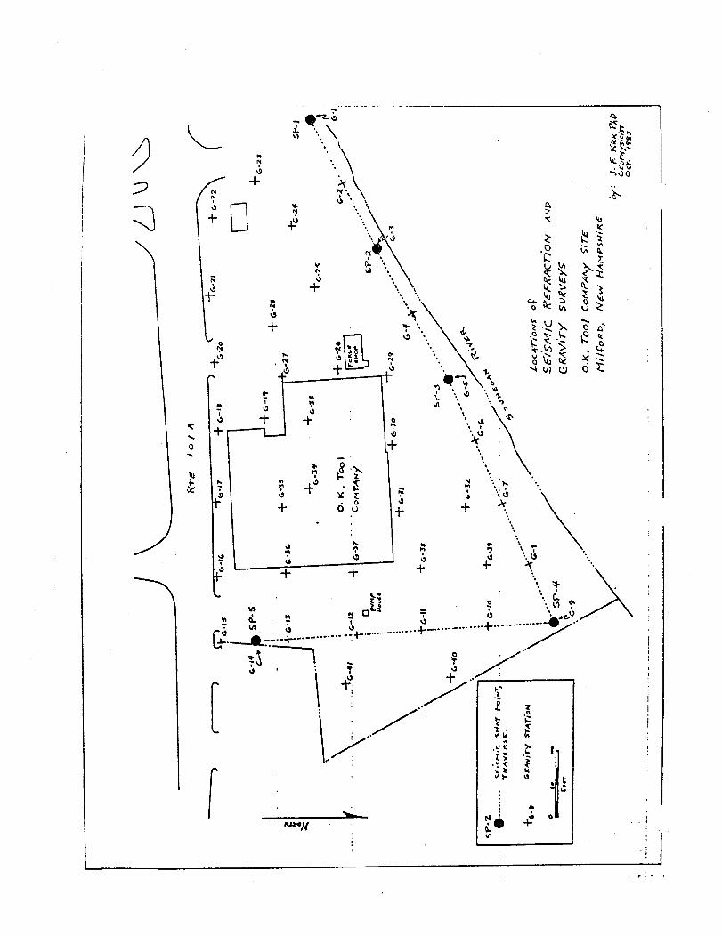
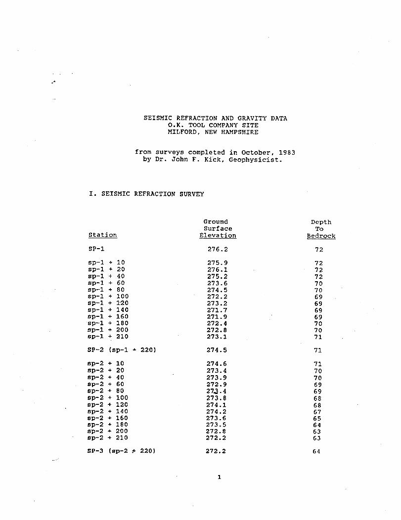
SEISMIC REFRACTION AND GRAVITY DATAO.K. TOOL COMPANY SITEMILFORD, NEW HAMPSHIRE
from surveys completed in October, 1983by Dr. John F. Kick, Geophysicist.
I. SEISMIC REFRACTION SURVEY
Station
SP-1
sp-1sp-1sp-1sp-1sp-1sp-1sp-1sp-1sp-1sp-1sp-1sp-1
SP-2
sp-2sp-2sp-2sp-2sp-2sp-2sp-2sp-2sp-2sp-2sp-2sp-2
* 10+ 20+ 40+ 604 804 100+ 1204 140+ 1604 180-»- 200+ 210
(sp-1 -f 220)
+ 10+ 20•f 40+ 60+ 80+ 100+ 120+ 140+ 160+ 180•«• 2004- 210
GroundSurface
Elevation
276.2
275.9276.1275.2273.6274.5272.2273.2271.7271.9272.4272.8273.1
274.5
274.6273.4273.9272.927.3.4273.8274.1274.2273.6273.5272.8272.2
DepthTo
Bedrock
72
727272707069696969707071
71
717070696968686765646363
SP-3 (sp-2 .+ 220) 272.2 64

Station
SP-3 (sp-2 •(
sp-3 + 25sp-3 + 50sp-3 + 75sp-3 + 100sp-3 + 150sp-3 + 200sp-3 + 250sp-3 + 275sp-3 + 300sp-3 •+• 325sp-3 + 350sp-3 •*• 375
SP-4 (sp-3 +
sp-4 + 25sp-4 + 50sp-4 +75sp-4 + 100sp-4 •»• 150sp-4 + 200sp-4 + 250sp-4 + 300sp-4 + 350sp-4 + 375sp-4 + 400sp-4 + 425
SP-5 (sp-4 +
II. GRAVITY
H 220)
400}
450)
SURVEY
GroundSurface
Elevation
272.2
272.0271.2270.8270.8270.9271.4270.8
269.1268.3267.9268.1
268.6
268269268270268.6270.2271.1269.7270.1270.0270.1270.2
270.5
DepthTo
Bedrock
64
666769707375777777777879
80
818282828386888788899090
89
Station
G-lG-2G-3G-4G-5
GroundSurface
Elevation
276.2272.5274 .4273.7272.3
DepthTo
Bedrock
7273698072

Station
G-6G-7G-8G-9G-10
G-llG-12G-13G-14G-15
GroundSurface
Elevation
270.9270.8269.5268.3270.5
270.2270.1269.8270.5272.1
DepthTo
Bedrock
7987838587
8887889093
G-16G-17G-18G-19G-20
G-21G-22G-23G-24G-25
G-26G-27G-28G-29G-30
G-31G-32G-33G-34G-35
G-36G-37G-38G-39G-40
273.2273.3273.5273.1273.9
274.0275.5276.0275.7274.0
272.9273.1272.9272.9272.7
272.2271.8273.3273.2272.8
271.6271.7271.3270.7268.3
8383777781
7771697274
7878807483
8485778782
8586868691
G-41 270.1
SEISMIC REFRACTION' A"D GRAVITY INVESTIGATIONO.K. TOOL COMPANT SITEMILFORD, KSK HAMPSHIRE
Prepared for
r:oR:iA%'DEAU ASSOCIATES, i:;c.25 Nashua Road
F.cdford, Vow Hampshire 03102
Prepared by
JOHN F. KICK, PH.D.CoophysicistP.O. Box 6
Hunstablo, Massachusetts 01827(617) 6/19-6650
October 19S3

SEIS-.-IC n:ri!ACTio;: AND GRAVITY L.O.K. TOOL COM?A:,T SITE'IILFORD, KEK HAMPSHIRE
INTRODUCTION
A seisnic refraction and Gravity investigation was co-pitted on the
O.K. Tool Conpany, Inc. site in liilford, New Kanpshire by John F. Kick,
Consulting Geophysicist. The purpose of the investigation was to
deternine the depth of bedrock and other detectable interfaces and the
nature of subsurface naterials. The information is needed to support a
hy^roceolocic study that is being conducted by N'or-.anJeau Associates,
Inc.
FIELDl.'ORK
A total of 4 seisr.ic lines (1295 linear feet of traverse) were
conducted on Aucust 2D, 1983. The lines nal'.e up the two seisnic profiles
on Fic'-ire 1. On Aucust 26, 1983 precision gravity measurements were nade
on 1 stations. Land -.urface elevations were surveyed for all gravity
and seisnic stations to facilitate interpretation.
SEISMIC REFRACTION METHOD
Theory. The seis-iic refraction rothod is based on the fact that
seisnic sliocl; waves traw-1 at different velocities in mtcrials that have
different clastic properties. In general, the velocity of seisnic wave
transnission increase-; as the density or conpactness are increased. The
-.i.F. Kirk 01-
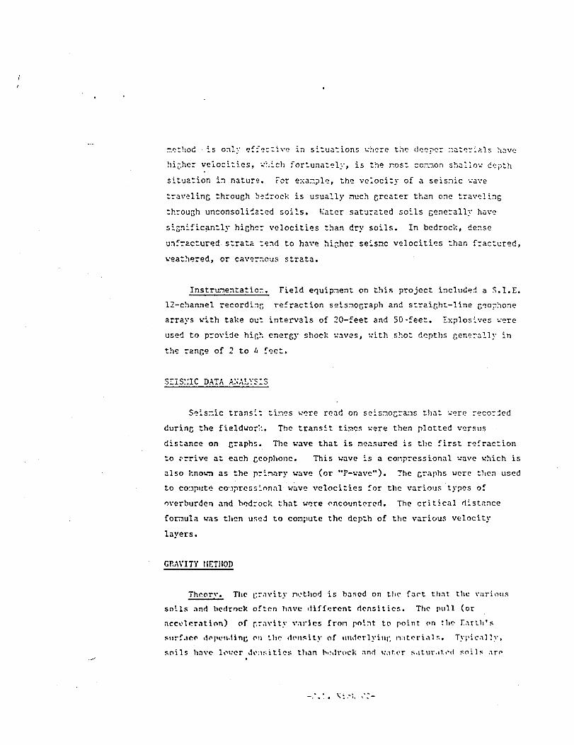
method is only effective in situations where the deeper ."iat»rials have
higher velocities, which fortunately, is the nost comon shallow depth
situation in nature. For example, the velocity of a seisnic wave
traveling through bedrock is usually much greater than one traveling
through unconsoli'iated soils. Kater saturated soils generally have
significantly higher velocities than dry soils. In bedrock, dense
unfractured strata tend to have higher seisnc velocities than fractured,
weathered, or cavernous strata.
Instrumentation. Field equipment on this project included a S.I.E.
12-channel recording refraction seismograph and straight-line geophone
arrays with take out intervals of 20-feet and 50-feet. Explosives were
used to provide high energy shock waves, with shot depths generally in
the range of 2 to 4 feet.
SIISXIC DATA ANALYSIS
Seisr.ic transit tines were read on seismograms that were recorded
during the fieldwor':. The transit tines were then plotted versus
distance on graphs. The wave that is measured is the first refraction
to ?rrive at each gcophone. This wave is a corpressional wave which is
also known as the primary wave (or "P-wavc"). The graphs were then used
to compute compressinn.il wave velocities for the various types of
overburden and bedrock that were encountered. The critical distance
formula was then used to compute the depth of the various velocity
layers.
GRAVITY METHOD
Theory. The gravity nothod is based on the fart th.it the various
soils and bedrock often have different densities. The pull (or
acceleration) of gravity varies froin point to point on the Earili's
siirf.ico ilopcMi.ting on the density of iindorlyini' ivitori.il r.. Typically,
soils have lower densities than hodroek and w.itcr s.ituv.it.i-il soils ,nro

denser tV.ar. dry soil'-. I" :. gravity survey, thick deposits of soils .-.re
distinguished by ano-.alously lov gravity neasurernents.
Gravity Fieldvor;'.. Ir. cor.i'jcting a gravity survey for the purpose
of neasuring depth of bedrock, a precision gravity neter is usea to
measure the acceleration of gravity at points alone traverse lines or in
a grid-like pattern. The r.-^asurenents on this project were r.ade with a
LaCoste c, Ronberg gravity -eter which is capable of high resolution work.
Land surface elevations of each gravity station were obtained to
well within -KJ.l foot by leveling. Station elevations were tieti to a
U.S. Geological Survey bench nark referenced to the nean sea level datun.
Gravity Data Analysis. Standard Hoii£uer data reductions were
applied to the field ncMsursr^nts. Base station values were fitted to
cor.puter generated tical curves to correct for drift. Terrain
corrections wore r.ade where necessary, '.."hen the various sources of error
are taken into consideration, nost of the computed gravity values arr;
considered within a rolatix-e accuracy of +0.03 nilligals. A r.illigal is
a unit of neasurenent used to quantify snail differences in
gravitational acceleration. One j~al is crjual to one centinetcr per
second per second, or 1000 nilli^als.
An inportant step in the analysis involves separating the effects of
soil thickness fron effects caused by largo scale density variations
within the underlying bedrock. In accomplishing this, maps and profiles
of both local and regional Kouguor gravity are prepared. Ncsilual
gravity values are then obtained by subtracting the regional fron tho
local gravity values. The residual gravity trends are of special
interest bccaur.c they correlate closely with the trend of the buried
liodrock surface.
Rc»lri<cU di'ptli ro -jnit.it inn? are n.iilo for e.u-li gravity st.vtio'i ir.i'ig .1

1. Kesiiual gravity.
2. Ground elevation
3. Estimated thickness of cry soils above water ta?le.
4. Density contrast for dry and water saturated soil versus
becroc!-: estimated fror. bedroc?. r.3.ps.
P.IISVLTS
The interpreted seisrr.ic results are presented in the forr. of
elevation profiles in Figure 1. The profiles show overburden (soils) and
bedroc'r. seis~.ic velocities that -•ere r.er.sured and the cor.puted derth of
bedroc'ri. The investigation renultert in two profiles; I'rofiles A ani '.
Because of the relatively deep Leiroc): on this project lone (500 to GOO
feet) seisr.ic arrays were used for r.jch of the -,:ork. This provides jood
information for cor.putin<; aeptli of bedrock, but ^ives a widely scattered
sar:plin£ of upper overburden velocities. Because of ti.is, velocity
changes are not precisely defined for the upper-.ost layer.
The following taMe -.itches the co~pi:terf seisr.ic velocities with
probable earth nnterinls:
Seismic Velocity Probable Earth "aterial
(feet per second)
1300 to 2000 rnr..ittirrtte't soils. ";iy v:irlnrl.
•1.1:1.!, ;-.r.ivi-l, silt, .1:1.1 cl.iy.

:l.iy?y) cr r.Dist (-.or saturated)
~rarrjlar soils.
.Loose, water-saturated overburden, "ay
incl-jde sand, gravel, silt or clay. Loose
sandy rills -ay lie within the upper end o:
this ranee.
£500 .l.'ater saturated co-.oact glacial till.
13,200 to 15,500. .Competent crystalline bedrock.
Profile A. This profile trends roughly r.ortheast - southwest
paralleling the .Souhe^an I'.iver. The co.'~.pute~ depth of bedroci". varies
fro~ s. r.inimr. of 63 feet near shotpoint 3 to a r.axir.ur. of 31 feet at
shotpoint i>. Seis.-.ic velocities indicate a thin layer of ur.saturated
loose sandy soils (1500 ft/sec) over co.npact water saturated glacial till
(t5'JO ft/sec) aloni; the southwest end of this profile. At shotpoints 2
and 3 a n".nr-surface seis-.ic velocity of 31i)0 ft/sec r.ay be indicative of
sor.e-.chat silty or clayey unsaturated soils, or sands and r,ravels
containing a relatively hich noisture content (not saturated). A thick
water-saturated layer in the 5000 to 5600 ft/sec ran^e is indicative of
loose overburden naterials, but the higher velocities nay indicate the
presence of loose sandy --.lacial till, r.elativ.-ly hich bcdrocl: velocities
of IS, 2(10 to lr>,j()f) ft/sec indicate? competent bedrock.
Profile I'. Profile Ti trt'iuls north - r..mt)> across the oast part of
the O.K. Tool (~rvi;':i:iy -jite. Tlif c<vT;mto.! (U'l'tli of '.icilroi-l; r.imv«; fi>r"i a
i- \ •Y.-J\\\ 'if -:] f.>rt .U :-.'i.i: I'uVil .'i to a -i.»\i' IT : »f "2 ;"••'•( .it --hut |<ui-it r>.

\ f.in near-sarf ac-: Iv'er ...t', i. volocitv of _!';.!',• :t/-->^c i:, '.-.:. :.;tivr_ of
loose ur.sit _:rat»;. ov.-rbjr :e~. 7~.-3 layjr ~s ;•. acrlai". V' a la; .r lav.n;
c vvlocit;. of 33oC' ft/sec -"licr; ~iy r 3~,r 2-->c-it loos.- wat:r 3j.f.r-.t jd
3".icial outwash ceposits and/or wat^r saturated loose sa~.Jy jlicial ^:I1.
-. Doiroc': velocity of 13,^00 f~/sec is -.-dica-ivo of co-poteat
crystalline bo^roc':.
li is li-:ely t.nat a "tidier, layer" of co-.pact glacial till '£500
ft/sec) overlies ieirocl: a:ross the site. Such a layer, if unzntecte.!,
wo-^lc! ca-J3'2 bcirocl: to appoar shallov;er to the seisr.ic refract.o-j net ioC
thar. its actual lepth. Tne depth uiscrepancy would be roughly in
proportion to the thic-:ness of the "hidden layer".
Co-.^uted Penth of Bedrock '.'.z^. The lepth of hedrock contour -ip in
Ti^jre 1 i; Das:d or. r.ot'. cr"'-v--y cr-d seio"ic -er.r. :re le-.t-;. -r-.v.ty
" easjre"e~.ts were "".ij,0 .".cross r.'jc . of ti° site LCC.IU^O of its
inaccessibility to t'.ie sois-ic -.otnod. vjch areas incluaod pcv;-^nt i-v!
t'ie Insiie of the :~.aiT h'jildinr. Goisr.lc r^fractl n hocricl; d"~th
i-.for~.atior. was the basis for a gravity .-.odel of layer thic'iness and
layer density for the site. 7ne r.ap shows t.iat the trend of tic bedrock
surface dips fror. west to east across the site. The shallowest bedrock
'l^ss than 10 feet) is found at two points near the west end of the sit",
while the deepest bedroc!: (over 90 feet) was detected along the east
bor.!or of t'.io site.
\CCIT.ACY OF SEISMC DATA
In c.enoral, exporiencf chov.-s that the co-ipnt'-'d soisnic rir>; ths at
shot points aro witliin t^n porcent of t!ie true d^ptli. It is usually
possible to ilctorr.ine the ip|>roxinate trend of P'O b^ilroc'.; surface
between rhot points. The depth accnr.icy 'f tho trend of tlie bci'.rocl;
:..irf.icf b^rwi-'a ..hot poi-it<= i<; so ••••what 1-^ss :'ITI the c" put-'il I'-ptli a
I'a^'li -'ii.1 of A '..''is .ic Hn-1. <MiM'->t l"i«'%«; hii'.h v-'or: • y ovr'ur 1 - % l i '. lyvs
"•: l.i J..;o~. botv-'o:. l.v.:ir v-jl-i-ty -.it-irir.!; ir.i 'li^-.-v-jlocity :.~:r-jc;
Su:h "hiidor. Ipyors" can c^.use errors ir. the co-.;r.;tiiiori of i»oarocl;
depth. Situatior.s v'i-jr-2 c low or velocity r.aterial is overlain bv a
hi;.ner velocity layer, car. result ir. a significant bedrocl: -T-3pth
co~.Di:tatior. error if this situation is r.ot iiar-n

APPENDIX B
NAI TEST PIT LOGS

TEST PIT FIELD LOG
naiN A I CEO
WEATHE
DEPTH
— 2' — ,
— 4' —
— 6* —
— \z' —
— 13' —
— u' —
LOGIST
R S.jr
PROJECT _ • TEST Pi
nfqCRIPTION r . K , T^^l rn ' FILE No
1 nrjVTIQN -il'or,!. •:•' HATF . .
' N0 ~t!r~P--.-.-O,
EXCAVATION E Q U I P M E N T ronm.1 r. rv - , - , . - .r*W»r»l. P^TBtCTOR G«OUNO E.EV ;..,., ,
nv. 60 'sWBlTftR TIME STARTED _ _ 1113jl<r WARE unnriCAWCITY CjyO. REACH 19 11
SOIL DESCRIPTION
e
1o
c* cc »
i 5
CVA -
b-kgrd
2
dry It brown and brown, f/c sand, some cravel,little silt.
may be fill component
yellow br f/c sand, little f gravel, tr silt.
various fcrown colored strata O-4" thick)
sonc strata cuite silty, -mottled,ethers ur.iforn r/c sand xred bandln1'
boulders, gravel, cobbles, little m/c sar.d (intcrstitia
sand moist •,3d!^:t,~^fS'£^3&f*s
rounded boulders color: light grey fcroun
some flattened,
becoming coarser at the base:
to tr nv/c sand, more pea gravel sizes
BOIh-v-M.B'measured WL (surface) : 11.4' below
surface '? 1700 hrs
HE COMPETED 1445
E*CAVtrroRT
di f f .
, lff .
d i f f .
rii'f
d i f f .d i f f .
f* . f f
80UUOERCOUNT
OTY CLASS
Many A
A
A3 B
Mnny 1
fMnv AMany A
A
BtUiXHNo
R E M A R K S ' - OVA readings 9 background level both in pit, excavated mat ' lIS1 casing installed for OW
TEST PIT PLAN LEGEND:
1 U- -H
T 0N O R T H
V O L U M E « . ; .
1 PROPORTIONS 1 ABBREVIATIONS! EXCAVATION
BOyLOER. COUNT J ILSifc lr.r,«uu
J i Z C "AHCt LtTTt" |T««£t (TR| 0 -10% C • CO*«SECL*S
f*'''|C
t*T10N "^"'""lUTTLtlLD 10-20% ,J/e'J«t?S
J*"»NO UHStH C l»"0 " • *>"/• 1 •" • ""OOHcuyd 'EL • itiLO*
1 EFFORT
-tt>W« S™^""»*•« I G R O U N D W A T E R
((.•••str ,'IMC -0 'CTcwL»t»C'NG JL.
( M B J I "

TEST PIT FIELD LOG
naiNAI GEOLOGIST
LEATHER --
PROJECT TEST PIT No nw.
nFSCRIPTION " f Tr,^i r« ' FILE No tfj
1 OPTION ^ I'-.-.rH iM! . DATE C,.,,.OT
EXCAVATION EQUIPMENT roiiun r. rv/ 2 7 0 1peNa^aJf; rn^THArroR GROUND E^EV i JjJ. —
--J.. B.-.'c J— .
•^FHiTntt =fliil TIME STARTED IJa<;amr v^.cr- MnnnCAOtTITY cur« RFACM IP f!
DEPTH
— 3' —
— II1 —
i V
SOIL DESCRIPTION
OVA -
bkgrd
OVA -
b'rcrd
top soil
It yellow brown vf/m sandy snme silt, tr gravel
becoming arey-grecn t mottled v.f/f sand, sone silt
light whitish b
f/c gravel, lit
&
BOH *
neasured 1O. (su
R E M A R K S ^ OVA background •1 • probably Aeolian
TEST PIT PLAN LEGEND;
con tact- sharp,
rown cobbles/boulders, some
tie IT./V.C. interstitial sand.
liA'-^^^X ur.it-becor.es coarser=C?2?3< w/depth: bigger boulders,
tr to little c/v.c. sand.
11.7-
rface) : 8.4' below surface
0 1700 hrs.
rou')Iily l.S' silt inbottT of w«ll screen
ME CO"""
EXCAVEFFORT
BOULDtRCOUNT
OTr a*ss
A
A
A
A
A
AB
IS
REMARKNo
1
1
• 4
I PROPORTIONS 1 ABBREVIATIONS! EXCAVATIONJ k- 15 -H BOULDER COUNT ! iL$£fi. ' f.-ft« ...
P Yfl'^/i
' 0NORTH
VOLUME t
Silt RANSECLASSlflC»TlO
LETTER |TRACt (TR) 0 • I0*/p C • COARSE
A ILITTLCILI) io-!0% | J/"."Ji^ ^ ,
B |SOMC (SO) ?0-55*,. 1 V ' Vt",
R c IAND 3S-iO% | 6N -PKOWSirtL • »tLLCw
EFFORT1 c CAST
:OAI'M IGROUMDWATERr
iHRSI ~

TEST PIT FIELD LOG
naiNAI GEOLOGIST
WFATHEH ,--iy
DeNatalc
PROJECT . ' TEST Pi
DESCRIPTION c.y.. Tool FI^E No
T No 0«^
5£D
10CATION Illford, M! OATF 9-26-S3
EXCAVATION EQUIPMENT GB rv ni.7-npF RATnR 7r iV ' - '~r' ^' • ^-'''''MT^ TIME STARTED , 1 ?rj^UAKF VAOF MnnFI
?•• .,..„,. CAP6CITT , cjr i RFACH '= fl
DEPTH
— z1 —
— 3* — i
B *
— 13' —
SOIL DESCRIPTION
OVA -bkcd
OVA -Lr.gd
2-
fill or topsoilIt. yellow br vf/n sand, and silt
1 7
-Sharp contact
whitish-trown cooblcs t ooulders, little m/vc
sand, f/c gravel (as r.atrix)^ boulders, rofcblos
i,VOV-«e. ). placod like stonewor
^JJ^^VjCT-o. fit toaether nicely.
with increasing depth:
more boulders than cotbles.
only v/c sand, f
estimated
BOH - 14'
/c gravel matrix
OVJ-4 1.1. C."p pf c.i = jn9) - )2 .1P'WL (top of qrour.dl'11.16'
roughly 1' of «ilt in-. ;J« well screen
WE COMPLETED __12£0_
E X C A VEFFORT
easy
easy
easy
diff.
diff.
di f f .
diff.
V
• iff.
diff.
V
diff.
Vji-f f r
diff.
cliff .
V
J» f f
eouLCE*COUNT
OTY O.ASS
A
A
A
A
A.B
A.B
A,B
A,B
A.B
r. n
REMARKNo
REMARKS1 OVA used to monitor organic vapors during progress of digging hole.Background levels observed throughout digging (bkgd«< ppm)
TEST PIT PLAN LEGEND: 1 PROPORTIONS 1 ABBREVIATIONSI EXCAVATION
J^K- _J BOULDER COUNT ! Uitfi. r.-riM
' 6NORTH
\OLUME *
rLA-JirlcImi. nr^rTNTAtTl!oNl'"l*a (TR| 0 - <0*/. C • COARSECL* jSIFtCATlDN DESIGN AT (On1 f /U FlNC 'O»•-,,- A lnTTitui) 10- ?W. r /c-rmt io
^t'A-O LA1GCH C 1 t>(l> JS-SO% 1 BN -BV-ONCur<J 'fL • UH.CW
1 EFFORTE EAST
-EDUM 1 g ffnCULT1
-0"151 IGROUNOWATER
^§^L

APPENDIX C
WATER LEVEL MEASUREMENTS

Uf-I
»3?.KA?.'GEAU ASSOCIATES, Ii,'C.
WATER-LEVEL MEASUREMENTS
C L I E N T O. K. Tool Cor.ranv PROJECT NO.
LOCATION .viifnrd. ?:H
NOTES
WELL NO.
OW-2
OK-1
OW-4
OK- 3
S-l
S-2
S-3
PP-IDC -*
oM-la
of/-1h
0
M-2
*Measurcd
"Initial r
DATE
9/27/83
9/27/83
9/27/83
9/27/83
9/27/83
9/27/83
9/27/83
9/27/S3
9/29/83
9/->9/fn
10/3/83
olow top o:
adir.gs
TIME
11:12 A
11:16 A
11:22 A
11:27 A
AM
AM
AM
12:02 P
15:30
steel edge
HELD
14.00
14.00
13.00
13.00
19.55
17.00
17.00
13.00
downstrea
WET
2.55
1.13
0.85
0.40
0. 56
3.26
2.67
2.36
•n side
DTW
11.45
12.87
12.15
12.60
19.09
13.74
14.33
10.64
HP -EL
274.73
724.38
272.63
273.68
267.52
265.15
262.77
288.58
277.93
277.93
275.34
W/L ELEV.
263.28
261.51
260.48
261.08
266.56
264.03
261.37
269.49
264.19
263.60
264.60

ASSOCIATES, K.'C.
WATER-LEVEL MEASUREMENTS
CLIENT O.K. Tool Company PROJECT NO.
LOCATION Mil ford, NH
NOTES Second round of measurements, rain day & night before
WELL NO.
OW-l
<-!!••- •)
r*T.-_ -5
S-l
5-2
S-3
M-la
••:-ib
v-~>o
X-3a
K-3b
O
K-5a
M-5b°
OW-4
"initial
DATE
10/6/83
i n/fi/p?
10/6/83
10/6/83
10/6/83
10/6/83
10/6/83
10/6/P.3
i n/A /R-3
10/6/83
10/6/83
10/10/83
10/10/83
10/6/R3
readings
TIME
0930
f T) c;
0910
0935
0920
0915
0940
0945
r>?'^*,
1015
1015
1300
1300
0905
HELD
14.00
i •>. . oo
13.00
—
--
—
16.00
16.00
i P. no
17.00
18.00
18.00
18.00
14.00
WET
1.15
1 .64
0.55
—
—
--
1.93
2.45
7 1 1
1.90
5.50
6.55
6.25
1.B3
DTW
12.85
1 1 ">£
12.45
0.81
1.04
1.26
14.07
13.55
in qq
15.10
12.30
11.45
11.15
12.17
MP-EL
274.38
">74 .71
273.68
267.52
265.15
262.77
277.93
277.93
T7S 34
272.34
272.34
272.35
272.35
272.63
W/L ELEV.
261.53
263.. 37
261.23
266.71
264.11
261.51
263.86
264.38
?fi4 45
257.24
260.04
260.90
261.20
260.46

;,QRMAN'DEAU ASSOCIATES, INC.
WATER-LEVEL MEASUREMENTS
CLIENT O.K. Tool Conr.anv PROJECT NO. 569
LOCATION Milford, NH Weather: clear, 40°
NOTES Complete synoptic survey of ML pts on OK property.
WELL NO.
OW-l
OW-2
OW-3
OW-4
S-l
S-2
S-3
M-la
M-lb
M-2
M-3a
M-3b
M-4
M-5a
.. M-r,h
H £>
DATE
10/21/83
10/21/83
10/21/83
10/21/83
10/21/82
10/21/83
10/21/83
10/21/83
10/21/83
10/21/83
10/21/83
10/21/83
10/21/83
1H/P1 X R T
i n / ? ! /ai
T I M E
1110
1100
1025
1020
1120
1115
10/30
0900
0855
0915
0930
0940
0950
1000
i m n
HELD
14.00
13.00
13.00
13.00
18.00
15.00
15.00
17.00
18.00
18.00
17.00
i 7 . nn
WET
1.20
1.73
0.49
0.94
4.05
1.48
4.16
4.00
5.55
3.63
3 .43
•< 9?
1 03
DTW
12.80
11.27
12.51
12.06
0.84
1.06
1/29
13.95
13.52
10.84
13.00
12.45
14.37
11. "57
n _ 7ft
14 9"1
MP-EL
274.38
274 .73
273.68
272.63
267.52
265.15
262.77
277.93
277.93
275.34
272.34
272.34
273.41
272.35
•^7?. IS
1 1 ~) 1 3
W/L E L E V .
261.58
263.46
261.17
260.57
266.68
264.09
261.46
263.98
264.41
264.50
259.34
259.89
259.04
2 5 R . 7 R
25R.V7
"* 5 8 "

;,PAI;;ORMAN'DEAU ASSOCIATES, INC.
WATER-LEVEL MEASUREMENTS
CLIENT O.K. Tool Comnzinv ' PROJECT KO. 56<
LOCATION Kilford, NH
NOTES Synoptic survey of wells prior to quality samples
WELL NO.
ow-i
OW-2
OK- 3
ot:-£
c_l
C-T
C _ T
X-la
M-lb
'.•-">
V-T j
K-3b
M-4
M-5a
M-^b
M-fi
i
DATE
11/7/83
11/7/83
11/7/83
1 i '!'?•>.
t 1 /- /O ">
1 1/7/83
11 f /p 7
11/7/83
11/7/83
1 1 /7 / fn
1 1 /" /p "5
11/7/83
11/7/83
11/7/B3
11/7/B3
i i y-7 /07
TIME
2:31 D
2.28 D
") - 2O n
-) -16 -
•3 . •»? -
3:31 p
' • ">c. p
10:45 A
10:43 A
11:4"? A
j-> . j^n p
12:04 p
12:48 p
1:16 n
1 -.19 p
J..C.1 p
HELD
14.00
13.00
13.00
1 "> ^0
15.00
15.00
13. on
1 ?n
15.00
16.00
16.00
16.00
i f i . n n
WET
1.96
2.35
1.81
?.34
1.66
2.23
T . l f i
T TO
3.63
2.55
3.23
3.10
. 1 , R R ...
DTW
12.03
10.65
11 .19
1] . i f iunderIn T f _ i
-0.1 f + )
-0 1 f ^ - i
13.34
12.77
9.°a
i \ on
11.37
13.45
12.77
12.90
Id 1? .,
KP-EL
274.38
274.73
27"1 .fio
^7?.< :,''
Tfi-7 CT
265.15
•760 7"1
277.93
277.93
• > ? = ; _ 34
•>•?•> }.!
272.34
273.41
272.35
272.33
T73.S4 _ _
W/L ELEV.
262.35
264.08
•>62..2Q
TA1 ^7
?CT -->
264.95
1p-> A"7
264.59
265.16
•><"•." ^0
^AO J4
260.97
259.96
25°. 58
259.45
-<-, o. . :r>
APPENDIX D
NAI TEST-BORING LOGS
•iPROJECT
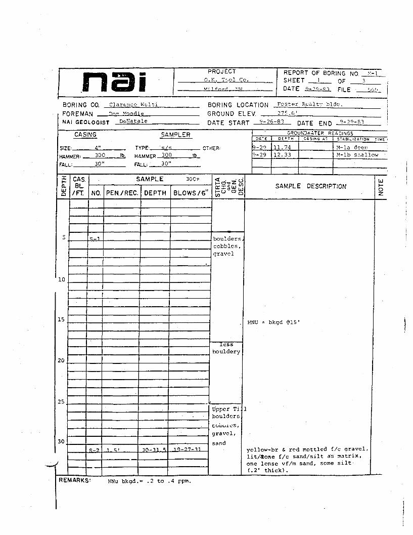
O.K. T'.ol Co.REPORT OF BORING NO. _SHEET ^_ I OF 3DATE M-pc._cX F[LE __
BORING
FOREM*
NAI GEO
CO.wLOG!
CASING
SI7F: 4"
HAW
FAL
X
0.UJQ
10
15
20
25
30
j
Clarer.ee Kc-lti BORING LOCATION roster
nor Moodie f
<iT Dc-f'atale [•
SAMPLER
ROUND E)ATE STAf
LEV 275.6'
3T 9-26-S3 r
Realty bide. ;
DATE END
II
9-29-S3 '
GROUrO<VAT£R READINGS
TYPF s/«; (1TMFR.MFR: 300 . Ib. HAVMFR 300 !b
.: 30" FALL: 30"
CAS.BL
/FT.
SAMPLE 300=
NO.
9-1
q_->
PEN./REC
i . •;•
DEPTH
10-31.5
BLOWS /6"
10-27-11
HO-oZ"criguj ,s»°»g
boulderscobbles,gravel
lessbouldery
Upper Tiboulders
coboj.cs,
gravel,
sand
DATE D E f T M
9-29 11.74
9-29 12.33
C A S I N G AT STtBi^lZi ' lON TIME
M-la deecM-lb sr.allow
SAMPLE DESCRIPTION
UNT* — V»Vrrr3 (31
ycllow-br & rod mottled f/c gravel,lit/ione f/c sand/silt as matrix,one lense vf/m sand, some silt(.2' thick).
UJ
o•z.
REMARKS1 HNu bkgd.«= .2 to .4 ppm.

naiiH-Q.UJO
35
40
45
50
3D
60
65
70
CASBL
/FT.
PROJECT0. K. Tool Co.•1i]_fr>rr? HH
SAMPLE
NO.
s-3
S-4
PEN./REC.
1.0'
1.0'
S-5
c-6
R-1
R-2
R-"?
1.0
s . n /i . o 'RQD=5'/4 '
S.OV4.81
s n • /4 6 '
DEPTH
40-41.0
45-46'
BLOWS/ 6"
47-82
51-62
55-56 47-83
60-fil . 5
6?. -67
67.5-72.
2.5-77.:
T7_in-5?
s
RQD=3.1/
4.8'
RQD=4 . 4 ' /4.6
<19t?^^WCX £ Lurh-0 o OrW a
Green
Till
pinkgranite
&granitegneiss
REPORT OF BORING NO. «-iSHEET 2 OF 3DATE Q-2=-pj_ PILE :^
SAMPLE DESCRIPTION
sample w
HNU, wash water 0 40.0'=bkgd.
Olive drab vf/f sand and silt, tr tlittle f/c gravel, extrenely compacsample moist. Lower Till.
Olive drab vf/m sand, and silt/claylittle to some v.c. sand/f. gravel,extremely compact sample moist.Lower Till.
Olive drai) vf/f sand and silt/clay,little to some vc sand/f gravel,extremely conpact. Sample moist.Till.
Similar to above, coarser fraction(v.c. sand/f. gravel) do-.inates.Till. HNu, S-5=bkgd
Relatively unweath'd pink granite f-pegmatite, fractured-most piecesroughly 3" long. HttU.wash water<? 60'=bkgd.
Pink and green coarse grained granit<& pegmatite. 1 or 2 near horizontalopen fractures. some ground-up mat '
Grey granite gneiss and pink & greerpegmatite as above. 2 high f breaks
UJt-O2
1
REMARKS:

naiD
EP
TH
75
80
CASBL
/FT.
PROJECT11 V Ti-.nl fn.
n.<i*or<3. KH
SAMPLE
NO.
R-4
PEN./REC
5.0' 74.8'
DEPTH
77.5-82.
BLOWS/ 6"
ROD=3 .8V4.8'
H£ zo'•-•'- ? LJuj
BOH
REPORT OF BORING NO. : '~-SHEET _i OFDATE ^-29-83 Fi(_r M -j
SAMPLE DESCRIPTION
Pink granite S pegmatite, and grar.igneiss; 1 or 2 high £ ticht fracturseveral drillers breaks.
•jji—O
ec.
REMARKS:

nai3 0 R I N G CO.
F O R E M A N
PROJECT REPORT OF B O R I N G NO. :•:-?0. K. Tool Co. S H E E T 1 nF 2
Miifr,rAr T™ HATE <'-2:--J:3 FILE S69
Clarc-r.ce wdti B O R I N G LOCATION ^-v- °* Scuhtsan RiverDon Moodie G R O U N D E L E V 2 7 3 . 0 '
NAI G£OLOfi iST D. DeKatale r
CASING
SI7F: 4"
SAMPLER
)ATE STAf
TYPF- S/S nTHFR:
,T o.2y-?,3 pATE r w n 9-30-63
C - K ( O U N D v V A T £ P R E A D I N G SD A T E C E P T N C A S I N G A T S T A B i ^ IZ A T , O N T i « E
UAMUFP: 300 Ib HiMMFR 300 16
FtLLi 30" FALL- 30"
XHLUQ
5
10
15
20
25
30
CAS.BL
/FT
SAMPLE 300#
NO.
S-l
S-2
PEN./REC. DEPTH
5.0-6.5
BLOWS/ 6"
7-9-13
.
9-11-13
<t . • f iPOTSZ"
S&'Ss
Fill
boul-icrs,cobbles,gravel,sand
sand &gravel
boulders,cobbles{Upper
Ti l l?)
SAMPLE DESCRIPTION
KNu, 0-5 during augerina = bkgd.
Dk reddish brown vf/m sand and silmetal shavings, f i l l .
HNu ? 12 ' , dur ing advance of corincbkgd.
begin drillina w/revcrt s roller bi
Note: driller has tried drill ingv/out nud, but water circulationcould not be nainta incd.
Lt yellow brown f/c gravcland c/vcangular sand. Sample wet.
HNu = bkgd.
UJt-0
R E M A R K S ^ HNu> bx<3d = o.2 ppm.

naia.UlQ
35
40
45
50
55
CASBL
/FT
PROJECT REPORT CF BORING NO. _>;-:>_0. K. Tool Co. SHEET ? OF 2.^:!ford, r:« DATE 9-29-83 Pn r ^fiq
SAMPLE
NO.
R-l
R-2
R-3
PEN./REC.
5.0 ' /3.0
5.0V2.5
S . O ' / J . O 1
D E P T H
38-43'
43-48'
A °.- c> ">. '
BLOWS/ 6"2^2"f-O § oliCO LJ
green
till
Lower
till
BOH
SAMPLE DESCRIPTION
Estimated top of compact t i l l~34'
Cored boulders, ground cobbles aridolive-green till.
Cored boulders, ground cobbles.
Cored boulders, ground cobbles andgreen till (mixture of silt/clay,f sand, f/c gravel).
Roughly 0.6' of till recovered.
UJ\-Oz
R E M A R K S '

PROJECTo. r.. Tool Co.Milford. NK
REPORT OF BORING NOSHEET I OFDATE ir-3-g? FILE
BORING CO. Hoi*--! BORING LOCATION -^- n-
N A I GEOLOGI!
CASING
SI7F: 4"
HAW
FALt
DE
PT
H
D
10
15
20
25
30
,y D. DeNatale r
SAMPLER
)ATE STAFrr in - - ? -= -> [DATE END
GROUNDWATER R E A D I N G S
TVPE- S/S HTHPR:urp.- 300 Ib. HAMMCP 300 Ib.: 30" FALL: 30"
CAS.BL
/FT
SAMPLE 3oo#
NO.
S-l
PEN./REC.
12"/18"
DEPTH
30-31.5
BLOWS/6"
i
17-22-18
KO<oZ$trxsuj;:]1-00 JiCO °
siltysand
boulderscoables,grav.
cobble,gravel ,sandlayers
O f i T E D E P T M C A S I N O AT S T A B I L I Z A T I O N T I M E
SAMPLE DESCRIPTION
H?;u, 5' to 25' = 4 0 ppm
It yellow-brown, stratified in thin( < 2 " > layers-vf/f sand layers,- f/cgravel, and m/v.c. sand, tr/littlesilt, (dense, wash water circulatedf u l l y ) ; silt layers HNu sanplc^bkc,
LJt-O
REMARKS:

I1-CLUJ
,Q
35
40
45
50
5b
60
65
70
naiCASBL.
/FT.
PROJECT REPORT OF B O R I N G NO. _.",-.o. y.. Tool Co. SHEET -^ op •>v.i1'--^ '-•" DATE i r _ 7 _ D T pii F
SAMPLE
NO.
S-2
S-3
C-&
S-5
S-6
S-7
PEN./REC
6"/18'
6"/18"
18" /18"
10"
DEPTH
35-3737-40
40-41.5
42-43
43-4545-46.5
50-51.5'
BLOWS/ 6"
16-19-4
3-3-3
5-5-5
54-57 i
i
60-61.5
66-67.5
70'-71.!
4-5-5
'
6-6-6
1 5-7-8
l~?-ostrcx £ oi^jen a
cobbles
cobbley^sand^fd
coarsesand,
andcrave 1
cpbbleylayer
coarse
sand,
f/m
sand
SAMPLE DESCRIPTION
Cobbley zone (dr i l ler)Lt grey br vf/f sand and silt,(cuttings) KNu = bkgd.
Lt. grey-browr. angular m/vc sand/
f gravel, little c. gravel, tr silt.illerj HNu=bkgd.
Lt brown angular m/vc sand, littlef. gravel, tr silt; uniform.
KNu sample = 1 to 2
Lt brown angular m/vc sand, littleto some f/c cravel,
KNu sample - bkga.
(driller)
Lt. brown angular m/vc sand,tr f gravel, tr silt, uniform
KNu = .8 for sample
Lt. brown angular m/vc sand/f grave]
tr/littlc c gravel, tr silt.HNu = bkgd for sample.
Color banded, orange and It. yellowbrown vf/m sand, tr silt.
REMARKS:

nas.A.t-o.01o
75
80
85
90
95
LOO
L05
no
CASBL
/FT
PROJECT REPORT OF BORING NO0. Y. Tool To. SHEET 3_ OF •>
Mil ford, NH DATE 10-4-83 pp £ --,--
SAMPLE
NO.
R-1
s-
P.-2
P-3
P.- 4
R-ri
R-6
PEN./REC.
p,"/^ n1
0/0
4. 3V10.01
5.0' /5.0'
pon=i .*>''.
5.0 ' /5 .0 'RQD=5.0/5.
«; n ' /^ n 'RQD=5.0/5.
3.0' /3.0'RQD=3/3
DEPTH
75'
o-\ ' _Bfi '
86'-
86'-96'
BLOWS /6"
70/no advar
9S'-101V
L01-1063
|nfi-i n3'
LJ.1-114
<0^Z-n^PCCX 2 Uj"'t-o 5 cs^en Q
boulderscobbles
(boulder:eTill &
boulders
wc^'dp i n K
aran't*-
unweath'cpink &greygranites-
near-verticalnvDvementsurfaces
BOH
SAMPLE DESCRIPTION
a few pieces of corase gravel,
cor^d boulders; gravel' crey-cree^isilt, tr/lit. f/vc sand sizes (tillas natri-'. (or.lv few inches tillrecovered) ; till overlies weatheredpink granite. HNu=1.0 for till sar.
Top 1.5': extremely weathered Sbroken pink granite - nuch breakagealong healed movement surfaces.Bottom: 3.5' unweathered pinkgranite and grey granite/granite gn«(qtz-feldspar-biotite) . Several
breaks — slickcn surfaces w/calcitemineralization; also many otherhealed S mineralized high £ to vert.sutures, si weathering along slickersurfaces.R-4 and R-5 : as above no drillersbreaks, fewer slick breaks, amountintact core increases w/depth.R-6 as above pink and grey granite4 or 5 slightly open high f movementsurfaces, calcite mineralization.
LI-C
1-
i
REMARKS:
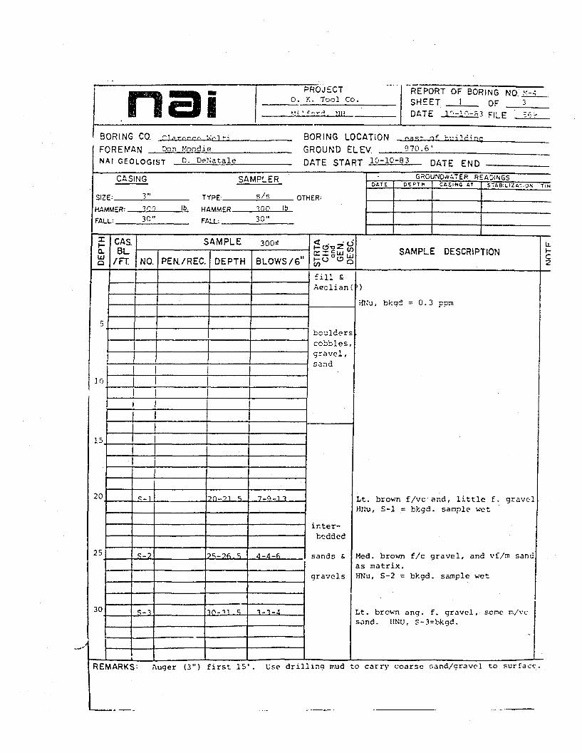
nai PROJECT0. K. Tool Co.
REPORT OF BORING NO *iSHEET I OF 3_DATE ir-i?-a3 FILE -A
BORING CO. riArr.r-.-f. \<r,~ --i BORING LOCATIONF O R E M A N Don .Moodie CN A I G E O L O n i S T D. DeNatale r
CASING
SI7F: 3"
SAMPLER
3 R O U N D E
)ATE STAf
TYPF: S/S OTHFR:
LEV 970.6 '5T 10-10-83 DATE pN n
G R G U N D A A T E R R E A D I N G S& f i T E D E f T M C t S l N S A T STas :LIZAT,ON T I N
HflMMSTR: TOO Ib. HflMMFP TOO Ib
FALL: 30" FALL. 30"
It-Q.
Q
5
10
15
20
25
30
CAS
/FT.
SAMPLE 300=;
NO. PEN./REC. DEPTH
1
c-1
S-2
S-3
?n-?i s
2S-26.S
30-Ti .«;
BLOWS /6"
7-0-1 ?
4-4-6
1-3-4
K0-o2°
£5S^Sfill £Aeolian
boulderscobblesgravel ,sand
ir.ter-bcdded
sands £
gravels
SAMPLE DESCRIPTION
HNu, bkgd = 0.3 cnm
Lt. brown f/vc and, little f. gravelHNu, S-l = bkgd. sample wet
Med. brown f/c gravel, and vf/m sandas matrix.Wu, S-2 = bkgd. sample wet
l<t. brown ang. f. gravel, sonc n/vcsand. HNU, S-3=bkgd.
U.1-2
REMARKS : Auger (3") first 15'. Use drilling mud to carry coarse sand/gravel to sur face .

I
PROJECT0. Y. Tool Co.;ilford.
REPORT OF BORING NOSHEET _2 OF _DATE IO-:'. F|LE 5-3")
CASBL/FT.
SAMPLE
NO. PEN./REC. DEPTH I BLOWS/6
<o
CO
SAMPLE DESCRIPTION
35
40
45
50
55
60
70
S-4 35-36.5 4-3-4
S-5 40-41.5
S-6 55-46.5
.5-7 0-51.5
6-9-10
Lt. brown & red brown m/vc sand,some'f. gravel; layer of roundedcoarse gravel, little m/vc sar.d atbase.
Lt. brown rounded f/c gravel, andf/vc sand, tr silt.
KNu, S-5 = 1.6 ppT.
6-9-14
76
S-B
Lt brown rounded f/c gravel,m/vc sand, tr silt.
HNu, S-6 =1.6 pen.
Lt. brown & red brown rounded f/cgravel, some vf/vc sand, tr silt.
HNu, S-7 = 1.6 ppri.
4-/18" b4-68 5-6-4
boulderscobbles
Lt yellow brown & grey brown finelyinterlayered vf/f sands 5 silts.Uniform top 6" underlain by It. brow:stratified c/vc sand and f. gravel.
HNu, S-8 = to 3 ppm.
cobbles
REMARKS:
H-Q.LJO
7
8
80.
90
95
100
1CASBL
/FT
nai PROJtCl REPORT OF B O R I N G NO. _.:•:--_o. K. Tool Co. SHEET "> np ->.'•ilford. IJH DATF i r . _ i « - o t n, c
SAMPLE
NO
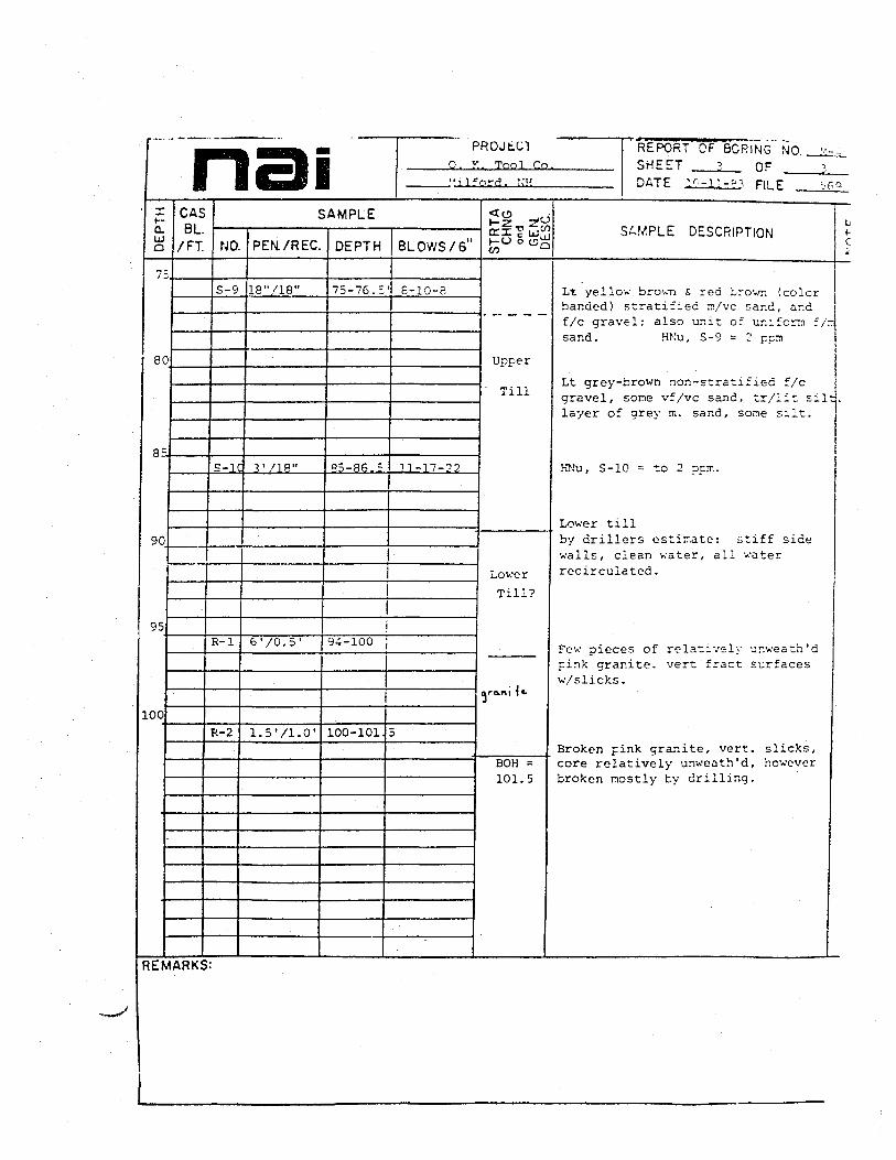
S-9
S-l
R-l
R-2
PEN./REC
18"/18"
3' 718"
6 - / 0 . 5 1
l.S'/l.O'
DEPTH
75-76.;
R5-86.5
BLOWS/ 6"
e-io-e
11-17-22
|94-100 j
100-101 5
<CD _.,t_->- TjlO
tri c wrfKU §0^CO C-
Uoper
Till
Lower
Till?
01-O.tM 1«-
BOH =101.5
SAMPLE DESCRIPTION
Lt yellow brown & red Lrown (colorbanded) stratified rr/vc sar.d, ar.df/c gravel; also unit of uniform ~/~sand. HKu, S-9 = 2 pen
Lt grey-brown non-stratified f/cgravel, some vf/vc sand, tr/lit siltlayer of grey n. sand, sonie silt.
KNu, S-10 = to 2 ppT..
Lower tillby drillers estimate: stiff sidewalls, clean water, all waterrecirculated.
Few pieces of relatively unwea th 'dpink granite, vert fract surfacesw/slicks.
Broken pink granite, vert, slicks,core relatively unweath 'd , howeverbroken mostly by drilling.
1
L1-C
|
REMARKS:
nai PROJECT:. Tnnl rn
•'.ilford.
REPORT OF BORING NOSHEET L__ OFDATE 1Q-S-B3 FILE
Clarcr.seBORING CO.FOREMAN _NAI G E O L O G I S T D. DeNatale
Don HoodieB O R I N G LOCATION esst of r i a n t at rror^rG R O U N D ELEV. 27?.6'DATE START 1Q-5-33 DATE END
CASING
SIZE:
HAMMER:.
•ALL:
4"300
TYPE-
HAMWER.
FALL".
SAMPLER
2/2 OTHER:300 ib
DATS=EADINGS
CASINS AT
CAS.BL
/FT.
SAMPLE 300*
NO. PEN./REC. DEPTH BLOWS/6'SAMPLE DESCRIPTION
UJ
O
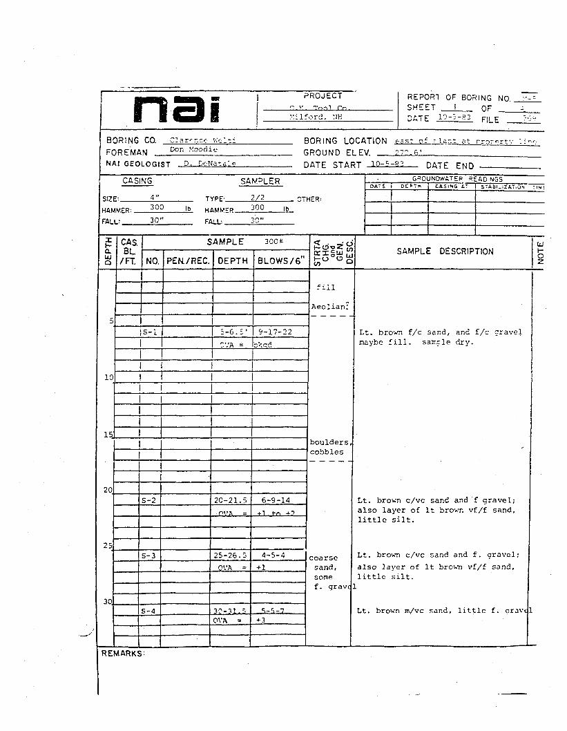
IS-1
10
I I
15
20
25
30.
S-2
S-3
S-4
fill
Aeolian;
5-6.5' 9-17-2;
'/A = okcd
Lt. brov.Ti f/c sand, and f/c gravelinaybe fill , sample dry.
20-21.5
25-26.5
OVA -
30-3 L,OVA =
ooulderscobbles
6-9-14
4-5-4
-i-l
S.-S-7
coarsesand,somef. gravt
Lt. brown c/vc sand and f gravel;also layer of It brown vf/f sand,little silt.
Lt. brown c/vc sand and f. gravel;
also layer of It brown vf/f sand,little silt.
Lt. brown m/vc sand, little f. nravc
REMARKS'-

naiXH-Q.UJQ
35
40
50
60
65
70
CASBL
/FT.
PROJECT REPORT OF B O R I N G NO >:--SHEET -. nF
Milf-rd "H D^TE IP- i -^- i Fll F
SAMPLE
NO.
S-5
PEM/REC.
£-6
S-7
12"/0"
DEPTH
40-41.5OVA =
50-51.5OVA =
BLOWS/ 6"
5-7-9bkad
6-7-9
bksd
55-56. 5j 7-11-17
60-61.5 29-54
<^_,0|5§ |
silty,sandy,gravel
(and
cobblesSboulders
Til'
SAMPLE DESCRIPTION
Lt. brown n/vc sand, soine f . gravel.
Lt. brown c/vc sand and f. gravel,tr silt. grains angular to subangular.
Lt. brown angular c/vc sand, androunded f/c gravelw/hole cased to 60', material becomehard to sample-gravel, cobbles orboulders,piece of gravel @ bot of shoe?
k-(~
c
j
REMARKS: c<ving driven to 80' in order to avoid overnight caving (BOH=110)

nai PRGJtU
O. K. Tool Co.
1 f r.'->.. '.'H
REPORT OF B3RING NOSHEET 3 OF
DATE j:-f-=.?. FILE _
CASBL
/FT.
SAMPLE
NO. PEN/REC. DEPTH BLOWS/6'SAMPLE DESCRIPTION
90
95
OC
S-S 75-76.5 7-54
R-l 8.0V2. 3 82-90 cored
P-2 5 . 0 ' / E . O ' 90-95 cored5' of ir.t ct till
R-4
P.-5
5.0/5.0' 95-100 Ic-nrod
5.0/5.0'
5.0/5.Q
I
100-105
105-110
Lower
Till
woath'dcoarsewhitegraniteverticalslicksurfaces
Lt. oranqe cro'.'n £/c g rave l , scnevf/vc sand/si l t ratrix. 'Jcoer Till
coredboulders, cobbles, gravel; orange-brown fine sar.d/silt coats somepieces.
Olive drab till: dense silt/clay sflc sand, and gravel, ccbble,boulder sized. sample quite dry.Tine lar.ir.atior.s in silt/clay.
Sar.e as above, however no boulders
Ton 4 ' : till as above
Bottom I 1 : weath 'd coarse whitegranite (q tz , feldspar,tiotite) .several near vertical breaks w/slicksided surface (a little loss odrill water here)Keath'd coarse white granite as abov5 or 6 mid-open high * fractures(slicks), several Irillers breaksrock can be crumbled in hand, but isintact. driller loses some waterhere.
EMARKS:

mtePROJECT
. K. "V^l
Mi If era. !<H
REPORT OF BORING NO.SHEET _.-.; OFDATE I'-'-Bl FILE _
CASBL
/FT.
SAMPLE
NO. PEM/REC. DEPTH BLOV/S/61tn
SAMPLE DESCRIPTIONUJt-O
11C 5 .0 /5 .0 ' 110-115
115BOH
as .azove
REMARKS:
PROJECTO.K. Tool Co.
REPORT OF BORING NOSHEET I OFDATE JLr.-i--_5i FILE _
B O R I N G CO. Clarc-r.ce- weltiF O R E M A N Don Hoodie
BORING LOCATIONGROUND ELEV. 270.7
NAI GEOLOGIST p. pfVai-a DATE START 10-12-83 DATE END 1G"14-S3
CASING
SIZE- !1_HAMWtR. ___3IL2_
FflLL:. 30"
TYPE
HAMMER.
FALL:
SAMPLER
s/s OTHER:
Ib
30"
GROUND^ATER READINGSCaSINC AT STABILIZATION Tit.
CAS.BL.
/FT
SAMPLE 300*
NO. PEN./REC. DEPTH BLOWS/6 HO
CO
SAMPLE DESCRIPTION
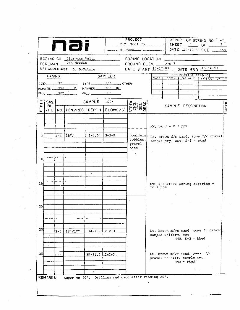
5-6.3' 3-3-9 boulderscobblesgravel,sand
KNu bkgd =0.3 cpm
Lt. brown f/in sand, sorr.e f/c gravesample dry. HNu, S-l = bkgd
10
20
25
30
S-2
S-3
24-25.=
30-31.5
HNU @ surface curing augcringto 1 ppm
2-2-3
2-2-3
Lt. brown in/vc sand, some f. gravesample uniform, wet.
HNU, S-2 = bkgd
Lt. brown m/vc sand, Jor«t f/cgravel tr silt , sample wot,
1INU « L-knd.
REMARKS: Auger to 20 ' . Drilling mud used a f t e r reading 20'

a PROJECT REPORT OF BORING NOSHEET - OFDATE !!•-'•>-*•* FILE _
o.UJo
CAS SAMPLE
/FT. NO. PEN./REC. DEPTH BLOWS/6SAMPLE DESCRIPTION o
2
40
60
65
70
S-4 IB"/
1 R" /
S-6
-1
40-41. 3-5-2
65.5-6
66-72
8-17-12
inter-beddedsand Sgravels
Lt. brown f/c gravel, and rr./vc sar.dtr silt.
HNU, S-4 = bkgd.
Lt. brown m/vc sand, little f. crave!HMJ, S-5 = bkgd.
cobbles
cobbles
UpperTill
HNU, wash water = bkgd.
by casing blowsbouldery
cobbley
Red brown & It brown coarse gravel,little to some vf/vc sand/f. gravel/silt. Upper Till. HNU, S-6 = bkgd
R-l cored boulder anc" aravel.
REMARKS:

naiD
EPT
H
80
85
90
CASBL
/FT.
PROJECT0. K. Tool Co.
Milfcrd. NH
SAMPLE
NO.
R-2
PEM/REC.
5'/5'
DEPTH BLOV/S/6"
86.5-91 5
!
i
j
•
<«^zoH-U § o^
Lower
Till
cinkgranite
BOH
REPORT OF BORING NO. •".-•-SHEET 3 OFDATE lo-l '-PI ni E - •
SAMPLE DESCRIPTION
HSU, wash water = bkgd
grey tillunweth'd pink granite, 1 or 2 breaks
NO
TE
!
REMARKS:
APPENDIX B
SOBFLOOR SOIL
ANALYSIS OF VOLATILE ORGANIC PRIORITY POLLUTANTS BYRESOURCE ANALYSTS, INC. (RAI)

RAI(603) 926-7777 Resource Analysis, Incorporated
Box 4778 Hampton. A7/ 03M2
TO:
Mr. Dennis SassevilleNonnandeau Assocites25 Nashua RoadBedford, NH 03102
J
PO « OK Tool
Date Received: 9-15-83
Lab Number: 2673
Date Reported: 9-29-83
IDENTIFICATION
Soil Smples for OK Tool Subfloor
PARAMETERSAMPLE DESIGNATION
Volatile Organics Analysis. Please see attached sheets.
Results expressed In mgA. unless otherwise designated Less Than
Van Kouwenberg/Pease/Foster
ANALYST DIRECTO
METHODS: *$Undtrd Milhodt tor tht Eiamliutlon of Wtltr tnd W»»t»w«ur" Urn Edition or ethtr EM ipprovtd mdhodologitiunlcii olh«rv»l»» dtilgniitd.

RAI
Resource A nalysts. IncorporatedBox 4778 Hampton. \HQ384?
VOLATILE PRIOTITY POLLUTANT DETERMINATION
Lab No. 2673 Analyst DM7/SPVK Date' Analyzed 9-21-83 (603)926-7777
EPA Method 624 []EPA Method 5030
ASTM Method D 3781-79 []
Parameter
Acro le inAc rv lon i t r i l sBenzene6is(chloromethyl )etherBrorao f ormCarbon letrachlorideChlorobenzeneChlorotf ibromomethorieChloroethar te2 -Ch lo rov iny l c the rChloroform
Dichlorobroir.oroethaneDichlorodif luromethane1,1-Dichloroethane1 ,2-Dichloroethane1,1-Dichloroethylene1,2-Oichloroprooane1,3-OichloropropyleneCthylbenzeneMethyl bromideMethyl chlorideMethylene chloride1,1,2,2-IetrachloroethaneTet rach loroethy leneToluene1,2-trans-Oichloroethylene1,1,1-Irichloroethane1,1,2-IrichloroethaneIr ichloroethyleneTrichlorofluoromethaneVinyl chloride
Sample Designation
Al
12
Tr
Tr
A2
300
Tr
Tr
•
Bl
28
Tr
B2
3.4
Tr
M e t h o d D e t e c t i o n Uni t : 0,2 ug/g 0.2 ug/g 0.2 ug/g 0.2 ug/g
NOTES: results are expressed as ug/g. Ho entry denotes "not detected",

RAI
Resource A nalysts, IncorporatedBo\ 477S Hampton. \H Q3S4;
VOLATILE PRIOTITY POLLUTANT DETERMINATION
Lab No. 267? Analys t nT Date Analyzed g-21-83 (603)926-7777
EPA Method 624 []EPA Method 5030
ASTM Method D 3781-79 []
Parameter
AcroleinAcrylonitri lsBenzeneBis(chloromethyl)etherBromoforiBCarbon TetrachlorideChlorobenzeneChlorodibromoipethansChloroe thaneZ-ChlarovinyletherChlorofoririDichlorobroflome thaneDichlorodif lurome thane1 ,1-OichJoroethane1,2-Dichloroethane1,1-Dichloroethylene1,2-Dichloropropane1,3-DichloropropyleneCthylbenzeneMethyl bromideMethyl chlorideMethylene chloride1,1,2,2-Ietrachloroethaneletrachloroethyleneloluene1,2-trans-Dichloroethylene1,1,1-Irichloroethane1,1,2-IrichloroethaneIrichloroethyleneIrichlorofluoro!nethan«Vinyl chloride
Sample Designation
Cl
1 Q
C2
L 2
Tr
•
Mithod Detection Unit: Q.2 ug/g 0,2
NOTES: All results are expressed as ug/g. No entry denotes "not detected".

APPENDIX F
SUBSURFACE SOIL
AMALYSIS OF VOLATILE ORGANIC PRIORITY POLLUTANTS BYRESOURCE ANALYSTS, INC. (RAI)

RAl
Resource Analysts, IncorporatedBox 4778 Hampton, ,\H 038-12
TO:
r Mr. Alton StoneNonnandeau Associates25 Nashua RoadBedford, NH 03102
J
PO « 830185 (603) 92fh7777
Date Received: 11-1-83
Lab Number: 2796
Date Reported: 11-17-83
IDENTIFICATION
Samples from project //569, OK Tool
SAMPLE DESIGNATIONPARAMETER
Volatile Organics Analyses by EPA Method 624. Please jee attached.
Acid and Base/Neutral Extractable Compounds Analysis. Please see attached.
Results expressed in mg/L unless otherwise designated < = Less Than
Russell n.ANALYST DIRECTOR
METHODS: "Slindird Mtlhodi for Iht Etimlntllon el W«l*r »nd W«it*w«t«r 1S1h Edition or elhtr EPA tpprevtd rrnihodologltiunleii elhtrwltt dtilgnittd.

RAI
BASE/NEUTRAL COMPOUNDS
Resource Analysts, IncorporatedBox 4778 Hampton. NH 038^
(603) 926-7777
DAT El 1-8-8 3 LAB {I 2796 ANALYST
IDENTIFICATION: Soil Samples
PARAMETER SAMPLE DESIGNATION
1C-SV 14D-SVAcenaphtheneAcenaphtyleneAnthraceneBenzidineBenzo (a) AnthraceneBenzo (a) Pyrene3,4-Benzof luorantheneBenzo (ghi) PeryleneBenzo (k) FluorantheneBis (2-Chloroetlioxy) MethaneBis (2-Chloroethyl) EtherBis (2-Chloro-isopropyl) EtherBis (2-Ethyl-hexyl) Phthalate4-Brornophenyl Phenyl EtherSutyl Benzyl Phthalate2- Chloronaphthalene4-Chlorophenyl Phenyl EtherChryseneDibenzo(a,h) Anthracene1 , 2-Dichlorobenzene1,3- Dichlorobenzenc1 ,4-Dichlorobenzene3,3'-Dichloroben7.idineDiethvl ohthalateDimethyl PhthalateDi-N-Butyl Phthalate2, 4-Dinitro toluene2,6-DinitrotolueneDl-N-Octyl Phthalate1 , 2-DiphenyihydrazlneFluornnthcnaFluoreneitexachlorobenzene^exachlorobutadieneHcxochlorocyclopentadlene •Hexachlorocthane
-r-1T*r"*'>-
continucd on reverse side

ACID EXTRACTABLE PRIORITYPOLLUTANT DETERMINATION
LAB 0 2796
SAMPLE DESIGNATION: Soil Samples
1C-SV
ANALYST RDF
UD-SVPARAMETER
2-Chlorophenol
2 , 4-Dichlorophenol
2 , 4-Dimethylphenol
4 , 6-DInitro-o-cresol
2 , 4-Dini trophenol
2-Nltrophenol
4-Nitrophenol
p-Chloro-m-cresol
Pcntachlorophenol
Phenol
2,4, 6-Tr ichlorophenolMethod Detection Limit
NOTES
0.2 - 5 ug/g 0.5 - 10 ug/g
All results are expressed as ug/g. No entry denotes "not detected". Method
Detection Limit varies with compound. Sample extraction and work up as per
SW 846 Section 3520.
Resource AnaJy-sts, Incorporated

RAIResource Analysts, Incorporated
Box 4778 Hampton, Mi OjC:2
(603) 926-7777
VOLATILE PRIOTITY POLLUTANT'DETERMINATION
Lab No. 2796 Analyst RDF Date Analyzed H-7-S3
EPA Method 624 [XI ASTM Method D 3781-79 [3
Parameter Sample Designation
Acro le inAcrylonitr i leBenzeneBis(chloromethyl)etherBromoforraCarbon letrachlorideChlorobenzeneChlorodibromomethsneCn lo roe thane2-ChlorovinyletherC h l o r o f o r mDichlorobronomethaneOichlorodif lurome thane1,1-Dichloroethane1,2-Oichloroethane1,1-Oiehloroethylene1,2-Oichloropropane1,3-Dichloropropylene[thylbenzeneMethyl bromideMethyl 'chlorideMethylene chloride1,1,2,2-letrachloroethaneletraehloroethyleneToluene1,2-trans-Oiehloroethylene1,1,1-Irichloroethane1,1,2-IrichloroethaneIrichloroethyleneIrichlorofluornmethaneVinyl chloride
1C-V 14D-V 16A-V
Trace
0.5Trace
•
75Trace
0.84
21A-V
0.10.051.1
Trace
Method Detection U«it: 0.2 ug/g 0.2 ug/g 0.06 ug/g 0.05 ug/g
M01tS;All results are expressed aa ug/g. No entry denotes "not detected". Sample
preparation and work up as per SW 866 Method 5030. Instrumental analysis aa per
EPA Metjod 624.

RAIResource Analysts, Incorporated
Box 4778 Hampton. .\'H 038-^2
(603) 926-7777
VOLATILE PRIOTITY POLLUTANT 'DETERMINATION
Date Analyzed H-7-83Lab No . 2796
EPA Method 624 K3 ASTM Method D 3781-79 []
Parameter
AcroleinAcrylonitrileBenzeneBis(chloroirethyl)etherBromofornCarbon letrachlorideChlorobenzeneChlorotJibromomethsneCht.oroe thane2-ChlorovinyletherChloroformOichlorobronomethaneOichlorodiflurome thane1 ,1-Oichloroethane1 ,2-Oichloroethane1,1-Oichloroethylene1,2-Dichloropropane1 ,3-OichloropropyleneEthylbenzeneMethyl bromideMcthjl chlorideMethylene chloride1,1,2,Z-IetrachloroethaneletrachloroethyleneToluene1,2-trans-Oichloroethylene1,1,1-Irichloroethane1,1,2-TrichloroethaneIrichloroethylenetrichlorofluoromethaneVinyl chloride
Sample Designation
42AB-V
61
O."i2
«1AB-V
1 .•}
1.8
•
Method Oetictlon Unit: 0.05 ug/g 0.05 ug/g
KOTES; So entry denotca "not detected". AIL results are expressed as uy/y. Samnle
preperation and \rork up as per SW 846 Metho'd 5030. Instrumental analrsls as per.
EPA Method 624.

APPENDIX G
MONITORING WELLS
ANALYSIS OF VOLATILE ORGANIC PRIORITY POLLUTANTS BYRESOURCE ANALYSTS, INC. (RAI)

RAI
Resource A nalysts, IncorporatedBOM 4778 Hampton. \H 0384?
TO:
! B
Mr. Douglas De NataleNormandeau Associates25 Nashua RoadBedford, Hew Hampshire 03102
1
J
P0 * 830205
Date Received: 11-8-83
Lab Number: 2822
Date Reported: 11-22-83
IDENTIFICATION
Samples from project 569 (OK Tool)
PARAMETERSAMPLE DESIGNATION
Volatile Organics Analysis by EPA Method 624
NOTE: Samples M7, M8 and M9 were for quality control only. They werespiked samples furnished by the N.H. WSPCC.
Results expressed In mg/L unless otherwise designated Less Than
1
_____ x-s, _____ —<^o rrr\^- ^ Russell n. vnoi..-./.!-., 11\uC^\/\^ \^*rei^Ll.
ANALYST " DIRECTOR1"
METHODS: 'Standard Mtlhodi lor Iht Ciamliullon of W«Ur and Wailtwaltf 1Slh Edition or othtr EPA *pprov*d mtthod«lo«tt»unltn othtrwli* dtilgnalad.

RAIpage
Resource Analysts, IncorporatedBox 4778 Hampton Mi O.'S-'"1
(603) 92£-7777
VOLATILE PRIOTITY POLLUTANT DETERMINATION
Lab No. 2822 Analys t RDF Date Analyzed 11-17-83
EPA Method 624 [] ASTM Method D 3781-79 []
Parameter
AcroleinAcry lon i t r i leBer-zeneBis(chlo rone thy] )etherBromoforaCarbon TetracnlorideChlorobenzeneChlorodibronomethsneCMoroethane2-ChlorovinjfletherChloroforn
0 ich lor ob ronome thaneOichlorof l i f luromethane1,1-Dichloroethane1,2-Dichloroethane1,1-Oichloroethylene1,2-Oichloropropane1 ,3-OichloropropyleneCthy lbenzeneMethyl bromideMethyl chlorideMethylene chloride1,1,Z,2-tetr3chloroethanele t rach loroethy lenetoluene
1 ,2-trans-Oichloroethylene1,1,1-trichloroethans1,1,2-Irichloroethan8IrichloroethyleoeTrichlorof luoromethaneVinyl chloride
Sample Designation
Mia Mlb (20')
•
Mlb (35') M7
377032
Trnrp
"?P
Mi6Q
7267
94
8S
,
Method Detection Unit: 5 ug/L 5 ug/L 5 ug/L 5 ug/L
MTCS; All results are expressed as ug/L. No entry denotes "not dctetced". Trace de
compounds observed belov the method detection limit.

RAlResource Analysts, Incorporated
Box 4778 Hampton, \H 0384:
(603) 926-7777
VOLATILE PRIOTITY POLLUTANT DETERMINATION
Lab No. 2822 Analyst RDF Date Analyzedj,i-x7-g3
EPA Method 624 [tf ASTM Method D 3781-79 []
Parameter
AcroleinAcrylonitri leBenzeneBis(chloromethyl)etnerBromoformCarbon letrachlorideChlorobenzene
Sample Designation
M8
910
Chlorod ibromomethsne 12Ch lo roe thane2-Chlorovin_yJetherCh loro form JTrai-oDichlorobronomethaneDich lorod i f lurome thane1,1-Dichloroethane1,2-Dichloroethane1,1-Oichloroettiylene1,2-Oichloroprooane1 ,3-OichloropropyleneCthylbenzeneMethyl bromideMethyl chlorideMethylene chloride1,1,2,2-!etrachloroeth3r,ele t rach lo roe thy leneloluene1, 2- trans-Oi chloroe thylene1,1,1-Irichloroethane1,1,2-IrichloroethaneIr ichloroethyleneIr ichlorof luoromethane
'Vinyl chloride
5109
147
6
11
M9
3670•n
Tri^fl
443675
7566
99
90
»
M2C20M
Trace
•
M2f31M
Trace
Method Detec t ion Llilt: 5 ug/L 5 ug/L 5 ug/L 5 ug/L
ROTCS: All results are expressed aa ug/L. No entry denotca "not detected".Trace denotes compound observed belov the method detection limit.

RAI
Resource A nalysts, Incorporated
Box 4778 Hampton. ,\'H 038-C
(603) 926-7777
VOLATILE PRIOTITY POLLUTANT DETERMINATION
Lab No. 2822 Analyst RDP Date AnalyzedjLl-17-83
EPA Method 624 fe] ASTM Method D 3781-79 []
Parameter
AcroleinAcrylonitr i leBenzeneBis(chloromcthyl)etherBromofof"Carbon Tetrachlor ideC'iloroben;eneChlorodibronofethsneChlcroethane2-Ch lo rov iny le therChloroformDichlorobronome thaneDichlorodi f luronethane1,1-Oichloroethane1 ,2-Oichloroethane1,1-Oichloroethylene1 ,2-Dichloropropane1 ,}-Dichloropropylene[thylbenzeneMethyl bromideMethyl chlorideMethylene chloride1,1,2,2-Ietrachloroethanelet rachloroethy lenetoluene1,2-tr3ns-Dichloroethylene1,1,1-Irichloroethane1,1,2-IrichloroethansIrichloroethyleneIrichlorof luoromethansVinyl chloride
Sample Designation
M3a(108')
6AOO
20
370
"
K3b(20')
370
1109
53
«
M3bf46')
Trace
490
25021
100
irace
M3b(72')
Tfarp
410
27014
88
irace
Method.Detec t ion Unit: 20 ug/L 5 ug/L 5 ug/L 5 ug/L
NOUS: All results expressed as ug/L. Ho entry denotes rtnot detected".
Trace denotes compound observed belov the method detection limit.

4 of 6
RAIResource Analysts, Incorporated
Box 4"& Hampton. \H 03842
(603) 9:5-7777
VOLATILE PRIOTITY POLLUTANT DETERMINATION
Lab No. 2822 Analyst RDF Date Analyzedll-17-83
EPA Method 624 DQ ASTM Method D 3781-79 []
Parameter Sample Designation
AcroleinAcrylonitri leBenzeneBis(chloromethyl)etherBromofora
Carbon letrachlorjdeChlorobenzeneChlorodibromomethsneChloroethane2-ChlorovinyletherCh lo ro fo rmDichlorobromomethaneOichlorodi f lurome thane1,1-Dichloroethane1 ,2-Oichloroethane1,1-Oichloroethylene1,2-Oichloropropane1,3-DichloropropylenetthylbenztneMethyl bromideMethyl chlorideMethylene chloride1,1,2,2-ietrachloroethanele t rach lo roe thy lenetoluene1,2-trans-Dichloroethylene1,1,1-trichloroethang1,1,2-lrichloroethaneIrichloroethylenetr ich lorof luorome thaneVinyl ctiloride
M4(20«)
4600
65
M4(57')
5500
50
•
MA(82') M5a(108'}
Trace
5200
30
Trace
2119
Trace
Hit hod bi tect ion Unit : 50 ug/L 50 ug/L 50 ug/L
ROtCS: All result!? qytj e^cpresaed a% ug/L. No entry .denQtea "not
Trace denotes compound observed below the detection limit.

page 01 b
RAIResource Analysts, Incorporated
Box 4778 Hampton, \H 03842
(503) 926-7777
VOLATILE PRIOTITY POLLUTANT DETERMINATION
Lab No. 2822 Analyst RDF ' Date Analyzedn-17-83
EPA Method 624 DrJ ASTM Method D 3781-79 []
Parameter
AcroleinAcryloni t r i leBsnjene8!s(chloromethyl)etherBromofo rdCarbon letrachlorjdeChlorobenzsneChlorodibromome thaneChloroethane2-ChlorovinyletherCnlorof oraDich lor obronome thaneDie hi orodiUurorae thane1,1-Oichloroethane1 ,2-Oichloroethane1,1-Dichloroethylene1,2-Oichloropropane1 ,3-DiehloropropyleneEthylbenzene
.Methyl bromideMethyl chlorideMethylene chloride1,1,2,2-IetrachloroethaneTetrachloroethyleneToluene1,2-trans-Oichloroethylene1,1,1-Irichloroethane1,1,2-IrichloroethaneIrichloroethyleneIrlchlorofluoronethineVinyl chloride
:•_
** >
.. A.» ...
Sample Designation
M5b(20')
25,000
traceTrace
400
M5b(54')
Trace
35,000
200
500
•
•
M5b(80')
30,000
Trace
930
M6(20')
13,000
Trace
110
f
Method OertcUoh'limit;. 200 ug/L 200 ug/L.^. 250 ug/L 100 ug/1
BOIES; t-^g-CT-i.-- All results are expressed as ug/L.' Wo entry denotes "not detected"
trace denotes compound observed belov the method detection limit.

page 6 of 6
RAIResource Analysts, Incorporated
Box 477S Hampton. A// 03842
(603) 926-7777
VOLATILE PRIOTITY POLLUTANT DETERMINATION
Lab Analyst Date Analyzed 11-17-83
EPA Method 624 ASTM Method D 3781-79 []
Parameter
Acrolein*crylonitril«
Benzene8is(chloroi»ethyl)ether8roircfof8Carbon TctrachlcrideChlorobenzeneChlorodibromome thaneChloroethane2-ChlorovinyletherChloroformOiehlorcbromoffle thaneOichlorodif lurome thane1,1-0ichloroethan«1,2-Dichloros thane1,1-Oichloroethylene1 ,2-Dichloropropane1 ,3-OichloropropyleneEthylbemeneMethyl bromideMethyl chlorideMethylene chloride1,1,2,2-IetrichloroethaneTetrachloroethyleneToluene1 ,2-trans-OUhloroethylene1,1,1-lrichloroethjne1,1,2-Irlchloroethane(richloroethylentIricMorofluoromethanitVinyl chloride
." ,- t • *.v . " .
\;—.,.-... ..
Sample Designation
M6(A8r)
13,000
Trace
130
* '.'• '. . ' V
*- .
-
M6W)
18,000
Trac^c
200
r • " •'•*«••
.
sifQ)
.• ' :
•
S3fo>
•, ;
• - ..„«,. 100 ug/L --~, 200 ug/L-- ,-rv - 5ug/L_--- • 5 ug/ll'lll *",.!,".{,.' " . _.<,* ' UlC ' "' ' J- I ' ;'-
ug/L
Trace dendtes compound oleerved below the method detection limit.

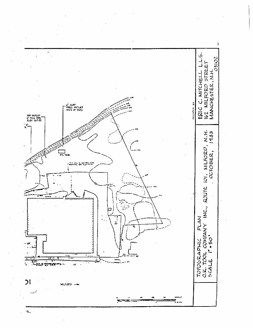
r_au it THE pirtcT tSiu^T of, KM
, M5L IT2
T»t LST LIWE4 4WOWW W£T£ TaK-EW TEOM TutMJ 'PJ.-: OF o»- TOOL o: »j^ «IL»OBP, u u *£."ip«r e-i eostcr B TC^O. t_i • t<«o, utw
M M . JULY 21. "Ifc
H
naiDECEMBER 1983
ROUTE
Figure 1.2-2. O.K. Tool Company property, Milford, New Hampshire. O.K. Too?
LA "
\
J,uJ
o^2 m
oJt-
iVJ
•t.
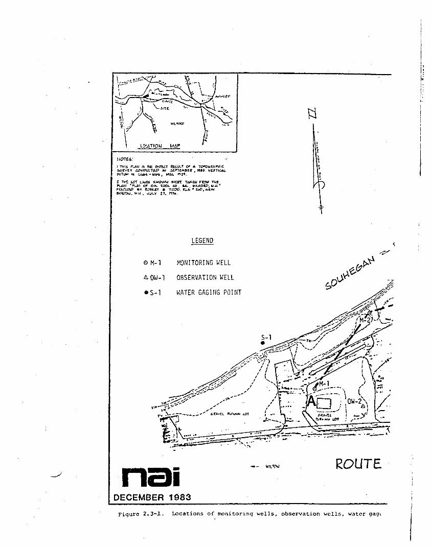
LJXATIOW MAP
UGTEt:
i -ma r_4u it T»e etiULt or, n»i
2 TVC. UTI LlUfci &MOW/U WtPt Tt^BJ•'•_£.'! <X OK. TOOL CD. UL . MtLTOV, U U. '
«t ETStCT » TOPO. Cli • l^O, wt«i . NU , OULY 17. n7»
LEGEND
OM-1 MONITORING WELL
&OW-1 OBSERVATION WELL
• S-l WATER GAGING POINT
naiDECEMBER 1983
ROUTE
Figure 2.3-1. Locations of monitoring wells, observation wells, water gagt
— ' 111 *%
is
S3-J CO
uJi-
2VJ
vj S O
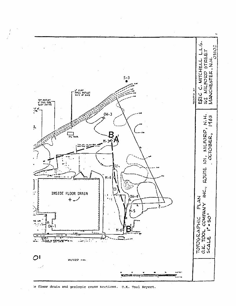
ie floor drain and geologic cross sections. O.K. Tool Report.

Icr.
Tit PlftCT QiLltT Of A T0*«u itrrtMtte , n»J VERTICAL.
K.T^" it uits -wwt. MSL r»n
1 TWt LCT uwfi 1UOVAJ IMtTt TWtEU rcau Tut*r_ai or OK. TOOL u> . IJL . KIL«»K>, u u •
13Ire(ex-
. KU . JULY IT,
_f|.= FILL
J.= WASTE
= NATURAL SOIL
= APPROX. EXTENTOF FILL/WASTE
SAMPLE POINTS LOCATED ATGRID INTERSECTIONS UNLESSOTHERWISE NOTED= •
naiDECEMBER 1983
1 k> II II
ROUTE
Figure 3.2-1 Surface Soil Characteristics. O.K. Tool Report.

34
M ft K> 17 It. M 1 It tS tl
•0 CO
£T
CH
ELL M
. O3I
O2
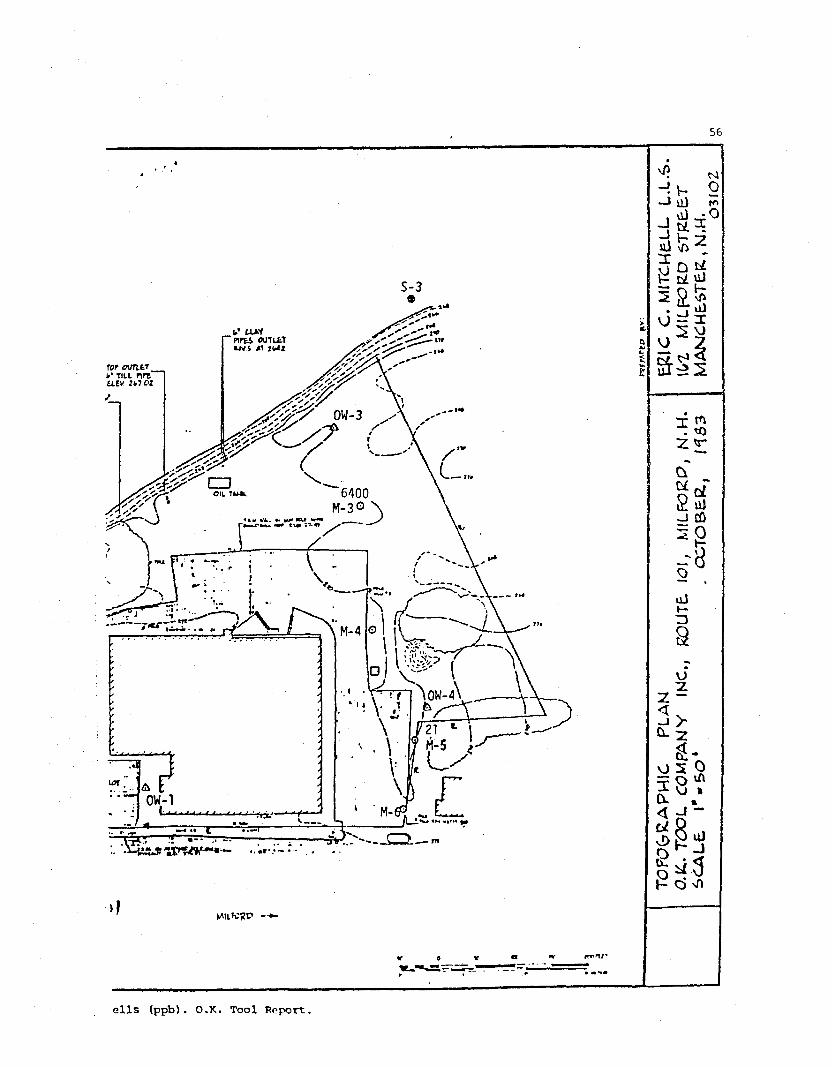
E£tC
Cl(,1
M
tM
AN
JCM
E.S
TE.P
.
TY
PO
GR
AP
HIC
P
LA
N A
MD
UX
AT
IOM
OF
SAM
PUN
fe
PO
INTS
O.fc
. TO
OL
C
OM
PA
NY
IM
C.,
RO
UTE
. IO
I ,
MIL
RJR
P,
N.H
.S
CA
LE
l"
-5O
' CC
TO
BE
.C.,
/<f5
3
LCCiTIOKJ MAP
NOTES.
I TWIi r-lU It ft plCtiT CfcSULT of A
LOT LIUti iWOWW WtEt TW-ftJ FEW THl'r_« or on, TOCX. u> . la. tmmu>,uu'
»T C fctTT B TOPD t_i • IKO, WtW. MM . JULY Z7, Mlk
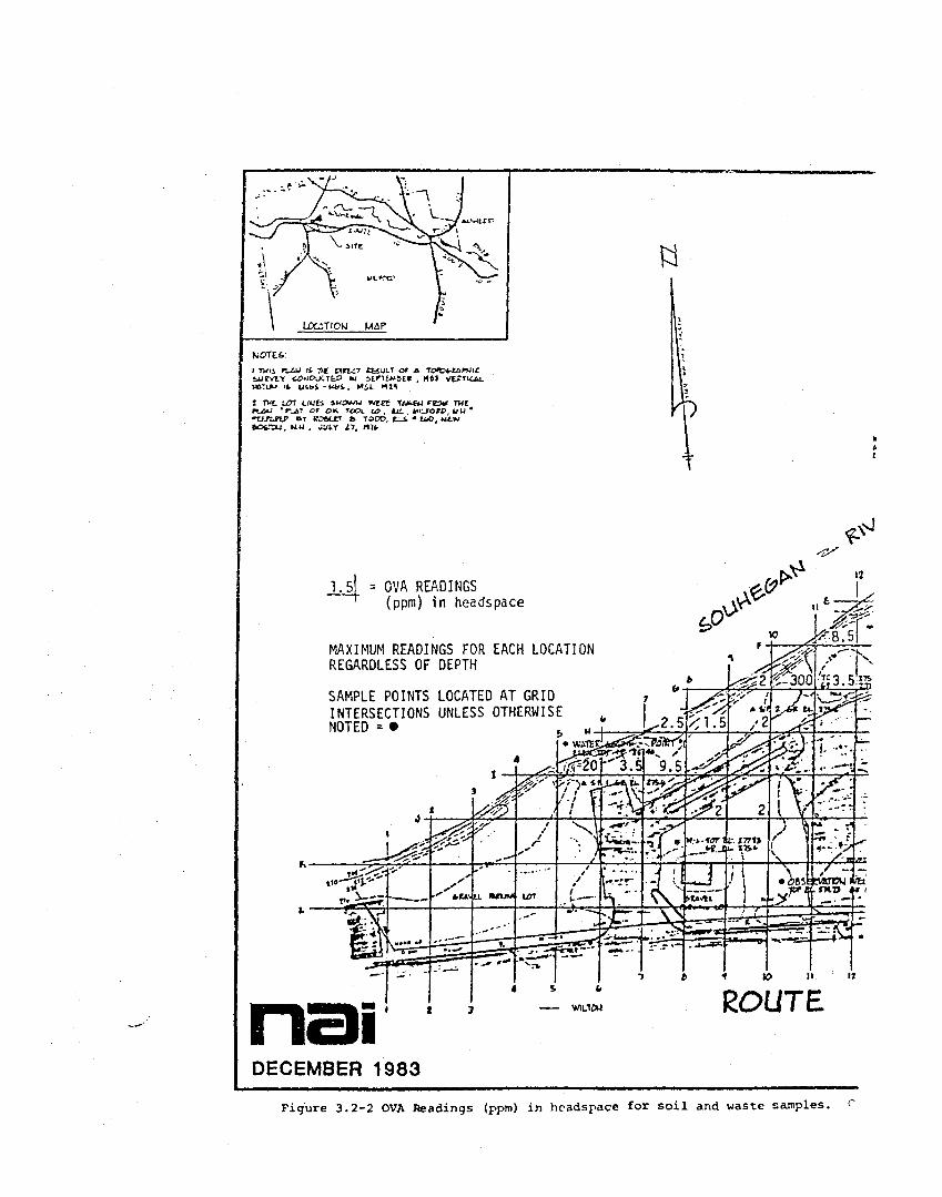
1.51 = OVA READINGS(ppm) in headspace
MAXIMUM READINGS FOR EACH LOCATIONREGARDLESS OF DEPTH
SAMPLE POINTS LOCATED AT GRIDINTERSECTIONS UNLESS OTHERWISENOTED = •
naiDECEMBER 1983
ROUTE
Figure 3.2-2 OVA Readings (ppm) in headspace for soil and waste samples,

35
TT»fc'1HE
-*•__
+
4
£
-
•
V.
'I
x-J
?;
OU1'LtV I
U
ss
rtiTnrtt70J
^JL »
'rr*.1.'10•«•
•%
h_*
K--
MM
•k. • IM-
>
?'
1
U.
rJi's
If5^1UT •»
>1000
3* *•
~^L-J .'. "'
f *" »H— • «
J
" r
l*Mlff
9
tM
u
1
•
T0TU. XI
uv
iAY4 CUTutT
17
IDOIL TA*J£j
•I
>iooro
9
1.5
- WAl- ft< M
""loo~. |
"..:--
r— ",x
rf1
>1000
nj WULW »LB
& ik 1
VMLWPD
*
\
fff' 'c
1.4"
TsV
r^V- [:
'i(7tS
"•••
" •^•^
1 \
^
(. V
' 1
€iY5 A'''
1.5f (JRiEE' rof n-
tff ti.0
~60u
^ 40
-
° - i . .1 —^-'
\
'. i • .
. .' *
1
'I
•"V
It
A1.5
ViTOJ ' «l
r»"»
, 2
>iodo
1.4
%\1\
^>\ • f fV .»\"
\
— e:
5 I
•0t
tlfv _
s\« «
\!a-uw
/* "•r
/^^~
u. niuu ix>t
1 .2
Jt
fc' I/ JH77
A
f
tl ZJ77
«. ZT«
. - - - n
\-A~—
i.t CTJJtE TIO
fr /
1 i '
«•* iff
i r
9
'' 1^EL iiit- U-fttO
*t tt, to. ratIL.J'07
I 1
V
!3
•-
K""
" > S\
— • • • •
.B
3 1
tte
'4
•
, fr
\ . 1
\-^<
f
4
•C tuU'U'
EglC
C
. M
ITC
WE
.LL
L.L
.t>
.!(r
Z.
MIL
R2K
D 6
T£t£
TM
AN
CW
tST
aK ,
N.M
.0
3IO
2
TO
PO
GR
AP
HIC
P
LA
N A
MD
LC
CAT
IOM
OF
6A
MP
UW
G
PO
INTS
O.K
.. T
CX
3L
CO
MP
AN
Y
IMC
., R
OU
T6.
/O
I ,
MIL
FC
RP
, N
.H.
SC
ALE
l"-5
0'
CC
TO
BE
R.,
HB
3
Tool Report.

LOATIOM MAP
TI« nrtcT BKULT of *iu airrt*<&E» ,
i TMIJ nsuevtrPiTUM 14
1 TXt LOT LUJE4 4MOWW W£K TiX-EU FCMlt TUtPU6»J ' r_« Of OK. TOO. 0> . ILJC. . HILRSfP, U U '
p »T ecfttrr B TOIO. ri-t • ii<o, wtiw. KU-. OUUY zi, n't
LEGEND
© M-l MONITORING UELL
&OW-1 OBSERVATION WELL
• S-1 WATER GAGING POINT
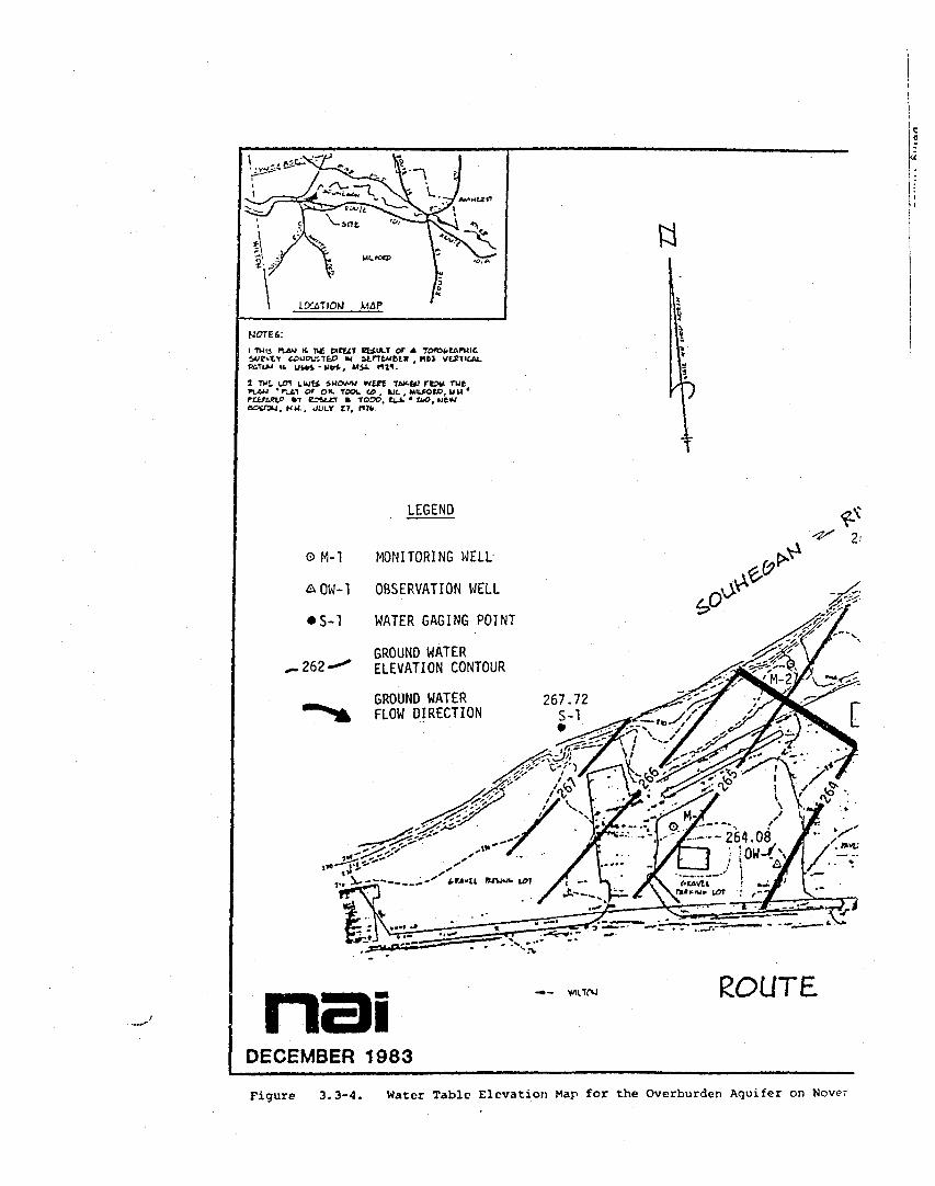
GROUND WATER— 262— ELEVATION CONTOUR
GROUND WATERFLOW DIRECTION
naiDECEMBER 1983
ROUTE
Figure 3.3-1. Water Table Elevation Map for the Overburden Aquifer on Septc-

1983. O.K. Tool Report.

ITAU 14 7U« tarfcCT EfcSULT OfuouiTto * atrrtwati , nti
P^TJM 14 UiVi-WK*. Mil. nil.
2 T^L LOT Lwti »ue>w/M iveet TU^EU rtaw rut-r_ti or on. TOOL co, uc.. MILFOCD, uu *
> treter B TODO. rt c • uio, wtvw, NH.. JULY 27, H)»
LEGEND
o H-l MONITORING WELL
AOW-1 OBSERVATION WELL
• S-l WATER GAGING POINT
—262GROUND WATERELEVATION CONTOUR
GROUND WATERFLOW DIRECTION
naiDECEMBER 1983
ROUTE
Figure 3.3-2. Water Table Elevation Map for the Overburden Aquifer on Octo!

<jim.trlilt r..V H70J
v/iJ- v- S>-i vil r«, d) -0
viJ
li
u)»-Z3
VJZ
h
'83. O.K. Tool Report.

LKiTIOM MAP
MOTEt:
n_4U It Tie
CK.T1X
EiULT OF Aitno-sti , nt>
&L nj1.
T U7T LIUE4 SMOWM INfft T£«-Eil rC^U TUt*r-_£T <X OH. TOOL CO. IUC. . KILtOlD, U U '
»t z^tcr » TOPO, tu. • tuo, wtw80SJ3U. MM . JULY Z1, ">»
LEGEND
OM-1 MONITORING WELL
AOW-1 OBSERVATION WELL
WATER GAGING POINT• S-l
.262-GROUND WATERELEVATION CONTOUR
GROUND WATERFLOW DIRECTION
naiDECEMBER 1983
ROUTE
Figure 3.3-3. Water Table Elevation Map for the Overburden Aquifer or. Octo1

.->
xJJ
K>, O
uJi-
2VJ
US O
>B3. O.K. Tool Report.
LOCATIOW WAP
I TUli riAU K, 11C tXtU1 BEiULT OF Aa)upu:TfcP HI itrrtMMR , MH
LOT LUJti JUCVAJ WEJTt TAW.BJ rtJK TUC• rj,i of o». toot u> . to. . nctforo, u u •
»T emrr » TOTD. <^_i. • tut>, wtwM. . JULY Ii, nJfc
O M-l
AQW-1
• S-l
^.262-
LEGEND
MONITORING WELL-
OBSERVATION WELL
WATER GAGING POINT
GROUND WATERELEVATION CONTOUR
GROUND WATERFLOW DIRECTION
naiDECEMBER 1983
ROUTE
Figure 3.3-4. Water Table Elevation Map for the Overburden Aquifer on Mover

«."* IST
-IK p—> lli i, O) -O
• I *-U
J23
vJ»-
aVJ
_v) S 0
, 1983. O.K. Tool Report.

1 Trl*. \O\ CUJB 1MCWU IVUS TAK-EiJ FCOW TUtn-au *rji-! o* c+~ TOOL co . «JL . KU-IOIP, w u •
. NX . JJLT zi,
OM-1
AQW-1
• S-1
. 262—
LEGEND
MONITORING WELL
OBSERVATION WELL
WATER GAGING POINT
GROUND WATERELEVATION CONTOUR
GROUNDFLOW
WATERDIRECTION
nasDECEMBER 1983
ROUTE
Fiqurc 3.3-6. Potentiomctric Surface Elevation for the Bedrock Aquifer on Oc

S-3
jv- 2, a) -O
3 Q
ui
H iasl
VJ
a^.8<!l -I -
, 1983. O.K. Tool Roport.

(JOTEt:i -mis ruivj H. TIC pirtiT EBULT or A
&iountp <u itrttfc>ti , nt>IUM-UM, MIL i«
t TWI LOT LUft luoww wut Tav-EU rtaw rutPUAU 'r_ii or or- TOOL <c uc . MU.FOU), uu '
P >T C2UTT • TOOD, t i • UX>, WtW, N U . OULY I', rut.
GM-1
S-l
LEGEND
MONITORING WELL
OBSERVATION WELL
WATER GAGING POINT
GROUND WATERELEVATION CONTOUR
GROUND WATERFLOW DIRECTION
naiDECEMBER 1983
WILTS*-' ROUTE
o>o
Figure 3.3-7. Potentiometric Surface Elevation for the Bedrock Aquifer on K

7, 1983. O.K. Tool Report.
jlU ft T>C tXKCf SESULT Ct AC0WPIXTW M StrTtWBE.1 , HM
UtW. -Utri, MiL OJ1.
1 1X1 LOT LUE1 1UWWW WEZC T&K.EU rtOU TMCn-au -r^Ai or OK. TOOL <D . uc . MIUOEO. u it *natrtf »T eottcr » TOCO. ZLi • no. wt»/BOU3U. NU , JULY IT, H7k.
©M-1
OMW-I
A ow-i
• s-i
ND
TR
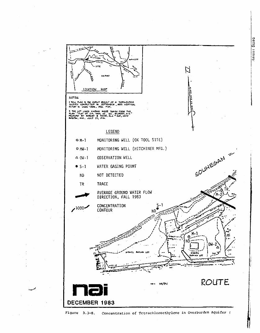
LEGEND
MONITORING WELL (OK TOOL SITE)
MONITORING WELL (HITCH1NER MFG.)
OBSERVATION WELL
WATER GAGING POINT
NOT DETECTED
TRACE
AVERAGE GROUND WATER FLOWDIRECTION, FALL 1983
CONCENTRATIONCONTOUR
<^
naiDECEMBER 1983
WX.1M ROUTE
oCD
5CO
25c
Figure 3.3-8. Concentration of Totrachloroethylene in Overburden Aquifer (

.K. Tool Report.

L2J1TIOM MAP
MCTEt:
i TUIJ IVAU it ue pirfxi BE&ULT of AIU lLr7tMC.il KM.
i. Wit nzv
l ivt un LW64 luowu »vtrt TUM-EU rejw rueruAU • r_&T or OK. TOOL 03 , me . MILK>U>, u u '
BY eseerr B TOPD. « c. • tw>, utw. MU . JULY 27. MTk.
OM-1
AQW-1
• S-l
NO
LEGEND
MONITORING WELL
OBSERVATION WELL
WATER GAGING POINT
NOT DETECTED
naiDECEMBER 1983
ROUTE
Figure 3.3-9. Concentration of Tctrachiorocthylene in three Bedrock Mo-
>l
56
jv- Q_j vvi^O
dfe2
V- £ii 2 aS
a§S2^<
c
laJ £0
oJh-n
\J
OS 0= o^
ells (ppb). O.K. Tool Report.