transmission media - thammasat...
TRANSCRIPT
ITS323
TransmissionMedia
Design Factors
Guided Media
WirelessTransmission
Wireless Media
Transmission Media
ITS323: Introduction to Data Communications
Sirindhorn International Institute of TechnologyThammasat University
Prepared by Steven Gordon on 23 May 2012ITS323Y12S1L04, Steve/Courses/2012/s1/its323/lectures/media.tex, r2334
ITS323
TransmissionMedia
Design Factors
Guided Media
WirelessTransmission
Wireless Media
Contents
Design Factors
Guided Media
Wireless Transmission
Wireless Media
ITS323
TransmissionMedia
Design Factors
Guided Media
WirelessTransmission
Wireless Media
Design Factors
I Key concerns are data rate and distance: maximise bothI Design factors:
I BandwidthI Transmission impairmentsI InterferenceI Number of receivers
ITS323
TransmissionMedia
Design Factors
Guided Media
WirelessTransmission
Wireless Media
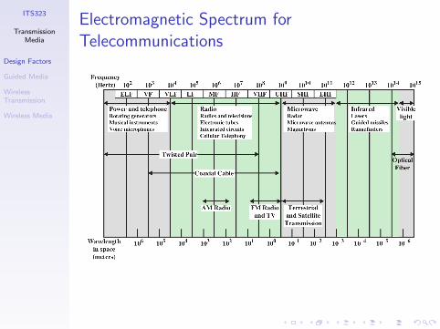
Electromagnetic Spectrum forTelecommunications
ITS323
TransmissionMedia
Design Factors
Guided Media
WirelessTransmission
Wireless Media
Contents
Design Factors
Guided Media
Wireless Transmission
Wireless Media
ITS323
TransmissionMedia
Design Factors
Guided Media
WirelessTransmission
Wireless Media
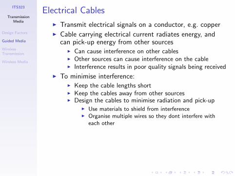
Electrical Cables
I Transmit electrical signals on a conductor, e.g. copperI Cable carrying electrical current radiates energy, and
can pick-up energy from other sourcesI Can cause interference on other cablesI Other sources can cause interference on the cableI Interference results in poor quality signals being received
I To minimise interference:I Keep the cable lengths shortI Keep the cables away from other sourcesI Design the cables to minimise radiation and pick-up
I Use materials to shield from interferenceI Organise multiple wires so they dont interfere with
each other
ITS323
TransmissionMedia
Design Factors
Guided Media
WirelessTransmission
Wireless Media
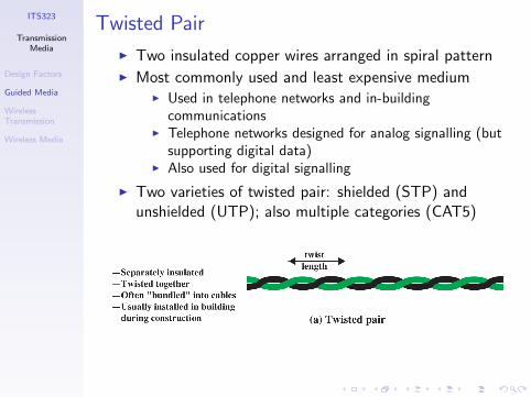
Twisted Pair
I Two insulated copper wires arranged in spiral patternI Most commonly used and least expensive medium
I Used in telephone networks and in-buildingcommunications
I Telephone networks designed for analog signalling (butsupporting digital data)
I Also used for digital signalling
I Two varieties of twisted pair: shielded (STP) andunshielded (UTP); also multiple categories (CAT5)
ITS323
TransmissionMedia
Design Factors
Guided Media
WirelessTransmission
Wireless Media
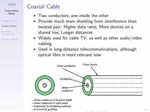
Coaxial Cable
I Two conductors, one inside the otherI Provide much more shielding from interference than
twisted pair: Higher data rates; More devices on ashared line; Longer distances
I Widely used for cable TV, as well as other audio/videocabling
I Used in long-distance telecommunications, althoughoptical fibre is more relevant now
ITS323
TransmissionMedia
Design Factors
Guided Media
WirelessTransmission
Wireless Media
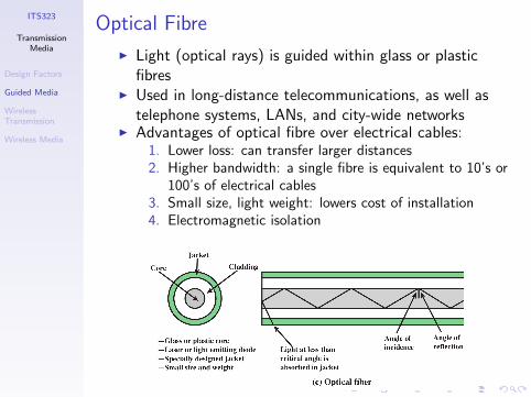
Optical Fibre
I Light (optical rays) is guided within glass or plasticfibres
I Used in long-distance telecommunications, as well astelephone systems, LANs, and city-wide networks
I Advantages of optical fibre over electrical cables:1. Lower loss: can transfer larger distances2. Higher bandwidth: a single fibre is equivalent to 10’s or
100’s of electrical cables3. Small size, light weight: lowers cost of installation4. Electromagnetic isolation
ITS323
TransmissionMedia
Design Factors
Guided Media
WirelessTransmission
Wireless Media
Comparison of Guided Media
Electrical Cables
I Moderate data rates: 1Gb/s
I Maximum distance: 2km (twisted pair); 10km (coaxial)
I Cheapest for low data rates
I UTP: easy to install, susceptible to interference
I STP, Coaxial Cable: rigid, protection againstinterference
Optical Cables
I Very high data rates: 100Gb/s+
I Maximum distance: 40km
I Expensive equipment, but cost effective for high datarates
I Difficult to install
ITS323
TransmissionMedia
Design Factors
Guided Media
WirelessTransmission
Wireless Media
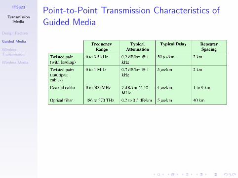
Point-to-Point Transmission Characteristics ofGuided Media
ITS323
TransmissionMedia
Design Factors
Guided Media
WirelessTransmission
Wireless Media
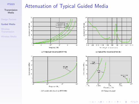
Attenuation of Typical Guided Media
ITS323
TransmissionMedia
Design Factors
Guided Media
WirelessTransmission
Wireless Media
Contents
Design Factors
Guided Media
Wireless Transmission
Wireless Media
ITS323
TransmissionMedia
Design Factors
Guided Media
WirelessTransmission
Wireless Media
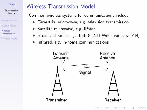
Wireless Transmission Model
Common wireless systems for communications include:
I Terrestrial microwave, e.g. television transmission
I Satellite microwave, e.g. IPstar
I Broadcast radio, e.g. IEEE 802.11 WiFi (wireless LAN)
I Infrared, e.g. in-home communications
Transmitter Receiver
Antenna AntennaReceiveTransmit
Signal

ITS323
TransmissionMedia
Design Factors
Guided Media
WirelessTransmission
Wireless Media
Antennas
I Antenna converts between electrical current andelectromagnetic waves
I Waves are within the Radio Frequency (RF) band of 3kHz to 300 GHz
I Antenna characteristics are same whether sending orreceiving
I Direction and propagation of a wave depends onantenna shape
I Isotropic antenna: power propagates in all directionsequally (spherical pattern, ideal)
I Omni-directional antenna: power propagates in alldirections on one plane (donut)
I Directional antenna: power concentrated in particulardirection
I Power output in particular direction compared to powerproduced by isotropic antenna is antenna gain [dBi]
ITS323
TransmissionMedia
Design Factors
Guided Media
WirelessTransmission
Wireless Media
Antenna Examples
See http://www.cisco.com/en/US/products/hw/
wireless/ps469/
ITS323
TransmissionMedia
Design Factors
Guided Media
WirelessTransmission
Wireless Media
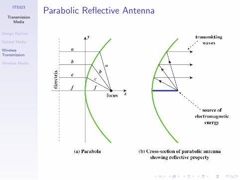
Parabolic Reflective Antenna
ITS323
TransmissionMedia
Design Factors
Guided Media
WirelessTransmission
Wireless Media
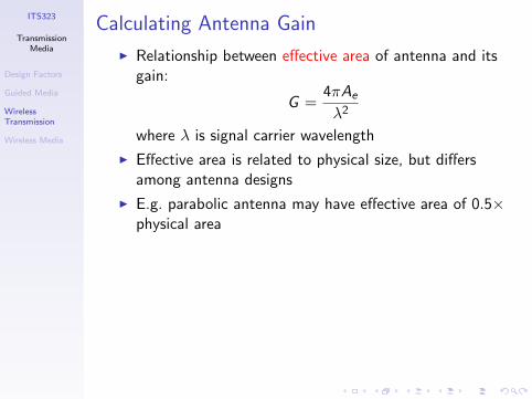
Calculating Antenna Gain
I Relationship between effective area of antenna and itsgain:
G =4πAe
λ2
where λ is signal carrier wavelength
I Effective area is related to physical size, but differsamong antenna designs
I E.g. parabolic antenna may have effective area of 0.5×physical area
ITS323
TransmissionMedia
Design Factors
Guided Media
WirelessTransmission
Wireless Media
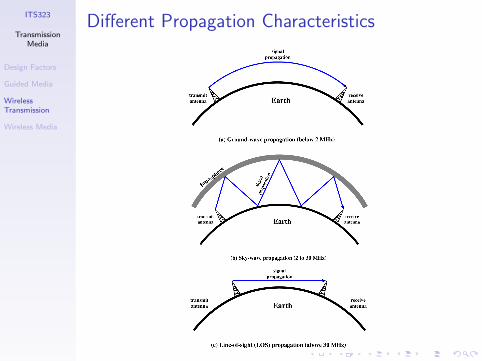
Wireless Propagation
I Ground Wave Propagation (below 2 MHz): signalfollows contour of Earth, e.g. AM radio
I Sky Wave Propagation (2–30 MHz: signal reflectedbetween ionosphere and Earth, e.g. amateur radio,international radio stations
I Line-of-Sight Propagation (above 30 MHz): signal notreflected; antennas must be in effective line-of-sight;used for most communications
ITS323
TransmissionMedia
Design Factors
Guided Media
WirelessTransmission
Wireless Media
Different Propagation Characteristics
ITS323
TransmissionMedia
Design Factors
Guided Media
WirelessTransmission
Wireless Media
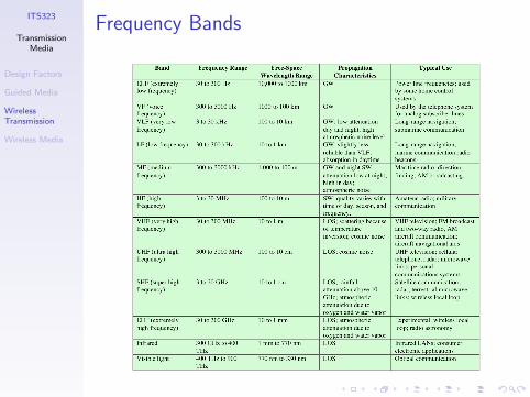
Frequency Bands
ITS323
TransmissionMedia
Design Factors
Guided Media
WirelessTransmission
Wireless Media
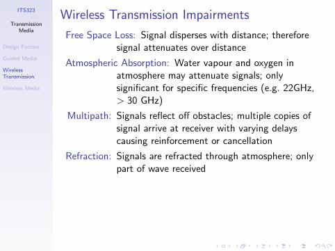
Wireless Transmission Impairments
Free Space Loss: Signal disperses with distance; thereforesignal attenuates over distance
Atmospheric Absorption: Water vapour and oxygen inatmosphere may attenuate signals; onlysignificant for specific frequencies (e.g. 22GHz,> 30 GHz)
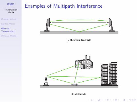
Multipath: Signals reflect off obstacles; multiple copies ofsignal arrive at receiver with varying delayscausing reinforcement or cancellation
Refraction: Signals are refracted through atmosphere; onlypart of wave received
ITS323
TransmissionMedia
Design Factors
Guided Media
WirelessTransmission
Wireless Media
Examples of Multipath Interference
ITS323
TransmissionMedia
Design Factors
Guided Media
WirelessTransmission
Wireless Media
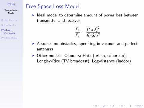
Free Space Loss Model
I Ideal model to determine amount of power loss betweentransmitter and receiver
Pt
Pr=
(4πd)2
GtGrλ2
I Assumes no obstacles, operating in vacuum and perfectantennas
I Other models: Okumura-Hata (urban, suburban);Longley-Rice (TV broadcast); Log-distance (indoor)
ITS323
TransmissionMedia
Design Factors
Guided Media
WirelessTransmission
Wireless Media
Example of Path Loss
Two parabolic antennas with diameter 1 metre; frequency 5GHz; transmit power 1 W; distance 1 km. What is requiredreceive power threshold of receiver?
ITS323
TransmissionMedia
Design Factors
Guided Media
WirelessTransmission
Wireless Media
Contents
Design Factors
Guided Media
Wireless Transmission
Wireless Media
ITS323
TransmissionMedia
Design Factors
Guided Media
WirelessTransmission
Wireless Media
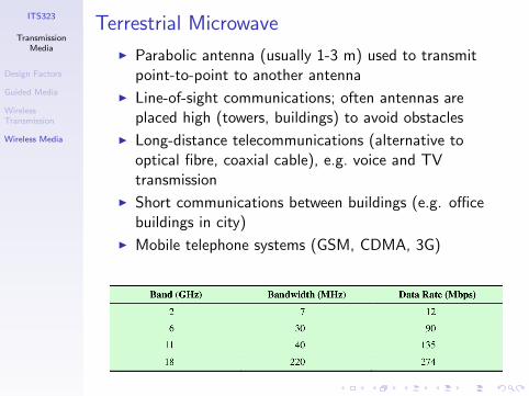
Terrestrial Microwave
I Parabolic antenna (usually 1-3 m) used to transmitpoint-to-point to another antenna
I Line-of-sight communications; often antennas areplaced high (towers, buildings) to avoid obstacles
I Long-distance telecommunications (alternative tooptical fibre, coaxial cable), e.g. voice and TVtransmission
I Short communications between buildings (e.g. officebuildings in city)
I Mobile telephone systems (GSM, CDMA, 3G)

ITS323
TransmissionMedia
Design Factors
Guided Media
WirelessTransmission
Wireless Media
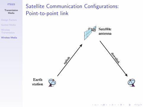
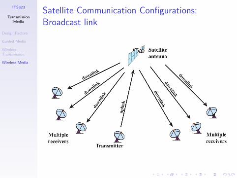
Satellite Microwave
I Communications satellite acts as microwave relaystation
I Links two or more ground/earth stations
I Receives signal on one frequency (uplink), repeats oramplifies, and transmits on another frequency(downlink)
I Point-to-point or broadcast configuration
I Geostationary Orbit (GEO): satellite appears stationaryfrom Earth; cover about 1
3 Earth surface; 36,000 kmabove Earth
I Low Earth Orbit (LEO): 100’s of km above Earth; orbitEarth every 1–2 hours; footprint with radius of3000–4000 km
ITS323
TransmissionMedia
Design Factors
Guided Media
WirelessTransmission
Wireless Media
Satellite Communication Configurations:Point-to-point link
ITS323
TransmissionMedia
Design Factors
Guided Media
WirelessTransmission
Wireless Media
Satellite Communication Configurations:Broadcast link
ITS323
TransmissionMedia
Design Factors
Guided Media
WirelessTransmission
Wireless Media
Applications for Satellites
I TV distribution
I Long-distance telephone transmissionI Private business networks
I Very Small Aperture Terminals (VSATs) allow for lowcost Earth stations
I Global positioning, e.g. GPS
ITS323
TransmissionMedia
Design Factors
Guided Media
WirelessTransmission
Wireless Media
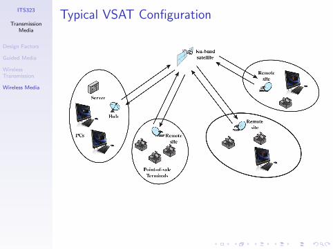
Typical VSAT Configuration
ITS323
TransmissionMedia
Design Factors
Guided Media
WirelessTransmission
Wireless Media
Example of Satellite Technology
See http://www.ipstar.com/ (especially the PDFspecifications of the satellite and terminals)
ITS323
TransmissionMedia
Design Factors
Guided Media
WirelessTransmission
Wireless Media
Broadcast Radio
I Microwave uses directional antennas; broadcast radiocan use omni-directional
I Frequencies from 30 MHz to 1 GHz
I FM radio
I UHF and VHF television
I Wireless networking