transmission line & substation projects company… · transmission line & substation...
TRANSCRIPT

TRANSMISSION LINE & SUBSTATION PROJECTS
COMPANY: ENTERGY SERVICES, INC.
CUSTOMER: NORTHEAST TEXAS ELECTRIC COOPERATIVE
FACILITIES STUDY
EJO # F4PPTX0039
ICTT-ASA-2010-005
TRANSMISSION SERVICE REQUEST
OASIS REQUEST NO: SPP 1567817
Revision: 1
Rev Issue Date
Description of Revision Prepared
By Approved
By
A 05/25/10 Shell for team input IK ED
B 06/05/10 JET review/vote IK ED
0 06/11/10 Submitted to PD IK ED
1 06/18/10 ICT Determines Upgrade Classification B Finkbeiner Jody
Holland

OASIS SPP1567817 Northeast Texas Electric Cooperative Facilities Study
2
TABLE OF CONTENTS
1. PROJECT SUMMARY ....................................................................... 3
1.1. Background and Project Need............................................................................... 3
1.2. Scope Summary .................................................................................................... 3 1.3. Cost Summary ....................................................................................................... 3 1.4. Schedule Summary ............................................................................................... 4
2. SAFETY REQUIREMENTS & GENERAL ASSUMPTIONS ............... 4
3. SCOPE OF WORK ............................................................................. 5
3.1. Transmission Substations ..................................................................................... 5 3.1.1 Grimes Substation: ....................................................................................... 5
3.2. Constructions of 138kV Lines - Grimes to Mt Zion…….……………………………16
4. COST ............................................................................................... 19
5. SCHEDULE ...................................................................................... 20
6. RISK ASSESSMENT ....................................................................... 21
7. CONFIRMED RESERVATIONS ....................................................... 22
8. ATTACHMENTS .............................................................................. 28
A. Table of Acronyms ..................................................................................... 28
B. One line Diagram – Grimes ............................................................................ 29
One line diagrams for Grimes 345 and 138 kV below: ................................... 29
C - Milestone schedule ........................................................................................ 30

OASIS SPP1567817 Northeast Texas Electric Cooperative Facilities Study
3
1. PROJECT SUMMARY
1.1. Background and Project Need
The purpose of this Facilities Study is to determine the availability of transfer capability across Entergy’s transmission system from American Electric Power (CSWS) to American Electric Power (CSWS), to evaluate the Northeast Texas Electric Cooperative request for 335MW of yearly network transmission service. The time period for this transfer is from 1/1/2015 until 1/1/2040. The direction of the transaction is CSWS to CSWS. This study was performed on the latest available 2014 – 2019 winter and 2015 – 2019 summer peak seasonal models, using PSS/E and MUST software by Power Technologies Incorporated (PTI).
The facilities study identifies any transmission constraints resulting from the requested power transfer. The facilities study also includes cost estimates to correct any transmission constraints.
1.2. Scope Summary
The Facilities Study has identified some transmission constraints. The constraints can be addressed in the following manner:
1.2.1 Install a 3rd 525MVA, 345/138 kV auto-transformer at Grimes:
The Grimes 345/138kV autotransformer #1 or #2 overloads for the loss of the Grimes 345/138kV autotransformer #2 or #1. It is required that a 3rd 525MVA, 345/138kV autotransformer at Grimes be installed.
1.2.2 Upgrade Grimes – Mt.Zion 138 kV transmission line
The Grimes-Mt. Zion 138kV transmission line overloads for the loss of the Grimes-Bentwater-Walden-April-Conroe 138kV or the Grimes-College Station-Bryan 138kV transmission line. It is required that the Grimes-Mt. Zion 138kV transmission line be upgraded from a capacity of 206MVA to at least 220MVA.
1.2.3 Summary of work to be done under addendum for OASIS SPP 1567817
Grimes Substation – add third 345/138 kV, 3 phase transformer with room for reactors to be installed in future
To build a new line between Mt. Zion and Grimes based on unavailability of outage of existing line to be upgraded and to demolish the existing line after the new one is energized
1.3. Cost Summary
The estimated total project cost is $30,733,229. This cost does not include Tax Gross Up which may apply. Please note these are 2010 dollars and do not include tax gross-up if and where applicable (Tax Gross Up rate at this time is 23.77%).

OASIS SPP1567817 Northeast Texas Electric Cooperative Facilities Study
4
The ICT has assigned $ 0 as Base Case upgrades and $30,733,229 as Supplemental Upgrade based on Attachment T of Entergy’s Open Access Transmission Tariff (OATT).
1.4. Schedule Summary
The anticipated in-service date is 1/1/2013. The duration of work scoped and estimated below is 25 months starting from November 2010 and is expected to be completed by November 2012.
2. SAFETY REQUIREMENTS & GENERAL ASSUMPTIONS Safety: Safety is a priority with Entergy. Safety will be designed into substations and lines. The designs will be done with the utmost safety for personnel in mind for construction, operation and maintenance of the equipment. All employees working directly or indirectly for Entergy shall adhere to all rules and regulations outlined within the Entergy Safety manual. Entergy requires safety to be the highest priority for all projects. All Entergy and Contract employees must follow all applicable safe work procedures. General Assumptions:
Sufficient time will be allowed in approving the project to enable Entergy to prepare a Project Execution Plan and to complete the project as outlined in the schedule provided below. It is not recommended that the project commence on the basis of only this facility study and the associated estimates.
Assumptions have been made in developing estimates without performing site visits, surveys, and soil borings. During Project Execution Plan these tasks will be completed and could have an impact on estimates and schedule.
All costs above represent good faith estimates in today’s dollars and are based on existing data and could change considerably after development of a detailed execution plan. Price escalation for work in future years has not been included.

OASIS SPP1567817 Northeast Texas Electric Cooperative Facilities Study
5
3. SCOPE OF WORK
3.1. Transmission Substations
3.1.1 Grimes Substation:
Add a third 345/138 kV 3 phase transformer with tertiary brought out for connecting reactors in future. The addition of this transformer requires the conversion of the existing 345 kV ring bus into the folded breaker and a half bus scheme as per expansion plans to satisfy the requirements for ultimate equipment arrangement.
Site:
The existing site will be expanded by approximately 150 feet by 800 feet on the east side for the new autotransformer and 345kV equipment. The existing eastern fence (approximately 770 feet) will be removed and a new fence will be installed around the perimeter of the yard expansion on the east side. On the west side, a portion of the substation will be expanded. The approximate area of expansion will be 355 feet (west) by 325 feet (south) to facilitate the completion of the breaker and a half bay for autotransformer #2. Addition of another breaker and the extension of the north bus are required.
The site expansion will require a significant amount of excavation, fill and limestone rock surfacing material. The southeast corner of the east site expansion will require as much as 10 feet of fill material. An existing drainage ditch will have to be relocated to the east of the new expansion.
The site work required for this project is expected to include:
Removal of approximately 1300 feet of fence, including existing access gate.
Installation of 1800 feet of new fence, including a new access gate.
Clearing, removal of vegetation, and sterilization of approximately 6 acres for development
Excavation and grading of 17,000 cylinders of existing soil material
Installation and compaction of 38,400 cylinders of structural fill material
Disposal of 30,000 cylinders of unused soil material
Installation of 7500 tons of crushed rock for the substation pad
Installation of 4900 tons of crushed rock for the road surface inside the substation
Relocation of the drainage ditches around the affected area of the substation expansion
Installation of a new 27-inch RCP pipe at the access road crossing for drainage
Environmental Requirements:
Based on the slope of the land and the location of water near the substation, there is no need for sized secondary containment. Instead, the requirement is to have gravel around the new oil-filled equipment and for the existing well to be protected.

OASIS SPP1567817 Northeast Texas Electric Cooperative Facilities Study
6
Additionally, while construction is underway in this facility, there will be a requirement to check the gravel around the existing oil filled equipment to make sure it is adequate (about 6 inches deep for at least 10 to 12 feet around the equipment).
Foundations:
The following foundation work is required for the addition of the new auto transformer:
Install 5- 345 kV breaker foundations
Install 1- 345/138/13.8kV 525 MVA autotransformer foundation with oil containment
Install 7 – 345 kV CCVT foundations
Install 3 – 345 kV 1 phase bus support foundations – high bus
Install 18 – 345 kV1 phase bus support foundations – low bus
Install 17 – 345 kV 3 phase bus support foundations – high bus
Install 5 – 345 kV 3 phase bus support foundations – low bus
Install 5 – 345 kV switch support foundations – high bus
Install 7 – 345 kV switch support foundations – low bus
Install 5 - 150-foot static tower foundations
Install 1 – fire barrier wall foundation
Install 2- 345 kV reduced tension dead-end foundations
Install 3 – 138 kV Breaker foundations
Install 4 – 138 kV switch support foundations – low bus
Install 1 – 138 kV dead end @ auto (10AS52 type) foundation
Install 1 – 138 kV dead end @ 138kV Bay 11 (add-on)
Install 750 feet of pre-cast cable trench near the new 345kV breaker bay.
Install 18,500 feet of ground grid in the expanded area (this includes the grid and the jumpers for the new equipment being installed as well as the fence expansion)
Install approximately 2000 feet of 4-inch PVC conduits from existing and new trench to new equipment.
Electrical:
The following foundation work is required for the addition of the new auto transformer:
Install 7 – 345 kV CCVT pedestals.
Install 3 – 345 kV 1 phase bus supports – high bus
Install 18 – 345 kV 1 phase bus supports – low bus
Install 17 – 345 kV 3 phase bus supports – high bus
Install 5 – 345 kV 3 phase bus supports – low bus
Install 5 – 345 kV switch support steel – high bus
Install 7 – 345 kV switch support steel – low bus (5 with insulator spacers)
Install 5- 345 kV, 3000A, 40kA Gas Breakers
Install 1- 345/138/13.8 kV 525MVA Autotransformer
Install 7 – 345 kV CCVTs

OASIS SPP1567817 Northeast Texas Electric Cooperative Facilities Study
7
Install 5 – 345 kV, 2000A GOAB switches, with motor operators on low bus (3 on existing steel and 2 on new steel)
Install 5 – 345 kV, 2000A GOAB switches, with motor operators on high bus
Install 192 - 345kV post insulators (90 for switches and 102 on bus/switch supports/dead-ends)
Install 6 – 345 kV suspension insulators at dead-ends for bundled 954 45/7 ACSR stung bus from 345kV switch to autotransformer
Install 6500 feet of rigid bus 5-inch schedule 80 EHV (954 45/7 ACSR damper
Install 7500 feet of strung bus Bundled 954 ACSR Bus, damper cable and jumpers.
Install 5 – 150-foot static tower steel
Install 1 – fire barrier wall
Install 2- 345 kV reduced tension dead-end structures
Remove 1 – 36MVAR, 138kV Capacitor bank and return to stores.
Install 3 – 138 kV, 3000A, 40kA, Gas Breakers
Install 4 – 138 kV switch support steel – low bus (2 with insulator spacers)
Install 1 – 138 kV dead end @ auto (10AS52 type) structure
Install 1 – 138 kV dead end @ 138 kV Bay 11 (add-on)
Install 2 – 138 kV, 2000A, GOAB switches on low switch steel (Note: spacing is 8 feet center to center).
Install 30 – 138 kV post insulators (18 for switches and 12 for buses/dead-ends)
Install 6 – 138 kV polymer suspension insulators on dead-ends at 138 kV bay 11 and at auto transformer 138 kV dead-end.
Install 300 feet of rigid 5-inch schedule 80 aluminum bus in 138 kV bays (954 45/7 ACSR damper)
Connect ground grid jumpers to structures and equipment
Install 1000 feet of strung bus Bundled 954 45/7 ACSR from Auto transformer dead-end to transmission line pole outside south fence.(NOTE: Bundled 954 45/7 ACSR cable outside fence to bay 11 provided by T-Lines scope of work.
Relaying:
Control House General Equipment
Twenty one new panels will be required for this project. These new panels are to have the GSU wing wall design in order to be inserted into the existing protection rows. All blank or out of service panels in the control house must be removed in order to create enough floor space for the new panels and avoid expansion of the control house. Consult with Asset Maintenance to ensure Panel Layout is in the best ergonomic configuration.
The existing battery charger #1 is a 50A model with 5.2A load, and the existing 440Ah battery set #1 is in good condition. It is estimated that no upgrades will be necessary for this battery set due to the added equipment.
The existing battery charger #2 is a 12A model with 1.8A load, with an existing 200Ah battery set #2. The DC load is not effectively divided between battery sets #1 and #2. All new equipment will divide DC load between battery sets #1

OASIS SPP1567817 Northeast Texas Electric Cooperative Facilities Study
8
and #2. It is estimated that battery charger #2 and battery set #2 will not be adequate. Size, purchase and install one (1) 130-volt battery charger. Reference Entergy Standard PM0302, latest revision, for sizing guidelines. It is estimated that a 50A battery charger will be needed. Size, purchase and install one (1) 125VDC Lead Acid Battery sets including 2 step rack rated for a seismic zone 1, per Entergy Standard PM0203, latest revision. It is estimated that a 270Ah set will be required.
All AC panels in use in the control house are not adequate to support the installation of the other twenty additional panels. Purchase, design and install one (1) stand alone AC panel per Entergy Standard PM0101, latest revision.
There is an existing split DC panel serving DC system #1 and #2. It is estimated that this panel can be consolidated to serve DC system #1 and an additional one (1) DC stand alone panel will be purchased, designed and installed per Entergy Standard PM0101, latest revision to serve DC system #2.
The existing GE Harris D20 RTU ME board will be upgraded per Entergy standard PM3002, current revision. The RTU is installed inside a cabinet with standard terminations for analog and status points. It is estimated that (4) four additional D20S cards with standard terminals will be required. It is estimated that (2) two additional D20 KI2 cards with standard terminations will be required. At present, there are 2 K boards and 6 KI2 cards installed in the RTU. No additional K board will be required. However the cabinet appears maxed out and an additional cabinet is required for all new equipment. The existing cabinet and the new cabinet must be fitted with cabinet locks and mag-lock card readers installed for cyber security purposes.
Purchase and install (1) one cyber security cabinet containing a Gauntlet secure port switcher, one SEL 2407 satellite clock, one Starcomm modem model number 240-0199, one AC adapter, and all needed cables required for relay communications.
Purchase and install expansion equipment for the existing DFR.
345 kV/138 kV Autotransformer #3 Protection
Purchase, design and install one (1) Autotransformer Panel using an Entergy approved standard if available or Lewis Creek 230 kV Substation as a reference. The panel uses an Erl-phase T-Pro 8700 transformer differential relay for primary differential protection in a large differential zone. The protected zone will wrap from the bus side CTs of the 345kV breaker bushings to the bus/line node side CTs of the 138kV breaker bushings, including autotransformer neutral CT input. The panel uses a Schweitzer Engineering Labs SEL 387-6 transformer differential relay for backup differential protection in a small differential zone. The protected zone wraps from the high side CTs of the autotransformer to the low side CTs of the autotransformer including neutral CT input. Provision for delta tertiary CT input is also made for future use.
Purchase, design and install one (1) Bus Differential Panel referencing Entergy standard PM0602, latest revision. This panel incorporates a Schweitzer

OASIS SPP1567817 Northeast Texas Electric Cooperative Facilities Study
9
Engineering Lab model SEL 487B relay for current differential protection. The protected zone will wrap from the high side 345 kV CTs of the autotransformer to the bus side CTs of the 345 kV circuit breakers. This bus differential panel will function as backup protection of the high side portion of the large zone autotransformer protection.
Purchase, design and install one (1) Bus Differential Panel referencing Entergy standard PM0602, latest revision. This panel incorporates a Schweitzer Engineering Lab model SEL 487B relay for current differential protection. The protected zone will wrap from the low side 138 kV CTs of the autotransformer to the bus/line node side CTs of the 138kV circuit breakers. This bus differential panel will function as backup protection of the low side portion of the large zone autotransformer protection.
This scope assumes that the tertiary will be included in the autotransformer but not bussed out. CTs must be provided on the tertiary for future use.
Install one (1) new 345 kV CVT with carrier accessories per Entergy standard PN0201, latest revision. This CVT will be used for hot 345 kV node indication, breaker synchronization, and MVA monitoring. All CVTs to be purchased with carrier accessories for coordination and ease of construction purposes.
Purchase and install one (1) single phase CVT junction box per Entergy Standard.
345 kV/138 kV Autotransformer #1 Protection
Install one (1) new 345 kV CVT with Carrier accessories per Entergy standard PN0201, latest revision. This CVT will be used for hot 345 kV node indication, breaker synchronization, and MVA monitoring. All CVTs to be purchased with carrier accessories for coordination and ease of construction purposes.
Purchase and install one (1) single phase CVT junction box per Entergy Standard.
Reconfiguration of the 345 kV station from ring to breaker and a half requires modification/change of all existing autotransformer #1 protection current inputs, potential inputs, and trip outputs. Care must be taken when requisitioning circuit breakers to avoid CT mismatch for PVD differential schemes.
345 kV/138 kV Autotransformer #2 Protection
Install one (1) new 345 kV CVT with Carrier accessories per Entergy standard PN0201, latest revision. This CVT will be used for hot 345 kV node indication, breaker synchronization, and MVA monitoring. All CVTs to be purchased with carrier accessories for coordination and ease of construction purposes.
Purchase and install one (1) single phase CVT junction box per Entergy Standard.
Reconfiguration of the 345 kV station from ring to breaker and a half requires modification/change of all existing autotransformer #2 protection current inputs,
OASIS SPP1567817 Northeast Texas Electric Cooperative Facilities Study
10
potential inputs, and trip outputs. Care must be taken when requisitioning circuit breakers to avoid CT mismatch for PVD differential schemes.
Reconfiguration of the 138 kV bay associated with autotransformer #2 to a double breaker double bus requires purchase, design and installation of one (1) Bus Differential Panel referencing Entergy standard PM0602, latest revision. This panel incorporates a Schweitzer Engineering Lab model SEL 487B relay for current differential protection. The protected zone will wrap from the low side 138 kV CTs of the autotransformer to the bus side CTs of the 138 kV circuit breakers. This bus differential panel will function as backup protection of the low side portion of the large zone autotransformer protection.
345 kV Circuit Breaker Control
Purchase, design, and install five (5) EHV Breaker Control Panels referencing Entergy standard PM0501 option B, latest revision. The panel uses a Schweitzer Engineering Labs SEL 451 relay for breaker control and protection. This panel will be used for protection and control of the five new 345 kV circuit breakers.
Complete design of the AC and DC control schematics as well as the monitoring alarms for the five new 345 kV circuit breakers will be required.
345 kV North and South Bus Differentials
Purchase, design and install four (4) Bus Differential Panels referencing Entergy standard PM0602 options A & B, latest revision. The option A panel utilizes an Erl-phase B-Pro for current differential protection. The option B panel utilizes a Schweitzer Engineering Lab model SEL 487B relay for current differential protection. Each bus will be protected with a B-Pro relay and a SEL 487B relay for primary and backup bus differential protection.
Install six (6) new 345 kV CVTs with Carrier accessories per Entergy standard PN0201, latest revision. These CVTs will be used for hot 345 kV bus indication, and breaker synchronization. All CVTs to be purchased with carrier accessories for coordination and ease of construction purposes.
Purchase and install two (2) three phase outdoor potential junction boxes and two (2) indoor potential distribution boxes per Entergy Standard PM2402, latest revision.
138 kV Circuit Breaker Control
Purchase, design, and install five (5) HV Breaker Control Panels referencing Entergy standard PM0501 option A, latest revision. The panel uses a Schweitzer Engineering Labs SEL 351 relay for breaker control and protection. These panels will be used for protection and control of the 3 new 138kV circuit

OASIS SPP1567817 Northeast Texas Electric Cooperative Facilities Study
11
breakers, the repurposed capacitor bank breaker, and one of the two repurposed breakers previously associated with line 485.
Complete design of the AC and DC control schematics as well as the monitoring alarms for all affected/new 138 kV circuit breakers will be required.
138 kV Mt. Zion Line 485 (Existing 138kV Line)
The existing primary and backup line relay panels as well as one of the breaker control panels associated with line 485 will be replaced with a new line/breaker control panel. The line relay communication scheme is a POTT/DTT1 and DTT2 application and will continue to transmit from Grimes in its present configuration. This requires the purchase, design and installation of one (1) Line/Breaker Control Panel configured for POTT/DTT1 and DTT2 application. This panel incorporates a Schweitzer Engineering Lab model SEL 421 relay for primary protection and an SEL model 311C for backup step distance relaying.
Install three (3) new 138 kV CVTs with Carrier accessories per Entergy standard PN0201, latest revision. These CVTs will be used for hot 138 kV line node indication, line relaying, and breaker synchronization. All CVTs to be purchased with carrier accessories for coordination and ease of construction purposes.
Purchase and install one (1) three phase outdoor potential junction box per Entergy Standard PM2402, latest revision.
Existing 138kV Equipment
Remove the following equipment from the 138kV substation yard including all associated equipment in the control house:
o 138 kV capacitor bank and control panel o Motor operators on switches 16726 and 16619 and controls within the
control house
Remove all existing control panel equipment for breakers 16630 and 16635.
Long Delivery Items:
Quantity Description Delivery time Comment
5 345 kV breaker 28-32 wks
3 138 kV breaker 14-16 wks
1 345 kV/138 kV 525MVA
autotransformer
20-22 months
10 345 kV GOAB vertical Break
switch
18-20 wks
2 138 kV GOAB vertical Break 14-16 wks

OASIS SPP1567817 Northeast Texas Electric Cooperative Facilities Study
12
switch
Multiple 138 kV & 345 kV Steel 18-20 wks
192 345 kV post insulators 11-14 wks
6 345 kV suspn insulator 10-12 wks
30 13 8kV post insulators 11-14 wks
6 138 kV suspn insulator 10-12 wks
10 motor operators 8-10 wks
Multiple Copper/Al cable & 5” sch 80
bus (standard & EHV)
10-14 wks
1 270Ah Battery Set 12-14wks
1 AC Panel 12-14wks
1 DC Panel 12-14wks
1 Line/Bkr ctrl panel 12-14wks
1 Cyber Security Cabinet 12-14wks
1 Autoxfmr Diff Panel 12-14wks
7 Bus Diff Panel 12-14wks
9 345 kV CVTs 20-22wks
3 138 kV CVTs 20-22wks
10 Breaker Control Panel 12-14wks
Relay settings:
GRIMES 345 KV:
Model new 345/138 kV, 525 MVA transformer (transformer #3) in Aspen Oneliner.
Provide relay settings for new Primary and Backup transformer differential relays for Transformer #3 (T-Pro and SEL387-6).
Provide relay settings for Autotransformer #3 Tertiary protection Panel (SEL-351).
Revise relay settings for Autotransformer #1 Differential and Tertiary panels (BDD16, BDD20, IAC, IAV).
Revise relay settings for Autotransformer #2 Differential and Tertiary panels (T-PRO, CEY, BDD).
Provide relay settings for Primary and Backup 345 kV Bus Differential relays for both the North and South bus – relays to be determined (4 sets of settings).
Provide relay settings for five new 345 kV breaker control panels (SEL451).

OASIS SPP1567817 Northeast Texas Electric Cooperative Facilities Study
13
Revise Line relay settings for 345 kV L-120 Frontier line panel (LCB, SEL321).
Revise Line relay settings for 345 kV L-119 Crockett line panel (CEY, CEB, SLY, SLYG).
Review and revise Frontier Stability relaying after consultation with planning (SEL321).
GRIMES 138 kV:
Model upgraded line 138 kV L-485 to Mt. Zion/Huntsville.
Provide new settings for 138 kV L-485 line relay panel (SEL421/SEL311C) using existing tone equipment.
Revise relay settings for 138 kV L-112 line relay panel (SEL421/SEL311C) to Conroe Bulk.
Revise relay settings for 138 kV L-94 line relay panel (SEL421/SEL311C) to Navasota.
Revise relay settings for 138 kV L490 line relay panel (CEY,CEB,JBCG) to Bryan.
Revise bus differential relay settings for 138 kV Bus #1 (East Bus) (PVD).
Revise bus differential relay settings for 138 kV Bus #2 (West Bus) (B-PRO).
Provide relay settings for 5 new 138 kV breaker control panels. BRYAN 138 KV:
Revise relay settings for 138 kV L-490 line relay panel (SEL421, KD, KRD, IRD).
CONROE BULK 138 kV:
Revise relay settings for 138 kV L-112 line relay panel (KD4, IRD81).
HUNTSVILLE 138 kV:
Revise relay settings for 138 kV L-485 line relay panel (CEY, CEB, JBCG).
NAVASOTA 138 kV:
Revise relay settings for 138 kV L-94 line relay panel (KD4, IRD81).

OASIS SPP1567817 Northeast Texas Electric Cooperative Facilities Study
14
REMOTE STATION REVISIONS:
Due to fault current increases caused by the addition of the third Autotransformer at Grimes, revisions of ground over current relaying at 14 remote terminals will need to be reviewed and revised:
Bryan – Pee Dee, Pee Dee – Bryan, Rivtrin – Pee Dee, Pee Dee – Riv Trin, Huntsville – RivTrin, Riv Trin – Huntsville, Navasota – College Station, College Station – Navasota, College Station – Bryan, Bryan – College Station, Navasota – Longmire, Longmire – Navasota, Longmire – Lewis Creek, Lewis Creek – Longmire If any of these relays are not settable, replacement will be required (not included in the estimates as more detailed work has to be done in setting these relays before a decision can be made)
RTU configuration:
Required configuration for alarms, status, metering and control of breakers, switches and tap changer will be prepared based on edit sheets supplied by relay design. Relay design will ensure that the hardware and latest edit sheets are available to apply the new configuration.
Construction methodology:
A stormwater (SWPPP) plan will be required and Implemented before construction begins. All site, foundation, and steel and electrical work will be bid and contracted out. Site work will take place to physically expand the size of the Grimes substation. A new drainage ditch will be dug to match up to the existing drainage. The dirt excavated will be used as fill for the substation expansion. Fill and rock will be brought in for the yard to meet final grade. Approximately 1300 feet and a gate will be taken down and replaced with approximately 1800 feet of fence and a new access gate as part of the site expansion. New foundations will be poured including four 345 kV breaker foundations and one autotransformer foundation. All foundations will be poured, then the ground grid and grounding tails will be placed in the ground. All conduit runs will be trenched in and then the site will be filled back in and compacted to final compaction and grade. After the foundations have had proper curing time, the steel will be erected. The breakers will be set and the transformer will be brought in. The transformer is being brought in from a rail spur approximately four miles away. A contractor will be hired to transport the transformer from the rail car to the substation and set it on the pad. The route the transformer must take to arrive at the station is a county dirt road with overhanging trees. The road also has a wooden bridge and a low water crossing that will require matting and special ramp to be able to safely cross them.

OASIS SPP1567817 Northeast Texas Electric Cooperative Facilities Study
15
After all steel and electrical equipment has been installed; a relay crew will install panels, terminate, apply settings, and test circuits. Much of the new addition of 345kV bus can be done without an outage requirement. Two breakers can be installed as well as the switches around the breakers. The 3rd transformer and the high side switch can be installed without an outage either. The bus to connect these devises together can also be installed as “green field.” Not all of the new North side bus can be installed. It will be installed up to just before it crosses the South side bus. The first outage required will be to take out the South bus. This will allow the new North bus to be built to cross over the South bus. During this outage the new South bus will be connected, 2 CCVTs will be installed, one new 345 kV GCB and two new 345 kV switches will be installed. A new 138 kV breaker between switches 16727 and 16638 will be installed and the CTs will be tied into the new bus panels. Also the T2 relaying will be reconfigured during this first outage. The second outage will de-energize the North Bus allowing the new North Bus to be tied in. This second outage will also involve installing a new 345 kV GCB and one 345 kV switch. During this time two CCVTs will be installed and the CTs will be tied in to the new bus panels. T1 relaying will be reconfigured to complete the second outage. The third outage is flexible in timeframe and is a localized outage. Breaker 26010 will be de-energized to create the third outage. The cap bank will be removed and new bus will be installed to connect switch #16729 to GCB 26010, and a new CCVT will also be installed. The fourth outage is L485 outage and will mainly be used for line work but it must coordinate with the substation outages. During the fourth outage an A frame line terminal will be installed for the new L485 to connect to between switches 16632 and 16633. L485 will be relocated to the new GCB terminal. This outage will overlap outage 5. Finally, a fifth outage will be required to take out the East bus. During this outage the old L485 conductor that runs over the bus to the first lattice tower will be removed. The new L485 conductor will be installed conductor over the bus. The new T3 conductor will be installed over the bus, and the 138kV bus scheme will be reconfigured for the new breakers. This outage will overlap the fourth outage as well as be in conjunction with the first outage for T2 relaying. Remote station revisions – If the setting revisions can not be accomplished, replacement of relays will be required. Until the analysis is complete, it is not possible to identify the number of relays requiring replacement or only requiring setting changes so no estimate is provided at this time. Outage requirements and durations for Grimes Substation: Multiple outages will be needed to complete the Grimes and Line 485 upgrade. The first outage will be 5 weeks in duration and will open the South Bus at Grimes – devices 16800, 26175, and T2. The second outage will be 3 weeks in duration and will de-energize the North Bus at Grimes – devices 26170, 26180, and T1.

OASIS SPP1567817 Northeast Texas Electric Cooperative Facilities Study
16
The third outage is a local device outage on breaker #26010 with duration of one week. The fourth outage is L485 Grimes to Mt Zion with duration of 3 weeks. The fifth outage is for the East bus at Grimes and is 2 weeks in duration. Outage 1, 4, and 5 all must coordinate together.
Construction will utilize Utility Ops Grid Relay personnel or a contract relay crew to perform required relay setting changes. They will travel to each station and upload new settings.
3.2. Lines:
3.2.1 Construct new 138 kV line between Mt. Zion and Grimes Substation
3.2.1.1 General
Line Data MVA
Required Line Rating (Minimum) 220 MVA
Proposed Line Rating (based on
Equipment to be installed) 260 MVA
Affected line length 19.2 mi
Due to the lack of availability of an outage to reconductor the existing line, a
new line will be constructed on existing Entergy right of way adjacent to the
existing line right of way. After the new line is energized, the existing line
will be removed from service, with material disposed and the right of way
restored.
3.2.1.2 Structures and Foundations
The upgraded line from Mt. Zion to Grimes will require the installation of
approximately 155 new concrete poles and 18 steel poles. Self-supporting
steel dead-ends in steel foundations and direct-embedded steel tangent
structures are used inside Grimes Substation. Direct-embedded guyed
concrete dead-ends and running angle structures and direct-embedded
tangents are used in most locations between Mt. Zion and Grimes, with the
exception of one 11-span section where ground conditions appeared to be
wet. In the wet section, steel poles in steel caissons are assumed. The line
will be in a delta configuration on the tangent structures and in a vertical

OASIS SPP1567817 Northeast Texas Electric Cooperative Facilities Study
17
configuration on the dead end and running angle structures. It will be in a
horizontal configuration for one span where it crosses under 345 kV Line 120.
Line Relocation at Grimes - The 138 kV connection line between
Autotransformer #3 and Bay 10 at Grimes substation will require the
installation of two 3-pole self-supporting deadend structures in steel
foundations.
This project will require the removal of approximately 345 wood poles, 155
cross-arms, 50 guy wires and 50 anchors.
3.2.1.3 Conductor and Insulators
The upgraded line from Mt. Zion to Grimes will require the installation of
approximately 564 insulator assemblies and the removal of approximately the
same number of existing ones.
The 138 kV connection line between Autotransformer #3 and Bay 10 at Grimes
substation will require the installation of 18 new insulator assemblies.
The upgraded Line 485 will require the installation of approximately 393,000
pounds of 954 kcmil ACSR “Cardinal” conductor and the removal of
approximately 19.2 circuit miles of 649 ACAR conductor.
The 138 kV Autotransformer #3 to Bay 10 connection will require the
installation of approximately 7500 pounds of 2-bundled 954 kcmil ACSR
“Cardinal” conductor.
3.2.1.4 Shield Wire
OPGW wire will be used for shield wire. It will be terminated on splice boxes on
the dead-end structure. The project does not require extension of the OPGW
in substations via use of ADSS cables through conduits or connecting to any
communication equipment. Approximately 108,000 feet of 48-fiber
“Alumocore” OPGW will be used. 7#7 will be used as the shield wire on spans
that require a second shield wire.
7#7 will be used as the shield wire for the 138 kV connection between Autotransformer #3 and Bay 10. Approximately 2000 feet will be installed.

OASIS SPP1567817 Northeast Texas Electric Cooperative Facilities Study
18
3.2.1.5 ROW
The line is situated on Entergy’s right of way and no new right of way is expected to be required. Sixty feet of existing right of way is available in the corridor that includes the existing Line 485.
3.2.1.6 Environmental Permits
The upgrade of Line 485 will require the design, installation, and monitoring of a Storm Water Pollution Prevention Plan. For the purposes of completing this Facility Study, it has been assumed that three Railroad Crossings Permits and three Highway Crossing Permits will be needed. Although the actual number is unknown, that is a reasonable assumption for a line of this length.
Present assessment indicates no requirement for Certificate of Convenience and Necessity (CCN) to build Line 485 in existing R/W. If new right of way is needed, then it would likely trigger a CCN.
Eleven creek crossings are known to exit on the line route that could potentially be wetlands. Wetlands delineation and permitting assistance for Nationwide 12 with a PCN (Pre-construction Notification) to the USACE will be required.
3.2.1.7 Vegetation Management and Tree removal
For a section approximately five miles in length between Mt. Zion and where Line 119 joins Line 485 in the right of way, about 10 feet of the existing right of way will need to be cleared of vegetation to provide clearance for the new transmission line.
3.2.3 Long Delivery Items:
Quantity Material Description *Lead Time(weeks)
155 Poles, Concrete 10 weeks
24 Poles, Steel 18 weeks
395,000 lb Conductor, 954 kcmil ACSR “Cardinal” 22 weeks
108,000 ft Cable, OPGW, 48-Fiber Alumocore 16 weeks
582 Insulator Assemblies 14 weeks
3.2.4 Construction:
Construction methodology for new line construction: Storm water mitigation controls will be installed in accordance with the SWPPP. The line work will be a bid job and contracted out. There is some vegetation removal to reclaim the right of way and this work will be bid and contracted out as well. The clearing/vegetation removal is approximately 10 feet wide and runs from structure #100 to structure #145. There is also a pole barn and a storage container that has encroached on the right of way and a right of way agent will need to investigate these areas. The clearing can start at the same time as line work or ahead of time. The new Line 485 will be built

OASIS SPP1567817 Northeast Texas Electric Cooperative Facilities Study
19
next to the existing Line 485 within the same right of way. From structure #100 to structure # 205 can be built as green field without an outage requirement. There are some distribution crossings as well as FM road crossings. These locations will be guarded/covered-up and appropriate hot line holds or one-shots will be requested. The previous outage 4 mentioned in the substation section applies here as well. During outage 4 new conductors will be installed between the first and second lattice tower outside of Grimes substation, and the new Line 485 will be tied from dead end structure #205 into the new GCB line terminal. On the Mt Zion end of the line, the old line will be removed and the new Line 485 will be tied in from Structure #100 to the Mt Zion substation. After the new line is energized, wreck out of the old L485 from Grimes to Mt Zion will be completed. Matting is required to traverse in any areas deemed as wetlands. Matting will also be required to cross any pipelines. The line will be staked and one call will be made in advance of construction. Any locations near pipelines or other underground utilities will be moved (with design’s approval) and re-marked or hydro probed. Outage requirements and durations for removing connection and make connection of new line at Grimes and Mt. Zion Substations: Mt Zion is a customer owned station and coordination with the customer must take place to determine if upgrades are needed within Mt Zion’s substation as well as outage requests or one shot requests if needed. Outage 4 is Line 485 from Grimes to Mt Zion a three weeks in duration, same as outage above. Removal of existing line, disposal of material and restoring right of way: After the new line is energized, wreck out of the old Line 485 from Grimes to Mt Zion will be completed. The existing line is wooden structures, so the poles will be checked for MITC Fume treatments and the proper mode of disposal will be determined. There are approximately 11 locations that could be considered wetlands, and care must be taken in these areas.
4. COST
The ICT has reviewed and determined whether each required upgrade will be considered a Base Plan Upgrade or a Supplemental Upgrade. For more information on cost responsibility for Base Plan and Supplemental Upgrades, see Attachment T to Entergy’s OATT. The costs shown in the table includes overheads and AFUDC, but do not include tax gross up. Entergy incurs a tax liability proportional to the amount of customer contributions. In addition to proposed project costs, the customer may be charged a

OASIS SPP1567817 Northeast Texas Electric Cooperative Facilities Study
20
“Tax gross-up” at applicable rates. Rates are subject to change. Current rate for ETI is 23.77% and is not included in any of the estimates.
COST ANALYSIS
TOTAL Base Plan Supplemental AFUDC*
Grimes Substation including line relocation, see report section 3.1.1 $19,884,587 -- $19,884,587 $ 857,261
Grimes to Mt. Zion 138 kV line (19.9m), see report section 3.2.1 $10,848,642 -- $10,848,642 $ 486,074
Total $30,733,229 -- $30,733,229 $1,343,335
*All costs include AFUDC. If customer funds the upgrades in advance of construction, AFUDC may
be removed.
5. SCHEDULE
A detailed schedule will be prepared subsequent to customer approval to proceed with the project. Based on the Work Order duration schedules listed below, the overall project in-service date is projected to be November 2012. The following are rough durations:
Task Name Proposed Start Date Proposed Completion date
*Detailed Definition Phase
(All Work Orders)
November 2010 July 2011
3.1.1 Grimes Substation July 2011 November 2012
3.2.1 Grimes to Mt. Zion line July 2011 November 2012
* Includes survey and soil borings Note: It is assumed that the projects that are shown “underway” will be approved and continued to make progress leading to completion
Notes to Duration Schedules:
Pre-existing scheduled line outages may prevent the commencement of work. Scheduled outages cannot be confirmed until a firm construction schedule is submitted.
All construction work requiring outages will be performed during off-peak load season. Line outages will be discussed with the System Operations Center (SOC) and Transmission Operations Center (TOC) and the assumption is made that line outages will be executed as planned. However, last minute denial of outages by the SOC/TOC along with resulting schedule delay is possible.
Substation construction will be completed during transmission line outages.
Design and Construction resources are available when required.
Different resource is used for each design, so all designs start at same time.

OASIS SPP1567817 Northeast Texas Electric Cooperative Facilities Study
21
Transmission Line and Substation projects will begin subsequent to Definition phase Project Execution Plan.
This schedule does not account for adverse weather conditions.
Schedule durations are high level estimates at this time. A detailed schedule will be prepared upon project approval.
Scheduling assumption and completion dates for the project:
Submission to ICT by 06/18/10
Approval to proceed with the project – 150 days = 11/19/10
Funding Project (FP)/Work Order approvals – 1 month = 12/17/10
Initiation – Project Scoping Plan – 01/07/11
Definition phase – completion of Project Execution Plan/Estimates - 06/10/11
Approval from customer to proceed with the project by 07/08/11
Revised FP approved by 07/22/11
Commence Engineering, order material, ROW easement, environmental permitting, etc
Secure ROW and permits by January 2012
Issue design packages for Grimes and line by January 2012 Order material by October 2011 for delivery by March 2012 Construct Substation and line starting dry period in May 2012 for completion by November 2012. Demolish existing line and restore ROW by December 2012.
Assumed outage of line in last 2 weeks of November 2012 is granted to remove connection of existing line at Grimes and Mt. Zion and reconnect the new line. Also assumed that the outages for Grimes will be granted as required to reconfigure buses.
6. RISK ASSESSMENT
Risk Comment Impact
ROW and Permits
Scope and estimate for new ROW is based on limited knowledge of individuals using the aerial views, etc on the internet and could vary considerably ****
Material costs steel & Equipment
Rising steel, copper, fuel and other market conditions could greatly affect estimated cost. ****
Storm-water plan implementation
Best guess on SWPPP creation, implementation and monitoring can vary greatly dependant on outcome of environmental study. **

OASIS SPP1567817 Northeast Texas Electric Cooperative Facilities Study
22
Weather & Equipment Lead Times (Poles)
Unexpected delays on material lead times, unusually inclement weather will impact schedule but might impact AFUDC costs as well. **
Wetland mitigation Undetermined until environmental analysis is complete. ***
Outages may not be available
Preliminary schedule only considers general outage constraints. Specific project schedule may be delayed by days, weeks or months dependant on system conditions. Delays of months = increased project costs. **
Rural road conditions/ County requirements
Depending on the condition of the dirt road, additional matting may be needed or mitigation of overhead obstructions. Possible permit requirement or repairing the road.
** Approx. $200,000
Scope based on design assumptions which may change
Varied impact on cost and schedule. ***
*-low impact to cost, ** - moderate impact to cost, ***- high impact to cost, **** - very high impact to cost.
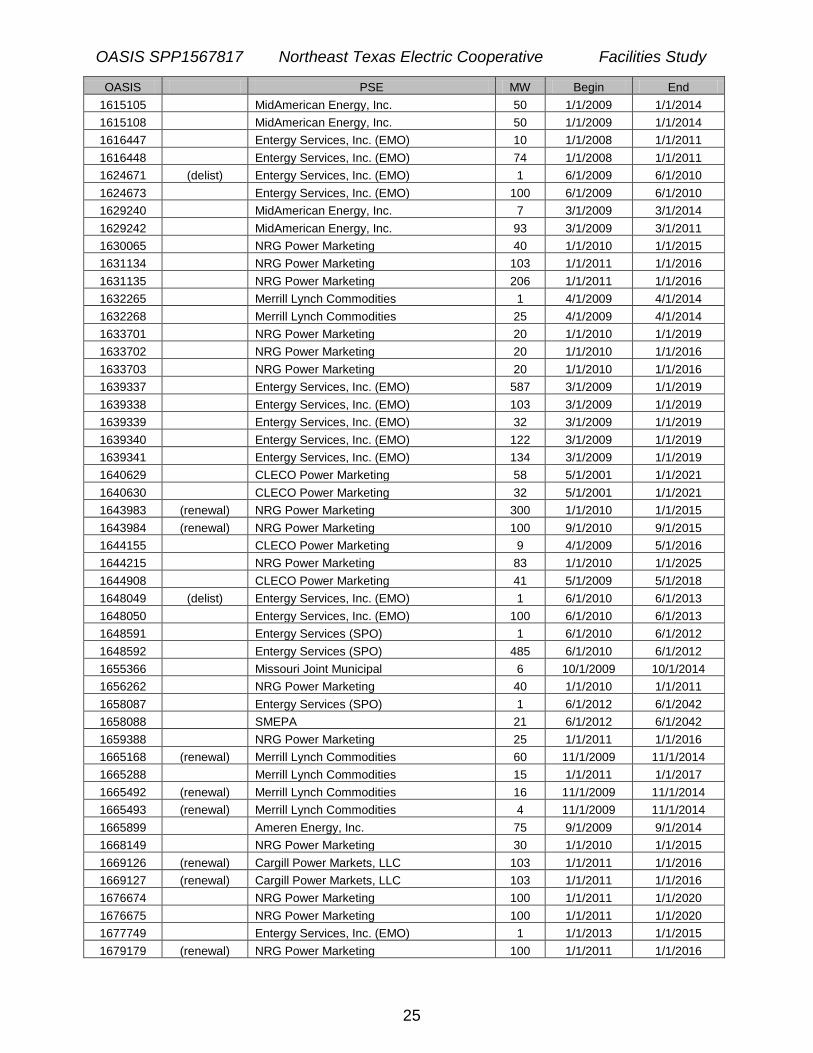
7. CONFIRMED RESERVATIONS
OASIS PSE MW Begin End
250778 (delist) Entergy Services, Inc. (EMO) 1 7/2/1998 7/1/2011
569011 Entergy Services, Inc. (EMO) 242 3/1/2000 1/1/2014
759196 Entergy Services, Inc. (EMO) 143 1/1/2001 1/1/2021
759294 East Texas Electric Cooperative 31 1/1/2001 1/1/2018
850304 Muni Energy Agcy of Miss 13 5/1/2001 6/1/2010
851493 Muni Energy Agcy of Miss 13 5/1/2001 6/1/2010
1096986 Tennessee Valley Authority 73 9/1/2003 9/1/2013
1099991 (renewal) City Water & Light, Jonesboro 83 1/1/2010 1/1/2016
1099997 (renewal) City Water & Light, Jonesboro 168 1/1/2010 1/1/2016
1105665 Entergy Services, Inc. (EMO) 236 2/1/2003 2/1/2016
1105666 Entergy Services, Inc. (EMO) 91 2/1/2003 2/1/2027
1105668 Entergy Services, Inc. (EMO) 77 2/1/2003 2/1/2027
1126821 Entergy Services, Inc. (EMO) 101 5/1/2004 5/1/2029
1151106 Entergy Services, Inc. (EMO) 20 6/1/2010 6/1/2029
1168061 Entergy Services, Inc. (EMO) 80 8/1/2004 2/1/2028
1168408 Entergy Services, Inc. (EMO) 247 8/1/2004 2/1/2028
1289686 (delist) Entergy Services, Inc. (EMO) 1 6/1/2007 6/1/2030
1294132 Entergy Services, Inc. (EMO) 526 1/1/2006 1/1/2035

OASIS SPP1567817 Northeast Texas Electric Cooperative Facilities Study
23
OASIS PSE MW Begin End
1309874 (renewal) East Texas Electric Cooperative 75 1/1/2009 1/1/2017
1309875 (renewal) East Texas Electric Cooperative 50 1/1/2009 1/1/2017
1309876 (renewal) East Texas Electric Cooperative 50 1/1/2009 1/1/2017
1328125 CLECO Power Marketing 35 1/1/2006 1/1/2011
1338849 Louisiana Energy & Power Authority 45 9/1/2005 9/1/2010
1356328 Muni Energy Agcy of Miss 40 6/1/2010 6/1/2040
1373643 City of Conway 25 3/1/2010 3/1/2040
1375299 Louisiana Generating LLC 11 3/1/2006 3/1/2013
1375300 Louisiana Generating LLC 8 3/1/2006 3/1/2011
1375301 Louisiana Generating LLC 5 3/1/2006 3/1/2011
1375559 CLECO Power LLC (Gen) 675 12/1/2006 12/1/2016
1380484 Osceola Light & Power 9 9/1/2009 9/1/2039
1381398 Constellation Energy Commodities Grp. 34 1/1/2006 1/1/2036
1381400 Constellation Energy Commodities Grp. 34 1/1/2006 1/1/2036
1381404 Constellation Energy Commodities Grp. 17 1/1/2006 1/1/2036
1381406 Constellation Energy Commodities Grp. 17 1/1/2006 1/1/2036
1383852 Arkansas Electric Cooperative Corp. 550 1/1/2007 1/1/2017
1384737 Louisiana Energy & Power Authority 13 9/1/2005 9/1/2010
1385158 NRG Power Marketing 13 10/1/20070 10/1/2027
1387272 CLECO Power LLC (Gen) 11 4/1/2006 4/1/2016
1422708 (delist) Entergy Services, Inc. (EMO) 1 1/1/2007 1/1/2027
1425495 East Texas Electric Cooperative 50 3/1/2010 3/1/2045
1437089 Arkansas Electric Cooperative Corp. 349 1/1/2007 1/1/2012
1440189 Arkansas Electric Cooperative Corp. 84 1/1/2008 1/1/2012
1440190 Arkansas Electric Cooperative Corp. 104 1/1/2008 1/1/2012
1442296 (renewal) NRG Power Marketing 103 1/1/2008 1/1/2011
1442453 NRG Power Marketing 320 6/1/2007 6/1/2026
1449495 Entergy Services, Inc. (EMO) 322 6/1/2009 6/1/2059
1456636 CLECO Power Marketing 10 10/1/2007 10/1/2012
1460876 Aquila Networks-MPS 75 3/1/2009 3/1/2029
1460878 Aquila Networks-MPS 75 3/1/2009 3/1/2029
1460879 Aquila Networks-MPS 75 3/1/2009 3/1/2029
1460881 Aquila Networks-MPS 75 3/1/2009 3/1/2029
1460898 Louisiana Energy & Power Authority 3 1/1/2009 1/1/2030
1460899 Louisiana Energy & Power Authority 5 1/1/2009 1/1/2030
1461442 Louisiana Energy & Power Authority 12 1/1/2009 1/1/2030
1464028 East Texas Electric Cooperative 168 1/1/2010 1/1/2040
1468113 Muni Energy Agcy of Miss 20 6/1/2011 6/1/2041
1470484 City of West Memphis 20 1/1/2011 1/1/2041
1470811 East Texas Electric Cooperative 186 1/1/2010 1/1/2040
1472304 (renewal) South Miss Electric Power Assoc. 75 6/1/2009 6/1/2011
1472315 South Miss Electric Power Assoc. 100 6/1/2010 6/1/2011
1477069 Entergy Services, Inc. (EMO) 10 11/1/2007 11/1/2037
1480164 Entergy Services, Inc. (EMO) 725 1/1/2005 9/1/2033
1483485 Entergy Services, Inc. (EMO) 100 1/1/2008 1/1/2011
1495910 Southwestern Electric 78 5/1/2010 5/1/2013
1498122 Constellation Energy Commodities Grp. 30 4/1/2012 4/1/2042
1498129 City of Conway 50 4/1/2012 4/1/2042
1499610 Entergy Services, Inc. (EMO) 300 1/1/2008 1/1/2038

OASIS SPP1567817 Northeast Texas Electric Cooperative Facilities Study
24
OASIS PSE MW Begin End
1500582 (delist) Entergy Services, Inc. (EMO) 1 1/1/2008 1/1/2038
1500584 (delist) Entergy Services, Inc. (EMO) 1 1/1/2008 1/1/2038
1514102 East Texas Electric Cooperative 29 1/1/2008 1/1/2017
1514104 East Texas Electric Cooperative 35 1/1/2008 1/1/2017
1514105 (delist) East Texas Electric Cooperative 1 1/1/2008 1/1/2017
1517005 (renewal) NRG Power Marketing 103 1/1/2011 1/1/2026
1521210 (renewal) NRG Power Marketing 5 9/1/2009 9/1/2010
1523070 (renewal) NRG Power Marketing 100 9/1/2009 9/1/2010
1523071 (renewal) NRG Power Marketing 100 1/1/2010 1/1/2011
1523072 (renewal) NRG Power Marketing 100 1/1/2010 1/1/2011
1525820 (renewal) NRG Power Marketing 3 7/1/2009 7/1/2014
1527816 Westar Energy 6 10/1/2007 10/1/2012
1530287 Empire District Electric 50 3/1/2010 3/1/2030
1530288 Empire District Electric 50 3/1/2010 3/1/2030
1531163 (renewal) NRG Power Marketing 103 7/1/2009 7/1/2010
1543574 (renewal) Cargill Power Markets, LLC 103 1/1/2010 1/1/2011
1546095 (delist) Entergy Services, Inc. (EMO) 1 1/1/2008 1/1/2011
1546108 (delist) Entergy Services, Inc. (EMO) 1 1/1/2011 1/1/2051
1552148 (delist) Entergy Services, Inc. (EMO) 1 1/1/2009 1/1/2014
1555122 (renewal) Constellation Energy Commodities Grp. 28 1/1/2009 1/1/2011
1555123 (renewal) Constellation Energy Commodities Grp. 22 1/1/2009 1/1/2011
1555124 (renewal) Constellation Energy Commodities Grp. 25 1/1/2009 1/1/2011
1555547 (renewal) Cargill Power Markets, LLC 103 1/1/2010 1/1/2011
1555717 (delist) East Texas Electric Cooperative 1 1/1/2010 1/1/2015
1555718 Entergy Services, Inc. (EMO) 158 1/1/2010 1/1/2015
1557220 (delist) Entergy Services, Inc. (EMO) 1 7/1/2009 7/1/2018
1557221 Entergy Services, Inc. (EMO) 520 7/1/2009 7/1/2018
1557602 (delist) East Texas Electric Cooperative 1 1/1/2009 1/1/2017
1564001 (renewal) Louisiana Energy & Power Authority 6 4/1/2009 4/1/2014
1564356 (renewal) NRG Power Marketing 5 9/1/2009 9/1/2025
1566302 NRG Power Marketing 300 1/1/2008 1/1/2013
1577552 (renewal) NRG Power Marketing 103 7/1/2009 7/1/2010
1577553 (renewal) NRG Power Marketing 103 1/1/2010 1/1/2011
1585225 (renewal) City of Prescott 22 4/1/2009 4/1/2039
1585239 (delist) Entergy Services, Inc. (EMO) 1 1/1/2009 1/1/2013
1585240 (delist) Entergy Services, Inc. (EMO) 1 1/1/2009 1/1/2013
1598022 (renewal) NRG Power Marketing 103 7/1/2010 7/1/2015
1598291 Entergy Services, Inc. (EMO) 206 6/1/2012 6/1/2042
1598885 (renewal) Morgan Stanley Commodities Group 102 1/1/2009 1/1/2014
1598886 (renewal) Morgan Stanley Commodities Group 102 1/1/2009 1/1/2014
1599383 Entergy Services, Inc. (EMO) 1 6/1/2009 6/1/2012
1599384 Entergy Services, Inc. (EMO) 485 6/1/2009 6/1/2012
1601111 Constellation 5 1/1/2010 1/1/2015
1602650 NRG Power Marketing 5 7/1/2010 7/1/2020
1604055 Westar Energy Generation and Marketing 15 6/1/2010 6/1/2015
1608189 (renewal) NRG Power Marketing 206 1/1/2010 1/1/2011
1611309 Entergy Services, Inc. (EMO) 804 1/1/2011 1/1/2058
1615102 (renewal) MidAmerican Energy, Inc. 50 1/1/2009 1/1/2014
1615103 MidAmerican Energy, Inc. 50 1/1/2009 1/1/2014
OASIS SPP1567817 Northeast Texas Electric Cooperative Facilities Study
25
OASIS PSE MW Begin End
1615105 MidAmerican Energy, Inc. 50 1/1/2009 1/1/2014
1615108 MidAmerican Energy, Inc. 50 1/1/2009 1/1/2014
1616447 Entergy Services, Inc. (EMO) 10 1/1/2008 1/1/2011
1616448 Entergy Services, Inc. (EMO) 74 1/1/2008 1/1/2011
1624671 (delist) Entergy Services, Inc. (EMO) 1 6/1/2009 6/1/2010
1624673 Entergy Services, Inc. (EMO) 100 6/1/2009 6/1/2010
1629240 MidAmerican Energy, Inc. 7 3/1/2009 3/1/2014
1629242 MidAmerican Energy, Inc. 93 3/1/2009 3/1/2011
1630065 NRG Power Marketing 40 1/1/2010 1/1/2015
1631134 NRG Power Marketing 103 1/1/2011 1/1/2016
1631135 NRG Power Marketing 206 1/1/2011 1/1/2016
1632265 Merrill Lynch Commodities 1 4/1/2009 4/1/2014
1632268 Merrill Lynch Commodities 25 4/1/2009 4/1/2014
1633701 NRG Power Marketing 20 1/1/2010 1/1/2019
1633702 NRG Power Marketing 20 1/1/2010 1/1/2016
1633703 NRG Power Marketing 20 1/1/2010 1/1/2016
1639337 Entergy Services, Inc. (EMO) 587 3/1/2009 1/1/2019
1639338 Entergy Services, Inc. (EMO) 103 3/1/2009 1/1/2019
1639339 Entergy Services, Inc. (EMO) 32 3/1/2009 1/1/2019
1639340 Entergy Services, Inc. (EMO) 122 3/1/2009 1/1/2019
1639341 Entergy Services, Inc. (EMO) 134 3/1/2009 1/1/2019
1640629 CLECO Power Marketing 58 5/1/2001 1/1/2021
1640630 CLECO Power Marketing 32 5/1/2001 1/1/2021
1643983 (renewal) NRG Power Marketing 300 1/1/2010 1/1/2015
1643984 (renewal) NRG Power Marketing 100 9/1/2010 9/1/2015
1644155 CLECO Power Marketing 9 4/1/2009 5/1/2016
1644215 NRG Power Marketing 83 1/1/2010 1/1/2025
1644908 CLECO Power Marketing 41 5/1/2009 5/1/2018
1648049 (delist) Entergy Services, Inc. (EMO) 1 6/1/2010 6/1/2013
1648050 Entergy Services, Inc. (EMO) 100 6/1/2010 6/1/2013
1648591 Entergy Services (SPO) 1 6/1/2010 6/1/2012
1648592 Entergy Services (SPO) 485 6/1/2010 6/1/2012
1655366 Missouri Joint Municipal 6 10/1/2009 10/1/2014
1656262 NRG Power Marketing 40 1/1/2010 1/1/2011
1658087 Entergy Services (SPO) 1 6/1/2012 6/1/2042
1658088 SMEPA 21 6/1/2012 6/1/2042
1659388 NRG Power Marketing 25 1/1/2011 1/1/2016
1665168 (renewal) Merrill Lynch Commodities 60 11/1/2009 11/1/2014
1665288 Merrill Lynch Commodities 15 1/1/2011 1/1/2017
1665492 (renewal) Merrill Lynch Commodities 16 11/1/2009 11/1/2014
1665493 (renewal) Merrill Lynch Commodities 4 11/1/2009 11/1/2014
1665899 Ameren Energy, Inc. 75 9/1/2009 9/1/2014
1668149 NRG Power Marketing 30 1/1/2010 1/1/2015
1669126 (renewal) Cargill Power Markets, LLC 103 1/1/2011 1/1/2016
1669127 (renewal) Cargill Power Markets, LLC 103 1/1/2011 1/1/2016
1676674 NRG Power Marketing 100 1/1/2011 1/1/2020
1676675 NRG Power Marketing 100 1/1/2011 1/1/2020
1677749 Entergy Services, Inc. (EMO) 1 1/1/2013 1/1/2015
1679179 (renewal) NRG Power Marketing 100 1/1/2011 1/1/2016

OASIS SPP1567817 Northeast Texas Electric Cooperative Facilities Study
26
OASIS PSE MW Begin End
1679181 (renewal) NRG Power Marketing 100 1/1/2011 1/1/2016
1682716 (renewal) NRG Power Marketing 206 1/1/2011 1/1/2012
1685869 (renewal) Muni Energy Agcy of Miss 19 1/1/2010 1/1/2018
1689499 Missouri Joint Municipal 3 9/1/2009 9/1/2014
1690613 NRG Power Marketing 25 1/1/2011 1/1/2016
1690834 NRG Power Marketing 50 4/1/2010 4/1/2011
1692555 American Electric Power 45 9/1/2000 1/1/2011
1692557 American Electric Power 6 9/1/2000 1/1/2011
1694305 Entergy Services (SPO) 15 5/1/2010 5/1/2020
1694306 Entergy Services (SPO) 30 5/1/2010 5/1/2020
73454527 Hope Water & Light 10 10/1/2009 10/1/2032
73457918 South Miss Electric Power Assoc. 180 10/1/2009 10/1/2014
73492252 NRG Power Marketing 28 1/1/2011 1/1/2016
73558673 (renewal) Merrill Lynch Commodities 11 1/1/2010 1/1/2011
73573797 (renewal) American Electric Power 45 1/1/2011 1/1/2029
73586299 (renewal) American Electric Power 6 1/1/2011 1/1/2029
OASIS SPP1567817 Northeast Texas Electric Cooperative Facilities Study
27
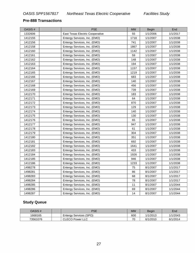
Pre-888 Transactions OASIS # PSE MW Begin End
1332606 East Texas Electric Cooperative 55 1/1/2006 1/1/2017
1412155 Entergy Services, Inc. (EMO) 1718 1/1/2007 1/1/2038
1412156 Entergy Services, Inc. (EMO) 741 1/1/2007 1/1/2038
1412158 Entergy Services, Inc. (EMO) 1867 1/1/2007 1/1/2038
1412160 Entergy Services, Inc. (EMO) 1142 1/1/2007 1/1/2038
1412161 Entergy Services, Inc. (EMO) 59 1/1/2007 1/1/2038
1412162 Entergy Services, Inc. (EMO) 148 1/1/2007 1/1/2038
1412163 Entergy Services, Inc. (EMO) 194 1/1/2007 1/1/2038
1412164 Entergy Services, Inc. (EMO) 1157 1/1/2007 1/1/2038
1412165 Entergy Services, Inc. (EMO) 1219 1/1/2007 1/1/2038
1412166 Entergy Services, Inc. (EMO) 683 1/1/2007 1/1/2038
1412167 Entergy Services, Inc. (EMO) 140 1/1/2007 1/1/2038
1412168 Entergy Services, Inc. (EMO) 456 1/1/2007 1/1/2038
1412169 Entergy Services, Inc. (EMO) 739 1/1/2007 1/1/2038
1412170 Entergy Services, Inc. (EMO) 183 1/1/2007 1/1/2038
1412171 Entergy Services, Inc. (EMO) 64 1/1/2007 1/1/2038
1412172 Entergy Services, Inc. (EMO) 870 1/1/2007 1/1/2038
1412173 Entergy Services, Inc. (EMO) 129 1/1/2007 1/1/2038
1412174 Entergy Services, Inc. (EMO) 140 1/1/2007 1/1/2038
1412175 Entergy Services, Inc. (EMO) 130 1/1/2007 1/1/2038
1412176 Entergy Services, Inc. (EMO) 65 1/1/2007 1/1/2038
1412177 Entergy Services, Inc. (EMO) 947 1/1/2007 1/1/2038
1412178 Entergy Services, Inc. (EMO) 61 1/1/2007 1/1/2038
1412179 Entergy Services, Inc. (EMO) 304 1/1/2007 1/1/2038
1412180 Entergy Services, Inc. (EMO) 351 1/1/2007 1/1/2038
1412181 Entergy Services, Inc. (EMO) 692 1/1/2007 1/1/2038
1412182 Entergy Services, Inc. (EMO) 1641 1/1/2007 1/1/2038
1412183 Entergy Services, Inc. (EMO) 433 1/1/2007 1/1/2038
1412184 Entergy Services, Inc. (EMO) 1926 1/1/2007 1/1/2038
1412185 Entergy Services, Inc. (EMO) 946 1/1/2007 1/1/2038
1412186 Entergy Services, Inc. (EMO) 1233 1/1/2007 1/1/2038
1498278 Entergy Services, Inc. (EMO) 75 8/1/2007 1/1/2017
1498281 Entergy Services, Inc. (EMO) 86 8/1/2007 1/1/2017
1498283 Entergy Services, Inc. (EMO) 68 8/1/2007 1/1/2017
1498284 Entergy Services, Inc. (EMO) 78 8/1/2007 1/1/2017
1498285 Entergy Services, Inc. (EMO) 11 8/1/2007 1/1/2044
1498286 Entergy Services, Inc. (EMO) 69 8/1/2007 1/1/2044
1498287 Entergy Services, Inc. (EMO) 14 8/1/2007 1/1/2044
Study Queue
OASIS # PSE MW Begin End
1668165 Entergy Services (SPO) 600 1/1/2013 1/1/2043
73561076 CLECO Power LLC 70 6/1/2010 6/1/2014

OASIS SPP1567817 Northeast Texas Electric Cooperative Facilities Study
28
8. ATTACHMENTS
A. Table of Acronyms
ACSR Aluminum Conductor Steel Reinforced ACSS Aluminum Conductor Steel Supported ADEQ Arkansas Department of Environmental Quality AFUDC Allowance for Funds Used During Construction ATC CCN
Available Transfer Capability Certificate of Convenience and Necessity
EES Entergy Control Area EHV Extra-High Voltage ICT Independent Coordinator of Transmission kV Kilo-Volt MCM (M) Thousand Circular Mils MVA Mega-Volt Amp MW Mega-Watt NOI Notice of Intent OASIS Online Access and Same-time Information System OATT Open Access Transmission Tariff POD Point of Delivery POR Point of Receipt SES Steam Electric Station SOC System Operations Center SHV Super High Voltage SW Switch Station TOC Transmission Operations Center

OASIS SPP1567817 Northeast Texas Electric Cooperative Facilities Study
29
B. One line Diagram – Grimes
One line diagrams for Grimes 345 and 138 kV below:

OASIS SPP1567817 Northeast Texas Electric Cooperative Facilities Study
30
C - Milestone schedule