transmission line magnetic field minimization … · transmission line magnetic field minimization...
TRANSCRIPT
TRANSMISSION LINE MAGNETIC FIELD MINIMIZATION
VIA PARTICLE SWARM OPTIMIZATION
MOHAMAD AMIRUL NIZAM BIN MOHAMED THARI
UNIVERSITI TEKNOLOGI MALAYSIA
TRANSMISSION LINE MAGNETIC FIELD MINIMIZATION
VIA PARTICLE SWARM OPTIMIZATION
MOHAMAD AMIRUL NIZAM BIN MOHAMED THARI
A project report submitted in partial fulfilment of the
requirements for the award of the degree of
Master of Engineering (Electrical - Power).
Faculty of Electrical Engineering
Universiti Teknologi Malaysia
JUNE 2014

iii
To my beloved
Mother,
Rahmah Abdul Rasid
To my wife and daughters,
Nordiah binti Abdul Hamid,
Amirah Humaira and Amirah Maisara
To my supervisor,
Prof Ir Dr Mohd Wazir bin Mustafa
To all my supportive members,
Thank for your support and sacrifices

iv
ACKNOWLEDGEMENT
Bismillahirrahmannirrahim, I would like to take this opportunity to express
my deepest gratitude to my project supervisor, Prof. Ir. Dr. Mohd Wazir bin Mustafa,
for his support and encouragement during the whole period of project study.
Gratitude and appreciation also to my mother, Rahmah Abd. Rasid, for her
encouragement and continuing support, without which, I would never have been able
to make it this far.
Also a lot of thanks to my wife Nordiah Abdul Hamid, and my daughters,
Amirah Humaira and Amirah Maisara, for their sacrifice and attentions along the
studies.
Finally, I would like to thank all my friends for their friendship and their
support, which make this journey a joyful one. Thanks.
v
ABSTRACT
Recently, many people fear about the radiation exposure from the
transmission line in Malaysia. There are very few people who can differentiate
between ionizing and non-ionizing radiation. "Radiation" from the high-voltage
transmission line consists of a magnetic field and electric field. In this project, the
magnetic field from transmission line was calculated using MATLAB programming.
The calculations are base above one meter from the ground and across the
transmission line. The new positions of conductors were determined using Particle
Swarm Optimization technique to get the minimum value of magnetic field. The
technique is represents the movement of organisms such as bird flock or fish school.
Particle swarm consists of 'n' particles and the position of each particle stand for the
potential solution in 'D' dimensional space. The particles change its condition
according to the following principles; to keep its inertia, to change the condition
according to its most optimist position, and to change the condition according to the
swarm’s most optimist position. The magnetic field was calculated with several
design of transmission line and then the new positions of conductors with lowest
magnetic field were determined. The results have been compared with Table 5.1 in
this report and found that it meets the magnetic field value at a voltage of 400kV. As
the magnetic field produced became lower, the magnetic field exposure to the public
nearby the transmission line also will be low. Hopefully, this will be useful for the
designers or engineers to design the lower exposure of magnetic field from the
transmission lines hence will be able to meet the safety limit exposure to the public.
vi
ABSTRAK
Kini, terdapat ramai yang bimbang mengenai pendedahan radiasi daripada
talian penghantaran di Malaysia. Masih lagi ramai yang tidak dapat membezakan
antara sinaran mengion dan sinaran tak mengion. "Sinaran" dari talian penghantaran
voltan tinggi terdiri daripada medan magnet dan medan elektrik. Di dalam projek ini,
medan magnet dari talian penghantaran dikira dengan menggunakan pengaturcaraan
MATLAB. Pengiraan adalah berdasarkan satu meter dari tanah dan merintangi talian
penghantaran tersebut. Kedudukan baru konduktor ditentukan menggunakan teknik
Pengoptimuman Kerumunan Zarah untuk mendapatkan nilai minimum medan
magnet. Teknik ini mewakili pergerakan organisma seperti kawanan burung atau
sekumpulan ikan. Kerumunan zarah ini terdiri daripada zarah 'n', dan kedudukan
setiap zarah mempunyai penyelesaian berpotensi dalam ruang dimensi 'D'. Zarah
berubah keadaan mengikut prinsip-prinsip berikut; untuk mengekalkan inersia, untuk
menukar keadaannya mengikut kedudukan yang paling optimis, dan untuk mengubah
keadaan pada kedudukan yang paling optimis dalam kerumunan zarah. Keputusan
kajian ini telah dibandingkan dengan Jadual 5.1 di dalam laporan ini dan didapati
ianya menepati nilai medan magnet pada voltan 400kV. Medan magnet dikira
mengikut beberapa reka bentuk talian penghantaran dan kemudian kedudukan baru
konduktor dengan medan magnet terendah ditentukan. Dengan medan magnet yang
dihasilkan menjadi lebih rendah, pendedahan medan magnet kepada orang ramai
berdekatan talian penghantaran juga akan menjadi rendah. Semoga ianya akan
berguna untuk perekabentuk atau jurutera untuk merekabentuk talian penghantaran
dengan pendedahan daripada medan magnet yang lebih rendah, oleh itu akan dapat
memenuhi had pendedahan kepada orang awam.
vii
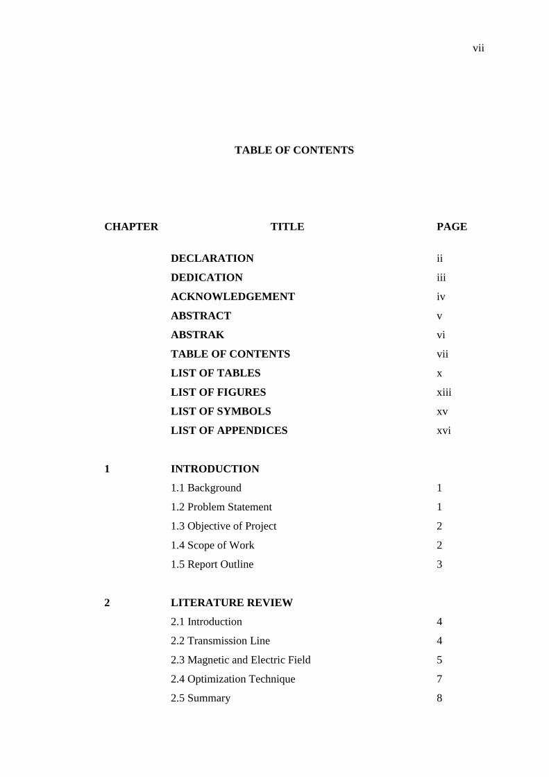
TABLE OF CONTENTS
CHAPTER TITLE PAGE
DECLARATION ii
DEDICATION iii
ACKNOWLEDGEMENT iv
ABSTRACT v
ABSTRAK vi
TABLE OF CONTENTS vii
LIST OF TABLES x
LIST OF FIGURES xiii
LIST OF SYMBOLS xv
LIST OF APPENDICES xvi
1 INTRODUCTION
1.1 Background 1
1.2 Problem Statement 1
1.3 Objective of Project 2
1.4 Scope of Work 2
1.5 Report Outline 3
2 LITERATURE REVIEW
2.1 Introduction 4
2.2 Transmission Line 4
2.3 Magnetic and Electric Field 5
2.4 Optimization Technique 7
2.5 Summary 8
viii
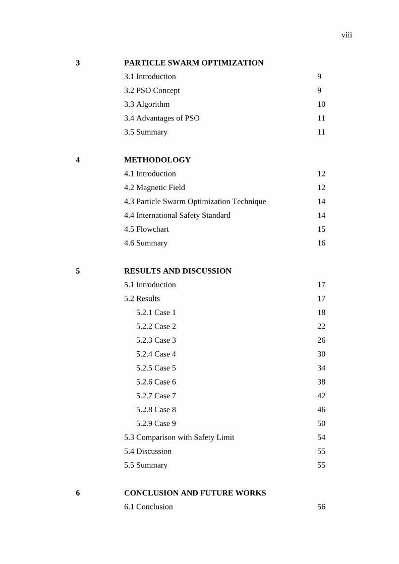
3 PARTICLE SWARM OPTIMIZATION
3.1 Introduction 9
3.2 PSO Concept 9
3.3 Algorithm 10
3.4 Advantages of PSO 11
3.5 Summary 11
4 METHODOLOGY
4.1 Introduction 12
4.2 Magnetic Field 12
4.3 Particle Swarm Optimization Technique 14
4.4 International Safety Standard 14
4.5 Flowchart 15
4.6 Summary 16
5 RESULTS AND DISCUSSION
5.1 Introduction 17
5.2 Results 17
5.2.1 Case 1 18
5.2.2 Case 2 22
5.2.3 Case 3 26
5.2.4 Case 4 30
5.2.5 Case 5 34
5.2.6 Case 6 38
5.2.7 Case 7 42
5.2.8 Case 8 46
5.2.9 Case 9 50
5.3 Comparison with Safety Limit 54
5.4 Discussion 55
5.5 Summary 55
6 CONCLUSION AND FUTURE WORKS
6.1 Conclusion 56

ix
6.2 Future Works 56
REFERENCES 58
Appendices 61
x
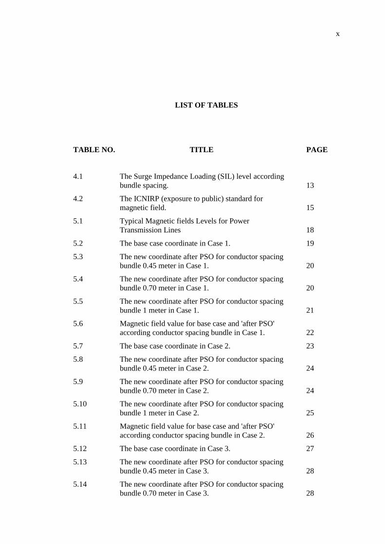
LIST OF TABLES
TABLE NO. TITLE PAGE
4.1 The Surge Impedance Loading (SIL) level according
bundle spacing. 13
4.2 The ICNIRP (exposure to public) standard for
magnetic field. 15
5.1 Typical Magnetic fields Levels for Power
Transmission Lines 18
5.2 The base case coordinate in Case 1. 19
5.3 The new coordinate after PSO for conductor spacing
bundle 0.45 meter in Case 1. 20
5.4 The new coordinate after PSO for conductor spacing
bundle 0.70 meter in Case 1. 20
5.5 The new coordinate after PSO for conductor spacing
bundle 1 meter in Case 1. 21
5.6 Magnetic field value for base case and 'after PSO'
according conductor spacing bundle in Case 1. 22
5.7 The base case coordinate in Case 2. 23
5.8 The new coordinate after PSO for conductor spacing
bundle 0.45 meter in Case 2. 24
5.9 The new coordinate after PSO for conductor spacing
bundle 0.70 meter in Case 2. 24
5.10 The new coordinate after PSO for conductor spacing
bundle 1 meter in Case 2. 25
5.11 Magnetic field value for base case and 'after PSO'
according conductor spacing bundle in Case 2. 26
5.12 The base case coordinate in Case 3. 27
5.13 The new coordinate after PSO for conductor spacing
bundle 0.45 meter in Case 3. 28
5.14 The new coordinate after PSO for conductor spacing
bundle 0.70 meter in Case 3. 28
xi
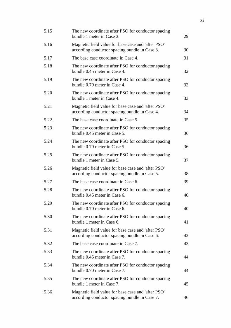
5.15 The new coordinate after PSO for conductor spacing
bundle 1 meter in Case 3. 29
5.16 Magnetic field value for base case and 'after PSO'
according conductor spacing bundle in Case 3. 30
5.17 The base case coordinate in Case 4. 31
5.18 The new coordinate after PSO for conductor spacing
bundle 0.45 meter in Case 4. 32
5.19 The new coordinate after PSO for conductor spacing
bundle 0.70 meter in Case 4. 32
5.20 The new coordinate after PSO for conductor spacing
bundle 1 meter in Case 4. 33
5.21 Magnetic field value for base case and 'after PSO'
according conductor spacing bundle in Case 4. 34
5.22 The base case coordinate in Case 5. 35
5.23 The new coordinate after PSO for conductor spacing
bundle 0.45 meter in Case 5. 36
5.24 The new coordinate after PSO for conductor spacing
bundle 0.70 meter in Case 5. 36
5.25 The new coordinate after PSO for conductor spacing
bundle 1 meter in Case 5. 37
5.26 Magnetic field value for base case and 'after PSO'
according conductor spacing bundle in Case 5. 38
5.27 The base case coordinate in Case 6. 39
5.28 The new coordinate after PSO for conductor spacing
bundle 0.45 meter in Case 6. 40
5.29 The new coordinate after PSO for conductor spacing
bundle 0.70 meter in Case 6. 40
5.30 The new coordinate after PSO for conductor spacing
bundle 1 meter in Case 6. 41
5.31 Magnetic field value for base case and 'after PSO'
according conductor spacing bundle in Case 6. 42
5.32 The base case coordinate in Case 7. 43
5.33 The new coordinate after PSO for conductor spacing
bundle 0.45 meter in Case 7. 44
5.34 The new coordinate after PSO for conductor spacing
bundle 0.70 meter in Case 7. 44
5.35 The new coordinate after PSO for conductor spacing
bundle 1 meter in Case 7. 45
5.36 Magnetic field value for base case and 'after PSO'
according conductor spacing bundle in Case 7. 46
xii
5.37 The base case coordinate in Case 8. 47
5.38 The new coordinate after PSO for conductor spacing
bundle 0.45 meter in Case 8. 48
5.39 The new coordinate after PSO for conductor spacing
bundle 0.70 meter in Case 8. 48
5.40 The new coordinate after PSO for conductor spacing
bundle 1 meter in Case 8. 49
5.41 Magnetic field value for base case and 'after PSO'
according conductor spacing bundle in Case 8. 50
5.42 The base case coordinate in Case 9. 51
5.43 The new coordinate after PSO for conductor spacing
bundle 0.45 meter in Case 9. 52
5.44 The new coordinate after PSO for conductor spacing
bundle 0.70 meter in Case 9. 52
5.45 The new coordinate after PSO for conductor spacing
bundle 1 meter in Case 9. 53
5.46 Magnetic field value for base case and 'after PSO'
according conductor spacing bundle in Case 9. 54
xiii
LIST OF FIGURES
FIGURE NO. TITLE PAGE
2.1 The magnetic field and Right-Hand Rule. 6
4.1 The graph of ICNIRP (exposure to public) for
magnetic field. 15
4.2 The flowchart of overall project. 16
5.1 The design of transmission line tower for Case 1. 18
5.2 Magnetic field value for base case design according
conductor spacing bundle in Case 1. 19
5.3 Magnetic field value after PSO according conductor
spacing bundle in Case 1. 21
5.4 The design of transmission line tower for Case 2. 22
5.5 Magnetic field value for base case design according
conductor spacing bundle in Case 2. 23
5.6 Magnetic field value after PSO according conductor
spacing bundle in Case 2. 25
5.7 The design of transmission line tower for Case 3. 26
5.8 Magnetic field value for base case design according
conductor spacing bundle in Case 3. 27
5.9 Magnetic field value after PSO according conductor
spacing bundle in Case 3. 29
5.10 The design of transmission line tower for case 4. 30
5.11 Magnetic field value for base case design according
conductor spacing bundle in Case 4. 31
5.12 Magnetic field value after PSO according conductor
spacing bundle in Case 4. 33
5.13 The design of transmission line tower for Case 5. 34
5.14 Magnetic field value for base case design according
conductor spacing bundle in Case 5. 35
xiv
5.15 Magnetic field value after PSO according conductor
spacing bundle in Case 5. 37
5.16 The design of transmission line tower for Case 6. 38
5.17 Magnetic field value for base case design according
conductor spacing bundle in Case 6. 39
5.18 Magnetic field value after PSO according conductor
spacing bundle in Case 6. 41
5.19 The design of transmission line tower for Case 7. 42
5.20 Magnetic field value for base case design according
conductor spacing bundle in Case 7. 43
5.21 Magnetic field value after PSO according conductor
spacing bundle in Case 7. 45
5.22 The design of transmission line tower for case 8. 46
5.23 Magnetic field value for base case design according
conductor spacing bundle in Case 8. 47
5.24 Magnetic field value after PSO according conductor
spacing bundle in Case 8. 49
5.25 The design of transmission line tower for Case 9. 50
5.26 Magnetic field value for base case design according
conductor spacing bundle in Case 9. 51
5.27 Magnetic field value after PSO according conductor
spacing bundle in Case 9. 53
5.28 Magnetic field value from all cases with ICNIRP
Public Safety Limit. 54
xv
LIST OF SYMBOLS
PSO - Particle Swarm Optimization
ICNIRP - International Committee on Non Ionizing Radiation
Protection
SIL - Surge Impedance Loading
MW - Megawatts
RLC - Resistance, Inductance, Capacitance
xvi
LIST OF APPENDICES
APPENDIX TITLE PAGE
A Magnetic Field Calculation 61
B Particle Swarm Optimization 63
C Magnetic Field Calculation After PSO 65
D Testfunction1 67
CHAPTER 1
INTRODUCTION
1.1 Background
The transmission line produce magnetic field. It is come from the current
flow in transmission line. Exposed to the magnetic field is believed to cause
biological effects to human [4]. Electric field is easier to absorb rather than magnetic
field. As electric field can absorb by the surrounding objects, magnetic field only can
blocked using special material but the cost is very high. Others method must be used
to reduce the magnetic field. There are several methods to reduce the value of
magnetic field such as mitigation loops [3]. Also, some of evolutionary programming
methods are used to get the minimum value. Hopefully with all these technique, the
engineers can design the transmission line with low magnetic fields produced.
1.2 Problem Statement
The concerning of public health effect from magnetic field exposure has
result this title to be selected. As the transmission line is used the 50Hz frequency, it
categorize in Extremely Low Frequency. The magnetic field is not easily to shielding
and for the transmission line case it is not the suitable technique to be used. Shielding
for magnetic field in this range of frequency require very thick and high permeability
material for make the shielding effective [6]. Some technique for example mitigation
2
loop is use to reduce the level of magnetic field [3], but in this project PSO is used to
arrange the location of transmission line to reduce the level of magnetic field.
1.3 Objectives of Project
The main objective of this project is to minimize the value of magnetic field
produced by transmission line. In order to ensure the achievement of the main
objective, several sub-objectives has to be divided:
i. to calculate the magnetic field from several design of transmission
line using MATLAB programming;
ii. to analyze the minimum value of magnetic field by arranging the
location of conductor using Particle Swarm Optimization (PSO)
technique;
iii. to compare the fields with international safety standards, either within
the permissible limit for the public or not.
1.4 Scopes of Work
The project is to simulate the value of magnetic field from the transmission
line using MATLAB programming. The simulation is based along 1 meter above the
ground [7]. Several design of transmission line will be identified. Then, the
arrangement of transmission line will be modified to have the minimum exposure of
magnetic field. The PSO technique will be used to get the new arrangement of
transmission line.
Next, the value of magnetic field will be compared with the permissible limit
for the public from the international safety standards. The rated voltage use only for
typical uncompensated 400kV line because of reference using for Surge Impedance
Loading (SIL) level in MW only for that rated voltage [11]. In this project also, the
calculations are not included the RLC effects for the transmission line.
3
1.5 Report Outline
This project report are consists of six chapters. In the Chapter 1, it discusses
on the problem statement, objective and the scope of this project.
Chapter 2, it will be discussed on the literature review of transmission line,
magnetic and electric fields and also about Optimization Technique. The Particle
Swarm Optimization will be discussed in the whole of Chapter 3.
In the Chapter 4, it will be discussed on methodology of this project. It is
include on determine the value of magnetic field, PSO and also the comparing on the
ICNIRP standard.
The results of the projects and discussions on the results are on Chapter 5, and
the last but not least, the conclusion on this project and recommendation for the
future works will discuss in the Chapter 6.
58
REFERENCES
[1] Tony Richard O. Almeida, Carlos F.R. Lemos Antunes, Magnetic Field
Computation Due to High Voltage Power Lines Using EasyMAG,
Departamento de Engenharia Electrotecnica ede Computadores, Universidade
de Coimbra, Portugal.
[2] J.M. Bakhashwain, M.H.Shwehdi, U.M Johar and A.A. Al-Naim, Magnetic
Fields Measurement and Evaluation of EHV Transmission Lines in Saudi
Arabia, Proceeding of the International Conference on Non-Ionizing
Radiation at UNITEN (ICNIR2003) Electromagnetic Fields and Our
Health, 20th - 22nd Oct 2003.
[3] Osama Elsayed Gouda, Adel Z. El Dein, Migitation of Magnetic Field under
Double- Circuit Overhead Transmission Line, TELKOMNIKA, Vol.
10, No. 8, pp. 2272-2284, December 2012.
[4] Magda Havas, Biological Effects of Low Frequency Electromagnetic Fields,
In: D. Clements-Croome (Ed.), Electromagnetic Environments and
Health in Buildings. Spon Press, London, pp. 535, 2004.
[5] Abu Izzeddin Salma, Berbari Kamal, Electromagnetic Field from Power
Lines, Final Year Project, Department of Electrical and Computer
Engineering, Faculty of Engineering and Architecture, 2006.
[6] M.S.H. Al Salameh, I.M. Nejdawi & O.A. Alani, Using the Nonlinear
Particle Swarm Optimization (PSO) Algorithm to Reduce the
Magnetic Fields from Overhead High Voltage Transmission Lines,
Department of Electrical Engineering, University of Science and
Technology, Irbid, Jordan, July 2010.
[7] Daniel Greenan, Calculation of the Magnetic Field Level in the Vicinity of a
400kV Transmission Line, Dublin Institute of Technology.
59
[8] Leandro dos Santos Coelho, Cezar Augusto Sierakowski, A Software tool for
teaching of particle swarm optimization fundamentals, Jan 2008.
[9] J.A. Brandao Faria, M.E Almeida, Accurate Calculation of Magnetic-Field
Intensity Due to Overhead Power Lines With or Without Mitigation
Loops With or Without Capacitor Compensation, IEEE, April 2007.
[10] M. S. H. Al Salameh and M. A. S. Hassouna, Arranging Overhead
Transmission Line Conductors Using Swarm Intelligence Technique to
Minimize Electromagnetic Fields, Jordan University of Science and
Technology, Jordan, 2010.
[11] R.N. Nayak, Y K Sehgal, and Subir Sen, EHV Transmission Line Capacity
Enhancement through Increase in Surge Impedance Loading Level, IEEE,
2006.
[12] Sunil Joseph P., C. Dinesh Balaji, Transmission Loss Minimization Using
Optimization Technique Based On PSO, Paavai Engineering College,
Namakkal, May-Jun 2013.
[13] International Commission on Non-Ionizing Radiation Protection, ICNIRP
Guidelines, for Limiting Exposure to Time- Varying Electric,
Magnetic, and Electromagnetic Fields (up to 300GHz), 1998.
[14] United States Environmental Protection Agency, Electric and Magnetic Field
(EMF) Radiation from Power Lines, April 2006.
[15] A.K.T Assis, J.E.A Ribeiro, A. Vannucci, The Field Concept of Faraday and
Maxwell.
[16] A.S. Farag, H. Hussain, I. Said, M. Abdel Kader, N. Abdul Rahman,
Electromagnetic Fields Associated with Transportation Systems in Malaysia,
Proceedings of the International Conference on Non-Ionizing Radiation at
UNITEN (ICNIR 2003), Electromagnetic Fields and Our Health, 20 - 22 Oct
2003.
[17] Qinghai Bai, Analysis of Particle Swarm Optimization Algorithm, Inner
Mongolia University of Nationalities, Tonglio, China, Feb 2010.
[18] Mohd Nasir Ahmad, Transmission Grid Planning, Tenaga Nasional Berhad,
Nov 2006.
[19] National Institute of Environmental Health Science and National Institute
of Health, EMF Electric and Magnetic Fields Associated with the Use of
Electric Power, June 2002.
60
[20] Andrew Blake, Comparison of the Efficiency of Deterministic and Stochastic
Algorithms for Visual Construction, IEEE Transactions on Pattern Analysis
and Machine Intelligence, Vol. 11, No. 1, Jan 1989.
[21] Bahadir Akbar, Abdullah Urkmez, The Parallel Resonance Impedance
Detection Method for Parameter Estimation of Power Line and Transformer
by using CSA, GA and PSO, Department of Electrical and Electronics
Engineering, Selçuk University, Konya, Turkey.
[22] National Cancer Institute at The National Institute of Health, Magnetic Field
Exposure and Cancer: Questions and Answers, USA.
[23] SPI Powernet, All About Magnetic and Electric Field from the Transmission
Lines, Melbourne.
[24] Anthony Ruth, Magnetic Field and Right Hand Rule, Academic Resource
Centre, Illinois Institute of Technology.
[25] G. Venter, Review of Optimization Techniques, Department of Mechanical
and Mechatronic Engineering, Stellenbosch University, South Africa.
[26] Daniel E. Marthaler, Chapter 2: An Overview of Mathematical Methods for
Numerical Optimization, GE Global Research: Industrial Internet Analytics,
San Ramon, USA, 2013.
[27] Ming-Hua Lin, Jung-Fa Tsai, and Chian-Son Yu, A Review of Deterministic
Optimization Methods in Engineering and Management, Shih Chien
University and National Taipei University of Technology,Taiwan, 2012.