transgranular stress corrosion cracking of 304l stainless
TRANSCRIPT
Boise State UniversityScholarWorksMaterials Science and Engineering FacultyPublications and Presentations Department of Materials Science and Engineering
10-1-2013
Transgranular Stress Corrosion Cracking of 304LStainless Steel Pipe Clamps in Direct UseGeothermal Water Heating ApplicationsMichael F. HurleyBoise State University
Christopher R. OlsonBoise State University
Logan J. WardBoise State University
Brian J. JaquesBoise State University
Kent A. JohnsonCity of Boise Geothermal Department
See next page for additional authors
NOTICE: this is the author’s version of a work that was accepted for publication in Engineering Failure Analysis. Changes resulting from the publishingprocess, such as peer review, editing, corrections, structural formatting, and other quality control mechanisms may not be reflected in this document.Changes may have been made to this work since it was submitted for publication. A definitive version was subsequently published in Engineering FailureAnalysis, Volume 33, (2013). DOI: 10.1016/j.engfailanal.2013.05.015.

AuthorsMichael F. Hurley, Christopher R. Olson, Logan J. Ward, Brian J. Jaques, Kent A. Johnson, Jonathan K.Gunnerson, and Darryl P. Butt
This article is available at ScholarWorks: https://scholarworks.boisestate.edu/mse_facpubs/164

1
Transgranular Stress Corrosion Cracking of 304L Stainless Steel Pipe Clamps in Direct Use Geothermal Water Heating
Applications
M. F. Hurley** Boise State University 1910 University Drive
Boise, Idaho 83725-2075
C. Olson Boise State University 1910 University Drive
Boise, Idaho 83725-2075
L. J. Ward Boise State University 1910 University Drive
Boise, Idaho 83725-2075
B. J. Jaques Boise State University 1910 University Drive
Boise, Idaho 83725-2075
K. Johnson City of Boise Geothermal Department
150 North Capitol Boulevard Boise, Idaho 83702
J. Gunnerson
City of Boise Geothermal Department 150 North Capitol Boulevard
Boise, Idaho 83702
D. P. Butt Boise State University 1910 University Drive
Boise, Idaho 83725-2075
**Corresponding author. Email: [email protected] Phone: 1-208-426-4075
Abstract
Direct use geothermal heating relies on heat extracted from naturally occurring geothermal water sources to provide heating needs for commercial and residential use. The city of Boise, Idaho maintains the largest district geothermal heating system in the United States, utilizing a source of geothermal water at 80°C. 304 Stainless steel (UNS S30400) pipe clamps are used throughout the system as repair seals and for new service connections. Occasionally unexpected fracture of the stainless steel clamps occurs with time-in-service periods as short as 1 year. A failure analysis was conducted, including visual, microstructural, compositional, and mechanical characterization, to determine the cause and source of the degradation. Cracking of the clamps was limited to localized regions with the remainder of the clamp unaffected. Branched, brittle cracks were observed in the failure region and exhibited transgranular propagation. Based on the temperature, available moisture, stress level, and type of material used it was determined that the likely cause of failure was neutral pH, dilute chloride-induced stress corrosion cracking. Based on this failure analysis, geothermal or other buried heated water systems must consider protective measures or more SCC-resistant materials to prevent susceptible conditions from developing, compared to conventional water systems, to ensure maximum lifetime performance.
Keywords: stainless steel; stress corrosion cracking; transgranular; geothermal; chloride.
This is an author-produced, peer-reviewed version of this article. The final, definitive version of this document can be found online at Engineering Failure Analysis, published by Elsevier. Copyright restrictions may apply. DOI: 10.1016/j.engfailanal.2013.05.015.
2
1. Introduction Direct use geothermal heating systems utilize moderate temperature (30-150°C) thermal wells and springs to provide heat for a number of applications [1]. Since the availability of direct-use heating is dependent on the accessibility and proximity to naturally occurring geothermal resources, typically the use of such systems is limited to regions with abundant geothermal resources. Direct use systems are in use worldwide and have been documented in at least 78 countries. In 2010 the five countries with the largest installed capacity include USA, China, Sweden, Germany and Japan, however Nordic European countries dominate on a per capita basis [2]. In the U.S. the viability of direct use is largely limited to the western states where geothermal sources are abundant and relatively close to the surface providing cost effective access. The direct use resources are only readily available to meet a small portion of global heating needs, however the low cost and very low environmental impact make it an attractive alternative to conventional heating sources. The city of Boise, Idaho maintains the largest and oldest direct use geothermal heating system in the US [3]. Currently the city system is the largest of four separate district heating systems within the region and provides heat for over 4.4 million square feet of government, commercial, and residential needs [4] with an expansion currently underway to be completed in 2013 that will potentially provide heat for an additional 2.2 million square feet [5].
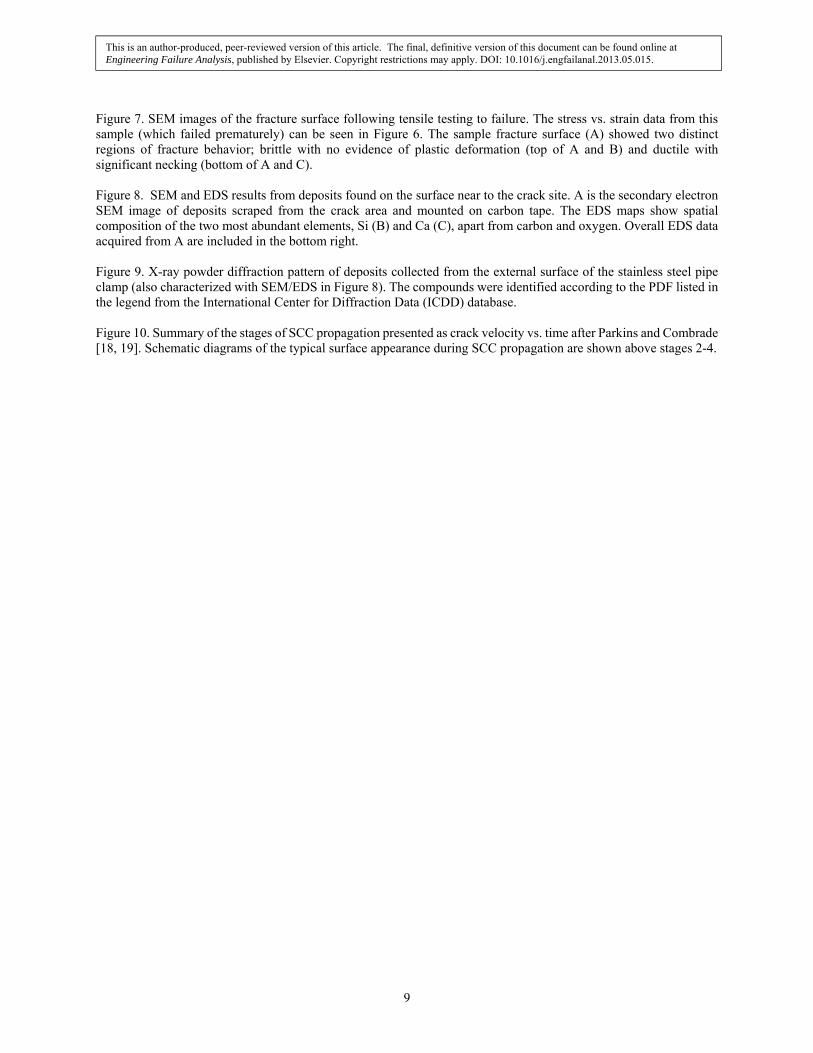
2. Background Geothermal water enters the Boise system at 80°C and a pressure of 55 psi from 800-2000 ft deep drill holes to 3 possible wells (of which 2 are currently in use). From the wells, geothermal water is then flowed through the system where heat is extracted for commercial and domestic heating systems, and then re-injected with an outlet temperature of 43°C and a pressure of 35 psi to the underground source. Re-injection of the extracted geothermal water after heat has been extracted replenishes water levels of the geothermal source and provides a means for longer-term sustainable use of the resource. The main service and customer distribution lines were constructed of 6-14” asbestos concrete with epoxy resin lined piping (AC pipe) and installed in 1983 with a total buried piping length of 16.7 miles. Piping is typically installed at a depth of 3-6 ft and surrounded by clean, backfill sand. Moreover, at valve stations underground vaults are also used to provide easier access for service. Recently, starting in 1999, non-metallic, insulated fiber reinforced composite (FRP) pipes have been installed and are being used exclusively in new construction. Periodic failures in the piping or carbon steel fittings are consistent with their long time in service and result in costly excavations and service downtime during repairs. Repairs where new pipe is spliced in or when new customer service connections are made utilize stainless steel pipe straps (Figure 1), typical of low temperature commercial and domestic water systems, and are the subject of this study. Generally, widespread reliable performance of the buried piping and components is aided by the use of clean backfill sand and relatively low corrosivity soil, possessing low moisture and high resistivity, typical of the high desert climate in the region. However, only sporadic failures of the stainless steel components have been observed and are typically limited to repair and/or service connection sites throughout the system [6, 7]. The absence of widespread system-wide failures or similar time-in-service periods suggest that the root cause is not directly attributable to the regional surrounding soil conditions of the buried piping or components. 2.1 Description of Components, Failures and Environment 2.1.1 Components A failure in the geothermal district heating system is typically detected by the leak presenting at the ground surface level and a drop in pressure. A repair is made by subsequent excavation to identify and gain access to the point of failure. Since 1988, roughly 4-8 excavations have been required for this direct use system annually. Of these, approximately 10% have involved failure of a stainless steel clamp component, and the time in service varies from 1 to 20 years. Stainless steel clamps are typically used to provide a seal following leak repair or a new service connection. The stainless steel clamp creates a seal around the geothermal line through stress applied via bolt tightening at the strap closure (Figure 1), and is separated from direct contact with the geothermal pipe by a 4 mm thick rubber liner and adhesive backing. The dimensions of the clamps are approximately 1 mm thick and 48 to 112 cm long (circumference), dependent on the pipe diameter, typically 6 to 14 inches. Independent chemical analysis of the stainless steel components indicated that the material used is 304 austenitic stainless steel (UNS S30400), significant additions to the alloy include 18% Cr and 8% Ni, mainly to increase corrosion resistance.
This is an author-produced, peer-reviewed version of this article. The final, definitive version of this document can be found online at Engineering Failure Analysis, published by Elsevier. Copyright restrictions may apply. DOI: 10.1016/j.engfailanal.2013.05.015.
3
2.1.2 Failures Figure 2, shows failed regions observed on stainless steel clamps collected after excavation. General, post-mortem examination of the failed stainless steel clamps show little indication of degradation aside from the failed region the component, Figure 2A,D,G. Failures typically occur far from welds or tensioning bolts, near the bottom (underside), and in most cases have shown small amounts of red or less frequently black corrosion products and/or mineral scale at the region of failure (Figure 2B,C,E,F). In a few cases, the bolts or region near the clamp closure have also failed or showed signs of degradation, but always in addition to the aforementioned strap failure. 2.1.3 Environment Ideally the geothermal water is completely contained within the piping system until it is re-injected to the source well, however, seeping from small leaks can provide adequate moisture to enable electrochemical activity, while also remaining undetectable via system pressure monitoring. Additionally, moisture in the soil may be present from the repaired leak which has previously saturated the surrounding backfill, surface irrigation, or storm drainage infrastructure in the urban setting. Consequently, the duration of wetness and location of moisture can be very difficult to ascertain and is dependent on the source or presence and period of any leak as well as leak rate. Local regions of heat, high humidity or wetting conditions may persist especially at the lowest point on the underside of the geothermal pipe where moisture may preferentially accumulate. A table of the chemical composition of the geothermal source water is included in Table 1. Moreover, at un-insulated junctions within buried vaults, persistent hot and humid conditions may exist due to seepage from the flowing geothermal water within the pipe and/or condensation on nearby, relatively cooler, surfaces. Moisture, which has permeated the backfill from the surrounding soil may also be present at the pipe surface. However regional nominal soil composition and very low annual precipitation (approximately 12 inches/yr), results in very low overall soil corrosivity. Soil resistivity values nearby to the geothermal system are typically around 10,000 Ω-cm (considered to be non-corrosive) with minor fluctuations depending on the season and location.1
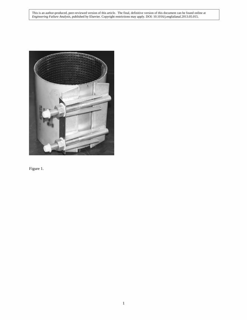
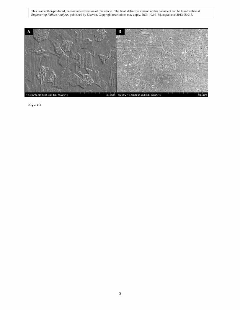
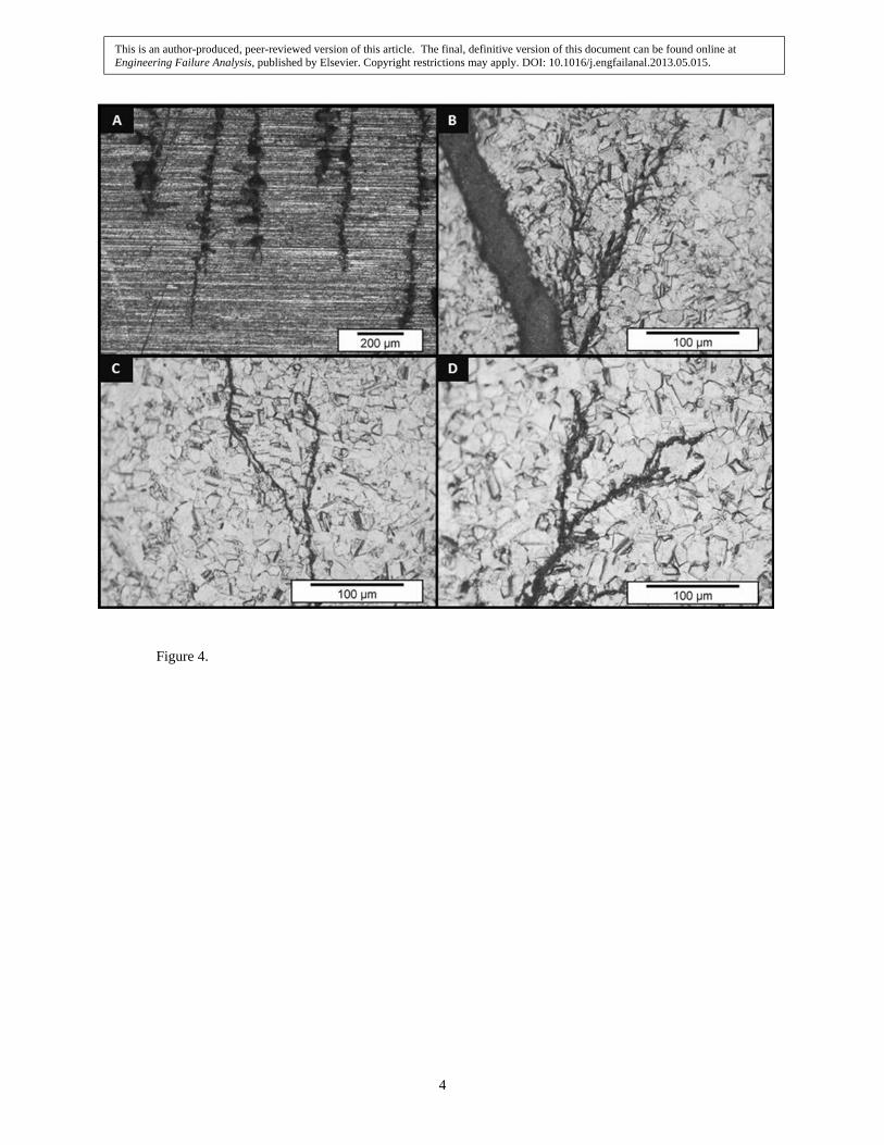
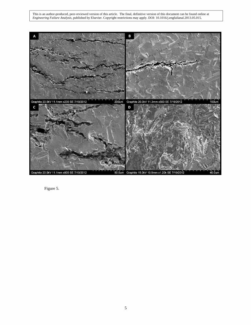
3 Failure Analysis A preliminary effort was made to confirm the expected clamp material specifications. The stainless steel straps were specified from the manufacturer as grade 304 and the composition was confirmed through independent chemical analysis. Representative pieces of the clamp from unaffected areas were sectioned, polished and etched to observe the microstructure, Figure 3. A general purpose metallographic etch (1:1:1, Water:Nitric acid:Hydrochloric acid) was used in all images where an etched surface is presented. The longitudinal and transverse grain structure indicated that the microstructure was consistent with annealed 304 stainless steel [8]. There was no indication of unwanted secondary phases or the presence of preferential or excessive inclusion particles observed in the sections characterized. The composition and microstructure verified the component specifications and therefore failure could not be linked to faulty materials or processing. 3.1 Visual Observations Visual characterization of the failed strap region showed that cracks propagated normal to the direction of applied stress, were brittle in appearance, and were accompanied by numerous smaller branched cracks (Figure 4). In addition, the observed cracks were limited to localized regions of the strap and the remaining area of the strap appeared unaffected. To better characterize the nature of cracking, samples were sectioned from cracked areas of the clamp and mounted in epoxy. Optical microscopy on the as-received surface revealed numerous branched cracks (Figure 4A) and polished, etched sections showed that cracking predominately propagated through grains, typically with numerous branches, Figure 4B-D. Moreover SEM characterization of polished and etched crack cross-sections showed populations of small, transgranular, branched cracks, Figure 5A-C. Some crack edges and tips also showed numerous, approximately 10 µm rounded features, likely anodic dissolution sites associated with an advancing crack. A representative crack face, shown in Figure 5D, had brittle, cleavage type appearance with no indication of ductile
1 Soil resistivity values graciously provided from an operator of a separate pipeline in the vicinity of the geothermal system.
This is an author-produced, peer-reviewed version of this article. The final, definitive version of this document can be found online at Engineering Failure Analysis, published by Elsevier. Copyright restrictions may apply. DOI: 10.1016/j.engfailanal.2013.05.015.

4
fracture. X-ray energy dispersive spectroscopy (EDS) performed on the crack face (Figure 5D) also indicated small volumes of Fe- and Cr-rich oxides were present (Table 2a-b.), consistent with the occurrence of localized corrosion. The presence of oxides or corrosion products was only observed on or adjacent to crack faces and no significant evidence of corrosion was seen elsewhere on the clamps. 3.2 Mechanical Testing To assess the degree of which the clamp was compromised, tensile testing was performed on samples machined from regions of the clamp that showed no evidence of cracking or degradation. The goal of this testing was to determine if the entire clamp was affected or if the cracked sections were the result of a specific local phenomena occurring at discreet areas of the clamp. Tensile testing was performed according to ASTM standard E8, and the resulting stress vs. strain behavior is presented in Figure 6. Mechanical testing results generally showed no evidence of degraded mechanical properties as the ductility and strength behavior agreed with that expected for 304 stainless steel [9]. Figure 6 shows results from 13 separate tests, of which 9 samples were prepared from failed clamps taken out of service and 4 samples were prepared from a new, unused clamp identical to those used in service. Although some test to test variability was observed, all samples regardless of service history, showed similar properties and were in agreement with expected 304 stainless steel mechanical properties. However, in one of the tensile tests premature failure occurred near the yield point (Figure 6). The anomaly sample failed near the grip area and SEM imaging of the fracture surface showed two different regions of fracture behavior (Figure 7). In this instance it is likely that a region of the sample contained a pre-existing flaw, too small to detect visually, at which brittle type fracture initially occurred and ductile fracture then proceeded across the remaining cross-section. The brittle portion of the fracture surface (Figure 7B) was similar in appearance to that in Figure 5D (which failed while in service) and had a dark, dull appearance due to oxides present on the surface with no evidence of plastic deformation preceding fracture. In contrast, the ductile fracture region (Figure 7C) was shiny, displayed a cup-and-cone morphology indicative of microvoid coalescence, and experienced significant necking prior to fracture. In summary, observations from mechanical testing showed that most of the in service clamp material was un-degraded, though areas on the samples near to failed regions may contain small cracks or colonies of cracks that are too small to detect visually. In additional to tensile testing, an investigation to determine the expected stress state of the clamp while in service was performed. A new clamp and pipe section, identical that those implemented in the Boise geothermal system, was procured (Figure 1). To determine the stress level, a 5 mm grid length, 120 Ω foil strain gauge was affixed to the clamp, orientated parallel to the direction of applied stress. The clamp was then placed around the pipe and tightened to the manufacture’s torque specifications, 80 ft/lbs. Resistance change measurements from the strain gauge were acquired during tightening and converted to amount of strain. The applied stress was determined to be 115 +/- 5 MPa, using the measured strain values and Young’s Modulus for 304 stainless steel [9]. Provided the clamps were installed according to specifications, the applied stress level of 115 MPa is approximately 53% of the minimum yield stress (215 MPa), for 304 stainless steel. This stress level provides adequate seal pressure around the pipe while safely below the yield stress of the clamp. 3.3 EDS/XRD of Deposits Near Crack Sites In some instances at regions on the clamp where cracking was observed, was typically also slight red or black staining (Figure 2) and/or flaky, white deposits. Since these deposits were limited to the cracked area and no evidence of corrosion damage was observed elsewhere on the sample, it can be concluded that the general environment which the clamps were exposed was not aggressive enough to sustain widespread active corrosion, though some localized corrosion likely occurred associated with cracking. The flaky white deposits near a crack site are likely the cause and/or result of the local environment which enabled the failure to occur at that region on the clamp. One plausible explanation is that at some areas an aggressive local solution chemistry evolved to bring the corrosion potential of the metal in that region into a window of stress corrosion cracking susceptibility [10]. Localized corrosion was likely coupled crack propagation and continued on newly created surfaces at the crack faces following crack advancement (see section 3.1). SEM/EDS and XRD was performed on the flaky white deposits found on the external surface of the clamp near crack sites for compositional and phase identification analysis and to determine the source and effect on the material, if any. Deposits were scraped from the clamp surface and mounted on carbon tape for SEM characterization, shown in Figure 8. Aside from carbon and oxygen the deposits were mainly a mix of separate Si-rich and Ca-rich compounds (Figures
This is an author-produced, peer-reviewed version of this article. The final, definitive version of this document can be found online at Engineering Failure Analysis, published by Elsevier. Copyright restrictions may apply. DOI: 10.1016/j.engfailanal.2013.05.015.
5
8B-C). Fluorine was also seen and typically appeared in the Ca-rich regions, as could be expected given the high affinity fluorine has to calcium. The relatively high fluorine abundance suggests that the water from which the deposits originated was the geothermal water, as it possessed a very high fluorine content (Table 1) compared to tap or rain water. In addition to EDS, XRD was also conducted on the deposits. Powder scraped from the clamp was ground with an agate mortar and pestle then mixed with acetone to properly fill and level the sample holder prior scanning. A Rigaku Miniflex 600 benchtop XRD was used and the diffraction pattern was collected using Cu-Kα radiation (λ = 0.1541 nm) produced at 40 kV and 15 mA in Bragg-Brentano geometry and a 1-dimensional D/teX detector at 3 °/min. The most prominent phases identified included; quartz (sand), calcium carbonate, albite, and calcium fluoride (Figure 9). EDS and supporting XRD data indicated that the deposits were likely a mix of backfill sand incorporated into mineral precipitates (Figures 8-9) during intermittent wetting from leaked geothermal water. Moreover, reduction of dissolved oxygen at cathodic sites will produce a slightly alkaline local surface chemistry that would also promote precipitation of mineral compounds, and would also explain why the deposits were typically found near crack sites. Such mineral deposits and adhered sand particles may also have provided an occluded region where conditions to support localized corrosion could preferentially develop, and subsequently act as crack initiation sites. Also, no evidence was seen of microbiological activity, such as black tubercules or extracellular matrix material [11] and the low SO4 content of the geothermal water is unlikely to support significant populations of sulfate reducing bacteria (Table 1). Hence, it is unlikely any degradation or SCC initiation sites were directly microbiological in origin.
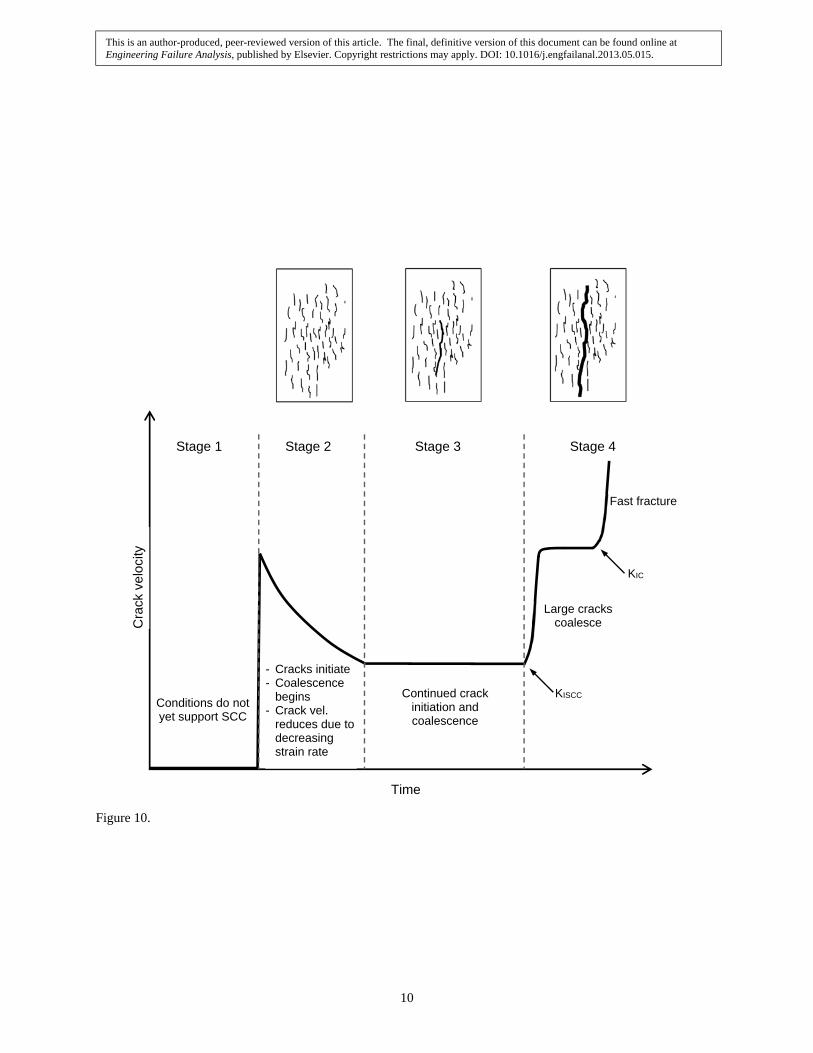
4 Discussion 4.1 Conditions for Stress Corrosion Cracking Environment, material, and threshold stress level are the three critical factors which simultaneously must be met in order for SCC to occur. All observations and characterization of the failed clamps indicate that failure was a result of chloride induced SCC. The clamps analyzed for this study showed brittle, branched, transgranular cracks that propagated normal to the applied stress. The occurrence of such phenomena is well documented in the literature for austenitic stainless steel exposed to moderate temperature, near neutral, dilute chloride waters [10, 12, 13]. For fully immersed samples it is generally considered that SCC is unlikely below 60°C and approximately 100 ppm Cl- [10]. However, under insulation or intermittent wet/dry cycles the situation is more deleterious and SCC has been observed at ambient temperature and chloride concentrations as low as 5 ppm [13, 14]. Under such conditions the actual chloride content is complicated by wet/dry cycles, deposits, or the presence of a tight gap at the pipe/clamp interface area, all of which can promote development of local regions with much higher chloride concentration than the surrounding environment. Although some potential exists for alternate SCC modes known to affect austenitic stainless steel such as metal sensitization, H2S, or hydrogen induced SCC [10, 15], these SCC triggers produce predominantly intergranular cracks, which were not seen in any of the samples analyzed for this investigation. The applied tensile stress around the circumference of the clamp while in-service was found to be approximately 115 MPa, from strain gauge testing. In very aggressive laboratory conditions no practical minimum stress level for SCC has been established [16]. However, compared to reported SCC threshold stress values of 80-100 MPa from testing in more similar environmental conditions [17], the in-service stress level is clearly sufficient to enable SCC. Crack growth rate could also be expected to increase with applied stress. Because the clamps are used for long-term, buried application, an actual crack growth rate is both difficult to ascertain and of little value since the crack growth period is very short compared to the intended service life. As the crack propagates, the stress applied via tightened bolt closure would quickly (relative to the initiation period) be relieved, resulting in a loss of seal pressure and need for repair. 4.2 Development of Failure Mechanism Once the three critical factors for SCC were met, cracking likely initiated and propagated until failure, according to the stages of SCC as proposed by Parkins, Figure 10 [18, 19]. During stage 1 the conditions for SCC have not been met yet or are in development. In order to progress to stage 2, moisture and chloride must also be present for electrochemical reactions to occur at local regions on the stainless steel clamp, bringing the corrosion potential in local areas on the clamp in to a region of SCC susceptibility. During stage 2 (Figure 10), electrochemical activity combined with the applied stress effect the cracking behavior of the normally ductile 304 stainless steel and colonies of short, brittle, transgranular cracks initiate (Figures 4-5). The strain associated with the formation and opening of these cracks
This is an author-produced, peer-reviewed version of this article. The final, definitive version of this document can be found online at Engineering Failure Analysis, published by Elsevier. Copyright restrictions may apply. DOI: 10.1016/j.engfailanal.2013.05.015.

6
provides some stress relief resulting in a crack velocity that decreases with time. During stage 3, cracks continue to initiate and propagate and favorably oriented cracks coalesce into larger cracks. Once a crack propagates to the critical length, the crack enters stage 4. During stage 4 large cracks coalesce and crack velocity increases dramatically. During stage 4, crack opening becomes so large that the applied stress from the tightened bolts is decreased, making the clamp pipe seal ineffective and allowing geothermal water to leak out unimpeded. Once the seal on the outside of the pipe is lost the internal pressure will drop as geothermal water is pushed out, at this point failure will finally be able to be detected via presence of surfacing geothermal water. Predicting time to failure is very difficult since stage 1 may last many years depending on the source and frequency of wetness. Three likely potential sources of moisture would produce widely varied stage 1 durations, for example:
Saturated soil from a previous leak or active seepage of geothermal water from a buried pipe defect or junction would likely give a short stage 1 duration, dependent on the amount of moisture present and/or frequency of a leak (see section 3.3).
Boldly exposed stainless steel components in an underground vault would encounter moisture from humid conditions in the buried vault from the time of placement. Compared to unheated water systems, the elevated temperature from flowing geothermal water and vault humidity can create conditions favorable for SCC.
If the pipe and components are leak free, moisture from the surrounding soil may eventually permeate
backfill to enable conditions for SCC to develop, depending on the soil resistivity and corrosivity. This scenario would likely yield the longest time to SCC initiation, if at all depending on the regional soil composition and seasonal precipitation (see section 2.1.3).
It is likely that once the conditions for stage 2 are met, failure occurs relatively quickly, perhaps on the order of weeks or months [10]. The conditions resulting in the failure investigated in this study were sufficient to cause stress corrosion cracking though the temperature, conservatively 70°C, and chloride content (10 ppm) and are near the lower limits of reported susceptibility [10, 14]. Observations from the failure analysis indicated that moisture was present and the composition of mineral deposits near the crack site suggested that moisture may have (at least partially) originated from the geothermal water from within the service line. However, given the range of time-to-failure and location of the stainless steel clamps observed in the last 20 years it is also possible that SCC initiation in some occurrences may be attributed to a number of other potential moisture sources. 4.3 Materials Selection All common 300 series austenitic stainless steels are known to be susceptible to SCC in dilute, near neutral, chloride environments. However, SCC susceptibility is strongly dependent on alloy microstructure and composition. Duplex and Ferritic stainless steels have much greater SCC resistance and Ni and Mo content have the largest effect on SCC susceptibility for austenitic steels. For austenitic stainless steels Ni content between 10-25% provides the lowest SCC resistance, though Ni content above 32% or Mo above 6% renders the alloy resistant[10]. Suggested alternate materials with much higher SCC resistance than 304 stainless steel include super austenitic stainless steels possessing greater than 6% Mo such as UNS N08367 and duplex stainless steels such as 2205 (UNS S32205), and should be considered to replace 304 stainless steel piping components for this and similar applications. Other mitigation options for buried pipe repair could be considered since many coating schemes have been developed for other buried pipe applications. However, the effectiveness of these methods is highly dependent on installation procedure and do not offer the same level of protection that can be expected with informed alloy selection.
This is an author-produced, peer-reviewed version of this article. The final, definitive version of this document can be found online at Engineering Failure Analysis, published by Elsevier. Copyright restrictions may apply. DOI: 10.1016/j.engfailanal.2013.05.015.

7
5 Conclusions Premature failures of 304 stainless steel clamps used in a buried direct-use geothermal system in Boise, Idaho have been investigated. To avoid further costly excavations and repairs, a failure analysis was conducted to determine the cause of failure and provide insight on how to avoid future failures, both in the system considered and any other applications with similar service conditions found elsewhere. Clamp failures resulted from the propagation of branched cracks normal to the direction of applied stress and were typically located near the lowest point on the pipe clamp, where moisture would be expected to preferentially accumulate. The failure mode was determined to be chloride induced stress corrosion cracking. Direct-use geothermal heating is a relatively small, but growing market largely due to its low carbon footprint and abundant low cost heat. Since the composition and temperature of the water used may cause susceptibility to failure modes not encountered with conventional low-temperature water systems, SCC resistant materials should be considered for use in existing and new direct-use geothermal heating systems.
6 Acknowledgments This work was performed in and supported by the Advanced Materials Laboratory at Boise State University. The City of Boise Geothermal Department provided access to the geothermal system, samples for testing and analysis, and volunteered support and consultation of the work throughout. Brandon Croy at Intermountain Gas graciously provided regional soil resistivity data.
7 References [1] P.J. Lineau, Introduction, in: J.W. Lund (Ed.), Geothermal Direct-Use Engineering and Design Guidebook, Geo-Heat Center, Klamath Falls, OR, 1998. [2] J.W. Lund, D.H. Freeston, T.L. Boyd. Direct Utilization of Geothermal Energy 2010 Worldwide Review. Geothermics. 40 (2011) 159-80. [3] R.G. Bloomquist, Geothermal Direct Use/Cogeneration and Co-Production, Presented at: International Centre for Science and High Technology of the United Nations Industrial Development Organization (ICS-UNIDO), Trieste, Italy, Dec. 10-12, 2008. [4] U.S.DOE, Geothermal Technologies Program: Direct Use, Pub. No. DOE/GO-102004-1957, National Renewable Energy Laboratory, Washington, D.C., 2004. [5] U.S. DOE, Environmental Assessment: Geothermal Expansion to Boise State University, Boise, Idaho, Pub. No. DOE/EA-1763, U.S. Dept. of Energy, Golden, Colorado, 2010. [6] K.A. Johnson, J.N. Gunnerson. Personal communication, City of Boise Geothermal System Managers, 2012-13. [7] R.L. Miller, Corrosion Engineering in the Utilization of the Raft River Geothermal Resource, ANCR 1318 Category: UC-66Geothermal Energy TID-4500, R64. Energy Research and Development Administration Idaho Operations Office, Contract: E(10-1)-1375., 1976. [8] G.F. VanderVoort. ASM Handbook, Vol. 9 - Metallography and Microstructures. ASM International, Materials Park, OH, 2008. [9] R. Steiner. ASM Handbook, Vol. 1 - Properties and Selection: Irons, Steels, and High-Performance Alloys. ASM International, Materials Park, OH, 2008. [10] J.A. Sedriks. Corrosion of Stainless Steels. 2nd Edition ed. Wiley, New York, 1996. [11] B.J. Little, J.S. Lee. Microbiologically Influenced Corrosion. Wiley-Interscience, Hoboken, N.J., 2007. [12] L.J. Korb. ASM Handbook, Vol. 13 - Corrosion. ASM International, Metals Park, Ohio, 2008. [13] D.R. McIntyre. Experience Survey, Stress Corrosion Cracking of Austenitic Stainless Steels in Water. The Materials Institute of the Chemical Process Industries, Columbus, Ohio, 1987. [14] T. Marshall, W.R. Braithwaite, Corrosion Control in Geothermal System, in: H.C.H. Armstead (Ed.), Geothermal Energy: Review of Research and Development, UNESCO, Paris, France, 1977, pp. 151-9. [15] D.A. Jones. Principles and Prevention of Corrosion. 2nd Edition ed. Prentice Hall, Upper Saddle River, N.J., 2005. [16] J.E. Truman. Methods Available for Avoiding Stress Corrosion Cracking of Austenitic Stainless Steels in Potentially Dangerous Environements. Iron and Steel Institute, ISI Publication 117, 1969. [17] S.R. Lampman. ASM Handbook, Vol. 19 - Fatigue and Fracture. ASM International, Materials Park, OH, 1996. [18] P. Combrade, Stress Corrosion Cracking in Low Temperature Environments, Presented at: Stress Corrosion Cracking in Nuclear Systems, INEST Workshop, Idaho Falls, Id., June 2010, A.N.T. International, 2010. [19] R.N. Parkins. Factors Influencing Stress Corrosion Crack Growth Kinetics. Corrosion. 43 (1987) 130-9.
This is an author-produced, peer-reviewed version of this article. The final, definitive version of this document can be found online at Engineering Failure Analysis, published by Elsevier. Copyright restrictions may apply. DOI: 10.1016/j.engfailanal.2013.05.015.

8
Table 1. Chemical analysis and temperature of the geothermal water used throughout the Boise direct-use district heating system.
Element: Al Ag As B Ba Be Bi Ca Cd Cl Co
mg/l: 0.01 <0.02 <0.05 0.14 <0.20 <0.02 0.01 2 <0.02 10 <0.02
Element: CO3 Cr Cu F Fe Hg K Li Mg Mn Na
mg/l 4 <0.02 0.08 18 <0.01 <0.02 1.6 0.05 0.05 <0.02 100
Element: Ni Pb SiO2 Sn SO4 Sr Ti V Zn Zr H2S
mg/l: 0.02 <0.02 160 <0.02 23 0.02 <0.02 <0.10 <0.02 <0.10 Tr.
pH = 8.2
Temp (°C) = 80
Total Dissolved Solids (ppm) = 290 Table 2a-b. EDS analysis from SEM characterization of the crack face surface. Results were obtained from a region nearby to that shown in Figure 5d and are the average of 3 spectra. Generally the results were either Cr rich (Table 2a) or Fe rich (Table 2b).
Figure Captions Figure 1. Image of a new 304 stainless steel pipe repair clamp identical to those studied in this investigation. Once a leak in the geothermal system has been excavated and repaired the pipe clamp is placed and sealing pressure is applied via bolt tightening. Figure 2. Pictures of three cracked geothermal pipe clamps (A, D, G), as observed following excavation of the geothermal line to obtain failed parts. Corresponding close-up images of typical failed regions are shown in images B,C,E,F,H, and I. Figure 3. SEM microstructure images of the longitudinal (A) and transverse (B) polished and etched sections of a failed 304 stainless steel geothermal pipe clamp. Figure 4. Optical (A) and scanning electron (B-D) micrographs of crack sites on a 304 stainless steel pipe clamp that failed in service. Figure 5. SEM images of cracks sites (A-C) on geothermal pipe clamps. Samples in images A-C were polished and etched prior to imaging. D is an image of the typical crack face appearance. Figure 6. Results from mechanical testing from tensile test samples machined from both new (un-used, seen in Figure 1) and failed 304 stainless steel (as seen in Figure 2) pipe repair clamps. One sample failed prematurely at a total strain of approximately 0.09.
a. Element: C O Si Cr Fe Ni Na, S, Cl, Ca, Mn Avg. wt%: 16 46 2.0 22 11 1.2 < 1 Std. Dev.: 3.6 8.2 1.2 5.5 2.0 0.3
b. Element: C O Cr Fe Ni Si, S, Mn Avg. wt%: 18 38 6.9 32 2.9 < 1 Std. Dev.: 1.7 1.6 2.2 2.8 0.8
This is an author-produced, peer-reviewed version of this article. The final, definitive version of this document can be found online at Engineering Failure Analysis, published by Elsevier. Copyright restrictions may apply. DOI: 10.1016/j.engfailanal.2013.05.015.
9
Figure 7. SEM images of the fracture surface following tensile testing to failure. The stress vs. strain data from this sample (which failed prematurely) can be seen in Figure 6. The sample fracture surface (A) showed two distinct regions of fracture behavior; brittle with no evidence of plastic deformation (top of A and B) and ductile with significant necking (bottom of A and C). Figure 8. SEM and EDS results from deposits found on the surface near to the crack site. A is the secondary electron SEM image of deposits scraped from the crack area and mounted on carbon tape. The EDS maps show spatial composition of the two most abundant elements, Si (B) and Ca (C), apart from carbon and oxygen. Overall EDS data acquired from A are included in the bottom right. Figure 9. X-ray powder diffraction pattern of deposits collected from the external surface of the stainless steel pipe clamp (also characterized with SEM/EDS in Figure 8). The compounds were identified according to the PDF listed in the legend from the International Center for Diffraction Data (ICDD) database. Figure 10. Summary of the stages of SCC propagation presented as crack velocity vs. time after Parkins and Combrade [18, 19]. Schematic diagrams of the typical surface appearance during SCC propagation are shown above stages 2-4.
This is an author-produced, peer-reviewed version of this article. The final, definitive version of this document can be found online at Engineering Failure Analysis, published by Elsevier. Copyright restrictions may apply. DOI: 10.1016/j.engfailanal.2013.05.015.
1
Figure 1.
This is an author-produced, peer-reviewed version of this article. The final, definitive version of this document can be found online at Engineering Failure Analysis, published by Elsevier. Copyright restrictions may apply. DOI: 10.1016/j.engfailanal.2013.05.015.

2
Figure 2.
This is an author-produced, peer-reviewed version of this article. The final, definitive version of this document can be found online at Engineering Failure Analysis, published by Elsevier. Copyright restrictions may apply. DOI: 10.1016/j.engfailanal.2013.05.015.
3
Figure 3.
This is an author-produced, peer-reviewed version of this article. The final, definitive version of this document can be found online at Engineering Failure Analysis, published by Elsevier. Copyright restrictions may apply. DOI: 10.1016/j.engfailanal.2013.05.015.
4
Figure 4.
This is an author-produced, peer-reviewed version of this article. The final, definitive version of this document can be found online at Engineering Failure Analysis, published by Elsevier. Copyright restrictions may apply. DOI: 10.1016/j.engfailanal.2013.05.015.
5
Figure 5.
This is an author-produced, peer-reviewed version of this article. The final, definitive version of this document can be found online at Engineering Failure Analysis, published by Elsevier. Copyright restrictions may apply. DOI: 10.1016/j.engfailanal.2013.05.015.

6
Figure 6.
This is an author-produced, peer-reviewed version of this article. The final, definitive version of this document can be found online at Engineering Failure Analysis, published by Elsevier. Copyright restrictions may apply. DOI: 10.1016/j.engfailanal.2013.05.015.

7
Figure 7.
This is an author-produced, peer-reviewed version of this article. The final, definitive version of this document can be found online at Engineering Failure Analysis, published by Elsevier. Copyright restrictions may apply. DOI: 10.1016/j.engfailanal.2013.05.015.

8
Figure 8.
A B
C
This is an author-produced, peer-reviewed version of this article. The final, definitive version of this document can be found online at Engineering Failure Analysis, published by Elsevier. Copyright restrictions may apply. DOI: 10.1016/j.engfailanal.2013.05.015.

9
Figure 9.
This is an author-produced, peer-reviewed version of this article. The final, definitive version of this document can be found online at Engineering Failure Analysis, published by Elsevier. Copyright restrictions may apply. DOI: 10.1016/j.engfailanal.2013.05.015.
10
Figure 10.
Stage 1 Stage 2 Stage 3 Stage 4
Conditions do not yet support SCC
- Cracks initiate- Coalescence
begins - Crack vel.
reduces due to decreasing strain rate
Continued crack initiation and coalescence
Large cracks coalesce
Fast fracture
KISCC
KIC
Time
Cra
ck v
elo
city
This is an author-produced, peer-reviewed version of this article. The final, definitive version of this document can be found online at Engineering Failure Analysis, published by Elsevier. Copyright restrictions may apply. DOI: 10.1016/j.engfailanal.2013.05.015.