transformers - expert-trafo.de · over and above, actuate master switch anyway! operating manual...
TRANSCRIPT

Operation Manual Heating Transformers 2011
Operating Manual
Heating Transformers
Tra
nsfo
rm
ers

Operating Manual
Transformers for Heating Technology
Table of Contents
1
Table of Contents
1 General 3
2 Notes on Safety 4
2.1 General Remarks ............................................................................................ 4
2.2Protection Against Direct and Indirect Contact with Electrically Conductive Parts . 5
2.2.1 Protection Against Direct Contact ................................................................... 5
2.2.2 Protection Against Indirect Contact in Case of Fault ....................................... 6
2.3 Protection from Electromagnetic Field Influences ........................................... 6
3 Technical Data 8
3.1 General ........................................................................................................... 8
3.2 Information on the type designation plate ....................................................... 8
4 Usage As Specified 10
4.1 Application Fields for Transformers .............................................................. 10
4.2 Operating Transformers at Other Mains Frequencies ................................... 11
4.3 Power Control Requirements ........................................................................ 12
5 Transformers Set-up and Function 13
5.1 Transformer Set-up ....................................................................................... 13
5.2 Subcircuits .................................................................................................... 15
5.2.1 Temperature Monitoring ............................................................................... 15
5.2.2 Current-measuring Coils ............................................................................... 16
6 Transportation and Storage 17
6.1 Transportation .............................................................................................. 17
6.2 Storage ......................................................................................................... 19
7 Installation, Electrical Connection and Commissioning 20
7.1 Mounting and Electrical Installation .............................................................. 20
7.2 Permissible Environmental Conditions ......................................................... 22
8 Notes on Operation of Transformers 23
8.1 Cooling Water Quality ................................................................................... 23
8.2 Cooling Water Quantity, Cooling Circuit Differential Pressure ...................... 24
9 Inspection and Maintenance 26
9.1 Primary and Secondary Terminals ................................................................ 26

Operating Manual
Transformers for Heating Technology
Table of Contents
2
9.2 Cooling circuit ............................................................................................... 26
10 Standards and Regulations 28

Operating Manual
Transformers for Heating Technology
General
3
1 General
Besides technical description of the product, the Operating Manual “Transformers for
Heating Technology” contains important information about handling, transportation,
assembly, and installation of EXPERT transformers and components in order to
ensure utmost safety both for man and machine and proper function.
Product use as directed in accordance with the following guidelines of the European
Union:
2006/95/EEC Electrical Equipment for Use Within Certain Voltage Limits (Low-voltage
Guideline)
2004/108/EEC Electromagnetic Compatibility (EMC Guideline)
89/392/EEC Machine Safety (Machine Guideline)
Beyond that the national regulations for erection and commissioning of electrotechnical
installations and the current safety regulations need to be observed.
The user shall receive necessary notes on safety in the following (see section 2).
The Operating Manual addresses the following user groups:
- Project planning and design staff
- Installation and commissioning personnel
- Maintenance and repair staff
- Transportation and storage staff

Operating Manual
Transformers for Heating Technology
Notes on Safety
4
2 Notes on Safety
2.1 General Remarks
Flawless and safe operation presupposes proper transportation, professional
storage, assembly, and installation as well as careful handling and maintenance.
The transformers are meant for incorporation in machines and installations in
commercial areas. The specific safety instructions and regulations need to be
observed for the application in hand.
Transformer operation is only permissible in combination with effective protective
measures against touching conducting parts in case of fault. This also applies to
short-time operation for check and test purposes.
Prior to switching on the transformer, live parts must be safely covered in order to
prevent accidental contact.
Before commencing installation or maintenance work, the machine or system must
be placed into a condition that allows safe work (e.g. normal position).
The part of machine or installation to be worked on shall be disconnected from the
supply. Transformers may have inverse voltages under certain conditions. Isolate
primary and secondary side in such cases. Beware of dangerous moving parts from
adjoining parts of the installation. With such hazards present, neighboring parts of the
installation need to be isolated too.
Caution: Power modules on semiconductor basis (thyristors, IGBTs, etc.) do not realize
electrical isolation of the circuit even when their driving was switched off! Over and
above, actuate master switch anyway!

Operating Manual
Transformers for Heating Technology
Notes on Safety
5
Secure switches that have been used for isolation against accidental reclosure. Mark
equipment with a danger sign, e.g. “DO NOT SWITCH ON! – Repair work in progress –
“ stating period of repair and name of responsible employee.
Verify all-pole safe isolation from supply by an appropriate measuring or test
instrument (e.g. voltage indicator, voltmeter) on the transformer.
Cover neighboring live parts.
Enter machinery or installations only as instructed (e.g. by opening the protective
doors).
Disconnect cooling water supply for the transformer.
2.2 Protection Against Direct and Indirect Contact with Electrically
Conductive Parts
2.2.1 Protection Against Direct Contact
EXPERT transformers for heating technology correspond to class of protection I, and
their standard design is IP00, open terminals on the low-voltage end. When contacting
these parts, there will be operational voltages up to the level of the transformer
secondary-side open-circuit voltage.
DIN VDE 0100 part 410 determines the contact voltage maximum values.
They are for:
AC voltage installations (50 – 60 Hz) UL = 25 V
DC voltage installations UL = 60 V.
Danger by undue high contact voltage!
If the secondary voltage of a transformer is higher than the permissible contact voltage (25 volt AC, 60 volt DC), the user shall provide appropriate protective measures against direct contact (covers, casing, etc.).

Operating Manual
Transformers for Heating Technology
Notes on Safety
6
2.2.2 Protection Against Indirect Contact in Case of Fault
EXPERT welding transformers correspond to class of protection I according to DIN
VDE0551, part 1.
As protection from undue high contact voltages in case of fault, carry out additional
protective measures (connection to protective conductor, residual current-operated
protective device) in compliance with DIN VDE 0100 – 410 anyway.
All parts of the housing are directly connected to the protective conductor through the
primary-side protective conductor connection.
In this connection, definitely observe the information on the transformer instruction
plates and the notes in the data sheets.
In case of further questions please refer to one of the addresses given.
2.3 Protection from Electromagnetic Field Influences
Depending on level of heating current, electric heating equipment causes appearance of
more or less strong magnetic fields due to intrinsic physical properties. On account of
the current level, the highest magnetic field concentrations mainly develop in the
transformer secondary circuits area.
Take this into account when designing such installations and determining operator
consoles.
In order to avoid possible excess of electromagnetic radiation concentration at the
working place, prove that by measurements if so required.
Operating Manual
Transformers for Heating Technology
Notes on Safety
7
Depending on power setting kind and mode of operation (e.g. phase-angle control),
besides of formation of magnetic alternating fields, additional guided and radiated
interferences of electromagnetic waves across a wide frequency range will develop.
Concerning this, the determinations according to the EMC guideline rule.
Danger through influences of electromagnetic fields!
Persons with auxiliary medical devices (e.g. pacemakers, etc.) must not stay in the area of the heating facility and its leads! Danger of malfunctions that may possibly cause death or severe health injuries.
Additional notes:
Observe limit values for electromagnetic radiation when erecting electrically operated
heating installations.
Do not carry information-bearing media (e.g. tapes and video tapes, EC cards, etc.)
near heavy-current lines. This also applies to wrist watches and other precision
mechanical products.

Operating Manual
Transformers for Heating Technology
Technical Data
8
3 Technical Data
3.1 General
The heater transformer technical data is contained in the respective data sheets.
Its is subject to technical modifications in the sense of technical progress. Please ask
for the current data sheet if needed.
3.2 Information on the type designation plate
The information on the EXPERT heater transformer type designation plate bears
important characteristic values for the user.
Figure 3–1 Type designation plate of an EXPERT heater transformer
Explanation of the electrical characteristic values:
Sn Transformer output rating at X = 100 % c.d.f. (continuous output)
U1n Rated value of nominal voltage, number of phases and nominal frequency
information
U20 Secondary open-circuit voltage, number of voltage steps

Operating Manual
Transformers for Heating Technology
Technical Data
9
I2n Secondary nominal current at X = 100 % c.d.f. (continuous nominal current)
ucc Transformer percentage reactance
coscc Transformer short-circuit power factor
Q Required cooling water supply in l/min, inlet temperature max. 30 °C

Operating Manual
Transformers for Heating Technology
Usage As Specified
10
4 Usage As Specified
Water-cooled EXPERT transformer for heating purposes are similar to the design of
water-cooled transformers for resistance-welding. There are standards for the
production and testing of press-package transformers predominantly used in the
automobile industry developed and proven since many years.
The general and technical design of our heater transformers is according to ISO 5826
and ISO 669. Special, type-bound standards reaching beyond are considered.
Danger through usage not as directed!
Usage not as directed can result in personal injuries and damages to material and environment! In case of short circuit there is danger of material evaporation due to high short-circuit currents and high energies associated with that. Only use the transformers as directed!
4.1 Application Fields for Transformers
The transformers are supplied as fully encapsulated type (cast resin insulation), i.e. the
windings are optimally protected against humidity, contamination, and effects of
electrodynamic forces.
Standard system of protection is IP54 for encapsulated input-side terminals.
The system of protection for the secondary terminal is IP00 (open clamping units).
The transformer must not be used in potentially explosive areas! Please observe the
permissible environmental conditions.
Generally check for each application whether the transformer is suitable for the intended
specific use (see also section 7.2).
Danger by non-intended application fields!
The transformers shall only be used and operated in those areas that correspond to the system of protection (according to data sheet) stated. These transformers must not be used for operation in potentially explosive areas!
Operating Manual
Transformers for Heating Technology
Usage As Specified
11
4.2 Operating Transformers at Other Mains Frequencies
It may be generally said that transformers can be operated on a slightly higher
operating frequency without negative influence on their performance. This also applies
to transformers having a nominal frequency of 50 Hz and being operated at 60 Hz
(frequency rise 20 %).
Depending on type, there will be slightly higher losses in the transformer windings on
account of the higher frequency (approx. 2 – 3 %) which, however, can be neglected if
sufficiently cooled according to data sheet.
Therefore, a transformer with a nominal voltage of 380 V / 50 Hz can be operated at a
nominal voltage of 380 V / 60 Hz without problems.
The other way around, however, is not permissible just like that!
Beyond that it is technically possible to operate a 50 Hz transformer at 60 Hz with a
mains voltage being 20 % higher (480 V / 400 V = 60 Hz / 50 Hz = 1.2).
Therefore, a transformer with a nominal voltage of 400 V / 50 Hz can be connected to
480 V / 60 Hz (and vice versa).
The secondary voltage rises by 480 V / 400 V = 1.2 at 480 V.
This enables the transformer to output higher heating power.
In case of further questions on this problems please refer to one of the addresses given.

Operating Manual
Transformers for Heating Technology
Usage As Specified
12
4.3 Power Control Requirements
When an inductive load (e.g. transformer with connected heating circuit) is switched on,
more or less high start-up peaks will occur together with transient DC components
Depending on the kind of power setting, phase-angle controls or wave-pack controls are
used for heating installations.
We can recommend the following for selecting suitable controls:
The control must be suitable for driving inductive loads. The primary current must be nearly free from DC components over the entire control range. DC components mostly develop in thyristor controls when ignition pulse synchronization is not precise enough causing ignition delay times to be different during positive and negative half-wave. DC components in the transformer primary circuit effect DC magnetic biasing of the iron core. Depending on the transformer winding ratios, relatively small DC components of some amperes will do to effect core saturation. Core saturation means in any case very high core losses in combination with high core heating. In an extreme case this circumstance will lead to insulation damages in the transformer and thus to its failure.
Turning on thyristor controls, reduce start-up peaks and minimize transient DC
components by always having the first half-wave of the first period fixed with a turn-
on delay that is greater than the phase angle.
In case of further questions on this range of problems please refer to one of the addresses given.

Operating Manual
Transformers for Heating Technology
Transformers Set-up and Function
13
5 Transformers Set-up and Function
5.1 Transformer Set-up
EXPERT transformers for resistance heatings differ basically from the type of water
cooling coming under directly or indirectly cooled transformers.
Directly cooled transformers:
The transformer secondary winding is directly flown through by the cooling water, and
the primary winding indirectly-coupled to the secondary circuit, and the iron core is also
indirectly cooled by thermal conduction. The cooling water connection is a direct non-
floating connection to the transformer secondary circuit. There is a voltage difference
between cooling water inlet and outlet amounting to the transformer secondary voltage
level that becomes effective as contact voltage.
Danger by non-floating cooling water connections!
Very high short-circuit currents can develop when touching or bridging cooling water inlet and outlet with metallic objects such as tools. There is danger of personal injury due to burns or metal splashes.
Due to this specific feature, this type is only standard used for low secondary voltages (= 25 V)
Indirectly cooled transformers:
The transformer primary and secondary windings are both in indirect-coupled
configuration to each other and the cooling circuit. The cooling of the windings is
generally made indirectly.
The internal cooling circuit consists of metallic pipes and is connected to the protective
conductor as a rule.
If there is requirement to accommodate several cooling windings in a transformer, the
individual cooling pipes are connected such that induced voltages compensate each
other.

Operating Manual
Transformers for Heating Technology
Transformers Set-up and Function
14
There are almost no potential differences ( > 1 V) between the cooling-water connecting
flanges (water inlet and outlet).
Due to the low input resistance of the materials used (copper or copper alloys), these
little potential differences, however, can cause remarkable currents on an externally
generated short circuit, e.g. by tools or by using metal water pipes!
External water connection
Generally provide water connection for directly and indirectly cooled transformers by non-conductive rubber or plastic hose or pipe connections of 0.5 m length and electric resistance of 1 MΩ/m minimum.
The specific resistance of the water column should be 20 Ωm minimum (cf. EN50063, section 5.1.3.1)
Multistage transformers:
The transformer primary winding can be equipped with taps.
This renders the level of secondary voltage adjustable in several steps by connecting or
disconnecting individual windings. The overall control range is 2:1 in general and
can be extended to 1:2 in special cases.
On account of this specific feature, higher voltages than the connected mains voltage
across the non-connected terminals of the primary winding occur according to the
autotransformer principle.
Depending on the transformer control range and the voltage step selected, voltages
double the amount of the mains voltage can occur across the non-connected terminals!
Danger by voltage transformation!
On the transformer primary side, depending on winding arrangement, voltages double the amount of the mains voltage occur across the non-connected terminals!

Operating Manual
Transformers for Heating Technology
Transformers Set-up and Function
15
5.2 Subcircuits
EXPERT transformers can be equipped with monitoring devices such as temperature
monitoring and/or current-measuring coils.
5.2.1 Temperature Monitoring
Bimetal sensitive switches with double-break feature are used as thermal protectors.
The contacts are of break type.
Typical version:
Mechanical life-cycle: 410 (according to VDE category 1)
Rated insulation voltage: 1.5 kV
Maximum ambient temperature: +180 °C (operating)
Nominal voltage: 250 V AC / 50-60 Hz
Nominal current: 2.5 A at 1cos or 1.6 A at 6,0cos
Number of operations: 10,000 cycles
Standard version: 2 break contacts for primary circuit, current-insensitive,
series-connected, floating
The contact design is current-insensitive, i.e. the response temperature is independent
from the current loading. Standard per transformer are two temperature detectors with
140 °C response temperature attached to the primary winding, and they are also
encapsulated.
PTC temperature sensors, temperature shunts, or thermocouples for monitoring the
transformer temperature are built-in as desired. Because of the compact transformer
mass, operational temperature changes are subjected to large time constants. This
means that temperature compensation will be but very slow. Built-in temperature
detectors, therefore, signal exclusively transformer overload or lack of sufficient cooling.
The temperature detectors are not in a position to react or trip on short-time overloading
such as overvoltage, shock load, and the like.

Operating Manual
Transformers for Heating Technology
Transformers Set-up and Function
16
5.2.2 Current-measuring Coils
Transformers are optionally equipped with current-measuring coils. These are toroid
current transformers that are concentrically arranged around the secondary conductor.
A voltage proportional to the secondary current is induced into these coils.
The standardized measuring voltage amounts to 150 mV/kA at a load resistor of 1 k
(input resistance of the evaluation electronics).
With suitable control modules, this measured quantity can be used as true current value
for current control.
The toroid measuring coils used for EXPERT transformers have a basic accuracy of
%5.2 ; after installation the calibration accuracy for the standard types is %0.3 .
Connection of the subcircuits would be normally through plug connection or clipped
connection
Operating Manual
Transformers for Heating Technology
Transportation and Storage
17
6 Transportation and Storage
Before shipment, the transformers are subjected to final inspection and are properly
packed up. Inspect the transformer for possible transportation damages upon reception.
Inform the carrier or forwarding agent immediately about actual damages occurred.
Later complaints cannot be considered.
6.1 Transportation
Contingent on the high weight of a transformer, its transportation needs to be carried
out with appropriate devices. If not properly transported, the transformer can tilt or fall.
There is danger of personal injury.
Danger through improper transportation!
Only use suitable transportation devices! Do not stay beneath hanging loads! There is danger of personal injuries by bruising, shearing, cutting, bumping.
The transformer itself may also be damaged.
General protective measures:
Use suitable devices for transportation.
Take precautions against being squeezed in and bruised.
Employ lifting devices (observe permissible load) and tools professionally.
Use suitable protective outfit (e.g. safety boots, safety gloves).
Do not stay beneath hanging loads.
Immediately remove leaking cooling liquid (slip hazard).
Transportation devices:
Due to its relatively high weight, proper transportation mostly is only possible with
suitable aid in the form of e.g. lifting gear, cranes, forklift trucks, and transfer cars. If
lifting gear is used for transportation, then the ring bolts must only be attached to the
mounting holes provided for that purpose.
Operating Manual
Transformers for Heating Technology
Transportation and Storage
18
Under no circumstances use the tapped holes of the primary or secondary terminals for
mounting the transportation devices!
Note: Observe maximum loads for ring bolts according to DIN 580!
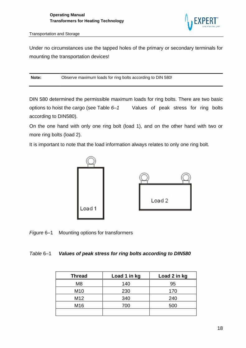
DIN 580 determined the permissible maximum loads for ring bolts. There are two basic
options to hoist the cargo (see Table 6–1 Values of peak stress for ring bolts
according to DIN580).
On the one hand with only one ring bolt (load 1), and on the other hand with two or
more ring bolts (load 2).
It is important to note that the load information always relates to only one ring bolt.
Figure 6–1 Mounting options for transformers
Table 6–1 Values of peak stress for ring bolts according to DIN580
Thread Load 1 in kg Load 2 in kg
M8 140 95
M10 230 170
M12 340 240
M16 700 500

Operating Manual
Transformers for Heating Technology
Transportation and Storage
19
6.2 Storage
If transformers are subjected to strong external magnetic fields, e.g. when stored in
immediate vicinity of induction-heated furnaces, lifting magnets, etc., then these fields
can induce voltages into the transformer non-connected windings. Depending on the
transformer nature and design it cannot be excluded that these induced values can
assume impermissible high values. Therefore storage in the influence area of large
alternating magnetic fields is not allowed.
The following conditions apply for the storage of EXPERT transformers.
Storage conditions:
Permissible storage altitude above sea level: no restriction
Permissible ambient temperature: - 25 to +60 °C, (water circuit drained)
Permissible relative air humidity: 20 – 80 % (no condensation)
Stacking height: max. 2 transformers one flat upon the
other, take care of possibly projecting
screw fittings!
Danger through frost damages!
Storage of non-drained transformers below freezing point can cause the cooling pipe to crack due to residual water’s change of volume. Absolutely drain the entire transformer water circuit completely!

Operating Manual
Transformers for Heating Technology
Installation, Electrical Connection and Commissioning
20
7 Installation, Electrical Connection and Commissioning
Non-observation of the following general notes can lead to exclusion of warranty claims
(“caveat emptor”) by EXPERT Maschinenbau GmbH.
Installation personnel requirements:
Professional electricians only are allowed to carry out connection (installation) as well as subsequent commissioning!
7.1 Mounting and Electrical Installation
Please observe the following notes:
There is danger on handling and mounting transformers due to their high weights.
Danger through improper handling!
There is danger of personal injuries by bruising, shearing, cutting, bumping!
Places of installation and attachments need to be dimensioned for the transformer
weights.
Always use suitable installation and transportation devices.
Use lifting devices and tools professionally. Observe the permissible load.
Take care that the terminals for primary, secondary, and subcircuits remain
accessible.
The type plate shall be easily readable or repeat the technical data where visible.
Carry out the cooling water connection professionally. The cooling-water connections
on the transformer can have potential differences. To avoid a short circuit through the
water connections, use only non-conductive hoses or pipes with a length on 0.5 m
and an electric resistance of 1 MΩ/m minimum. The specific resistance of the water
column should be 20 Ωm minimum (cf. EN50063, section 5.1.3.1)
Check the cooling water connection for tightness and function.

Operating Manual
Transformers for Heating Technology
Installation, Electrical Connection and Commissioning
21
Electrical connections by professional electricians only.
Explanation of the term “professional”:
A professional is who has knowledge and experience owing to professional training as well as knowledge
of the relevant standards for the work entrusted to him/her. A passed vocational training as skilled worker,
master craftsman/craftswoman, technician, or qualified engineer is considered proof of the required
professional training. In addition, a professional (skilled person) needs to know all standards relevant to
his/her sphere of activity and command sufficient experience within a certain scope of work enabling
him/her to assess work entrusted with and to identify dangers. The skilled person, furthermore, is trained,
instructed, or authorized to switch on and off electric circuits and equipment according to the regulations,
to ground them and to mark them. The skilled person has appropriate technical equipment and is trained
in first aid.
The primary and secondary terminal faces need to be plane and have bright
contacts.
Tighten the terminal studs in the primary area with a torque wrench. We recommend
tightening torques according to Table 7–2 Screwed connections for electrical
terminals at different material pairing
(Specification in Nm for screws and nuts strength 8.8)
All live parts need to be covered and hence secured against direct contact.
Keep and check following tightening torques for screwed connections:
Table 7–1 Tightening torques, general, for transformer attachment (transformer
housing) in Nm, screw strength 8.8
Thread M5 M6 M8 M10 M12 M16 M18 M20
Tightening torque / Nm 5.75 9.9 24 48 83 200 275 390

Operating Manual
Transformers for Heating Technology
Installation, Electrical Connection and Commissioning
22
Table 7–2 Screwed connections for electrical terminals at different material pairing
(Specification in Nm for screws and nuts strength 8.8)
Thread Cu flange
Cu busbar
Cu flange
Cu flexible
Contact piece/
Cable lug
M5 5.5 5.5 5.5
M6 9 9 8
M8 23 23 20
M10 45 45 42
M12 85 85 80
M16 160 160 150
M18 220 220 200
M20 250 250 220
There is no standard regulation for maximum permissible tightening torques for screwed
Cu connections right now. The tightening torques stated in Table 7–2 Screwed
connections for electrical terminals at different material pairing
(Specification in Nm for screws and nuts strength 8.8) have been determined by
experiments. Take care not to have screwed Copper connections overstressed.
Overtightening can deform copper due to its yielding behavior.
7.2 Permissible Environmental Conditions
The transformer fulfills, in its standard version, IP54 (= International Protection) for the
primary connection. The system of protection for the secondary terminal is IP00.
Use in potentially explosive rooms is not permissible.
The following environmental conditions are valid for operation:
Permissible guaranteed site altitude: 1000 m above sea level
Permissible ambient temperature: + 5 to + 40 °C
(varying ambient temperatures possible for special types, shown in the data sheet)
Temperature of cooling water: max. 30 °C (flow)

Operating Manual
Transformers for Heating Technology
Notes on Operation of Transformers
23
Permissible relative air humidity: 30 to 95 %
8 Notes on Operation of Transformers
8.1 Cooling Water Quality
Insufficient quality of the cooling water can limit the function of the transformer
considerably. Use of closed-circuit cooling in which processed water can be cooled
back would be advantageous in any case. In order not to increase specific electrical
cooling water conductivity, we advise to install an ion exchanger into the cooling circuit
of larger installations, or to provide for regular exchange of the cooling water. Metal ions
such as iron, copper, etc. are released into the cooling water due to potential
differences in the cooling pipes. The ions increase the cooling water specific electrical
conductivity.
Beyond that, the metal ions of the transformer cooling circuit (copper pipe) contained in
the cooling water can form local corrosion centers according to their position in the
electrochemical series of metals.
Since the secondary circuit is directly flown through by the cooling water, it should have
relatively good insulating properties in order to avoid formation of parasitic voltages (cf.
EN50063, section 5.1.3.1).
Cooling water requirements:
Mechanically clean, filter degree of fineness approx. 100 Micron
Natural water, optically clear, without turbidity, no bottom settling
pH value: 7-8
Spec. electr. conductivity: max. 500 µS
Water hardness: max. 6 °DH
Iron: < 0.3 mg/l
Operating Manual
Transformers for Heating Technology
Notes on Operation of Transformers
24
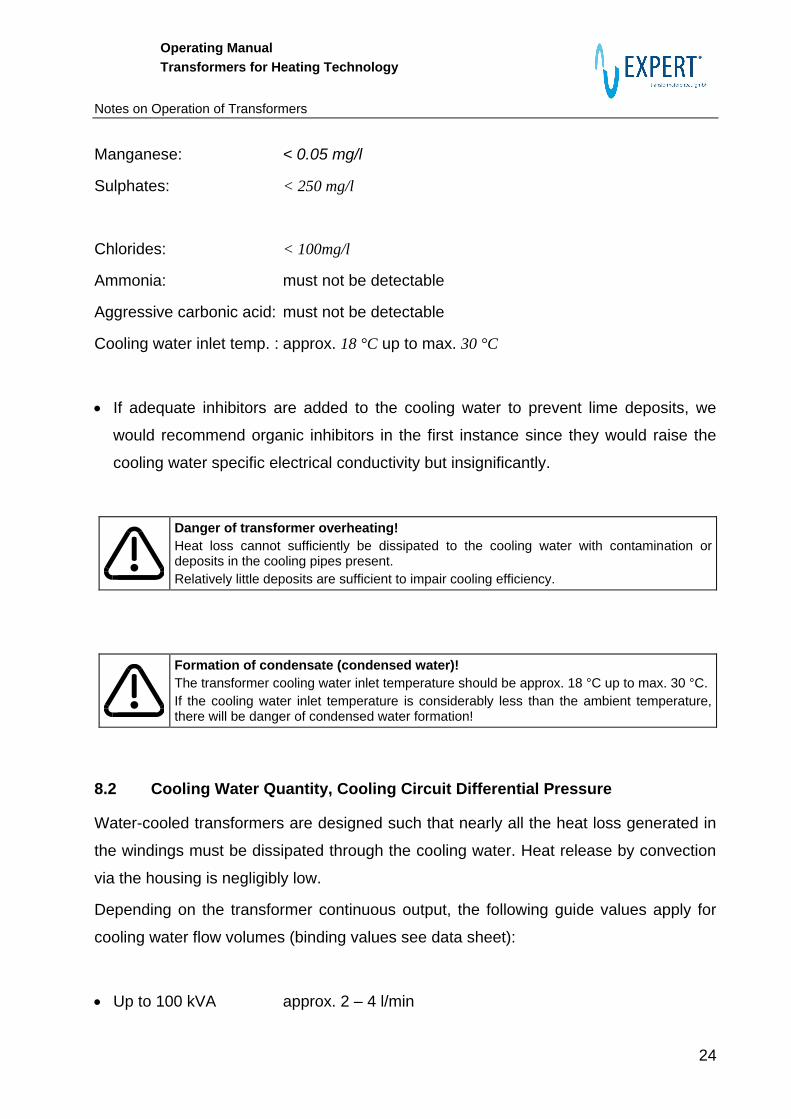
Manganese: < 0.05 mg/l
Sulphates: < 250 mg/l
Chlorides: < 100mg/l
Ammonia: must not be detectable
Aggressive carbonic acid: must not be detectable
Cooling water inlet temp. : approx. 18 °C up to max. 30 °C
If adequate inhibitors are added to the cooling water to prevent lime deposits, we
would recommend organic inhibitors in the first instance since they would raise the
cooling water specific electrical conductivity but insignificantly.
Danger of transformer overheating!
Heat loss cannot sufficiently be dissipated to the cooling water with contamination or deposits in the cooling pipes present.
Relatively little deposits are sufficient to impair cooling efficiency.
Formation of condensate (condensed water)!
The transformer cooling water inlet temperature should be approx. 18 °C up to max. 30 °C.
If the cooling water inlet temperature is considerably less than the ambient temperature, there will be danger of condensed water formation!
8.2 Cooling Water Quantity, Cooling Circuit Differential Pressure
Water-cooled transformers are designed such that nearly all the heat loss generated in
the windings must be dissipated through the cooling water. Heat release by convection
via the housing is negligibly low.
Depending on the transformer continuous output, the following guide values apply for
cooling water flow volumes (binding values see data sheet):
Up to 100 kVA approx. 2 – 4 l/min

Operating Manual
Transformers for Heating Technology
Notes on Operation of Transformers
25
100 kVA approx. 6 – 8 l/min
Pressure drop in the transformer is approx. 0.5 – 1.0 bar (pressure difference
between water inlet and water outlet)
Additional pressure losses develop in the external cooling circuit (hoses, screw fittings,
etc.).
The user needs to determine the differential pressure between the cooling water inlet
and outlet such that the cooling water quantity stated in the data sheet is reached. For
checking the cooling water quantity, we recommend installation of a flowmeter.
Depending on the amount of the transformer no-load losses, the cooling water outlet
temperature is approx. 10 – 30 K higher than the inlet temperature.
Water connection
The transformer cooling water inlet temperature can be 30 °C maximum.
Cooling circuit series connection of several transformers is not allowed.
Pressure in the cooling system may be maximum 8 bar higher than external pressure (atmosphere).

Operating Manual
Transformers for Heating Technology
Inspection and Maintenance
26
9 Inspection and Maintenance
Regular inspection enhances installation dependability.
EXPERT transformers are of low-maintenance type thanks to their compact and fully
encapsulated design.
9.1 Primary and Secondary Terminals
We recommend maintenance cycles of approx. 10 – 12 weeks. Inspect particularly the
condition of the connection points (corrosion and tightness of connections) as well as
heavy-current lines themselves for wear or damages.
Prior to commencing work, observe the notes on safety according to section 2.
Isolate the transformer and protect it against reclosure (see section 2.1).
Primary or secondary lines should be replaced if damaged.
Check primary and secondary tightening torques (see Table 7–2 Screwed
connections for electrical terminals at different material pairing
(Specification in Nm for screws and nuts strength 8.8)).
In case of fault, check efficiency of protective measures against indirect contact with
suitable measuring equipment (e.g. condition and function of protective conductor
connections, function of current-operated ground-leakage protection, or similar).
Commissioning to take place observing sections 2 and 0.
9.2 Cooling circuit
Frequency of maintenance work depends on the quality of the cooling water used (see
also section 8.1).
Deposits in the cooling channels may reduce the transformer temperature difference
rating drastically. Transformer thermal overload is quite often the consequence (e.g.
tripping of temperature monitoring). Beyond that, deposits reduce the hydraulic cross
section in the cooling channels. This increases transformer pressure drop as
consequence.

Operating Manual
Transformers for Heating Technology
Inspection and Maintenance
27
Performing cleaning work on the cooling circuit:
Prior to commencing work, observe the notes in section 2.
Disconnect cooling water supply for the transformer.
Remove the hoses for the transformer cooling water connection.
Rinse transformer cooling circuits with appropriate solvents for degrading lime and
scale residue. Observe solvent manufacturer’ s information on safety and directions
for use. Strong deposits may require repetition of the rinsing procedures several
times or extend exposure time.
Commercially available agents such as NALCO 68, SILIT, etc. are suitable for
removing deposits from the cooling circuits.

Operating Manual
Transformers for Heating Technology
Standards and Regulations
28
10 Standards and Regulations
DIN EN 294 Safety of machinery. Safety distances to prevent danger zones from
being reached by the upper limbs
DIN EN 418 Safety of machinery, emergency stop equipment, functional
aspects, principles for design
DIN EN 50063 Safety requirements for the construction and the installation of
equipment for resistance welding and allied processes.
DIN EN 50081-2 Electromagnetic compatibility (EMC), basic specification Emitted
Interference
DIN EN 60204-1 Safety of machinery – Electrical equipment of machines, general
requirements
E DIN ISO 5826 Resistance welding equipment - Transformers - General
specifications applicable to all transformers
ISO/DIN 5828 Resistance welding equipment - Secondary connecting cables with
terminals connected to water-cooled lugs - Dimensions and
characteristics
DIN EN ISO 8205-1 Water-cooled secondary connection cables for resistance welding -
Part 1: Dimensions and requirements for double-conductor
connection cables
DIN EN ISO 8205-2 Water-cooled secondary connection cables for resistance welding -
Part 2: Dimensions and requirements for double-conductor
connection cables
DIN VDE 0545-1 Safety requirements for the construction and the installation of
equipment for resistance welding and allied processes.
Operating Manual
Transformers for Heating Technology
Standards and Regulations
29
Notes :