transformer short circuit current calculation and solutions · 2018-10-02 · 1.2 needs of...
TRANSCRIPT

Transformer Short Circuit Current
Calculation and Solutions
Ling Song
Bachelor’s Thesis
Electrical Engineering
Vaasa 2013

BACHELOR’S THESIS
Author: Ling Song
Degree Programme: Electrical Engineering
Specialization: Electrical Power
Supervisor: Lars Enström
Title:
Transformer Short Circuit Current Calculation and Solutions
Date Number of pages Appendices
14 June 2013 31 pages 0 page
Summary
There are three goals for the thesis. The first one is to introduce types of short-circuits. The
second one is to introduce the transformer short-circuit current calculations. And the last
one is to find suitable reinforcement methods for the transformers which are running now.
Using a comparative approach to analytic research, the advantages and disadvantages of
different reinforcement methods can be analyzed. The result shows that the neutral reactor
is the best choice to reinforce the S/C withstand capability: low cost, easy maintenance,
high technique maturity and so on.
Language: English
Key words: short-circuit, transformer calculation methods, short-circuit withstand
capability

Table of the contents
1 Background ......................................................................................................................... 1
1.1 Introduction to the short circuit phenomenon ........................................................ 1
1.2 Needs of transformer short-circuit current calculation............................................ 2
1.3 Symmetrical components ......................................................................................... 4
2 Different kinds of short circuits .......................................................................................... 6
2.1 DC circuits ................................................................................................................. 6
2.2 AC circuits.................................................................................................................. 7
2.2.1 Single-phase circuits ....................................................................................... 7
2.2.2 Three-phase circuits........................................................................................ 8
2.2.3 Development of short-circuit current........................................................... 10
3 Calculation methods for transformers .............................................................................. 13
3.1 Single transformer model ....................................................................................... 13
3.2 Practical calculation methods ................................................................................. 15
3.2.1 The calculation by the impedance method ................................................... 15
3.2.2 The calculation in grid network using symmetrical components ................. 17
4 Reinforcement of S/C withstand capability ...................................................................... 19
4.1 Installation of neutral reactors ............................................................................... 19
4.2 Installation of current limitation series reactors .................................................... 21
4.3 Installation of fast switches with high capacity ...................................................... 22
4.4 Installation of controllable Fault Current Limiters .................................................. 25
4.5 The comparison ...................................................................................................... 26
4.6 Practical work applications ..................................................................................... 27
5 The conclusion .................................................................................................................. 28
6 References......................................................................................................................... 29

List of figures
Figure 1. Sequence components to represent the three-phase electrical system ................... 4
Figure 2. The current in an inductor .................................................................................... 6
Figure 3. The fault types..................................................................................................... 9
Figure 4. The simple S/C circuit..............................................................错误!未定义书签。
Figure 5. The currents continue symmetrically....................................................................11
Figure 6. The currents continue asymmetrically ..................................................................12
Figure 7. The Dyn11 transformer circuit .............................................................................13
Figure 8. Various S/C currents in calculation done according to the impedance method........16
Figure 9. Neutral earthing reactor made by Hilkar®.............................................................19
Figure 10. The neutral reactor on three-winding transformer (in red cycle) ..........................20
Figure 11. Neutral earthing reactor made by ABB ...............................................................20
Figure 12. Core-and-coil assembly of a series reactor (made by Siemens).............................22
Figure 13. The Is-limiter process ........................................................................................24
Figure 14. Superconducting FCL (35 kV/90 MVA) made in China ..........................................25
Figure 15. Series controllable FCL schematic.......................................................................26
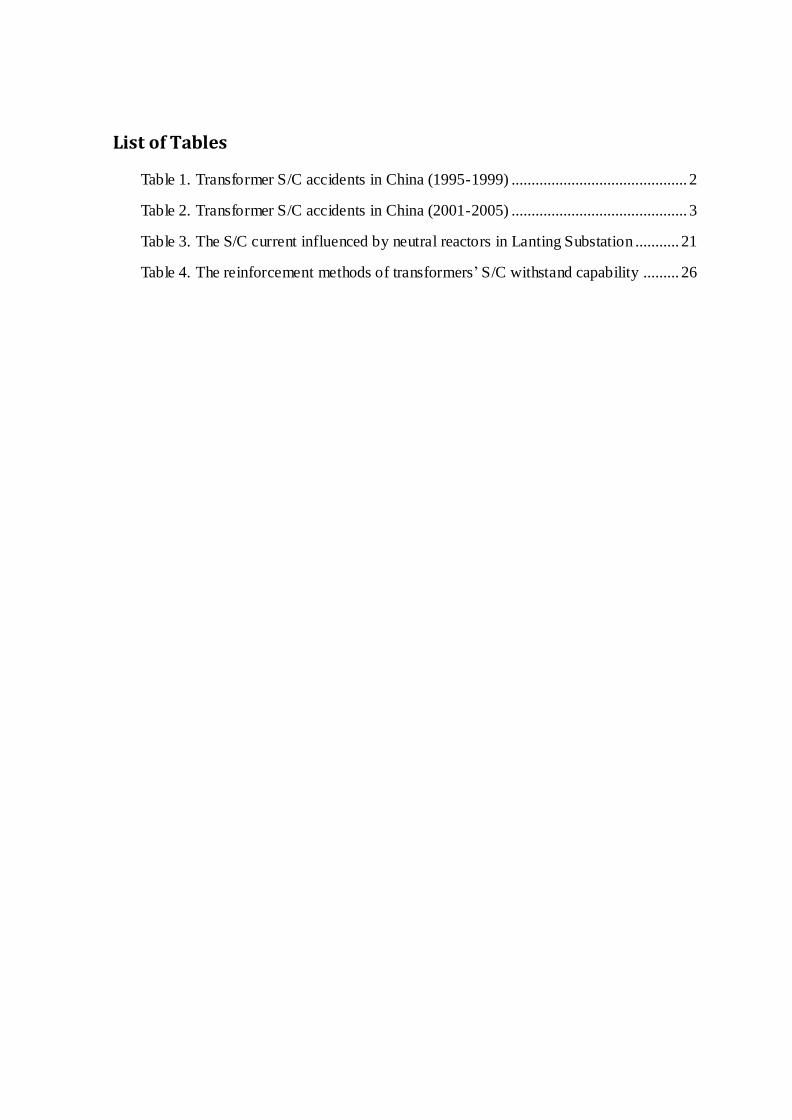
List of Tables
Table 1. Transformer S/C accidents in China (1995-1999) ............................................ 2
Table 2. Transformer S/C accidents in China (2001-2005) ............................................ 3
Table 3. The S/C current influenced by neutral reactors in Lanting Substation ........... 21
Table 4. The reinforcement methods of transformers’ S/C withstand capability ......... 26

ABBREVIATIONS
S/C short circuit
AC alternating current
DC direct current
Emf electromotive force
HV high voltage
LV low voltage
MV medium voltage
SGCC State Grid Corporation of China
1
1 Background
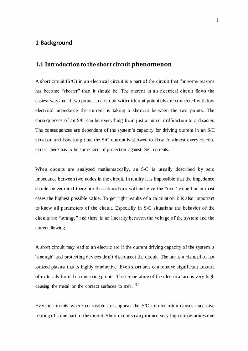
1.1 Introduction to the short circuit phenomenon
A short circuit (S/C) in an electrical circuit is a part of the circuit that for some reasons
has become “shorter” than it should be. The current in an electrical circuit flows the
easiest way and if two points in a circuit with different potentials are connected with low
electrical impedance the current is taking a shortcut between the two points. The
consequences of an S/C can be everything from just a minor malfunction to a disaster.
The consequences are dependent of the system s capacity for driving current in an S/C
situation and how long time the S/C current is allowed to flow. In almost every electric
circuit there has to be some kind of protection against S/C currents.
When circuits are analyzed mathematically, an S/C is usually described by zero
impedance between two nodes in the circuit. In reality it is impossible that the impedance
should be zero and therefore the calculations will not give the “real” value but in most
cases the highest possible value. To get right results of a calculation it is also important
to know all parameters of the circuit. Especially in S/C situations the behavior of the
circuits are “strange” and there is no linearity between the voltage of the system and the
current flowing.
A short circuit may lead to an electric arc if the current driving capacity of the system is
“enough” and protecting devices don t disconnect the circuit. The arc is a channel of hot
ionized plasma that is highly conductive. Even short arcs can remove significant amount
of materials from the contacting points. The temperature of the electrical arc is very high
causing the metal on the contact surfaces to melt. /1/
Even in circuits where no visible arcs appear the S/C current often causes excessive
heating of some part of the circuit. Short circuits can produce very high temperatures due

2
to the high power dissipation in the circuit.
A practical example of heating due to a short circuit is arc welding. The power supply for
an arc welder can supply very high currents that flow through the welding rod and the
metal pieces being welded. The point of contact between the rod and the metal surfaces
gets heated to the melting point, fusing a part of the rod and both surfaces into a single
piece. /2/
1.2 Needs of transformer short-circuit current calculation
Today more than ever before, the electricity grid is developing so quick ly — the power
plant capacity, the substation capacity and electricity loads, as well as load density,
sustainably grow. Take China as an example. The number of 500 kV substations in the
North China power grid is almost 2 times higher than in the past decade. The number has
grown from 48 to 97; the substation capacity has increased from 52,069,000 kVA to
157,960,000 kVA. /3/
As a result, the short-circuit currents in the power grid increase year by year. Based on
the statistical analysis of the State Grid Corporation of China (SGCC) /4/, /5/, the S/C
current accidents of power transformers (Size ≥ 110 kV) happened 125 times. The total
power capacity influenced by the S/C accidents is 7,996 MVA in 1995~1999. The
number represents 37.5% of all power accidents and 44% of the transformers accidents.
The details are shown in Table 1 and Table 2.
Table 1. Transformer S/C accidents in China (1995-1999)
year 1995 1996 1997 1998 1999 Total
Accident times 59 58 55 63 49 284
S/C accident times 29 29 21 26 20 125
The rate 49.2% 50% 38.2% 41.3% 40.8% 44%
3
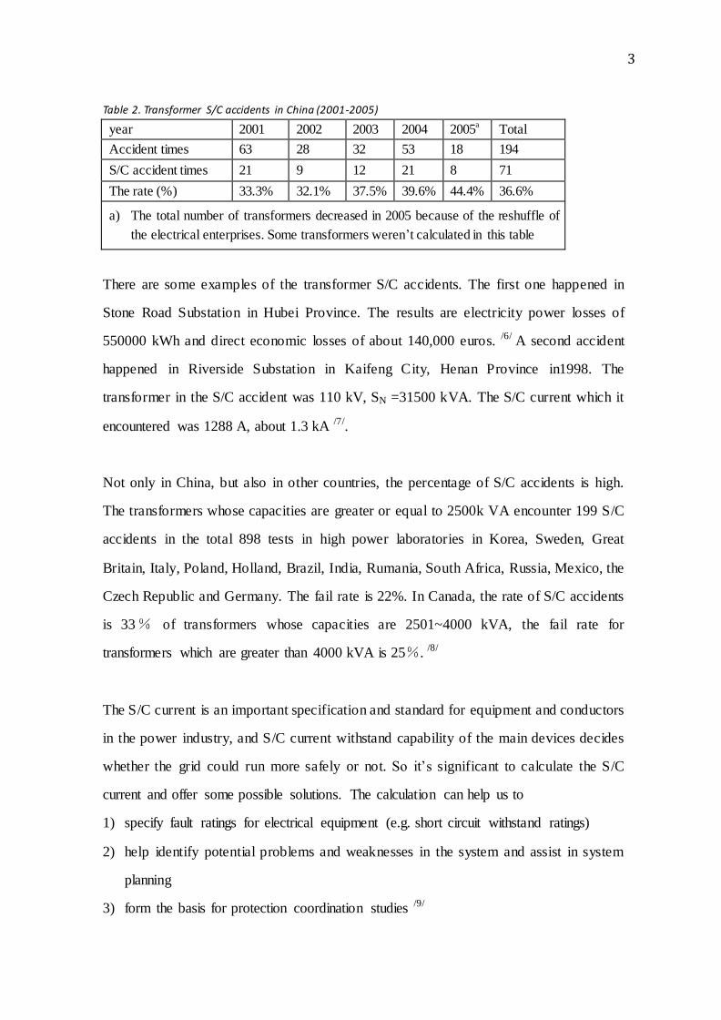
Table 2. Transformer S/C accidents in China (2001-2005)
year 2001 2002 2003 2004 2005a Total
Accident times 63 28 32 53 18 194
S/C accident times 21 9 12 21 8 71
The rate (%) 33.3% 32.1% 37.5% 39.6% 44.4% 36.6%
a) The total number of transformers decreased in 2005 because of the reshuffle of
the electrical enterprises. Some transformers weren’t calculated in this table
There are some examples of the transformer S/C accidents. The first one happened in
Stone Road Substation in Hubei Province. The results are electricity power losses of
550000 kWh and direct economic losses of about 140,000 euros. /6/ A second accident
happened in Riverside Substation in Kaifeng City, Henan Province in1998. The
transformer in the S/C accident was 110 kV, SN =31500 kVA. The S/C current which it
encountered was 1288 A, about 1.3 kA /7/.
Not only in China, but also in other countries, the percentage of S/C accidents is high.
The transformers whose capacities are greater or equal to 2500k VA encounter 199 S/C
accidents in the total 898 tests in high power laboratories in Korea, Sweden, Great
Britain, Italy, Poland, Holland, Brazil, India, Rumania, South Africa, Russia, Mexico, the
Czech Republic and Germany. The fail rate is 22%. In Canada, the rate of S/C accidents
is 33% of transformers whose capacities are 2501~4000 kVA, the fail rate for
transformers which are greater than 4000 kVA is 25%. /8/
The S/C current is an important specification and standard for equipment and conductors
in the power industry, and S/C current withstand capability of the main devices decides
whether the grid could run more safely or not. So it’s significant to calculate the S/C
current and offer some possible solutions. The calculation can help us to
1) specify fault ratings for electrical equipment (e.g. short circuit withstand ratings)
2) help identify potential problems and weaknesses in the system and assist in system
planning
3) form the basis for protection coordination studies /9/
4
So, it is not only the S/C calculation methods that are necessary but also the power
transmission and the transformation devices should be equipped with better withstand
ability for the higher S/C currents.
1.3 Symmetrical components
In the practical work, engineers often use “symmetrical components” to analyze the
three-phase power system.
It was invented by a Canadian electrical engineer Charles L.Fortescue in 1913. Mr
Fortescue’s original purpose was to analyze the operation of the electrical motors. The
theory was not used for the power system until 1937. The analytical technique was
adopted and advanced by engineers at General Electric and Westinghouse and after
World War II it was an accepted method for asymmetric fault analysis. Now it’s a
common tool used to analyze the faults of three-phase power system. /10/
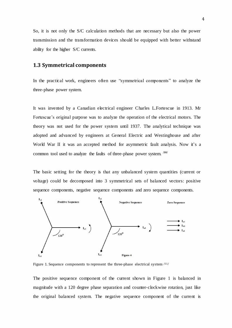
The basic setting for the theory is that any unbalanced system quantities (current or
voltage) could be decomposed into 3 symmetrical sets of balanced vectors: positive
sequence components, negative sequence components and zero sequence components.
Figure 1. Sequence components to represent the three-phase electrical system /11/
The positive sequence component of the current shown in Figure 1 is balanced in
magnitude with a 120 degree phase separation and counter-clockwise rotation, just like
the original balanced system. The negative sequence component of the current is

5
balanced in magnitude with a 120 degree phase separation, but has the opposite rotation,
in this case, clockwise. The zero sequence components have equal magnitudes, but zero
phase separation. Here, we denote the positive sequence with the subscript “1”. Likewise,
the negative sequence is denoted with the subscript “2” and the zero sequence is denoted
with the subscript “0”.
Under a no fault condition, the power system is considered to be essentially a
symmetrical system and therefore only positive sequence currents and voltages exist. At
the time of a fault, positive, negative and possibly zero sequence currents and voltages
exist. Using real world phase voltages and currents along with Fortescue’s formulas, all
positive, negative and zero sequence currents can be calculated. Protective relays use
these sequence components along with phase current and/or voltage data as the input to
protective elements. /12/

6
2 Different kinds of short circuits
2.1 DC circuits
What circuit information is needed to do an S/C calculation for a DC circuit? In an
electrical circuit the current is dependent of the electromotive force (emf), the
electromagnetic field, and the total impedance of the circuit. In a battery the emf-value is
dependent of the charge of the battery. The internal impedance of the battery is also a
changing parameter and dependent of the charge, the temperature, and the age of the
battery and so on. In a DC circuit the resistance is the current limiting factor together
with the emf in steady-state which means “after a while”. In the beginning of a transient,
like an S/C situation, also the inductance of the circuit is limiting. Any inductance in the
circuit will smooth up the rise of the current. The current is increasing exponentially due
to the relation between the inductance and the resistance of the circuit.
Figure 2. The current in an inductor /13/
Direct current causes different problems from AC when trying to interrupt high value
currents since the arc extinction is more difficult. AC passes through zero every half period
thus helping the breaking of current. A circuit breaker for a certain AC current is usually
not able to break the same magnitude of DC current. The difficulties of breaking a DC

7
circuit increases with the ratio of inductance versus resistance in the circuit. Inductances
are always in opposition to changes of current.
2.2 AC circuits
Alternating current circuits (AC) are more complex to solve than direct current circuits
(DC). There are more parameters affecting the results and in fast changing situations the
first values of current are strongly dependent of the phase of the active voltage source.
2.2.1 Single-phase circuits
Most large power networks are three-phase but especially in low voltage systems most of
the connected circuits are single-phase. When calculating S/C currents the situation is
dependent on how near the generator or transformer the fault occurs. Not only due to the
increasing impedance in the end of the network but also to the fact that generators and
transformers are acting “strange” when they are not loaded symmetrically in all phases. In
some cases the circuit may be fed from a single-phase transformer with a current carrying
capacity that is not enough to make the three-phase system behave “strange”. The fact that
the S/C current is easier to calculate far from a transformer or a generator is because the
line impedances are playing an important role in the process and the impedances are often
easier to know than the voltage in the beginning of the c ircuit. With longer lines the
currents decreases and the voltage from the source will not change very much.
In single-phase low voltage circuits that are commonly used in households the S/C currents
must be disconnected for different reasons. One reason is because of the touch voltage that
may occur during a contact between phase and protective earth. The protective earth in a
circuit is used to prevent exposed conductive parts from getting a dangerous potential
referred to earth. When a direct contact between phase and exposed conductive parts is
established by a fault situation the potential will rise to a dangerous level for persons to
touch and therefore the circuit must be disconnected by protection devices like fuses and
circuit breakers. In household situations the maximum time for disconnection is normally
0.4 seconds.

8
To access the clearance time under fault conditions the prospective fault current must be
determined by measurement or calculation. It is the prospective current that will flow when
the end of the cable being protected is connected to the protective earth conductor that is of
concern. With long cable runs this prospective current can be found to be comparatively
low. It should be remembered however that the first problem with long cable runs is the
possibility of excessive voltage drop, and cables should be selected first for current rating,
and then checked for voltage drop before determining the fault prospective. /14/
2.2.2 Three-phase circuits
Three-phase electric power is a common method of AC electric power generation,
transmission, and distribution. It is a type of poly-phase system and is the most common
method used by electrical grids worldwide to transfer power. It is also used to power
large motors and heavy loads. A three-phase system is usually more economical than an
equivalent single-phase or two-phase system at the same voltage because it uses less
conductor material to transmit electrical power. The three-phase system was
independently invented by Galileo Ferraris, Mikhail Dolivo-Dobrovolsky and Nikola
Tesla in the late 1880s. /15/
Most single-phase circuits are just a part of a three-phase network. In a three-phase
system various types of S/C can occur. For example, S/C current can be phase-to-earth
(80% of faults), phase-to-phase (15% of faults — this type of fault often degenerates into
a three-phase fault) and three-phase (only 5% of initial faults). These different
short-circuit currents are shown in Figure 3. In China, there is another rough
classification which is based on the number of the fault phase: three-phase fault,
double-phase fault and single phase fault due to phase-to-earth fault which may happen
for two phases.
The primary characteristics of short-circuit currents are:
1) Duration: The current can be self-extinguishing, transient or steady-state
2) Origin: it may be caused by mechanical reasons (break in a conductor, accidental

9
electrical contact between two conductors via a foreign conducting body such as a
tool or an animal), internal or atmospheric overvoltage, and insulation breakdown
due to heat, humidity or a corrosive environment
3) Location (inside or outside a machine or an electrical switchboard)
Figure 3. The fault types /16/
The consequences of S/C are depending on the type and duration of the fault and the
short-circuit power available. Locally at the fault point there may occur electrical arcs
causing damage to insulation, welding of conductors and fire. On the faulty circuit,
electro dynamic forces may result in deformation of bus bars and cables and the
excessive temperature rise may damage insulation. Other circuits in the network or in
nearby networks are also affected by the short-circuit situation. Voltage drops occur in
other networks during the time of S/C and shutdown of a part of a network may include
also “healthy” parts of the network depending on the design of the whole network.

10
2.2.3 Development of short-circuit current
A simplified AC network can be represented by a source of AC power, some kind of
switching device, a total impedance ZN that represents all the impedances upstream of the
switching point and a load, represented by its impedance (see figure 4). In a real network
the total impedance ZN is made up of the impedances of all components upstream. The
components are for example generators, transformers, wires, circuit-breakers and metering
systems.
When a fault with negligible impedance occurs between A and B a short-circuit current
limited only by ZN flows in the circuit. The short-circuit current Isc develops under
transient conditions depending on the relation between inductances and resistances in the
whole circuit. If the circuit is mostly resistive the waveform of the current is following the
waveform of the voltage but if there are inductances in the circuit the waveform of the
current will differ from the waveform of the voltage during a transient time of the process.
In an inductive circuit the current cannot begin with any value but zero. The influence of
inductances is described by reactance X in AC circuits with a fixed frequency of the
voltage. In low voltage systems where cables and conductors represent most of the
impedance it can be regarded as mostly resistive. In power distribution networks the
reactance is normally much greater than the resistances. Generally the total impedance Z in
steady-state in an AC circuit is made up of the total resistance R and the total reactance X
as the following relation shows.
2 2Z R X

11
Figure 4. The simple S/C circuit
In the simplified circuit above the voltage is constant and so is the total impedance. In
faults far from generators and transformers where most of the impedance consists of
impedances from wires the calculations can be done with a good result and the transient
current is almost the same as if the current would flow for a longer time. The meaning of
far from is not necessarily physical but means that generator or transformer impedances
are less than the impedance of the elements from wires. The impedance elements from
wires are constant at a constant temperature but the impedances of generators vary during
a short-circuit and the impedances of transformers change if the transformers are
asymmetrically loaded with high currents.
Figure 5. The currents continue symmetrically
Figure 5 shows the current in beginning of a short-circuit far from the generator. The
short-circuit starts at a moment when the current normally is zero and continues
symmetrically.

12
Figure 6. The currents continue asymmetrically
Figure 6 shows the current when the short-circuit starts at a moment when the voltage is
zero and the current is also starting from zero but asymmetrically during a transient time.

13
3 Calculation methods for transformers
In Chapter 1, the data show the importance of transformer S/C current calculations and
introduce the symmetrical components theory briefly. Let’s discuss the calculation
methods on the basis of two single transformer models in Chapter 3.
3.1 Single transformer model
In this section, I will begin with two examples:
Figure 7. The Dyn11 transformer circuit
Example 1: one transformer which has SN=100 kVA, Dyn11 connection. The
transformation rate is 20500 V/ 410 V. P0=220 W, Pk=1485W, Zk=3.8%, Z0=3.8%.
The calculation of its S/C current is as follows:
The rated currents:
I1N=SN/(√3*U1N) = 100000/ (1.732*20500) = 2.82 A
I2N=SN/(√3*U2N) = 100000/ (1.732*410) = 140.82 A
The impedance:
= 0.038* 4102/100000=63.88 mΩ
= 1485/ (3* 140.822)=24.97 mΩ
Since we have ,

14
=√ = 58.8 mΩ
If U1=U1N=20500V, the three-phase S/C at the terminals will be:
= U2N/ (√ *
) = 410/ (1.732*0.0639) = 3705.6A≈3700 A
In the single phase fault accidents, the current will not change if it’s the phase-neutral
case. But the performance of the transformer will be abnormal. In special cases, the
current may be greater (Yzn). If the transformer is Dyn connected, the single phase
current will be less than the three-phase current.
Example 2: a power transformer which has SN = 63 MVA. The transformation rate is 110
kV/ 21 kV. P0=32.0 kW, Pk=210 kW, Zk=12%. Calculate the short-circuit current.
The calculation of its S/C current is as follows:
I1N=SN/(√3*U1N) = 63*106/ (1.732*110k) = 330.7 A
I2N=SN/(√3*U2N) = 63*106/ (1.732*21k) = 1732 A
The impedance:
= 0.12* (21*103)2/(63*106)=23.05 Ω
=0.12* (110*103)2/(63*106)=0.840 Ω
Short circuit current with nominal voltage (three-phase symmetrical)
= U1N/ (√ *
) = 110*103/ (1.732*23.05) = 2755 A
= U2N/ (√ *
) = 21*103/ (1.732*0.840) = 14.43k A
There is always a voltage drop in the upstream network. That means that the voltage will
be lower than the nominal voltage when the S/C accident happens.

15
3.2 Practical calculation methods
The practical calculation methods are more complex than the simple model. There are
two types: calculating S/C current by the impedance method and the calculation in grid
network using symmetrical components.
3.2.1 The calculation by the impedance method
The impedance method, reserved primarily for LV networks, was selected for its high
degree of accuracy and its instructive value, given that virtually all characteristics of the
circuit are taken into account. Figure 5 shows the various S/C currents.
The three-phase S/C involves all three-phases. Short-circuit current Isc3 is equal to:
Isc3 =U / √3/ Zsc,
where U (phase-to-phase voltage) corresponds to the transformer no- load voltage which is
3 to 5% greater than the on- load voltage across the terminals. In fact, this is the
“positive-sequence” impedance per phase in the symmetrical components theory. It is
generally considered that three-phase faults offer the highest fault currents.
Phase-to-phase S/C without earthing is the fault between two phases which is supplied
with a phase-to-phase voltage U. The formula is:
Isc2 =U / 2 Zsc.

16
Figure 8. Various S/C currents in a calculation done according to the impedance method
The third fault type is Phase-to-neutral S/C without earthing. This is a fault between one
phase and the neutral, supplied with a phase-to-neutral voltage:
3f
UU
The calculation formula is:
Isc1 =sc LnZ Z
fU
.
The final fault is Phase-to-earth fault (one or two phases). This type of fault brings the
zero-sequence impedance Z0 into play. Except when rotating machines are involved
(reduced zero-sequence impedance), the S/C current Isc0 is less than that of a three-phase
fault. Calculation of Isc0 may be necessary, depending on the neutral system (system
earthing arrangement), in view of defining the setting thresholds for the zero-sequence
(HV) or earth fault (LV) protection devices.

17
3.2.2 The calculation in grid network using symmetrical components
A calculation using symmetrical components is particularly useful when a three-phase
network is unbalanced. This is based on IEC 60909 -0 (2001, c2002), "S/C currents in
three-phase AC systems - Part 0: Calculation of currents" and uses the impedance method
(as opposed to the per-unit method). /17/
Generally speaking, there are six general steps in the calculation: Step 1: Construct the
system model and collect the relevant equipment parameters. Step 2: Calculate the short
circuit impedances for all of the relevant equipment. Step 3: Refer all impedances to the
reference voltage. Step 4: Determine the Thévenin equivalent circuit at the fault location.
Step 5: Calculate balanced three-phase short circuit currents. Step 6: Calculate
single-phase to earth short circuit currents.
The relevant equipment parameters to be collected are as follows:
1) Network feeders: fault capacity of the network (VA), X/R ratio of the network;
2) Synchronous generators and motors: per-unit sub-transient reactance, rated generator
capacity (VA), rated power factor (cosΦ);
3) Transformers: transformer impedance voltage (%), rated transformer capacity (VA),
rated current (A), total copper loss (W);
4) Cables: length of cable (m), resistance and reactance of cable (Ω/km);
5) Asynchronous motors: full load current (A), locked rotor current (A), rated power (W),
full load power factor, starting power factor.
6) Fault limiting reactors: reactor impedance voltage (%), rated current (A).
When we apply this way of calculating into the practical work to obtain accurate results,
we must also consider the following factors: S/C currents of the substation bus, S/C
currents of the short line fault (SLF: A short- line-fault is a fault that occurs on a line a

18
few hundred meters to several kilometers down the line from the circuit breaker
terminal/18/), the marked data of the transformer and output of the power unit, even the
temperature and the running style of the system(maximum load/ minimum load) and so
on.

19
4 Reinforcement of S/C withstand capability
There are many methods applied to reinforce the S/C withstand capability of the
transformers: improvement of the materials, reforming of the design and good
maintenance in the operation process and so on. However, what I want to mentioned here
is methods for the transformers which are in use and those which are hard to modify or
expensive to modify.
4.1 Installation of neutral reactors
Usually, the probability of power systems encountering single phase S/C accidents is
much higher than the probability of power systems encountering three-phase S/C
accidents. The reinforcement of the S/C withstand capability for the transformers can, to
a great degree, reduce the ruin of an S/C accident.
The single phase S/C current is affected by the positive sequence impedance and zero
sequence impedance. One effective way to change the zero sequence impedance is
changing the earthing methods of transformer neutral points, or installing the neutral
grounding reactor. /19/
Figure 9. Neutral earthing reactor made by Hilkar®
Neutral grounding reactors are used for low-impedance grounding of the neutral point of
three-phase networks in order to limit the fault current in the event of a phase-to-ground
S/C (fault current will be limited to the level of the phase-to-phase S/C current). One
reactor terminal is connected to the neutral of the network and the other terminal is

20
grounded. During normal operation of the power system the current flow through the
reactor is almost zero, since it is only driven by the imbalance of the thre e-phase
network.
Figure 10. The neutral reactor on three-winding transformer (in red cycle) /20/
The ordinary installation place of the neutral reactor is in the compensation equipment
called HV shunt reactor. In China, people often use the star connection for the HV shunt
reactor, and then add a reactor in series at the neutral point of the star connection. That’s
so called “high-voltage reactor grounding through small reactance at the neutral point”.
The functions of reactors here are to compensate the phase to phase capacitor and
grounding capacitor, speed up the termination of the secondary arc current and to make it
easier to adopt the single-phase reclosers. /21/
Figure 11. Neutral earthing reactor made by ABB /22/
One application example happened in 2004, in Ningbo City, Zhejiang Province,China.
Engineers installed little reactors which are 15 Ω as the neutral earthing reactor for a
500kV transformer in Lanting Substation. The S/C current decreased. The details are
shown in Table 3

21
Table 3. The S/C current influenced by neutral reactors in Lanting Substation
Single phase S/C current 3 phase S/C current
without reactor (kA) 48.35 55.71
with reactor(kA) 43.34 41.84
When the neutral points connect with reactors, the zero sequence impedance will change.
The grounding S/C current of double phases may be larger than that of the single phase.
So it’s necessary to check both the single phase S/C and double phases S/C after the
installation of a neutral reactor.
4.2 Installation of current limitation series reactors
The series reactor is a high-voltage electrical apparatus designed to limit the current of a
short circuit and maintain adequate voltage on the buses of distribution switchgear during
a short circuit in a network. It consists of an inductance coil. Such reactors are also used
to compensate reactive power in order to improve the transmission capacity of power
lines. /23/
The use of reactors is a traditional and commonly used method for the limitation of the
S/C current. The reactors are usually installed at the areas where the short- line-fault may
happen and connect in series in the circuits which require a limit to the S/C current. The
principle is decreasing S/C currents by increasing the impedance of the circuits. The
advantage is that it’s easier to install and run in safe and reliable ways. The disadvantage
is that the reactor will increase the losses of power. It may influence the stability of the
power system. /24/

22
Figure 12. Core-and-coil assembly of a series reactor (made by Siemens)
The current limitation series reactor is usually applied at outlets of the LV side, and can
also be applied at the 35 kV medium side in 220 kV transformer. This method is suitable
for both three phase S/C and single phase S/C.
The example is ABB. They build a series reactor for the Metro Grid project which
transfers the power from Sydney South to Haymarket Substation in Australia. It’s the
biggest reactor made by ABB.25
4.3 Installation of fast switches with high capacity
The representatives of fast switches with high capacity are Is-limiter (made by ABB),
Pyristor (made by Ferraz) and C-Lip (made by G&W) /26/. This kind of switches can
protect electric devices from larger S/C current shocks and prevent large-area electricity
black-outs caused by the destruction of main equipment due to overcurrent. It has several
advantages in the technical field:
1) Fast cut off ability (less than 2ms);
2) Fast limitation of the large S/C current: Is- limiter is capable of detecting and limiting
an S/C current at the first rise, i.e. in less than 1ms /27/.

23
3) Less occupied space
4) Easy to install and maintain
It is a fault current limiting device that uses chemical charges and current- limiting fuses
to interrupt the fault current within the first quarter to half cycle (i.e. before the first
peak). In a typical Is-limiter design, the device is composed of two current paths
connected together in parallel – one path is an element rated for the full load current
(which can have high continuous current ratings, e.g. 3000 A), and the other path
provides the current limiting function via a current- limiting fuse (which typically has a
continuous current rating of <300 A at 15 kV). /28/
The work principle can be described as follows: when the S/C happens, the current
transformer module detects the signal and transfers it to the control module. Then the
control module is triggered and turns the disconnector on to ‘move’ the S/C current into
the fuse module at the instant. Here, the current is cut off. The interesting thing and
special feature is that the device uses the explosive to get the rapid cut-off ability. It can
limit both S/C currents of single phase and three-phase. /29/
Figure 11. ABB Is-limiter insert holder with insert for 12 kV, 2000 A
The working process can be described as follows:

24
Figure 13. The Is-limiter process

25
4.4 Installation of controllable Fault Current Limiters
Fault Current Limiter (FCL) is also called S/C Current Limiter (SCCL). There are several
different types: Superconducting Fault Current Limiter (SFCL), the one we mentioned in
section 4.3, and the controllable Fault Current Limiter which is based on electronic
technology and so on. /30/
Figure 14. Superconducting FCL (35 kV/90 MVA) made in China
The shortcomings of a superconducting fault current limiter are
1) The working environment is quite harsh: the high-temperature superconductor needs
liquid nitrogen (N2). The critical temperature is 77 K (about -196 ℃). And the
low-temperature superconductor needs liquid nitrogen liquid helium (He). The
critical temperature is 4 K (about 269.15 ℃). Once the working temperature is over
the critical temperature, the SFCL will not able to keep the superconductor character.
2) The technique is not mature enough. In China, there are only two prototypes running.
The number of SFCLs which are running in Switzerland, Germany, Great Britain and
USA is less than 20.
So it’s not suitable to be applied for modifying the transformers that are running now.
However, the controllable Fault Current Limiter based on electronic technology is more
mature than SFCL. There are two types: series and parallel. The operation principle is:
use the electronic apparatuses to break or connect the circuit with high speed. Then the
capacitor, the resistance, or the inductance in series or in parallel at bypass works
immediately to increase impedance of the circuit in order to limit the S/C current. /31/
26
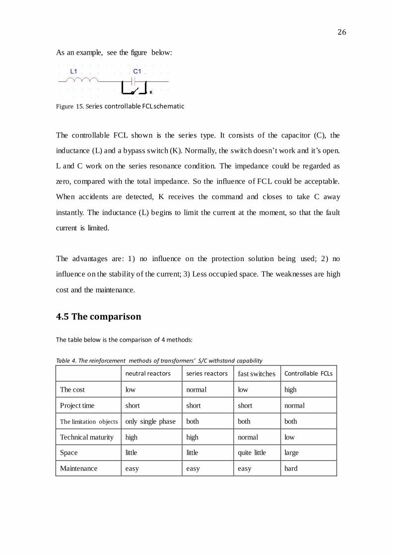
As an example, see the figure below:
Figure 15. Series controllable FCL schematic
The controllable FCL shown is the series type. It consists of the capacitor (C), the
inductance (L) and a bypass switch (K). Normally, the switch doesn’t work and it’s open.
L and C work on the series resonance condition. The impedance could be regarded as
zero, compared with the total impedance. So the influence of FCL could be acceptable.
When accidents are detected, K receives the command and closes to take C away
instantly. The inductance (L) begins to limit the current at the moment, so that the fault
current is limited.
The advantages are: 1) no influence on the protection solution being used; 2) no
influence on the stability of the current; 3) Less occupied space. The weaknesses are high
cost and the maintenance.
4.5 The comparison
The table below is the comparison of 4 methods:
Table 4. The reinforcement methods of transformers’ S/C withstand capability
neutral reactors series reactors fast switches Controllable FCLs
The cost low normal low high
Project time short short short normal
The limitation objects only single phase both both both
Technical maturity high high normal low
Space little little quite little large
Maintenance easy easy easy hard

27
4.6 Practical work applications
Based on the above materials, the technical handbooks (GB1094.5-2003, GB1984-2003
and GB15166.6—2008) and the experience of electrical engineers of SGCC, some
practical work applications are offered. In the practical work, the risk of three-phase S/C
accidents at the MV side of 500 kV and 220 kV transformers is quite little; the main risk
is the single phase accident. The reinforcement of S/C withstand capability of the single
phase or the limitation of the S/C current at the single phase can reduce the number of
transformer S/C accidents significantly. In Table 4, we can find that the new devices
work more effectively and respond much faster, but they are defeated by the traditional
ways in the economy, the reliability, the maturity and the maintenance experience. So the
best selection is to install the neutral reactor. If there does exist the need for three-phase
protection, we can install the fast switch or FCL.
For the LV side accident, people can opt to install current limitation series reactors, or fast
switches if the space is limited.

28
5 The conclusion
The thesis introduces the definition and the importance of S/C current calculations.
Chapter 2 introduces the type of the fault circuits and calculation methods from basic DC
circuits to AC circuits. In Chapter 3, I discuss transformers S/C calculation methods. In
Chapter 4, based on the comparison of different breakers, I offer some reinforcement
methods for the transformers which are running now.
The deficiency of the work is the lack of knowledge of practical calculation methods,
especially in the symmetrical components field. For this reason, Chapter 4 is not that
satisfactory. The reinforcement methods of the S/C withstand capability only mention the
devices for the working transformers. In fact, good maintenance can also reduce the
number of S/C accidents.

29
6 References
/1/ Short circuit (n.d.)
http://en.wikipedia.org/wiki/Short_circuit (retrieved: 22 February 2013)
/2/ What is a short circuit?(n.d.) http://www.physlink.com/education/askexperts/ae470.cfm (retrieved: 09 June 2013) /3/ North China Power Grid achieved double growth in "Eleventh Five-Year"(2011)
http://news.bjx.com.cn/html/20110119/267580.shtml (retrieved: 02 March 2013)
/4/ Wang,M,Y. (2001). 1995-1999 Fault Statistics & Analysis All Transformer Types in China. Electrical
Equipment, 49(1), p.11-12.
/5/ Wang,M,Y. (2006). 2001-2005 Fault Statistics & Analysis All Transformer Types in China. Electrical Devices, 37(2), p.4-13
/6/ the analysis of two transformers S/C accidents
http://www.dl029.com/show.asp?id=2281 (retrieved: 12 June 2013)
/7/ Wang,M,Y. (2001). 1995-1999 Fault Statistics & Analysis All Transformer Types in China. Electrical
Equipment, 49(1), p.12-13. /8/ Zhang,K,L. (2001). Improve the ability of large power transformer short-circuit resistance
measures. FUJIAN DIANLI YU DIANGONG, 1(3), p.8. /9/ According to the IEC 60909 (n.d.)
http://www.openelectrical.org/wiki/index.php?title=According_to_the_IEC_60909#Why_do_the
_calculation.3F (retrieved: 06 May 2013) /10/ Symmetrical components (n.d.) http://en.wikipedia.org/wiki/Symmetrical_components (retrieved: 06 April 2013)
/11/ Lee,L. (2012). Symmetrical Components. Phdengineer www.pdhengineer.com/courses/e/E-4002.pdf (retrieved: 06 April 2013) /12/ Protection Basics: Introduction to Symmetrical components (n.d.)
www.gedigitalenergy.com/smartgrid/Dec07/7-symmetrical.pdf (retrieved: 20 April 2013)
/13/ Ac_theory_module 4 (n.d.) http://www.learnabout-electronics.org/Downloads/ac_theory_module04.pdf (retrieved: 11 June 2013)
/14/ Another step in electrical safety (n.d.)
http://www.nhp.com.au/files/editor_upload/File/TNL/TNL-31.pdf (retrieved: 10 June 2013) /15/ Three-phase electric power(n.d.)
http://en.wikipedia.org/wiki/Three-phase_electric_power (retrieved: 10 June 2013)

30
/16/ Calculation of short-circuit currents (n.d.)
http://www.schneider-electric.co.in/documents/technical-publications/en/shared/electrical-engineering/electrical-know-how/low-voltage-minus-1kV/ect158.pdf (retrieved: 21 May 2013)
/17/ According to the IEC 60909 (n.d.) http://www.openelectrical.org/wiki/index.php?title=According_to_the_IEC_60909#Calculation_Methodology (retrieved: 08 May 2013)
/18/ Short-line-fault (n.d.)
http://en.wikipedia.org/wiki/Transient_recovery_voltage#Short-line-fault (retrieved: 22 May
2013) /19/ Zhang,F,J. & Wu,Z,Y. (2009). Application actualities and development of short-circuit limiting
technique for power system. Guangdong Electric Power, 22(2), p.11-14.
/20/ the neutral reactor (n.d.)
http://www.hilkar.com/pdf/en/neutralgroundingreactors.pdf (retrieved: 16 May 2013)
/21/ Han,L.&Qiu,W,D.& Xiao,Zh,L.(2009). Overview on measures of short-circuit limiting technique on power system. Electric Power Technologic Economics, 21(3), p.33-37.
/22/ Neutral Earthing reactor (n.d.)
http://www.abb.fi/product/db0003db004283/c12573e700330462c1256fe90053b8d5.aspx (retrieved: 08 June 2013)
/23/ Series Reactor (n.d.) http://encyclopedia2.thefreedictionary.com/Series+Reactor (retrieved: 15 May 2013)
/24/ Lin,Y. (2010) Application of short-circuit current limitation technologies for 500kV power system
in Guangdong Grid. North China Electric Power, Mechanical & Electrical Engineering Techbology, 39(9), p.97-100.
/25/ ABB_Australia. (2006). ABB Capability Guide
http://www04.abb.com/global/seitp/seitp202.nsf/c71c66c1f02e6575c125711f004660e6/57af7451ece31b4c482573ea001f8711/$FILE/AUABB%20Capability%20Guide_LR.pdf (retrieved: 18 May 2013)
/26/ Zhang,L. & Guo,Q. & Zeng,L,D& Dai,C. (2011). High-Capacity Explosive High-Speed Interrupted
Mechanism for Independent Power System. Journal of Naval Aeronautical and Astronautical University.26 (5), p.561-566.
/27/ Is-Limiter (n.d.)
http://www05.abb.com/global/scot/scot235.nsf/veritydisplay/1e8df815dce50e6bc1257b4a0048e083/$file/2493%20Is-Limiter%20GB.pdf (retrieved: 20 May 2013)
/28/ IS Limiter (n.d.)
http://www.openelectrical.org/wiki/index.php?title=IS_Limiter (retrieved: 18 May 2013)
/29/ Han,G. & Han,L. & Wu,L. (2010) Application and development of methods on limiting power
grid’s short-circuit current. Power System Protection and Control, 38(1), p.131-144. /30/ He,Zh,Q. & Gao,W,L. (2010). Analysis on restrictive measures against short-circuit current of
220kV Chongqing power grid. Central China Electric Power, 23(2), p.31-34.

31
/31/ Electric Power Research Institute of China(2011). The Principle of FCLs and
Applications—Controllable FCLs. Electric Power Research Institute Internal document