transformer - weeblyapreee.weebly.com/uploads/4/0/4/8/40489321/transformer.pdf · transformer 1...
TRANSCRIPT

Transformer 1
Transformer
Pole-mounted distribution transformer withcenter-tapped secondary winding used to provide
"split-phase" power for residential and lightcommercial service, which in North America is
typically rated 120/240 volt.[1][2]
A transformer is a static electrical device that transfers energy byinductive coupling between its winding circuits. A varying current inthe primary winding creates a varying magnetic flux in thetransformer's core and thus a varying magnetic flux through thesecondary winding. This varying magnetic flux induces a varyingelectromotive force (EMF), or "voltage", in the secondary winding.
Transformers range in size from a thumbnail-sized couplingtransformer hidden inside a stage microphone to huge units weighinghundreds of tons used in power stations, or to interconnect portions ofpower grids. All operate on the same basic principles, although therange of designs is wide. While new technologies have eliminated theneed for transformers in some electronic circuits, transformers are stillfound in many electronic devices. Transformers are essential forhigh-voltage electric power transmission, which makes long-distancetransmission economically practical.
History
Discovery
Faraday's experiment with induction between coils of wire[3]
The principle behind the operation of atransformer, electromagnetic induction, wasdiscovered independently by Michael Faraday andJoseph Henry in 1831. However, Faraday was thefirst to publish the results of his experiments andthus receive credit for the discovery.[4] Therelationship between electromotive force (EMF) or"voltage" and magnetic flux was formalized in anequation now referred to as "Faraday's law ofinduction":
.
where is the magnitude of the EMF in voltsand ΦB is the magnetic flux through the circuit inwebers.[5]
Faraday performed the first experiments on induction between coils of wire, including winding a pair of coils aroundan iron ring, thus creating the first toroidal closed-core transformer.[6] However he only applied individual pulses ofcurrent to his transformer, and never discovered the relation between the turns ratio and EMF in the windings.
Transformer 2
Induction coils
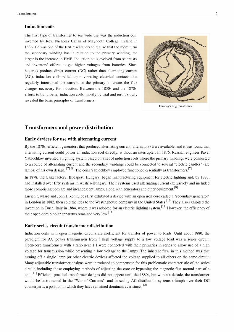
Faraday's ring transformer
The first type of transformer to see wide use was the induction coil,invented by Rev. Nicholas Callan of Maynooth College, Ireland in1836. He was one of the first researchers to realize that the more turnsthe secondary winding has in relation to the primary winding, thelarger is the increase in EMF. Induction coils evolved from scientists'and inventors' efforts to get higher voltages from batteries. Sincebatteries produce direct current (DC) rather than alternating current(AC), induction coils relied upon vibrating electrical contacts thatregularly interrupted the current in the primary to create the fluxchanges necessary for induction. Between the 1830s and the 1870s,efforts to build better induction coils, mostly by trial and error, slowlyrevealed the basic principles of transformers.
Transformers and power distribution
Early devices for use with alternating currentBy the 1870s, efficient generators that produced alternating current (alternators) were available, and it was found thatalternating current could power an induction coil directly, without an interrupter. In 1876, Russian engineer PavelYablochkov invented a lighting system based on a set of induction coils where the primary windings were connectedto a source of alternating current and the secondary windings could be connected to several "electric candles" (arclamps) of his own design. [7] [8] The coils Yablochkov employed functioned essentially as transformers.[7]
In 1878, the Ganz factory, Budapest, Hungary, began manufacturing equipment for electric lighting and, by 1883,had installed over fifty systems in Austria-Hungary. Their systems used alternating current exclusively and includedthose comprising both arc and incandescent lamps, along with generators and other equipment.[9]
Lucien Gaulard and John Dixon Gibbs first exhibited a device with an open iron core called a "secondary generator"in London in 1882, then sold the idea to the Westinghouse company in the United States.[10] They also exhibited theinvention in Turin, Italy in 1884, where it was adopted for an electric lighting system.[11] However, the efficiency oftheir open-core bipolar apparatus remained very low.[11]
Early series circuit transformer distributionInduction coils with open magnetic circuits are inefficient for transfer of power to loads. Until about 1880, theparadigm for AC power transmission from a high voltage supply to a low voltage load was a series circuit.Open-core transformers with a ratio near 1:1 were connected with their primaries in series to allow use of a highvoltage for transmission while presenting a low voltage to the lamps. The inherent flaw in this method was thatturning off a single lamp (or other electric device) affected the voltage supplied to all others on the same circuit.Many adjustable transformer designs were introduced to compensate for this problematic characteristic of the seriescircuit, including those employing methods of adjusting the core or bypassing the magnetic flux around part of acoil.[11] Efficient, practical transformer designs did not appear until the 1880s, but within a decade, the transformerwould be instrumental in the "War of Currents", and in seeing AC distribution systems triumph over their DCcounterparts, a position in which they have remained dominant ever since.[12]
Transformer 3
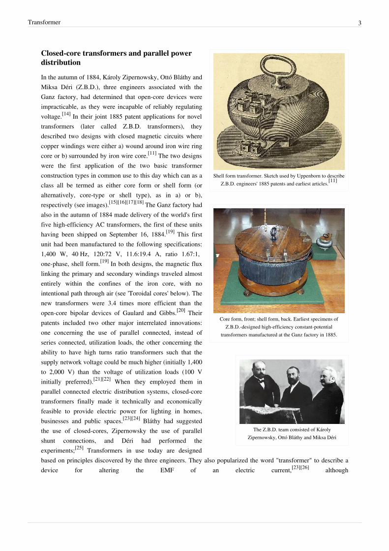
Shell form transformer. Sketch used by Uppenborn to describeZ.B.D. engineers' 1885 patents and earliest articles.[11]
Core form, front; shell form, back. Earliest specimens ofZ.B.D.-designed high-efficiency constant-potential
transformers manufactured at the Ganz factory in 1885.
The Z.B.D. team consisted of KárolyZipernowsky, Ottó Bláthy and Miksa Déri
Closed-core transformers and parallel powerdistribution
In the autumn of 1884, Károly Zipernowsky, Ottó Bláthy andMiksa Déri (Z.B.D.), three engineers associated with theGanz factory, had determined that open-core devices wereimpracticable, as they were incapable of reliably regulatingvoltage.[14] In their joint 1885 patent applications for noveltransformers (later called Z.B.D. transformers), theydescribed two designs with closed magnetic circuits wherecopper windings were either a) wound around iron wire ringcore or b) surrounded by iron wire core.[11] The two designswere the first application of the two basic transformerconstruction types in common use to this day which can as aclass all be termed as either core form or shell form (oralternatively, core-type or shell type), as in a) or b),respectively (see images).[15][16][17][18] The Ganz factory hadalso in the autumn of 1884 made delivery of the world's firstfive high-efficiency AC transformers, the first of these unitshaving been shipped on September 16, 1884.[19] This firstunit had been manufactured to the following specifications:1,400 W, 40 Hz, 120:72 V, 11.6:19.4 A, ratio 1.67:1,one-phase, shell form.[19] In both designs, the magnetic fluxlinking the primary and secondary windings traveled almostentirely within the confines of the iron core, with nointentional path through air (see 'Toroidal cores' below). Thenew transformers were 3.4 times more efficient than theopen-core bipolar devices of Gaulard and Gibbs.[20] Theirpatents included two other major interrelated innovations:one concerning the use of parallel connected, instead ofseries connected, utilization loads, the other concerning theability to have high turns ratio transformers such that thesupply network voltage could be much higher (initially 1,400to 2,000 V) than the voltage of utilization loads (100 Vinitially preferred).[21][22] When they employed them inparallel connected electric distribution systems, closed-coretransformers finally made it technically and economicallyfeasible to provide electric power for lighting in homes,businesses and public spaces.[23][24] Bláthy had suggestedthe use of closed-cores, Zipernowsky the use of parallelshunt connections, and Déri had performed theexperiments;[25] Transformers in use today are designedbased on principles discovered by the three engineers. They also popularized the word "transformer" to describe adevice for altering the EMF of an electric current,[23][26] although
Transformer 4
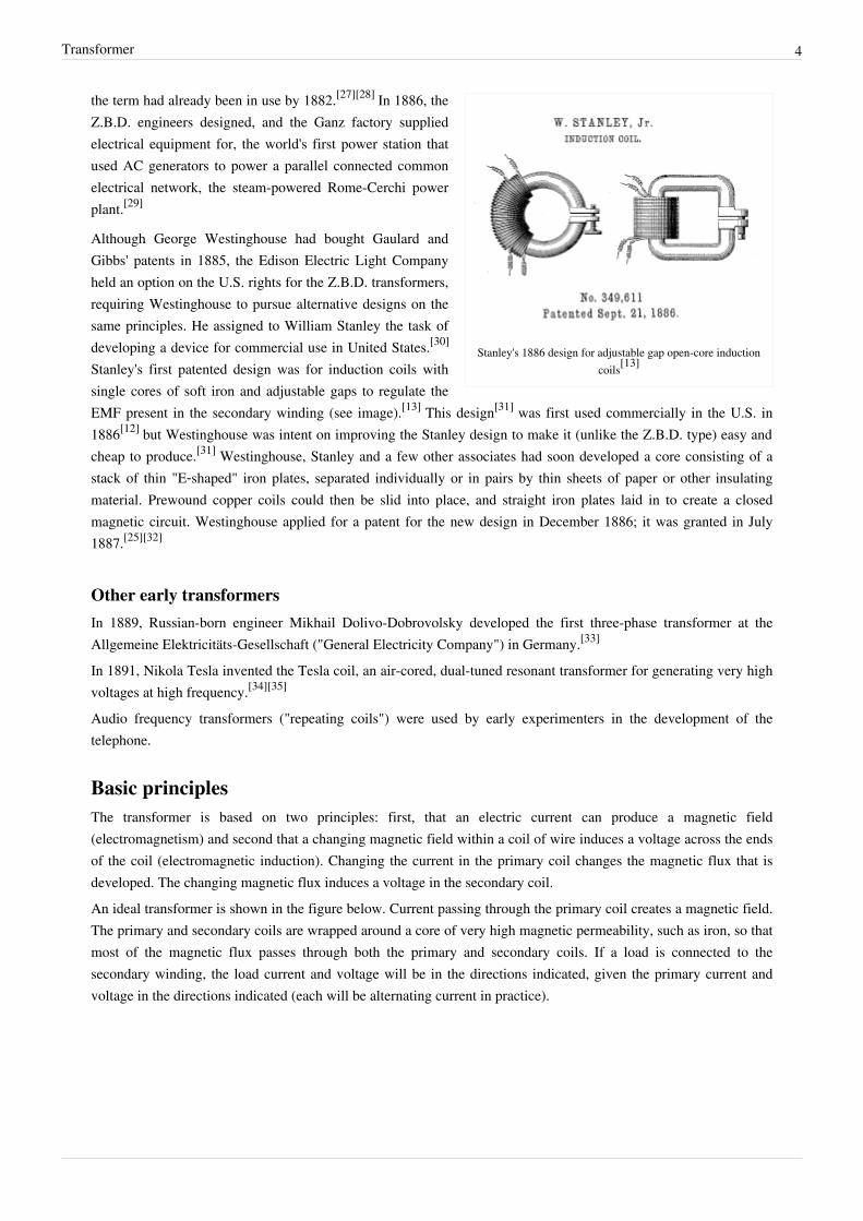
Stanley's 1886 design for adjustable gap open-core inductioncoils[13]
the term had already been in use by 1882.[27][28] In 1886, theZ.B.D. engineers designed, and the Ganz factory suppliedelectrical equipment for, the world's first power station thatused AC generators to power a parallel connected commonelectrical network, the steam-powered Rome-Cerchi powerplant.[29]
Although George Westinghouse had bought Gaulard andGibbs' patents in 1885, the Edison Electric Light Companyheld an option on the U.S. rights for the Z.B.D. transformers,requiring Westinghouse to pursue alternative designs on thesame principles. He assigned to William Stanley the task ofdeveloping a device for commercial use in United States.[30]
Stanley's first patented design was for induction coils withsingle cores of soft iron and adjustable gaps to regulate theEMF present in the secondary winding (see image).[13] This design[31] was first used commercially in the U.S. in1886[12] but Westinghouse was intent on improving the Stanley design to make it (unlike the Z.B.D. type) easy andcheap to produce.[31] Westinghouse, Stanley and a few other associates had soon developed a core consisting of astack of thin "E‑shaped" iron plates, separated individually or in pairs by thin sheets of paper or other insulatingmaterial. Prewound copper coils could then be slid into place, and straight iron plates laid in to create a closedmagnetic circuit. Westinghouse applied for a patent for the new design in December 1886; it was granted in July1887.[25][32]
Other early transformersIn 1889, Russian-born engineer Mikhail Dolivo-Dobrovolsky developed the first three-phase transformer at theAllgemeine Elektricitäts-Gesellschaft ("General Electricity Company") in Germany.[33]
In 1891, Nikola Tesla invented the Tesla coil, an air-cored, dual-tuned resonant transformer for generating very highvoltages at high frequency.[34][35]
Audio frequency transformers ("repeating coils") were used by early experimenters in the development of thetelephone.
Basic principlesThe transformer is based on two principles: first, that an electric current can produce a magnetic field(electromagnetism) and second that a changing magnetic field within a coil of wire induces a voltage across the endsof the coil (electromagnetic induction). Changing the current in the primary coil changes the magnetic flux that isdeveloped. The changing magnetic flux induces a voltage in the secondary coil.An ideal transformer is shown in the figure below. Current passing through the primary coil creates a magnetic field.The primary and secondary coils are wrapped around a core of very high magnetic permeability, such as iron, so thatmost of the magnetic flux passes through both the primary and secondary coils. If a load is connected to thesecondary winding, the load current and voltage will be in the directions indicated, given the primary current andvoltage in the directions indicated (each will be alternating current in practice).
Transformer 5
Induction law
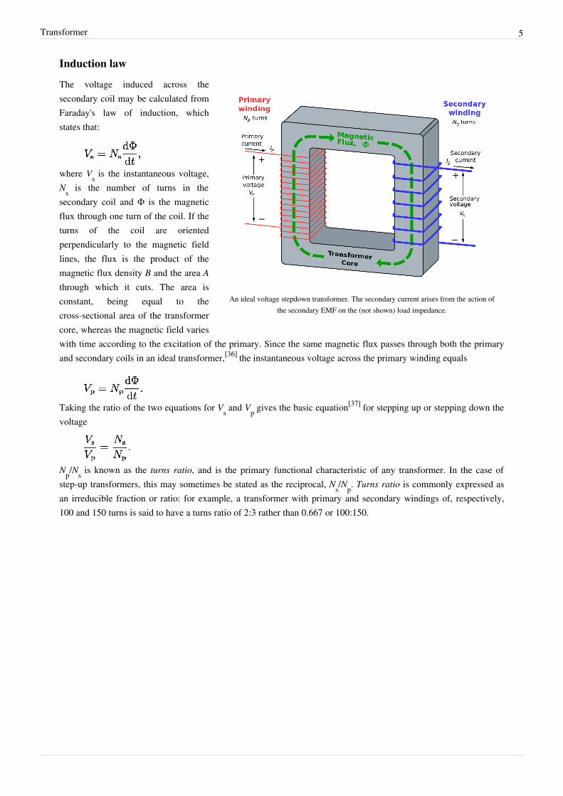
An ideal voltage stepdown transformer. The secondary current arises from the action ofthe secondary EMF on the (not shown) load impedance.
The voltage induced across thesecondary coil may be calculated fromFaraday's law of induction, whichstates that:
where Vs is the instantaneous voltage,Ns is the number of turns in thesecondary coil and Φ is the magneticflux through one turn of the coil. If theturns of the coil are orientedperpendicularly to the magnetic fieldlines, the flux is the product of themagnetic flux density B and the area Athrough which it cuts. The area isconstant, being equal to thecross-sectional area of the transformercore, whereas the magnetic field varieswith time according to the excitation of the primary. Since the same magnetic flux passes through both the primaryand secondary coils in an ideal transformer,[36] the instantaneous voltage across the primary winding equals
Taking the ratio of the two equations for Vs and Vp gives the basic equation[37] for stepping up or stepping down thevoltage
Np/Ns is known as the turns ratio, and is the primary functional characteristic of any transformer. In the case ofstep-up transformers, this may sometimes be stated as the reciprocal, Ns/Np. Turns ratio is commonly expressed asan irreducible fraction or ratio: for example, a transformer with primary and secondary windings of, respectively,100 and 150 turns is said to have a turns ratio of 2:3 rather than 0.667 or 100:150.

Transformer 6
Ideal power equation
The ideal transformer as a circuit element
If a load is connected to the secondary winding,current will flow in this winding, and electricalenergy will be transferred from the primarycircuit through the transformer to the load.Transformers may be used for AC-to-ACconversion of a single power frequency, or forconversion of signal power over a wide range offrequencies, such as audio or radio frequencies.
In an ideal transformer, the induced voltage inthe secondary winding (Vs) is in proportion tothe primary voltage (Vp) and is given by the ratioof the number of turns in the secondary (Ns) tothe number of turns in the primary (Np) asfollows:
By appropriate selection of the ratio of turns, a transformer thus enables an alternating current (AC) voltage to be"stepped up" by making Ns greater than Np, or "stepped down" by making Ns less than Np. The windings are coilswound around a ferromagnetic core, air-core transformers being a notable exception.
If the secondary coil is attached to a load that allows current to flow, electrical power is transmitted from the primarycircuit to the secondary circuit. Ideally, the transformer is perfectly efficient. All the incoming energy is transformedfrom the primary circuit to the magnetic field and into the secondary circuit. If this condition is met, the inputelectric power must equal the output power:
giving the ideal transformer equation
This formula is a reasonable approximation for commercial transformers.If the voltage is increased, then the current is decreased by the same factor. The impedance in one circuit istransformed by the square of the turns ratio.[36] For example, if an impedance Zs is attached across the terminals ofthe secondary coil, it appears to the primary circuit to have an impedance of (Np/Ns)
2Zs. This relationship isreciprocal, so that the impedance Zp of the primary circuit appears to the secondary to be (Ns/Np)2Zp.The ideal model neglects the primary current required to establish a magnetic field in the core, equivalent toassuming the core has negligible reluctance. Since the field generated in the core by current in the secondary windingopposes the field of the primary winding, current in the primary winding must increase to maintain the samerelationship between induced EMFs. The simple approximation also neglect the non-zero resistance of the twowindings.[38]
When a voltage is applied to the primary winding, a small current flows, driving flux around the magnetic circuit ofthe core.:[38] The current required to create the flux is termed the magnetizing current. Since the ideal core has beenassumed to have near-zero reluctance, the magnetizing current is negligible, although still required, to create themagnetic field.The changing magnetic field induces an electromotive force (EMF) across each winding.[39] Since the ideal windings have no impedance, they have no associated voltage drop, and so the voltages VP and VS measured at the terminals
Transformer 7
of the transformer, are equal to the corresponding EMFs. The primary EMF, acting as it does in opposition to theprimary voltage, is sometimes termed the "back EMF".[40] This is in accordance with Lenz's law, which states thatinduction of EMF always opposes development of any such change in magnetic field.
Basic transformer parameters and construction
Leakage flux
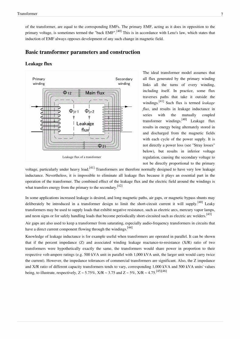
Leakage flux of a transformer
The ideal transformer model assumes thatall flux generated by the primary windinglinks all the turns of every winding,including itself. In practice, some fluxtraverses paths that take it outside thewindings.[41] Such flux is termed leakageflux, and results in leakage inductance inseries with the mutually coupledtransformer windings.[40] Leakage fluxresults in energy being alternately stored inand discharged from the magnetic fieldswith each cycle of the power supply. It isnot directly a power loss (see "Stray losses"below), but results in inferior voltageregulation, causing the secondary voltage tonot be directly proportional to the primary
voltage, particularly under heavy load.[41] Transformers are therefore normally designed to have very low leakageinductance. Nevertheless, it is impossible to eliminate all leakage flux because it plays an essential part in theoperation of the transformer. The combined effect of the leakage flux and the electric field around the windings iswhat transfers energy from the primary to the secondary.[42]
In some applications increased leakage is desired, and long magnetic paths, air gaps, or magnetic bypass shunts maydeliberately be introduced in a transformer design to limit the short-circuit current it will supply.[40] Leakytransformers may be used to supply loads that exhibit negative resistance, such as electric arcs, mercury vapor lamps,and neon signs or for safely handling loads that become periodically short-circuited such as electric arc welders.[43]
Air gaps are also used to keep a transformer from saturating, especially audio-frequency transformers in circuits thathave a direct current component flowing through the windings.[44]
Knowledge of leakage inductance is for example useful when transformers are operated in parallel. It can be shownthat if the percent impedance (Z) and associated winding leakage reactance-to-resistance (X/R) ratio of twotransformers were hypothetically exactly the same, the transformers would share power in proportion to theirrespective volt-ampere ratings (e.g. 500 kVA unit in parallel with 1,000 kVA unit, the larger unit would carry twicethe current). However, the impedance tolerances of commercial transformers are significant. Also, the Z impedanceand X/R ratio of different capacity transformers tends to vary, corresponding 1,000 kVA and 500 kVA units' valuesbeing, to illustrate, respectively, Z ~ 5.75%, X/R ~ 3.75 and Z ~ 5%, X/R ~ 4.75.[45][46]

Transformer 8
Effect of frequencyTransformer universal EMF equation
If the flux in the core is purely sinusoidal, the relationship for either winding between its rms voltage Erms of thewinding, and the supply frequency f, number of turns N, core cross-sectional area a and peak magnetic flux density Bis given by the universal EMF equation:[38]
If the flux does not contain even harmonics the following equation can be used for half-cycle average voltage Eavgof any waveshape:
The time-derivative term in Faraday's Law shows that the flux in the core is the integral with respect to time of theapplied voltage.[47] Hypothetically an ideal transformer would work with direct-current excitation, with the core fluxincreasing linearly with time.[48] In practice, the flux rises to the point where magnetic saturation of the core occurs,causing a large increase in the magnetizing current and overheating the transformer. All practical transformers musttherefore operate with alternating (or pulsed direct) current.[48]
The EMF of a transformer at a given flux density increases with frequency.[38] By operating at higher frequencies,transformers can be physically more compact because a given core is able to transfer more power without reachingsaturation and fewer turns are needed to achieve the same impedance. However, properties such as core loss andconductor skin effect also increase with frequency. Aircraft and military equipment employ 400 Hz power supplieswhich reduce core and winding weight.[49] Conversely, frequencies used for some railway electrification systemswere much lower (e.g. 16.7 Hz and 25 Hz) than normal utility frequencies (50 – 60 Hz) for historical reasonsconcerned mainly with the limitations of early electric traction motors. As such, the transformers used to step downthe high over-head line voltages (e.g. 15 kV) were much heavier for the same power rating than those designed onlyfor the higher frequencies.Operation of a transformer at its designed voltage but at a higher frequency than intended will lead to reducedmagnetizing current. At a lower frequency, the magnetizing current will increase. Operation of a transformer at otherthan its design frequency may require assessment of voltages, losses, and cooling to establish if safe operation ispractical. For example, transformers may need to be equipped with "volts per hertz" over-excitation relays to protectthe transformer from overvoltage at higher than rated frequency.One example of state-of-the-art design is traction transformers used for electric multiple unit and high speed trainservice operating across the,country border and using different electrical standards, such transformers' beingrestricted to be positioned below the passenger compartment. The power supply to, and converter equipment beingsupply by, such traction transformers have to accommodate different input frequencies and voltage (ranging from ashigh as 50 Hz down to 16.7 Hz and rated up to 25 kV) while being suitable for multiple AC asynchronous motor andDC converters & motors with varying harmonics mitigation filtering requirements.Knowledge of natural frequencies of transformer windings is necessary for the determination of winding transientresponse and switching surge voltages.
Transformer 9
Energy lossesAn ideal transformer would have no energy losses, and would be 100% efficient. In practical transformers, energy isdissipated in the windings, core, and surrounding structures. Larger transformers are generally more efficient, andthose rated for electricity distribution usually perform better than 98%.[50]
Experimental transformers using superconducting windings achieve efficiencies of 99.85%.[51] The increase inefficiency can save considerable energy, and hence money, in a large heavily loaded transformer; the trade-off is inthe additional initial and running cost of the superconducting design.Losses in transformers (excluding associated circuitry) vary with load current, and may be expressed as "no-load" or"full-load" loss. Winding resistance dominates load losses, whereas hysteresis and eddy current losses contribute toover 99% of the no-load loss. The no-load loss can be significant, so that even an idle transformer constitutes a drainon the electrical supply and a running cost. Designing transformers for lower loss requires a larger core, good-qualitysilicon steel, or even amorphous steel for the core and thicker wire, increasing initial cost so that there is a trade-offbetween initial cost and running cost (also see energy efficient transformer).[52]
Transformer losses arise from:Winding joule losses
Current flowing through winding conductors causes joule heating. As frequency increases, Skin effect andproximity effect causes winding resistance and, hence, losses to increase.
Core lossesHysteresis losses
Each time the magnetic field is reversed, a small amount of energy is lost due to hysteresis within thecore. For a given core material, the loss is proportional to the frequency, and is a function of the peakflux density to which it is subjected.[52]
Eddy current losses
Ferromagnetic materials are also good conductors and a core made from such a material also constitutesa single short-circuited turn throughout its entire length. Eddy currents therefore circulate within thecore in a plane normal to the flux, and are responsible for resistive heating of the core material. Theeddy current loss is a complex function of the square of supply frequency and inverse square of thematerial thickness.[52] Eddy current losses can be reduced by making the core of a stack of plateselectrically insulated from each other, rather than a solid block; all transformers operating at lowfrequencies use laminated or similar cores.
Magnetostriction related losses
Magnetic flux in a ferromagnetic material, such as the core, causes it to physically expand and contract slightlywith each cycle of the magnetic field, an effect known as magnetostriction. This produces the buzzing soundcommonly associated with transformers[37] that can cause losses due to frictional heating. This buzzing isparticularly familiar from low-frequency (50 Hz or 60 Hz) mains hum, and high-frequency (15,734 Hz(NTSC) or 15,625 Hz (PAL)) CRT noise.
Stray losses
Leakage inductance is by itself largely lossless, since energy supplied to its magnetic fields is returned to thesupply with the next half-cycle. However, any leakage flux that intercepts nearby conductive materials such asthe transformer's support structure will give rise to eddy currents and be converted to heat..[53] There are alsoradiative losses due to the oscillating magnetic field but these are usually small.
Mechanical losses
In addition to magnetostriction, the alternating magnetic field causes fluctuating forces between the primary and secondary windings. These incite vibrations within nearby metalwork, adding to the buzzing noise and

Transformer 10
consuming a small amount of power.[54]
Dot conventionIt is common in transformer schematic symbols for there to be a dot at the end of each coil within a transformer,particularly for transformers with multiple primary and secondary windings. The dots indicate the direction of eachwinding relative to the others. Voltages at the dot end of each winding are in phase; current flowing into the dot endof a primary coil will result in current flowing out of the dot end of a secondary coil.
Core form and shell form transformers
Core form = core type; shell form = shell type
Closed-core transformers are constructed in "core form" or"shell form". When windings surround the core, thetransformer is core form; when windings are surrounded bythe core, the transformer is shell form. Shell form designmay be more prevalent than core form design for distributiontransformer applications due to the relative ease in stackingthe core around winding coils.[15] Core form design tends to,as a general rule, be more economical, and therefore moreprevalent, than shell form design for high voltage powertransformer applications at the lower end of their voltage andpower rating ranges (less than or equal to, nominally, 230 kVor 75 MVA). At higher voltage and power ratings, shell formtransformers tend to be more prevalent.[15][18][55][56] Shellform design tends to be preferred for extra high voltage andhigher MVA applications because, though more laborintensive to manufacture, shell form transformers are characterized as having inherently better kVA-to-weight ratio,better short-circuit strength characteristics and higher immunity to transit damage.[56]
Equivalent circuitReferring to the diagram, a practical transformer's physical behavior may be represented by an equivalent circuitmodel, which can incorporate an ideal transformer.[57]
Winding joule losses and leakage reactances are represented by the following series loop impedances of the model:• Primary winding: RP, XP• Secondary winding: RS, XS.RS and XS are in practice usually referred to the primary side by multiplying these impedances by the scaling factor(NP/NS) 2.
Transformer equivalent circuit, with secondary impedances referred to the primary side
Core loss and reactance is representedby the following shunt leg impedancesof the model:• Core or iron losses: RC• Magnetizing reactance: XM.RC and XM are sometimes collectivelytermed the magnetizing branch of themodel.
Transformer 11
Core losses are caused mostly by hysteresis and eddy current effects in the core and are proportional to the square ofthe core flux for operation at a given frequency.[58] The finite permeability core requires a magnetizing current IM tomaintain mutual flux in the core. Magnetizing current is in phase with the flux, the relationship between the twobeing non-linear due to saturation effects. However, all impedances of the equivalent circuit shown are by definitionlinear and such non-linearity effects are not typically reflected in transformer equivalent circuits.[58] With sinusoidalsupply, core flux lags the induced EMF by 90°. With open-circuited secondary winding, magnetizing branch currentI0 equals transformer no-load current.[57]
The resulting model, though sometimes termed 'exact' equivalent circuit based on linearity assumptions, retains anumber of approximations.[57] Analysis may be simplified by assuming that magnetizing branch impedance isrelatively high and relocating the branch to the left of the primary impedances, thus allowing combination of primaryand referred secondary resistances and reactances by simple summation as two series impedances.Transformer equivalent circuit impedance and transformer ratio parameters can be derived from the following tests:Open-circuit test, short-circuit test, winding resistance test, and transformer ratio test.
Construction
Cores
Laminated steel cores
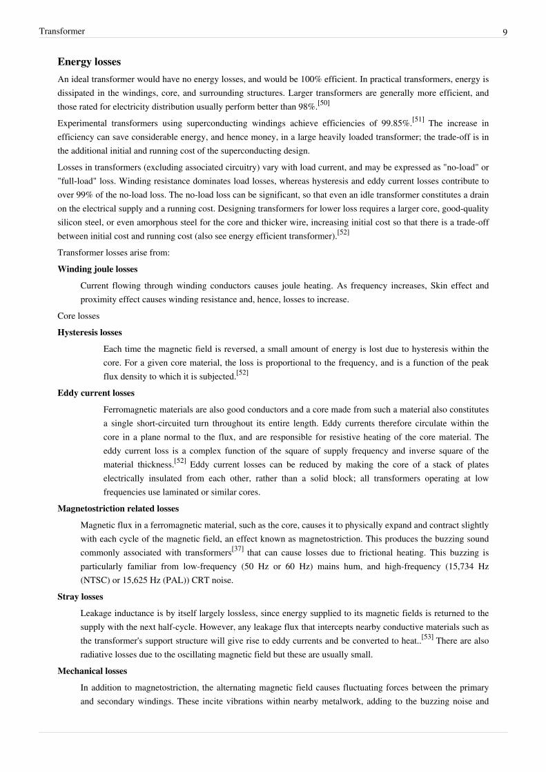
Laminated core transformer showing edge of laminations attop of photo
Transformers for use at power or audio frequencies typicallyhave cores made of high permeability silicon steel.[59] Thesteel has a permeability many times that of free space and thecore thus serves to greatly reduce the magnetizing current andconfine the flux to a path which closely couples thewindings.[60] Early transformer developers soon realized thatcores constructed from solid iron resulted in prohibitiveeddy-current losses, and their designs mitigated this effectwith cores consisting of bundles of insulated iron wires.[10]
Later designs constructed the core by stacking layers of thinsteel laminations, a principle that has remained in use. Eachlamination is insulated from its neighbors by a thinnon-conducting layer of insulation.[61] The universaltransformer equation indicates a minimum cross-sectional area for the core to avoid saturation.
The effect of laminations is to confine eddy currents to highly elliptical paths that enclose little flux, and so reducetheir magnitude. Thinner laminations reduce losses,[62] but are more laborious and expensive to construct.[63] Thinlaminations are generally used on high frequency transformers, with some types of very thin steel laminations able tooperate up to 10 kHz.

Transformer 12
Laminating the core greatly reduces eddy-current losses
One common design of laminated core is made frominterleaved stacks of E-shaped steel sheets capped withI-shaped pieces, leading to its name of "E-I transformer".[63]
Such a design tends to exhibit more losses, but is veryeconomical to manufacture. The cut-core or C-core type ismade by winding a steel strip around a rectangular form andthen bonding the layers together. It is then cut in two, formingtwo C shapes, and the core assembled by binding the two Chalves together with a steel strap.[63] They have the advantagethat the flux is always oriented parallel to the metal grains,reducing reluctance.
A steel core's remanence means that it retains a staticmagnetic field when power is removed. When power is thenreapplied, the residual field will cause a high inrush current
until the effect of the remaining magnetism is reduced, usually after a few cycles of the applied alternatingcurrent.[64] Overcurrent protection devices such as fuses must be selected to allow this harmless inrush to pass. Ontransformers connected to long, overhead power transmission lines, induced currents due to geomagneticdisturbances during solar storms can cause saturation of the core and operation of transformer protection devices.[65]
Distribution transformers can achieve low no-load losses by using cores made with low-loss high-permeabilitysilicon steel or amorphous (non-crystalline) metal alloy. The higher initial cost of the core material is offset over thelife of the transformer by its lower losses at light load.[66]
Solid cores
Powdered iron cores are used in circuits such as switch-mode power supplies that operate above mains frequenciesand up to a few tens of kilohertz. These materials combine high magnetic permeability with high bulk electricalresistivity. For frequencies extending beyond the VHF band, cores made from non-conductive magnetic ceramicmaterials called ferrites are common.[63] Some radio-frequency transformers also have movable cores (sometimescalled 'slugs') which allow adjustment of the coupling coefficient (and bandwidth) of tuned radio-frequency circuits.
Toroidal cores
Small toroidal core transformer
Toroidal transformers are built around a ring-shaped core, which,depending on operating frequency, is made from a long strip of siliconsteel or permalloy wound into a coil, powdered iron, or ferrite.[67] Astrip construction ensures that the grain boundaries are optimallyaligned, improving the transformer's efficiency by reducing the core'sreluctance. The closed ring shape eliminates air gaps inherent in theconstruction of an E-I core.[43] The cross-section of the ring is usuallysquare or rectangular, but more expensive cores with circularcross-sections are also available. The primary and secondary coils areoften wound concentrically to cover the entire surface of the core. Thisminimizes the length of wire needed, and also provides screening tominimize the core's magnetic field from generating electromagneticinterference.
Toroidal transformers are more efficient than the cheaper laminated E-I types for a similar power level. Other advantages compared to E-I types, include smaller size (about half), lower weight (about half), less mechanical hum
Transformer 13
(making them superior in audio amplifiers), lower exterior magnetic field (about one tenth), low off-load losses(making them more efficient in standby circuits), single-bolt mounting, and greater choice of shapes. The maindisadvantages are higher cost and limited power capacity (see "Classification" above). Because of the lack of aresidual gap in the magnetic path, toroidal transformers also tend to exhibit higher inrush current, compared tolaminated E-I types.Ferrite toroidal cores are used at higher frequencies, typically between a few tens of kilohertz to hundreds ofmegahertz, to reduce losses, physical size, and weight of inductive components. A drawback of toroidal transformerconstruction is the higher labor cost of winding. This is because it is necessary to pass the entire length of a coilwinding through the core aperture each time a single turn is added to the coil. As a consequence, toroidaltransformers rated more than a few kVA are uncommon. Small distribution transformers may achieve some of thebenefits of a toroidal core by splitting it and forcing it open, then inserting a bobbin containing primary andsecondary windings.
Air cores
A physical core is not an absolute requisite and a functioning transformer can be produced simply by placing thewindings near each other, an arrangement termed an "air-core" transformer. The air which comprises the magneticcircuit is essentially lossless, and so an air-core transformer eliminates loss due to hysteresis in the core material.[40]
The leakage inductance is inevitably high, resulting in very poor regulation, and so such designs are unsuitable foruse in power distribution.[40] They have however very high bandwidth, and are frequently employed inradio-frequency applications,[68] for which a satisfactory coupling coefficient is maintained by carefully overlappingthe primary and secondary windings. They're also used for resonant transformers such as Tesla coils where they canachieve reasonably low loss in spite of the high leakage inductance.
Windings
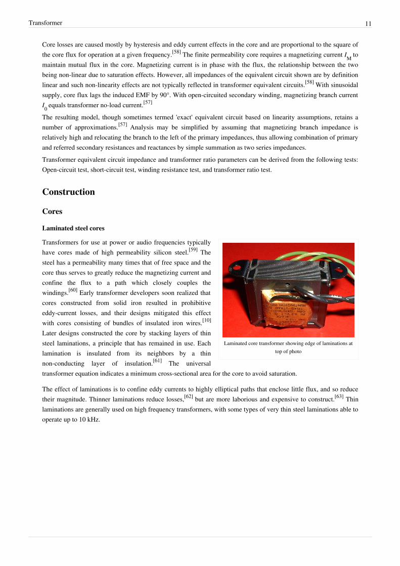
Windings are usually arranged concentrically to minimize fluxleakage.
The conducting material used for the windings dependsupon the application, but in all cases the individualturns must be electrically insulated from each other toensure that the current travels throughout every turn.[69]
For small power and signal transformers, in whichcurrents are low and the potential difference betweenadjacent turns is small, the coils are often wound fromenamelled magnet wire, such as Formvar wire. Largerpower transformers operating at high voltages may bewound with copper rectangular strip conductorsinsulated by oil-impregnated paper and blocks ofpressboard.[70]
Transformer 14
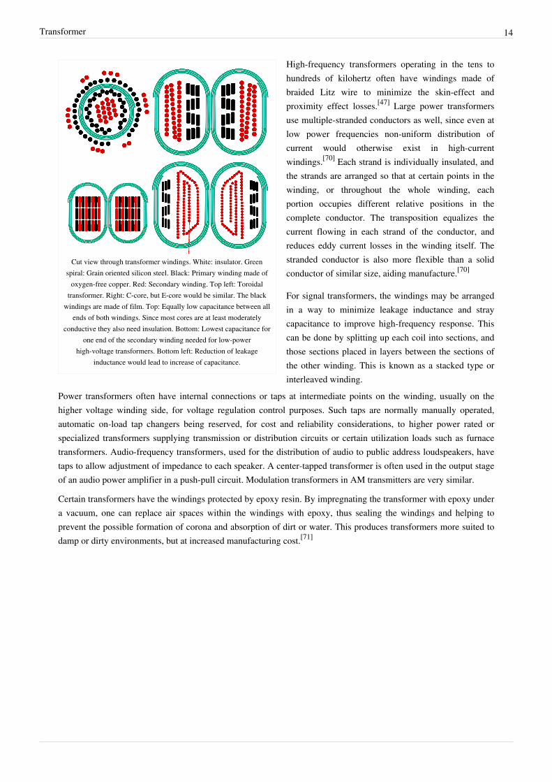
Cut view through transformer windings. White: insulator. Greenspiral: Grain oriented silicon steel. Black: Primary winding made of
oxygen-free copper. Red: Secondary winding. Top left: Toroidaltransformer. Right: C-core, but E-core would be similar. The black
windings are made of film. Top: Equally low capacitance between allends of both windings. Since most cores are at least moderately
conductive they also need insulation. Bottom: Lowest capacitance forone end of the secondary winding needed for low-power
high-voltage transformers. Bottom left: Reduction of leakageinductance would lead to increase of capacitance.
High-frequency transformers operating in the tens tohundreds of kilohertz often have windings made ofbraided Litz wire to minimize the skin-effect andproximity effect losses.[47] Large power transformersuse multiple-stranded conductors as well, since even atlow power frequencies non-uniform distribution ofcurrent would otherwise exist in high-currentwindings.[70] Each strand is individually insulated, andthe strands are arranged so that at certain points in thewinding, or throughout the whole winding, eachportion occupies different relative positions in thecomplete conductor. The transposition equalizes thecurrent flowing in each strand of the conductor, andreduces eddy current losses in the winding itself. Thestranded conductor is also more flexible than a solidconductor of similar size, aiding manufacture.[70]
For signal transformers, the windings may be arrangedin a way to minimize leakage inductance and straycapacitance to improve high-frequency response. Thiscan be done by splitting up each coil into sections, andthose sections placed in layers between the sections ofthe other winding. This is known as a stacked type orinterleaved winding.
Power transformers often have internal connections or taps at intermediate points on the winding, usually on thehigher voltage winding side, for voltage regulation control purposes. Such taps are normally manually operated,automatic on-load tap changers being reserved, for cost and reliability considerations, to higher power rated orspecialized transformers supplying transmission or distribution circuits or certain utilization loads such as furnacetransformers. Audio-frequency transformers, used for the distribution of audio to public address loudspeakers, havetaps to allow adjustment of impedance to each speaker. A center-tapped transformer is often used in the output stageof an audio power amplifier in a push-pull circuit. Modulation transformers in AM transmitters are very similar.
Certain transformers have the windings protected by epoxy resin. By impregnating the transformer with epoxy undera vacuum, one can replace air spaces within the windings with epoxy, thus sealing the windings and helping toprevent the possible formation of corona and absorption of dirt or water. This produces transformers more suited todamp or dirty environments, but at increased manufacturing cost.[71]
Transformer 15
Cooling
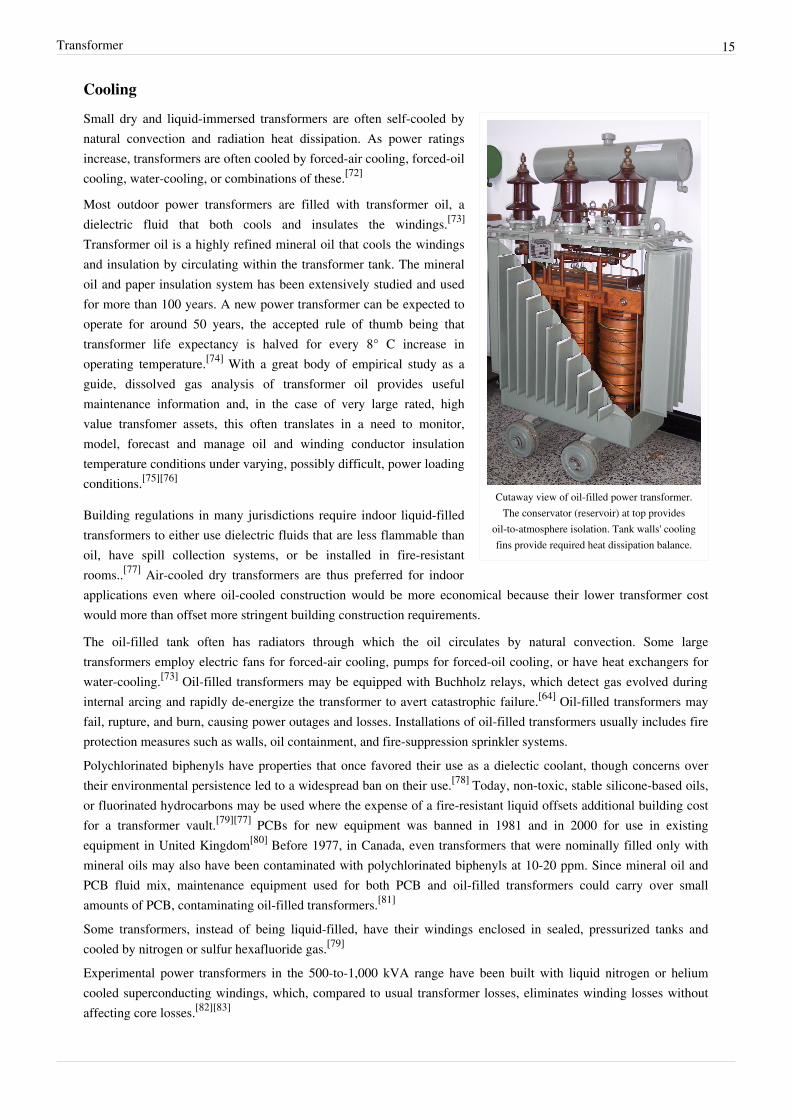
Cutaway view of oil-filled power transformer.The conservator (reservoir) at top provides
oil-to-atmosphere isolation. Tank walls' coolingfins provide required heat dissipation balance.
Small dry and liquid-immersed transformers are often self-cooled bynatural convection and radiation heat dissipation. As power ratingsincrease, transformers are often cooled by forced-air cooling, forced-oilcooling, water-cooling, or combinations of these.[72]
Most outdoor power transformers are filled with transformer oil, adielectric fluid that both cools and insulates the windings.[73]
Transformer oil is a highly refined mineral oil that cools the windingsand insulation by circulating within the transformer tank. The mineraloil and paper insulation system has been extensively studied and usedfor more than 100 years. A new power transformer can be expected tooperate for around 50 years, the accepted rule of thumb being thattransformer life expectancy is halved for every 8° C increase inoperating temperature.[74] With a great body of empirical study as aguide, dissolved gas analysis of transformer oil provides usefulmaintenance information and, in the case of very large rated, highvalue transfomer assets, this often translates in a need to monitor,model, forecast and manage oil and winding conductor insulationtemperature conditions under varying, possibly difficult, power loadingconditions.[75][76]
Building regulations in many jurisdictions require indoor liquid-filledtransformers to either use dielectric fluids that are less flammable thanoil, have spill collection systems, or be installed in fire-resistantrooms..[77] Air-cooled dry transformers are thus preferred for indoorapplications even where oil-cooled construction would be more economical because their lower transformer costwould more than offset more stringent building construction requirements.
The oil-filled tank often has radiators through which the oil circulates by natural convection. Some largetransformers employ electric fans for forced-air cooling, pumps for forced-oil cooling, or have heat exchangers forwater-cooling.[73] Oil-filled transformers may be equipped with Buchholz relays, which detect gas evolved duringinternal arcing and rapidly de-energize the transformer to avert catastrophic failure.[64] Oil-filled transformers mayfail, rupture, and burn, causing power outages and losses. Installations of oil-filled transformers usually includes fireprotection measures such as walls, oil containment, and fire-suppression sprinkler systems.Polychlorinated biphenyls have properties that once favored their use as a dielectic coolant, though concerns overtheir environmental persistence led to a widespread ban on their use.[78] Today, non-toxic, stable silicone-based oils,or fluorinated hydrocarbons may be used where the expense of a fire-resistant liquid offsets additional building costfor a transformer vault.[79][77] PCBs for new equipment was banned in 1981 and in 2000 for use in existingequipment in United Kingdom[80] Before 1977, in Canada, even transformers that were nominally filled only withmineral oils may also have been contaminated with polychlorinated biphenyls at 10-20 ppm. Since mineral oil andPCB fluid mix, maintenance equipment used for both PCB and oil-filled transformers could carry over smallamounts of PCB, contaminating oil-filled transformers.[81]
Some transformers, instead of being liquid-filled, have their windings enclosed in sealed, pressurized tanks andcooled by nitrogen or sulfur hexafluoride gas.[79]
Experimental power transformers in the 500-to-1,000 kVA range have been built with liquid nitrogen or heliumcooled superconducting windings, which, compared to usual transformer losses, eliminates winding losses withoutaffecting core losses.[82][83]

Transformer 16
Insulation dryingConstruction of oil-filled transformers requires that the insulation covering the windings be thoroughly dried beforethe oil is introduced. Drying is carried out at the factory, and may be required as a field service. Drying may be doneby circulating hot air around the core, or by vapour-phase drying (VPD) where evaporated solvent transfers heat bycondensation on the coil and core. For small transformers resistance heating by injection of current into the windingsis used. The heating can be controlled very well and it is energy efficient. The method is called low-frequencyheating (LFH) since the current is injected at a much lower frequency than the nominal of the grid, which is normally50 or 60 Hz. A lower frequency reduces the effect of the inductance in the transformer, so the voltage needed toinduce the current can be reduced.[84] The LFH drying method is also used for service of older transformers.[85]
TerminalsVery small transformers will have wire leads connected directly to the ends of the coils, and brought out to the baseof the unit for circuit connections. Larger transformers may have heavy bolted terminals, bus bars or high-voltageinsulated bushings made of polymers or porcelain. A large bushing can be a complex structure since it must providecareful control of the electric field gradient without letting the transformer leak oil.[86]
Classification parametersTransformers can be classified in many ways, such as the following:• Power capacity: From a fraction of a volt-ampere (VA) to over a thousand MVA.• Duty of a transformer: Continuous, short-time, intermittent, periodic, varying.• Frequency range: Power-frequency, audio-frequency, or radio-frequency.• Voltage class: From a few volts to hundreds of kilovolts.• Cooling type: Dry and liquid-immersed - self-cooled, forced air-cooled; liquid-immersed - forced oil-cooled,
water-cooled.• Circuit application: Such as power supply, impedance matching, output voltage and current stabilizer or circuit
isolation.• Utilization: Pulse, power distribution, rectifier, arc furnace, amplifier output, etc..• Basic magnetic form: Core form, shell form.• Constant-potential transformer descriptor: Step-up, step-down, isolation.• General winding configuration: By EIC vector group - various possible two-winding combinations of the phase
designations delta, wye or star, and zigzag or interconnected star;[87] other - autotransformer, Scott-T, zigzaggrounding transformer winding.[88][89][90][91]
• Rectifier phase-shift winding configuration: 2-winding, 6-pulse; 3-winding, 12-pulse; . . . n-winding,[n-1]*6-pulse; polygon; etc..
TypesFor more details, see Transformer types or specific main articles, as shown.A wide variety of transformer designs are used for different applications, though they share several commonfeatures. Important common transformer types include:• Autotransformer: Transformer in which part of the winding is common to both primary and secondary circuits.[92]
• Capacitor voltage transformer: Transformer in which capacitor divider is used to reduce high voltage beforeapplication to the primary winding.
• Distribution transformer: Transformer used to distribute energy from transmission lines and networks for localconsumption.[92]
• Scott-T transformer: Transformer used for phase transformation from three-phase to two-phase and vice versa.[92]

Transformer 17
• Polyphase transformer: Any transformer with more than one phase.• Zigzag or interconnected star transformer, zigzag grounding transformer winding: Transformer used for
grounding or phase-shifting three-phase circuits.• Leakage tramsformer: Transformer that has loosely coupled windings.• Resonant transformer: Transformer that uses resonance to generate a high secondary voltage.• Audio transformer: Transformer used in audio equipment.• Output transformer: Transformer used to match the output of a valve amplifer to its load.• Instrument transformer: Potential or current transformer used to accurately and safely represent voltage, current
or phase position of high voltage or high power circuits.[92]
Applications
An electrical substation in Melbourne, Australia showing 3 of 5 220kV/66kVtransformers, each with a capacity of 150 MVA.[93]
Transformer at the Limestone Generating Stationin Manitoba, Canada
Transformers are used to increase voltagebefore transmitting electrical energy overlong distances through wires. Wires haveresistance which loses energy through jouleheating at a rate corresponding to square ofthe current. By transforming electricalpower to a higher voltage for transmissionand transformers enable economicaltransmission of power and distribution.Consequently, transformers have shaped theelectricity supply industry, permittinggeneration to be located remotely frompoints of demand.[94] All but a tiny fractionof the world's electrical power has passedthrough a series of transformers by the timeit reaches the consumer.[53]
Transformers are also used extensively inelectronic products to step down the supplyvoltage to a level suitable for the lowvoltage circuits they contain. Thetransformer also electrically isolates the enduser from contact with the supply voltage.
Signal and audio transformers are used tocouple stages of amplifiers and to matchdevices such as microphones and recordplayers to the input of amplifiers. Audiotransformers allowed telephone circuits tocarry on a two-way conversation over asingle pair of wires. A balun transformer
converts a signal that is referenced to ground to a signal that has balanced voltages to ground, such as betweenexternal cables and internal circuits.
The principle of open-circuit (unloaded) transformer is widely used for characterisation of soft magnetic materials,for example in the internationally standardised Epstein frame method.[95]
Transformer 18
Notes[1] Knowlton, A.E. (Ed.) (1949). Standard Handbook for Electrical Engineers (8th ed.). McGraw-Hill. p. 597, Fig. 6-42.[2] Mack, James E.; Shoemaker, Thomas (2006). "Chapter 15 - Distribution Transformers" (http:/ / books. mcgraw-hill. com/ downloads/
products/ 0071467890/ 0071467890_ch15. pdf). The Lineman's and Cableman's Handbook (11th ed.). New York: McGraw-Hill. pp. 15-1 to15-22. ISBN 0071467890. .
[3] Poyser, Arthur William (1892). Magnetism and Electricity: A Manual for Students in Advanced Classes (http:/ / books. google. com/books?id=JzBAAAAAYAAJ& pg=PA285). London and New York: Longmans, Green, & Co.. p. 285, fig. 248. . Retrieved Aug. 6, 2009.
[4] "Joseph Henry" (http:/ / www. nas. edu/ history/ members/ henry. html). Distinguished Members Gallery, National Academy of Sciences. .Retrieved Nov. 30, 2006.
[5] Chow, Tai L. (2006). Introduction to Electromagnetic Theory: A Modern Perspective (http:/ / books. google. com/books?id=dpnpMhw1zo8C& pg=PA171& dq=isbn=0763738271+ "Time-Dependent+ Magnetic+ fields+ and+ Faraday's+ Law+ of+Induction"& cd=1#v=onepage& q=& f=false). Sudbury, Mass.: Jones and Bartlett Publishers. p. 171. ISBN 0-7637-3827-1. .
[6] Faraday, Michael (1834). "Experimental Researches on Electricity, 7th Series". Philosophical Transactions of the Royal Society of London124: 77–122. doi:10.1098/rstl.1834.0008.
[7] "Stanley Transformer" (http:/ / www. magnet. fsu. edu/ education/ tutorials/ museum/ stanleytransformer. html). Los Alamos NationalLaboratory; University of Florida. . Retrieved Jan. 9, 2009.
[8] De Fonveille, W. (Jan. 22, 1880). "Gas and Electricity in Paris" (http:/ / books. google. com/ ?id=ksa-S7C8dT8C& pg=RA2-PA283). Nature21 (534): 283. . Retrieved Jan. 9, 2009.
[9] Hughes, Thomas P. (1993). Networks of Power: Electrification in Western Society, 1880-1930 (http:/ / books. google. com/?id=g07Q9M4agp4C& pg=PA96& dq=Networks+ of+ Power:+ Electrification+ in+ Western+ Society,+ 1880-1930+ ganz#v=onepage& q=).Baltimore: The Johns Hopkins University Press. p. 96. ISBN 0-8018-2873-2. . Retrieved Sep. 9, 2009.
[10] Allan, D.J. (Jan. 1991). "Power Transformers – The Second Century" (http:/ / ieeexplore. ieee. org/ xpl/ freeabs_all. jsp?arnumber=61984).Power Engineering Journal 5 (1): 5–14. .
[11] Uppenborn, F. J. (1889). History of the Transformer (http:/ / www. archive. org/ details/ historyoftransfo00upperich). London: E. & F. N.Spon. pp. 35–41. .
[12] Coltman, J. W. (Jan. 1988). "The Transformer". Scientific American: pp. 86–95. OSTI 6851152.[13] Stanley, William, Jr.. "Induction Coil" (http:/ / www. google. com/ patents?vid=349611). U.S. Patent 349 311, issued Sept. 21, 1886. .
Retrieved July 13, 2009.[14][14] Hughes, p. 95[15] Del Vecchio, Robert M. et al. (2002). Transformer Design Principles: With Applications to Core-Form Power Transformers (http:/ / books.
google. ca/ books/ about/ Transformer_design_principles. html?id=Lzjs0LNHhVYC& redir_esc=y). Boca Raton: CRC Press. pp. 10–11, Fig.1.8. ISBN 90-5699-703-3. .
[16] Károly, Simonyi. "The Faraday Law With a Magnetic Ohm's Law" (http:/ / www. termeszetvilaga. hu/ kulonsz/ k011/ 46. html). TermészetVilága. . Retrieved Mar. 1, 2012.
[17] Lucas, J.R.. "Historical Development of the Transformer" (http:/ / www. elect. mrt. ac. lk/ Transformer_history_2000. pdf). IEE Sri LankaCentre. . Retrieved Mar. 1, 2012.
[18][18] Knowlton, p. 562[19] Halacsy, A. A.; Von Fuchs, G. H. (April 1961). "Transformer Invented 75 Years Ago" (http:/ / ieeexplore. ieee. org/ search/ freesearchresult.
jsp?newsearch=true& queryText=10. 1109/ AIEEPAS. 1961. 4500994& x=29& y=16). IEEE Transactions of the American Institute ofElectrical Engineers 80 (3): 121–125. doi:10.1109/AIEEPAS.1961.4500994. . Retrieved Feb. 29, 2012.
[20] Jeszenszky, Sándor. "Electrostatics and Electrodynamics at Pest University in the Mid-19th Century" (http:/ / ppp. unipv. it/ Collana/ Pages/Libri/ Saggi/ Volta and the History of Electricity/ V& H Sect2/ V& H 175-182. pdf). University of Pavia. . Retrieved Mar.3, 2012.
[21] "Hungarian Inventors and Their Inventions" (http:/ / www. institutoideal. org/ conteudo_eng. php?& sys=biblioteca_eng& arquivo=1&artigo=94& ano=2008). Institute for Developing Alternative Energy in Latin America. . Retrieved Mar. 3, 2012.
[22] "Bláthy, Ottó Titusz" (http:/ / www. omikk. bme. hu/ archivum/ angol/ htm/ blathy_o. htm). Budapest University of Technology andEconomics, National Technical Information Centre and Library. . Retrieved Feb. 29, 2012.
[23] "Bláthy, Ottó Titusz (1860 - 1939)" (http:/ / www. hpo. hu/ English/ feltalalok/ blathy. html). Hungarian Patent Office. . Retrieved Jan. 29,2004.
[24] Zipernowsky, K.; Déri, M.; Bláthy, O.T.. "Induction Coil" (http:/ / www. freepatentsonline. com/ 0352105. pdf). U.S. Patent 352 105, issuedNov. 2, 1886. . Retrieved July 8, 2009.
[25] Smil, Vaclav (2005). Creating the Twentieth Century: Technical Innovations of 1867—1914 and Their Lasting Impact (http:/ / books.google. com/ books?id=w3Mh7qQRM-IC& pg=PA71& lpg=PA71& dq=ZBD+ transformer& source=bl& ots=HRDljDzbiz&sig=F-cGB0B8BjL32gIunSIvtSB5hYc& hl=en& ei=k7tXSpvIDoT-MPGahJ0I& sa=X& oi=book_result& ct=result& resnum=4). Oxford:Oxford University Press. p. 71. .
[26] Nagy, Árpád Zoltán (Oct. 11, 1996). "Lecture to Mark the 100th Anniversary of the Discovery of the Electron in 1897 (preliminary text)"(http:/ / www. kfki. hu/ ~aznagy/ lecture/ lecture. htm). Budapest. . Retrieved July 9, 2009.
[27] Oxford English Dictionary (2nd ed.). Oxford University Press. 1989.
Transformer 19
[28] Hospitalier, Édouard; as translated by Julius Maier (1882). The Modern Applications of Electricity (http:/ / books. google. com/books?id=qt8JAAAAIAAJ). New York: D. Appleton & Co.. p. 103. .
[29] "Ottó Bláthy, Miksa Déri, Károly Zipernowsky" (http:/ / www. iec. ch/ cgi-bin/ tl_to_htm. pl?section=technology& item=144). IECTechline. . Retrieved Apr. 16, 2010.
[30] Skrabec, Quentin R. (2007). George Westinghouse: Gentle Genius (http:/ / books. google. com/ ?id=C3GYdiFM41oC& pg=PA102). AlgoraPublishing. p. 102. ISBN 978-0-87586-508-9. .
[31] Coltman, J.W.; (Jan-Feb 2002). "The Transformer [Historical Overview (http:/ / ieeexplore. ieee. org/ xpls/ abs_all.jsp?arnumber=974352)"]. Industry Applications Magazine, IEEE 8 (1): 8–15. doi:10.1109/2943.974352. . Retrieved Feb. 29, 2012.
[32] Westinghouse, George, Jr.. "Electrical Converter" (http:/ / www. google. com/ patents/ about?id=NmRDAAAAEBAJ& dq=366362). U.S.Patent 366 362, issued July 12, 1887. .
[33] Neidhöfer, Gerhard; in collaboration with VDE "History of Electrical Engineering" Committee (2008) (in German). Michael vonDolivo-Dobrowolsky and Three-Phase: The Beginnings of Modern Drive Technology and Power Supply (http:/ / d-nb. info/ 990964361) (2ed.). Berlin: VDE-Verl.. ISBN 978-3-8007-3115-2. .
[34] Uth, Robert (Dec. 12, 2000). "Tesla Coil" (http:/ / www. pbs. org/ tesla/ ins/ lab_tescoil. html). Tesla: Master of Lightning. PBS.org. .Retrieved May 20, 2008.
[35] Tesla, Nikola. "System of Electrical Lighting" (http:/ / patft. uspto. gov/ netacgi/ nph-Parser?Sect1=PTO1& Sect2=HITOFF& d=PALL&p=1& u=/ netahtml/ PTO/ srchnum. htm& r=1& f=G& l=50& s1=0454622. PN. & OS=PN/ 0454622& RS=PN/ 0454622). U.S. Patent 454622, issued June 23, 1891. .
[36] Flanagan, William M. (1993). Handbook of Transformer Design & Applications (2nd ed.). McGraw-Hill. pp. 1-2. ISBN 0-07-021291-0.[37] Winders, John J., Jr. (2002). Power Transformer Principles and Applications. CRC. pp. 20–21.[38] Say, M. G. (1984). Alternating Current Machines (5th ed.). Halsted Press. ISBN 0-470-27451-4.[39] Heathcote, Martin (Nov. 3, 1998). J & P Transformer Book (12th ed.). Newnes. pp. 2–3. ISBN 0-7506-1158-8.[40] Calvert, James (2001). "Inside Transformers" (http:/ / www. du. edu/ ~jcalvert/ tech/ transfor. htm). University of Denver. . Retrieved May
19, 2007.[41] McLaren, P. G. (1984). Elementary Electric Power and Machines. pp. 68–74. ISBN 0-13-257601-5.[42] Edwards, J.; Saha, T. K. (2000). "Power Flow in Transformers Via the Poynting Vector" (http:/ / www. itee. uq. edu. au/ ~aupec/ aupec00/
edwards00. pdf). AUPEC 2000 Proceedings. Queensland University of Technology. .[43][43] Say, p. 485[44] Terman, Frederick E. (1955). Electronic and Radio Engineering (4th ed.). New York: McGraw-Hill. pp. 15.[45][45] Knowlton, p. 585-586[46] Haymeyer, Kay (2001). "Electrical Machines I: Basics, Design, Function, Operation" (http:/ / materialy. itc. pw. edu. pl/ zpnis/
electric_machines_I/ ForStudents/ Script_EMIHanneberger. pdf). RWTH Aachen University Institute of Electrical Machines. p. 39. .Retrieved 16 January 2013.
[47] Dixon, Lloyd (2001). "Power Transformer Design" (http:/ / focus. ti. com/ lit/ ml/ slup126/ slup126. pdf). Magnetics Design Handbook.Texas Instruments. .
[48] Billings, Keith (1999). Switchmode Power Supply Handbook. McGraw-Hill. ISBN 0-07-006719-8.[49] "400 Hz Electrical Systems" (http:/ / www. aerospaceweb. org/ question/ electronics/ q0219. shtml). Aerospaceweb.org. . Retrieved May 21,
2007.[50] Kubo, T.; Sachs, H.; Nadel, S. (2001). Opportunities for New Appliance and Equipment Efficiency Standards (http:/ / www. aceee. org/
research-report/ a016). American Council for an Energy-Efficient Economy. p. 39. . Retrieved June 21, 2009.[51] Riemersma, H.; Eckels, P.; Barton, M.; Murphy, J.; Litz, D.; Roach, J. (1981). "Application of Superconducting Technology to Power
Transformers" (http:/ / md1. csa. com/ partners/ viewrecord. php?requester=gs& collection=TRD& recid=0043264EA& q=superconducting+transformer& uid=790516502& setcookie=yes). IEEE Transactions on Power Apparatus and Systems PAS-100 (7): 3398.doi:10.1109/TPAS.1981.316682. .
[52][52] Heathcote, pp. 41-42[53] Nailen, Richard (May 2005). "Why We Must Be Concerned With Transformers" (http:/ / www. blnz. com/ news/ 2008/ 04/ 23/
must_concerned_with_transformers_9639. html). Electrical Apparatus. .[54] Pansini, Anthony J. (1999). Electrical Transformers and Power Equipment. Fairmont Press. p. 23. ISBN 0-88173-311-3.[55] Hydroelectric Research and Technical Services Group. "Transformers: Basics, Maintenance, and Diagnostics" (http:/ / permanent. access.
gpo. gov/ lps113746/ Trnsfrmr. pdf). U.S. Dept. of the Interior, Bureau of Reclamation. p. 12. . Retrieved Mar. 27, 2012.[56] EM 1110-2-3006 (1994). "Chapter 4 - Power Transformers" (http:/ / 140. 194. 76. 129/ publications/ eng-manuals/ em1110-2-3006/ c-4.
pdf). Engineering and Design - Hydroelectric Power Plants Electrical Design. U.S. Army Corps of Engineers. p. 4-1. .[57] Daniels, A. R.. Introduction to Electrical Machines. pp. 47–49.[58][58] Say, pp. 142-143[59] Hindmarsh, J. (1984). Electrical Machines and Their Applications.. Oxford: Pergamon Press. pp. 29–31. ISBN 0-08-030573-3.[60] Gottlieb, Irving (1998). Practical Transformer Handbook. Newnes. p. 4. ISBN 0-7506-3992-X.[61] Kulkarni, S. V.; Khaparde, S. A. (May 24, 2004). Transformer Engineering: Design and Practice. CRC. pp. 36–37. ISBN 0-8247-5653-3.[62][62] Hindmarsh, pp. 29-31[63] McLyman, Colonel Wm. T. (2004). Transformer and Inductor Design Handbook. CRC. Chap. 3, pp. 9–14. ISBN 0-8247-5393-3.

Transformer 20
[64] Harlow, James H. (Ed.) (2004). Electric Power Transformer Engineering. CRC/Taylor & Francis. Chap. 2, pp. 20–21.[65] Boteler, D. H.; Pirjola, R. J.; Nevanlinna, H. (1998). "The Effects of Geomagnetic Disturbances On Electrical Systems at the Earth's
Surface". Advances in Space Research 22: 17–27. doi:10.1016/S0273-1177(97)01096-X.[66] Hasegawa, Ryusuke (June 2, 2000). "Present Status of Amorphous Soft Magnetic Alloys". Journal of Magnetism and Magnetic Materials
215-216: 240–245. doi:10.1016/S0304-8853(00)00126-8.[67][67] McLyman, Chap. 3 p. 1[68] Lee, Reuben. "Air-Core Transformers" (http:/ / www. vias. org/ eltransformers/ lee_electronic_transformers_07b_22. html). Electronic
Transformers and Circuits. . Retrieved May 22, 2007.[69] Dixon, L.H., Jr. (1997). Eddy Current Losses in Transformer Windings (http:/ / focus. ti. com/ lit/ ml/ slup197/ slup197. pdf). Texas
Instrument. pp. R2-1-to-R2-10. .[70] Central Electricity Generating Board (1982). Modern Power Station Practice. Pergamon Press.[71] Heathcote, pp. 720–723[72][72] Pansini, p. 32[73] Willis, H. Lee (2004). Power Distribution Planning Reference Book. CRC Press. p. 403. ISBN 0-8247-4875-1.[74] Grigsby, L. L. (Ed.) (2001). "Chapter 3 - Transformers by James H. Harlow". The Electric Power Engineering Handbook ([Online-Ausg.]
ed.). Boca Raton, FL: CRC Press. pp. 3–155. ISBN 0-8493-8578-4.[75] Prevost, Thomas A. et al. (Nov. 2006). "Estimation of Insulation Life Based on a Dual Temperature Aging Model" (http:/ / www.
weidmann-solutions. cn/ huiyi/ Seminar 2006 New Mexico/ 2006prevostpaperyes. pdf). Weidmann. p. 1. . Retrieved Mar. 30, 2012.[76] Sen, P.K. et al. (2011). "PSERC Pub. 11-02 Transformer Overloading and Assessment of Loss-of-Life for Liquid-Filled Transformers"
(http:/ / www. pserc. wisc. edu/ documents/ publications/ reports/ 2011_reports/ Sen_T-25_Final_Report_Feb_2011. pdf). Power SystemsEngineering Research Center, Arizona State University. . Retrieved 11 January 2013.
[77] De Keulenaer, H. et al (2001). The Scope for Energy Saving in the EU Through the Use of Energy-Efficient Electricity DistributionTransformers (http:/ / www. seai. ie/ Archive1/ Files_Misc/ REP009THERMIEFinalreport. pdf). Institution of Engineering and Technology. .
[78] "ASTDR ToxFAQs for Polychlorinated Biphenyls" (http:/ / www. atsdr. cdc. gov/ toxfaqs/ tf. asp?id=140& tid=26). 2001. . Retrieved June10, 2007.
[79][79] Kulkarni, pp. 2-3[80] AFBI (2011). "9. Contaminants" (http:/ / www. afbini. gov. uk/ sots-contaminants. pdf). State of the Seas Report. Agri-Food and Biosciences
Institute & Northern Ireland Environment Agency. p. 71. ISBN 978-1-907053-20-7. .[81] McDonald, C. J.; Tourangeau, R. E. (1986). PCBs: Question and Answer Guide Concerning Polychlorinated Biphenyls (http:/ / www. ec.
gc. ca/ wmd-dgd/ default. asp?lang=En& n=AD2C1530-1& offset=3& toc=show#anchor6). Government of Canada: Environment CanadaDepartment. p. 9. ISBN 0-662-14595-X. . Retrieved Nov. 7, 2007.
[82] Mehta, S.P.; Aversa, N.; Walker, M.S. (Jul 1997). "Transforming Transformers [Superconducting windings (http:/ / www. superpower-inc.com/ files/ T141+ IEEE+ Spectrum+ XFR. pdf)"]. IEEE Spectrum 34 (7): 43–49. doi:10.1109/6.609815. . Retrieved 14 November 2012.
[83] Pansini, pp. 66–67[84] Fink, Donald G.; Beatty, H. Wayne (Eds.) (1978). Standard Handbook for Electrical Engineers (11th ed.). McGraw Hill. pp. 10-38 through
10-40. ISBN 0-07-02974-x.[85] Figueroa, Elisa et al (Jan/Feb 2009). "Low Frequency Heating Field Dry-Out of a 750 MVA 500 kV Auto Transformer" (http:/ / www.
electricity-today. com/ et/ issue0109/ transformer_field_dry-out. pdf). Electricity Today. . Retrieved Feb. 28, 2012.[86] Ryan, Hugh M. (2001). High Voltage Engineering and Testing. Institution Electrical Engineers. pp. 416–417. ISBN 0-85296-775-6.[87] For example, the delta-wye transformer, by far the most common commercial three-phase transformer, is known as the Dyn11 vector group
configuration, Dyn11 denoting D for delta primary winding, y for wye secondary winding, n for neutral of the wye winding, and 11 forrelative phase position on the clock by which the secondary winding leads that of the primary winding, namely, 30°.
[88] Lawhead, Larry; Hamilton, Randy; Horak, John (2006). "Three Phase Transformer Winding Configurations and Differential RelayCompensation" (http:/ / basler. com/ downloads/ 3phXfmrs. pdf). Georgia Tech 60th Protective Relay Conference. pp. 8-10. . Retrieved Feb.23, 2012.
[89] Beeman, Donald (Ed.) (1955). Industrial Power Systems Handbook. McGraw-Hill. pp. 349-364.[90] Brown, BIll. "Section 6 Grounding Systems" (http:/ / static. schneider-electric. us/ assets/ consultingengineer/ appguidedocs/ section6_0307.
pdf). Schneider. pp. 9-12. . Retrieved 18 January 2013.[91] Beltz, Robert; Peacock, Ian; Vilcheck, William (2000). "Application Considerations for High Resistance Ground Retrofits in Pulp and Paper
Mills" (http:/ / ieeexplore. ieee. org/ xpl/ login. jsp?tp=& arnumber=854186& url=http:/ / ieeexplore. ieee. org/ xpls/ abs_all.jsp?arnumber=854186). Pulp and Paper Industry Technical Conference: pp. 33-40. doi:10.1109/PAPCON.2000.854186. .
[92][92] Knowlton, p. 549-550[93] AEMO et al. (2012). "Joint Consultation Paper - Western Metropolitan Melbourne Transmission Connection and Subtransmission Capacity"
(http:/ / jemena. com. au/ Assets/ What-We-Do/ Assets/ Jemena-Electricity-Network/ Planning/ Western metropolitan Melbourne transmissionconnection and subtransmission capacity. pdf#page=11). p. 11. . Retrieved and archived (http:/ / www. webcitation. org/ 6DQTNt5E7) 4January 2013.
[94][94] Heathcote, p. 1[95] IEC Std 60404-2 Magnetic Materials - Part 2: Methods of Measurement of the Magnetic Properties . . . (http:/ / webstore. iec. ch/ webstore/
webstore. nsf/ mysearchajax?Openform& key=60404-2& sorting=& start=1& onglet=1)
Transformer 21
References
Bibliography• Central Electricity Generating Board (1982). Modern Power Station Practice. Pergamon. ISBN 0-08-016436-6.• Daniels, A.R. (1985). Introduction to Electrical Machines. Macmillan. ISBN 0-333-19627-9.• Flanagan, William M. (1993). Handbook of Transformer Design & Applications (2nd ed.). McGraw-Hill.
ISBN 0-07-021291-0.• Gottlieb, Irving (1998). Practical Transformer Handbook. Elsevier. ISBN 0-7506-3992-X.• Hammond, John Winthrop (1941). Men and Volts: The Story of General Electric (http:/ / archive. org/ details/
menandvoltsstory00hammrich). J.B.Lippincott Company. pp. see esp. 106-107, 178, 238.• Harlow, James (2004). Electric Power Transformer Engineering. CRC Press. ISBN 0-8493-1704-5.• Heathcote, Martin (1998). J & P Transformer Book (12th ed.). Newnes. ISBN 0-7506-1158-8.• Hindmarsh, John (1977). Electrical Machines and Their Applications (4th ed.). Exeter: Pergammon.
ISBN 0-08-030573-3.• Kulkarni, S.V.; Khaparde, S.A. (2004). Transformer Engineering: Design and Practice. CRC Press.
ISBN 0-8247-5653-3.• McLaren, Peter (1984). Elementary Electric Power and Machines. Ellis Horwood. ISBN 0-470-20057-X.• McLyman, Colonel William (2004). Transformer and Inductor Design Handbook. CRC. ISBN 0-8247-5393-3.• Pansini, Anthony (1999). Electrical Transformers and Power Equipment. CRC Press. ISBN 0-88173-311-3.• Ryan, H.M. (2004). High Voltage Engineering and Testing. CRC Press. ISBN 0-85296-775-6.• Say, M.G. (1983). Alternating Current Machines (5th ed.). London: Pitman. ISBN 0-273-01969-4.• Winders, Jr., John J. (2002). Power Transformer Principles and Applications. CRC. ISBN 0-8247-0766-4.• Gururaj, B.I. (June 1963). "Natural Frequencies of 3-Phase Transformer Windings" (http:/ / ieeexplore. ieee. org/
xpl/ freeabs_all. jsp?isnumber=4072786& arnumber=4072800& count=25& index=12). IEEE Transactions onPower Apparatus and Systems 82 (66): 318–329. doi:10.1109/TPAS.1963.291359.
External links• Inside Transformers, composed by J. B. Calvert, from Denver University (http:/ / www. du. edu/ ~jcalvert/ tech/
transfor. htm)• Understanding Transformers: Characteristics and Limitations from Conformity Magazine (http:/ / www.
conformity. com/ artman/ publish/ printer_47. shtml)• 3 Phase Transformer Information and Construction — The 3 Phase Power Resource Site (http:/ / www.
3phasepower. org/ 3phasetransformers. htm)• Substation and Transmission (http:/ / www. dmoz. org/ Business/ Electronics_and_Electrical/
Substation_and_Transmission/ / ) at the Open Directory Project• Introduction to Current Transformers (http:/ / www. elkor. net/ pdfs/ AN0305-Current_Transformers. pdf)• Transformer (Interactive Java applet) (http:/ / www. phy. hk/ wiki/ englishhtm/ Transformer. htm), 'Physics is fun'
by Chui-king Ng• HD video tutorial on transformers (http:/ / www. afrotechmods. com/ videos/ transformer_tutorial. htm)• Three-phase transformer circuits (http:/ / www. allaboutcircuits. com/ vol_2/ chpt_10/ 6. html) from All About
Circuits• Bibliography of Transformer Books (http:/ / www. transformerscommittee. org/ info/ Bibliographybooks. pdf) by
P.M. Balma, from IEEE Transformer Committee• Einschalten des Transformators. German Wikipedia article about transformer inrush current at switch on (in
German).

Article Sources and Contributors 22
Article Sources and ContributorsTransformer Source: http://en.wikipedia.org/w/index.php?oldid=533984540 Contributors: 15.253, 28421u2232nfenfcenc, 29.12, A. B., A. Carty, AJim, Acather96, Adamantios, Aeolian,Aeon1006, Aforencich, [email protected], Aitias, Ajsharma01, Akhil 0950, Akidd dublin, Alai, Alamgir, Alansohn, AlexiusHoratius, Alfred Centauri, [email protected], Alientraveller, Allens,Allstarecho, Alphachimp, Altenmann, Anakin101, Andrejj, Andres, Andrewpmk, Andromodon, Andy Dingley, Anon user, Anthony Appleyard, Antonio Lopez, Appletheif, ApprenticeFan, Archdude, Ardianos, Arnero, ArnoldReinhold, Arunnano, Asc3nti0n, AtheWeatherman, Atlant, Attilios, Atulfotedar, Auric, AxelBoldt, Baa, Bad News Live 1982-87, Badharlick,BananaManCanDance, BarretB, Bartimaeus, Bassplr19, Begemotv2718, Belmond, Bert Hickman, BillC, Binksternet, Bjankuloski06en, Black Falcon, Blehfu, Bluesquareapple, Bobblehead,Bobblewik, Bobet, Bobo192, Bongwarrior, Boothy443, Bornder, Brews ohare, BrokenSegue, Bryan Derksen, Bsadowski1, Bubba hotep, C J Cowie, Caltas, Calton, CanadianLinuxUser,Cantaloupe2, CapitalR, Capricorn42, CatherineMunro, Cbdorsett, Cblambert, Ccrrccrr, Celebration1981, Charlieb000, Chetvorno, Chillywillycd, Chris the speller, ChrisGualtieri, ChrisSloan,Chromewavez, Clampert, Closedmouth, Cmdrjameson, Cntras, Code-Binaire, Coden,cole, Colonies Chris, Commander Keane, Constant314, Conversion script, CoolKoon, Correogsk,CosineKitty, Cowpriest2, Cpl Syx, Crazy Boris with a red beard, Crohnie, Crunchy Numbers, Curps, CyrilB, D. Recorder, D3x0r, DMChatterton, DMahalko, DS1953, DV8 2XL, DVD R W,DabMachine, Daisyotis, DavidBlackwell, DavidCary, Deepdive217, Deglr6328, DerHexer, Dicklyon, Dina, Dipiete, Discospinster, Dispenser, Doriftu, Dougweller, Dtgriscom, Dual Freq,DudeGuy111, Dumenicu, E7macka, EEng, Easchiff, Ecarter77, Edaudio, Eddie.willers, Edison, Editor at Large, Edward, Egil, Eguyle, ElBarto, Electrics lights, Electron9, Elekronics, Ellywa,Emeko, Energizer07, Epbr123, Ericdoom, Ericg33, Eugbug, Everyking, Excirial, Faraaz ahmed khan lodhi, Ferengi, Fg2, Finalius, Fireex7777, Foobaz, Fookedme, FrancoGG, Fred4570,Fresheneesz, Frungi, Fumbams, Funandtrvl, Fusionmix, Fyrael, Fæ, GWBeasley, Gaia Octavia Agrippa, Gbmaizol, Gene Nygaard, Geniac, Geometry guy, Georgia guy, Gerben49, Gerry Ashton,Giftlite, Giraffedata, Glane23, Glenn, GliderMaven, Glogger, Goatasaur, GoingBatty, GoldenMeadows, Goodgerster, Gorm, Gproud, GraemeL, Graham87, Gralo, GrayFullbuster, GreenSpigot,Gregorydavid, GreyCat, Guanaco, Guenter1948, Gwernol, Gzuckier, Haham hanuka, Head, Hellbus, Hello32020, HenryLi, HereToHelp, Heron, Herr Gruber, Holofect, Hooperbloob, I dream ofhorses, ICE77, IJA, IanOfNorwich, Icairns, IceHorse, Ilgaitis, Ilikefood, Immunize, Incompetence, Ingolfson, Inigo75, Intgr, Iridescence, IronGargoyle, Islandboy99, Ismayil, J.delanoy, JDP90,JIP, JaGa, Jak123, JamesBWatson, Jamesooders, Jasonbook99, Jauhienij, Jc3s5h, Jebba, Jerryobject, Jerzy, Jim.henderson, Jj137, Jo.Fruechtnicht, Joe Kress, Joe Shupienis, John of Reading,JohnTechnologist, JohnnyMrNinja, Jojit fb, Jonathanfu, Joramar, JordanSamuels, Jorunn, Josh3580, Joy, Justin W Smith, Juzaf, Jwink3101, K Eliza Coyne, KDS4444, Kajasudhakarababu,Kallog, Karl-Erik, Karl-Henner, Karn, Kbthompson, Kephart, Kevin x1000, Keycard, Kf4bdy, Khukri, Kieff, Kilmer-san, Kimse, Kingpin13, Kmccoy, Kusma, Kvng, LOL, Lambrosus,Larryisgood, Lchiarav, Lda523287, Lenilucho, Lerdsuwa, Light current, Linas, Lindosland, Listmeister, Liton 102, LittleOldMe, Ljiljan, Lmatt, Logion, Lommer, Lumpenke, MER-C, MJ94,MK8, MKar, Magioladitis, Makkar.lalit, Manuel Anastácio, Marcus Brute, Mark91, Martin TB, Materialscientist, Maxis ftw, Mbell, Mboverload, Md koz, Mebden, Meelar, Meggar,Mehdi242004, MeltBanana, Mentifisto, Mfwitten, Michael Hardy, Mikaey, Mike R, Mike Rosoft, Mike1024, Mikeo, Mild Bill Hiccup, Militoy, Minamti, Mindmatrix, Minna Sora no Shita,Mintguy, MisfitToys, Mmarci, Moe Epsilon, Mohantheboss, Momirt, Moreschi, Mrmewe, Msiddalingaiah, Muhandes, Myanw, Mysid, Mysterytrey, Mystic Pixel, NJM, Nabla, Nancy, NatalieErin, NawlinWiki, Nayvik, Nbarth, NebY, Neddy53, Neier, Nekura, Neo Piper, Neo63, Neonumbers, Neotesla, Neparis, Nickj, Nikai, Nikola Smolenski, Ninly, Nixdorf, Nkaufman, No such user,No1lakersfan, Nomi12892, Nonforma, Novum, Nozog, NuclearWarfare, O'Dea, Ocaasi, Ohnoitsjamie, OlEnglish, Omaga99, Omegatron, Onorem, Opelio, OpenLoop, Overjive, OverlordQ,Panoniann, Paul A, Paverider, Pb30, Peter, Peter Wöllauer, Petr.adamek, Pfalstad, Phennessy, Philbertc, Philip Trueman, Plugwash, Pokrajac, Pol098, Pooattack, Postrach, ProfPolySci45, Prolog,Protonk, Pyrosparker, QWQAWQ, QueenCake, Quintote, Quodfui, R U Bn, R. S. Shaw, RG2, Rabogliatti, Raghu3684, RandomP, Randomguy25, RaseaC, Ray G. Van De Walker, RazorICE,Rchandra, Reaper Eternal, Reddi, Reedy, Regulov, Reify-tech, Requestion, Res2216firestar, RexNL, Rich Farmbrough, Richmond8255, Richtom80, Richurford, Rico402, Rijkbenik, Rjwilmsi,Ronhjones, Rrburke, Rsrikanth05, Ryanvang, Ryucloud, Ryulong, SCΛRECROW, SDC, SGBailey, Saga City, Salsb, Sam Hocevar, SamH, Samalf, Sameerkk, Samuel Grant, Sarvagyana guru,Saurabhsunny25, ScAvenger lv, SchreyP, Scm83x, Scottfisher, Seaphoto, Search4Lancer, Searchme, Sefarkas, Semperf, Senator Palpatine, Sfngan, Sfsfstrefred, Sha0011, Shaddack, Shanel,Shoefly, Siawase, Simetrical, Simmaeee2002, SimonP, Sjö, Slakr, Smack, Smedhaug, Smitster2007, SnappingTurtle, Sonett72, Special-T, Spinningspark, Sridharan eee, Srleffler, StarryGrandma,StaticGull, Stemonitis, Stroback, Stubes99, Suckindiesel, Sudarshanhagavane.it, Summy rajak, Sun.solanki, Suruena, Susil kumar roul, Svick, Synchronism, TAU Jew Fro, TFOWR, Tabby,Teapeat, TerryKing, That Guy, From That Show!, Thayerhughes, The Anome, The Lightning Stalker, The Photon, The Rambling Man, The Rogue Penguin, The Thing That Should Not Be, Thewub, Theresa knott, Thestick, Tim Starling, Timrollpickering, Todaywz, Tohd8BohaithuGh1, Topory, Torreslfchero, Trambienap, Trav123, TreeSmiler, Trevayne08, True Pagan Warrior,Tsi43318, Tugjob, Tyrant670, Ukexpat, UncleDouggie, Unionhawk, Unyoyega, V.narsikar, Vacio, Vathirajan, Vegaswikian, Ventusa, Venu62, Verne Equinox, Versus22, VictorianMutant,VirtualEarth, Wadewitz, Waggers, Welsh, Werdna, Widr, WillowW, WimdeValk, Wimt, Windharp, WirelessCello, Wolfkeeper, Woohookitty, Wtshymanski, XJamRastafire, Xaydung101,Xenonice, Xorm, Yamamoto Ichiro, Yun-Yuuzhan, Yunshui, Zachpfeif, Zoicon5, Zolika76, Zorbatron, Zsinj, Zueignung, Zureks, Пика Пика, 1391 anonymous edits
Image Sources, Licenses and ContributorsFile:Polemount-singlephase-closeup.jpg Source: http://en.wikipedia.org/w/index.php?title=File:Polemount-singlephase-closeup.jpg License: unknown Contributors: en:User:GloggerImage:Induction experiment.png Source: http://en.wikipedia.org/w/index.php?title=File:Induction_experiment.png License: Public Domain Contributors: J. LambertImage:Faradays transformer.png Source: http://en.wikipedia.org/w/index.php?title=File:Faradays_transformer.png License: Public Domain Contributors: UnknownImage:Trafo1885.jpg Source: http://en.wikipedia.org/w/index.php?title=File:Trafo1885.jpg License: Public Domain Contributors: Original uploader was WHell at de.wikipediaImage:DBZ trafo.jpg Source: http://en.wikipedia.org/w/index.php?title=File:DBZ_trafo.jpg License: Creative Commons Attribution-Sharealike 3.0 Contributors: Zátonyi Sándor, (ifj.)Image:ZBD team.jpg Source: http://en.wikipedia.org/w/index.php?title=File:ZBD_team.jpg License: Creative Commons Attribution 3.0 Contributors: Zolika76Image:StanleyTransformer.png Source: http://en.wikipedia.org/w/index.php?title=File:StanleyTransformer.png License: Public Domain Contributors: en:William Stanley, Jr.Image:Transformer3d col3.svg Source: http://en.wikipedia.org/w/index.php?title=File:Transformer3d_col3.svg License: GNU Free Documentation License Contributors: BillC aten.wikipediaImage:Transformer under load.svg Source: http://en.wikipedia.org/w/index.php?title=File:Transformer_under_load.svg License: Creative Commons Attribution-ShareAlike 3.0 Unported Contributors: MeImage:Transformer flux.gif Source: http://en.wikipedia.org/w/index.php?title=File:Transformer_flux.gif License: Creative Commons Attribution-ShareAlike 3.0 Unported Contributors: MyselfFile:Transformer winding formats.jpg Source: http://en.wikipedia.org/w/index.php?title=File:Transformer_winding_formats.jpg License: Creative Commons Attribution-Sharealike 3.0 Contributors: SpinningSparkFile:Transformer equivalent circuit.svg Source: http://en.wikipedia.org/w/index.php?title=File:Transformer_equivalent_circuit.svg License: Creative Commons Attribution-ShareAlike 3.0Unported Contributors: MeImage:Transformer.filament.agr.jpg Source: http://en.wikipedia.org/w/index.php?title=File:Transformer.filament.agr.jpg License: GNU Free Documentation License Contributors: Originaluploader was ArnoldReinhold at en.wikipediaImage:Lamination eddy currents.svg Source: http://en.wikipedia.org/w/index.php?title=File:Lamination_eddy_currents.svg License: Creative Commons Attribution-Sharealike 2.5 Contributors: BillCImage:Small toroidal transformer.jpg Source: http://en.wikipedia.org/w/index.php?title=File:Small_toroidal_transformer.jpg License: Creative Commons Attribution-ShareAlike 3.0 Unported Contributors: BillCImage:Transformer-hightolow smaller.jpg Source: http://en.wikipedia.org/w/index.php?title=File:Transformer-hightolow_smaller.jpg License: GNU Free Documentation License Contributors: Mtodorov 69Image:transformer min stray field geometry.svg Source: http://en.wikipedia.org/w/index.php?title=File:Transformer_min_stray_field_geometry.svg License: Public Domain Contributors:ArneroImage:Drehstromtransformater im Schnitt Hochspannung.jpg Source: http://en.wikipedia.org/w/index.php?title=File:Drehstromtransformater_im_Schnitt_Hochspannung.jpg License: GNUFree Documentation License Contributors: StahlkocherImage:Melbourne Terminal Station.JPG Source: http://en.wikipedia.org/w/index.php?title=File:Melbourne_Terminal_Station.JPG License: Public Domain Contributors: Cutajarc, 3anonymous editsImage:Transformer-Limestone-Generating-Station.JPG Source: http://en.wikipedia.org/w/index.php?title=File:Transformer-Limestone-Generating-Station.JPG License: Creative CommonsAttribution-Sharealike 3.0 Contributors: Jasonbook99

License 23
LicenseCreative Commons Attribution-Share Alike 3.0 Unported//creativecommons.org/licenses/by-sa/3.0/