transfer switches presentation - ieeeewh.ieee.org/r3/nashville/events/2011/transfer switches... ·...
TRANSCRIPT
© 2008 Eaton Corporation. All rights reserved.
This is a photographic template – your
photograph should fit precisely within this rectangle.
Eaton Automatic Transfer Switches
Jody Grabowski – Eaton ATS Product Line Sales Engineer
February 1st, 2011
22
Overview
• Understanding Transfer Switch Withstand
Ratings
• Switching the Neutral
• New Bypass Isolation Contactor Technology
• Questions
© 2008 Eaton Corporation. All rights reserved.
This is a photographic template – your
photograph should fit precisely within this rectangle.
Transfer Switch Withstand Ratings
44
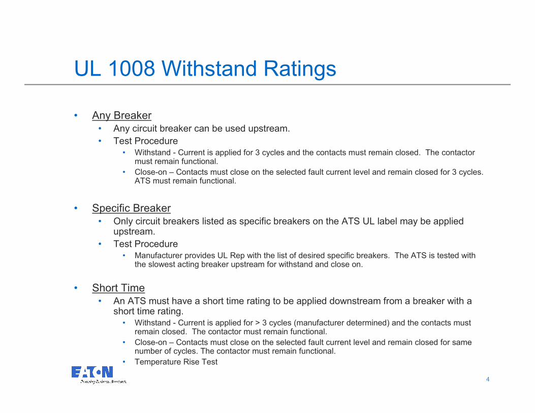
UL 1008 Withstand Ratings
• Any Breaker• Any circuit breaker can be used upstream.
• Test Procedure• Withstand - Current is applied for 3 cycles and the contacts must remain closed. The contactor
must remain functional.
• Close-on – Contacts must close on the selected fault current level and remain closed for 3 cycles. ATS must remain functional.
• Specific Breaker• Only circuit breakers listed as specific breakers on the ATS UL label may be applied
upstream.
• Test Procedure• Manufacturer provides UL Rep with the list of desired specific breakers. The ATS is tested with
the slowest acting breaker upstream for withstand and close on.
• Short Time• An ATS must have a short time rating to be applied downstream from a breaker with a
short time rating.• Withstand - Current is applied for > 3 cycles (manufacturer determined) and the contacts must
remain closed. The contactor must remain functional.
• Close-on – Contacts must close on the selected fault current level and remain closed for same number of cycles. The contactor must remain functional.
• Temperature Rise Test
55
Transfer Switch Equipment and UL1008
In 1997:
UL added 41.20, effective September 18, 1997
41.20 A transfer switch tested for three cycles
shall be marked, When protected by a circuit
breaker without an adjustable short-time
response only or by fuses……
66
Transfer Switch Equipment and UL1008
WHY?
• Unfortunately the UL1008 3-cycle test does NOT
require verification of contact viability. The fact that the
upstream breaker probably trips, and causes an power
failure to the ATS logic, hopefully causes a
subsequent transfer to the backup source.
• If you do NOT verify contact viability in a true short-
time situation you might get caught with an ATS that
acts like a fuse, an upstream breaker that doesn’t trip,
and no power failure to the ATS. Hence a loss of
power to the load!
77
Withstand / Close-on Ratings
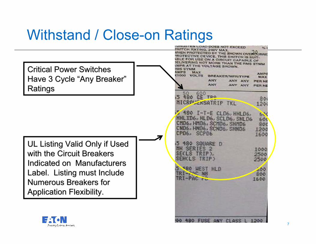
UL Listing Valid Only if Used UL Listing Valid Only if Used
with the Circuit Breakers with the Circuit Breakers
Indicated on Manufacturers Indicated on Manufacturers
Label. Listing must Include Label. Listing must Include
Numerous Breakers for Numerous Breakers for
Application Flexibility.Application Flexibility.
Critical Power Switches Critical Power Switches
Have 3 Cycle Have 3 Cycle ““Any BreakerAny Breaker””
RatingsRatings50 600
88
Specific Breaker Lists
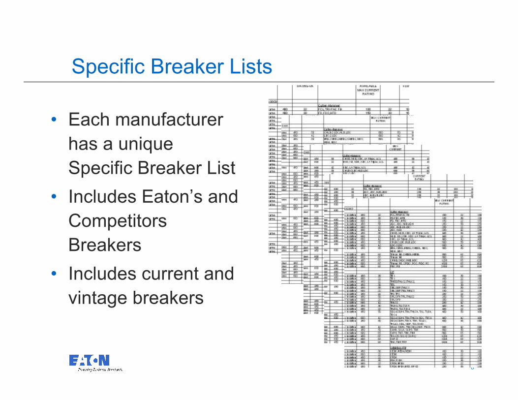
• Each manufacturer
has a unique
Specific Breaker List
• Includes Eaton’s and
Competitors
Breakers
• Includes current and
vintage breakers
99
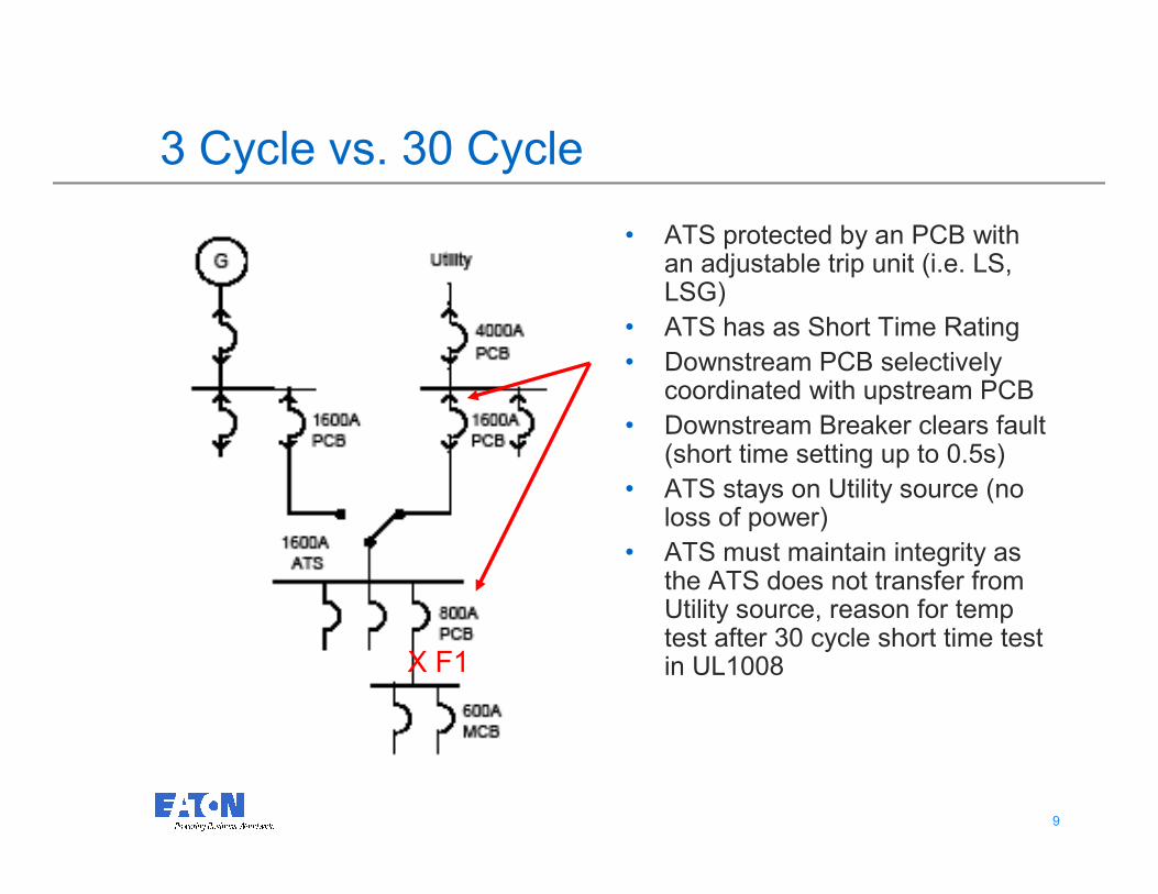
3 Cycle vs. 30 Cycle
• ATS protected by an PCB with an adjustable trip unit (i.e. LS, LSG)
• ATS has as Short Time Rating
• Downstream PCB selectively coordinated with upstream PCB
• Downstream Breaker clears fault (short time setting up to 0.5s)
• ATS stays on Utility source (no loss of power)
• ATS must maintain integrity as the ATS does not transfer from Utility source, reason for temp test after 30 cycle short time test in UL1008X F1
1010
Short Time Definition in UL1008
Short-time current rating is the maximum amount
of fault current a switch can withstand at a
specified voltage for a given amount of time
and remain functional.
1111
Transfer Switch Equipment and UL1008
In 2002 UL added Paragraph 36A Short-Time
Current Rating Test (Optional), and marking
41.20.1.
What is different?
• Paragraph 36A.1 g) requires that a
Temperature Rise test be performed AFTER
the withstand test.
• Paragraph 36A.1 h) requires that the dielectric
withstand test be rerun.
1212
Transfer Switch Equipment and UL1008
If you will be using a breaker with a Short
Time Trip element upstream from the ATS,
then UL indicates you MUST use a
transfer Switch with a UL1008 Short Time
Rating.
1313
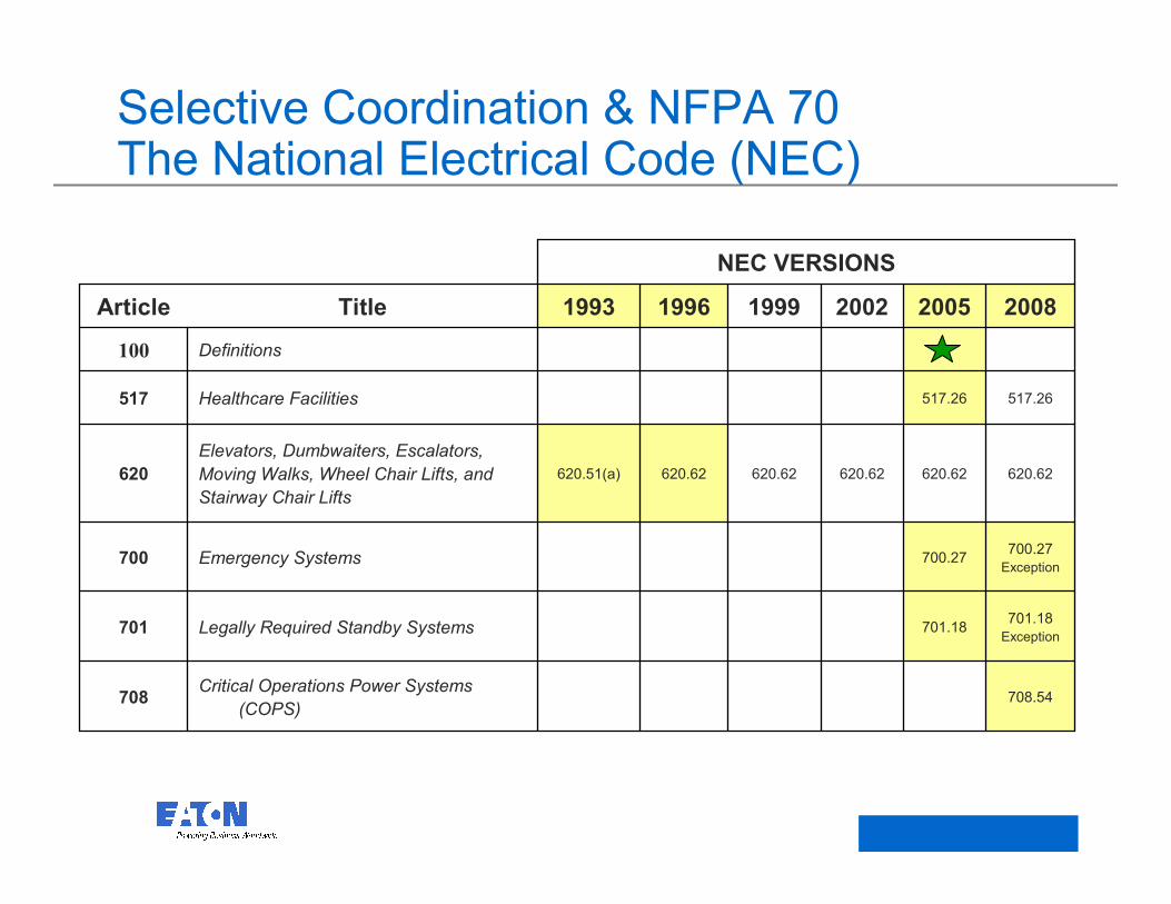
Selective Coordination & NFPA 70 The National Electrical Code (NEC)
708.54Critical Operations Power Systems
(COPS)708
701.18
Exception701.18Legally Required Standby Systems701
700.27
Exception700.27Emergency Systems700
620.62620.62620.62620.62620.62620.51(a)
Elevators, Dumbwaiters, Escalators,
Moving Walks, Wheel Chair Lifts, and
Stairway Chair Lifts
620
517.26517.26Healthcare Facilities517
Definitions100
200820052002199919961993TitleArticle
NEC VERSIONS
1414
Conclusion on Short Time Ratings
• Although the Short time test is optional, it is
required for certain applications.
• If your ATS is not labeled with a short time
rating as shown, it is a misapplication of the
ATS if selectively coordinated between
breakers set higher than 3 cycles.
• A 3 cycle ATS rating can only be protected by
a breaker with an instantaneous trip.

© 2008 Eaton Corporation. All rights reserved.
This is a photographic template – your
photograph should fit precisely within this rectangle.
Switching the Neutral
1616
When to Switch the Neutral
• It is recommended to switch the neutral when working
with a separately derived system. This is generally
accomplished with a fully rated four pole switch or by
utilizing a three pole switch with an overlapping
neutral.
• Non-Separately Derived System - Those systems where only
one bonding jumper between the neutral and ground exists.
• Separately Derived System – Each power source has it’s own
reference to ground.
1717
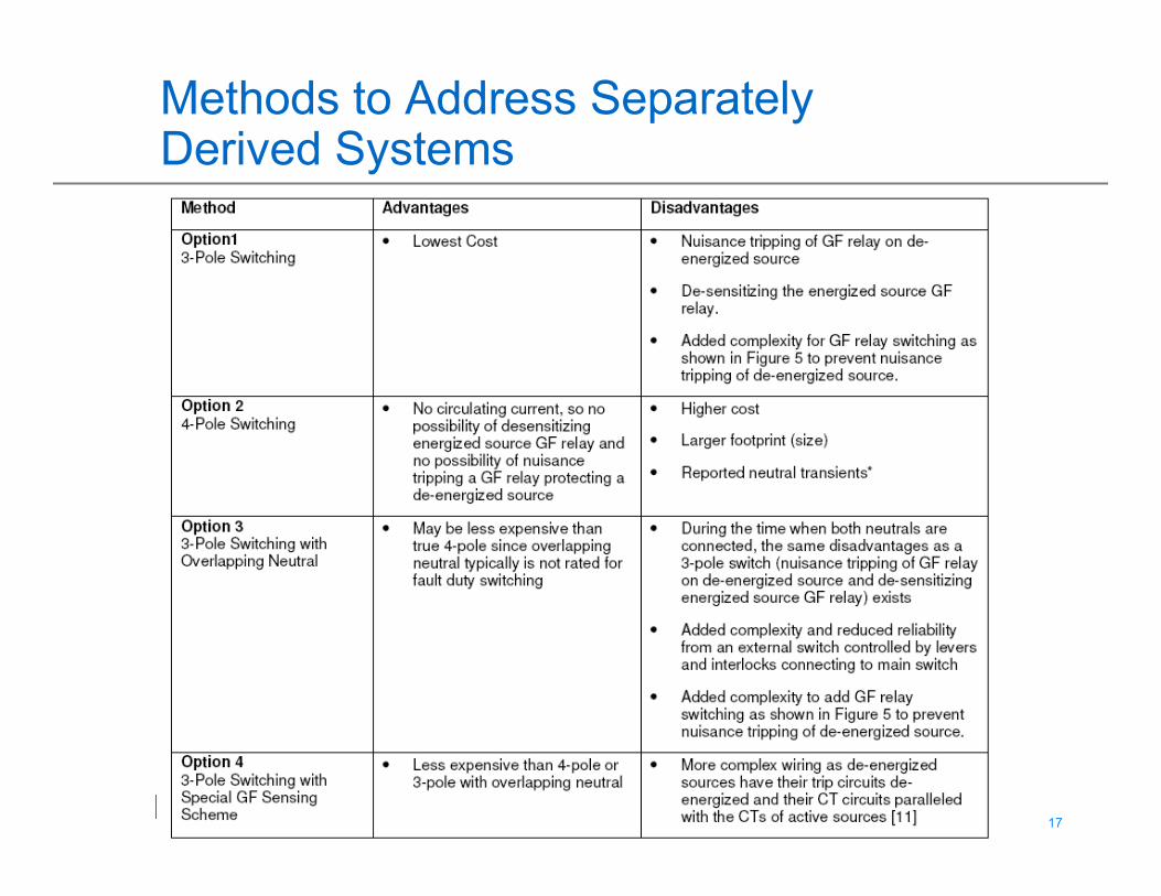
Methods to Address Separately Derived Systems
1818
Reference White Paper – 3 pole vs. 4 pole switching
http://www.eaton.com/ecm/idcplg?IdcService=G
ET_FILE&dID=223905

© 2008 Eaton Corporation. All rights reserved.
This is a photographic template – your
photograph should fit precisely within this rectangle.
New Bypass Isolation Transfer Switch Technology
2020
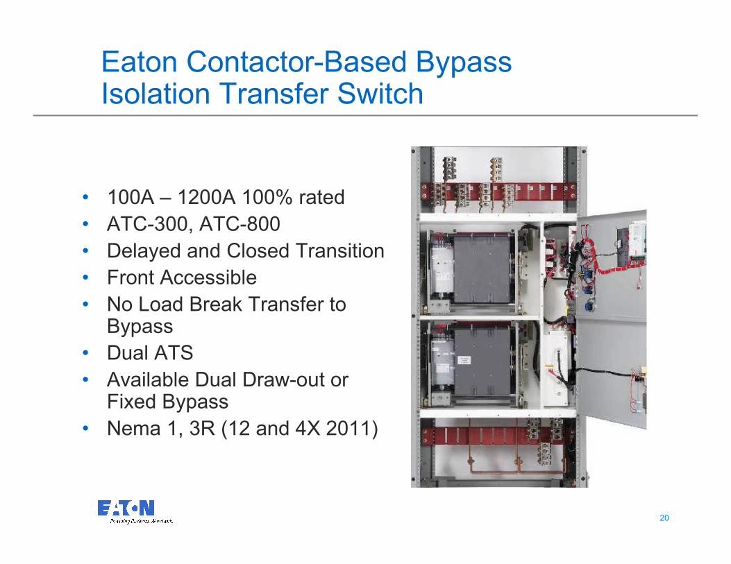
Eaton Contactor-Based Bypass Isolation Transfer Switch
• 100A – 1200A 100% rated
• ATC-300, ATC-800
• Delayed and Closed Transition
• Front Accessible
• No Load Break Transfer to Bypass
• Dual ATS
• Available Dual Draw-out or Fixed Bypass
• Nema 1, 3R (12 and 4X 2011)
2121
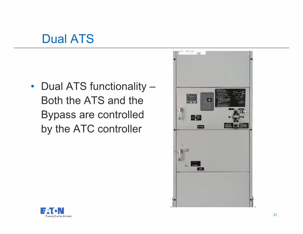
Dual ATS
• Dual ATS functionality –
Both the ATS and the
Bypass are controlled
by the ATC controller
2222
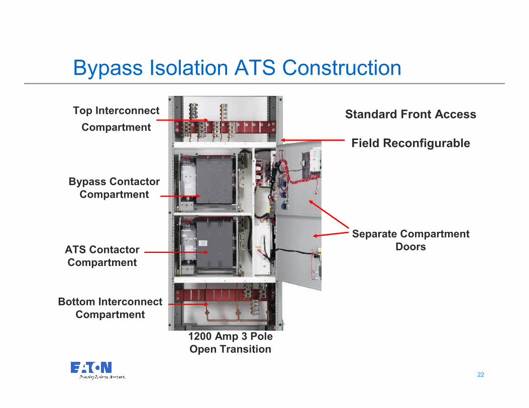
Bypass Isolation ATS Construction
Top Interconnect
Compartment
Bottom Interconnect
Compartment
Standard Front Access
Field Reconfigurable
Separate Compartment
DoorsATS Contactor
Compartment
Bypass Contactor
Compartment
1200 Amp 3 Pole
Open Transition
2323
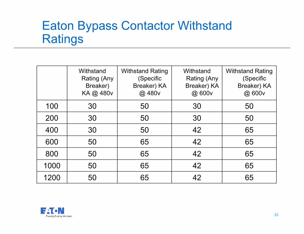
Eaton Bypass Contactor Withstand Ratings
654265501200
654265501000
65426550800
65426550600
65425030400
50305030200
50305030100
Withstand Rating
(Specific
Breaker) KA
@ 600v
Withstand
Rating (Any
Breaker) KA
@ 600v
Withstand Rating
(Specific
Breaker) KA
@ 480v
Withstand
Rating (Any
Breaker)
KA @ 480v
2424
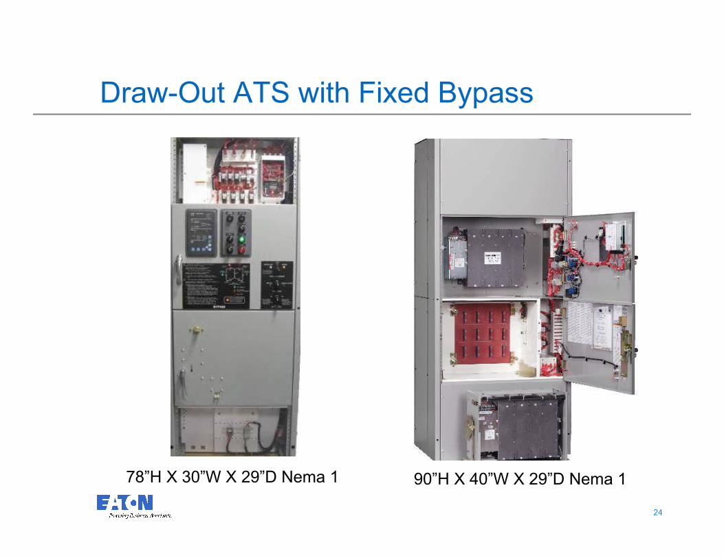
Draw-Out ATS with Fixed Bypass
90”H X 40”W X 29”D Nema 1 78”H X 30”W X 29”D Nema 1
2525
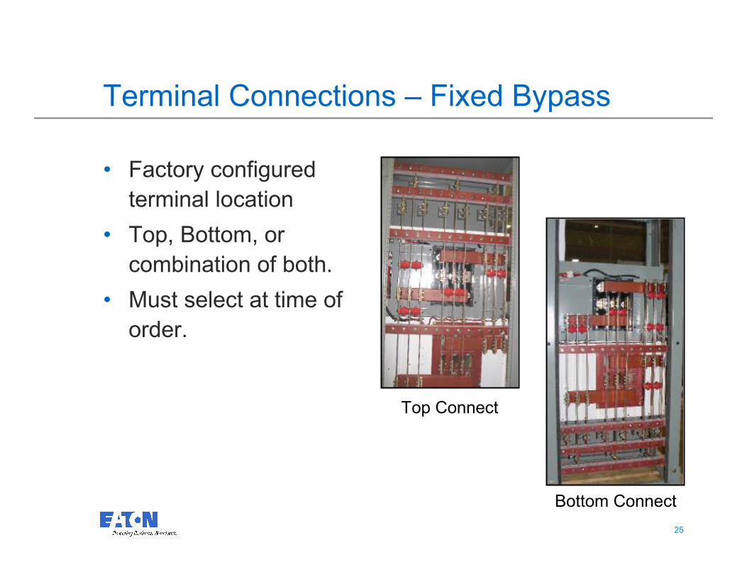
Terminal Connections – Fixed Bypass
• Factory configured
terminal location
• Top, Bottom, or
combination of both.
• Must select at time of
order.
Top Connect
Bottom Connect

2626
Dual Draw-out (Optional)
• ATS and Bypass contactors are
identical, thus interchangeable
• Both the ATS and Bypass are
draw-out contactors
• Connection to Contactor
• Locked In Position –
Connected
• Isolated Position –
Connected
• Racked Out – Disconnected
90”H X 40”W X 29”D Nema 1
Bypass
ATS
2727
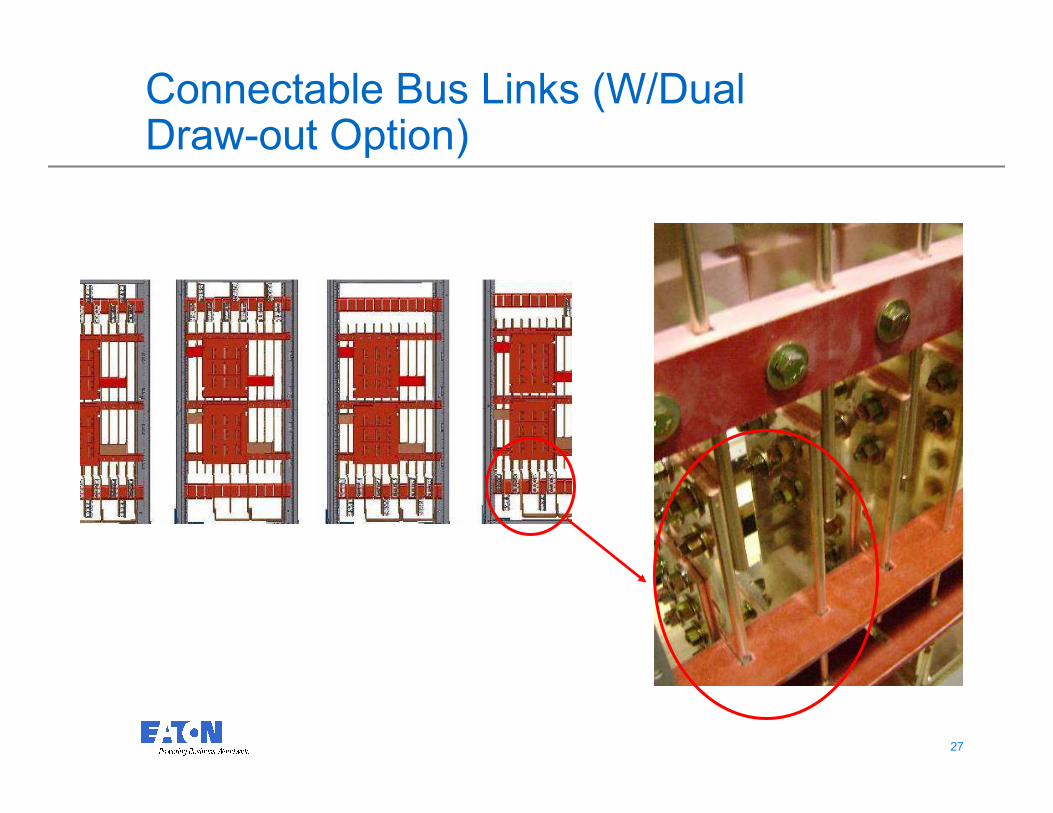
Connectable Bus Links (W/Dual Draw-out Option)
2828
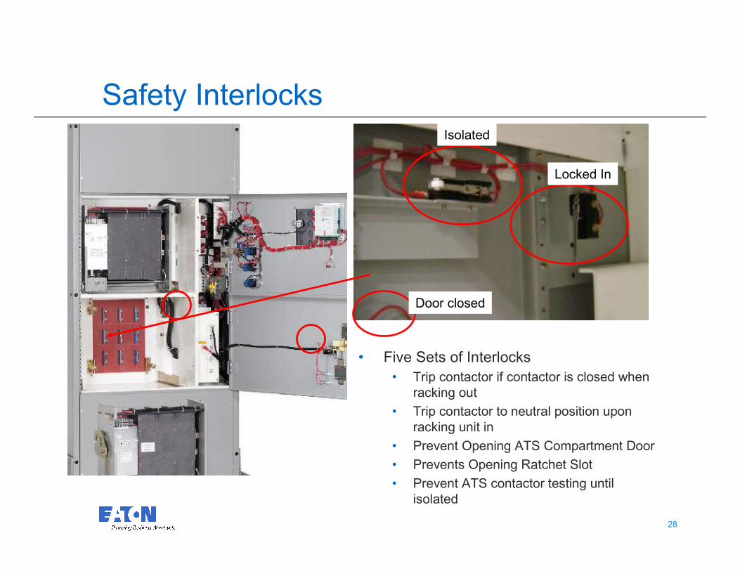
Safety Interlocks
• Five Sets of Interlocks
• Trip contactor if contactor is closed when
racking out
• Trip contactor to neutral position upon
racking unit in
• Prevent Opening ATS Compartment Door
• Prevents Opening Ratchet Slot
• Prevent ATS contactor testing until
isolated
Locked In
Isolated
Door closed
2929
Questions?