trajectory optimization for an …...trajectory optimization and guidance for an aerospace plane...
TRANSCRIPT

TRAJECTORY OPTIMIZATION AND GUIDANCEFOR AN AEROSPACE PLANE
/p3/J:__>7
Final Report / p - o5- C/:2...September 1988 through August 1989
September 1989
Research Supported by NASA Langley Research Center
NASA Grant Number NAGI-907
Principal Investigator: Kenneth D. MeaseGraduate Research Assistant: Mark A. Van Buren
Department of Mechanical and Aerospace EngineeringSchool of Engineering and Applied Science
Princeton University, Princeton, New Jersey 08544
NASA Grant Monitor: D. D. Moerder
(NASA-CR-185884) TRAJECTORY OPTIMIZATION
AND GIJlDANCE FOR AN AFROSPACE PLANE Final
Report, Sept. 198B - Aug. 1989 (PrincetonUniv.) 42 p CSCL OIC
G3/o5
N90-13369
Unclas
0231728
\\
https://ntrs.nasa.gov/search.jsp?R=19900004053 2020-06-16T19:02:32+00:00Z

TABLE OF CONTENTS
ACKNOWLEDGEMENTS .................................................................. 2NOTATION .................................................................................... 3SUMMARY OF WORK COMPLETED ................................................. 41. INTRODUCTION ........................................................................ 52. PROBLEM FORMULATION .......................................................... 6
2.1 Equations of Motion .......................................................... 62.2 Initial and Final Conditions .................................................. 72.3 Performance Index ............................................................. 82.4 State and Control Constraints ............................................... 8
2.5 Optimality Conditions ......................................................... 83. VEHICLE MODELING ................................................................. 12
3.1 The Aerodynamic Characteristics ............................................ 123.2 The Propulsion System ....................................................... 12
3.1.1 The Ramjet .......................................................... 133.1.2 The Scramjet ........................................................ 133.2.3 The Rocket .......................................................... 14
4. SOLUTION APPROACH ............................................................... 155. RESULTS .................................................................................. 16
5.1 Effect of Acceleration Constraints .......................................... 165.2 Effect of Available Thrust Level ........................................... 17
5.3 Effect of Fuel Specific Impulse ............................................ 176. CONCLUSIONS AND WORK IN PROGRESS .................................. 18REFERENCES ................................................................................ 19TABLES ........................................................................................ 21FIGURES ...................................................................................... 23APPENDIX .................................................................................... 33
A.0 INTRODUCTION ............................................................. 33A. 1 AMBIENT AND FREE-STREAM CONDITIONS ...................... 33A.2 THE AFTERBURNING TURBOJET ..................................... 33
A.2.1 The Intake ........................................................... 34
A.2.2 The Compressor .................................................... 34A.2.3 The Combustion Chamber ....................................... 35
A.2.4 The Turbine ......................................................... 35A.2.5 The Afterburner .................................................... 36A.2.6 The Nozzle .......................................................... 36
A.3 THE RAMJET ................................................................. 37A.4 THE SCRAMJET ............................................................. 38
A.4.1 The Intake ........................................................... 38A.4.2 The Combustion Chamber ....................................... 38A.4.3 The Nozzle .......................................................... 39
A.5 CONCLUSION ................................................................ 40

ACKNOWLEDGEMENTS
The authors thank the United States Air Force for allowing us to use the OTIS computer
program.

3
Aa
C
CD
CL
Cv
ERfG
gHh
LM
m
PpxQ
qRr
STt
VWW
X
Y110
izK
Subscripts
a
c
KERt
0
NOTATION
Cross Section AreaAcceleration
State and Control Inequality ConstraintDrag CoefficientLift Coefficient
Velocity CoefficientConstant Pressure Specific HeatDrag ForceExpansion RatioFuel to Air RatioAcceleration Load LimitGravitational Acceleration
Heating Value, HamiltonianAltitude
Fuel Specific ImpulseProcess EfficiencyLift ForceMach Number
Mass, Mass FlowPressure
Adjoint Variable to the State XHeating RateDynamic PressureEarth Equatorial Radius, Gas Constant AirRadial Distance to the Center of the Earth, Nose Radius
Surface Area, State Inequality ConstraintThrust, Absolute TemperatureTime
VelocityWeightJet VelocityDown Range
Angle-of-Attack
Direction Angle of the Resultant Aerodynamic Force, tanl3 = L/D
Flight-Path-Angle, Ratio of Specific Heats
Efficiency
Thrust Pitch Angle
Gravitational Constant, Lagrange MultiplierLinear Throttle
AmbientCombustor
Kinetic EnergyPressure Recovery
Stagnation ConditionStandard, Entry

4
_: f
SUMMARY OF WORK COMPLETED
The first step in our approach to developing guidance laws for a horizontal take-off,air-breathing single-stage-to-orbit vehicle is to characterize the minimum-fuel ascenttrajectories. We have developed the capability to generate constrained, minimum-fuel ascenttrajectories for a single-stage-to-orbit vehicle. A key component of this capability is the generalpurpose trajectory optimization program OTIS, developed by the Boeing Company for the AirForce. The pre-production version, OTIS 0.96, has-b_en installed and run on a Convex C-1at Princeton University. A more recent version, OTIS 1.2, is to be installed in September1989. We have developed supporting software for generating initial guesses. By employing adirect solution method, state inequality constraints, inherent features of the ascent problem, canbe routinely handled without resorting to reduced-order approximations for the vehicle point-
mass dynamics.A propulsion model has been developed covering the entire flight envelope of a
single-stage-to-orbit vehicle. Three separate propulsion modes, corresponding to anafter-burning turbojet, a ramjet and a scramjet, are used in the air-breathing propulsion phase.For each mode, propulsion performance is modeled using a simple one-dimensional flowanalysis. By varying the propulsion model parameters over a reasonable range, one obtains afamily of propulsion systems exhibiting certain salient propulsion characteristics covering therange of anticipated propulsion system behavior. A variable thrust rocket engine isimplemented for orbit insertion and flight in the upper regions of the atmosphere.
The GHAME aerodynamic model of a hypersonic air-breathing single-stage-to-orbit vehiclehas been ob_ined and implemented. Note that, though the present aerodynamic and propulsionmodels provide a reasonable s!aning point for our investigations, other models can be readily
implemented._ Preliminary results pertaining to the effects of variations in acceleration constraints,
available thrust level and fuel specific impulse on the shape of the minimum-fuel ascenttrajectories have'been obtained. The results show that, if the air-breathing engines are sized foracceleration to orbital velocity, it is the acceleration constraint rather than the dynamic pressureconstraint that is active during ascent. Realistic acceleration constraints can be accommodatedby proper adjustment of the throttle and angle of attack with only minor mass penalties. Theacceleration constraint is accommodated by increasing the angle of attack to raise the flight pathduring potentially high acceleration periods and throttling back when the acceleration limit isreached. There are finite trajectory segments on the acceleration boundary. The response to
decreasing the level of available thrust is that the vehicle flies uniformly at lower altitude. Theflight time is increased, as is the fuel consumption. Changing the Isp has little effect on theoptimal trajectory and controls, but does increase the fuel consumption as expected.
!
5
1. INTRODUCTION
Horizontal take-off, single-stage vehicles, using air-breathing as well as rocket propulsion,
may offer a more economical means of transporting payloads to orbit. The anticipatedadvantages are the operational flexibility of horizontal take-off, the operational simplicity.of asingle-stage, and the propellant mass reduction that results from using air-breathing engines.The ultimate objective is to rely completely on the air-breathing engines to accelerate to orbitalspeed. Effective use of air-breathing propulsion over the entire supersonic and hypersonicspeed range requires a ramjet with both a subsonic-combustion mode and asupersonic-combustion mode. To accelerate during the subsonic and transonic phases someadditional propulsion mode(s) is necessary. Further discussion of the propulsion systemdevelopment can be found in [1]. The effective use of air-breathing engines leads to loweraltitude ascent trajectories as compared to those of the Space Shuttles. Higher dynamicpressure, higher surface temperatures, and higher acceleration loads result.
A number of studies have been conducted to determine the performance potential of anair-breathing SSTO vehicle. The study by Schoettle [2] provides useful background for ourwork. Schoettle compared rocket versus combined rocket and ramjet/scramjet performance andconcluded that the use of a ramjet engine(s) allows substantial propellant savings, but is heavilypenalized by the added weight of the ramjet engine and the structural reinforcements required toaccommodate the higher dynamic pressures. The maximum payload delivery trajectoryinvolved dynamic pressures of up to 5850 psf. Only by accommodating dynamic pressures upto at least 1044 psf could a payload delivery advantage over a rocket driven vehicle be realized.As a point of reference, the Space Shuttles do not experience dynamic pressures above 650 psfduring their ascent. The payload mass versus peak dynamic pressure curve had a steep slopeup to 1566 psf, at which point the payload mass was 80% of the maximum achievable value.Between 1566 psf and 5850 psf, the slope was small and relatively constant. The results ofthis study by Schoettle and other similar studies offer incentive for continuing research towardsthe development of an air-breathing SSTO vehicle.
Our objective is to develop guidance logic for a horizontal take-off, air-breathing SSTOvehicle. As a first step, we aim to characterize the minimum-fuel trajectories that an air-breathing SSTO vehicle should ideally fly to achieve maximum performance. Because the
optimal trajectory characteristics are critically dependent on the propulsion system andaerodynamic models one adopts, and because there is significant uncertamty as to what thesemodels should be, we will parameterize our ignorance as much as possible, so as to explore therange of possibilities and determine the sensitiVities to various features of the models. We will
also explore the effects of dynamic pressure, heating, and acceleration constraints on thecharacter of the optimal trajectories. Our guidance approach will then follow naturally from anunderstanding of the ideal optimal trajectories and controls. That is, the characteristics andappropriate approximations on which to base the guidance scheme will be inferred from theresults.
In this report, we lay the groundwork for our characterization of minimum-fueltrajectories for an air-breathing SSTO vehicle. The problem formulation is given. Thepropulsion system and aerodynamic models are discussed. The solution approach is outlined.And some preliminary results are presented.

' 6
2. PROBLEM FORMULATION
In all its generality, the determination of an ascent trajectory, let alone an optimal one, forany launch vehicle constitutes an elaborate problem in itself. With the added complexity ofsustained flight in the atmosphere for an extended period of time, inherent to an air-breathingSSTO vehicle, the problem becomes even more formidable. The purpose of this researchhowever, is to obtain a characterization of minimum-fuel ascent trajectories. The optimal
trajectory characteristics will provide the basis for the subsequent development of a guidancescheme. Therefore, the introduction of some simplifying assumptions which would reduce the
overall complexity of the ascent problem without significantly affecting its character is justified.First, the Earth is assumed to be modeled as a homogeneous sphere. Neglecting the
oblateness and inhomogeneity of the Earth implies a central gravity field and allows us to use
the simple inverse square law (g = IMr2) for the gravitational acceleration.Second, the Earth is assumed to be non-rotating. This simplification is acceptable
considering the very small accelerations experienced due to the Coriolis force. Furthermore, ifthis force was included the orientation of the ascent trajectory with respect to the Earthrotational axis would come into play, complicating a general trajectory characterization.
Third, the atmosphere is taken to be stationary and in what follows the use of a standardatmosphere providing ambient conditions as a function of altitude only has been assumed.
2.1 Equations of Motion
At this stage we are not considering ascent from a specific launch site to a specific targetorbit, but the simpler problem of ascending to a generic low Earth orbit. Intuitively, theminimum-fuel ascent trajectory for this case will not exhibit out-of-plane motion, that is, the
ascent trajectory will be confined to a great circle plane and the heading is fixed. Imposing thisrestriction a priori eliminates the bank angle as a control variable, simplifying the controlproblem even further. Subsequent work dealing with specific launch site-target orbit pairingswill need to take out-of-plane motion into consideration. With this additional simplification andthe usual no-slip condition, the dynamic equations describing the motion of the vehicle (or
more precise the motion of the center of mass of the vehicle) are [3,4]
dV T cos(0 + 0t) - D
dt - m - g sin_' (1)
d_' L +T sin(O+ oO (V g)dt - mV + V cos _' (2)
dr
d-t- =V sin _' (3)
dX=vRdt T cos y (4)
dm TR m
dt g 01 sp (5)
where R is the radius of the Earth and go = P-/R2. Observe that the direction of the thrust is
fixed with respect to the body axes and lies in the vehicle's plane of symmetry. The line of

7
thrustis offsetwith a fixed thrustpitchangle0 with respectto the line of zeroangle-of-attack.Theaerodynamicforcesaredescribedby
L = CLq Sref D = CD q Sref (6)
where the lift coefficient (CL) and the drag coefficient (CD) are functions of the angle-of-attack
(o0 and Mach number (M), q is the dynamic pressure and Sref is a reference area. Thepropulsive force is given most generally by
T = '_z_,x kTmax (M, pa, Ta, o0k k (7a)
or, equivalently in a standard atmosphere (e.g. the U.S. Standard Atmosphere, 1976 [5])where the ambient pressure and temperature are functions of the altitude (h = r - R) only, by
T=X xk Tmax (M,h, o0k k (7b)
where Xk is a continuous linear throttle factor ranging from zero to one. The thrust dependence
on ct reflects the influence of incidence on the engine intake performance. The index k allows
for more than one particular propulsion mode to be effective at the same time: for example, theuse of a throttleable rocket along with a scramjet in the higher regions of the atmosphere.
Likewise, the specific impulse (Iso) is a function of Mach number and either the ambientconditions or the altitude in a standard _tmosphere
Isp =Isp (M, Pa, Ta,_) Isp =Isp (M,h, o0k k k k (8)
The common assumption is made here that the value of the Isp is not affected by throttling of
the engine. This assumption is not always justified and the- Isp can depend in a nonlinearfashion on the throttle setting. However, determining Iso as a function of the linear throttleinvolves the non-trivial inversion of the propulsion modeland seems unwarranted at this stage.
The vehicle dynamics are thus controlled by the angle-of-attack tx and the set of linear
throttles Xk.
2.2 Initial and Final Conditions
Ideally one would like to consider the ascent from release of the brakes at the beginning ofthe runway, to insertion into low Earth orbit (LEO). In practice however the execution of aminimum fuel ascent will be restricted by safety and operational considerations to commenceafter take-off and initial-climb out. Additionally, the acceleration to supersonic speeds
employing a turbojet-like mode of propulsion is well understood and this phase of the ascent toorbit accounts for only a small portion of the total fuel consumption. Hence our work has been
focused on the high-speed phase of the ascent.Similarly, the final insertion into low Earth orbit using a rocket orbital maneuvering system
is well understood and actual determination of the orbit insertion might be computationallyintensive due to extreme sensitivity of various orbital parameters to the insertion parameters.Instead, acceleration to circular speed at the edge of the sensible atmosphere is used to
benchmark the various optimal ascent trajectories.

8
Subsequentworkmayincludeamoredetailedlook atthecouplingbetweenthetrunkascenttrajectoryandtheinitial climb-outandorbitalinsertionphaserespectively.
2.3 Performance Index
Since this work is concerned with minimum-fuel ascent to orbit the obvious performance
index to be minimized is the fuel expenditure. For a vehicle with a fixed gross take-off weightthis is equivalent to maximizing final weight. The ultimate purpose of the air-breathing ascent is
to maximize payload/fuel mass fraction. To this end one should make the gross take-off weighta design (i.e. free) variable. This has not been taken up here since, if done properly, it wouldamount to a full-fledged design study. Our study is limited to the case of a fixed gross take-offweight and the minimum-fuel ascent trajectories are obtained by formally maximizing the finalmass.
2.4 State and Control Constraints
Vehicle and crew considerations dictate certain constraints that must be placed on the states
and/or controls. The throttle settings must take on values between 0 and 1. The angle of attackmust take on values between O_rninand Otmax. The value of Otmax corresponds to either the stall
boundary or a propulsion system dictated boundary. The minimum angle of attack is dictated
by the propulsion system characteristics or the limits of our aerodynamic data. _min is typically
some small negative angle.We consider two state and control inequality constraints that place limits on the axial and
normal acceleration loads
C1=1 1/m(rtTmax- (L 2 + D2)1/2 cos( 0t + 13))1 - Gaxial < 0 O)
C2 = I 1/m ((L 2 + D2) 1/2 sin(or + 13)) I - Gnormal < 0 (10)
where tan13 = L/D and Gaxial and Gnormal are the imposed acceleration limits. A less specificoption for constraining the acceleration load is to limit the total acceleration load
C = 1/m (Tz2Tmax 2 + L 2 + D 2 + 2uTmax(Lsino_ - Dcosot))1/2 . Gtotal < 0
We also consider the two first-order state inequality constraints that place limits on the
heating rate and dynamic pressure
S1 = K p 1/2 V 3 - Qmax < 0 (11)
1 pl/2 V2 < 0 (12)52 = _ - qmax -
Clearly, the set of constraints could be greatly expanded, but this would require specificvehicle knowledge. In order to keep our study generic and not over-complicate thecomputations, we will not go beyond the above set of constraints.
2.5 Optimality Conditions
Even though we will be employing a direct method of solution, some insight into thecharacteristics of the minimum-fuel trajectories and controls may be obtained from deriving the
optimality conditions that would form the basis of an indirect method of solution.

9
TheHamiltonianfor theconstrainedminimum-fuelascentproblemis
H=pr'V+pv" (T + A) + g(r) -Pmg-_sp+.= I.tiCi
wheregi, i = 1-4,areLagrangemultipliers
l_i _< 0 for Ci = 0
I.ti = 0 for Ci < 0
and
dS1C3- dt
dS2C4 = dt
The equations for the adjoint variables are
(13)
dpr 0H (14)dt - - 0r
dpv OH (15)dt - 0V
0H (16)dt - - 0m
If the optimal trajectory contains an arc that is on the boundary of one of the first-order stateconstraints, conditions of the form [6]
Si(r,V) = 0 (17)
- 0Si .prT(tk -) = prT(tk +) + Xr-_r' tk) (18)
- 0Si .pvT(tk ") = pvT(tk +) + _.v _--_-(tk) (19)
pm(tk-) = pm(tk +) (20)
H (tk-) = H(tk +) (21)
apply at the entry or exit from the boundary arc, where tk is the entry or exit time and Xr and
_.v are scalar Lagrange multipliers. The entry and exit points may or may not be comers, i.e.,places where some or all of the controls are discontinuous.
For flight away from the constraint boundaries, the optimal controls are as follows. Basedon the Maximum Principle, the values of the controls at each point along the optimal trajectory

10
should maximize H. Taking the partial derivativesof H with respectto the controls andexpressingthe result in terms of the statevariables usedin Eqs. (1)-(3) and(5) and thecorrespondingadjointvariables,weobtain
Tm_lm__(p sin(0+ at) mp) (22)allan_ v cos(0 + at)+ p_, V Pm gsTs
COS(O + at) + qS OCL_ (TmV --_-)- Pv sin(O+ at) + q_SaCD
m a_ 2
(23)
Since the control n appears linearly in H and OH/0x is its coefficient, H is maximized by
choosing n according to the rule
n = 0 if OH/0n<0
x = 1 if OH/0x>0
(24)
If OH/0n = 0 over a finite interval of time, the control is singular and must be determined
from higher order conditions. We will show below that the singular case can be ruled out. The
control at is bounded from above and below. H may be maximized by atmin, O_max, or an
interior value of at that satisfies the implicit equation
T sin(O + u) + q S OCD_p_z_ _ m m Oa
Vpv - T cos(0 + + a__cLm m 0at
(25)
The Hessian of H with respect to the controls, denoted by Huu, has components
(26)
02H a2H Tmax (_ Pv sin(0 + o_) + PVa- n = naat - m coS(0v + a)) (27)
a2H xTmax Pv cos(0 + at) + _V sin(0 + at) +qS a2CL- Pvact2 - m m ao_2 aot2 )
(28)
If an interior value of at satisfying Eq. (25) maximizes H, the second partial given in
Eq. (28) should be less than or equal to zero; if it is equal to zero, higher derivatives with
respect to at would have to be checked.In order to determine whether a singular thrust arc can be optimal, we examine the
determinant of Huu. From Eqs. (26)-(28), it follows that

11
det(Huu) = - - pv sin(0 + oc)+ p_ V (29)
Thusdet(Huu)< 0. If det(Huu) < 0, Huu is indefinite and the singular arc is not optimal. Ifdet(Huu) = 0, then the singular arc may be optimal and additional conditions would have to bechecked. The first factor on the right-hand-side of Eq. (29) is never zero based on physical
reasoning; the second factor is zero only if Pv = l:h' = 0 or
tanot 2-I- (30)= Vpv
The first condition implies that Pr = Pm = 0 as well and is inconsistent with an optimalsolution. Referring to Eq. (25), the second condition can only be satisfied in the limit as thedensity p (and hence q) goes to zero, i.e., outside the atmosphere. Consequently, we concludethat singular thrust arcs are not optimal during the ascent through the atmosphere. Corban,Calise, and Flandro[28] reached the same solution for a reduced-order model of the point mass
dynamics.Transversality conditions, integrals of the motion, and the optimal controls for flight on the
constraint boundaries will not be developed here, since no further insight is expected. We onlyremark that intermediate values of throttle are possible along constraint boundaries. The resultsto be described later show that indeed intermediate values of throttle are used to fly along the
boundary of the acceleration constraint.In the above development, the issue of choosing the optimal propulsion mode has not been
addressed. Accounting for the existence of different propulsion modes, we rewrite theHamiltonian as
k
i__ l c°s( 0Hreduced = m + _ sin(0 + 0_) Pm "_mV - g0(Isp)i) _i(Tmax)i
[ Pv
k
P_, Pm] 1_1=
rcos(0 + a)hm
sin(0 + 0t)m
1
_, gO(Isp)i .j
/q(Tmax)i (31)
where k is the number of propulsion modes and the subscript "reduced" denotes that the termsnot involved in determining the optimal throttle setting have been suppressed. In the secondline of the equation, the reduced Hamiltonian is expressed in the form of an inner product(actually there are k inner products). At this point in our investigations, we are assuming that
only one propulsion mode is active at any given time. The optimal mode is the one associatedwith the largest of the k inner products. Since the angle of attack appears in these inner
products and the k throttle settings appear in the equations for determining the optimal angle ofattack, the optimal controls must be determined by simultaneous maximization of theHamiltonian. At points along the optimal trajectory where there is a switch from one propulsionmode to another, there will in general be comers where there are discontinuities in the time
derivatives of the speed and flight path angle.
12
3. VEHICLE MODELING
The current vehicle configuration is conform a series of NASA reports on a HypersonicResearch Airplane Concept [7-10]. The airframe is expected to be a cross between a flying
body and a delta wing with a belly-mounted multi-mode engine. The gross take-off weight ofthe SSTO vehicle is estimated to be 300,000 lbf of which approximately 60 % is fuel [11]. Theoverall length of the vehicle is approximately 233.4 ft and its aerodynamic reference area is
6,000 sqft.Liquid hydrogen is used as fuel over the entire speed range since it allows for the high
effective specific impulse that makes air-breathing propulsion a viable option and is suitable forsupersonic combustion. Recently, slush hydrogen has been mentioned as an operationallymore attractive form of the hydrogen fuel [12].
3.1 The Aerodynamic Characteristics
Currently, there is a dearth of up-to-date aerodynamic data concerning lifting vehiclesflying at hypersonic speeds. However, representative values for the lift and drag coefficientscovering the entire flight regime of a SSTO vehicle, have been obtained from. The generichypersonic aerodynamic data therefore contains certain realistic aerodynamic anomalies.
The present study is concerned with guidance for performance, that is, it considers themotion of the vehicle's center of mass. The CL and CD values used in this point mass model
are the trimmed (equilibrium) values as functions of Mach number and angle-of-attack o_; therotational dynamics are not accounted for.ones obtained by instantaneous trimming of thevehicle. We currently employ the trim map found in the Generic Hypersonic AerodynamicModel Example (GHAME) [11] which covers the entire flight regime of a SSTO vehicle. Thismodel is an amalgamation of the characteristics of the space shuttles, the X-24C lifting bodyand a 70 ° swept double delta wing configuration. In Figure 1, CL and CD are plotted as afunctions of Mach number for a selected number of angles-of-attack. These plots are obtained
from the original data grid by quadratic interpolation over 0t for fixed Mach number andsubsequent determination of cubic splines for the quadratic coefficients over the Mach numberrange. Actual numerical calculations however employ local 2-dimensional quintic interpolation
applied to the original data grid.
3.2 The Propulsion System
The aero-engine for an air-breathing SSTO vehicle comprises several distinct propulsionmodes, each suited to operate over a specific speed range. Our present propulsion modelconsists of an afterburning single-flow turbojet, a ramjet and a scramjet. The model is
designed to provide maximum specific thrust and the corresponding fuel specific impulse. Therespective modes are analyzed using simple one-dimensional flow analysis for perfect gases,employing appropriately con stant efficiencies [ 13 -18].
A simple turbojet model has been developed for completeness and may or may notaccurately represent the actual low speed propulsion mode; there is still much uncertainty aboutthe kind of propulsive device to be used for take-off and climb-out.
The emphasis of our work has been on the high-sp.eed phase of the ascent after initialacceleration to supersonic speeds. At these speeds a ramjet with either subsonic or supersoniccombustion is most suitable. Though we do not want to concern ourselves with the mechanicalparticulars of such an engine, one may visualize an integrated device where upstream transferof the combustion process effects a switch from a ramjet with conventional subsoniccombustion to a ramjet with supersonic combustion: a scramjet. A brief description of therespective ramjet propulsion modes is presented in what follows, for more detail the reader isreferred to the Appendix.

13
The advantageof the presentpropulsionmodel basedon fundamentalthermodynamicrelationsis thatit allowsusto obtaindifferentpropulsioncharacteristicsby changingspecificengineefficienciesandparameters.
At high speedstheentirevehiclebecomesa flying engine,its forebodyfunctioning asacompression surface and its trailing edge as an expansionsurface. The inlet and exitcharacteristicsof thepropulsiondevicecanthereforenotbemodeledaccuratelyby asimplifiedanalysisor existingdesignmethods(e.g.additivedrag,intakeefficiency andnozzlelosses).However,it is reasonableto expectthat thevariablegeometryinlet is designedto reducetheeffectof inlet spillageon theperformanceandthattheintakeis alwaysmatchedto theengine.Hence, for the moment, additive drag has beenneglected.Similarly, the 3D-nozzle isrepresentedonly by its thermodynamicworkings.A simpleestimatefor theinternalfriction oftheenginehasbeenincorporated.
The effect of incidenceon the engineperformancewith belly-mountedenginepodsistwofold [19]. First, increasedincidenceleadsto a larger masscaptureby forebody-intakesystemand thuswill enhancethethrust.On theotherhand increasedincidenceproducesastrongerbow shockandwill decreasetheefficiency of the intakeprocessthusdecreasingthethrust.At very high incidencethelossin efficiency will outweighthegain in massflowsincethelatterhasanupperbounddictatedby theenginesize.Thetwooppositetrendswill thereforemost likely result in eitheran immediateroll-off in thrustor an initial increasefollowed by aroll-off.
3.1.1The Ramjet. The airflow is diffusedadiabaticallyto subsonicspeedswith constantkinetic efficiency. The airflow entersthecombustorat constantMach number.Combustiontakesplace with constantburning efficiency and a fixed drop in stagnationpressure.Theamountof fuel isdeterminedbythemaximumcombustorexit temperature.
Next the airflow is acceleratedagain to supersonicspeedsthrough a continuouslyadjustableconvergent-divergentnozzle.Ideally theflow shouldexpandto ambientpressureformaximumperformance,however,thenozzle'sexpansionratio is limited by themaximumsizeof theexit area.
The specific thrust and specific impulsedeterminedfrom this model for a couple ofaltitudesin the 1976U.S.StandardAtmospherearepresentedin Figure 2, for the specificsetof ramjetparametervaluespresentedin Table 1.TowardsMach= 7 thecombustorstagnationentry temperatureapproachesthefixed combustorstagnationexit temperature,resulting in arapiddeclinein thrustanda steepdrop in specificimpulse.Observefurthermoretherelativeinsensitivityof the specificimpulseasa function of Machnumberto changesin altitude asopposedto thethrust.
3.1.2The Seramjet. In this propulsion mode the airflow is diffused to supersonic speedswith constant process efficiency. Swithenbank [14] recommends a diffusion ratio of 3.0 foroptimal specific impulse, hence the intake delivery Mach number is taken to be one third of theflight Mach number.
In our original scramjet model, the supersonic combustion takes place at constantcombustor cross section area. An approximate optimal fuel-to-air ratio as a function of flightMach number is obtained from [14]. The fuel mixture is weaker than stochiometric at flight
speeds below M = 10 and richer at speeds approaching circular velocity.
m /m . = 0.003xM M<12.5fuel aw
m /m . = 0.0375 M >12.5fuel air
(32)

14
In casethis fuel-to-airratio leadsto thermalchokingtheamountof fuel is reducedto thecriticalamount, for which the flow reachesmarginal choking conditions at the combustorexit.Thermalchokingoccursfor flight Machnumberslessthanapproximately10.7.This resultedin an inadequatelevel of thrustin the lower Mach numberrangeof M - 4 to 6. The rangewhere,accordingto reports[20], thescramjetis expectedto kick in. In our revisedmodel,thesupersoniccombustioncantakeplacein a variablecrosssectionareaburner.The additionalparameteralsoallowsfor the limiting caseof constantpressurecombustion,which is thoughtto bemoreconduciveto thecombustionprocess.
Sincetheflow is supersonic,thenozzleconsistsof adivergentsectiononly.Theexpansionratio is againfixed by thesizeof theexit area.Thenozzleefficiencyasexpressedby thevalueof thevelocitycoefficientCvturnsout to havea significanteffecton theform of thepropulsioncharacteristic.Over arelativelynarrowrangeof Cvvaluesthespecificthrustcharacteristicisfoundto changefrom monotonicallyincreasingwith Machnumberto rolling off athighMachnumbers.Sincethereis still muchuncertaintyaboutthetrue behaviorof thescramjetat veryhigh speeds,it is importantto determinetheeffectof thisvariation in thrustcharacteron themake-upof theascenttrajectory.
The specific thrust and specific impulsedeterminedfrom this model for a couple ofaltitudesin the U.S. StandardAtmosphere,1976arepresentedin Figure3 for the originalmodel and the specific valuesfor the scramjetparameterspresentedin Table 2. Figure 4showsthecharacteristicsof therevisedmodel at two different valuesof thenozzlevelocitycoefficientCv,with thespecificparametervaluespresentedin Table3.
Theairflow throughthecombustoris thermallychokedbelowMach= 10.7in theoriginalmodel, this showsup asa cornerin the thrust andIsp graphs.With the revised model thiscornerindicatesthe transitionfrom a variablecross-sectionalareacombustorto a constantcross-sectionalareaone.Thesecondcornerin bothgraphsis relatedto theslopediscontinuityin the fuel-to-air ratio at M = 12.5.Therise in the specificimpulseof the scramjetat highMachnumbersis causedby thespecificimpulsecontributiondueto thekinetic energyof thefuel. This becomesasignificantcontributionathighspeeds.Furthermore,therevisedmodelisseento predictIsplevelsof 3200to 4000seconds,consistentwith thosecitedin [21].
3.2.3The Rocket. In orderto beableto maneuverin spacetheSSTOvehiclemusthavearocketengine.Dependingon theperformanceof thescramjetathigh speedsandhighaltitudestheremightalsobeaneedto employarocketbeforeexitingtheatmosphere.
TheRL-10rocketenginefor theCentaurupperstageis suggestedby Caliseet al [22] to berepresentativeof arocket engineto be installedin a SSTOvehicle. It is ratedat 15,000lbfthrust and a Isp of 444 sec at 200,000ft [23]. Back pressurewill be taken into accountemployinganexhaustareaof 11.5 sqft.
15
4. SOLUTION APPROACH
Flight path optimization, based on a calculus of variations formulation, entails the solutionof a nonlinear two point boundary value problem [6]. This is a difficult task which isexacerbated when state and control inequality constraints are imposed. Because of the criticalrole of state and control inequality constraints in the present flight path optimization problem,
we sought an optimization algorithm that could readily accommodate such constraints. We arecurrently using a computer program entitled Optimal Trajectories by Implicit Simulation (OTIS)[24], installed on a Convex C-1. Thus far it has served us well.
The approach, on which OTIS is based, is to formulate the optimal control problem as anonlinear programming problem using implicit integration of the trajectory by a collocationmethod. The states along the trajectory as well as the controls are represented by cubic splines.The collection of breakpoints (or nodes) of the cubic segments constitutes a discretization of thetrajectory. By adjoining the defects of the collocation at the midpoint between successive nodesto the original performance index, one obtains an augmented performance index, subject to theoriginal boundary conditions and constraints evaluated at the nodes and the midpoints. In thismanner the original optimal control problem is stated in the form of a constrained nonlinearprogramming problem [25]. The independent variables are the states and the controls at thenodes plus the length of the time interval. To solve such a programming problem a host ofmethods is available, see [26]. The present version of OTIS employs the NPSOL 2.1 package
[27].OTIS needs an initial estimate, preferably a feasible trajectory. We obtained our original
feasible trajectory by piecing together segments of flight at constant dynamic pressure, constantaltitude and constant throttle setting. The trajectories of previous runs were used for subsequentinitial estimates.
Observe that the augmented performance index is only locally minimized and depends onthe initial estimate, the scaling of variables and constraints and the specific node distribution. Inorder to accept any result as a locally optimal solution, one needs to verify relative insensitivityto the node distribution. The total number of nodes employed currently is 65, which is pushing
the capacity of our machine.

16
5. RESULTS
We present some preliminary results which only begin our characterization of theminimum-fuel ascent trajectories. The conditions at the end of the initial climb-out andacceleration phase, the phase in which the turbojet propulsion mode is assumed to be used, areestimated to be Mach 2 in speed, 1,000 psf in dynamic pressure, and zero degrees in flightpath angle. The weight of the vehicle is estimated to be reduced to 290,000 lbf at the end of theclimb-out, from 300,000 lbf gross take-off weight. These quantities determine the initialconditions for the minimum-fuel ascents (see Table 4a). The final conditions correspond to a
circular orbit at the edge of the sensible atmosphere, which is thought to occur at 259,000 ft,
leading to a final speed and flight-path-angle of 25,777 fps and 0 ° respecu.'vely (see Table 4b).In order not to limit, a priori the vehicle's flight envelope, the engines are sized so that
orbital insertion using air-breathing propulsion only is feasible. With insertion into a 50 nm by
100 nm transfer orbit as a typical target orbit, a combustor cross-sectional area of 400 ft 2 was
found to provide an adequate level of thrust of 4,000 lbf at the insertion point with the original
propulsion model. Together with data mentioned in earlier chapters, this defines the(preliminary) baseline vehicle (see Table4c). Additionally, the thrust level does not depend onthe angle-of-attack, i.e., the sensitivity of thrust with respect to incidence effects has not beenconsidered. The thrust pitch angle is identically zero.
In the numerical computations the angle-of-attack range was restricted to the range of our
aerodynamic data (-3 ° to 21 °) and the ct rate of change was limited as to require one second totraverse the entire a range. Likewise, the throttle rate of change was restricted to be less than
20 %/sec, precluding the occurrence of bang-bang and chattering controls.
5.1 Effect of Acceleration Constraints
The baseline model with engines sized for orbital insertion and capable of generating highlevels of thrust in the lower regions of the atmosphere will consequently be able to acceleratevery rapidly. However, as mentioned in section 2.4, there are limits to the allowable level ofsustained acceleration. It is therefore of interest to assess the effect of the magnitude of the
acceleration limit on the character of the ascent trajectory and to evaluate the relative penaltyincurred using a more stringent limit. Three acceleration limits where implemented varying
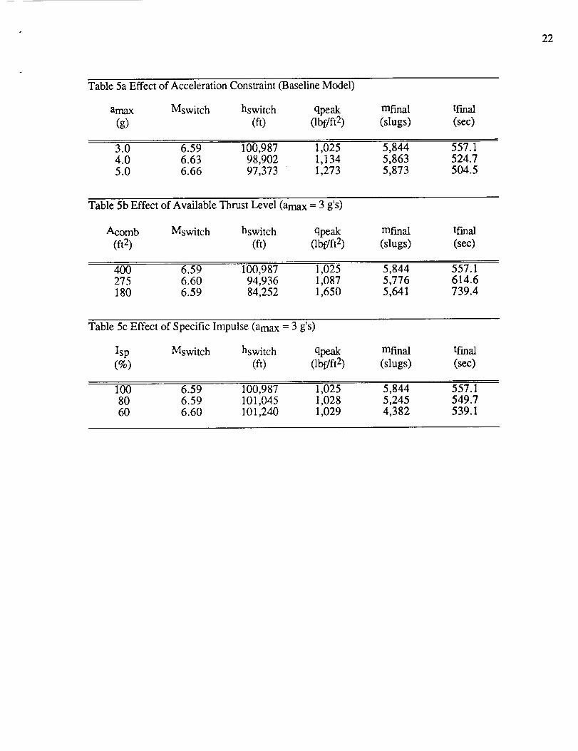
from 5g's to 3g's.The results in Table 5a show that, as expected, the performance as measured by the value
of the final mass diminishes as the acceleration constraint becomes more stringent, while the
time of ascent increases. The penalty one has to pay for the convenience of ascending to orbit at3g's as opposed to 5g's is however a meager 1,000 lbf.
Additionally, it is interesting that the Mach number and altitude at which the switch is madefrom ramjet to scramjet shows little sensitivity to the value of amax. This is also evident fromFigure 5. Referring back to Figures 1 and 2, note that the switch occurs in the Mach number
range where the Isp of the ramjet starts falling off but is still superior to the scramjet Is p whichis near its maximum value. The bottom curve in Figure 5 represents a constant dynamic
pressure of 1,500 psf. It shows that along all three ascent trajectories the dynamic pressure isless than 1,500 psf, although no dynamic pressure constraint has been imposed.
Figures 6a and b show another general characteristic: the vehicle uses full throttle unless ithas reached the acceleration constraint, in which case it throttles back in order to follow the
constraint. The same figures also illustrate the switch between propulsion modes. At both sidesof the switch the propulsion system is at full throttle. The switch occurs apparently when the
drop in Isp in going from ramjet to scramjet is outweighed by the higher scramjet thrust.Figure 7 presents the other control variable, the angle-of-attack. The character of the
angle-of-attack vs. Mach number curve is similar for the three acceleration limits. The
17
angle-of-attackis generallyhigher, the lower the accelerationlimit. Higher angle-of-attackproduceshigherlift andconsequentlythehigheraltitudeflight pathseenin Figure5.
5.2 Effect of Available Thrust Level
The combustor cross-sectional area for the baseline model roughly corresponds to a frontalintake area of 670 sqft [15]. The intake to reference area ratio of 0.112 contrasts sharply withthe area ratio of 0.0195 for the Hypersonic Research Airplane Concept of [7-10]. Although itshould be observed that the latter is a hypersonic cruise vehicle and not a SSTO boost vehicle,the discrepancy points out that the actual engine size could be determined by factors other thanair-breathing orbital insertion capability. Therefore, the available thrust level may not be quiteas high as assumed for the baseline model. Using the 300 sqft frontal intake area suggested in[11], a combustor cross-sectional area of 180 sqft is obtained. The effect of the overall thrustlevel on the minimum-fuel ascent is estimated, evaluating three engine sizes varying from the
baseline 400 sqft combustor to a 180 sqft one. A 3g's acceleration limit is employed in allthree cases.
The results in Table 5b show a 33% increase in final time, resulting in increased fuel
consumption. The propulsion mode switching still occurs in the same Mach number range,while the linear throttle exhibits the same kind of generic behavior as noted in the previous
section, see Figure 6c. However, as illustrated by Figure 8, the vehicle with the reducedengine size shows an overall tendency to fly lower at higher levels of dyn .anaic pressure. Thistendency most likely stems from the fact that thrust is proportional to dynan'uc pressure.
5.3 Effect of Fuel Specific Impulse
Presently, there is much uncertainty concerning the performance of the sub/supersoniccombustion ramjet. Therefore, it is of interest to determine what effect a drop in overall engineperformance, as expressed by the fuel specific impulse, has on the character of theminimum-fuel ascent. Employing the baseline model and again a 3g acceleration limit, threetrajectories have been determined with Isp levels ranging from 100% to 60% of our baselinevalues.
The results presented in Table 5c indicate a modest sensitivity to the engine performance asfar as trajectory make-up is concerned, with a slight increase in altitude at lower Isp (seeFigure 9), where lower ambient temperatures lead to improved performance. In contrast, theeffect on the final mass is very profound as was to be expected. The linear throttle still showsthe same generic behavior, effectively functioning as a direct acceleration control.

18
6. CONCLUSIONS AND WORK IN PROGRESS
We have developed the capability to generate constrained, minimum-fuel ascent trajectoriesfor a single-stage-to-orbit vehicle. By employing a direct solution method, state inequalityconstraints, inherent features of the ascent problem, can be routinely handled without resortingto reduced-order approximations for the vehicle point-mass dynamics. A model, based on one-dimensional flow analysis, has been developed for a multi-mode propulsion system capable ofturbojet, ramjet, scramjet, and rocket performance. The free parameters of the propulsionmodel can be adjusted to obtain a range of performance. Aerodynamic parameters have beenobtained from the GHAME. The developed capability enables us to characterize the minimum-fuel ascent trajectories. Subsequent guidance law development will be based on the results ofthe characterization.
Results pertaining to the effects of variations in acceleration constraints, available thrustlevel and fuel specific impulse on the shape of the minimum-fuel ascent trajectories have beenobtained. The results show that, if the airbreathing engines are sized for acceleration to orbital
velocity, it is the acceleration constraint rather than the dynamic pressure constraint that isactive during ascent. Realistic acceleration constraints can be accommodated by properadjustment of the throttle and angle of attack with only minor mass penalties. The accelerationconstraint is accommodated by increasing the angle of attack to raise the flight path during
potentially high acceleration periods and throttling back when the acceleration limit is reached.There are finite trajectory segments on the acceleration boundary. The response to decreasingthe level of available thrust is that the vehicle flies uniformly at lower altitude; the flight time is
increased, as is the fuel consumption. Changing the Isp has little effect on the optimal trajectoryand controls, but does increase the fuel consumption as expected.
Our initial minimum-fuel trajectory results showing acceleration to be the limiting, constraintare inconsistent with those of other investigators [2,22,28] who have found dynamic pressureto be the limiting constraint. Since the work reported in Chapter 5 was completed, a revisedscramjet model has been developed. This revised model allows us to investigate the effect ofthrust roll-off at high speeds on the characteristics of the minimum-fuel ascent. We arecurrently computing minimum-fuel trajectories, for which the rocket engine is allowed to
augment the air-breathing thrust capability during the ascent. With this approach, we avoidhaving to size the air-breathing engines for acceleration to orbital velocit.y. As discussed inSection 5.2, lower air-breathing engine thrust levels lead to higher dynamic pressures. Thuswe should obtain results that are more in line with those of other investigators.
We also intend to investigate the effects of making the thrust level dependent on
angle-of-attack or the thrust pitch angle. Scaling the thrust by a quadratic function of angle ofattack will allow us to investigate several types of thrust variation by using different values ofthe coefficients in the quadratic function. For the proposed type of air-breathing SSTO vehicleswhere the fore- and aftbody of the vehicle constitute integral parts of the propulsion system, thedirection of thrust will vary with flight conditions. We plan to develop a means simulating thisfeature and then to determine the consequences.
Much useful insight into the characteristics of the minimum-fuel ascent trajectories has beengained using reduced-order models [22,28]. An important question that needs to be answeredis: How well do the optimal trajectories for the reduced-order models approximate the optimaltrajectories for the full-order model? We intend to answer this question and are proceeding todevelop software to generate reduced-order solutions.
Finally, we plan to spend much of the next year on initial guidance law development.

19
REFERENCES
[18][191[20][21][22]
[23][24]
[1] Donaldson, P., "Developing Air-Breathers", Space, Vol. 4, No. 4, July-Aug. 1988.[2] Schoettle, U.M., "Performance Analysis of Rocket-Ramjet Propelled SSTO
Vehicles", 36 th Congress of the International Astronautical Federation, Stockholm,Sweden, Oct. 7-15, 1985, IAF-85-133.
[3] Miele, A., Flight Mechanics, Vol.1 Theory of Flight Paths, Addison-WesleyPublishing, 1962.
[4] Vinh, N. X., Busemann, A., and Culp, R. D., Hypersonic and Planetary Entry
Flight Mechanics,University of Michigan Press, Ann Arbor, 1980.[5] "U.S. Standard Atmosphere, 1976", U.S. Government Printing Office, 1976.
[6] Bryson, A. E., Jr. and Ho, Y. C., Applied Optimal Control, HemispherePublishing Corporation, New York, 1975.
[7] Penland, J.A., Fournier, R.H., and Marcum, Jr., D.C.,"AerodynamicCharacteristics of a Hypersonic Research Airplane Concept Having a 70 ° SweptDouble-Delta Wing at Mach Numbers From 1.50 to 2.86", NASA TN D-8065,1975.
[8] Dillon, J.L., and Pittman, J.L., "Aerodynamic Characteristics at Mach NumbersFrom 0.33 to 1.20 of a Wing-Body Design Concept for a Hypersonic Research
Airplane", NASA Technical Paper 1044, 1977.[9] Dillon, J.L., and Pittman, J.L., "Aerodynamic Characteristics at Mach 6 of a
Wing-Body Design Concept for a Hypersonic Research Airplane", NASA Technical
Paper 1249, 1978.[10] Penland, J.A., Hallissy, J.B., and Dillon, J.L., "Aerodynamic Characteristics of a
Hypersonic Research Airplane Concept Having a 70 ° Swept Double-Delta Wing atMach Numbers From 0.80 to 1.20, With Summary of Data From 0.20 to 6.0",
NASA Technical Paper 1552, 1979.[11] Bowers, A.H., and Iliff, K.W., "A Generic Hypersonic Aerodynamic Model
Example (GHAME) for Computer Simulation", 1988, Proposed NASA TM.[12] Aviation Week & Space Technology, June 26, 1989, pg. 37-38.
[13] Loh, W.H.T. ed., Jet, Rocket, Nuclear, Ion and Electric Propulsion: Theory
and Design, Springer-Verlag New York Inc. 1968.[14] Swithenbank, J., "Hypersonic Air-Breathing Propulsion", Progress in Aeronautical
Sciences, Vol.8, 1967, pp.229-294.[15] Small, W.J., Weidner, J.P., and Johnston, P.J., "Scramjet Nozzle Design and
Analysis as Applied to a Highly Integrated Hypersonic Research Airplane", NASATN D-8334, 1983.
[16] Kerrebrock, J.L., Aircraft Engines and Gas Turbines, The MIT Press, 1977.
[17] Cohen, H., Rogers, G.F.C., and Saravanamuttoo, H.I.H., Gas Turbine Theory,Longman, 1984.Whittle, F., Gas Turbine Aero-Thermodynamics, Pergamon Press, 1981.Hurd, R. "Supersonic Inlets", AGARDograph 102, 1969.Aviation Week & Space Technology, June 26, 1989, pg. 79.Aviation Week & Space Technology, July 10, 1989, pg. 11.Calise, A.J., Flandro, G.A., and Corban, J.E., "Trajectory Optimization andGuidance Law Development for National Aerospace Plane Applications", Final
Report for Period July 1, 1987 to November 30, 1988, NASA CR NumberNAG-I-784, 1988."Jane's All the World's Aircraft", J.W.R. Taylor ed., Franklin Watts, 1976.
Hargraves, C.R., Pads, S.W., and Galley, J.W., Optimal Trajectories by ImplicitSimulation Manual, Vol. I-IV, 1988, AFWAL TR-88-3057.
20
[25] Hargraves,C.R. andParis,S.W., "Direct TrajectoryOptimizationUsing NonlinearProgrammingandCollocation",Journalof Guidance,Control andDynamics,Vol.10,No. 4, July-Aug. 1987.
[26] Gill, P.E., Murray, W., andWright, M.H., Practical Optimization, AcademicPress,1981.
[27] Gill, P.E., Murray, W., Saunders,M.A., and Wright, M.H., "User's Guide forNPSOL (Version 2.1): A FORTRAN Packagefor Nonlinear Programming",Technical Report SOL 84-7, SystemsOptimization Laboratory, DepartmentofOperationsResearch,StanfordUniversity,Stanford,CA, September1984.
[28] Corban,J.E., Calise,A. J.,andFlandro,G. A., "OptimalGuidanceandPropulsionControl for Transatmospheric Vehicles," Paper 89-3617, AIAA Guidance,Navigation,andControlConference,Boston,MA, August1989.

21
Table1RamjetModeEngineParameters
IntakeKinematicEfficiencyCombustorEntryMachNumberCombustionEfficiencyCombustorStagnationPressureLossCombustorStagnationExit TemperatureNozzleVelocityCoefficientNozzleExit-CombustorCrossSectionAreaRatio
0.940.5
0.963%
2500K0.97
6
Table2 ScramjetModeEngineParameters(OriginalModel)
IntakeProcessEfficiencyDiffusionRatioMo]M3CombustionEfficiencyNozzleVelocityCoefficientNozzleExit-CombustorCrossSectionAreaRatio
0.933
0.960.96
6
Table3 ScramjetModeEngineParameters(RevisedModel)
IntakeProcessEfficiencyDiffusionRatioM0]M3CombustorAreaChangeParameter
CombustionEfficiencyNozzleVelocityCoefficientNozzleExit-CombustorCrossSectionAreaRatio
E= 0.0E =(M-3)/7.7E= 1.0
0.923
M < 3.03.0 <M < 10.7
M > 10.70.93
0.93/0.916
Table 4a Initial Conditions
Mass 9013.5 slugsMach Number 2.0
Dynamic Pressure 1,000 lbf/ft 2
Table 4b Final Conditions
Altitude 259,000 ft
Velocity 25,777 ft/secFlight Path Angle 0.0 o
Table 4c Baseline Vehicle Model
Gross Take-Off Weight
Reference Area
Combustor Cross Section Area
Fuel Specific Impulse
300,000 lbf
6,000 ft 2
400 ft2100%
22
Table5aEffectof AccelerationConstraint03aseline Model)
amax Mswitch hswitch qpeak
(g) (ft) (lbf/ft 2)
mfinal
(slugs)
tf'mal
(sec)
3.0 6.59 100,987 1,025 5,844 557.14.0 6.63 98,902 1,134 5,863 524.75.0 6.66 97,373 1,273 5,873 504.5
Table 5b Effect of Available Thrust Level (amax = 3 g's)
Acomb Mswitch hswitch qpeak
(ft 2) (ft) 0bf/ft 2)
mfinal
(slugs)
tfmal
(sec)
400 6.59 100,987 1,025 5,844 557.1275 6.60 94,936 1,087 5,776 614.6180 6.59 84,252 1,650 5,641 739.4
Table 5c Effect of Specific Impulse (amax = 3 g's)
Isp Mswitch hswitch
(%) (ft)
qpeak(lbf/ft 2)
mfinal
(slugs)
tfmal
(sec)
100 6.59 100,98780 6.59 101,04560 6.60 101,240
1,0251,0281,029
5,8445,2454,382
557.1549.7539.1

23
0.7 -
GHAME AERODYNAMICS
m
0.5
0.3
0.1
Angle-of-Attack
18 °
0
I 1 I I ! I
5 10 15
Mach Number
I I I
20 25
0.24 -
GHAME AERODYNAMICS
0.18 -
_D
¢.9
_ 0.12r..)
_ _
0.06
/Angle-of-Attack
I I I I I I I
0 5 10 15
Mach Number
I I I
20 25
Figure 1 Aerodynamic Characteristics

24
28OOO
_r 21000
._ 140OO[-o
oo 7000
0
RAMJET
2 4 6
Mach Number
RAMJET
6OOO50 lift us'76 SA
0 '
0 2 4 6
Mach Number
Figure 2 Ramjet Characteristics

25
100
75
v===l
"-" 50
t...,
¢Duz 25• i.=.1r,9
0
SCRAM JET
lOO kft US'76 S
_150 kft US'76 SA .._--
J_ i i i i i
0 8 16 24
Mach Number
I
32
C9
E
800 -
2100 -
1400-
700-
SCRAM JET
100 kft US'76 SA
150 kft US'76 SA
I I I t I I
0 8 16 24
Mach Number
I
32
Figure 3 Scramjet Characteristics (Original Model)

26
§
¢.9t_* i,,,_
m
0 --
0
0
SCRAMJET
flookf__s76sAI
93'8 16 24
Mach Number
!
32
¢9 3000 -
ct_
2000-
¢.)
1000 -
0
SCRAM JET
100 kft US'76 SA I
=0.93 [
0 8 16 24 32
Mach Number
Figure 4 Scramjet Characteristics (Revised Model)

27
\
[.-,
Z .................
<
m','_
II
<
!I
...............k" ..........i.................i..................co
7
OJ"4) zpnl!llV
Figure 5 Effect of Acceleration Constraint on the Altitude Profile

28
3.5 --
3
2.5
o=.=_
1.5
0.5
0
0
I
4
THRUST CONTROL
ll0
hrottle - 100
Acceleration _ 70
\Acc._mit-_I _
I I ; I I I 50
8 12 16 20 24 28
Mach Number
THRUST CONTROL
5.5
4.5 N Throttle
_ 2.5
_ 2_ 1.5
o.5 II I I I I I
0 4 8 12 16 20 24
Mach Number
- 110
- 100
_o_
°i70
60
50
28
Figure 6a and b Thrust Control for Minimum-Fuel Ascent

29
2.5 -
2
1.5
[.-,
0.5
0
0
THRUST CONTROL
_ rottle
Acceleration _
Acomb = 180 sqft ]
Acc. Limit = 3g I "_I I I I I I
4 8 12 16 20 24
Mach Number
- 110
- 100
60
50
28
3.5
_
"_ 2.5 -
O°IIN
2-
"_ 1.5-
[-.,
0.5 -
0
0
THRUST CONTROL
_" rottle
t Ac____ieration
_b--%°----imit=3g _. -
I I ..... I I I I
4 8 12 16 2O 24
ll0
- 100
70
-60
50
28
Mach Number
Figure 6c and d Thrust Control for Minimum-Fuel Ascent

30
[..,Z
<
2;
>
m
.E
0
<
\
mm
I
)J
($_p) _13_llV-JO-OI_uv
g_
_5
oO
Figure 7 Effect of the Acceleration Constraint on the Angle-of-Attack

31
r/2
Z
r..)r,¢'2<
!
2;
I
, i
................. } .............. !"" _
N.
[.-.
"N
<
II
.i.................L....._.N.
(lPI) opm!llV
O0
cD
Figure 8 Effect of Available Thrust Level on the Altitude Profile

32
r_
Z
r..)r_
<
!
\ /
OJ'4) opm!llV
tD
2:
oo
Figure 9 Effect of Fuel Specific Impulse on the Altitude Profile
33
APPENDIX
A.0 INTRODUCTION
The purpose of this propulsion model is to render the maximum thrust (T) and specific
impulse (Isp) as a function of Mach number (M) and altitude (h) in a standard atmosphere,covering theentire flight envelope of an air-breathing SSTO vehicle.
The aero-engine for such a vehicle comprises several distinct propulsion modes, eachsuited to operate over a specified speed range. The propulsion model consists of anafterburning single-flow turbojet, a ramjet and a scramjet. The mechanical details of how thesemodes are to be integrated into one device will not be discussed in what follows. It is tacitlyassumed that such an engine can be construed.
The respective modes are analyzed using simple one-dimensional flow analysis for perfectgasses, employing constant efficiencies throughout the engine. The key however, is to use themost appropriate ones, i.e. to use those efficiencies that remain more or less constant over the
operating range.
A.1 AMBIENT AND FREE-STREAM CONDITIONS
The ambient conditions, i.e. pressure (Pa), temperature (Ta) and speed of sound (a), arecompletely determined by the altitude in a standard atmosphere. In the current implementation,the U.S. Standard Atmosphere, 1976 is being used [4].
The ambient conditions together with the free-stream Mach number determine theflee-stream stagnation pressure (PRO) and stagnation temperature (Tto)
Pt0=P0 1+ M • o= o(1(A1)
A.2 THE AFTERBURNING TURBOJET
The basic components of a afterburning turbojet (Figure A1) consist of an intake,compressor, combustion chamber or burner, turbine, afterburner and a nozzle.
In the performance assessment of a turbojet one needs to make a distinction between theoperation of the engine at its design point and away from it. Since the SSTO vehicle isaccelerating to Earth-orbit, it operates over a wide range of velocities and altitudes. The off-design operation of the engine is therefore its "true" operating condition and should besatisfactorily modeled.
First, the design point operation is analyzed for fixed design parameters such as
compressor pressure ratio (Ecdes), turbine entry temperature (TET) and nozzle expansion ratio.Subsequently, using some realistic assumptions about the turbojet operation, estimates can be
found for the off-design compressor pressure ratio (ec) and ditto mass flow (m), which are
adequate for this simple model.

A.2.1 The Intake
The intake compresses the air and reduces its velocity, thereby raising its static temperature.In general, the Mach number should be in the range of 0.3 to 0.5 at the compressor inlet. Theintake-diffusion is assumed to be adiabatic, since the diffusion takes place very rapidly. Hence
the stagnation temperature remains constant, that is Tt2=Tt0.Due to imperfect diffusion, a drop in stagnation pressure will generally occur. At high
velocities the intake efficiency is best specified by a constant kinetic efficiency
For a well designed intake TIKE = 0.94 to 0.97, [13,16]. The intake pressure recovery ratio isthen specified by
=( r-1Pt2 [I+(I-rIKE)--_M0)11R - Pt0
Y
y-I
(A3)
During off-design operation a fixed-geometry intake would incur spillage drag as aconsequence of changes in the mass flow, in addition to a reduction in efficiency. However,here it is reasonable to assume that for such an advanced vehicle as an aerospace plane, a
sophisticated variable-geometry intake will be installed, to avoid spillage drag while providingthe mass flow to match the engine. In other words, in the current model it is assumed that theintake itself does not exhibit any off-design behavior (easier stipulated than realized).
A.2.2 The Compressor
The compressor provides an additional rise in pressure. The compressor pressure ratio is adesign parameter.
] = 15(E c) des 0mSA ,static
according to [16].Assuming a constant engine speed, there is a constant volume flow through the engine due
to the constant axial velocity through the compressor [13]. Employing a constant isentropic
compressor efficiency (rlc=0.96), it can be shown that the off-design pressure ratio is given by
ec=/1-_c+J_2+T"m---AD] '/-1Tt0(A4)
34
where

35
D= ec"1' -1 2TIc+Ec"1' -1(A5)
A constantisentropic efficiency has been used as opposed to the more suitable (i.e. morerealistically constant) polytropic efficiency, in order to be able to obtain a closed-form
expression for the pressure ratio.The compressor exit temperature (Tt3) is determined by
T =Tt3
1+t2
T
EY-]_Ic
TI c (A6)
The constant volume flow, combined with a constant intake delivery speed of 150 rn/s to170 m/s [18], allows one to determine the specific mass flow per unit compressor area
m P2- V
A RT 2c 2 (A7)
Thus, as will become apparent later, the compressor inlet area constitutes the engine sizingparameter which scales the thrust linearly.
A.2.3 The Combustion Chamber
In view of its purpose, this model is not concerned with the intricacies of the combustionprocess itself. Instead, simple heating relations for a perfect gas are used with a given heatingvalue of the fuel. In this particular case, hydrogen is used in all three propulsion modes.
For maximum thrust, heat must be added up to the limit set by the TET, approximately1600 to 1700 K. For the specific fuel flow one obtains
TET - Tt3
fb = TIbHTET
CP av (A8)
The burning efficiency TIb is a correction factor for imperfect combustion, a typical value is
0.96 [13,17]. H is the heating value of the fuel, H = 144.6 106 J/kg. An inevitable
by-product of the heat addition is a loss in stagnation pressure. A reasonable estimate is 3% to7%. [13].
A.2.4 The Turbine
In the turbine the gas provides the work needed for compression.
c Pair(Tt3- Tt2 ) :rlrnC Pgas(1 +fb)(TET - Tt5) (A9)
where TIm represents a mechanical efficiency factor for the turbo-machinery, Tim -_ 0.99.
Employing constant isentropic turbine efficiency TIt, the pressure ratio is determined by
36
I TET -Tt5] "¢- 1Pts_ 1- fE-f, (A10)
A.2.5 The Afterburner
The afterburner increases the specific thrust considerably, an important consideration for a
boost vehicle like an aerospace plane. Since the afterburner is not followed by any rotatingmachinery the exit temperature (Ttexit) can be higher than the TET. A reasonable value is 2000K, [161.
The specific fuel flow is given by
-TT t exit t 5
fab= r 1 bH
c TtP av exit
(1 +fb)
(A11)
Again, a slight drop in stagnation pressure is inevitable.
A.2.6 The Nozzle
A straightforward sensitivity analysis will show that, for optimal performance, one needsto install a convergent-divergent nozzle (also known as a condi nozzle) on a high performancevehicle, in order to let the gas expand to near ambient pressure. The decrease in performance,using only a convergent nozzle becomes especially noticeable at supersonic speeds. However,an upperlimit should, realistically, be imposed on the expansion ratio ER=Aexit/Athroat inaccordance with engine size limitations.
From the known mass flow through the engine one can determine the necessary throat size
Athroat m
i
A c A c (1 + fb + fah)
7+1
%/_ exit /_'/T+ 1/2(Y- 1)
Ptexi t N/-T" _---_j(A12)
Both the ideal expansion and the given mass flow imply a continuously adjustable nozzlegeometry. The exit Mach number is determined from either
M 2 2 P t exit
exit - 'y - 1 P 0(A13)
for ideal expansion Pexit=P0, or

" 37
ER-M
1 1+ M
exit Y + 12
y+l
-
exit
(A14)
for maximum expansion, where the maximum expansion ratio (ER) is determined from
ER-Aexit A c
A Ac throat
where Aexit/Ac is determined by the engine size and is taken to be approximately 4.0.Subsequently, the exit velocity is determined from
Wexit = C vMexit
_,RT t exit
(A15)
where the nozzle velocity factor Cv=0.96 is introduced to adjust for nozzle losses.The thrust per unit of compressor inlet area is determined from
T m.w'_c- Ac[ exit (1 + f b + f ab) - V01 + ER
AthroatA ( p exit - p 0)
c (A16)
and the specific impulse is given by
sp
T
AC
m
g0"_c (1 + fb + fat)(A17)
A.3 THE RAMJET
The ramjet is more or less a skeleton turbojet with the turbo-machinery taken out since thereis no need for a compressor, the ram compression by itself is effective enough. The ramjetconsists of an intake, a combustion chamber and a nozzle. All pertinent equations for thesecomponents are stated in the previous section on the afterburning turbojet. A number of (small)changes in some parameter values have been applied, consistent with the different operatingrange of the engine.
The intake delivery Mach number has been set to a constant value of 0.5. The massflow
equation (A7) must now be restated in terms of constant intake delivery Mach number

38
A-5- M2(A18)
The exit temperature has been raised to 2500 K, while the nozzle exit to combustor inlet arearatio Aexit/Ac has been raised to 6.0 to boost performance.
A.4 THE SCRAM JET
The scramjet is very similar to the ramjet. The main difference is that the combustion takesplace while the air is moving at supersonic velocities. The reason to apply supersoniccombustion is to avoid the excessive losses in stagnation pressure, which are introduced first,when the air is decelerated by means of an intake to subsonic velocities for combustion, andafterwards, when it is accelerated again by means of a nozzle to supersonic velocities. Aschematic diagram of a scramjet is presented in Figure A2.
A.4.! The Intake
For operation at very high velocities reference [14] suggests using a different type of
process efficiency, which more nearly stays constant: KD = 0.93. It can be shown that thekinetic efficiency is reIated to KD by
I]KE= KD2
+(1-KD) tVo ) (A19)
and llK E determines the recovery pressure ratio in the usual way. Additionally, the intakedelivery Mach numbers are now supersonic. The recommended diffusion ratio _/M 3 is about3.0 for optimal fuel specific impulse.
A.4.2 The Combustion Chamber
Combustion in a combustor with constant cross section area leads to adequate performanceat high speeds. However, at the lower speed range constant cross section area combustionleads to thermal choking and rapid degradation of performance. To avoid this one needs toemploy a variable cross section area combustor. A straightforward implementation of such ascheme however, would increase the complexity of the model beyond the sought after relative
simplicity. A particularly elegant way to circumvent this problem is to employ the followingrelation between static pressure and combustor area
E
P3 tAg) (A20)
Setting E equal to 1.0, one obtains the constant cross section area flow, while setting E equalto 0.0 results in constant pressure flow, which in principle cannot choke. By using the aboverelation with linearly increasing E from 0.0 to 1.0 over the Mach number range from 3.0 to11.0, one can alleviate the performance degradation.

39
Theequationsfor one-dimensionalflow with heatadditionemploying(A20)canbefoundin [13]. Given the initial state(M3, Pt3,Tt3) and a certainheatinput asdeterminedby thefuel-to-airratio fb, thef'malstate(M5,Pt5,Tt5)canbefound.
T t5 =
rlbH fTt3 + Cpa v b
l+fb-(A21)
The Mach number at the burner exit can be found from
i 212 - 2
Tt5_ M 5 E+yM 3 I+_-_M 5
Tt3 M3 E+-_5) i+-_ M23(A22)
and the stagnation pressure from
Pt5 = E+yM23 +--2--
7
7-1
(A23)
An optimal fuel-to-air ratio as a function of free-stream Mach number is obtained from
Swithenbank [Fig. 10, Ref. 14]. Therefore the final state of the gas can be determined. Incase the fuel mixture scheme leads to thermal choking the amount of fuel is reduced to thecritical amount. The critical fuel-to-air ratio is determined employing (A20) and (A21) inreverse order, substituting M5=l.0 into (A21) to obtain Tt5 and using (A20) next to evaluatefb. The supersonic combustion process, i.e. adding heat at supersonic velocities, leadsunavoidably to a large stagnation pressure loss. However the loss is significantly smaller thanif subsonic combustion had been used.
A.4.3 The Nozzle
In this case, since the flow is already supersonic, the nozzle consists of a divergent sectiononly. Again, as with the turbojet and ramjet, the expansion ratio is limited. A value of 6.0 forthe AexiJAc ratio seems reasonable (cf. [15]). The exit Mach number is determined from
I _ M 2
A exit _ M 5 1 + -_ exit
A c M exit 1 + M 5
7+1
2(T - 1)
(A24)
and the exit velocity is determined from the pertinent equation as stated in the turbojet nozzlesection. The same remark applies to the specific thrust (here, referenced to the combustor cross
section area) and the Isp.

40
A.5 CONCLUSION
Again, it should be stressed that the described model is one of relative simplicity and it doesnot occupy itself with the particular details of engine design. However, it adequately describesthe tendencies of a true multi-mode engine and provides us with a sufficient number ofparameters to tinker with and refine the modeled engine behavior over a wide range of vehicleoperating conditions.

41
Combustor
Intake Compressor Turbine Nozzle
iiiiiiiili!iiI
1 2 3 4 5 Throat Exit
Figure A1 Basic Components of a Turbojet
Intake Combustor Nozzle
1 3 5 Exit
Figure A2 Basic Components of a Scramjet