training report on study of engine …...training report may 2011 – june 2011 page 8 1. cylinder...
TRANSCRIPT

TRAINING REPORT ON
STUDY OF ENGINE COMPONENTS,ENGINE
ASSEMBLY AND PRODUCTION SYSTEM
MENTORED BY
Mr. Abhijit Lakshman
(Assistant Manager, EPD)
Suzuki Powertrain India Limited
SUBMITTED BY
Gaurav Kumar
Department of Mechanical Engineering
National Institute of Technology, Silchar

Suzuki Powertrain India Limited
Training Report
May 2011 – June 2011
Page 2
ACKNOWLEDGEMENTS
First of all I would like to thank SUZUKI POWERTRAIN INDIA LIMITED for providing me an
opportunity to have an industrial exposure under the guidance of the experts and I am sure it
would definitely help to mould me into a more competent & better skilled engineer.
I would like to convey my sincere gratitude to Mrs. Chanchala Mistry(HR) and Ms. Usha(HR) for
providing me the opportunity and their guidance during the tenure of training.
I sincerely thank Mr. Abhijit Laxman(Asst. Manager, EPD) for taking me under his able
mentorship and Mr. Pramod Kumar(Engineer, EPD) for guiding me during the completion of my
Project.
I would also like to thank all of them who have directly or indirectly helped me during the
tenure of training.
Sincerely thanking all of the above mentioned once again, I hope to take guidance from the
aforementioned in the near future. It has been a great experience for me.
GAURAV KUMAR
DEPARTMENT OF MECHANICAL ENGINEERING
NATIONAL INSTITUTE OF TECHNOLOGY, SILCHAR

Suzuki Powertrain India Limited
Training Report
May 2011 – June 2011
Page 3
DECLARATION
I hereby declare that I have successfully completed 24 days Industrial training scheduled from
28/05/2011 to 20/06/2011 under the Engine Production Department of SUZUKI POWERTRAIN
INDIA LIMITED.
Apart from Industrial training I have also worked on a project entitled “IMA CASE STUDY”
which is an authentic record of my work carried out at SUZUKI POWERTRAIN INDIA LIMITED.
(GAURAV KUMAR)
DEPARTMENT OF MECHANICAL ENGINEERING
NATIONAL INSTITUTE OF TECHNOLOGY, SILCHAR
It is certified that the above statements made by the trainee is correct to the best of our
Knowledge.
(ABHIJIT LAKSHMAN) (R.K. GUPTA)
(ASST. MGR, EPD) (H.O.D., EPD)
SUZUKI POWERTRAIN INDIA LIMITED SUZUKI POWERTRAIN INDIA LIMITED

Suzuki Powertrain India Limited
Training Report
May 2011 – June 2011
Page 4
CONTENTS
CHAPTERS PAGE NO.
ABSTRACT 5
ABOUT SPIL 6
PROCESS FLOW – ENGINE PLANT 9
BASICS OF DIESEL ENGINE 10
ENGINE COMPONENTS AND ITS DESCRIPTION 12
THE FUEL INJECTION SYSTEM 33
INTRODUCTION TO PIKA-PIKA SYSTEM AND DATA CYCLE 39
DATA-CHARTS 41
TESTING OF ENGINE ASSEMBLY 45
PROJECT: IMA CASE STUDY 48
CONCLUSION 58

Suzuki Powertrain India Limited
Training Report
May 2011 – June 2011
Page 5
ABSTRACT
I had an opportunity to undergo a vocational training for 31 days dated from 30/05/2011 to
29/06/2011 in SPIL, Gurgaon at Manesar plant. During the period of training I had an exposure
to various on-going processes and procedures in the engine production and assembly section
of the organization. I got an opportunity to discuss and learn a lot about the industrial
processing and development activities of SPIL.
There are basically four main divisions in the organization viz. The machining division, the
assembly division, the transmission division and the casting division. During the entire tenure
of the training my main focus was laid on the Engine Assembly
The Engine Assembly line is mainly divided into:-
1. The short block line
2. The long block line
3. The cold test area
4. The dressing line
5. The hot test area
6. M-series Engine assembly line
Apart from getting the overview of all the above mentioned procedures, I also worked on a
small project on IMA barcode mismatch and damage data representation, Investigation of the
root cause and suggesting solution for the problem.

Suzuki Powertrain India Limited
Training Report
May 2011 – June 2011
Page 6
ABOUT SUZUKI POWERTRAIN INDIA LIMITED
HISTORY
SUZUKI MOTOR CORPORATION (SMC)
The company lead its foundation in1909 as SUZUKI LOOM WORKS, It was reorganized,
incorporated and capitalized with 500,000 yen as SUZUKI LOOM MANUFACTURING Co. with
Michio Suzuki as president in1920. Later on the company renamed as SUZUKI MOTOR
CORPORATION LIMITED in 1954.
MARUTI SUZUKI INDIA LIMITED (MSIL)
The company was incorporated in February 1981, it was an agreement signed between
MARUTI UDYOG LIMITED & SUZUKI MOTOR CORPORATION in 1982, later on the name
changed from MARUTI UDYOG to MARUTI SUZUKI INDIA LIMITED in September 2007.
SUZUKI POWERTRAIN INDIA LIMITED (SPIL)
The power train is named so because it is a conjunction of two words:
POWER- for power generation
TRAIN –for power transmission
SUZUKI POWERTRAIN INDIA LIMITED is a joint venture between SUZUKI MOTOR
CORPORATION and MARUTI SUZUKI INDIA LIMITED, with the investment ratio of 70:30.
Company was set-up in year 2002 as SUZUKI METAL INDIA LIMITED operating its casting plant
unit. It was renamed as SUZUKI POWERTRAIN INDIA LIMITED in June 2005. Project set-up for
engine & transmission plant was started in year 2005 & 2006 respectively with the main aim to
produce the world’s finest diesel engine & transmission.
This is SUZUKI’s first such facility anywhere in world. This stage of the art plant produces world
class diesel engines, petrol engines, castings and transmission for cars. This facility had an
initial capacity to manufacture 100,000 diesel engines per year, now the aim is to expand the
expansion to 900,000 per year.
Suzuki Powertrain India Limited
Training Report
May 2011 – June 2011
Page 7
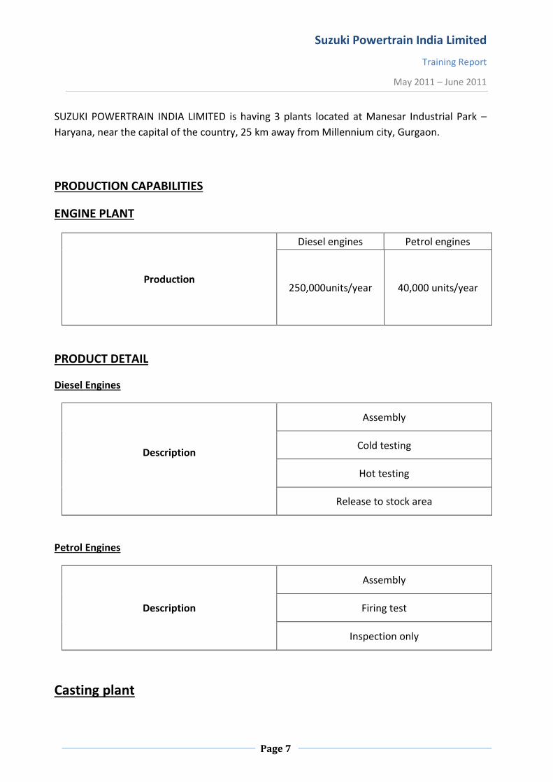
SUZUKI POWERTRAIN INDIA LIMITED is having 3 plants located at Manesar Industrial Park –
Haryana, near the capital of the country, 25 km away from Millennium city, Gurgaon.
PRODUCTION CAPABILITIES
ENGINE PLANT
Production
Diesel engines Petrol engines
250,000units/year 40,000 units/year
PRODUCT DETAIL
Diesel Engines
Description
Assembly
Cold testing
Hot testing
Release to stock area
Petrol Engines
Description
Assembly
Firing test
Inspection only
Casting plant

Suzuki Powertrain India Limited
Training Report
May 2011 – June 2011
Page 8
1. Cylinder head – 22,500 per month
2. Bed plate – 22,500 per month
3. Cam carrier – 22,500 per month
4. Transmission case – 87,000 per month
Description
Gravity die casting
High pressure die casting
Transmission plant
Description
Forging – Machining – Heat treatment – Assembly – Inspection
Components
Mission gear (9 types)
Input and counter shaft (2 types)
Sleeve (3 types)
Mission cases right and left
Production
Transmission carrier Two-wheeler
10,00,000 units/year 60,000 units/year

Suzuki Powertrain India Limited
Training Report
May 2011 – June 2011
Page 9
PROCESS FLOW – ENGINE PLANT
The total process can be divided into two parts namely machining and assembly.
Machining Section
1. Cylinder Block
2. Bed Plate
3. Crankshaft
4. Cylinder Head
5. Cam Carrier
6. Camshaft
After the machining operation the components are dispatched to their respective assembly
line.
The assembly line under engine plant is the “Engine Assembly Line”.
First six aforementioned components are assembled in the Engine assembly line, the engine is
passed through rigorous tests viz. cold testing and hot testing to clear out any undesirable
functioning of the engine and after ensuring the smooth and satisfactory functioning under the
different testing load conditions final inspection is performed and then dispatched to the
Maruti Suzuki India Limited – Manesar plant.

Suzuki Powertrain India Limited
Training Report
May 2011 – June 2011
Page 10
BASICS OF DIESEL ENGINE
Since the same process occurs in each cylinder, we will take a look at one cylinder to see how
the four stroke process works. The four strokes are Intake, compression, Power and Exhaust.
The piston travels down on the Intake stroke, up on the Compression stroke, down on the
Power stroke and up on the Exhaust stroke.
Intake
As the piston starts down on the Intake stroke, the intake valve opens and the fuel-air mixture
is drawn into the cylinder. When the piston reaches the bottom of the intake stroke, the intake
valve closes, trapping the air-fuel mixture in the cylinder.
Compression
The piston moves up and compresses the trapped air fuel mixture that was brought in by the
intake stroke. The amount that the mixture is compressed is determined by the compression
ratio of the engine. This means that when the piston reaches the top of the cylinder, the air-
fuel mixture is squeezed according to the compression ratio. For diesel engines it is about 14:1
to 16:1 in normal cases.
Power
The spark plug fires, igniting the compressed air-fuel mixture which produces a powerful
expansion of the vapor. The combustion process pushes the piston down the cylinder with
great force turning the crankshaft to provide the power to propel the vehicle. Each piston fires
at a different time, determined by the engine firing order. By the time the crankshaft
completes two revolutions, each cylinder in the engine will have gone through one power
stroke.
Exhaust
With the piston at the bottom of the cylinder, the exhaust valve opens to allow the burned
exhaust gas to be expelled to the exhaust system. Since the cylinder contains so much
pressure, when the valve opens, the gas is expelled with a violent force (that is why a vehicle
without a muffler sounds so loud.) The piston travels up to the top of the cylinder pushing all
the exhaust out before closing the exhaust valve in preparation for starting the four stroke
process over again.

Suzuki Powertrain India Limited
Training Report
May 2011 – June 2011
Page 11
Diesel cycle
Fig. The diesel cycle
Diesel engines rely solely on compression. The piston rises, compressing the air in the cylinder;
this, by natural effect, causes the air's temperature to rise. By the time the cylinder reaches the
top of its travel path, the temperature in the cylinder is very high. The fuel mist is then sprayed
into the cylinder; it instantly combusts, forcing the piston downwards, thus generating power.
The pressure required to heat the air to that temperature, however, necessitates the use of a
large and very strong engine block
Suzuki Powertrain India Limited
Training Report
May 2011 – June 2011
Page 12
ENGINE COMPONENTS AND ITS DESCRIPTION
MAIN ENGINE COMPONENTS
THE BED PLATE
The Bedplate is the foundation on which the 4 stroke engine is built. It must be rigid enough to
support the weight of the rest of the engine, and maintain the crankshaft, which sits in the bearing
housings in the transverse girders, in alignment. At the same time it must be flexible enough to
hog and sag with the foundation plate to which it is attached and which forms part of the ships
structure.
If the bedplate was too rigid, then the holding down bolts, which secure the engine, would be
likely to break, and there would be a danger of the bedplate cracking.
Basically the bedplate consists of two longitudinal girders which run the length of the engine.
Connecting these longitudinal girders are the transverse girders which are positioned between
each crankshaft throw, and either side of the thrust collar. Built into the transverse girders are the
main bearing pockets for the crankshaft to run in.
The main functions of the engine bedplate are as follows:
The bedplate must be strong enough for providing rigid support for the main bearings and
crankshaft. It is the main platform for accurately mounting other parts such as columns, frames
and guides which support engine cylinders, entablature and all working parts.
In large engines, must withstand heavy fluctuating stresses from operation of the engine. Collect
crankcase lubricating oil and return to drain tank for further use.
FORCES ON BEDPLATE
1. Firing load from cylinders.
2. Side thrust from guide faces.
3. Unbalanced inertia forces in the running gear.
4. Weight of engine structure and running gear.
5. Vibrations due to torque variation, shock loading.
6. Thermal Stresses due to atmospheric and lubricating oil temperature change.
In addition to withstand the above forces the bedplate should also provide an oil tight chamber to
contain the oil splash, housing for the thrust bearing, also it should be small and light to keep the
overall size and the mass of the engine to a minimum.

Suzuki Powertrain India Limited
Training Report
May 2011 – June 2011
Page 13
CYLINDER BLOCK
The term "block" refers to a piston engine cylinder block, which is the lower portion of a piston
engine containing the pistons and cylinder bores.
Fig. Cylinder block
The engine cylinder block is the basic frame of a liquid-cooled engine, whether it is the in-line,
horizontally opposed, or V-type. The cylinder block and crankcase are often cast in one piece that
is the heaviest single piece of metal in the engine. The cylinder block or engine block is a machined
casting (or sometimes an assembly of modules) containing cylindrically bored holes for the pistons
of a multi-cylinder reciprocating internal combustion engine, or for a similarly constructed device
such as a pump. It is a complicated part at the heart of an engine; with adaptations to attach the
cylinder head, crankcase, engine mounts, drive housing and engine ancillaries, with passages for
coolants and lubricants. The distance between the cylinder bores (midpoint to midpoint) cannot
easily be changed since the machining facilities would require extensive modification. Instead, the
bore is commonly varied to obtain different engine displacements. This and the minimum
thickness of material required between two cylinders are a limiting factor concerning the potential
displacement because the bore to stroke ratio has to stay within certain limits. Different types of
cylinder blocks. The cylinder block is cast from gray iron or iron alloyed with other metals such as
nickel, chromium, or molybdenum. Some lightweight engine blocks are made from aluminum.
Cylinders are machined by grinding or boring to give them the desired true inner surface. During
normal engine operation, cylinder walls will wear out-of-round, or they may become cracked and
scored if not properly lubricated or cooled.
Suzuki Powertrain India Limited
Training Report
May 2011 – June 2011
Page 14
CYLINDER HEAD
The cylinder head is broadly divided into:
1. Upper cylinder head.
2. Lower cylinder head.
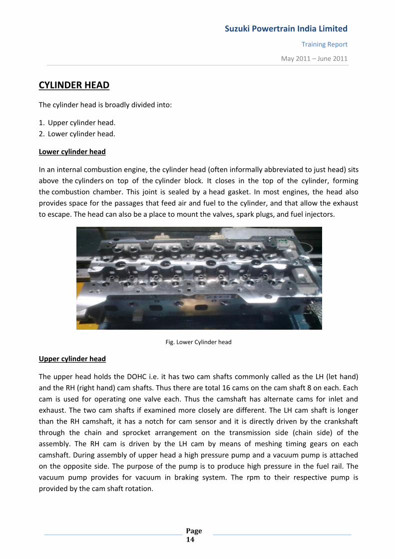
Lower cylinder head
In an internal combustion engine, the cylinder head (often informally abbreviated to just head) sits
above the cylinders on top of the cylinder block. It closes in the top of the cylinder, forming
the combustion chamber. This joint is sealed by a head gasket. In most engines, the head also
provides space for the passages that feed air and fuel to the cylinder, and that allow the exhaust
to escape. The head can also be a place to mount the valves, spark plugs, and fuel injectors.
Fig. Lower Cylinder head
Upper cylinder head
The upper head holds the DOHC i.e. it has two cam shafts commonly called as the LH (let hand)
and the RH (right hand) cam shafts. Thus there are total 16 cams on the cam shaft 8 on each. Each
cam is used for operating one valve each. Thus the camshaft has alternate cams for inlet and
exhaust. The two cam shafts if examined more closely are different. The LH cam shaft is longer
than the RH camshaft, it has a notch for cam sensor and it is directly driven by the crankshaft
through the chain and sprocket arrangement on the transmission side (chain side) of the
assembly. The RH cam is driven by the LH cam by means of meshing timing gears on each
camshaft. During assembly of upper head a high pressure pump and a vacuum pump is attached
on the opposite side. The purpose of the pump is to produce high pressure in the fuel rail. The
vacuum pump provides for vacuum in braking system. The rpm to their respective pump is
provided by the cam shaft rotation.
Suzuki Powertrain India Limited
Training Report
May 2011 – June 2011
Page 15
OVERHEAD VALVE
An overhead valve (OHV) engine, also informally called pushrod engine or I-head engine, is a
type of piston engine that places the camshaft within the cylinder block (usually beside and
slightly above the crankshaft in a straight engine or directly above the crankshaft in the V of
a V-8 engine), and uses pushrods or rods to actuate rocker arms above the cylinder head to
actuate the valves. Lifters or tappets are located in the engine block between the camshaft and
pushrods. The more modern overhead camshaft (OHC) design (still literally overhead valve)
avoids the use of pushrods by putting the camshaft in the cylinder head.
Nowadays, automotive use of side-valves has virtually disappeared, and valves are almost all
"overhead". However most are now driven more directly by the overhead camshaft system,
and these are designated OHC instead - either single overhead camshaft (SOHC) or double
overhead camshaft (DOHC).
DOHC
A double overhead camshaft valve train layout is characterized by two camshafts located
within the cylinder head, one operating the intake valves and one operating the exhaust
valves. Some engines have more than one bank of cylinder heads (V8 and flat-four being two
well-known examples) and these have two camshafts in total, but they remain SOHC, unless
each side has two camshafts. The term "twin cam" is imprecise, but will normally refer to a
DOHC engine. Not all DOHC engines are multivalve engines—DOHC was common in two valves
per cylinder heads for decades before multivalve heads appeared. Today, however, DOHC is
synonymous with multi-valve heads since almost all DOHC engines have between three and
five valves per cylinder.
The Crankshaft
The crankshaft, sometimes casually abbreviated to crank, is the part of an engine which
translates reciprocating linear piston motion into rotation. To convert the reciprocating motion
into rotation, the crankshaft has "crank throws" or "crankpins", It typically connects to a flywheel,
to reduce the pulsation characteristic of the four-stroke cycle, and sometimes a torsional or
vibrational damper at the opposite end, to reduce the torsion vibrations often caused along the
length of the crankshaft by the cylinders farthest from the output end acting on the torsional
elasticity of the metal.

Suzuki Powertrain India Limited
Training Report
May 2011 – June 2011
Page 16
Fig. Crankshaft
Radial and Axial Play
When the ball bearing is running under load, the force is transmitted from one bearing ring to the
other through the balls but since the area of contact between the balls is very small it can cause
stresses developed to be of the units of hundreds. This internal stresses have a significant impact
on the bearing life (bearing life calculated in terms of L10 or, mean life etc.) and performance and
hence the internal geometry of the bearing, the radial play, raceway curvature and contact angle
must be carefully chosen so that loads can be distributed optimally.
Most of the bearings are assembled in such a way that there is a small amount of looseness
between the ball and the raceway this looseness is referred to as the radial play and the axial play,
Axial play is the maximum relative displacement in a direction parallel to the bearing axis,
between the two rings of an un-mounted ball bearing.
The Main bearing
In a piston engine, the main bearings are the bearings on which the crankshaft rotates,
usually plain or journal bearings. All engines have a minimum of two main bearings, one at each
end of the crankshaft, and they may have as many as one more than the number of crank pins.
The number of main bearings is a compromise between the extra size, cost and stability of a larger
number of bearings and the compactness and light weight of a smaller number. Both have
advantages in terms of performance, as a shorter and more stable crankshaft will produce
better engine balance.
Selection of main bearing
Crankshaft bearings should always be replaced when you are rebuilding an engine because the
bearings are a wear component. Heat, pressure, chemical attack, abrasion and loss of lubrication

Suzuki Powertrain India Limited
Training Report
May 2011 – June 2011
Page 17
can all contribute to deterioration of the bearings. Consequently, when an engine is rebuilt new
bearings should always be installed.
"Reading" the old bearings can reveal a great deal about conditions that may have contributed to
their demise. All bearings will show some degree of wear. A close examination may reveal some
scoring or wiping, dirt or other debris embedded in the surface of the bearings, or pitting or
flaking. But when one or more crankshaft bearings are found to be damaged or show unusual or
uneven wear, it typically indicates other problems that need correcting, problems that if left
uncorrected may cause the replacement bearings to suffer the same fate.
The selection of bearing is strictly based upon the factors causing reduction in bearing life i.e. the
bearing material depends on the factors affecting the bearing life,
Some of the main causes of bearing fatigue may be :-
1. Dirt contamination causing premature bearing fatigue, fine dirt particle may get embedded into
the softer material bearing which may not be a desirable thing depending on the size of the
abrasive particle and bearing material thickness
2. Overheating is another factor causing reduction in bearing life, bearings are cooled by the oil film
present between the bearing and the journal, anything that disrupts the flow may raise the
bearing temperature and may also causing scoring or wiping the bearing.
3. Misalignment is yet another factor enhancing bearing wear, If the centre main bearings are worn
more than the ones towards either end of the crankshaft, the crankshaft may be bent or the main
bores may be out of alignment. If the crankshaft journal is not true, roundness should be checked.
4. Corrosion can also play a role in bearing failure. Corrosion results when acids accumulate in the
crankcase and attack the bearings causing pitting in the bearing surface. This is more of a problem
with heavy-duty diesel engines that use high sulphur fuel rather than gasoline engines, but it can
also happen in gasoline engines if the oil is not changed often enough and acids are allowed to
accumulate in the crankcase. Other factors that can contribute to acid build-up include a restricted
or plugged PCV system, engine operation during extremely cold or hot weather, excessive
crankcase blow by (worn rings or cylinders) or using poor quality oil or fuel.
Piston
A piston is a component of reciprocating engines, reciprocating pumps, gas compressors and
pneumatic cylinders, among other similar mechanisms. It is the moving component that is
contained by a cylinder and is made gas-tight by piston rings. In an engine, its purpose is to
transfer force from expanding gas in the cylinder to the crankshaft via a piston rod and/or
connecting rod.

Suzuki Powertrain India Limited
Training Report
May 2011 – June 2011
Page 18
Fig. Piston assembly
Gasket
A gasket is a mechanical seal that fills the space between two mating surfaces, generally to
prevent leakage from or into the joined objects while under compression. It is usually desirable
that the gasket be made from a material that is to some degree yielding such that it is able to
deform and tightly fills the space it is designed for, including any slight irregularities. A few gaskets
require an application of sealant directly to the gasket surface to function properly.
AUTOMOTIVE MANIFOLDS
INTAKE MANIFOLD
The primary function of the intake manifold is to evenly distribute the combustion mixture (or
just air in a direct injection engine) to each intake port in the cylinder heads. Even distribution
is important to optimize the efficiency and performance of the engine. It may also serve as a
mount for the carburetor, throttle body, fuel injectors and other components of the engine.
Due to the downward movement of the pistons and the restriction caused by the throttle
valve, in a reciprocating spark ignition piston engine, a partial vacuum (lower than atmospheric
pressure) exists in the intake manifold. This manifold vacuum can be substantial, and can be
used as a source of automobile ancillary power to drive auxiliary systems: power
assisted brakes, emission control devices, cruise control, ignition advance, windshield

Suzuki Powertrain India Limited
Training Report
May 2011 – June 2011
Page 19
wipers, power windows, ventilation system valves, etc. This vacuum can also be used to draw
any piston blow-by gases from the engine's crankcase. This is known as a positive crankcase
ventilation system. This way the gases are burned with the fuel/air mixture.
Fig. Intake Manifold (M-Series Engine)
EXHAUST MANIFOLD
Exhaust manifolds are generally simple cast iron or stainless steel units which collect engine
exhaust from multiple cylinders and deliver it to the exhaust pipe. For many engines, after
market high performance exhaust headers — also known as extractors — are available. These
consist of individual exhaust head pipes for each cylinder, which then usually converge into
one tube called a collector. Headers that do not have collectors are called zoomie headers, and
are used exclusively on race cars.
The most common types of aftermarket headers are made of either ceramic, or stainless steel.
Ceramic headers are lighter in weight than stainless steel, however, under extreme
temperatures they can crack - something stainless steel is not prone to.
Another form of modification used is to insulate a standard or aftermarket manifold. This
decreases the amount of heat given off into the engine bay, therefore reducing the intake
manifold temperature. The goal of performance exhaust headers is mainly to decrease flow
resistance (reverse pressure), and to increase the volumetric efficiency of an engine, resulting
in a gain in power output. The processes occurring can be explained by the gas laws,
specifically the ideal gas law and the combined gas law
Fig. Exhaust Manifold

Suzuki Powertrain India Limited
Training Report
May 2011 – June 2011
Page 20
FLYWHEEL
The purpose of the flywheel is to allow uniform engine rotation by accumulating energy during the
active phases and giving the same back halt and overcoming the friction work developed by the
same during no load operation. The flywheel has 3sub parts. A straight teeth cut at a small
diameter cylinder with a notch for crank sensor to check crank rotation and a large diameter
cylinder which meshes with the gear of the starter motor. The third part is the flywheel itself.
Fig. Flywheel
CLUTCH
A clutch is used for engaging and disengaging gears without actually stopping the engine. For the
purpose a centrifugal clutch is used. It has shoe block with friction lining and is mounted in front
of the flywheel on the crankshaft.
Working of a centrifugal clutch
A centrifugal clutch is controlled by spring force. As the engine is fired the crankshaft rotates and
the clutch rotates with it. As the throttle (rpm) increases the centrifugal force on the clutch
increases. When the spring force is equal to the centrifugal force the clutch is said to be floating.
As the throttle increases this limit the shoe block meshes with the flywheel and power is
transmitted. This meshing is further controlled by a lever which engages and disengages the
clutch.
Fig. Clutch

Suzuki Powertrain India Limited
Training Report
May 2011 – June 2011
Page 21
OIL SUMP
The oil pan of an engine contains oil, the oil is used to lubricate the engine's moving parts and it
pools in a reservoir, known as a sump, at the bottom of the engine. Use of a sump requires the
engine to be mounted slightly higher to make space for it. Often though, oil in the sump can surge
during hard cornering starving the oil pump. The oil pump is provide with a baffle plate in it to
avoid the surging and bubble formation due to the trapped air into the oil which may cause non-
desirable operation of the lubricating fluid.
Fig. Oil Sump
THE AUXILLARIES
Oil Filter
The engine needs constant lubrication to prevent friction and heat from climbing past tolerable
levels. That lubrication comes in the form of motor oil. Over time, the oil in the car's engine will
accumulate dirt, debris, and particles. If these elements gain access to your engine, they can cause
damage and early wear and tear. The obstacle that stands in their way is the oil filter (O.F.). Motor
oil is sent from the oil pump to the vehicle's crankshaft, valve-train, and other components. On its
way, it passes through the filter. It leaves behind the dirt and particles that have accumulated
since the last time oil is changed. However, if the O.F. does its job properly, it will continue to
collect debris to the point of becoming clogged. Once that happens, it’ll need to replace it.
An oil filter has two main parts. One is the filter and other is the cooler. The oil filter filters oil
while the cooler is basically circulating coolant to cool the oil. The filter also has a gateway so that
the oil can enter the oil sump when pouring oil manually.

Suzuki Powertrain India Limited
Training Report
May 2011 – June 2011
Page 22
Fig. Oil filter
The Alternator
An alternator is an electromechanical device that converts mechanical energy to electrical energy
in the form of alternating current. Most alternators use a rotating magnetic field. In principle,
any AC electrical generator can be called an alternator, but usually the word refers to small
rotating machines driven by automotive and other internal combustion engines.
Working Principle of an alternator
Alternators generate electricity using the same principle as DC generators, namely, when the
magnetic field around a conductor changes, a current is induced in the conductor. Typically, a
rotating magnet, called the rotor turns within a stationary set of conductors wound in coils on an
iron core, called the stator. The field cuts across the conductors, generating an induced emf
(electromotive force), as the mechanical input causes the rotor to turn.
The rotating magnetic field induces an AC voltage in the stator windings. The rotors magnetic field
may be produced by induction (as in a "brush-less" alternator), by permanent magnets (as in very
small machines), or by a rotor winding energized with direct current through slip rings and
brushes.
An automatic voltage control device controls the field current to keep output voltage constant. If
the output voltage from the stationary armature coils drops due to an increase in demand, more
current is fed into the rotating field coils through the Automatic Voltage Regulator or AVR. This
increases the magnetic field around the field coils which induces a greater voltage in the armature
coils. Thus, the output voltage is brought back up to its original value.

Suzuki Powertrain India Limited
Training Report
May 2011 – June 2011
Page 23
STARTER MOTOR
The modern starter motor is either a permanent-magnet or a series-parallel wound direct
current electric motor with a starter solenoid (similar to a relay) mounted on it. When current
from the starting battery is applied to the solenoid, usually through a key-operated switch, the
solenoid engages a lever that pushes out the drive pinion on the starter driveshaft and meshes
the pinion with the starter ring gear on the flywheel of the engine. The solenoid also closes
high-current contacts for the starter motor, which begins to turn. Once the engine starts, the
key-operated switch is opened; a spring in the solenoid assembly pulls the pinion gear away
from the ring gear, and the starter motor stops. The starter's pinion is clutched to its driveshaft
through an overrunning sprag clutch which permits the pinion to transmit drive in only one
direction. In this manner, drive is transmitted through the pinion to the flywheel ring gear, but
if the pinion remains engaged (as for example because the operator fails to release the key as
soon as the engine starts, or if there is a short and the solenoid remains engaged), the pinion
will spin independently of its driveshaft. This prevents the engine driving the starter, for such
reverse drive would cause the starter to spin so fast as to fly apart. However, this sprag clutch
arrangement would preclude the use of the starter as a generator if employed in hybrid
scheme mentioned above, unless modifications are made. Also, a standard starter motor is
only designed for intermittent use which would preclude its use as a generator; the electrical
components are designed only to operate for typically under 30 seconds before overheating
(by too-slow dissipation of heat from ohmic losses), to save weight and cost. This is the same
reason why most automobile owner's manuals instruct the operator to pause for at least ten
seconds after each ten or fifteen seconds of cranking the engine, when trying to start an
engine that does not start immediately.
GLOW PLUG
The problem posed with diesel engine is that in cold weather, if the engine has not been
running (as is the case when the car is left to sit overnight), that large engine block becomes
very cold; thereby the cold engine block acts as a heat sink, quickly dissipating the heat
generated by the pistons compressing air. The engine is then unable to start, because it cannot
generate and maintain enough heat for the fuel to ignite. One common and very effective
method for fixing this problem is to fit each cylinder with a glow plug. For that reason, many
smaller diesel engines come pre-fitted from the factory with glow-plugs.
Method of operation
In a diesel-engine car, unlike in a gasoline-engine car, the operator does not simply turn the
key to the "start" position and have the engine immediately start. Instead, the operator turns
the key to the "on" position; the glow plug relay switches the glow plugs on, and a light on the

Suzuki Powertrain India Limited
Training Report
May 2011 – June 2011
Page 24
instrument cluster illuminates. This process is called "pre-heating" or "glowing". If the car has
been running very recently, or if the ambient temperature is hot, the "wait to start" light may
not come on; in this case, the operator may proceed to turn the key to the "start" position and
start the engine without having to wait. A glow plug is a pencil-shaped piece of metal with a
heating element at the tip; that heating element, when electrified, heats due to electrical
resistance and begins to emit light in the visible spectrum, hence the term "glow" plug; the
effect is very similar to that of a toaster. The heat generated by the glow plugs is directed into
the cylinders, and serves to warm the of the engine block immediately surrounding the
cylinders. This aids in reducing the amount of thermal diffusion which will occur when the
engine attempts to start. Actually a glow plug consists of a resistance coil which produces high
temperature at the glow plug tip. This burns the fuel in the cylinder and hence helps to heat up
the cylinder.
Thermostat
A thermostat is a device for regulating the temperature of a system so that the system's
temperature is maintained near a desired set-point temperature. The name is derived from the
Greek words thermos "hot" and statos "a standing". The thermostat does this by switching
heating or cooling devices on or off, or regulating the flow of a heat transfer fluid as needed, to
maintain the correct temperature. A thermostat may be a control unit for a heating or cooling
system or a component part of a heater or air conditioner. Thermostats can be constructed in
many ways and may use a variety of sensors to measure the temperature. The output of the
sensor then controls the heating or cooling apparatus.
Fig. Thermostat
The Timing Chain
In the internal combustion engine application, the timing belt/chain connects the crankshaft to
the camshaft(s), which in turn controls the opening and closing of the engine's valves. A four-
stroke engine requires that the valves open and close once every other revolution of the

Suzuki Powertrain India Limited
Training Report
May 2011 – June 2011
Page 25
crankshaft. The timing belt/chain does this. It has teeth to turn the camshaft(s) synchronized
with the crankshaft, and is specifically designed for a particular engine. In some engine designs,
the timing belt may also be used to drive other engine components such as the water pump
and oil pump.
Fig. Timing chain
Gear or chain systems are also used to connect the crankshaft to the camshaft at the correct
timing. However, gears and shafts constrain the relative location of the crankshaft and
camshafts. Even where the crankshaft and camshaft(s) are very close together, as in pushrod
engines, most engine designers use a short chain drive rather than a direct gear drive. This is
because gear drives suffer from frequent torque reversal as the cam profiles "kick back"
against the drive from the crank, leading to excessive noise and wear. Fiber gears, with more
resilience, are preferred to steel gears where direct drive has to be used. A belt or chain allows
much more flexibility in the relative locations of the crankshaft and camshafts. While chains
and gears may be more durable, rubber composite belts are quieter in their operation (in most
modern engines the noise difference is negligible), are less expensive and more efficient, by
dint of being lighter, when compared with a gear or chain system. Also, timing belts do not
require lubrication, which is essential with a timing chain or gears. A timing belt is a specific
application of a synchronous belt used to transmit rotational power synchronously.
Timing belts are typically covered by metal or polymer timing belt covers which require
removal for inspection or replacement. Engine manufacturers recommend replacement at
specific intervals. The manufacturer may also recommend the replacement of other parts, such
as the water pump, when the timing belt is replaced because the additional cost to replace the
water pump is negligible compared to the cost of accessing the timing belt. In an interference
engine, or one whose valves extend into the path of the piston, failure of the timing belt (or
timing chain) invariably results in costly and, in some cases, irreparable engine damage, as
some valves will be held open when they should not be and thus will be struck by the pistons.

Suzuki Powertrain India Limited
Training Report
May 2011 – June 2011
Page 26
Indicators that the timing chain may need to be replaced include a rattling noise from the front
of the engine.
TURBOCHARGERS
A turbocharger, or turbo (colloquialism), is a Centrifugal compressor powered by
a turbine which is driven by an engine's exhaust gases. Its benefit lies with the compressor
increasing the pressure of air entering the engine (forced induction) thus resulting in greater
performance (for either, or both, power & efficiency), as greater amount of fuel are atomized
at higher temperature and more evenly mixes with the air providing a rich fuel-air mixture and
hence more power is generated. Popularly used with internal combustion engines (e.g. four-
stroke engines like Otto cycles and Diesel cycles). Turbochargers have also been found useful
compounding external combustion engines such as automotive fuel cells. Due to lighter weight
and higher power generation the power-to-weight ratio becomes high and hence almost all the
modern cars are provided with a turbocharger unit.
A turbocharger consists of a turbine and a compressor linked by a shared axle. The turbine
inlet receives exhaust gases from the engine causing the turbine wheel to rotate. This rotation
drives the compressor, compressing ambient air and delivering it to the air intake manifold of
the engine at higher pressure, resulting in a greater amount of the air entering the cylinder. In
some instances, compressed air is routed through an intercooler which cools the air before
introduction to the intake manifold, as the reduced density of hot air will cause a loss in power
gained through turbo charging. The objective of a turbocharger is the same as a supercharger;
to improve upon the size-to-output efficiency of an engine by solving one of its cardinal
limitations.The basic design of a turbo charger is as shown.
Fig. Turbocharger working diagram

Suzuki Powertrain India Limited
Training Report
May 2011 – June 2011
Page 27
The exhaust from the cylinders passes through the turbine blades, causing the turbine to spin.
The more exhaust that goes through the blades, the faster they spin. This turbine is coupled to
a compressor, which compresses the air entering the intake manifold.
Design Considerations
One of the main problems with turbochargers is that they do not provide an immediate power
boost when you step on the gas. It takes a second for the turbine to get up to speed before
boost is produced. This results in a feeling of lag when you step on the gas, and then the car
lunges ahead when the turbo gets moving. One way to decrease turbo lag is to reduce the
inertia of the rotating parts, mainly by reducing their weight. This allows the turbine and
compressor to accelerate quickly, and start providing boost earlier. One sure way to reduce the
inertia of the turbine and compressor is to make the turbocharger smaller. A small
turbocharger will provide boost more quickly and at lower engine speeds, but may not be able
to provide much boost at higher engine speeds when a really large volume of air is going into
the engine. It is also in danger of spinning too quickly at higher engine speeds, when lots of
exhaust is passing through the turbine. A large turbocharger can provide lots of boost at high
engine speeds, but may have bad turbo lag because of how long it takes to accelerate its
heavier turbine and compressor. Luckily, there are some tricks used to overcome these
challenges. Most automotive turbochargers have a waste gate, which allows the use of a
smaller turbocharger to reduce lag while preventing it from spinning too quickly at high engine
speeds. The waste gate is a valve that allows the exhaust to bypass the turbine blades. The
waste gate senses the boost pressure. If the pressure gets too high, it could be an indicator
that the turbine is spinning too quickly, so the waste gate bypasses some of the exhaust
around the turbine blades, allowing the blades to slow down. Some turbochargers use ball
bearings instead of fluid bearings to support the turbine shaft. But these are not the regular
ball bearings -- they are super-precise bearings made of advanced materials to handle the
speeds and temperatures of the turbocharger. They allow the turbine shaft to spin with less
friction than the fluid bearings used in most turbochargers. They also allow a slightly smaller,
lighter shaft to be used. This helps the turbocharger accelerate more quickly, further reducing
turbo lag. Ceramic turbine blades are lighter than the steel blades used in most turbochargers.
Again, this allows the turbine to spin up to speed faster, which reduces turbo lag.
More Design Considerations
Some engines use two turbochargers of different sizes. The smaller one spins up to speed very
quickly, reducing lag, while the bigger one takes over at higher engine speeds to provide more
boost. Although it is not used in swift engine. When air is compressed, it heats up; and when

Suzuki Powertrain India Limited
Training Report
May 2011 – June 2011
Page 28
air heats up, it expands. So some of the pressure increase from a turbocharger is the result of
heating the air before it goes into the engine. In order to increase the power of the engine, the
goal is to get more air molecules into the cylinder, not necessarily more air pressure. An
intercooler or charge air cooler is an additional component that looks something like a
radiator, except air passes through the inside as well as the outside of the intercooler. The
intake air passes through sealed passageways inside the cooler, while cooler air from outside is
blown across fins by the engine cooling fan. The intercooler further increases the power of the
engine by cooling the pressurized air coming out of the compressor before it goes into the
engine. This means that if the turbocharger is operating at a boost of 7 psi, the intercooled
system will put in 7 psi of cooler air, which is denser and contains more air molecules than
warmer air.
Fig. Turbocharger
Throttle Body
In fuel injected engines, the throttle body is the part of the air intake system that controls the
amount of air flowing into the engine, in response to driver accelerator pedal input in the
main. The throttle body is usually located between the air filter box and the intake manifold,
and it is usually attached to, or near, the mass airflow sensor. The largest piece inside the
throttle body is the throttle plate, which is a butterfly valve that regulates the airflow. On many
cars, the accelerator pedal motion is communicated via the throttle cable, to activate the
throttle linkages, which move the throttle plate. In cars with electronic throttle control (also
known as "drive-by-wire"), an electric motor controls the throttle linkages and the accelerator
pedal connects not to the throttle body, but to a sensor, which sends the pedal position to
the Engine Control Unit (ECU). The ECU determines the throttle opening based on accelerator
pedal position and inputs from other engine sensors. Throttle body showing throttle position
sensor. The throttle cable attaches to the curved, black portion on the left. The copper-colored
coil visible next to this returns the throttle to its idle position when the pedal is released. When
the driver presses on the accelerator pedal, the throttle plate rotates within the throttle body,

Suzuki Powertrain India Limited
Training Report
May 2011 – June 2011
Page 29
opening the throttle passage to allow more air into the intake manifold. Usually an airflow
sensor measures this change and communicates with the ECU. The ECU then increases the
amount of fuel being sent to the fuel injectors in order to obtain the desired air-fuel ratio.
Often a throttle position sensor (TPS) is connected to the shaft of the throttle plate to provide
the ECU with information on whether the throttle is in the idle position, wide-open throttle
(WOT) position, or somewhere in between these extremes. Throttle bodies may also contain
valves and adjustments to control the minimum airflow during idle. Even in those units that are
not "drive-by-wire", there will often be a small electric motor driven valve, the Idle Air Control
Valve (IACV) that the ECU uses to control the amount of air that can bypass the main throttle
opening. Many cars have a single throttle body. Others employ more than one, chained
together by linkages to improve throttle response. At the extreme, high performance cars like
the BMW M1 and high performance motorcycles like the Suzuki Hayabusa use a separate
throttle body for each cylinder, often called "individual throttle bodies" or ITBs.
Fig. Throttle body showing throttle position sensor. The throttle cable attaches to the curved, black portion on the left. The copper-coloured coil visible
next to this returns the throttle to its idle position when the pedal is released.
A throttle body is somewhat analogous to the carburetor in a non-injected engine. Carburetors
combine the functionality of the throttle body and fuel injectors into one in order to modulate
the amount of air flow and to combine air and fuel together. Cars with throttle body injection
locate the fuel injectors in the throttle body, thereby allowing an older engine to be converted
from carburetor to fuel injection without significantly altering the engine design.
Catalytic Converter
A catalytic converter (colloquially, "cat" or "cat-con") is a device used to reduce the array of
emissions from an internal combustion engine. A catalytic converter works by using a catalyst
Fig. Catalytic Converter

Suzuki Powertrain India Limited
Training Report
May 2011 – June 2011
Page 30
to stimulate a chemical reaction in which the by-products of combustion are converted to
produce less harmful and/or inert substances, such as the very poisonous carbon monoxide to
carbon dioxide. In automobiles, this typically results in 90% conversion of carbon monoxide,
hydrocarbons, and nitrogen oxides into less harmful gases.
EXHAUST GAS RECIRCULATION (EGR)
In internal combustion engines, exhaust gas recirculation (EGR) is a nitrogen oxide (NOx)
emissions reduction technique used in petrol/gasoline and diesel engines. EGR works by re-
circulating a portion of an engine's exhaust gas back to the engine cylinders. In a gasoline
engine, this inert exhaust displaces the amount of combustible matter in the cylinder. In a
diesel engine, the exhaust gas replaces some of the excess oxygen in the pre-combustion
mixture.
Fig. EGR
Because NOx forms primarily when a mixture of nitrogen and oxygen is subjected to high
temperature, the lower combustion chamber temperatures caused by EGR reduces the
amount of NOx the combustion generates. For controlling the peak temp. The volume of air
available for combustion is regulated so the available oxygen is less, thus reducing the peak
temp. Also the amount of nitrogen reduces thus reducing the amount of NOx. This is done by
mixing some amount of exhaust gas with the fresh air. This process is called EGR process. The
exhaust gases consist of already burnt gases which act as inert gases. When exhaust are
mixed with the fresh air , the amount of nitrogen decreases in the intake air thus decreasing
the amount of NOx produced as well as the peak temperature . The EGR does not work at
idling rpm as well as full throttle, the reason being the engine requirements. At idling rpm
the fuel injected is very less, so to avoid stopping of engine good amount of oxygen is
required. This is achieved by closing the mixing of exhaust gases by stopping the EGR process
with the help of control unit receiving the signal from the ECU of the engine. Exhaust gas
(largely carbon dioxide and water vapour) has a higher specific heat than air, so it serves to

Suzuki Powertrain India Limited
Training Report
May 2011 – June 2011
Page 31
lower peak combustion temperatures; this aids the diesel engine's efficiency by reduced heat
rejection and dissociation.
HARNESS
The harness can be compared for analogy to the spinal cord of the human nervous system. Just
like the nerves in the human nervous system it performs the function of transmitting the
signals generated by the ECU to various auxiliaries for their proper functioning also it transmits
the signal from the sensors to the ECU for monitoring the ongoing operating condition. The
harness is connected to all the sensors and there is a central port which is connected to the
ECU, connecting all the auxiliaries to the ECU.
Fig. Harness
ELECTRONIC CONTROL UNIT (ECU)
The Electronic Control Unit (ECU) what is better known as the brain of the automobile controls
the fuel injection system, ignition timing, and the idle speed control system. The ECU also
interrupts the operation of the air conditioning and EGR systems, and controls power to the
fuel pump (through the control relay). The ECU consists of an 8-bit microprocessor, random
access memory (RAM), read only memory (ROM), and an input/output interface. Based on
information from the input sensors (engine coolant temperature, barometric pressure, air

Suzuki Powertrain India Limited
Training Report
May 2011 – June 2011
Page 32
flow, etc.), the ECU determines optimum settings for the output actuators (injection, idle
speed, ignition timing, etc.).
Engine Operation Sensors
1. Mass flow sensors
Tells the ECU the mass of air entering the engine.
2. Oxygen sensors
Monitors the amount of oxygen in the exhaust so the ECU can determine how rich or lean the
fuel mixture is and make the adjustments accordingly.
3. Throttle position sensors
Monitors the throttle valve position (which determines how much air goes into the engine) so
that the ECU can respond quickly to changes, increasing or decreasing the fuel rate as
necessary.
4. Coolant temperature sensor
Allows the ECU to determine whether the engine has reached its proper operating
temperatures by the coolant and if not then it adjusts the flow of the amount of coolant
flowing through the required circuit.
5. Manifold absolute pressure sensor
Monitors the pressure of the air in the intake manifold. The amount of air being drawn into the
engines is a good indication of how much power it is producing, and the more air that goes into
the engine, the lower the manifold pressure, so this reading is used to gauge how much power
is being produced.
6. Crankshaft position sensor
It is located near the crankshaft near to the transmission bracket for sensing the speed of
rotation or say rpm of the crankshaft and the position of the crankshaft and sends the data to
the ECU.
7. Camshaft position sensor
It performs similar operation to the crankshaft position sensor except it measures the
parameters for the camshaft and similarly feeds the data to the ECU for proper monitoring.

Suzuki Powertrain India Limited
Training Report
May 2011 – June 2011
Page 33
THE FUEL INJECTION SYSTEMS
In today’s competitive market, to become a leader in the production of engine, the
manufacturer needs to implement the best technologies in its vehicle at their lowest price to
overcome their competitors and meet with the customer’s demand. Being a market leader in
automotive market, SPIL has the following technologies implemented for its products, the
technologies applied can be regarded as the numero uno in its category:-
1. CRDi (renamed as DDiS by Maruti-Suzuki)
2. MPFi
3. Variable valve timing (VVT)
COMMON RAIL DIRECT INJECTION SYSTEM (CRDi)
The fuel pump and injectors on early diesel engines were completely mechanical, and though
precision machined and ruggedly built, the working pressure of the fuel system was not
sufficiently high enough to render a sustained and well-defined spray pattern of fuel. And in
these old mechanical indirect systems, the pump had to do double duty--not only supplying
fuel system pressure, but also acting as the timing and delivery device (pump pressure forced
the mechanical injectors to open). Additionally, these elementary systems relied on simple
mechanical inputs (there were no electronics yet) such as fuel pump RPMs and throttle
position to meter their fuel delivery. Subsequently, they often delivered a shot of fuel with a
poor and ill-defined spray pattern that was either too rich (most often) or too lean, that
resulted in either a rich belch of sooty black smoke or insufficient power or a struggling vehicle.
To make matters worse, the low pressure fuel had to be injected into a pre-chamber to insure
proper atomization of the charge before it could mosey into the main combustion chamber to
do its work, hence the term indirect-injection. And if the engine was cold and the outside air
was cold, things really got lethargic. Though the engines had glow plugs to help them start, it
would take several minutes of running time before they were sufficiently heat soaked to allow
smooth running.
Why such a bulky, multi-stage process? And why so much trouble with cold temperatures? The
main reason is the nature of the diesel process and the limitations of early diesel technology.
Unlike gasoline engines, diesels have no spark plugs to ignite their fuel mixture--they depend
on heat generated by the intense compression of air in the cylinders to ignite the fuel when it's
sprayed into the combustion chamber. And when cold, they need the assistance of glow plugs
bolster the heating process. And furthermore, since there is no spark to initiate combustion,
the fuel must be introduced to the heat as an extremely fine mist in order to properly ignite.

Suzuki Powertrain India Limited
Training Report
May 2011 – June 2011
Page 34
Modern diesels owe their resurgence in popularity to advances in fuel delivery and engine
management systems that allow the engines to return power, performance and emissions
equivalent to their gasoline counterparts, while simultaneously producing superior fuel
economy. It's the high pressure fuel rail and the computer controlled electronic injectors that
make all the difference. In the common rail system, the fuel pump charges the fuel rail at a
pressure of up to 16000 bar--but unlike indirect injection pumps--it is not involved in fuel
discharge. Under the control of the onboard computer, this fuel quantity and pressure
accumulates in the rail independently of engine speed and load. Each fuel injector is mounted
directly above the piston within the cylinder head (there is no pre-chamber) and is connected
to the fuel rail by rigid steel lines that can withstand the high pressure. This high pressure
allows for a very fine injector orifice that completely atomizes the fuel and precludes the need
for a pre-chamber. The actuation of the injectors comes via a stack of piezo electric crystal
wafers that move the jet needle in tiny increments allowing for the spray of fuel. Piezo crystals
function by expanding rapidly when an electric charge is applied to them. Like the fuel pump,
the injectors are also controlled by the engine computer and can be fired in rapid succession
several times during the injection cycle. With this precise control over injector firings, smaller,
staggered quantities of fuel delivery (5 or more) can be timed over the course of the power
stroke to promote complete and accurate combustion. In addition to timing control, the short
duration, high pressure injections allow a finer and more accurate spray pattern that also
supports better and more complete atomization and combustion.
Through these developments and improvements, the modern common rail direct injection
diesel engine is quieter, more fuel efficient, cleaner, and more powerful than the indirect
mechanical injection units they have replaced. The Common Rail system in particular gives
engine developers the freedom they need to reduce exhaust emissions even further, and
especially to lower engine noise.
Fig. Common rail fuel injection system

Suzuki Powertrain India Limited
Training Report
May 2011 – June 2011
Page 35
DIRECT INJECTION SYSTEM
Direct fuel injection costs more than indirect injection systems: the injectors are exposed to
more heat and pressure, so more costly materials and higher-precision electronic management
systems are required. However, the entire intake is dry, making this a very clean system. In a
common rail system, the fuel from the fuel tank is supplied to the common header (called the
accumulator). This fuel is then sent through tubing to the injectors which inject it into the
combustion chamber. The header has a high pressure relief valve to maintain the pressure in
the header and return the excess fuel to the fuel tank. The fuel is sprayed with the help of a
nozzle which is opened and closed with a needle valve, operated with a solenoid. When the
solenoid is not activated, the spring forces the needle valve into the nozzle passage and
prevents the injection of fuel into the cylinder. The solenoid lifts the needle valve from the
valve seat, and fuel under pressure is sent in the engine cylinder. Third-generation common rail
diesels use piezoelectric injectors for increased precision, with fuel pressures up to 1,600 bar.
CRDi Vs DIRECT INJECTION SYSTEM
Direct injection system
Most large truck/machinery diesels are, and some early passenger diesels were,
direct injection
"direct injection" means just that...the diesel is atomized by the injector and sprayed
directly into the combustion space offered by the ascending piston
direct injection diesels are generally noisier (more "diesel knock") than IDI (Indirect
Injection) diesels
indirect injection was adopted by engine developers who saw it as a way of offering
more petrol engine-like characteristics to buyers of diesel engine passenger cars and
light commercials... e.g. less noise, smoother running and a more compact engine
direct injection is generally more fuel efficient than indirect injection as the fuel isn't
forced to "swirl" in the pre-combustion chamber, a process that saps some of its
potency
glow plugs to preheat the fuel in the pre combustion chamber for easier starting
aren't so important in direct injection diesels (although they are still used to make
the car more petrol engine-like)

Suzuki Powertrain India Limited
Training Report
May 2011 – June 2011
Page 36
Direct injection became applicable in passenger car diesel only after computerisation
of the fuel system. This combined with modifications to the pump(s) and injectors
solved all of the problems of earlier direct injection engines
CRDi
Earlier all diesels had a separate injection pump to provide pressurized diesel to each
injector. These were either multi-element (in-line) pumps or distributor pumps.
injection pumps are expensive and complex with very fine tolerances and are only
serviceable by people who know what they're doing (having said that they are
extremely durable and should outlast the engine if the fuel is kept clean and water-
free)
Common rail injection involves a high pressure fuel pump delivering extremely high
pressure fuel to a pipe (the "common rail") that delivers fuel to the injectors. Unlike
other systems, the fuel is under a constantly high pressure.
Each injector is computer controlled in order to deliver the exact amount of fuel to
the cylinder at the exact time it's needed. This negates all of the "guesswork" that
evolves no matter how well the fuel injecting system is designed or maintained in a
mechanical system.
MULTI PORT/POINT FUEL INJECTION SYSTEM (MPFi)
Multi-point fuel injection injects fuel into the intake ports just upstream of each cylinder's
intake valve, rather than at a central point within an intake manifold. MPFI (or just MPI)
systems can be sequential, in which injection is timed to coincide with each cylinder's intake
stroke; batched, in which fuel is injected to the cylinders in groups, without precise
synchronization to any particular cylinder's intake stroke; or simultaneous, in which fuel is
injected at the same time to all the cylinders. The intake is only slightly wet, and typical fuel
pressure runs between 40-60 psi. Many modern EFI systems utilize sequential MPFI; however,
in newer gasoline engines, direct injection systems are beginning to replace sequential ones.

Suzuki Powertrain India Limited
Training Report
May 2011 – June 2011
Page 37
Advantages of MPFi
Improved Fuel Consumption
Vehicles with dual point fuel injection or carburetors do not get nearly the fuel economy of
those with multi-point fuel injection. The underlying reason is that fuel delivery systems of
these older vehicles are less precise. A multi-point fuel injection system, which uses one fuel
injector for each cylinder of the engine, delivers just the right amount of gas to each cylinder.
Thus, gas is not wasted in the process. Over time, the gas saved with a multi-point fuel
injection system saves the vehicle owner loads of money.
Emissions
Emissions test results are an important factor today. A car from this century emits a small
fraction of what a vehicle emitted even a few decades ago. Multi-point injection systems are
better for the environment because the emissions of hazardous chemicals being released
when fossil fuels are burned are minimized. As mentioned above, the more precise delivery of
fuel to the engine means that fewer noxious byproducts are released when the fuel combusts
within the engine. The implements within the engine meant to clean the exhaust have been
fine-tuned in a multi-point system to work more efficiently. Therefore, the engine--and the air-
-is cleaner as a result of multi-point systems.
Better Performance
The performance of an engine suffers with the use of a carburetor, but multi-point fuel
injection allows for far better engine performance. This is due to a few factors. Instead of
allowing for additional air intake, multi-point injection atomizes the air that is taken through a
small tube. Because multi-point injectors are usually controlled by computers, each function of
a carburetor is performed by a different system component. These systems also improve the
cylinder-to-cylinder distribution of an engine, which allows it to conserve energy.
VARIABLE VALVE TIMING (VVT)
In internal combustion engines, variable valve timing (VVT), also known as Variable valve
actuation (VVA), is a generalized term used to describe any mechanism or method that can
alter the shape or timing of a valve lift event within an internal combustion engine. VVT allows
the lift, duration or timing (in various combinations) of the intake and/or exhaust valves to be

Suzuki Powertrain India Limited
Training Report
May 2011 – June 2011
Page 38
changed while the engine is in operation. Two-stroke engines use a power valve system to get
similar results to VVT. There are many ways in which this can be achieved, ranging from
mechanical devices to electro-hydraulic and cam less systems. The valves within an internal
combustion engine are used to control the flow of the intake and exhaust gasses into and out
of the combustion chamber. The timing, duration and lift of these valve events have a
significant impact on engine performance. In a standard engine, the valve events are fixed, so
performance at different loads and speeds is always a compromise between drivability (power
and torque), fuel economy and emissions. An engine equipped with a variable valve actuation
system is freed from this constraint, allowing performance to be improved over the engine
operating range. Strictly speaking, the history of the search for a method of variable valve
opening duration goes reverse to the age of steam engines when the valve opening duration
was referred to as “steam cut-off”. Almost all steam engines had some form of variable cut-off.
That they are not in wide use is a reflection that they are all lacking in some aspect of variable
valve actuation.
VVA OR VVT SYSTEMS FOR DIESEL
Modern high speed light duty diesel engines have very high compression ratio for providing
good cold starting characteristics at low ambient temperature condition. This means they have
very less clearance between piston and the valves when the piston is at the top dead centre
(TDC), this indicates the valve can have little lift or no lift at overlap TDC which in turn means
any VVA system employed can only advance intake opening and retard exhaust closing very
marginally otherwise valve to piston contact would occur. If the timings are moved in the other
direction there will be chance of negative overlap that would cause undesirable closed cylinder
piston motion and pumping work.

Suzuki Powertrain India Limited
Training Report
May 2011 – June 2011
Page 39
INTRODUCTION TO PIKA-PIKA SYSTEM AND DATA CYCLE
POKAYOKE
It is a Japanese word. The word ‘poka’ means ‘mistakes’ & ‘yoke’ means ‘clear’. It means it is a
system that is used for clearing the mistakes. In SUZUKI POWERTRAIN INDIA LIMITED (SPIL),
the pokayoke systems used are ‘pika-pika’ and ‘QL counter stations’.
PIKA-PIKA
It is a Japanese word which means clearing the mistakes during picking of parts. The assembly
line in SPIL (roller-chain conveyer arrangement) is semi-automatic flexible line. The different
model of engine assembled in the plants:-
1. BS – 4 (YN-4 & YV-4)(75 BHP DIESEL ENGINES)
2. EURO – 5 (75 BHP DIESEL ENGINE)
3. YY – 4 (90 BHP PETROL ENGINES, 90HP DIESEL ENGINES)
INTRODUCTION
The parts assembled to the engines are different according to design and requirement. Some
parts with a different specification are flywheel, clutch plate and cover, rear camshaft gear,
turbo charger, EGR, HP pump etc. There’s a possibility of occurrence of mistakes due to
repetition of work and fast production rates (about 800 to 1000 engines per day). In order to
remove these mistakes PIKA-PIKA systems are used on the stations where the parts as per the
model are identified by the system.
WORKING
The PIKA-PIKA stations are connected to the ANDON system. When engine block comes to the
line mounted on a pallet, the data regarding the engine block is fed to the system. This is done
by scanning of the data in the tag on the bottom surface of the pallet holding the engine block.
There is a RFID (Radio-Frequency identification device) at the station, which identifies the
presence of engine block.
When the pallet holding the engine block reaches the PIKA-PIKA station the short code is read
with the help of RFID & ANDON system. The short code is displayed on the screen of the
station. According to the short code of the engine block the corresponding light of the
chamber in which the component to be selected is placed glows to pick the part. As soon as
Suzuki Powertrain India Limited
Training Report
May 2011 – June 2011
Page 40
the operator pick up the part, a sensor senses the movement of the operator hand, and the
chamber light is put off by the system and light of the next chamber in sequence is glowed.
After the part assembly is over at a station the completion button is pressed by the operator
and the engine block is advanced for further assembly process. However some of the parts
having barcode which are scanned at PIKA-PIKA stations like flywheel etc. the data is fed into
the system, if any error occurs it can be easily identified from the record.
DATA CYCLE
INTRODUCTION
With day to day increasing demand from the consumers the various engine manufacturing
organizations are bound to increase their production in minimum time so as to meet with the
increasing demand from the consumers. However production of such huge quantity presents a
lot of problems if production is to be carried on manually i.e. by the man-power, as a solution
for the problem, SUZUKI POWERTRAIN INDIA LIMITED (SPIL) have automated systems as well
as manual stations for performing the operations and meet with the demand, the automation
is controlled by a PMS server system. The PMS is the basis of all the automatic operations
going on the assembly line. It is an abbreviation that stands for Production management
system. The PMS is a server that stores all the data related to engine production and
processing. As the engine component say the cylinder block arrives at the short block assembly
station(from the machine shop line), it carries a barcode that contains data related to the
machine shop (such as Block data, Bed data, Bearing data) ,after scanning of the barcode the
machine identifies the model and assigns an engine no. (Say 1642564, according to the
sequence), engines prefix, short code etc. and generate a code on the machine shop data. All
these data are updated on the tag below the pallet carrying the component by the machine as
the machines are enabled with the read/write facility. The tag is then read by the successive
machines through a RFID (Radio frequency identification device) antenna for performing the
operation, the auto-operated machines checks for the status of the previous operation ID, if it
is found as 01 it means that the previous operation was done correctly but if the status read as
02 that means that the previous operation was not completed properly then the successive
process is discarded and engine is said to be NG (NG – Non-standard)
This method of operation taking place in SUZUKI POWERTRAIN INDIA LIMITED (SPIL) is
abbreviated as the Data Cycle. The adoptions of such technologies have made the organization
the most efficient engine manufacturer in the country.
This production system is called as full proofing.

Suzuki Powertrain India Limited
Training Report
May 2011 – June 2011
Page 41
DATA – CHARTS
SHORT BLOCK
STATIONS OPERATIONS
01 Air cleaning of the cylinder block after
washing and oil separation
02 Visual inspection and engine number
marking machine
05 Plug fitment
10 Manipulator(1800 rotation)
12 Bed plate no. marking machine
13 Bed plate opening machine
14 Manual removal of the bed plate
15 Oil injector fitment
17 Main bearing selection(Pika-Pika station)
20 Axial play checking machine
21 Sealant application
32 Manipulator(1800 rotation)
35 Piston connecting rod sub-assembly
37 Connecting rod cap opening machine
41 Piston inspection
44 Manipulator(1800 rotation)
46 Connecting rod cap fitment
47 Connecting rod cap tightening machine and crank rotation testing and bearing
pressure check
51 Manipulator(1800 rotation)
53 Crank shaft oil pressing machine
56 Crank, seal and oil plug leak testing check
machine
60 Final inspection and release for long block
LONG BLOCK
STATION OPERATION 01 Assembly from short block is received
02 Scanning of the barcode attached to the
engine

Suzuki Powertrain India Limited
Training Report
May 2011 – June 2011
Page 42
03 Gasket selection machine
04 Gasket assembly
07 Lower cylinder head assembly
12 Lower cylinder head tightening machine
17 Upper cylinder head fitment station
21 Upper cylinder head tightening machine
22 Crank locking jig assembly
23 Oil pump cover stud and chain fix guide
bolt
24 Oil jet pipe bolt
25 Timing station
27 Cam sprocket tightening machine
32 Oil pump cover fitment station
34 Oil pump cover tightening machine
36 Crank flange assembly and checking of
flange rotation before crank flange tightening
37 Oil pump cover leak testing machine
38 Crank flange tightening machine
40 Thermostat assembly
44 Manipulator(1800rotation)
45 Oil pan baffle assembly
48 Sealant machine
49 Oil pan assembly
53 Oil pan tightening machine
54 Transmission support bracket assembly
57 Transmission support bracket tightening
machine
60 Flywheel assembly
63 Flywheel tightening machine
64 Clutch assembly
65 Clutch cover tightening machine(euro-3)
69 Clutch cover tightening machine(euro-4)
70 Horizontal rotation by 900
71 Manipulator(1800rotation)
78 Dust seal pressing tool
79 Exhaust manifold assembly and glow plug
assembly
80 Exhaust manifold tightening machine
81 Water pump assembly along with water
bypass pipe
82 Oil filter assembly
85 Oil filter tightening machine

Suzuki Powertrain India Limited
Training Report
May 2011 – June 2011
Page 43
86 Oil cooling and return pipe (OCLR)
87 Engine mounting bracket assembly
88 Alternator bracket assembly
89 Intake manifold assembly
90 Common rail fuel injectors assembly
93 Air outlet pipe
94 Fuel return pipe assembly
99 Crank rotation and full engine leak testing
machine
104 Exhaust gas recirculation (EGR)
105 EGR assembly
106 Turbo-charger sub-assembly
108 Turbo-charger assembly
109 Oil filter pipe
110 Harness assemblt
111 Scanning and release for cold testing
UPPER CYLINDER HEAD ASSEMBLY
STATIONS OPERATIONS 01 Upper cylinder head receiving
02 Cam gear fitment
03 Cam gear tightening machine
04 High pressure pump and vacuum pump
assembly
05 Final scanning and dispatch
LOWER CYLINDER HEAD ASSEMBLY
STATIONS OPERATIONS 01 Washing machine for cylinder head
02 Lower retainer assembly to the valve guide
03 Retainer spring lower detection and oil seal
valve stem pressing machine
04 Inlet and exhaust valve assembly
05 Cotter – Valve assembly machine
06 Oscillation for leak testing machine
07 Leak testing machine
08 Intake and exhaust manifold threads
assembly, Scanning and release

Suzuki Powertrain India Limited
Training Report
May 2011 – June 2011
Page 44
M-SERIES ENGINE ASSEMBLY
STATIONS OPERATIONS 01 Washing of the cylinder block
02 Knock sensor assembly, crankshaft placing
03
Oil venture plug assembly, Engine no. punching, Crank cap tightening machine, Oil
seal housing sealant application machine, Piston connecting rod assembly
04 Piston crankshaft assembly, connecting rod
cap tightening machine, oil strainer assembly
05 Lower bearing assembly
06 Timing station
07 Timing cover and water pump stud
08 Water pump assembly
09 Oil pan stud assembly, oil pan assembly, flywheel assembly, drive plate assembly
10 Exhaust manifold assembly
11 Oxygen sensor assembly, caution plate
assembly, water outlet cap fitment
12 Spark plug, throttle body, Map sensor
assembly
13 Fuel delivery pipe assembly
14 Alternator assembly
15 Firing test station
DRESSING
STATIONS OPERATIONS 01 Belt tension mounting
02 AC compressor bracket assembly
03 AC compressor assembly
04 Starter motor mounting
05 Alternator assembly
06 Tensioner and oil pressure switch assembly
07 Belt assembly
08 Cable tie assembly
09 Turbo caps assembly
10 Flywheel cover assembly
11 Scanning and release
Suzuki Powertrain India Limited
Training Report
May 2011 – June 2011
Page 45
TESTING OF ENGINES
Mainly there are two testing stations in SPIL for proper functional testing of the assembled
engine
1. Cold testing
2. Hot testing
Cold testing
Hot testing is done only to identify the result of a problem like low oil pressure but does not
provide information on the cause of the problem, such as a defective oil pump. The high loads
and speeds involved in hot testing raise the possibility of further damage to a defective engine.
Hot testing also requires that the engine be almost fully assembled and dressed, which often
means that additional costs must be expended before it is known that an engine is defective.
Hot testing also requires a considerable amount of time and floor space. In cold testing, an
external electric drive is used to rotate the engine at very low speeds. Cold testing is usually
able to identify the cause of the problem. The fact that cold testing can be performed after
initial assembly and without fully dressing the engine avoids expending extra money on
defective engines. Finally, cold testing takes much less time than hot testing, because it avoids
the need for warm-up, while also eliminating the possibility of contaminating the workplace
through exhaust, fuel and coolant leaks. In the cold testing various regions are required to be
tested. First of all the engine is clamped by the testing machine. the crankshaft is then rotated
through a motor running at low speed (about 20 rpm) then the speed of the motor increases to
about 1000 rpm .at this point the starting torque is measured. After that various components
like oil circuit, common rail, self brake, rpm, injectors etc. are checked on the monitor screen at
varying rpm. The values are compared with the standard readings of the master engine. If any
error occurs in the readings it is displayed on the monitor. A high value of the starting torque
means that there is some friction in the parts of the engine or the part /parts is/are not
properly manufactured. Similarly the intake pressure in the common rail should be about 1400
bar. A low pressure means that there is some leakage through the rail. The value of the
pressure drop is measured by the pressure gauges.

Suzuki Powertrain India Limited
Training Report
May 2011 – June 2011
Page 46
COMPONENTS CHECKED IN COLD TESTING
COMPONENTS CHECKING PARAMETER Sensors Voltage
Starting torque Torque checking through servo-motor
Oil circuit Pressure
Common rail Pressure
Self-brake Vacuum Pump(amount of vacuum created)
Rpm – Phase ratio Sensors
Mechanical check Pressure, blow-by, vibration, torque
Injector Pressure
Hot testing
After the cold test is over the engine is sent for the hot testing. Here all the engines are not
tested as in the case of cold testing. About 20-30% of the cold tested engines are hot tested.
The reason being, as the quality and the efficiency of the plant improve, it is almost considered
that the engines that are produced are not defective. This is also done to reduce the cost that
incurs through the testing. Before the actual testing begins the engine is prepared for the
testing in the rigging area, where the engine is equipped with the necessary components
required for the test like the pipes and hoses. The engine is then kept in the room that is
maintained at the room conditions like room temperature of about 25 degree Celsius. The
engine is started by the motor that is attached to the magnetic clutch and the eddy current
dynamometer. Initially the clutch is engaged by magnetic field during which the engine’s speed
increases. The clutch remains engaged until the speed rises to 700 rpm. (Normally the time is
about 7 sec.)after the engine has been started, it is tested for various parameters like smoke,
blow by, fuel consumption, power ,speed, throttle, turbo air temperature and pressure etc.The
cycle time is of 30 minutes, during which various steps are performed .each step consists of the
specified time(fixed).the values of the various parameters are displayed on the monitor
screen. At each step the values should lie between the fixed (specified) values that are
measured from the master engine. If the value doesn’t come in between the given limit the
engine is sent for the correction. The load in the engine is varied by the eddy current
dynamometer that works on the principle of the induced current. When the shaft of the engine
rotates an induced current is established in the dynamometer that opposes the motion of the
shaft .this produces the load on the engine .the variation in these induced current values varies
the load. Corresponding to the values of load the value of power is calculated. As the original
atmosphere can’t be created in the room (those conditions that can’t be changed like rh) some

Suzuki Powertrain India Limited
Training Report
May 2011 – June 2011
Page 47
error is produced in the values. This error is overcome by a factor called the correction factor
which gives the corrected value of the power as well as load.
Various parameters calculated in the test are listed below with their ranges and units.
PARAMETERS UNIT RANGE Blow-by Lit./min 0-55
Cbsfc Gm/kwh 0-247
Corr. Load nm 181-199
Corr. Power kW 34.5-55
P_oil bar 1.8-4
P_turbo mbar 1100-1300
Smoke FSN (Fuel smoke number) 0-3
T_coolant out 0C 0-100
T_exhaust 0C 0-480
T_fuel in 0C 20-50
T_oil 0C 0-130
T_turbo air 0C 20-60
The values at the maximum torque (rpm is 2000) and the maximum power (4000 rpm) with
100% throttle are noted.
Suzuki Powertrain India Limited
Training Report
May 2011 – June 2011
Page 48
PROJECT: IMA CASE STUDY
PROJECT DESCRIPTION
IMA is an abbreviation for immobilizer and analyzer (for the fuel injectors)
The fuel injectors used in the engines are different for different engine models differing in their
design and fuel jet diameter tolerance. The fuel injectors are not manufactured in SPIL, they
are directly imported. The fuel injector carries a data matrix imprinted by the manufacturer
according to their design, the matrix contains data for the ECU (Electronic control unit) to
control the amount of fuel to be injected by the injector i.e. it controls the fuel to be injected
at a time by the injector into the cylinders. After scanning of the data matrix by camera and
sensors installed in the sensing machine, the machine generates an IMA barcode along with a
serial no. in a readable format depending on the data matrix, further the IMA barcode is
scanned to produce a fuel rail serial no. for a particular model engine (for e.g.:- Euro-5, BS-4),
hence the fuel rail serial number is initially attached with the IMA barcode.
After scanning of the IMA barcode the information is sent to the main server representing the
fuel rail serial number attached with IMA barcode, now after the fuel rail sub-assembly the
engine on which the fuel rail sub-assembly is mounted is scanned and the engine number is
now connected with the fuel rail serial number and hence with the IMA barcode, now after all
other operation such as EGR assembly, Harness assembly, Cold testing etc. the data is scanned
in the dressing line.
In the dressing line first the engine number is scanned that displays the IMA attached with that
engine number as previously updated on the server after scanning of the engine number the
IMA barcode label attached with the common rail is scanned, since the IMA barcode is
attached with the engine number therefore it is expected to match with the server IMA
barcode.
Now the error occurs when the IMA mismatches due to some errors in the assembly line,
during scanning or IMA barcode damages due to some reasons. This IMA mismatches causes
the rejection of engine and re-consideration that unnecessarily increases the production time
that may lead to under-production causing a loss to the company.

Suzuki Powertrain India Limited
Training Report
May 2011 – June 2011
Page 49
IMA MISMATCH
IMA mismatch occurs when the IMA code present on a label does not matches with the IMA
code for the particular Engine no. in the server (As the Engine no. is associated with the fuel
rail serial number, it is also associated with the IMA code for the fuel rail).
FACTORS FOR IMA MISMATCH
1. Using old fuel rail serial number attached originally with some other IMA code.
2. Wrong attachment of IMA code label.
3. Wrong attachment of fuel rail serial number.
4. Replacing the fuel rail with an old one.
5. Due to scanner malfunctioning.
6. BS-4 & E-5 labels are attached near to each other, may cause wrong scanning.
7. Generation of fuel rail serial number even when same IMA is scanned for more than
one time.
8. Bug in the software design at the fuel rail assembly line.
IMA DAMAGE
IMA damage occurs when the label on which the IMA code is printed is damaged due to
various factors of damage.
FACTORS FOR IMA DAMAGE
1. Due to bad position of attachment of the IMA code label.
2. Operators provided with cotton gloves, grease get attached, this may damage the
IMA code due to improper handling.

Suzuki Powertrain India Limited
Training Report
May 2011 – June 2011
Page 50
3. Excessive work by a single person at the cold test area may cause the operator to
become less cautious and damage the IMA code, making it oily etc.
4. Removal of the IMA code label from the cover sometimes causes tearing of the IMA
code.
5. Scratch mark on the IMA code label during removal of the label through a knife or a
pointed device.
6. Less attention in the test areas.
7. Mishandling during test.
MAJOR FACTOR FOR IMA MISMATCH
It was observed that in majority IMA mismatch cases are occurring due to attachment of old
fuel rail serial number which is attached originally with some other IMA, since the old fuel rail
number is being is attached with some other IMA, pasting it with the new IMA causes the
mismatch and error message is displayed as “Fuel rail number already in use”.
MAJOR FACTOR FOR IMA DAMAGE
1. It was observed that most of the cases for the problem are of IMA damage.
2. In most of the cases for a damaged IMA it was found that the IMA was oily
3. Oily IMA being retrieved from the cold test area & the hot test area.
4. IMA oily cases from the hot test area being the largest of the total damage cases.

Suzuki Powertrain India Limited
Training Report
May 2011 – June 2011
Page 51
DATA CHART (MARCH – 2011)
Serial No. Date IMA damage IMA mismatches Month
1 1/3/2011 1 0 March
2 5/3/2011 1 0 March
3 9/3/2011 3 3 March
4 12/3/2011 1 0 March
5 14/03/2011 5 0 March
6 15/03/2011 3 0 March
7 16/03/2011 15 6 March
8 17/03/2011 4 2 March
9 18/03/2011 3 1 March
10 19/03/2011 6 1 March
11 22/03/2011 4 2 March
12 23/03/2011 3 2 March
13 24/03/2011 3 2 March
14 25/03/2011 0 4 March
15 26/03/2011 1 2 March
16 30/03/2011 0 8 March
17 31/03/2011 3 8 March
56 41
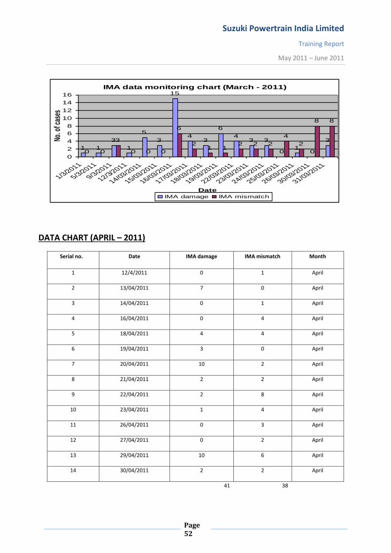
Suzuki Powertrain India Limited
Training Report
May 2011 – June 2011
Page 52
DATA CHART (APRIL – 2011)
Serial no. Date IMA damage IMA mismatch Month
1 12/4/2011 0 1 April
2 13/04/2011 7 0 April
3 14/04/2011 0 1 April
4 16/04/2011 0 4 April
5 18/04/2011 4 4 April
6 19/04/2011 3 0 April
7 20/04/2011 10 2 April
8 21/04/2011 2 2 April
9 22/04/2011 2 8 April
10 23/04/2011 1 4 April
11 26/04/2011 0 3 April
12 27/04/2011 0 2 April
13 29/04/2011 10 6 April
14 30/04/2011 2 2 April
41 38
IMA data monitoring chart (March - 2011)
1 1
3
1
5
3
15
43
6
43 3
01
0
3
0 0
3
0 0 0
6
21 1
2 2 2
4
2
8 8
0
2
4
6
8
10
12
14
16
1/3/2011
5/3/2011
9/3/2011
12/3/2011
14/03/2011
15/03/2011
16/03/2011
17/03/2011
18/03/2011
19/03/2011
22/03/2011
23/03/2011
24/03/2011
25/03/2011
26/03/2011
30/03/2011
31/03/2011
Date
No. o
f cas
es
IMA damage IMA mismatch
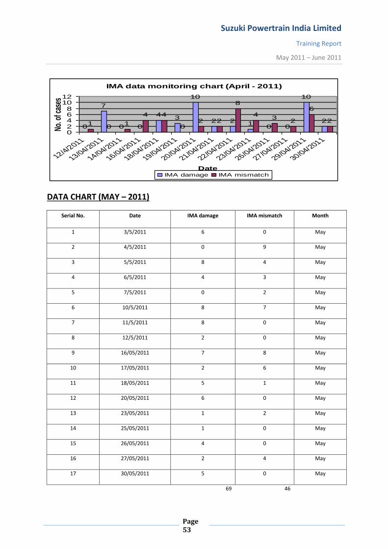
Suzuki Powertrain India Limited
Training Report
May 2011 – June 2011
Page 53
DATA CHART (MAY – 2011)
Serial No. Date IMA damage IMA mismatch Month
1 3/5/2011 6 0 May
2 4/5/2011 0 9 May
3 5/5/2011 8 4 May
4 6/5/2011 4 3 May
5 7/5/2011 0 2 May
6 10/5/2011 8 7 May
7 11/5/2011 8 0 May
8 12/5/2011 2 0 May
9 16/05/2011 7 8 May
10 17/05/2011 2 6 May
11 18/05/2011 5 1 May
12 20/05/2011 6 0 May
13 23/05/2011 1 2 May
14 25/05/2011 1 0 May
15 26/05/2011 4 0 May
16 27/05/2011 2 4 May
17 30/05/2011 5 0 May
69 46
IMA data monitoring chart (April - 2011)
0
7
0 0
43
10
2 2 10 0
10
210
1
4 4
02 2
8
43
2
6
2
02468
1012
12/4/2011
13/04/2011
14/04/2011
16/04/2011
18/04/2011
19/04/2011
20/04/2011
21/04/2011
22/04/2011
23/04/2011
26/04/2011
27/04/2011
29/04/2011
30/04/2011
Date
No.
of c
ases
IMA damage IMA mismatch

Suzuki Powertrain India Limited
Training Report
May 2011 – June 2011
Page 54
DATA CHART (JUNE – 2011)
Serial no. Date IMA damage IMA mismatch Month
1 1/6/2011 4 0 June
2 2/6/2011 2 10 June
3 3/6/2011 3 1 June
4 7/6/2011 5 6 June
5 8/6/2011 6 7 June
6 9/6/2011 2 3 June
7 10/6/2011 2 3 June
24 30
IMA data monitoring chart (May - 2011)
6
0
8
4
0
8 8
2
7
2
56
1 1
4
2
5
0
9
43
2
7
0 0
8
6
10
2
0 0
4
00123456789
10
3/5/2011
5/5/2011
7/5/2011
11/5/2011
16/05/2011
18/05/2011
23/05/2011
26/05/2011
30/05/2011
Date
No. o
f cas
es
IMA damage IMA mismatch
IMA data monitoring chart
42
35
6
2 200
10
1
67
3 3
002468
1012
1/6/2
011
2/6/2
011
3/6/2
011
7/6/2
011
8/6/2
011
9/6/2
011
10/6/
2011
13/6/
2011
Date
No.
of c
ases
IMA damage IMA mismatch

Suzuki Powertrain India Limited
Training Report
May 2011 – June 2011
Page 55
MONTH WISE ANALYSIS
IMA damage
57.7
51.9
60
44.4
March April May June
IMA mismatches
42.3
48.1
40
55.6
March April May June
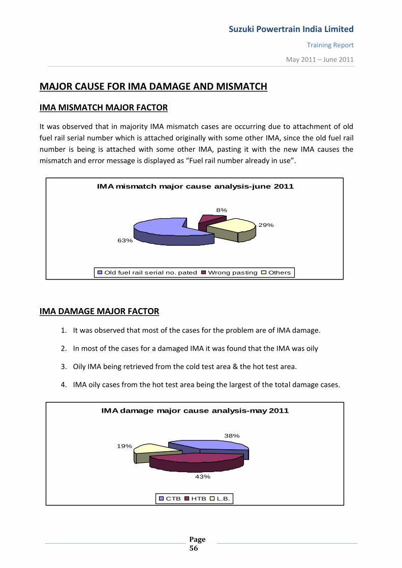
Suzuki Powertrain India Limited
Training Report
May 2011 – June 2011
Page 56
MAJOR CAUSE FOR IMA DAMAGE AND MISMATCH
IMA MISMATCH MAJOR FACTOR
It was observed that in majority IMA mismatch cases are occurring due to attachment of old
fuel rail serial number which is attached originally with some other IMA, since the old fuel rail
number is being is attached with some other IMA, pasting it with the new IMA causes the
mismatch and error message is displayed as “Fuel rail number already in use”.
IMA DAMAGE MAJOR FACTOR
1. It was observed that most of the cases for the problem are of IMA damage.
2. In most of the cases for a damaged IMA it was found that the IMA was oily
3. Oily IMA being retrieved from the cold test area & the hot test area.
4. IMA oily cases from the hot test area being the largest of the total damage cases.
IMA mismatch major cause analysis-june 2011
63%
8%
29%
Old fuel rail serial no. pated Wrong pasting Others
IMA damage major cause analysis-may 2011
38%
43%
19%
CTB HTB L.B.

Suzuki Powertrain India Limited
Training Report
May 2011 – June 2011
Page 57
SUGGESTIONS
1. Operator should be very attentive while performing his job.
2. Work should be divided among different operators as far as possible.
3. There should be system locking in such a way that the system generates only one type of
fuel rail serial no. for a particular IMA code and not different fuel rail serial no. for the
same IMA code on scanning it more than once.
4. Reloaded engine should be assembled with the same fuel rail.
5. Check sheet can be prepared for the barcode pasting operator to continuously monitor
their gloves condition.
6. Certain parameters such as labeling of the IMA code for its protection can be automatic.
7. Proper training should be provided to the new assigned operator
8. Operator should be provided with some non-sticky material gloves so that damage may
not occur due to application of grease ,oil, dirt etc. by the operator
9. IMA code label should be positioned properly.
10. Timely check of the scanners, cameras, detectors etc. to ensure no malfunction has
taken place.
Suzuki Powertrain India Limited
Training Report
May 2011 – June 2011
Page 58
CONCLUSION:-
The engine production services play a vital role in the entire assembly process, it imparts an
extensive support for the timely production of such a large quantity engines everyday and it
looks after a number of factors of production and hence its importance can be compared to
none when the question of implementing and executing the process comes.
Automobile industry thus has a huge role to play not only in the state of providing connectivity
to different regions but as well as blossoming India’s economy. They are the major
contributors in Indian economy and hence continuous efforts are being made for their
advancement in the near future.
Finally, summing it up I consider myself fortunate to be a part of India’s tycoon company for
Engine Production, though for a short tenure only. I had a great exposure to the automobile
engine production during my training as it continuously facilitated me developing my
knowledge to the where-about of automobile industry.