trainee’s booklet cfm engines a340-313 mmel … · a340-313 cfm engines - ecam warnings / mmel...
TRANSCRIPT
mmel_TOC-A340.fm
TRAINEE’S BOOKLET
MMEL EXTRACTSA340-313
CFM Engines
- ECAM WARNINGS / MMEL ENTRY
• Air conditioning .......................................................................00-21E• Auto Flight ..............................................................................00-22E• Landing gear...........................................................................00-32E• Navigation...............................................................................00-34E• APU ........................................................................................00-49E• Engine ....................................................................................00-70E
- MMEL PRESENTATION
- MMEL
• Air conditioning .......................................................................01-21• Auto flight................................................................................01-22• Navigation...............................................................................01-34• APU ........................................................................................01-49• Exhaust...................................................................................01-78• Starting ...................................................................................01-80
- OPERATIONAL PROCEDURES
• Air conditioning .......................................................................02-21• Auto flight................................................................................02-22• Exhaust...................................................................................02-78• Starting ...................................................................................02-80
Issue 03 MAY 2007

mmel_TOC-A340.fm
TRAINEE’S BOOKLET
MMEL EXTRACTSA340-313
CFM Engines
PAGE LEFT INTENTIONALLY BLANK
Issue 00 FEB 2005
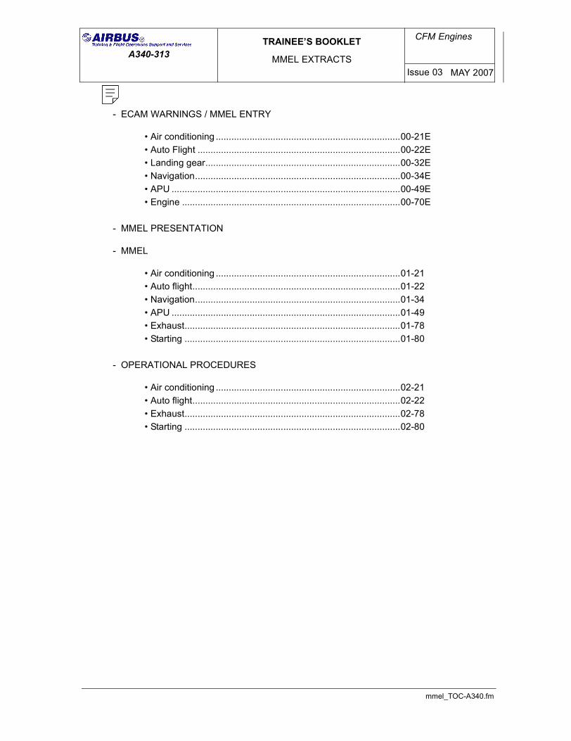
ECAM WARNINGS / MMEL ENTRY
AIR CONDITIONING
00-21E P 1
REV 16SEQ 001
AIR
HOT AIR SYS 1 (2) FAULT Refer to MMEL 21-63-03PACK 1+2 FAULT Refer to MMEL 21-52-01PACK 1 (2) OFF Refer to MMEL 21-52-01PACK 1 (2) OVHT Refer to MMEL 21-52-01PACK 1 (2) REGUL FAULT Refer to MMEL 21-52, or
Refer to MMEL 21-53PACK VALVE 1 (2) FAULT Refer to MMEL 21-51-01, or If the valve is inoperative open.
Refer to MMEL 21-52-01 If the valve is inoperative closed.
CAB PR
EXCESS CAB ALT Not applicableFWD (AFT) OFV NOT OPEN NO DISPATCHLDG ELEV FAULT Refer to MMEL 21-31-05LO DIFF PR Not applicableSAFETY VALVE OPEN Refer to MMEL 21-31-04SYS 1 (2) (1+2) FAULT Refer to MMEL 21-31-01
COND
AFT CRG ISOL FAULT (If Installed) Refer to MMEL 21-28-03-B)AFT CRG VENT FAULT (If Installed) Refer to MMEL 21-28-03-A)BULK CRG DUCT OVHT (If Installed) Refer to MMEL 21-43-02BULK CRG HEAT FAULT (If Installed) Refer to MMEL 21-43-02BULK CRG ISOL FAULT (If Installed) Refer to MMEL 21-28-04-B)BULK CRG VENT FAULT (If Installed) Refer to MMEL 21-28-04-A)CAB REST ISOL FAULT (If Installed) Refer to MMEL 21-21-04-B), or
Refer to MMEL 21-21-06DUCT OVHT Refer to MMEL 21-63-03 or
Refer to MMEL 21-43-01FWD CRG COOL FAULT (If Installed) Refer to MMEL 21-28-02-D)FWD CRG HEAT FAULT (If Installed) Refer to MMEL 21-43-01FWD CRG ISOL FAULT (If Installed) Refer to MMEL 21-28-02-B)FWD CRG VENT FAULT (If Installed) Refer to MMEL 21-28-02-A)
ECAM WARNING DISPATCH CONDITION REMARK
R
RRRR
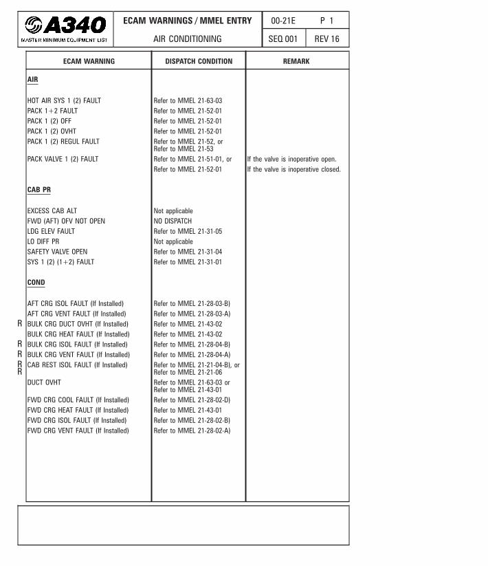
ECAM WARNINGS / MMEL ENTRY
AUTO FLIGHT
00-22E P 1
REV 18SEQ 001
AUTO FLT
AP OFF Refer to MMEL 22-10-01A/THR ENG 1(2)(3)(4) OFF Refer to MMEL 22-30-01A/THR LIMITED Not applicableA/THR OFF Refer to MMEL 22-30-01FCU FAULT NO DISPATCHFM 1 (2) FAULT Refer to MMEL 22-72-01FM 1+2 FAULT NO DISPATCHREAC W/S DET FAULT Refer to MMEL 22-60-02-B)
ECAM WARNING DISPATCH CONDITION REMARK
R
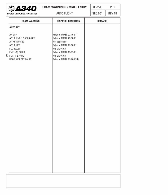
ECAM WARNINGS / MMEL ENTRY
LANDING GEAR
00-32E P 1
REV 18SEQ 001
BRAKES
A/SKID NWS OFF Not applicableANTI SKID FAULT NO DISPATCHAUTO BRK FAULT Refer to MMEL 32-42-02, or
Refer to MMEL 32-42-04HOT NO DISPATCHPARK BRK LO PR Apply ECAM procedureRELEASED Refer to MMEL 32-42-01, or
Refer to MMEL 32-42-05RESIDUAL BRAKING Refer to MMEL 32-42-01SYS 1 (2) FAULT Refer to MMEL 32-42-03
CONFIG
PARK BRK ON NO DISPATCH
L/G
DOORS NOT CLOSED NO DISPATCHGEAR NOT DOWN Not applicableGEAR NOT DOWNLOCKED Not applicableGEAR NOT UPLOCKED Not applicableGEAR UPLOCK FAULT Refer to MMEL 32-31-03LGCIU 1 FAULT NO DISPATCHLGCIU 2 FAULT Refer to MMEL 32-31-01LGCIU 1+2 FAULT NO DISPATCHL (R) LENGTHENING FAULT NO DISPATCHRETRACTION FAULT Refer to MMEL 32-31-03SYS DISAGREE NO DISPATCH
ECAM WARNING DISPATCH CONDITION REMARK
RRR
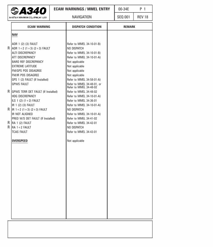
ECAM WARNINGS / MMEL ENTRY
NAVIGATION
00-34E P 1
REV 18SEQ 001
NAV
ADR 1 (2) (3) FAULT Refer to MMEL 34-10-01-B)ADR 1+2 (1+3) (2+3) FAULT NO DISPATCHALTI DISCREPANCY Refer to MMEL 34-10-01-B)ATT DISCREPANCY Refer to MMEL 34-10-01-A)BARO REF DISCREPANCY Not applicableEXTREME LATITUDE Not applicableFM/GPS POS DISAGREE Not applicableFM/IR POS DISAGREE Not applicableGPS 1 (2) FAULT (If Installed) Refer to MMEL 34-58-01-A)GPWS FAULT Refer to MMEL 34-48-01, or
Refer to MMEL 34-48-02GPWS TERR DET FAULT (If Installed) Refer to MMEL 34-48-02HDG DISCREPANCY Refer to MMEL 34-10-01-A)ILS 1 (2) (1+2) FAULT Refer to MMEL 34-36-01IR 1 (2) (3) FAULT Refer to MMEL 34-10-01-A)IR 1+2 (1+3) (2+3) FAULT NO DISPATCHIR NOT ALIGNED Refer to MMEL 34-10-01-A)PRED W/S DET FAULT (If Installed) Refer to MMEL 34-41-02RA 1 (2) FAULT Refer to MMEL 34-42-01RA 1+2 FAULT NO DISPATCHTCAS FAULT Refer to MMEL 34-43-01
OVERSPEED Not applicable
ECAM WARNING DISPATCH CONDITION REMARK
R
R
R
RR
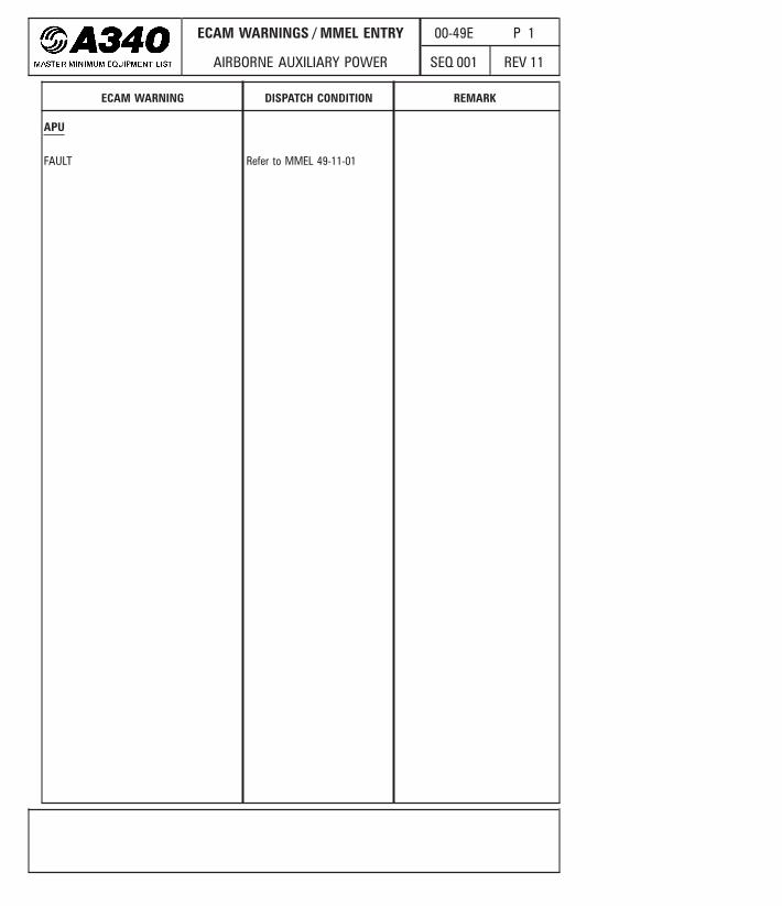
ECAM WARNINGS / MMEL ENTRY
AIRBORNE AUXILIARY POWER
00-49E P 1
REV 11SEQ 001
APU
FAULT Refer to MMEL 49-11-01
ECAM WARNING DISPATCH CONDITION REMARK
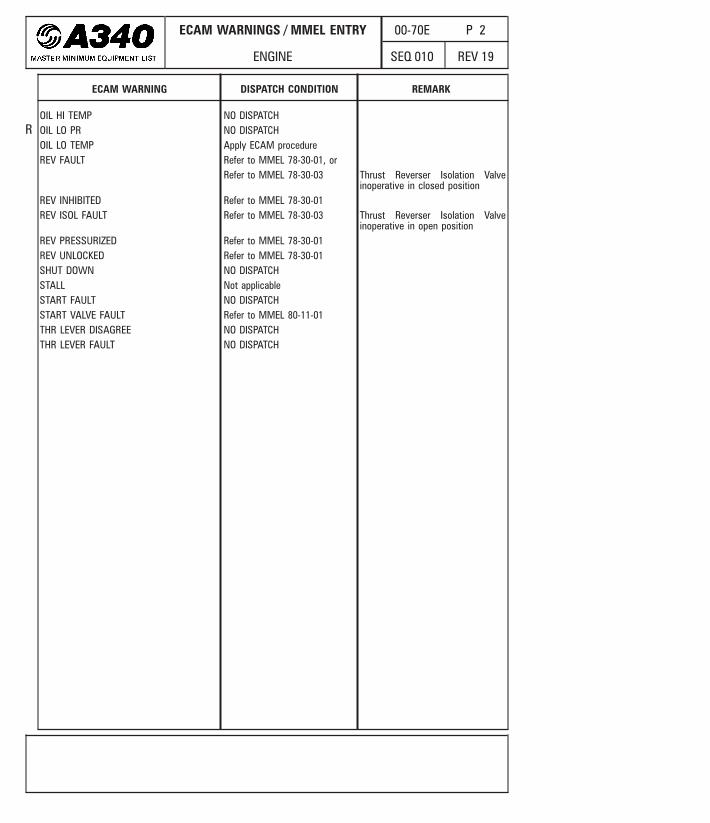
ECAM WARNINGS / MMEL ENTRY
ENGINE
00-70E P 2
REV 19SEQ 010
OIL HI TEMP NO DISPATCHOIL LO PR NO DISPATCHOIL LO TEMP Apply ECAM procedureREV FAULT Refer to MMEL 78-30-01, or
Refer to MMEL 78-30-03 Thrust Reverser Isolation Valveinoperative in closed position
REV INHIBITED Refer to MMEL 78-30-01REV ISOL FAULT Refer to MMEL 78-30-03 Thrust Reverser Isolation Valve
inoperative in open positionREV PRESSURIZED Refer to MMEL 78-30-01REV UNLOCKED Refer to MMEL 78-30-01SHUT DOWN NO DISPATCHSTALL Not applicableSTART FAULT NO DISPATCHSTART VALVE FAULT Refer to MMEL 80-11-01THR LEVER DISAGREE NO DISPATCHTHR LEVER FAULT NO DISPATCH
ECAM WARNING DISPATCH CONDITION REMARK
R
CFM Eng. : All

MASTER MINIMUM EQUIPMENT LIST
MMEL PRESENTATION
01-00 P 1
REV 12SEQ 001
GENERAL
A “R” in the margin indicates a change, addition or deletion in the adjacent text for thecurrent revision of that page only. The “R” is dropped at the next revision of that page.
COLUMN 1 : “ITEM”
It lists the equipment, components, systems or functions, for which dispatch conditionsapply.System numbers are based on Air Transport Association (ATA) specification number 100.“(If Installed)” in the ITEM column indicates that the listed item is not applicable to allmodels or configurations. This does not imply that the airplane may be operated, inaccordance with the MMEL, with the item removed.
Note : One single computer may include several functions. The corresponding MMELentry is either the computer itself if fully inoperative or each function separately.If several functions are inoperative, reference must be made to each one.
COLUMN 2 : “RECTIFICATION INTERVAL”
It indicates, for a given item, the rectification interval category. The category of each itemis determined according to the requirements specified below:
Category ANo standard interval is specified, however, items in this category shall be rectified inaccordance with the conditions stated in the REMARKS OR EXCEPTIONS column 5 of theMMEL.Where a time period is specified it shall start at 00:01 on the calendar day following theday of discovery.
Category BItems in this category shall be rectified within three (3) consecutive calendar days,excluding the day of discovery.For example, if it were recorded at 10 a.m. on January 26th, the three day interval wouldbegin at midnight the 26th and end at midnight the 29th.
R
R
R
RR
RRRRRR
RRRRR
MASTER MINIMUM EQUIPMENT LIST
MMEL PRESENTATION
01-00 P 2
REV 17SEQ 001
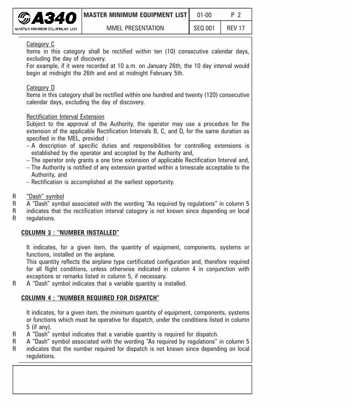
Category CItems in this category shall be rectified within ten (10) consecutive calendar days,excluding the day of discovery.For example, if it were recorded at 10 a.m. on January 26th, the 10 day interval wouldbegin at midnight the 26th and end at midnight February 5th.
Category DItems in this category shall be rectified within one hundred and twenty (120) consecutivecalendar days, excluding the day of discovery.
Rectification Interval ExtensionSubject to the approval of the Authority, the operator may use a procedure for theextension of the applicable Rectification Intervals B, C, and D, for the same duration asspecified in the MEL, provided :– A description of specific duties and responsibilities for controlling extensions is
established by the operator and accepted by the Authority and,– The operator only grants a one time extension of applicable Rectification Interval and,– The Authority is notified of any extension granted within a timescale acceptable to the
Authority, and– Rectification is accomplished at the earliest opportunity.
“Dash” symbolA “Dash” symbol associated with the wording “As required by regulations” in column 5indicates that the rectification interval category is not known since depending on localregulations.
COLUMN 3 : “NUMBER INSTALLED”
It indicates, for a given item, the quantity of equipment, components, systems orfunctions, installed on the airplane.This quantity reflects the airplane type certificated configuration and, therefore requiredfor all flight conditions, unless otherwise indicated in column 4 in conjunction withexceptions or remarks listed in column 5, if necessary.A “Dash” symbol indicates that a variable quantity is installed.
COLUMN 4 : “NUMBER REQUIRED FOR DISPATCH”
It indicates, for a given item, the minimum quantity of equipment, components, systemsor functions which must be operative for dispatch, under the conditions listed in column5 (if any).A “Dash” symbol indicates that a variable quantity is required for dispatch.A “Dash” symbol associated with the wording “As required by regulations” in column 5indicates that the number required for dispatch is not known since depending on localregulations.
RRRR
R
RRR

MASTER MINIMUM EQUIPMENT LIST
MMEL PRESENTATION
01-00 P 3
REV 19SEQ 001
COLUMN 5 : “REMARKS OR EXCEPTIONS”
Asterisk* Asterisk or a placarding action within the dispatch condition requires inoperativeequipment, component, system or function to be placarded in the cockpit to informcrewmembers of the equipment condition. Unless otherwise specified herein, placardwording and location will be determined by the operator.The operator should determine the personnel (maintenance and/or flight crew) authorizedto placard items.
Operational procedure(o) Symbol indicates a requirement for a specific operational procedure which must beaccomplished when operating with the listed item inoperative.Purpose of the operational procedure might be :– to require the flight crew to perform action(s),– to provide limitations or performance penalties,– to provide useful information to the crew.The operational procedure must be applied, before each flight, unless a periodicity isclearly specified in the REMARKS OR EXCEPTIONS column of the MMEL. When aperiodicity is defined, the operational procedure must be applied before the first flightunder the relevant MMEL item and must be repeated at the defined interval.In all cases, the operational procedure must be known by the flight crew before eachflight. The aircraft in MMEL condition should be considered (including the (o) procedure)according to the flight phase.
Maintenance procedure(m) Symbol indicates a requirement for a specific maintenance procedure which must beaccomplished when operating with the listed item inoperative.If no periodicity is defined in the REMARKS OR EXCEPTIONS column of the MMELmaintenance action is a one time action to be accomplished before the first flight underrelevant MMEL item (e.g. a deactivation procedure).Otherwise, this is a repetitive action. In this case, periodicity of the maintenanceprocedure is defined in the REMARKS OR EXCEPTIONS column of the relevant MMELitem.When a periodicity is defined, maintenance procedure must be applied before the firstflight under the relevant MMEL item and must be repeated at the defined interval.Normally these procedures are accomplished by maintenance personnel : however, ifapproved by national autorities, other personnel may be qualified and authorized toperform certain actions. Procedures requiring specialized knowledge or skill, or requiringthe use of tools or test equipment should be accomplished by maintenance personnel.
RR
R
R
R
RR
RRRRRRRRRRRRR
RR
MASTER MINIMUM EQUIPMENT LIST
MMEL PRESENTATION
01-00 P 4
REV 19SEQ 001
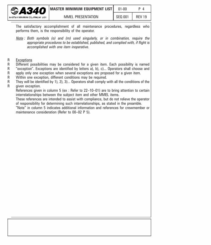
The satisfactory accomplishment of all maintenance procedures, regardless whoperforms them, is the responsibility of the operator.
Note : Both symbols (o) and (m) used singularly, or in combination, require theappropriate procedures to be established, published, and complied with, if flight isaccomplished with one item inoperative.
ExceptionsDifferent possibilities may be considered for a given item. Each possibility is named“exception”. Exceptions are identified by letters a), b), c)... Operators shall choose andapply only one exception when several exceptions are proposed for a given item.Within one exception, different conditions may be required.They will be identified by 1), 2), 3)... Operators shall comply with all the conditions of thegiven exception.References given in column 5 (ex : Refer to 22–10–01) are to bring attention to certaininterrelationships between the subject item and other MMEL items.These references are intended to assist with compliance, but do not relieve the operatorof responsibility for determining such interrelationships, as stated in the preamble.”Note” in column 5 indicates additional information and references for crewmember ormaintenance consideration (Refer to 00–02 P 5).
RRRRRRR
MASTER MINIMUM EQUIPMENT LIST
MMEL PRESENTATION
01-00 P 5
REV 19SEQ 001
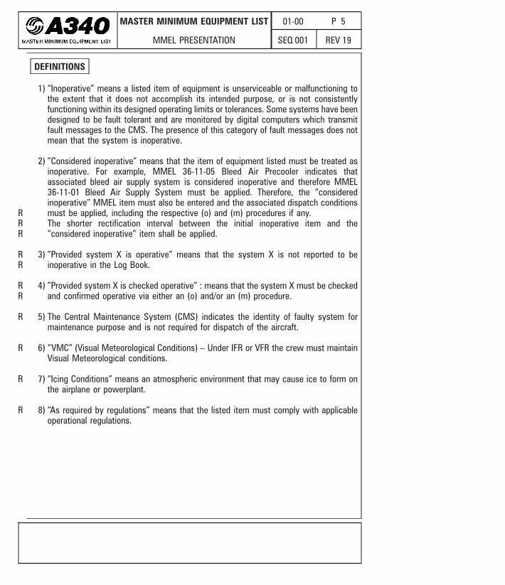
DEFINITIONS
1) “Inoperative” means a listed item of equipment is unserviceable or malfunctioning tothe extent that it does not accomplish its intended purpose, or is not consistentlyfunctioning within its designed operating limits or tolerances. Some systems have beendesigned to be fault tolerant and are monitored by digital computers which transmitfault messages to the CMS. The presence of this category of fault messages does notmean that the system is inoperative.
2) ”Considered inoperative” means that the item of equipment listed must be treated asinoperative. For example, MMEL 36-11-05 Bleed Air Precooler indicates thatassociated bleed air supply system is considered inoperative and therefore MMEL36-11-01 Bleed Air Supply System must be applied. Therefore, the “consideredinoperative” MMEL item must also be entered and the associated dispatch conditionsmust be applied, including the respective (o) and (m) procedures if any.The shorter rectification interval between the initial inoperative item and the“considered inoperative” item shall be applied.
3) ”Provided system X is operative” means that the system X is not reported to beinoperative in the Log Book.
4) ”Provided system X is checked operative” : means that the system X must be checkedand confirmed operative via either an (o) and/or an (m) procedure.
5) The Central Maintenance System (CMS) indicates the identity of faulty system formaintenance purpose and is not required for dispatch of the aircraft.
6) “VMC” (Visual Meteorological Conditions) – Under IFR or VFR the crew must maintainVisual Meteorological conditions.
7) “Icing Conditions” means an atmospheric environment that may cause ice to form onthe airplane or powerplant.
8) “As required by regulations” means that the listed item must comply with applicableoperational regulations.
R
R
R
R
R
RR
RR
RR

MASTER MINIMUM EQUIPMENT LIST
AIR CONDITIONING
01-21 P 11
REV 18SEQ 001
28-04 BULK CargoCompartmentVentilation(If Installed)
A) Extraction Fan D 1 0 (o) 2
B) Isolation Valve D 2 0 (o)(m) a) One or both may be inoperativeprovided both valves are checkedclosed.
- or -
3
C 2 0 b) One or both may be inoperativein open position provided theassociated cargo compartment isemptyordoesnotcontain inflammableor combustible materials.
3
C) ISOL VALVES Pb Sw
a) FAULT Light D 1 0 * 4
b) OFF Light D 1 0 * 2
21-31 PRESSURE CONTROLAND MONITORING
NOTEThe whole pressurization systemmay be inoperative for anon-pressurized flight. Refer to FCOM2.04.20.
31-01 Automatic CabinPressure ControlSystem (CPC, outflowvalve AUTO channels)
C 2 1 (o) One may be inoperative providedcabin pressure indications on ECAMCAB PRESS page are operative inmanual mode.
4REF GQ 211-507/10/92ESD-009/01
1 . SYSTEM AND SEQUENCE NUMBERS
ITEM
2 . RECTIFICATION INTERVAL3 . NUMBER INSTALLED
4 . NUMBER REQUIRED FOR DISPATCH5 . REMARKS OR EXCEPTIONS
RRRR
MASTER MINIMUM EQUIPMENT LIST
AIR CONDITIONING
01-21 P 12
REV 19SEQ 001
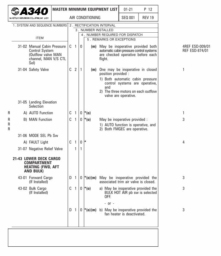
31-02 Manual Cabin PressureControl System(Outflow valve MANchannel, MAN V/S CTLSel)
C 1 0 (m) May be inoperative provided bothautomatic cabin pressure control systemsare checked operative before eachflight.
4REF ESD-009/01REF ESD-874/01
31-04 Safety Valve C 2 1 (m) One may be inoperative in closedposition provided :1) Both automatic cabin pressure
control systems are operative,and
2) The three motors on each outflowvalve are operative.
1
31-05 Landing ElevationSelection
A) AUTO Function C 1 0 *(o) 1
B) MAN Function C 1 0 *(o) May be inoperative provided :1) AUTO function is operative, and2) Both FMGEC are operative.
3
31-06 MODE SEL Pb Sw
A) FAULT Light C 1 0 * 4
31-07 Negative Relief Valve 1 1
21-43 LOWER DECK CARGOCOMPARTMENTHEATING (FWD, AFTAND BULK)
43-01 Forward Cargo(If Installed)
D 1 0 *(o)(m) May be inoperative provided theassociated trim air valve is closed.
3
43-02 Bulk Cargo(If Installed)
C 1 0 *(o) a) May be inoperative provided theBULK HOT AIR pb sw is selectedOFF.
- or -
3
D 1 0 *(o)(m) b) May be inoperative provided thefan heater is deactivated.
3
1 . SYSTEM AND SEQUENCE NUMBERS
ITEM
2 . RECTIFICATION INTERVAL3 . NUMBER INSTALLED
4 . NUMBER REQUIRED FOR DISPATCH5 . REMARKS OR EXCEPTIONS
R
RRR
MASTER MINIMUM EQUIPMENT LIST
AUTO FLIGHT
01-22 P 1
REV 19SEQ 001
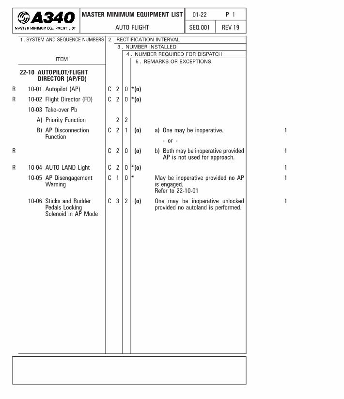
22-10 AUTOPILOT/FLIGHTDIRECTOR (AP/FD)
10-01 Autopilot (AP) C 2 0 *(o)
10-02 Flight Director (FD) C 2 0 *(o)
10-03 Take-over Pb
A) Priority Function 2 2
B) AP DisconnectionFunction
C 2 1 (o) a) One may be inoperative.
- or -
1
C 2 0 (o) b) Both may be inoperative providedAP is not used for approach.
1
10-04 AUTO LAND Light C 2 0 *(o) 1
10-05 AP DisengagementWarning
C 1 0 * May be inoperative provided no APis engaged.Refer to 22-10-01
1
10-06 Sticks and RudderPedals LockingSolenoid in AP Mode
C 3 2 (o) One may be inoperative unlockedprovided no autoland is performed.
1
1 . SYSTEM AND SEQUENCE NUMBERS
ITEM
2 . RECTIFICATION INTERVAL3 . NUMBER INSTALLED
4 . NUMBER REQUIRED FOR DISPATCH5 . REMARKS OR EXCEPTIONS
R
R
R
R

MASTER MINIMUM EQUIPMENT LIST
AUTO FLIGHT
01-22 P 2
REV 18SEQ 001
22-30 AUTOTHRUST
30-01 Autothrust Function C 1 1 * a) May be inoperative on one engine.
- or -
3
C 1 0 *(o)(m) b) May be inoperative provided allthrust lever position sensors arechecked operative.
1
30-02 Autothrust InstinctiveDisconnect Pb
C 2 1 (m) One may be inoperative provided allother autothrust disconnection meansare operative.
1
30-03 AutothrustDisengagementWarning
C 1 0 (o) May be inoperative provided theautothrust is considered inoperative.
1
22-60 FLIGHT ENVELOPE (FE)
60-01 Characteristic Speeds Refer to 34-13-01-C)
60-02 Windshear DetectionSystem
A) Predictive(If Installed)
− 2 − As required by regulations
B) Reactive − 2 − As required by regulations
Note : If required, it is not allowedto replace it by the predictive windsheardetection system (If Installed).
60-03 Warning and Cautionon ECAM E/WD
A) FUEL EXCESS AFT CG Refer to 28-40-17-A)
1 . SYSTEM AND SEQUENCE NUMBERS
ITEM
2 . RECTIFICATION INTERVAL3 . NUMBER INSTALLED
4 . NUMBER REQUIRED FOR DISPATCH5 . REMARKS OR EXCEPTIONS
R
R
MASTER MINIMUM EQUIPMENT LIST
AUTO FLIGHT
01-22 P 3
REV 19SEQ 001
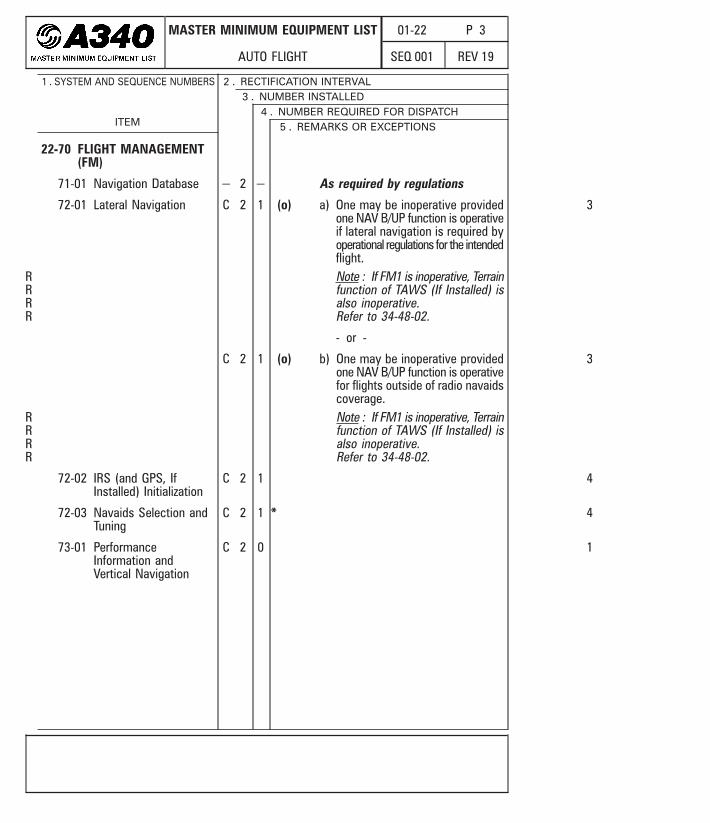
22-70 FLIGHT MANAGEMENT(FM)
71-01 Navigation Database − 2 − As required by regulations
72-01 Lateral Navigation C 2 1 (o) a) One may be inoperative providedone NAV B/UP function is operativeif lateral navigation is required byoperational regulations for the intendedflight.Note : If FM1 is inoperative, Terrainfunction of TAWS (If Installed) isalso inoperative.Refer to 34-48-02.
- or -
3
C 2 1 (o) b) One may be inoperative providedone NAV B/UP function is operativefor flights outside of radio navaidscoverage.Note : If FM1 is inoperative, Terrainfunction of TAWS (If Installed) isalso inoperative.Refer to 34-48-02.
3
72-02 IRS (and GPS, IfInstalled) Initialization
C 2 1 4
72-03 Navaids Selection andTuning
C 2 1 * 4
73-01 PerformanceInformation andVertical Navigation
C 2 0 1
1 . SYSTEM AND SEQUENCE NUMBERS
ITEM
2 . RECTIFICATION INTERVAL3 . NUMBER INSTALLED
4 . NUMBER REQUIRED FOR DISPATCH5 . REMARKS OR EXCEPTIONS
RRRR
RRRR
STD or Mod : (53919 + 54273)

MASTER MINIMUM EQUIPMENT LIST
AUTO FLIGHT
01-22 P 8
REV 19SEQ 001
83-01 Flight ManagementGuidance and EnvelopeComputer (FMGEC)
C 2 1 (m) Refer to 22-10-01, andRefer to 22-10-02, andRefer to 22-72-01
4
83-02 FMA Indications onPFD
A) AP/FD RelatedIndications
C − − a) One or more may be inoperativeon one FMA.
- or -
1
C − − (o) b) One or more may be inoperativeon both FMA’s provided AP/FD isnot used.
1
B) A/THR RelatedIndications
C − − a) One or more may be inoperativeon one FMA.
- or -
1
C − − *(o) b) One or more may be inoperativeonbothFMA’sprovided theautothrustis considered inoperative.
1
C) Approach and LandingCapabilities
C − − (o) One or more may be inoperative onone or both FMA’s.
3
D) Special Messages C − 8 The following messages are requiredon both sides :– MAN PITCH TRIM ONLY– USE MAN PITCH TRIM– EFIS SINGLE SOURCE 1– EFIS SINGLE SOURCE 2Note : Above message(s) can onlyappear in case of failure orreconfiguration.
2
1 . SYSTEM AND SEQUENCE NUMBERS
ITEM
2 . RECTIFICATION INTERVAL3 . NUMBER INSTALLED
4 . NUMBER REQUIRED FOR DISPATCH5 . REMARKS OR EXCEPTIONS
R
R
R

MASTER MINIMUM EQUIPMENT LIST
NAVIGATION
01-34 P 1
REV 19SEQ 001
34-10 AIR DATA/INERTIALREFERENCE SYSTEM(ADIRS)
10-01 ADIRS
A) IR C 3 2 (o)(m) One may be inoperative provided thefollowing checks are made beforeeach flight :1) Both flight controls Nz accelerometers
are operative, and2) Both flight controls Rate Gyros
are operative.Note : If IR 1 is inoperative and ifTCAS is affected, Refer to 34-43-01.If IR 1 is inoperative, Terrain functionof TAWS (If Installed) is also inoperative.Refer to 34-48-02.
4REF SQIP 466.321/92
B) ADR C 3 2 (o) Note : If ADR1 is inoperative, theGPWS or TAWS is inoperative.Refer to 34-48-01, orRefer to 34-48-02.
4REF SQIP 466.321/92
10-02 ADIRS Panel
A) IR Mode Sel C 3 2 1
B) ON BAT Light C 1 0 * 1
1 . SYSTEM AND SEQUENCE NUMBERS
ITEM
2 . RECTIFICATION INTERVAL3 . NUMBER INSTALLED
4 . NUMBER REQUIRED FOR DISPATCH5 . REMARKS OR EXCEPTIONS
MASTER MINIMUM EQUIPMENT LIST
NAVIGATION
01-34 P 9
REV 19SEQ 001
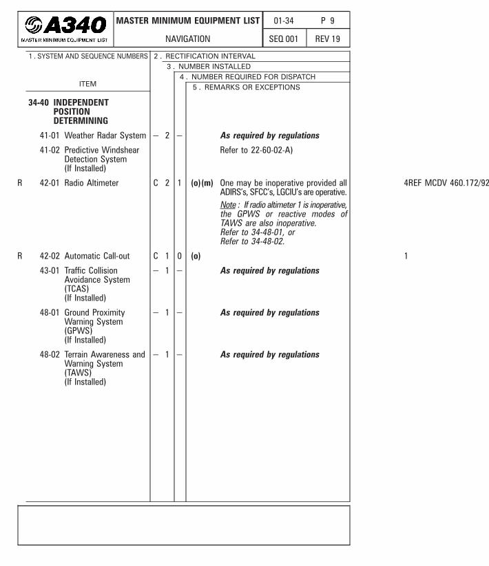
34-40 INDEPENDENTPOSITIONDETERMINING
41-01 Weather Radar System − 2 − As required by regulations
41-02 Predictive WindshearDetection System(If Installed)
Refer to 22-60-02-A)
42-01 Radio Altimeter C 2 1 (o)(m) One may be inoperative provided allADIRS’s, SFCC’s, LGCIU’s are operative.Note : If radio altimeter 1 is inoperative,the GPWS or reactive modes ofTAWS are also inoperative.Refer to 34-48-01, orRefer to 34-48-02.
4REF MCDV 460.172/92
42-02 Automatic Call-out C 1 0 (o) 1
43-01 Traffic CollisionAvoidance System(TCAS)(If Installed)
− 1 − As required by regulations
48-01 Ground ProximityWarning System(GPWS)(If Installed)
− 1 − As required by regulations
48-02 Terrain Awareness andWarning System(TAWS)(If Installed)
− 1 − As required by regulations
1 . SYSTEM AND SEQUENCE NUMBERS
ITEM
2 . RECTIFICATION INTERVAL3 . NUMBER INSTALLED
4 . NUMBER REQUIRED FOR DISPATCH5 . REMARKS OR EXCEPTIONS
R
R

MASTER MINIMUM EQUIPMENT LIST
AIRBORNE AUXILIARY POWER
01-49 P 1
REV 18SEQ 001
49-10 POWER PLANT
11-01 Power Plant (APU) C 1 0 *(o) a) May be inoperative.
- or -
3
D 1 0 *(o)(m) b) May be inoperative provided theAPU is deactivated or removed.
3
16-01 Air Intake System
A) Air Intake Flap C 1 0 (m) a) May be inoperative in open position.
- or -
3
C 1 0 (o) b) May be inoperative provided theAPU is not used.
3
49-30 ENGINE FUEL ANDCONTROL
30-01 Aft APU Fuel Pump C 1 0 a) May be inoperative provided :1) The forward APU fuel pump is
operative, and2) The APU is considered inoperative
in flight above FL 255.
- or -
3
C 1 0 (o) b) May be inoperative provided theAPU is not used.
3
1 . SYSTEM AND SEQUENCE NUMBERS
ITEM
2 . RECTIFICATION INTERVAL3 . NUMBER INSTALLED
4 . NUMBER REQUIRED FOR DISPATCH5 . REMARKS OR EXCEPTIONS
R
R
R
R
RR
RRRRR
RR

MASTER MINIMUM EQUIPMENT LIST
EXHAUST
01-78 P 1
REV 19SEQ 010
78-30 THRUST REVERSER
30-01 Thrust Reverser C 4 0 *(o)(m) a) One or more may be inoperativeprovided :1) The inoperative thrust reverser
is deactivated and secured inthe stowed position, and
2) TheENG1(2)(3)(4) REV INHIBITEDcaution is displayed on ECAME/WD after deactivation, and
3) The ENG 1(2)(3)(4) REVUNLOCKED caution associatedwith the inoperative thrust reverseris not displayed on ECAME/WD after deactivation, and
4) Appropriate performanceadjustments are applied.
- or -
3
THIS ITEM CONTINUES ON NEXTPAGE
1 . SYSTEM AND SEQUENCE NUMBERS
ITEM
2 . RECTIFICATION INTERVAL3 . NUMBER INSTALLED
4 . NUMBER REQUIRED FOR DISPATCH5 . REMARKS OR EXCEPTIONS
RR
CFM Eng. : All
MASTER MINIMUM EQUIPMENT LIST
EXHAUST
01-78 P 2
REV 19SEQ 010
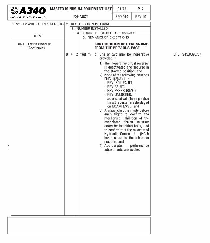
30-01 Thrust reverser(Continued)
CONTINUATION OF ITEM 78-30-01FROM THE PREVIOUS PAGE
B 4 2 *(o)(m) b) One or two may be inoperativeprovided :1) The inoperative thrust reverser
is deactivated and secured inthe stowed position, and
2) None of the following cautionsENG 1(2)(3)(4) :– REV ISOL FAULT,– REV FAULT,– REV PRESSURIZED,– REV UNLOCKED,
associated with the inoperativethrust reverser are displayedon ECAM E/WD, and
3) A visual check is made beforeeach flight to confirm themechanical inhibition of theassociated thrust reverserdoors by inhibition bolts, andto confirm that the associatedHydraulic Control Unit (HCU)lever is set to the inhibitionposition, and
4) Appropriate performanceadjustments are applied.
3REF 945.0393/04
1 . SYSTEM AND SEQUENCE NUMBERS
ITEM
2 . RECTIFICATION INTERVAL3 . NUMBER INSTALLED
4 . NUMBER REQUIRED FOR DISPATCH5 . REMARKS OR EXCEPTIONS
RR
CFM Eng. : All
MASTER MINIMUM EQUIPMENT LIST
STARTING
01-80 P 1
REV 12SEQ 001
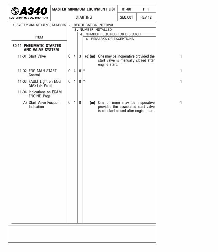
80-11 PNEUMATIC STARTERAND VALVE SYSTEM
11-01 Start Valve C 4 3 (o)(m) One may be inoperative provided thestart valve is manually closed afterengine start.
1
11-02 ENG MAN STARTControl
C 4 0 * 1
11-03 FAULT Light on ENGMASTER Panel
C 4 0 * 1
11-04 Indications on ECAMENGINE Page
A) Start Valve PositionIndication
C 4 0 (m) One or more may be inoperativeprovided the associated start valveis checked closed after engine start.
1
1 . SYSTEM AND SEQUENCE NUMBERS
ITEM
2 . RECTIFICATION INTERVAL3 . NUMBER INSTALLED
4 . NUMBER REQUIRED FOR DISPATCH5 . REMARKS OR EXCEPTIONS

OPERATIONAL PROCEDURES
AIR CONDITIONING
02-21 P 5
REV 19SEQ 200
D) Cargo Cooling System- - - - - - - - - - - - - -
Select AFT TEMP REGUL selector OFF and check that aft cargo cold air / isolationvalves indication is either open green or closed amber and check that no CONDAFT CRG ISOL FAULT caution is displayed on ECAM E/WD.If the aft cargo cold air / isolation valves indication is open amber and the CONDAFT CRG ISOL FAULT caution is displayed on ECAM E/WD, the cold air valve mustbe manually secured closed by use of the associated (m) procedure.
For livestock transportation, refer to livestock transportation manual.
28-04 BULK Cargo Compartment Ventilation (If Installed)
A) Extraction Fan- - - - - - - - -
For livestock transportation, refer to livestock transportation manual.
B) Isolation Valve- - - - - - - - -
a)Select BULK ISOL VALVES pb sw OFF and check that associated FAULT light is notilluminated. If FAULT light illuminates, the affected isolation valve must bemanually secured closed by use of the associated (m) procedure.
For livestock transportation, refer to livestock transportation manual.
21-31 PRESSURE CONTROL AND MONITORING
31-01 Automatic Cabin Pressure Control System
During cockpit preparation :
MODE SEL . . . . . . . . . . . . . . . . . . . . . . . . . . . . . . . . . . . . . . . . MANCheck on ECAM CAB PRESS page that cabin differential pressure, cabin verticalspeed, cabin altitude and outflow valves position are available.Select MAN V/S CTL selector DN and check on ECAM CAB PRESS page outflowvalves movement.MODE SEL . . . . . . . . . . . . . . . . . . . . . . . . . . . . . . . . . . . . . . . . AUTO
31-05 Landing Elevation Selection
A) AUTO Function- - - - - - - - - -
Before take off, set LDG ELEV selector at destination airport altitude.
B) MAN Function- - - - - - - - -
Check on ECAM CAB PRESS page that LDG ELEV AUTO is displayed to confirmcorrect position of the LDG ELEV selector.
R
R
R
RR
Mod : 47000 + 51974
OPERATIONAL PROCEDURES
AUTO FLIGHT
02-22 P 1
REV 19SEQ 001
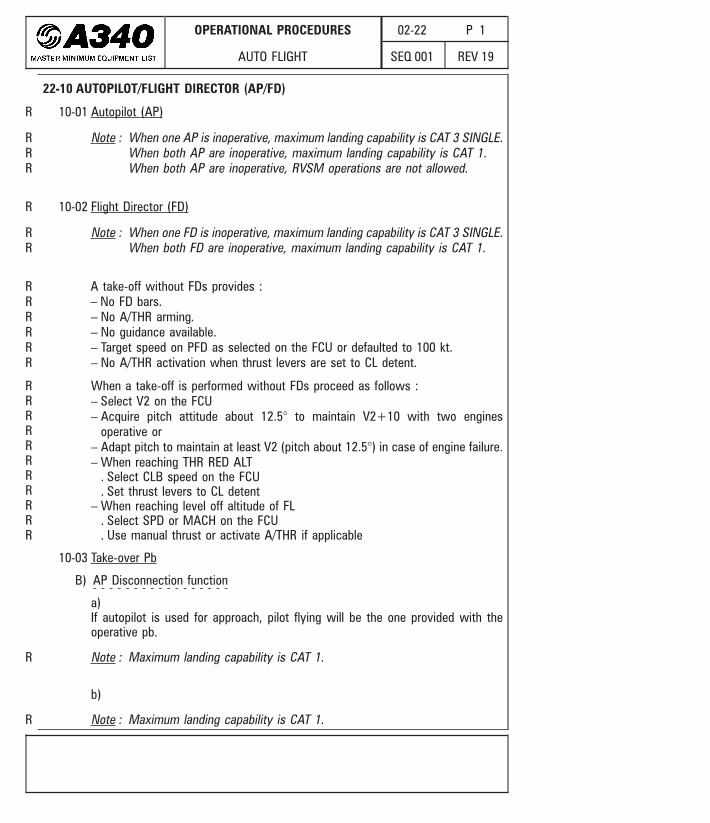
22-10 AUTOPILOT/FLIGHT DIRECTOR (AP/FD)
10-01 Autopilot (AP)
Note : When one AP is inoperative, maximum landing capability is CAT 3 SINGLE.When both AP are inoperative, maximum landing capability is CAT 1.When both AP are inoperative, RVSM operations are not allowed.
10-02 Flight Director (FD)
Note : When one FD is inoperative, maximum landing capability is CAT 3 SINGLE.When both FD are inoperative, maximum landing capability is CAT 1.
A take-off without FDs provides :– No FD bars.– No A/THR arming.– No guidance available.– Target speed on PFD as selected on the FCU or defaulted to 100 kt.– No A/THR activation when thrust levers are set to CL detent.
When a take-off is performed without FDs proceed as follows :– Select V2 on the FCU– Acquire pitch attitude about 12.5° to maintain V2+10 with two engines
operative or– Adapt pitch to maintain at least V2 (pitch about 12.5°) in case of engine failure.– When reaching THR RED ALT
. Select CLB speed on the FCU
. Set thrust levers to CL detent– When reaching level off altitude of FL
. Select SPD or MACH on the FCU
. Use manual thrust or activate A/THR if applicable
10-03 Take-over Pb
B) AP Disconnection function- - - - - - - - - - - - - - - - -
a)If autopilot is used for approach, pilot flying will be the one provided with theoperative pb.
Note : Maximum landing capability is CAT 1.
b)
Note : Maximum landing capability is CAT 1.
R
R
R
R
RRR
RR
RRRRRR
RRRRRRRRRRR
OPERATIONAL PROCEDURES
AUTO FLIGHT
02-22 P 2
REV 19SEQ 001
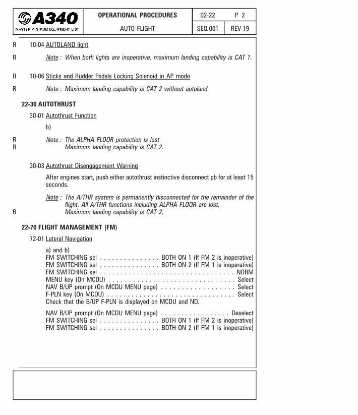
10-04 AUTOLAND light
Note : When both lights are inoperative, maximum landing capability is CAT 1.
10-06 Sticks and Rudder Pedals Locking Solenoid in AP mode
Note : Maximum landing capability is CAT 2 without autoland
22-30 AUTOTHRUST
30-01 Autothrust Function
b)
Note : The ALPHA FLOOR protection is lostMaximum landing capability is CAT 2.
30-03 Autothrust Disengagement Warning
After engines start, push either autothrust instinctive disconnect pb for at least 15seconds.
Note : The A/THR system is permanently disconnected for the remainder of theflight. All A/THR functions including ALPHA FLOOR are lost.Maximum landing capability is CAT 2.
22-70 FLIGHT MANAGEMENT (FM)
72-01 Lateral Navigation
a) and b)FM SWITCHING sel . . . . . . . . . . . . . . . BOTH ON 1 (If FM 2 is inoperative)FM SWITCHING sel . . . . . . . . . . . . . . . BOTH ON 2 (If FM 1 is inoperative)FM SWITCHING sel . . . . . . . . . . . . . . . . . . . . . . . . . . . . . . . . . NORMMENU key (On MCDU) . . . . . . . . . . . . . . . . . . . . . . . . . . . . . . . SelectNAV B/UP prompt (On MCDU MENU page) . . . . . . . . . . . . . . . . . . SelectF-PLN key (On MCDU) . . . . . . . . . . . . . . . . . . . . . . . . . . . . . . . . SelectCheck that the B/UP F-PLN is displayed on MCDU and ND.
NAV B/UP prompt (On MCDU MENU page) . . . . . . . . . . . . . . . . . DeselectFM SWITCHING sel . . . . . . . . . . . . . . . BOTH ON 1 (If FM 2 is inoperative)FM SWITCHING sel . . . . . . . . . . . . . . . BOTH ON 2 (If FM 1 is inoperative)
R
R
RR
R
R
R
OPERATIONAL PROCEDURES
AUTO FLIGHT
02-22 P 3
REV 19SEQ 001
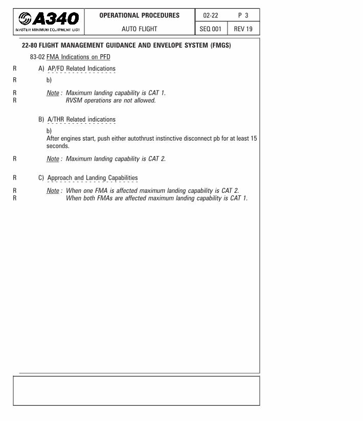
22-80 FLIGHT MANAGEMENT GUIDANCE AND ENVELOPE SYSTEM (FMGS)
83-02 FMA Indications on PFD
A) AP/FD Related Indications- - - - - - - - - - - - - - - - -
b)
Note : Maximum landing capability is CAT 1.RVSM operations are not allowed.
B) A/THR Related indications- - - - - - - - - - - - - - - - -
b)After engines start, push either autothrust instinctive disconnect pb for at least 15seconds.
Note : Maximum landing capability is CAT 2.
C) Approach and Landing Capabilities- - - - - - - - - - - - - - - - - - - - - -
Note : When one FMA is affected maximum landing capability is CAT 2.When both FMAs are affected maximum landing capability is CAT 1.
R
R
R
R
RR
RR

OPERATIONAL PROCEDURES
EXHAUST
02-78 P 5
REV 19SEQ 001
30-02 Engine 1 and 4 Thrust Lever Interlock
b)The outboard thrust reversers cannot be selected above idle reverse due to theengine 1 and 4 thrust reverser lever interlock inoperative in locked position.
FlightPreparation :PerformanceComputation
Phase Runway State Performance Adjustments
Takeoff
Dry No performance adjustments (Performance are computed basicallywithout thrust reversers)
Wet /Contaminated
Use performance data determined with either :Two Outboard Thrust Reversers inoperative,orAll Thrust Reversers inoperative
Landing
Dry / Wet No performance adjustments (Performance are computed basicallywithout thrust reversers)
Contaminated
Use performance data determined with either :Two Outboard Thrust Reversers inoperative,orAll Thrust Reversers inoperative
ThrustRerversers
Use
During thrust reversers application, select ALL thrust levers.
R

OPERATIONAL PROCEDURES
STARTING
02-80 P 1
REV 14SEQ 001
80-11 PNEUMATIC STARTER AND VALVE SYSTEM
11-01 Start Valve
Apply the START VALVE MANUAL OPERATION procedure of the FCOM (3.04.70)R
