trail - federal highway administration
TRANSCRIPT
UN
ITEDSTATES OF AMERIC
A
DE
PART
MENT OF TRANSPORTATION
UN
ITEDSTATES OF AMERIC
A
DE
PART
MENT OF TRANSPORTATION
TrailConstructionandMaintenanceNotebook2004 Edition
TrailConstructionandMaintenanceNotebook2004 Edition
United StatesDepartment ofAgriculture
Forest Service
Technology andDevelopmentProgram
In cooperation with
United StatesDepartment ofTransportation
Federal HighwayAdministration
2300 RecreationApril 20040423-2825-MTDC-P
United StatesUnited StatesDepartment ofDepartment ofAgricultureAgriculture
Forest ServiceForest Service
Technology andTechnology andDevelopmentDevelopmentProgramProgram
In cooperation withIn cooperation with
United StatesUnited StatesDepartment ofDepartment ofTransportationTransportation
Federal HighwayFederal HighwayAdministrationAdministration
2300 Recreation2300 RecreationApril 2004pril 20040423-2825423-2825-MTDC-P-MTDC-P
You can order a copy of this document using the order formon the FHWA’s Recreational Trails Program web site at:
http://www.fhwa.dot.gov/environment/rectrails/trailpub.htm
Fill out the order form and fax it to the distributor listed onthe form. If you do not have internet access, you can send a
fax request to 301–577–1421, e-mail your request to:[email protected], or request by mail from:
USDOT, Federal Highway AdministrationOffice of Human Environment, Rm. 3240
400 7th St. SW. • Washington, DC 20590
Produced by:USDA Forest Service • Missoula Technology and Development Center
5785 Hwy. 10 West • Missoula, MT 59808-9361Phone: 406–329–3978 • Fax: 406–329–3719
E-mail: [email protected]
This document was produced in cooperation with the Recre-ational Trails Program of the Federal Highway Administration,U.S. Department of Transportation.This document is disseminated under the sponsorship of the U.S. Depar tment of Transportationin the interest of information exchange. The United States Government assumes no liability forits contents or use thereof.
The contents of this report reflect the views of the contractor, who is responsible for the accuracyof the data presented herein. The contents do not necessarily reflect the official policy of theDepartment of Transportation.
This report does not constitute a standard, specification, or regulation. The United StatesGovernment does not endorse products or manufacturers. Trade or manufacturer’s namesappear herein only because they are considered essential to the object of this document.

The Forest Service, United States Department of Agriculture (USDA), has developedthis information for the guidance of its employees, its contractors, and its cooper-ating Federal and State agencies, and is not responsible for the interpretation or useof this information by anyone except its own employees. The use of trade, firm, orcorporation names in this document is for the information and convenience of thereader, and does not constitute an endorsement by the Department of any productor service to the exclusion of others that may be suitable. The U.S. Department ofAgriculture (USDA) prohibits discrimination in all its programs and activities on thebasis of race, color, national origin, sex, religion, age, disability, political beliefs,sexual orientation, or marital or family status. (Not all prohibited bases apply to allprograms.) Persons with disabilities who require alternative means for communi-cation of program information (Braille, large print, audiotape, etc.) should contactUSDA’s TARGET Center at (202) 720-2600 (voice and TDD). To file a complaint ofdiscrimination, write USDA, Director, Office of Civil Rights, Room 326-W, WhittenBuilding, 1400 Independence Avenue, SW, Washington, D.C. 20250-9410 or call(202) 720-5964 (voice and TDD). USDA is an equal opportunity provider andemployer. ii
Acknowledgments __________________ v
Introduction __________________________ 1 Metrication _______________________________ 2
The Job of the Trail Crew __________________ 3 Setting Priorities ____________________________ 4
Trail Planning and Design ____________________ 5 Trail Specifications ___________________________ 7
Light on the Land ______________________________ 8 Trail Layout ___________________________________ 10
Natural Forces at Work ____________________________ 14Dirt, Water, and Gravity __________________________________ 14Critter Effects ___________________________________________ 16
Trail Corridor ______________________________________ 17Clearing and Brushing ___________________________________ 18Removing Trees _________________________________________ 21
Trail Foundation ___________________________________ 24The Trailbed ____________________________________________ 24Constructing Sidehill Trails _______________________________ 25Backslope ______________________________________________ 29Fillslope ________________________________________________ 29Borrow Pits _____________________________________________ 30
Tread _____________________________________________ 31Tread Surface __________________________________________ 31Tread Creep ____________________________________________ 31Slough and Berm _______________________________________ 34Tread Maintenance ______________________________________ 36Removing Roots and Stumps _____________________________ 37Rock Removal __________________________________________ 37
Contents
Woody HesselbarthMoose Creek Ranger District, Nez Perce National ForestNorthern Region
Brian Vachowski, Project Leader
USDA Forest ServiceTechnology and Development ProgramMissoula, MT
4E42A25–Trail Notebook
April 2004
TrailConstructionandMaintenanceNotebook2004 Edition
TrailConstructionandMaintenanceNotebook2004 Edition

iii
Surface Water Control _____________________________ 40Grade Dips _____________________________________________ 40Waterbars ______________________________________________ 43Maintaining the Drain ____________________________________ 49Ponding ________________________________________________ 52
Trails in Wet Areas ________________________________ 53Improving Drainage _____________________________________ 55Geosynthetics __________________________________________ 60Turnpikes ______________________________________________ 65Causeways _____________________________________________ 70Puncheon ______________________________________________ 71Subsurface Puncheon ___________________________________ 75
Crossing Streams and Rivers _______________________ 77Shallow Stream Fords ___________________________________ 78Bridges ________________________________________________ 80
Special Structures _________________________________ 84Climbing Turns _________________________________________ 87Switchbacks ____________________________________________ 88Crib Walls and Other Retaining Structures _________________ 91Steps __________________________________________________ 96Maintaining Special Structures __________________________ 100
Signing _________________________________________ 102Installing Signs_________________________________________ 103Installing Reassurance Markers __________________________ 105Sign and Marker Maintenance ___________________________ 109
Naturalizing Abandoned Trails ____________________ 111Check Dams___________________________________________ 113Revegetation __________________________________________ 115
Contents—continued
Tools ___________________________________________ 116Tools for Measuring ____________________________________ 117Tools for Sawing _______________________________________ 118Tools for Chopping _____________________________________ 120Tools for Grubbing _____________________________________ 121Tools for Digging and Tamping __________________________ 124Tools for Brushing ______________________________________ 124Tools for Pounding and Hammering ______________________ 125Tools for Lifting and Hauling ____________________________ 126Tools for Peeling and Shaping ___________________________ 130Tools for Sharpening ___________________________________ 131
Appendix _______________________________________ 134Selected Trail Construction and Maintenance References __ 134
iv
Contents—continued

v
Acknowledgments
The authors are grateful to the trails expertswho provided ideas and material for this note-book. These include many who contributedcontent, as well as those who previously pub-
lished trail books or reports, many of which arereferenced. In addition, we appreciate the assist-
ance of the following people who took the time toreview the draft manuscript, provided substantial
content, prepared illustrations, or helped with layoutor editing.
Lois Brady ........................................................ Rocky Mountain RegionWendell Beardsley ........................................................ Northern RegionBob Beckley ......................... Missoula Technology & Development CenterPete Bolander ..................................................Pacific Northwest RegionDolly B. Chapman ................................................. Tahoe National ForestDavid Clark ........................................ Wallowa-Whitman National ForestDon Clymer .................................................... Allegheny National ForestTom Crimmins ................................................ Pacific Southwest RegionLarry Evans .................................................... Stanislaus National ForestGary Hoshide ....................... Missoula Technology & Development CenterSung Kokko ......................... Missoula Technology & Development CenterBert Lindler .......................... Missoula Technology & Development CenterSara Lustgraaf ..................... Missoula Technology & Development CenterMelinda McWilliams ............................. National Forests of North CarolinaDavid Michael ................................................... Coconino National ForestSteve Monlux ............................................................... Northern RegionDavid Neeley ........................................................ Intermountain RegionRolando Ortegon ............................................................ Eastern RegionDoug Pewitt .......................................................... Tahoe National ForestLarry Phillips ............................................................... Southern RegionGary Reynolds ............................................. Manti-La Sal National ForestDixon Sherman ................................................ Chugach National ForestMaryAlice Stoner ............................................ Nez Perce National ForestGreg Watkins .................................................. Pacific Southwest RegionCharles Yriarte .................................................Pacific Northwest Region
1
Introduction
Why write another trail construction andmaintenance guide? Good question. Severalgood trail books and many local manuals
already exist. These are being used to train trailcrews throughout the country. Only a handful are
published or widely available, however. Lots ofgreat information is being circulated on photo-
copied copies of photocopies.
The Missoula Technology and Development Center(MTDC) was asked to pull together basic trail construction andmaintenance information, present it in an easy-to-understandfashion, and orient it just to activities done in the field. We do notintend to duplicate information already in the Forest Service hand-books or manuals for tasks better completed in the office, althoughwe’ve tried to make sure this notebook is consistent with currentpolicies and direction. We worked to keep it small and readable soit would end up in trail crew packs instead of propping up table legs.
Since this notebook covers just the basics, you’ll want to read themore detailed FOREST SERVICE TRAILS HANDBOOK (FSH 2309.18), SPECI-FICATIONS FOR CONSTRUCTION AND MAINTENANCE OF TRAILS (EM-7720-103),STANDARD DRAWINGS FOR CONSTRUCTION AND MAINTENANCE OF TRAILS (EM-7720-104), STANDARDS FOR FOREST SERVICE SIGNS AND POSTERS (EM-7100-15), FOREST SERVICE HEALTH AND SAFETY CODE (FSH 6709.11),TRANSPORTATION STRUCTURES HANDBOOK (FSH 7709.56b), and selectedreferences from the bibliography. Other sources cover wintertrails, paved or surfaced trails, and other specialized trails.
We have also found there are many regional differences in tech-niques, tools, and terminology throughout the country. It isimpossible to describe them all, and we hope you aren’t offendedif your favorite has been left out or called a funny name.

2
You might not do things the way they are described in this guide—that’s cool! Understanding WHY things are done is at least as important as HOW. If you know why something is happening, you’ll figure out a way to build a structure to match a need. Soak up the core concepts. Experiment and keep track of the results. Be curious. Add new techniques and tactics to your bag of tricks. Get dirty and
HAVE FUN!
Metrication
Metrication lives! Standard International (SI) units of measurement(metric) are used throughout the text followed by roughly equiva-lent English measurements in parentheses. Bear with us as wejoin the rest of the world. There is a handy conversion chart onthe inside back cover to help the metrically challenged make thetransition.
One other word on measurements. Most crews don’t haulmeasuring tapes around to measure things. A really handy wayof keeping track of commonly used measures is to mark themon tool handles. For example, if your typical tread is supposed tobe 600 mm (24 in), mark that distance on the shovel handle.
There is very little “new” about trail work. Our culture, though,has forgotten a lot about trails. Most of us know very little aboutwater and dirt when we attempt our first trail job.
3
The Job of the Trail Crew
The most important thing in trail maintenance is your personalwell-being and safety. Are you fit? Do you know yourlimitations? Do you have the skills you need?
Your personal gear, clothing, and safety equipmentare important. Let’s start with your feet. Most trail
work is in pretty rough country. Leather boots,at least 200 mm (8 in) high, offer the bestsupport and ankle protection and are a ForestService requirement when using cutting ordigging tools. Ankle-high hiking boots are okayfor some trail work. Sneakers or tennis shoesdo not give enough support and protection.
Be aware of regional differences. In southeastAlaska, for example, rubber boots are the normfor most trail work.
Pants rather than shorts give greater protection from scrapes,insects, and sunburn. Long-sleeve shirts are best for the samereasons. Bring your foul-weather gear. You won’t forget a goodpair of gloves more than once. Drinking water, lip moisturizer, sun-screen, sunglasses, insect repellent, and personal medicationsround out the list.
Hardhats are an agency requirement for manytypes of trail work, especially when workingin timber or when there is any chance ofbeing hit on the head. Other safety gearyou need includes eye protection for anytype of cutting or rock work, ear protection nearmost motorized equipment, and dust masks for sometypes of rock work and in extremely dusty conditions.Don’t start the job unless you are properly equipped. Take a look
at the FOREST SERVICE HEALTH AND SAFETY CODE (FSH 6709.11)for some good information that could save your life.

4
As a crew, you’ll need a first aid kit, the training to know how touse it, and a realistic emergency and communication plan. Theproject leader should prepare a job hazard analysis that identifiesthe specific hazards of the work you will be doing, and should alsohold safety briefings before you start and whenever you do some-thing new.
Setting Priorities
High-quality and timely maintenance will greatly extend theuseful life of a trail. The trail crew’s task is to direct water anddebris off the tread, and keep the users on it. The best trail main-tainers are those with “trail eye,” the ability to anticipate physicaland social threats to trail integrity and to head off problems.
Even though you know the proper maintenance specifications,sometimes there is too much work for the time you have to spend.How do you decide what to do?
Since it’s a given that there will always be more work to do thanpeople to do it, it’s important to:
• Monitor your trail conditions closely.• Decide what can be accomplished as basic maintenance.• Determine what can be deferred.• Identify what area will need major work.
This ‘trail triage’ is critically important if your maintenancedollars are going to be spent keeping most of the tread in thebest possible condition.
5
The first priority for trail work is to correcttruly unsafe situations. This could mean repairingimpassable washouts along a cliff, or removingblowdown from a steep section of a packstock trail.
The second priority is to correct things causingsignificant trail damage—erosion, sedimentation, and
off-site trampling, for instance.
The third priority is to restore the trail to theplanned design standard. This means that the ease of
finding and traveling the trail matches the designspecifications for the recreational setting and target
user. Actions range from simply adding “reassurancemarkers” to full-blown reconstruction of
eroded tread or failed structures.
Whatever the priority, doing maintenance whenthe need is first noticed will help prevent more severe
and costly damage later.
Trail Planning and Design
Recreation trails are for people. They allow us to go back to ourroots. Trails help humans make sense of a world increasinglydominated by automobiles and pavement. They allow us to comemore closely in touch with our natural surroundings, to soothe ourpsyches, to challenge our bodies, and to practice ancient skills.

6
Keep this in mind when designing, constructing, and maintainingtrails. Although many trails have some purely utilitarian value,their esthetic and recreational qualities are important to mostpeople. A well-crafted trail is unobtrusive, environmentallysensitive, and fun.
Human psychology also plays a role. A useful trail must be easy,obvious, and convenient. Trails exist simply because they are aneasier way of getting someplace. Of course, many trails, such aswilderness trails, dirt bike routes, or climbing routes, are deliber-ately challenging with a relatively high degree of risk. Rest assured,however, that if your official trail isn’t the “path of least resistance”for users trying to get from point A to point B, they will createtheir own trail. Your trail must be easier, more obvious, and moreconvenient than the alternatives (relative to the challenge levelsought) or you’re wasting your time and money.
A good trail may appear to have “just happened,” but that appear-ance belies an incredible amount of work in scouting, design,layout, construction, and maintenance. Although this guide isfocused on actual dirt work, we want you to clearly understandthat solid planning is absolutely essential.
If you’ve ever encountered a trail “disaster,” chances are that itresulted from short-circuited planning. Acts of God aside, someof the worst trail problems result from not doing the hard work ofthinking before putting on the gloves and hardhat. Some glaringexamples of “fixes”:
• Building out-of-rhythm short reroutes instead of rebuilding theold trail in place.
• Feeble rock crib walls.• Stacked switchbacks with long, nearly level approaches.
Planning is not a hoop to be jumped through. Planning is stupidityavoidance. Do good planning for all levels of trail work.
Good planning also includes monitoring trail condition. It’s hardto do good planning unless you have some idea of the currentsituation and trend.
7
The three best “friends” of a trail worker are a good baseline inventory of the trail, a current condition survey, and problem area reports. Hang out with thesefriends...get a clue.
Figure 1—A narrow, winding trail mightbe the right choice for wilderness.
Trail Specifications
All trails are not created equal. Each is ideally designed, constructed, and maintained to meet specific requirements. These specifi- cations relate to the recreational activities the trail is intended to provide, the planned level of difficulty, the amount of use expected, and physical charac- teristics of the land. Ecologicaland esthetic considerations are also important.
For example, a narrow winding trail might be the right choice forfoot traffic in wilderness, while one with broad, sweeping turnswould be appropriate for an ATV (all-terrain vehicle) route. Asmooth trail with a gentle grade is more appropriate for aninterpretive trail or a trail designed for disabled persons (Figures1 and 2).
Steepness or grade helpsdetermine how difficult atrail is to use. The grade alsohas a direct bearing on howmuch design, construction,and mainte-nance work willbe needed to establish solidtread and keep it that way.Grades range from 1 percentfor wheelchair access to 50percent or greater forscramble routes. Most high-use trails should probablybe constructed in the 5- to12-percent range. Trails ofgreater challenge or in moredurable soils can be built at

8
Figure 2—A smooth trail with a gentle grade is appropriate for an interpretivetrail or a trail designed for easy access.
grades approaching 20 percent. Trails at grades over 20 percentbecome difficult to maintain in the original location without resort-ing to steps or hardened surfaces.
Specifications are important. You’ll want to refer to the FOREST
SERVICE TRAILS MANAGEMENT HANDBOOK (FSH 2309.18) for guidelinesfor most any type of trail you’ll have the opportunity to build.
Light on the Land
No discussion of trails is complete without talking straight to thetopic of esthetics. We’re talking scenic beauty here. Pleasing tothe eye. The task is simple. An esthetically functional trail is onethat fits the setting. It lays light on the land. It often looks like itjust “happened.”
9
Figure 3—Design and construct your trail to fit the land.
This does not mean that land isn’t disturbed during construction.Often terrain dictates that substantial construction is necessary.The final results can still be blended to fit the ground. Over timeit will look like it lays gently.
Well-designed trails take advantage of natural drainage features,and are low-maintenance trails that meet the needs of the user.The trail might pitch around trees and rocks, follow naturalbenches, and otherwise take advantage of natural land features(Figure 3).
10
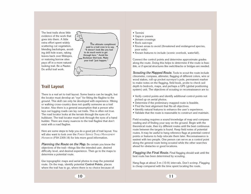
The ultimate compliment paid to a trail crew is to say, “It doesn’t look like you had to do much work to get through here.” Avoid the Bulldozer Bob look. Make your trail “just happen.”
The best trails show littleevidence of the work thatgoes into them. A littleextra effort spent widelyscattering cut vegetation,blending backslopes, avoid-ing drill hole scars, rakingleaves back over fillslopes,or restoring borrow sitespays off in a more natural-looking trail. Be a Master.Do artful trail work.
Trail Layout
There is a real art to trail layout. Some basics can be taught, butthe locator must develop an “eye” for fitting the flagline to theground. This skill can only be developed with experience. Hikingor walking cross-country does not qualify someone as a traillocator. Also there is a general assumption that a person wholays out logging roads can lay out trails. This is often not true.The road locator looks at the terrain through the eyes of abulldozer. The trail locator must look through the eyes of a handbuilder. There are many nuances to the trail flagline that don’texist with a road flagline.
Here are some steps to help you do a good job of trail layout. Youwill also want to look over the FOREST SERVICE TRAILS MANAGEMENT
HANDBOOK (FSH 2309.18) for lots more good information.
Planning the Route on the Map. Be certain you know theobjectives of the trail—things like the intended user, desireddifficulty level, and desired experience. Then go to the maps todetermine a potential route.
Use topographic maps and aerial photos to map the potentialroute. On the map, identify potential Control Points, placeswhere the trail has to go, where there is no choice because of:
11
• Termini• Gaps or passes• Stream crossings• Rock outcrops• Known areas to avoid (threatened and endangered species,
poor soils)• Known features to include (scenic overlook, waterfall).
Connect the control points and determine approximate gradesalong the route. Doing this helps to determine if the route is feas-ible, or if special structures like switchbacks or bridges are needed.
Scouting the Mapped Route. Tools to scout the route includeclinometer, compass, altimeter, flagging of different colors, wire orwood stakes, roll-up pocket surveyor’s pole, permanent markerto make notes on the flagging, field book, probe to check soildepth to bedrock, maps, and perhaps a GPS (global positioningsystem) unit. The objectives of scouting or reconnaissance are to:
• Verify control points and identify additional control points notpicked up on aerial photos.
• Determine if the preliminary mapped route is feasible.• Find the best alignment that fits all objectives.• Identify natural features to enhance the user’s experience.• Validate that the route is reasonable to construct and maintain.
Field scouting requires a sound knowledge of map and compassreading and of finding your way on the ground. Begin with thetheoretical route, then try different routes until the best continuousroute between the targets is found. Keep field notes of potentialroutes. It may be useful to hang reference flags at potential controlpoints or features to help relocate them later. Reconnaissance iseasiest with two people. One person can serve as a control pointalong the general route being scouted while the other searchesahead for obstacles or good locations.
Flagging the Final Route. Final flagging should wait until thebest route has been determined by scouting.
Hang flags at about 3-m (10-ft) intervals. Don’t scrimp. Flaggingis cheap compared with the time spent locating the route.

12
Animals carry off flags, wind blows them down. You also obtainthe best alignment with close flagging.
Flag the centerline. The steeper the sidehill, the more grade isaffected by moving the line up or down the slope. Grade can beseriously compromised by leaving the construction crew too muchlatitude for deciding the final location.
Sometimes you have no choice but to go through a spot thatideally should have been avoided. Make sure the trail can bereasonably constructed through such spots.
One Person Flagging. Stand at a point that is to be thecenterline and tie flagging at eye level. Then move about 3 to 6m (10 to 20 ft) to the next centerline point and sight back to thelast flag. When you have the desired location, tie another flag ateye level.
HINTS FOR LOCATORS
• Large trees often have natural benches on their uphill side. It’s better to locate your trail there than on the downhill side where you’ll sever root systems and generally undermine the tree. Your specifications will tell you how close you can build to the tree. • Look for “natural platforms” for switchbacks. This saves on construction and better fits the land. • Cross ravines at an angle rather than going straight down and up the ravine banks. • Be sure to flag locations for grade dips or Coweeta dips. • Where vegetation is generally dense, patches of sparse vegetation are a good indication of shallow bedrock. • The more difficult the terrain, the more critical it is to flag the centerline location.• Don’t trust your eyeball guess for grade; use your clinometer.
13
Two or More Persons Flagging. A person with a clinometerstands on the centerline point, directs a person ahead to thedesired location, then takes an eye-level shot on that person ifthey are the same height. It is better to take a shot on a rod withbright flagging tied at the height of the clinometer reader’s eye.
When the desired location is determined, the front person hangsa flag and moves ahead. The person with the clinometer movesup to the flag and directs the next shot. A third person can bescouting ahead for obstacles or good locations.

14
Natural Forcesat Work
Dirt, Water, and Gravity
Dirt, water, and gravity are what trail work isall about. Dirt is your trail’s support. Terra firma
makes getting from point A to point B possible.The whole point of trail work is to get dirt where
you want it, and to keep it there. Water is the mostpowerful stuff in your world. Its mission is to takeyour precious dirt to the ocean. The whole point of
trail work is to keep your trail out of water’s grip. Gravity just is...
It is much more important to understand how the forces of waterand gravity combine to move dirt than it is to actually dig dirt,install waterbars, or build puncheon. If you work trails longenough, you will see hundreds of examples of trail structures builtwith little understanding of the forces at hand. Such structuresdon’t work and the dirt goes downhill. You will save time, money,and your sanity if you get grounded in the basic physics first.
Water erodes soil surfaces by picking up soil particles and carry-ing them off. It builds soil surfaces by getting tired and droppingsoil particles. And it alters soil structure by hanging out with soilparticles.
Water in the ‘erode mode’ strips tread surface, undercuts supportstructures, and blasts apart fill on its way downhill. How muchdamage is done depends on the amount of water involved andhow fast it is moving.
Water has “carrying capacity.” More water can carry more dirt.Faster water can carry more dirt. You need to slow water down
15
Figure 4—Too much water and sediment washed this waterbar out. Keep thewater moving until you get the suspended soil where you want it. This soundssimple, but most failed water diversion structures are ones clogged withdeposited soil.
and get it off the trail. When and where you can do that deter-mines what sort of water control or drainage structure you use.
Water has “deposit” ability. If you slow water down, it loses itsability to carry soil. If you abruptly turn or block water, it slowsdown. This has some advantages if you are restoring erodedtread and use check dams to capture waterborne soil. It works toyour disadvantage if your waterbar happens to be the abruptturn and the soil drops, clogging the waterbar (Figure 4).
Water can also affect soil strength. The general rule of thumb isthat drier soils are stronger (more cohesive) than saturated soils,but it is also true that fine, dry soils blow away. The best trailworkers can identify basic soils in their areas and know their wet,dry, and wear properties. They will also know about plantindicators that will tell them about the underlying soil anddrainage.

16
You will have mastered dirt, water, and gravity when you can: • Move surface water off of the trail. • Keep surface water moving, without taking tread mater- ial with it, until it is off of the tread. • Keep trail tread material well drained.
Critter Effects
Gravity has a partner—the Critter. Critters include packstock,pocket gophers, humans, bears, elk, deer, cows, and sheep.Critters will burrow through your tread, walk around the desig-nated (but inconvenient) tread, tightrope walk the downhill edgeof the tread, shortcut the tread, roll rocks on the tread, chew upthe tread or uproot the tread.
Gravity waits in glee for critters to loosen up more soil. If yourecognize potential critter effects (especially from humans, deer,elk, domestic livestock, and packstock), you can beat the systemfor a while and hang onto that dirt. How?
• Don’t build switchbacks across a ridge or other major “gameroute.”
• Don’t let tread obstacles like bogs or deeply trenched treaddevelop.
• Make it inconvenient for packstock to walk the outer edge ofyour tread.
Your trail strategies are only as good as your understanding ofthe critter’s mind.
17
Trail Corridor
Tread
GROUND LINE
Clearing width
➛
➛
➛
➛
➛
➛
➛
Trailbed
➛
➛
Catchpoint
➛Backslope
Embankment
➛
Verticalclearingheight
Hinge point
Shoulder
➛➛
Trail Structure Terminology
Cle
arin
g lim
it
Surface course
➛
Catch point
➛
Fillslope
Trailway
Figure 5—Terms describing the trail corridor. Often there will bedetailed dimensions you need to know.
The trail corridor is a zone that includes thetrail tread and the area above and to the sidesof it. Trail standards typically define the edges
of this area as the “clearing limits.” Vegetationand other obstacles, such as boulders, are
trimmed back or removed from this area to makeit possible to ride or walk on the tread (Figure 5).
The dimensions of the corridor are determined bythe needs of the target user and trail difficulty level.
For example, in the Northern Rockies, trail corridors for traditionalpackstock are cleared 2.5 m (8 ft) wide and 3 m (10 ft) high. Hikertrails are cleared 2 m (6 ft) wide and 2.5 m (8 ft) high. Check withyour local trail manager to determine the appropriate dimensionsfor each of your trails.

18
Figure 6—Vegetation before trail clearing. Each type oftrail has its own requirements for clearing.
Clearing and Brushing
Working to wipe out your trail is no less than that great nuclearfurnace in the sky—Old Sol, the sun. Working in cahoots withthe mad scientist, Dr. Photosynthesis, the sun works an alchemythat converts dirt and water into a gravity-defying artifice calleda plant. Seasoned trail workers will attest to the singular will andincredible power of plants. No sooner is a trail corridor cleared ofplants than they begin a rush toward this new avenue of sunlight.
A significant threat to trail integrity comes from plants growinginto trail corri-dors, or fromtrees fallingacross them.Brush is amajor culprit.Otherencroachingplants such asthistles ordense fernsmay maketravel unpleas-ant or evencompletelyhide the trail. Ifpeople havetrouble travel-ing your tread,they’ll moveover, usuallyalong the loweredge, or maketheir own“volunteer”trail. Cut thisveggie stuffout! (Figure 6).
19
Figure 7—Rocks and logs help to keep the trail in place.And remember that this is a path through nature, not amonument to Attila the Hun.
In level terrain the corridor is cleared an equal distance on eitherside of the tread centerline. Using the hiking trail example, thismeans that the corridor is cleared for a distance of 1 m (3 ft) eitherside of center. Within 300 mm (1 ft) of the edge of the tread, plantmaterial and debris should be cleared all the way to the ground.Farther than 500 mm (1.5 ft) from the trail edge, plants do nothave to be cleared unless they are taller than 500 mm or so. Fallenlogs usually are removed to the clearing limit.
On moderate to steep side slopes, a different strategy is often use-ful. Travel along the lower (outer) edge of the tread is a significantcause of treadfailure. Youcan usetrailsidematerial tohelp holdtraffic to thecenter of thetread. Adowned logcut nearlyflush with thedownhill edgeof the trail willencouragetravelers tomove up toavoid it.Rocks, limbedtrees, and thelike can all beleft near thelower edge ofthe tread toguide trafficback to thecenter(Figure 7).
20
The key is to make sure that the guide material will not interferewith travel on the center of the tread. For example, bikers needenough room for pedals or foot pegs to clear both the backslopeand the guide structures.
On the uphill side of the trail, cut and remove material for a greaterdistance from centerline. For instance, on slopes steeper than 50percent you may want to cut downed logs or protruding branches2 m (6.5 ft) horizontal distance or more from the centerline. Thisis particularly true if you’re dealing with packstock as they tendto shy away from objects at the level of their heads.
Using this “movable corridor” takes some thought. Recognize thatthis may be a difficult decision for inexperienced crews. Continueto revisit the basic reasons for clearing a corridor and the conse-quences of taking or leaving material.
Finally, remember that the “scorched earth” look created by acorridor with straight edges is not very pleasing to the eye. Workwith natural vegetation patterns to “feather” or meander the edgesof your clearing work so they don’t have such a severe appear-ance. Cut intruding brush back at the base of the plant ratherthan in midair at the clearing limit boundary. Cut all plant stemsclose to the ground. Scatter the resulting debris as far as practical.Toss stems and branches so the cut end lies away from the trail(they’ll sail farther through brush as well). Don’t windrow thedebris unless you really and truly commit to burn or otherwiseremove it (and do this out of sight of the trail). Rubbing the cutends of logs or stumps with soil will reduce the brightness of afresh saw cut. In especially sensitive areas, cut stumps flush withthe ground and cover with dirt, pine needles, or moss. Rub dirton stobs or bury them. Remember...this is America the Beautiful!
Some trails may have to be brushed several times a year. Someonce every few years. Doing a little corridor maintenance when itis needed is a lot easier than waiting until plants cause expensiveproblems. Jump on potential problem areas before they becomereal problems.
21
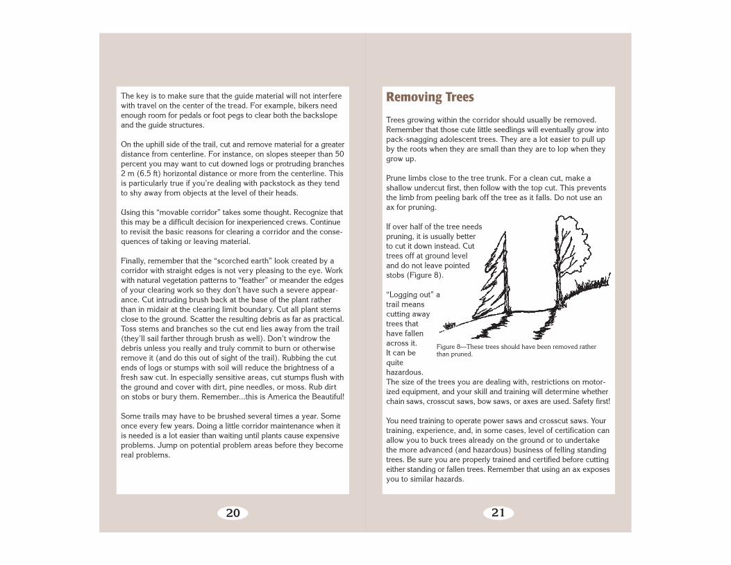
Figure 8—These trees should have been removed ratherthan pruned.
Removing Trees
Trees growing within the corridor should usually be removed.Remember that those cute little seedlings will eventually grow intopack-snagging adolescent trees. They are a lot easier to pull upby the roots when they are small than they are to lop when theygrow up.
Prune limbs close to the tree trunk. For a clean cut, make ashallow undercut first, then follow with the top cut. This preventsthe limb from peeling bark off the tree as it falls. Do not use anax for pruning.
If over half of the tree needspruning, it is usually betterto cut it down instead. Cuttrees off at ground leveland do not leave pointedstobs (Figure 8).
“Logging out” atrail meanscutting awaytrees thathave fallenacross it.It can bequitehazardous.The size of the trees you are dealing with, restrictions on motor-ized equipment, and your skill and training will determine whetherchain saws, crosscut saws, bow saws, or axes are used. Safety first!
You need training to operate power saws and crosscut saws. Yourtraining, experience, and, in some cases, level of certification canallow you to buck trees already on the ground or to undertakethe more advanced (and hazardous) business of felling standingtrees. Be sure you are properly trained and certified before cuttingeither standing or fallen trees. Remember that using an ax exposesyou to similar hazards.

22
Figure 9—If you are uncomfortable withyour ability to safely cut a tree due to thehazards or your lack of experience, walkaway from it!
Some trees may be more safely felled by blasting. Check with acertified blaster to learn where blasting is a feasible alternative.
Removing fallen trees is a thinking person’s game. The requiredtraining will help you think through problems, so we won’t relatethe details here.
Cut the log out as wide as your normal clearing limits on the up-hill side, and out of the “clearing zone” but closer to the trail on thedownhill side. Roll the log pieces off the trail and outside the clear-ing limits on the downhill side. Never leave them across ditchesor waterbar outflows. If you leave logs on the uphill side of thetrail, turn or bed them so they won’t roll or slide onto the trail.
Sometimes you’ll find a fallen tree lying parallel with the trail. Ifthe trunk of the tree is not within the clearing limits and you decideto leave it in place, prune the limbs flush with the trunk.
It is hard to decide whether or not to remove “leaners,” trees thathave not fallen but are leaning across the trail. If the leaner iswithin the trail clearingzone, it should be removed.Beyond that, it is a matterof discretion whether aleaner needs to be cut. Theamount of use on the trail,the time until the trail ismaintained again, thesoundness of the tree, andthe potential hazard theleaner is creating all needto be considered in yourdecision. Felling a leaner,especially one that is hungup in other trees, can bevery hazardous. Onlyhighly qualified sawyersshould do it (Figure 9).Blasting is another way tosafely remove leaners.
23
Felling standing trees (including snags) is statistically one of themost dangerous activities a trail worker can engage in. Simplyput, do not even consider felling trees unless you have beenformally trained and certified. Bringing in a trained sawyer ischeaper than bringing in a coroner.
24
Trail Foundation
The Trailbed
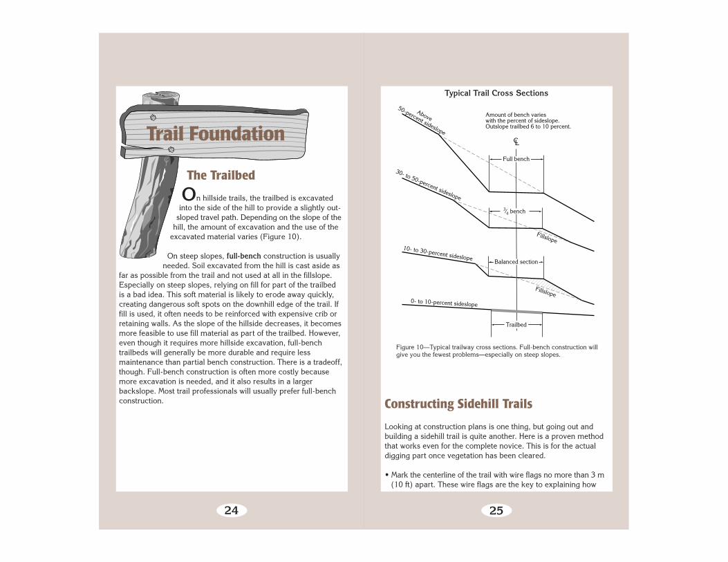
On hillside trails, the trailbed is excavatedinto the side of the hill to provide a slightly out-
sloped travel path. Depending on the slope of thehill, the amount of excavation and the use of the
excavated material varies (Figure 10).
On steep slopes, full-bench construction is usuallyneeded. Soil excavated from the hill is cast aside as
far as possible from the trail and not used at all in the fillslope.Especially on steep slopes, relying on fill for part of the trailbedis a bad idea. This soft material is likely to erode away quickly,creating dangerous soft spots on the downhill edge of the trail. Iffill is used, it often needs to be reinforced with expensive crib orretaining walls. As the slope of the hillside decreases, it becomesmore feasible to use fill material as part of the trailbed. However,even though it requires more hillside excavation, full-benchtrailbeds will generally be more durable and require lessmaintenance than partial bench construction. There is a tradeoff,though. Full-bench construction is often more costly becausemore excavation is needed, and it also results in a largerbackslope. Most trail professionals will usually prefer full-benchconstruction.
25
Figure 10—Typical trailway cross sections. Full-bench construction willgive you the fewest problems—especially on steep slopes.
Typical Trail Cross Sections
Constructing Sidehill Trails
Looking at construction plans is one thing, but going out andbuilding a sidehill trail is quite another. Here is a proven methodthat works even for the complete novice. This is for the actualdigging part once vegetation has been cleared.
• Mark the centerline of the trail with wire flags no more than 3 m(10 ft) apart. These wire flags are the key to explaining how
0- to 10-percent sideslope
10- to 30-percent sideslope
30- to 50-percent sideslope
Fillslope
Fillslope
CL
Full bench
3⁄4 bench
Balanced section
Trailbed
Above
50-percent sideslope
Amount of bench varieswith the percent of sideslope.Outslope trailbed 6 to 10 percent.

26
CL
This depicts a balanced bench. For a full bench, wire flagends up on the outside edge of the excavated bench.
Bench—cut down to h
ere.
Imagine a level line from thebase of the flag into the bank.
Fill
Figure 11—Basic sidehill trail building.
➛
Cut and Fill
to dig the tread, and they keep the diggers on course.• Remove leaf litter, duff, and humus down to mineral soil. To
mark the area to be cleared, straddle the flag facing the uphillslope. Swing your Pulaski or other tool. Where the tool strikesthe ground is approximately the upper edge of the cut bank.The steeper the slope, the higher the cut bank. Do this at eachcenterline flag, then scratch a line between them. This definesthe area to be raked to mineral soil. Clear about the same dist-ance below the flag. Keep the duff handy, as it will be used later.Don’t clear more trail than can be dug in a day unless you knowit isn’t going to rain before you can complete the segment.
• For a balanced bench trail, the point where the wire flag entersthe ground is the finished grade. Scratch a line between flagsto keep yourself on course. Facing the uphill slope, begin diggingabout 150 mm (6 in) from the flag cutting back into the slope.Imagine a level line drawn from the base of the flag into thebank. Dig into the bank down to this line, but not below (Figure11). Pull the excavated material to the outer edge. Tamp this fillmaterial as you go. On a full-bench trail, the wire flag essentiallyends up at the outside edge of the trail. For less than a full-benchtrail, the flag ends up somewhere between the centerline andoutside edge. Keep this in mind when you place the wire flags.
• There is a tendency to want to stay facing uphill. To properlyshape the tread, you need to stand on the trail and work thetread parallel to the trail direction to level out the toe of thecutslope and to get the right outslope.
27
Figure 12—If your ankles start to roll, there is too much outslope.
Excess Outsloping
• There is a tendency to make the trail too narrow. If the width ofrough tread equals the length of a Pulaski handle, the narrowerfinished tread will be about right for a good hiking trail.
• Make sure grade dips and other drainage structures are flaggedand constructed as you go.
• If you try to slope the cut bank close to the original surface,you will usually get somewhere close to what is needed. Sloperatios are hard to understand. Instead, look at the natural slopeand try to match it.
• Round off the top of the cutslope. The easiest way to do this isto rake parallel to the cut edge with a fire rake.
• The best way to check the outslope is to walk the tread. If youcan feel your ankles rolling downhill, there is too much outslope(Figure 12). The outslope should be barely detectable to theeye. If you can see a lot of outslope, it’s probably too much. Apartially filled water bottle makes a good level.
• Once the bench construction is finished, stand on the treadand pull the reserved duff up onto the fillslope with a fire rake.This helps stabilize the fill (especially important in high rainfallareas), and makes the new trail look like it has been there for
Water bottleas a level.

28
While often described as a percent,slopes are also described as a ratio of verticalto horizontal, or “rise” to “run.” The protocolfor metric (SI) notation continues this tradition,with the additional change of eliminating fractions
from the notation. For slopes flatter than 1:1,express the slope as a ratio of one unit vertical
to the number of horizontal units. For slopessteeper than 1:1, express the slope as the ratio
of the number of vertical units to one unithorizontal. Figure 13 shows examples. TRANSPORTATION ENGINEERS HAVEUSED A DIFFERENT SYSTEM—AND STILL
DO—FOR NONMETRIC SLOPE MEASURE-MENTS. MAKE SURE YOU UNDERSTAND
WHICH SYSTEM IS BEING USED.
years. Be careful not to create a berm with the duff. On full-benchtrails there will be no need for the duff, as the outside edge of thetrail has not been disturbed. Sometimes contract specificationscall for scattering rather than reserving the duff.
Figure 13—Slopes are noted in metric as a ratio of vertical tohorizontal, or “rise” to “run.”
1-meterhorizontal
1-metervertical
0.5-metervertical
1-meterrise
0.5-meterrun
1:1 backslope
1.3-meterhorizontal
1:2.6 backslope
2:1 backslope
29
Look at the surrounding landscape and soil to see what is stable. A handy rule of thumb is to create a some- what gentler slope than you think necessary. Although you will initially expose more raw soil, the chances of it remaining stable and revegetating are greater than if you leave a backslope so steep that itkeeps sloughing.
Backslope
The backslope is the excavated, exposed area of the trailwayabove the tread surface. Backslopes range from near vertical (inrock) to 1:2 in soils having little cohesion. Backslopes cannot besteeper than the exposed material’s ability to stay put during typi-cal climatic conditions. Most inexperienced crews construct back-slopes that exceed the parent material’s angle of repose. Trans-lation? The slope usually fails within a year, blocking the tread.
A second option is to construct a crib wall and use fill to supportthe entire tread surface. This can be less obtrusive than hugebackslope excavationsand more stable, if thewall is well constructed.Much less backslope, ifany, may be needed.
Fillslope
The fillslope is thatarea of the trail below(downslope from) thetread surface. A full-bench tread, of course,will not have any fillassociated with this sideof the trail. Fillslopes are critical. If you take care of the downhillside of the trailway, you’ll avoid the vast majority of problemsassociated with trail maintenance.

30
Borrow Pits
Often you will need fill material. The hole you dig is called aborrow pit. It should be as close to the work site as possible, butscreened from view. The material in the pit also needs to be suit-able for the desired use. Good choices are soils with a balancedmixture of different size particles. Sand and gravel work well. Sodo small, well-graded angular rocks.
Compare existing trail tread materials with borrow sources. Con-sider the proportions of gravel, sand, and fines. Individual “fine”particles are not visible to the naked eye and are classified as siltor clay. If the proportions of gravel, sand, and fines are similar,you can expect the borrow materials to perform as well as theexisting trail tread materials. If the borrow source has a smallerproportion of fines, you can expect better performance underwet conditions.
Soils from bogs are normally not suitable for tread fill becausethey lose strength when they become wet. These dark organicsoils are identified by musty odor when damp. In temperate partsof the country you’ll want to avoid organic soils. In the arid South-west, however, organic material can be added to dry clay to keepit from blowing away.
Creek bottoms that are replenished by storms and seasonal waterflow, and the base of slopes or cliffs where heavy runoff or gravitydeposit sand and gravel, are good places to look. Don’t destroyaquatic or riparian habitat with your pit.
Save all squares of vegetation removed from the top of the pit.You’ll need them for restoration. Place them in the shade and keepthem moist by covering them with wet burlap. To rehabilitate,grade the pit out to natural contours with topsoil and debris, thenrevegetate. Camouflage the area and access trails with bouldersand dead wood.
31
Tread
Tread Surface
Tread is the actual travel surface of the trail.This is where the rubber (or hoof) meets the
trail. Tread is constructed and maintained tosupport the designed use for your trail.
Most trail construction revolves around making suresolid, obstacle-free tread is established and enough
protection is provided to keep it in place. If you don’t do a goodjob of locating, constructing, and maintaining tread, the users willfind their own pathways instead.
Outsloping is the first line of defense against tread erosion. Anoutsloped tread is one that is lower on the outside or downhill sideof the trail than it is on the inside or bank side. Outsloping letswater run naturally off the trail. A 500-mm (2-ft) wide trail wouldhave an outside edge 30 to 60 mm (1.2 to 2.4 in) lower than theinside edge. Tread is also the travel surface on structures like turn-pike and puncheon. Tread, whenever elevated, should be slightlycrowned to drain better.
Tread Creep
Does your sidehill trail display:
• Exposed bedrock or roots along the upper side of the tread?• Daisy-chained tread alignment (Figure 14)?• Pack bumpers, jump-offs, and prominent tread anchors?

32
Figure 14—Some classic signs of tread creep. This trail needs help now.
All three are indications that the tread surface has been erodedand compacted by travel along the lower edge. Insidious treadcreep at work. Tread creep should be arrested or the trail willeventually become very difficult or dangerous to travel.
What causes tread creep? The answer is simple. Most livestock,two-wheeled traffic, and some people have a natural tendency towalk the outside edges of sidehill trails. Sloughing makes the edgethe flattest place to walk. As the tread moves downhill, it alsonarrows, with the result that more traffic travels closer to the outeredge. Other causes of tread creep are constructing a trail that istoo narrow or with cutslopes that are too steep. Your job is tobring the trail back uphill to its original location and keep it there(Figure 15).
One of the best ways to do this is to take advantage of large sta-tionary objects (guide structures) to prevent animals and peoplefrom walking the edge. Trees, log ends, rocks, and stumps leftclose to the downhill edge of the trail will keep animals walkingcloser to the middle. Guide structures should be no more than500 mm (1 ft) high so they will not catch animals’ packs.
33
➛
Causes of Trail Creep
Figure 15—Tread creep at work—sloughing and soft fillslopes.
Rounded hinge point
Slough spreadsacross tread
Fill edge breaks down
➛
➛
Curb rocks need to be well anchored, and they should be placedat random distances so they don’t look like a wall or trap wateron the tread.
Tread between these anchors will creep downhill creating a situa-tion where the trail climbs over every tread anchor and descendsagain. At the bottom of these “dips,” water and sediment collect.This is the weakest portion of the tread and the most prone tocatastrophic failure. The tread can be so soft that packstock maypunch completely through the tread (called a step-through) orbicycles or dirt bikes may collapse the edge. The result can be abad wreck.
Where soil is in short supply, you may have to install a short cribwall and haul in tread material. Thin tread on bedrock will notusually stay put without some support. If normal slough removaldoes not work on more substantial soils, the tread should be

Minimum length of rock is 450 mm.Bury at one third of rock into the ground.
ground
Natural
Figure 16—Guide rock properly installed to help prevent tread creep.
Stabilizing Tread Creep
benched back into the slope in the original alignment. Guidestructures should be installed on the outside edge of the tread tokeep traffic toward the center.
A note on guide structures: If you use a rock, be sure it is bigenough that at least one-third of it may be buried (so people andbears won’t roll it away) and it will still be obtrusive enough thathikers and horses won’t walk over it (Figure 16). Log ends shouldbe sawed back at an angle if the top edge of the log is more than500 mm (20 in) above the tread. If you have really substantialberm to remove, leave 1-m (3-ft) long portions at 3- to 5-m (10-to 15-ft) intervals with the ends feathered into the fillslope to serveas guide structures.
Slough and Berm
On hillside trails, slough (pronounced “sluff”) is soil, rock, anddebris that has moved downhill to the inside of the tread,narrowing it. Slough needs to be removed (Figure 17).Removing slough is hard work, and is often not done adequately.Leaving slough is another reason trails “creep” downhill.
34 35
Figure 17—Remove the slough and berm, leaving the trail outsloped sowater will run off. One fist’s worth of drop for the length of a Pulaski isa good rule of thumb.
Reestablishing Outslope
Loosen compacted slough with a mattock or Pulaski, then removethe soil with a shovel or McLeod. Use excess soil to fill holes inthe tread, or on the downhill side of waterbars. Reshape the treadto restore its outslope. Avoid disturbing the entire cutbank unlessabsolutely necessary. Chop off the toe of the slough, and blendthe slope back into the cutbank.
Berm is soil that has built up on the outside of the tread, forminga barrier that prevents water from running off the trail. Berms area natural consequence of tread surface erosion and redeposition,and of inadequate compaction during construction. Berms preventwater from flowing off the trail. Water runs down the tread itself,gathering volume and soil as it goes. Berm formation is the singlelargest contributor to erosion of the tread surface. Removingberms is almost always the best practice. Observe erosion on trailswith and without berms, see what works best in your area, andask the project leader for a recommendation if you are in doubt.
Slough Berm

36
Berms also trap water in puddles on level portions of tread and atthe bottom of dips. Trapped water contributes to soil saturation,greatly reducing tread cohesion. Saturated tread material is proneto mass wasting and step-throughs.
Berms, especially when associated with tread creep, may form afalse edge. False edge is unconsolidated material, often includingsignificant amounts of organic material, that has almost no abilityto bear weight. This is probably the least stable trail feature onmost trails and the major contributor to step-throughs and wrecks.
Berms should not be constructed intentionally. Guide structures oreven guard rails, if appropriate, should be combined with treadoutsloping to keep users on the center of the trail and water of fof it.
Tread Maintenance
Maintain tread at the designed width. This means filling ruts, holes,and low spots. It includes removing obstacles such as protrudingroots and rocks. It also means repairing any sections that havebeen damaged by landslides, uprooted trees, washouts, or boggyconditions.
Tread maintenance aims for a solid, outsloped surface. Removeall the debris that has fallen on the tread, the sticks and stonesand candy wrappers. Pull the lower edge berm back onto thetread surface and use it to restore the outslope. Use any sloughmaterial in the same fashion. Remove and widely scatter organicdebris well beyond the clearing limits, preferably out of sight.
37
Rule of thumb for roots— if perpendicular to the tread, fairly flush, and not a tripping hazard, leave them. Remove roots that are parallel with the tread. They cause erosion and create slipping hazards. Look for the reason the roots were exposed and fix that problem.
Removing Roots and Stumps
Removing roots and stumps is hard work. Explosives and stumpgrinders are good alternatives for removing stumps, but chancesare you’ll have to do the work by hand. A sharpened pick mattockor Pulaski is most often used to chop away at the roots. If you arerelying on some type of winch system to help you pull out thestump, be sure to leave the stumps high enough to give yousomething to latch on to for leverage.
Not all roots and stumps are problems. You should not have toremove many large stumps from an existing trail. Before you doso, consider whether a stump was left the last time around to helpkeep the trail from creeping downhill.
Rock Removal
Rock work ranges from shoveling cobble to blasting solid rock. Both ends of the spectrum are often specialty work. The good blaster can save a crew an astounding amount of work. Some- one building a rock retaining wall may be a true artisan, creating a structure that lasts forcenturies. The key to any decent rock work is good planning andfinely honed skills.
The secret to moving large rocks is to think first. Plan out wherethe rock should go, and anticipate how it might roll. Be patient—moving rock in a hurry almost always results in the rock endingup in the wrong location. Communicate with all the crew abouthow the task is progressing and what move should occur next.

38
Remember that the two most common injuries in rock work are pinched (or smashed) fingers and tweaked (or blown out) backs. Both sets of injuries are a direct result of using muscles first and brains last. High-quality rock work is almost always a methodical, even tedious task. Safe work is ALWAYS faster than taking time out for a trip to the infirmary.
Tools of the trade include: • Lots of high-quality rockbars; don’t settle for the cheap digging bars, you need something with high tensile strength. • Pick mattock. • Sledge hammer. • Eye protection, gloves, and hardhat; don’t even think of swinging a tool at a rock without wearing these. • Gravel box, rock bag, rucksack, rock litter; items useful for carry- ing rock of various sizes. • Winch and cable sys- tems; some rocks can be dragged or lifted into place.• All sorts of motorized equipment, including rock drills and
breakers.
Blasting is useful for removing rocks or greatly reducing their size.Careful blasting techniques can produce gravel-sized material.Motorized equipment can be used to split boulders or to grinddown projecting tread obstacles. Chemical expansion agentspoured into drilled holes will break large rocks without explosives.Drills and wedges can be used to quarry stone for retaining wallsor guide structures.
Your specific trail maintenance specifications may call for remov-ing embedded rocks. Use good judgment here. Often very largerocks are better removed by blasting. Other solutions includeramping the trail over them, or rerouting the trail around them.
Rocks should be removed to a depth of at least 100 mm (4 in)below the tread surface, or in accordance with your specific trailstandards. Simply knocking off the top flush with the existingtread may mean a future obstacle as erosion removes soil fromaround the rock.
39
When dealing with rocks, work smarter, not harder. Skidding rocks is easiest. Rolling them is sometimes necessary. Lifting rocks is the last resort.
Rockbars work great for mov-ing medium and large rocks.Use the bars to pry rocks outof the ground and then to guidethem around. When crew mem-bers have two or three barsunder various sides of a largerock they can apply leverageto the stone and virtually floatit to a new location with arowing motion. Use smallrocks or logs as a fulcrumfor better leverage.
It may seem like fun at the time, but avoid the temptation to kicka large stone loose. When rocks careen down the mountainsidethey may knock down small trees, gouge bark, wipe out trailstructures, and start rockslides.
Even worse is the possibility an out-of-control rock might crossa trail or road below you, hitting someone. If there is any possi-bility of people below, close the trail or road, or post sentries insafe locations to warn travelers of the danger.
You might construct a barrier by laying logs against two trees tostop a rolling rock before it gains much momentum. Once a rockis loose, do not try to stop it.
When you need to lift rocks, be sure to keep your back straightand to lift with the strong muscles of your legs. Sharing the burdenwith another person is sometimes a good idea.
To load a large rock into a wheelbarrow, lean the wheelbarrowback on its handles, roll the rock in gently over the handles (orrocks placed there) and tip the wheelbarrow forward onto itswheels. Keep your fingers clear any time you deal with rocks.
Small stones are often needed for fill material behind crib walls,in turnpikes and cribbed staircases, and in voids in talus sectionsof trail. Buckets and wheelbarrows are handy here. So are canvascarrying bags. If you are part of a large crew, handing rocksperson-to-person often works well. Remember, twisting yourupper body while holding a heavy rock usually isn’t a good idea.

40
Surface WaterControl
Trail tread
Prevailing grade
Trail tread outsloped 2% thru this area10%
➛
➛
10%
➛
➛
➛
➛
➛
➛
➛
➛ Grade dips➛Grade dips
➛
➛
Coarse material that won't scour
Typical Dip Profile
Figure 18—Grade dips are much more effective than waterbars andrequire less maintenance. Along with outsloping, they are the drainagestructure of choice.
Typical 3 m
Typical1.5 m
➛
➛
41
that lies lightly on the land will take advantage of each localdrainage to remove water from the tread (Figure 18) as the trailwinds around trees and rocks. The terrain dip, which uses existingterrain as the control point for the grade reversal, is a naturalpart of the landscape.
The beauty of terrain dips is that water collected from the hillsideis not intercepted and carried by the tread. These grade dips arethe most unobtrusive of all drainage structures if constructed withsmooth grade transitions, and they require very little maintenance.Be sure to protect the drain outlet by placing guide structuresalong the lower edge of the tread above or below the outlet.
Another kind of grade dip is the rolling grade dip, which consistsof a short reversal of grade in the tread. These can be designedinto most sidehill trails. If a trail is descending at 7-percent grade,a short climb of, say, 3 to 5 m (10 to 20 ft) at 3 percent, followed
Diverting surface water off the trail shouldbe near the top of your list of priorities. Run-
ning water erodes tread and support structuresand can even lead to loss of the trail itself.
Standing water often results in soft boggy treador tread and support structure failure. Water is
wonderful stuff—just keep it off the trail.
The very best drainage structures are thosedesigned and installed during the original construc-
tion. These include outsloping the tread and grade dips.We’ve already discussed outsloping. Let’s move on to the nextbest drainage choice, grade or drain dips. The classic mark ofgood drainage is that it is self maintaining, requiring minimal care.
Grade Dips
The best grade dips are designed and built during the originalconstruction. These are also called terrain dips, Coweeta dips,and swales. Other versions, often called rolling grade dips, ordrain dips, can be built on most sidehill trails or constructed toreplace waterbars. The basic idea is to use a reversal in grade toforce water off the trail without the need for any other structure.
Terrain dips use grade reversal to take advantage of natural dipsin the trail. These need to be planned into the trail when it is firstlaid out. The grade of the trail is reversed for about 3 to 5 m (10to 15 ft), then “rolled” back over to resume the descent. A trail
42
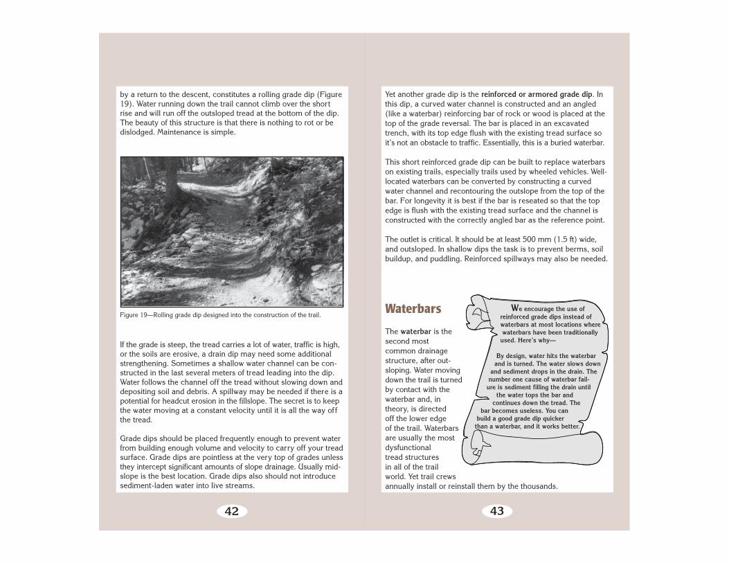
Figure 19—Rolling grade dip designed into the construction of the trail.
by a return to the descent, constitutes a rolling grade dip (Figure19). Water running down the trail cannot climb over the shortrise and will run off the outsloped tread at the bottom of the dip.The beauty of this structure is that there is nothing to rot or bedislodged. Maintenance is simple.
If the grade is steep, the tread carries a lot of water, traffic is high,or the soils are erosive, a drain dip may need some additionalstrengthening. Sometimes a shallow water channel can be con-structed in the last several meters of tread leading into the dip.Water follows the channel off the tread without slowing down anddepositing soil and debris. A spillway may be needed if there is apotential for headcut erosion in the fillslope. The secret is to keepthe water moving at a constant velocity until it is all the way offthe tread.
Grade dips should be placed frequently enough to prevent waterfrom building enough volume and velocity to carry off your treadsurface. Grade dips are pointless at the very top of grades unlessthey intercept significant amounts of slope drainage. Usually mid-slope is the best location. Grade dips also should not introducesediment-laden water into live streams.
43
We encourage the use of reinforced grade dips instead of waterbars at most locations where waterbars have been traditionally used. Here’s why—
By design, water hits the waterbar and is turned. The water slows down and sediment drops in the drain. The number one cause of waterbar fail- ure is sediment filling the drain until the water tops the bar and continues down the tread. The bar becomes useless. You can build a good grade dip quickerthan a waterbar, and it works better.
Yet another grade dip is the reinforced or armored grade dip. Inthis dip, a curved water channel is constructed and an angled(like a waterbar) reinforcing bar of rock or wood is placed at thetop of the grade reversal. The bar is placed in an excavatedtrench, with its top edge flush with the existing tread surface soit’s not an obstacle to traffic. Essentially, this is a buried waterbar.
This short reinforced grade dip can be built to replace waterbarson existing trails, especially trails used by wheeled vehicles. Well-located waterbars can be converted by constructing a curvedwater channel and recontouring the outslope from the top of thebar. For longevity it is best if the bar is reseated so that the topedge is flush with the existing tread surface and the channel isconstructed with the correctly angled bar as the reference point.
The outlet is critical. It should be at least 500 mm (1.5 ft) wide,and outsloped. In shallow dips the task is to prevent berms, soilbuildup, and puddling. Reinforced spillways may also be needed.
Waterbars
The waterbar is thesecond mostcommon drainagestructure, after out-sloping. Water movingdown the trail is turnedby contact with thewaterbar and, intheory, is directedoff the lower edgeof the trail. Waterbarsare usually the mostdysfunctionaltread structuresin all of the trailworld. Yet trail crewsannually install or reinstall them by the thousands.
44
On grades less than 5 percent, waterbars are less susceptible toclogging (unless they serve a long reach of tread or are in veryerodible tread material). On steeper grades (15 to 20 percent),waterbars are very prone to clogging if the bar is at less than a 45°angle to the trail. Waterbars are mostly useless at grades steeperthan 20 percent. At these grades a very fine line exists betweenclogging the drain and eroding it (and the bar) away.
Most waterbars are dysfunctional because they are not installed atthe right angle and are too short. The waterbar needs to be anchored300 mm (12 in) into the cutslope and still extend 300 mm (12 in)into the fillslope. If your tread is 600 mm (24 in) wide, the bar mustbe 1.7 m (5 ft 6 in) long to be correctly installed at a 45° angle. Abar fitted at an angle of 60° must be 2.4 m (7 ft, 7 in) long. Widertread requires a longer bar. When the bar is cut too short, theusual response is to install it at a lesser angle. Then it clogs.
Poorly constructed and maintained waterbars also become obsta-cles. Most waterbars are installed with one-third to one-half of thebar material above the existing tread surface. Some crews eveninstall bars with exposed faces taller than 150 to 200 mm (6 to 8in). On grades steeper than 7 percent (particularly in erodiblesoils), the soil placed on the tread below the waterbar is rapidlylost to traffic and water erosion. The structure becomes a “lowhurdle” for travelers.
Wimpy little wooden bars less than 150 mm (6 in) in diameter wearor clog quickly into uselessness. Often they rot away in just a fewyears. Another problem with wooden waterbars is that horseskick them out.
Cyclists of all sorts hate wooden waterbars because of the hazardthey present to wheeled traffic. The exposed angled surface canbe very slippery, leading to crashes when the wheel slides side-ways down the face of the bar. The rider continues down the trailwithout the cycle. As the grade increases, the angle of the bar(and often the face height) is increased to prevent sedimentation.This raises the crash-and-burn factor.
45
Riprap tray➛
➛ ➛
➛
➛
➛
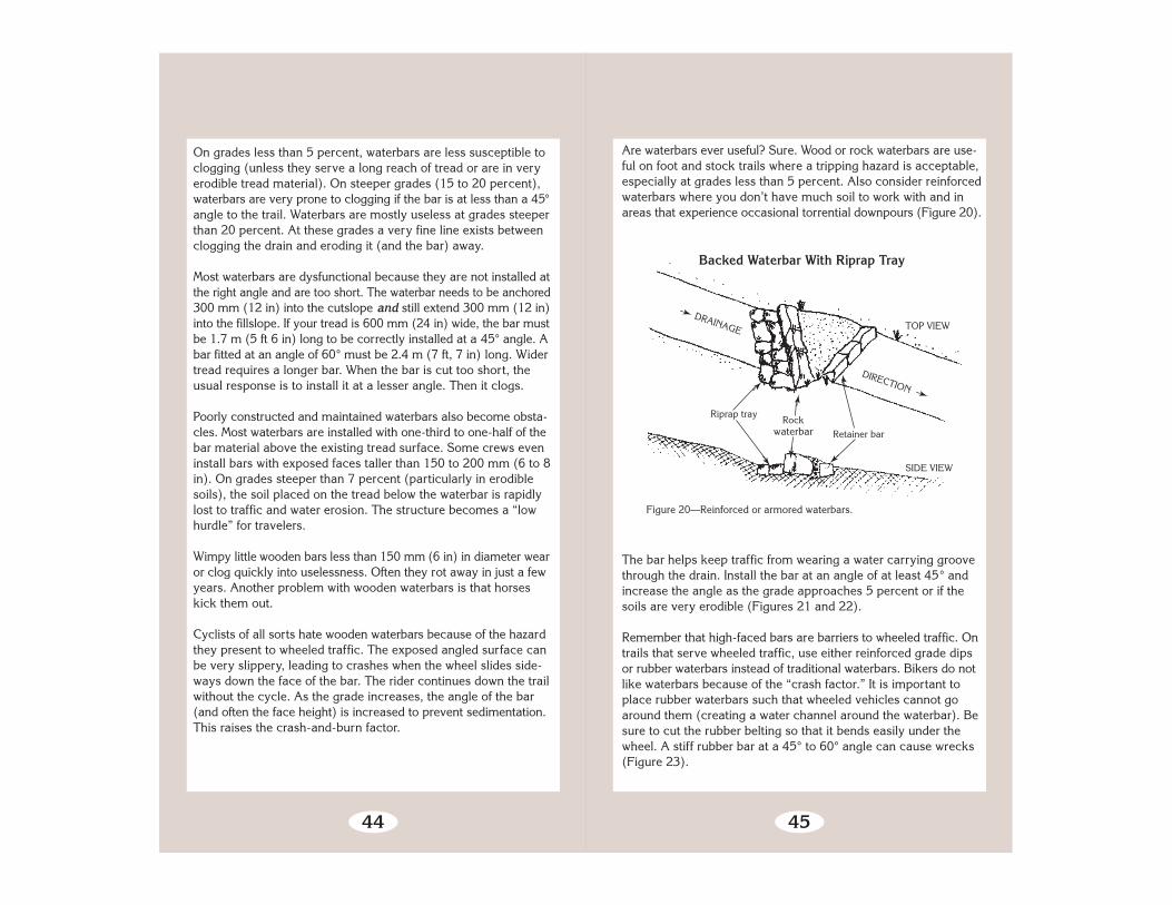
Figure 20—Reinforced or armored waterbars.
Backed Waterbar With Riprap Tray
DRAINAGE DIRECTION ➛
Rockwaterbar Retainer bar
➛
Are waterbars ever useful? Sure. Wood or rock waterbars are use-ful on foot and stock trails where a tripping hazard is acceptable,especially at grades less than 5 percent. Also consider reinforcedwaterbars where you don’t have much soil to work with and inareas that experience occasional torrential downpours (Figure 20).
The bar helps keep traffic from wearing a water carrying groovethrough the drain. Install the bar at an angle of at least 45° andincrease the angle as the grade approaches 5 percent or if thesoils are very erodible (Figures 21 and 22).
Remember that high-faced bars are barriers to wheeled traffic. Ontrails that serve wheeled traffic, use either reinforced grade dipsor rubber waterbars instead of traditional waterbars. Bikers do notlike waterbars because of the “crash factor.” It is important toplace rubber waterbars such that wheeled vehicles cannot goaround them (creating a water channel around the waterbar). Besure to cut the rubber belting so that it bends easily under thewheel. A stiff rubber bar at a 45° to 60° angle can cause wrecks(Figure 23).
TOP VIEW
SIDE VIEW

46
Figure 21—Waterbars need to be constructed at a 45 to 60° angle to the trail.Water should run off the trail before hitting the waterbar.
47
Square treated timber 200 mm
Embed log 1⁄3 (min.)Log 300 mmdiameter
40d barbed orring shank nails
➛
ANCHORING METHODS
50 by 450 mmsquare hardwoodstakes
Trail treadRock anchor Trail tread
➛
100 mm (min.)
Embed 1⁄3 (min.)Steel pin flush with top, rebar #4 by 450 mm
Figure 22—Logs used for waterbars need to be peeled (or treated with preserv-ative), extended at least 300 mm (12 in) into the bank, staked or anchored,and mostly buried.
➛
➛Embed log 300 mm(min.) into bank.
➛
➛Extend log 300 mmbeyond edgeof trail.
Top of waterbar is 150 mmabove surface on upgrade side.
➛
Log or Treated Timber Waterbar and Anchors
➛Down grade
Toe of bank
➛
➛
Skewwaterbar45 to 60°
Outslo
pe to
day
light
➛
➛
Typi
cal o
utslo
pe
6 to
10%
➛
Log flushwith tread ondown-gradeside.

48
Figure 23—Rubber belt waterbars are good choices on trails used by wheeledvehicles. They are not as good as reinforced grade dips.
Conveyor beltrubber
T R A I L
T R E A D
45° to 60° angle from trail tread
Rubber Belting Waterbar
Belting 10 mm thick
Trail tread surface
Excavate and compact around waterbar.
50 x 150 mm treated lumber on each side
50 mm
Make cuts in belting 300 mmapart for better spring-back.
30d galvanized nailson alternate sides
Keep nails a minimum of50 mm from edges of timber.
Treated timber
Nailing and Cutting Detail
150 mm
200 mm
➛
➛
➛
➛
➛
➛
➛
➛
150mm
➛
➛
➛
Belting
➛
➛
➛
➛
➛
➛
➛
➛
➛➛
Lag screws, bolts, or30d ringshank nails
Treated lumber(50 x 150 mm)
49
Think of your waterbar (wood or rock) as a backup to a dip in the trail. Dig the bar first. Make sure it is seated flush, anchored into the cutslope, and at a good angle. Then construct the dip and outlet to match.
For rock waterbars, use rectangular rocks, “chunkers,” butted together, not over- lapped. Start with your heaviest rock at the downhill side—that’s your “keystone.” Lay rocks in from there until you tie into the bank.
Maintaining the Drain
The number one enemy of simple drains is sediment. If the drainclogs, the water you are trying to get rid of either continues erod-ing its way down the tread, or just sits there in a puddle. Your jobis to keep that water off, Off, OFF the tread!
The best drains are “self cleaning.” But in the real world mostdrains collect debris and sediment; this must be removed beforethe drain stops working. Since a long time may pass betweenmaintenance visits, the drain needs to handle annual high volumerunoff without failing.
Most problem drains are waterbars. If the water is slowed by hit-ting the waterbar, sediment builds up. This can be compoundedby inadequate outsloping or an outlet that is too narrow. The extratime it takes to rebuild the offending bar into a functional drain willpay off almost immediately (Figure 24).
The best cure for a waterbar that forces the water to turn tooabruptly is to rebuild the structure into a reinforced grade dip. Thereset bar and curved water channel keep the sediment-laden

50
Figure 24—The key to waterbar maintenance is to ensure that sediment will notclog the drain before the next scheduled maintenance. Embed the rocks orlogs a little deeper, cover them with soil, and you have a reinforced grade dip.
water moving through the outlet. If this is not an option, the nextbest move is to reset the waterbar at a steeper angle. Usually alonger bar will be needed.
TR
AIL
TR
EA
D
Downslope—directionof water flow
Reinforce outlet area if eroded.
Waterbarconstructed at 45° angle.Reset loose ormissing rocksand logs.
Thoroughly dig material
out of this area—at least two
shovel blades wide. Use for backing
below waterbar.
51
A lot of learning takes place when you slosh over a wet trail in a downpour and watch what the water is doing and how your drains and structures are holding up.
If a lot of tread has eroded below the bar, reset the bar so it isflush with the existing tread height. Regrade the water channeland outlet drain. On gentle trails, tamp the excavated mineral soilsediment into the tread on the downhill side of the bar. Scatter anyorganic debris well off the trail.
At grades steeper than 7 to 10 percent, or in highly erodible soils,borrow material placed below the bar will usually erode awayquickly. This is particularly true on waterbars with high faces.Downhill traffic, especially packstock, will step in the same placeevery time and dislodge any new material you place there. If asignificant step-off exists below the bar, reseat the bar flush withthe existing tread level and deepen the drain above the bar.
Dig drains and leadoff ditches wide enough to prevent cloggingby debris, and graded so water does not slow before it is off thetrail. Ditches that allow water to return to the tread below the drainneed to be reconstructed so this doesn’t happen.
You may need to install additional water control structures iferosion is evident. Figure out where the water is coming from andwhere it is likely to go. Think about soil type, slope gradient,distance of flow, and volume of water before you start moving dirt.
Eroded trails do not alwaysbecome major problems.Many eventually stabilize ifthe trail surface is rocky, anduse, water, and slopesare moderate. The key ques-tion is whether the loss oftread will materially affectthe designed challenge andrisk levels of the trail. If not,the erosion isn’t significant.It is exceedingly rare for aneroding trail to have a signif-icant effect on aquatic or riparian habitat or stream function.

52
Ponding
Adequate puddle drains are important. Puddles may produceseveral kinds of tread damage. Traffic going around puddles maywiden the tread (and eventually the puddle). Standing waterusually weakens the tread and fillslopes. It can cause a bog todevelop if the soils are right. Traffic on the soft lower edge of apuddle can lead to step-throughs and cause tread creep.
When a crew takes a swipe at the berm with a shovel or kicks ahole through it—that’s useless puddle control. These small open-ings are rapidly plugged by floating debris or the mud-mooshingeffect of passing traffic. The puddle lives on.
Effective puddle prevention requires constructing a wide drain.The ultimate drain is when the entire section of tread is outsloped.If terrain prevents such outsloping, the next best solution is to cuta puddle drain at least 600 mm (24 in) wide extending across theentire width of the tread. Dig the drain deep enough to ensure thatthe water can escape the tread. Feather the edges of the drain intothe tread so travelers don’t trip over them. Plant guide structuresalong the lower edge of the tread at either side of the drain to keeptraffic in the center. In a really long puddle, construct several drainsat what appear to be the deepest spots.
Trails in Wet Areas
Very few critters like to get their feet wet.There are a few exceptions, of course. Otters,
beavers, goofy retriever dogs, motorcyclists,and most young children like to jump right in.
But the rest of us—horses, llamas, and stodgyadult hikers—will often go to great lengths to
avoid getting our feet wet or going for anunplanned swim. This section deals with a rangeof options for getting trail traffic from one side ofwet ground to the other.
Because nearly every technique for fixing trails in boggy areas isexpensive and needs to be repeated periodically, relocating theproblem section of trail should be considered first. Scouting forsuitable places to relocate trails and reviewing soil maps will betime well spent. The alternative route should bypass extensiveboggy areas, be on a slope for better drainage, and have mineralrather than organic soil for its tread. Don’t reroute a problem sec-tion of trail to another boggy piece of ground. If you do, the resultwill be two problem sections instead of one.
Sometimes, improved drainage will cure the problem. If so, thisis a much less costly solution than other alternatives. Placingstepping stones is another technique for crossing bogs andstreams. Stepping stones should be large, fairly flat on top, andpartially buried in the streambed. Space the stones for the aver-age stride, remembering that trails are for kids, too. It shouldn’tbe necessary to jump from stone to stone.
Moving up in cost and complexity, two types of structures—turn-pike and puncheon—are commonly constructed to provide drytrails through wet or boggy areas. Using geosynthetics in combi-nation with these techniques can often result in a better tread
53

54
Figure 25—This boardwalk relies on pilings for support. Helical earth anchorscan also support the structure.
with less fill. Rock and fill causeways are popular in some areaswhere hardened trails are needed to cross fragile alpine meadows.
In situations where long spans are needed high above the ground,or for crossing streams, a trail bridge is usually needed insteadof puncheon. Bridges require special designs fitted to eachapplication. Engineering approval is needed before constructingeither a standard or special design bridge.
Boardwalks are common in some parts of the country, particu-larly parts of Alaska and in the Southeast. These can range fromfairly simple structures placed on boggy surfaces, to elevatedboardwalks over marshes or lake shores, as are sometimes foundat interpretive centers (Figure 25).
Let’s look at some of these alternatives in more detail.
55
300 mm
Ditch
➛
➛
Figure 26—Ditches are a simple and effective way to drain wet areas.Slope angle and depth vary with soil and water conditions.
Sloperatio1:1
Improving Drainage
Although an area may appear perfectly flat, often it will have aslight gradient and flow of water. Drainage ditches and culvertscan help ensure that water drains off the trail.
Generally, ditches are at least 300 mm (12 in) deep, have flatbottoms, and side slopes of 1:1. In many cases, the ditch can beextended beyond the wet area to capture water that might flowonto the trail (Figure 26).
The simplest way to get water across a trail is to cut a trenchacross it. These open-top cross drains (Figure 27) can bereinforced with rocks or treated timbers to help keep them fromcaving in. These structures are not usually a good alternativebecause people and stock stumble on them. One way to reducethis risk is to make the ditch wide enough, at least 600 mm (2 ft),so stock will step in it rather than over it (Figure 28).
An open drain can be filled with gravel. This is called a Frenchdrain. Start with larger pieces of rock and gravel at the bottom,topping off with smaller aggregate (Figure 29). French drains areoften used to drain a spring or seep from under a trail bed.
Culverts are probably the best way to move small volumes ofwater across a trail. They have a big advantage over open topcross ditches because the tread extends over the culvert without

56
Open-Top Cross Drain Culvert
Rough-cut50 x 300 mm
➛
➛
Structure angled about 45° from trail
T R A I L
T R E A D
➛ Bolt➛
Galvanized steelpipe spacers
➛
➛
Figure 27—Open-top cross drains or culverts are not often chosen becausethey are a hazard to livestock, hikers, and bikers.
Figure 28—Wide cross drain and causeway.
57
TOP VIEW
Water flow
French Drain or Rock Underdrain
END VIEW
Figure 29—Wrapping French drains with geotextile helps prevent clogging.These are used to drain low-flow springs and seeps.
1 m minimum
➛
➛
➛
➛150 mm minimum
➛
Wrap ingeotextile
25- to100-mm
filter rocks➛
Overlap geotextile300 mm on top➛
➛
interruption (Figure 30). Metal or plastic culverts can be installedeasily, or the culverts can be constructed out of rock. Dig a ditchacross the trail as wide as the culvert and somewhat deeper.
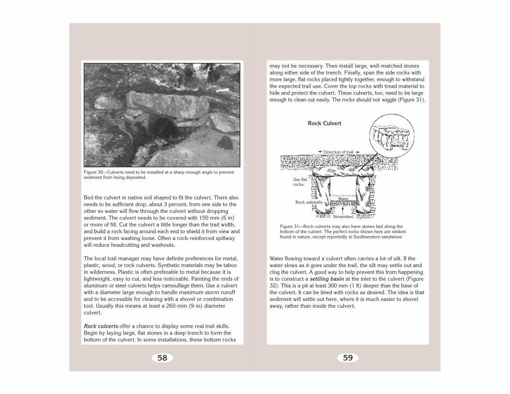
58
Figure 30—Culverts need to be installed at a sharp enough angle to preventsediment from being deposited.
Bed the culvert in native soil shaped to fit the culvert. There alsoneeds to be sufficient drop, about 3 percent, from one side to theother so water will flow through the culvert without droppingsediment. The culvert needs to be covered with 150 mm (6 in)or more of fill. Cut the culvert a little longer than the trail width,and build a rock facing around each end to shield it from view andprevent it from washing loose. Often a rock-reinforced spillwaywill reduce headcutting and washouts.
The local trail manager may have definite preferences for metal,plastic, wood, or rock culverts. Synthetic materials may be tabooin wilderness. Plastic is often preferable to metal because it islightweight, easy to cut, and less noticeable. Painting the ends ofaluminum or steel culverts helps camouflage them. Use a culvertwith a diameter large enough to handle maximum storm runoffand to be accessible for cleaning with a shovel or combinationtool. Usually this means at least a 260-mm (9-in) diameterculvert.
Rock culverts offer a chance to display some real trail skills.Begin by laying large, flat stones in a deep trench to form thebottom of the culvert. In some installations, these bottom rocks
59
Figure 31—Rock culverts may also have stones laid along thebottom of the culvert. The perfect rocks shown here are seldomfound in nature, except reportedly in Southwestern sandstone.
Streambed
Rock sidewalls
➛
Use flatrocks.
Water
Direction of trail
➛
➛
Rock Culvert
may not be necessary. Then install large, well-matched stonesalong either side of the trench. Finally, span the side rocks withmore large, flat rocks placed tightly together, enough to withstandthe expected trail use. Cover the top rocks with tread material tohide and protect the culvert. These culverts, too, need to be largeenough to clean out easily. The rocks should not wiggle (Figure 31).
Water flowing toward a culvert often carries a lot of silt. If thewater slows as it goes under the trail, the silt may settle out andclog the culvert. A good way to help prevent this from happeningis to construct a settling basin at the inlet to the culvert (Figure32). This is a pit at least 300 mm (1 ft) deeper than the base ofthe culvert. It can be lined with rocks as desired. The idea is thatsediment will settle out here, where it is much easier to shovelaway, rather than inside the culvert.

60
Geosynthetics
Geosynthetics are synthetic materials (usually made from hydro-carbons) that are used with soil or rock in many types ofconstruction. Geosynthetics can increase the effectiveness ofconstruction methods and offer some additional alternatives totraditional trail construction practices.
Geosynthetics perform three major functions: separation,reinforcement, and drainage. Geosynthetic materials include geo-textiles (construction fabrics), geonets, sheet drains, geogrids,and geocells. All these materials become a permanent part of thetrail, but must be covered with soil or rock to prevent deteriora-tion by ultraviolet light or damage by trail users.
Geotextiles (Figure 33) are the most widely used geosyntheticmaterial. Sometimes they are called construction fabrics. They aremade from long-lasting synthetic fibers bonded to form a fabric.
T R A I L T R E A D
Settling Basin
Rock
culvert
➛
Excavatedsettling basin
STRE
AM
FLOW
➛
Figure 32—Settling basins help prevent culvert clogging.
➛61
Figure 33—Felt-like geotextiles are easier to work with than heat-bonded, slit-film, or woven products that have a slick texture.
Geotextiles are often used in trail turnpike or causeway construc-tion. They serve as a barrier between the silty, mucky soil beneaththe fabric and the mineral, coarse-grained, or granular soil placedas tread material on top of the geotextile. The importance of sepa-ration cannot be overemphasized. It takes only about 20 percentsilt or clay before mineral soil takes on the characteristics of mud—and mud is certainly not what you want for your tread surface.Most geotextiles commonly used in road construction work fortrail turnpikes. The fabric should allow water to pass through it,but have openings of 0.3 mm or smaller to prevent silt frompassing through.
Geotextile is sensitive to ultraviolet light. It readily decomposeswhen exposed to sunlight. Unexposed, it lasts indefinitely. Alwaysstore unused geotextile in its original wrapper.
They are primarily used for separation and reinforcement over wet,unstable soils. They have the tensile strength needed to supportloads and can allow water, but not soil, to seep through. Nonpor-ous geotextiles can be used in drainage applications to interceptand divert ground water.

62
Figure 34—The net-like core of geonet allows drainage.
Sheet drains (Figure 35) are another form of composite madewith a drainage core and one or two layers of geotextile. The coreis usually made of a polyethylene sheet shaped like a thin eggcrate. The core provides an impermeable barrier unless it hasbeen perforated by the manufacturer. When used under the trailtread material, sheet drains provide separation, reinforcement,and drainage. Since they have greater bending strength than geo-textiles or geonets, less tread fill is often needed.
Sheet drains or geonets can be used as drainage cutoff walls(Figure 36). If the trail section is on a side slope where subsurfacewater saturates the uphill side of the trail, a cutoff wall can beconstructed to intercept surface and subsurface moisture, helpingto drain and stabilize the trail section.
Geonets or geonet composites (Figure 34) have a thin polyethy-lene drainage core that is covered on both sides with geotextile.They are used for all three functions—separation, reinforcement,and drainage. Since geonets have a core plus two layers of geo-textile, they provide more reinforcement than a single layer ofgeotextile.
63
Figure 35—Sheet drains have a large cross section that provides significantdrainage capacity. If placed under the trail tread, orient the sheet drain with thegeotextile side on the bottom and the plastic core on top.
Directi
on of
Trav
elFill
material
Sheet drain or geonet. Geotextile side facesuphill to intercept seepage and is insertedinto the slot in the top of the collector pipe.
Seepage
Collector pipe
Large rocks
SURFACE
Outlet pipe orsheet drain
Figure 36—Sheet drain or geonet used to intercept seepage.
ORIGINAL
➛
➛
➛
➛
➛
Drainage Cut-Off Walls
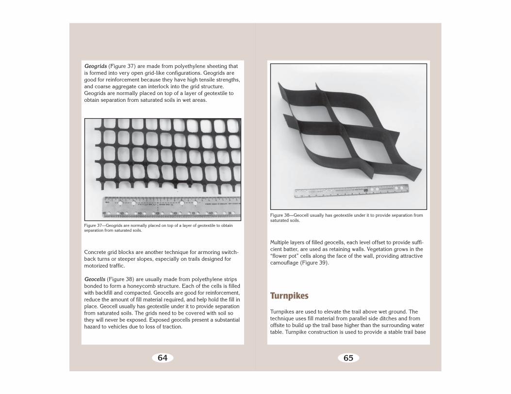
64
Figure 37—Geogrids are normally placed on top of a layer of geotextile to obtainseparation from saturated soils.
Geogrids (Figure 37) are made from polyethylene sheeting thatis formed into very open grid-like configurations. Geogrids aregood for reinforcement because they have high tensile strengths,and coarse aggregate can interlock into the grid structure.Geogrids are normally placed on top of a layer of geotextile toobtain separation from saturated soils in wet areas.
Concrete grid blocks are another technique for armoring switch-back turns or steeper slopes, especially on trails designed formotorized traffic.
Geocells (Figure 38) are usually made from polyethylene stripsbonded to form a honeycomb structure. Each of the cells is filledwith backfill and compacted. Geocells are good for reinforcement,reduce the amount of fill material required, and help hold the fill inplace. Geocell usually has geotextile under it to provide separationfrom saturated soils. The grids need to be covered with soil sothey will never be exposed. Exposed geocells present a substantialhazard to vehicles due to loss of traction.
65
Figure 38—Geocell usually has geotextile under it to provide separation fromsaturated soils.
Multiple layers of filled geocells, each level offset to provide suffi-cient batter, are used as retaining walls. Vegetation grows in the“flower pot” cells along the face of the wall, providing attractivecamouflage (Figure 39).
Turnpikes
Turnpikes are used to elevate the trail above wet ground. Thetechnique uses fill material from parallel side ditches and fromoffsite to build up the trail base higher than the surrounding watertable. Turnpike construction is used to provide a stable trail base

66
Figure 39—“Flower pot” retaining wall of geocells.
in areas of high water table and fair to well drained soils. Turnpikesare practical up to 10 percent trail grade (Figure 40).
Figure 40—Trail turnpike.
Slope
➛
➛
➛
Leadoffditch
Turnpike With Leadoff Ditch
67
A turnpike should be used primarily in flat areas with 0 to 20 percentsideslope where there is wet or boggy ground. The most importantconsideration is to lower the water level below the trail base andcarry the water under and away from the trail at frequent intervals.Turnpikes requires some degree of drainage. When the ground isso wet that grading work cannot be accomplished and drainage isnot possible, use puncheon surfacing instead. However, a turnpikeis easier and cheaper to build and may last longer than puncheon.A causeway is another alternative where ground water saturationis not a problem but a hardened tread is needed.
Begin your turnpike by clearing the site wide enough for the trailtread plus a ditch and retainer log or rocks on either side of thetrail tread. Rocks, stumps, and stobs that would protrude abovethe turnpike tread or cause large rips in geotextiles should beremoved or at least cut flush below the final base grade.
Ditch both sides of the trail to lower the water table. Install geo-textile or other geosynthetic materials and retainer rocks or logs.Geotextile and geogrid should go under any retainer rocks or logs(Figure 41). Lay the geotextile over the top with no excavation,then fill over with high quality fill. An alternative method, onethat not only provides for separation between good fill and claybut also keeps a layer of soil drier than the muck beneath, is calledencapsulation, or the sausage technique. Excavate 250 to 300mm (10 to 12 in) of muck from the middle of the turnpike. Laydown a roll of geotextile the length of the turnpike, wide enough
Underlying boggy soil
Ground line
Slope 1:1
➛
Mineral soil
Sideditch
Figure 41—Place geotextile under the retainer logs or rocks before staking.
Geotextile Placement
CROSS SECTION
➛➛
Rock retainer option
➛1 mMinimum crown 50 mm
➛
➛
➛
Wooden stakes
Log retainers150 to 200 mm
Geotextile Sideditch
➛
➛30
0m
m
➛
➛

68
Log retainers
➛ Wooden stakes
➛
Sideditch
➛
➛
Geotextile
➛
300-mm overlap
Underlying boggy soil
Ground lineSideditch
Rock retainer option
➛
➛
Sausage or Encapsulation Technique
CROSS SECTION
Figure 42—Sausage or encapsulation method.
Gravel or rock
to fold back over the top with a 300-mm (1-ft) overlap (Figure 42).Place 150 mm (6 in) of good fill, or even rocks, on top of thesingle layer of geotextile, then fold the geotextile back over thetop and continue to fill with tread material.
Rocks or logs can be used for retainers. Rocks last longer. If youuse logs, they should be at least 150 mm (6 in) in diameter andpeeled. Lay retainer logs in one continuous row along each edgeof the trail tread. The logs can be notched to join them, if desired.However, in some species notching may cause the logs to rotfaster (Figure 43).
Notched Retainer Log
Figure 43—Notched retainer log.
Notching
Spike
Notching
PEELED LOG
➛
➛
➛
69
Figure 44—Try this old Alaska trick if yourstakes tend to work up out of boggy ground.
Sharpen thebig end ofthe sapling.
Sapling Stake
Stak
e ap
prox
. 400
-mm
long
Stobs 50to 75 mm
Ground level
Anchor the logs with stakes or, better yet, large rocks along the out-side. Inside, the fill and surfacing hold the retainer logs (Figure 44).
Firm mineral soil; coarse-grained soils or granular material; orsmall, well-graded angular rock are needed for fill. Often it isnecessary to haul in gravel or other well-drained material tosurface the trail tread. If good soil is excavated from the ditch, itcan be used as fill. Fill the trail until the crown of the trail tread is50 mm (2 in) or a minimum of 2-percent grade above theretainers. It doesn’t hurt to overfill to begin with, as the fill willsettle.
Construct a dip, waterbar, or a drainage structure at each end ofthe turnpike where necessary to keep water from flowing onto thestructure. Keep the approaches as straight as possible comingonto a turnpike, to minimize the chance that stock or motorbikeusers will cut the corners and end up in the ditches.

70
Figure 45—Causeways create an elevated, hardened tread across seasonablywet areas.
Wall rocksDirt tread
Resodded old ruts Old ruts
Rocky fill
➛ ➛
➛
➛
➛
Causeways
Turnpike maintenance, especially recrowning, is particularlyimportant the year after construction; most of the soil settlingoccurs during the first year.
CausewaysA more environmentally friendly relative of the turnpike is thecauseway, essentially a turnpike without side ditches (Figure 45).Causeways filled with crushed rock have been successfully usedthroughout the Sierra Nevada and elsewhere to create an elevated,hardened tread across seasonally wet alpine meadows. Oftenmultiple parallel paths are restored and replaced with a singlecauseway. Causeways create less environmental impact thanturnpikes because ditches are not used and the water table is notlowered. The risk is that in highly saturated soils the causewaycould sink into the ground, a problem that geotextile can helpprevent.
71
Figure 46—Puncheon.
➛➛
Stringer
➛
Mud sill
Running planks
➛
Spacers
➛
Deck—plankshave approx.20-mm gaps
Curb or bull rail
➛
➛
600 mmminimum
Puncheon
Puncheon
Puncheon is a wooden walkway used to cross bogs or deepmuskeg, to bridge boulder fields, or to cross small streams. It canbe used where uneven terrain or lack of tread material makesturnpike construction impractical (Figure 46). Puncheon is alsopreferred over turnpike where firm, mineral soil cannot be easilyreached; puncheon can be supported on muddy surfaces betterthan turnpike, which requires effective drainage.
Puncheon resembles a short version of the familiar log stringertrail bridge. It consists of a deck or flooring made of sawn,treated timber or native logs placed on stringers to elevate thetrail across wet areas that are not easy to drain. Puncheon that isslightly elevated is termed surface puncheon. Puncheon placedflush with the wetland surface is known as subsurface puncheon.

72
Corduroy
Cover with soil
➛
Figure 47—Corduroy should be considered a temporary fix until a more perm- anent structure can be installed.
Sooner or later, you’ll probably hear the term, corduroy. Cordu-roy is basically a primitive type of puncheon. It consists of layingthree or more native logs on the ground as stringers with crosslogs laid side by side across the stringers and bound together withwire or nails (Figure 47). Corduroy should always be buried, withonly the tread exposed. Corduroy is notorious for not lasting verylong and consuming large amounts of material. It should only beused as a temporary measure.
Here’s how to build puncheon. First of all, the entire structuremust extend to solid mineral soil so soft spots do not develop ateither end. Approaches should be straight for at least 3 m (10 ft)coming up to a puncheon. Any curves either approaching or whileon the puncheon add to the risk of slipping, especially to stockand to mountain bike and motorcycle users.
To begin construction, install mud sills. These support the stringers.Mud sills can be made of native logs, treated posts, short treatedplanks, or precast concrete parking lot curb blocks. The mud sillsare laid in trenches at both ends of the area to be bridged at inter-vals of 1.8 to 3 m (6 to 10 ft) (Figure 48). They are approximatelytwo-thirds buried in firm ground. If firm footing is not available, userock and fill to solidify the bottom of the trench, increase the lengthof the sill log to give it better flotation, or use more sills for theneeded floatation. Enclosing rock and fill in geotextile minimizes
73
1.8 to 3.0 m apart
Stringer jointMud sills
Stringers
Tie stringer—place on double mudsill and drift pin to each mud sill.
TOP VIEW
Figure 48—Mud sill and stringer layout.
the amount of rock and fill required. For stability, especially inboggy terrain, the mud sills should be as long as practical up to2.5 m (8 ft).
Stringers made from 200-mm (8-in) peeled logs or treated timbersare set on top of the mud sills. They should be at least 3 m (10 ft)long and matched by length and diameter. Stringers also need tobe level with each other so the surface of the puncheon will belevel when the decking is added. Two stringers are sufficient forhiking trails, but for heavier uses, such as stock use, three arerecommended.
Notch the mud sills, if necessary, to stabilize the stringers and toeven out the top surfaces (Figure 49). To hold the stringers inplace, toenail spikes through the stringers to the mud sills or driveNumber 4 rebar (1⁄2 in) through holes in the stringers.
Next comes the decking. The thickness needs to be strong enoughfor the loads the structure will need to support. Lengths can be asnarrow as 460 mm (18 in) for a limited-duty puncheon for hikers.The decking should be 1.2 to 1.5 m (4 to 5 ft) long for puncheonsuitable for stock use.

74
Figure 49—When using logs, notch the mudsill—not the stringer.Do not notch them more than one third of their diameter.
B u r yMudsills
Stringers
Placementof log splice
L i n e
SIDE VIEW
Figure 50—Place decking planks on stringers to provide bearing for thefull width of the plank.
Do not spike decking to the center stringer, if you have one,because center spikes may work themselves up with time andbecome obstacles. Leave at least a 20-mm (3⁄4-in) gap betweendecking pieces to allow water to run off (Figure 50). Deckingshould be placed with tree growth rings curving down. Thisencourages water to run off rather than soak in and helps toprevent cupping.
Running planks are often added down the center for stock to walkon. Often the running planks are untreated because horseshoescut out the plank before wood has a chance to rot. Do not leavegaps between running planks because they can trap mountainbike or motorcycle wheels.
Steel drift pins, bolts, or rebar
25-mm spacersCurb logs
Notched mud sill logs
Decking
Runningplanks
Bury Line
75
Figure 51—Place a bulkhead or backing plate at each end of the puncheon.Approaches should have a rising grade so water will not run onto the structure.
Curb logs, also called bull rails, should be placed along each sideof the puncheon for the full length of the structure to keep trafficin the center. To provide for drainage, nail spacers between thecurb logs and the decking.
Finally, a bulkhead or backing plate needs to be put at each endof the structure to keep the stringers from contacting the soil(Figure 51). If the plate stays in place, do not spike it to the endsof the stringers. Spiking causes the stringers to rot faster.
In the rare case where puncheon is constructed on grades steeperthan 5 percent, treat the surface to reduce slipping. Use cleats,commercial fish netting, mineral roofing, or other surfacing.
Subsurface PuncheonSubsurface puncheon involves construction with the mud sill,stringers, and decking under the surface. This design depends oncontinual water saturation for preservation (Figure 52). Moisture,air, and wood are needed before wood can rot. Remove any oneof these and rot won’t occur. A good rule for reducing rot is tokeep the structure continually dry or continually wet. Totallysaturated wood will not rot because no air is present. Cover thesurface between the curb logs with a layer of gravel, wood chips,or soil to help keep everything wet.
Decking
Curb log
Spacer
Trail grade
Mineral
soil
Rock fill
Bulkhead
Stringer
Mud sill

76
Cover deck with gravel,soil, or wood chips.
Curb orbull rail
Figure 52—Subsurface puncheon with covered tread surfacing.
➛
➛
Deck
Mud sill
Curb or bull rail
➛
➛
SubsurfacePuncheon
With CoveredTread Surfacing
SurfacePuncheon
77
Crossing Streamsand Rivers
The Minimum Tool philosophy suggests that we get the job done with the least long-term impact while still meeting management objectives for an area. A few Minimum Tool questions for crossings are: • Do we really need a bridge here? Do we really need to be through here a month earlier each spring? • Will someone be killed or injured if we don’t provide an easier crossing? • Is this really the best place to cross this stream? • What alternatives do we have to cross this stream, including not crossing it at all? • Can we afford to do this? • What are the environmental and social conse- quences of a given type of crossing here? • Who will really care if we don’t build (or replace) a bridge? —It’s a wonderful thing to keep one’s feet dry. But it is expensive to keep feet dry in the backcountry.
Stream and river crossings present a chal-lenge to trail managers grappling with a mix of
user challenge, safety, convenience, cost, andesthetics. At one end of the use spectrum, a
bridge can allow people with disabilities, toddlers,and those new to the outdoors to experience the
trail with little risk. But bridges are expensive.Wilderness visitors who expect a challenge mayprefer a shallow stream ford. During high waterthese folks may opt for a tightrope walk across a
fallen log. Each kind of water crossing has consequences for therecreation experience and the lands being accessed. Choose wiselyfrom the spectrum of options before committing present andfuture resources to any given crossing.
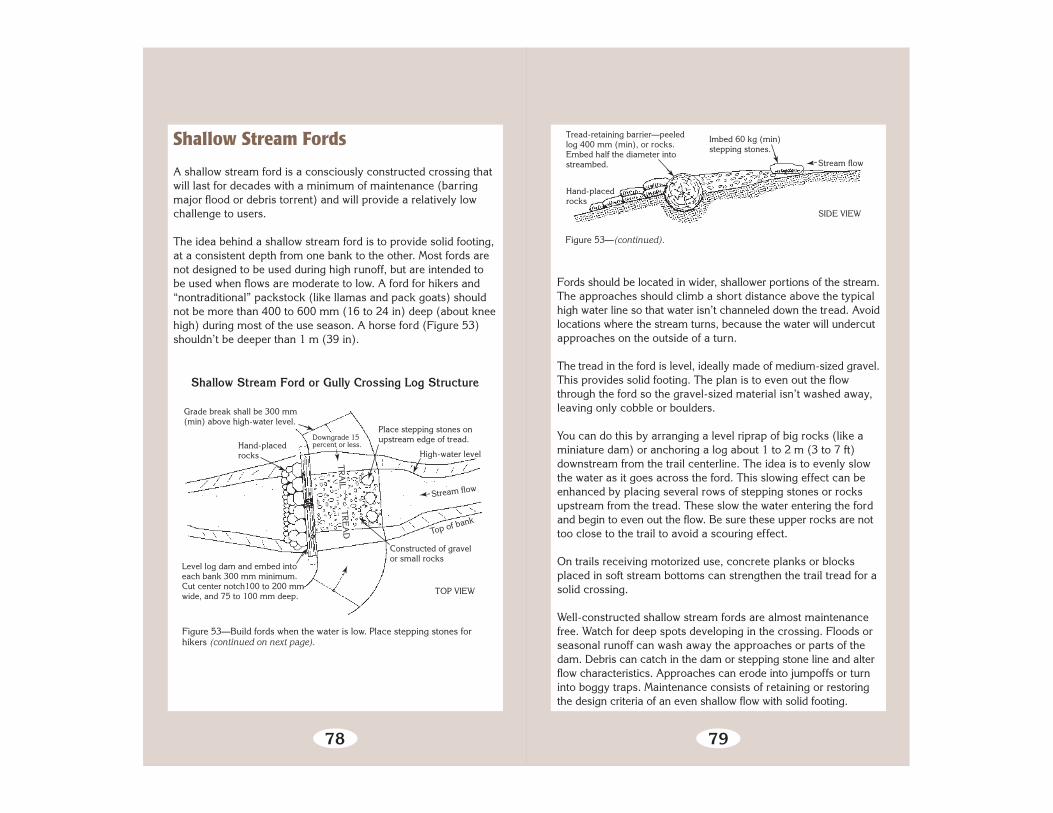
78
Shallow Stream Ford or Gully Crossing Log Structure
Grade break shall be 300 mm(min) above high-water level.
Hand-placedrocks
Place stepping stones onupstream edge of tread.
High-water level
Top of bank
Level log dam and embed intoeach bank 300 mm minimum.Cut center notch100 to 200 mmwide, and 75 to 100 mm deep.
Downgrade 15percent or less.
➛
➛
➛ ➛
➛
Stream flow➛
➛
➛
TOP VIEW
Figure 53—Build fords when the water is low. Place stepping stones forhikers (continued on next page).
Constructed of gravelor small rocks
➛
TRA
IL TRE
AD
Shallow Stream Fords
A shallow stream ford is a consciously constructed crossing thatwill last for decades with a minimum of maintenance (barringmajor flood or debris torrent) and will provide a relatively lowchallenge to users.
The idea behind a shallow stream ford is to provide solid footing,at a consistent depth from one bank to the other. Most fords arenot designed to be used during high runoff, but are intended tobe used when flows are moderate to low. A ford for hikers and“nontraditional” packstock (like llamas and pack goats) shouldnot be more than 400 to 600 mm (16 to 24 in) deep (about kneehigh) during most of the use season. A horse ford (Figure 53)shouldn’t be deeper than 1 m (39 in).
79
SIDE VIEW
Tread-retaining barrier—peeledlog 400 mm (min), or rocks.Embed half the diameter intostreambed.
Imbed 60 kg (min)stepping stones.
Hand-placedrocks
➛
➛ ➛
Stream flow
Figure 53—(continued).
Fords should be located in wider, shallower portions of the stream.The approaches should climb a short distance above the typicalhigh water line so that water isn’t channeled down the tread. Avoidlocations where the stream turns, because the water will undercutapproaches on the outside of a turn.
The tread in the ford is level, ideally made of medium-sized gravel.This provides solid footing. The plan is to even out the flowthrough the ford so the gravel-sized material isn’t washed away,leaving only cobble or boulders.
You can do this by arranging a level riprap of big rocks (like aminiature dam) or anchoring a log about 1 to 2 m (3 to 7 ft)downstream from the trail centerline. The idea is to evenly slowthe water as it goes across the ford. This slowing effect can beenhanced by placing several rows of stepping stones or rocksupstream from the tread. These slow the water entering the fordand begin to even out the flow. Be sure these upper rocks are nottoo close to the trail to avoid a scouring effect.
On trails receiving motorized use, concrete planks or blocksplaced in soft stream bottoms can strengthen the trail tread for asolid crossing.
Well-constructed shallow stream fords are almost maintenancefree. Watch for deep spots developing in the crossing. Floods orseasonal runoff can wash away the approaches or parts of thedam. Debris can catch in the dam or stepping stone line and alterflow characteristics. Approaches can erode into jumpoffs or turninto boggy traps. Maintenance consists of retaining or restoringthe design criteria of an even shallow flow with solid footing.

80
Figure 54—Typical log stringer trail bridge.
On national forests, all bridges require design approval from engineering before being constructed. A national standard trail bridge drawing is available, and some regions have standardized, approved designs for simple bridges.
Bridges
Bridges range from a simple foot log with handrails to multiplespan, suspended, and truss structures (Figure 54).
81
Figure 55—Log footbridge. The sill can be notched to accommodate the logs,not vice-versa.
On hiking trails, foot logs can be used to cross streams where safefords cannot be located or to provide access during periods ofhigh runoff. Constructed foot logs consist of a log, sills, and bulk-heads. The foot log should be level and well anchored. Notch thesill, not the log. The top surface should be hewn to provide awalking surface at least 250 mm (10 in) wide. Don’t let the logor rails touch the ground. Remove all bark from logs and poles(Figure 55).
If the foot log is associated with a shallow stream ford, be sure toposition the log upstream or well downstream of the ford. Logsimmediately below the crossing can trap travelers who lose theirfooting in the ford. If you have handrails, construct them accord-ing to plan. Improperly constructed handrails are a big liability,because they are not strong enough.
Choosing the materials for a bridge is not a simple process. Eventhe use of native material for a simple foot log has consequences.For example, most untreated logs of a durable wood (like coastalDouglas-fir) have a useful life of less than 20 years. Yet a log that

82
is big enough to support visitor traffic and winter snow loads maybe 100 years old. Plus, the typical bridge has three to four string-ers. Multiply this replacement-to-growth ratio by several replace-ment cycles and you see how it’s possible to create a slow motionclearcut around the bridge site.
Imported materials are often used to extend a bridge’s life.Pressure-treated wood, metal, concrete, wood laminates, and even“space-age” composites are being used in bridges. Many of thesematerials must be trucked or flown to a bridge site and the oldmaterials hauled out. All this is really expensive. Yet, these costsmay be less than the more frequent and more dangerous replace-ment of structures made from native materials. It’s possible tomix-and-match steel or other “unnatural but hidden” componentswith wood facing and decking to achieve a natural appearance.
Unless your bridge is preassembled and flown right onto a pre-pared set of abutments, you’ll end up moving heavy materialsaround the bridge site. Be careful to avoid trashing the site byallowing winch guylines and dragged logs to scar trees and disturbthe ground. The damage done in a moment can last for decades.
Other types of bridges include multiple span, suspended, andtruss structures (Figure 56). A two-plank-wide suspended footbridge with cable handrails is more complex than it looks. Mid-stream piers for multiple spans need to be professionally designedto support the design loads and withstand expected flood events.It does no one any good to win the National Primitive Skills Awardfor building a gigantic bridge by hand—only to have it fail a yearlater due to a design or construction oversight.
83
Figure 56—Suspension trail bridge typical of the Northern Rockies.
Bridges are expensive, so it makes sense to take good care ofthem. Check foot logs and bridges annually for problems. Loosedecking, planking, curbs, or handrails should be repaired assoon as possible. Clean debris and organic material from allexposed wood surfaces on the bridge or supporting structures.Structural members should be checked for shifting, loose, ormissing spikes or bolts. Approaches need to be well drained sowater does not run onto the bridge.
Report any of the following problems to a qualified bridge inspec-tor who can determine whether the bridge should remain open totraffic: rot; bent, broken, or disconnected steel members; largechecks, splits, crushed areas, or insect damage in wood members;permanent sag or excessive deflection; erosion around abutments;broken concrete; concrete with cracks larger than 3 mm (1⁄8 in);or exposed rebar.
All bridge structures need to be inspected by a qualified bridgeinspector at least every 4 years.

84
Special Structures
This section covers some of the more com-plex trail structures. Switchbacks, crib walls,
and similar structures are common in trailconstruction. They are often relatively expensive
and difficult to design and construct correctly.Inadequate maintenance greatly shortens their
useful lives. However, a well-designed, well-builttrail structure can last for decades and be quiteunobtrusive.
Special structures are more frequently used on low-challengetrails where easy, wide, and smooth grades are the managementgoal. The cost of building relatively easy trail into progressivelymore difficult terrain quickly becomes prohibitive (remember howmany fortunes and lives were poured into constructing railroads).Keep in mind the Minimum Tool philosophy and build only asmany structures as you absolutely need to reach your goal.
Switchbacks and climbing turns are used to reverse the directionof travel on hillsides and to gain elevation in a limited distance.What is the difference between the two? A climbing turn is areversal in direction that maintains the existing grade goingthrough the turn without a constructed landing. A switchback isalso a reversal in direction, but has a relatively level constructedlanding (Figure 57). Switchbacks usually involve special treatmentof the approaches, barriers, and drainages. They are used onsteeper terrain, usually steeper than 15 to 20 percent. Both ofthese turns take skill to locate and are relatively expensive toconstruct and maintain. Choosing when to use each one is notalways easy.
85
Climbing turns
➛
➛➛
➛
➛Switchbacks
CutbankTurning platform
Crib wall➛➛
➛
Figure 57—Climbing turns can be built on gentler slopes, usuallynot more than 15 to 20 percent. Switchbacks are needed onsteeper sites.
Switchbacks and Climbing Turns
Trail designers should make every effort to minimize the use ofthese turns. Planning carefully to avoid impassable or very difficultterrain reduces the need for switchbacks and climbing turns.
User psychology (human or animal) is more important to thesuccess of these structures than any other trail structure. The turnsmust be easier, more obvious, and more convenient than thealternatives. They work best when terrain or vegetation screensthe view of travelers coming down the upper approach toward theturn. Avoid building sets of these turns on open hillsides unlessthe terrain is very steep. It’s usually best not to build turns, or theconnecting legs of a series of turns, on or across a ridge. The localcritters have traveled directly up and down these ridges since thelast ice age. They are not going to understand why you are build-ing low hurdles in their path…and they will not be forced ontoyour trail and turns.
Try to avoid “stacking” a set of switchback turns on a patch ofhillside. Long legs between turns help reduce the temptation toshortcut. Staggering the turns so that all legs are not the samelength reduces the sense of artificiality. Keep the grade betweenturns as steep as the design challenge level allows. Remember,travelers will cut switchbacks when they feel it’s more convenient

86
Switchbacks
PREFERRED fewerlong switchbacks
LESS DESIRABLEfrequent short (orstacked) switchbacks
Figure 58—Long sections of trail between switchbacks are usuallybetter than short—fewer switchbacks will be needed, with fewerturns to shortcut.
to cut the turn rather than stay on the tread. The designer’s goalis to make travel on the trail more attractive than the shortcut(Figure 58).
87
Figure 59—Climbing turns continue the climb through the turn. They can beinsloped or outsloped.
Climbing Turn
Climbing Turns
Next to waterbars, climbing turns are the trail structure most oftenconstructed inappropriately. The usual problem is that a climbingturn is built (or attempted) on steep terrain where a switchbackis needed. A climbing turn is built on the slope surface, and whereit turns, it climbs at the same rate as the slope itself. If the slopeis 40 percent, the turn forces travelers to climb at 40 percent. Itis almost impossible to keep a climbing turn from eroding andbecoming increasingly difficult to travel if the slope is steeperthan 20 percent.
The advantages of climbing turns in appropriate terrain is that alarger radius turn (4 to 6 m, 13 to 20 ft) is relatively easy toconstruct. Trails that serve off-highway-vehicle traffic often useinsloped, or banked, climbing turns so that riders can keep upenough speed for control (Figure 59). Climbing turns are alsoeasier than switchbacks for packstock to negotiate. Climbing turnsare usually less expensive than switchbacks because much lessexcavation is required, and fill is not used.

88
The tread at each end of the turn will be full bench construction,matching that of the approaches. As the turn reaches the fall line,the amount of material excavated will decrease. In the turn, thetread will not require excavation other than that needed to reachmineral soil.
Guide structures should be placed along the inside edge of theturn. Temptation-reducing barricades can be added if necessary.The psychologically perfect place to build climbing turns isthrough dense brush or dog-hair thickets of trees. Be sure todesign grade dips into the approaches.
Switchbacks
Switchback turns are harder to build correctly, but retain stabletread on steeper terrain. Most switchbacks are constructed to amuch lower standard than is needed. The key to successfulswitchback construction is making an adequate excavation, usingappropriate structures to hold the fill in place, and building psych-ologically sound approaches.
Look for “natural” platforms when you are scouting for possibleswitchback locations. Use these for control points when locatingthe connecting tread. These will save you a lot of time later byreducing the amount of excavation and fill needed.
A switchback consists of two approaches, a landing or turn plat-form, a drain for the upper approach and platform, and guidestructures. The upper approach and the upper half of the turnplatform are excavated from the slope. Part of the lower approachand the lower half of the turn are constructed on fill (Figure 60).
The approaches are the place where most of the trouble withswitchback turns start. The approaches should be designed forthe primary user group. In general, the last 20 m (65 ft) to the
89
Switchback
Figure 60—Switchback with a radial turning platform.
Landing orturning platform
➛
turn should be as steep as the desired challenge level will allow.This grade should be smoothly eased to match that of the turn inthe last 2 to 3 m (6.5 to 10 ft).
Do not “flatten” the grade 20 m (65 ft) before the turn. If any-thing, steepen the approach grades to foster the sense that theswitchback is the most convenient way of gaining or losingaltitude. There is absolutely nothing as infuriating as walking anearly flat grade to a distant switchback turn while looking severalmeters over the edge at the nearly flat grade headed the otherdirection. You can build a Maginot Line of barricades and still notprevent people, packstock, and wildlife from cutting your switch-back. The only exception is a trail designed primarily for wheeledvehicles. The flatter approach makes control easier.
As the upper approach nears the turn, a grade dip should beinstalled. The tread below this point should be insloped until thehalfway point in the turn. Both sides of this trench should be back-sloped to an angle appropriate for the local soil. As the turn is
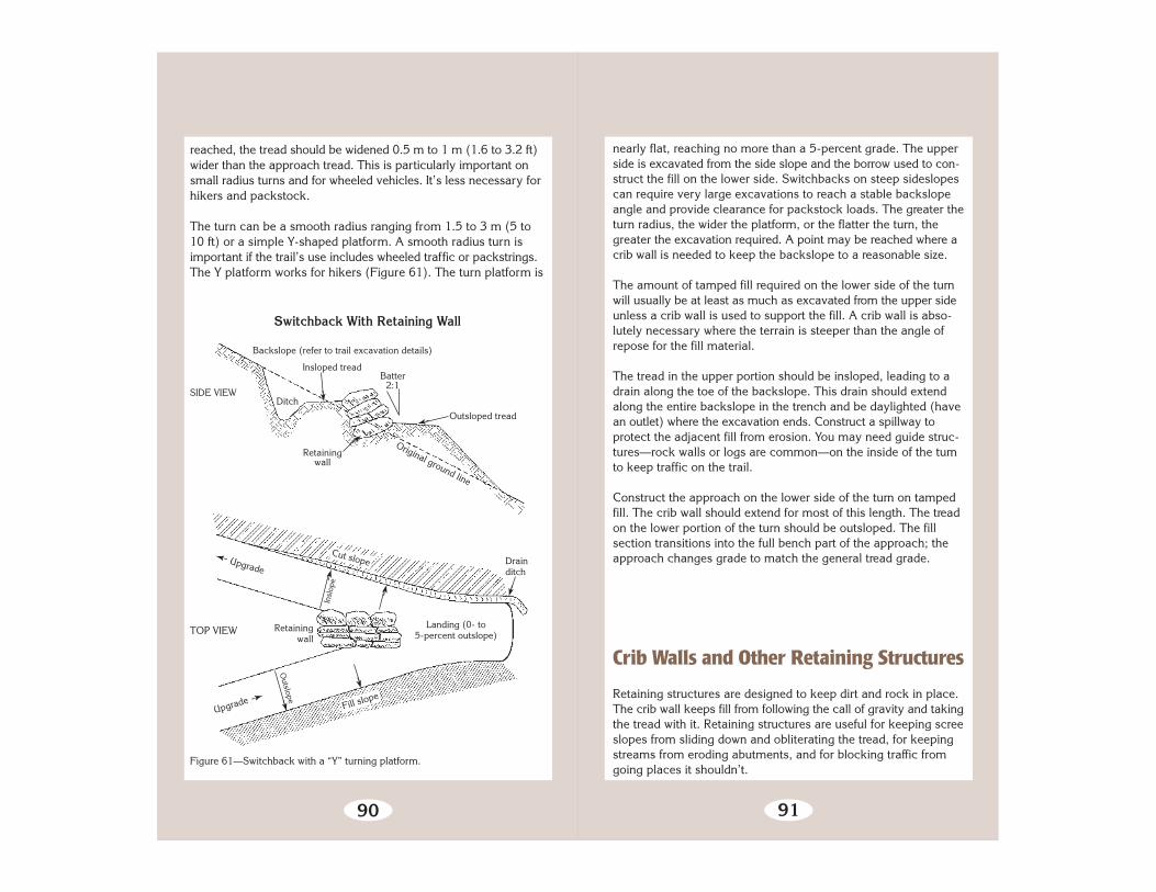
90
Figure 61—Switchback with a “Y” turning platform.
Switchback With Retaining Wall
SIDE VIEW
TOP VIEW
Backslope (refer to trail excavation details)
Insloped tread
Retainingwall
Ditch
Batter2:1
Outsloped tread
Original ground line
➛
➛
➛
➛
Upgrade
Insl
ope
Drainditch
Landing (0- to5-percent outslope)
Retainingwall
Upgrade
Outslope
Cut slope
Fill slope
➛
➛
➛
➛
reached, the tread should be widened 0.5 m to 1 m (1.6 to 3.2 ft)wider than the approach tread. This is particularly important onsmall radius turns and for wheeled vehicles. It’s less necessary forhikers and packstock.
The turn can be a smooth radius ranging from 1.5 to 3 m (5 to10 ft) or a simple Y-shaped platform. A smooth radius turn isimportant if the trail’s use includes wheeled traffic or packstrings.The Y platform works for hikers (Figure 61). The turn platform is
➛
➛91
nearly flat, reaching no more than a 5-percent grade. The upperside is excavated from the side slope and the borrow used to con-struct the fill on the lower side. Switchbacks on steep sideslopescan require very large excavations to reach a stable backslopeangle and provide clearance for packstock loads. The greater theturn radius, the wider the platform, or the flatter the turn, thegreater the excavation required. A point may be reached where acrib wall is needed to keep the backslope to a reasonable size.
The amount of tamped fill required on the lower side of the turnwill usually be at least as much as excavated from the upper sideunless a crib wall is used to support the fill. A crib wall is abso-lutely necessary where the terrain is steeper than the angle ofrepose for the fill material.
The tread in the upper portion should be insloped, leading to adrain along the toe of the backslope. This drain should extendalong the entire backslope in the trench and be daylighted (havean outlet) where the excavation ends. Construct a spillway toprotect the adjacent fill from erosion. You may need guide struc-tures—rock walls or logs are common—on the inside of the turnto keep traffic on the trail.
Construct the approach on the lower side of the turn on tampedfill. The crib wall should extend for most of this length. The treadon the lower portion of the turn should be outsloped. The fillsection transitions into the full bench part of the approach; theapproach changes grade to match the general tread grade.
Crib Walls and Other Retaining Structures
Retaining structures are designed to keep dirt and rock in place.The crib wall keeps fill from following the call of gravity and takingthe tread with it. Retaining structures are useful for keeping screeslopes from sliding down and obliterating the tread, for keepingstreams from eroding abutments, and for blocking traffic fromgoing places it shouldn’t.

92
Crib Wall
2.5 m (max) spacing
Face logs
Filler logs
15 mm drift pinsto penetrate threelogs (min)
LOOKING INTO HILLSIDE
➛
➛
➛
➛
➛
➛Direction of travel
➛
Figure 62—The characteristics of a crib wall. Treated logs are recommended(continued on next page).
The most common retaining structure is the crib wall. “Crib” isused primarily to keep compacted fill in place. Well-built crib isthe most stable kind of uncemented retaining structure (exceptperhaps wire gabion).
Construct wood crib by interlocking logs or beams, pinned ornotched (if logs) at the joints. Lay sill logs at right angles to thedirection of travel and alternate tiers of face logs and header logs(Figure 62). Each successive tier is set to provide enough batterto resist creep pressure from the slope and to reduce pressure onthe face logs from the fill. The ends of the header logs are seatedagainst the backslope of the excavation for stability. As fill istamped in place, filler logs are placed inside the structure to plugthe spaces between the face logs, and are held in place by the fill.Outslope the tread to keep water from saturating the fill and exca-vation. Use guide structures to keep traffic off the edge.
Wood crib is also used to construct piers for bridges and to holdrock fill for abutments. Wood crib is easier to build than rock crib-bing, but is less durable, especially in environments visited by rotor fire. Be sure to select rot-resistant logs if using native materials.
93
Trail bed
Notched rear logs
Unnotched sill logs
Unnotched filler logs
Notched header logs
SIDE VIEW
Trail tread
➛
➛
➛
➛
➛
➛
Figure 62—(continued).
Notchedface logs
Batter
Crib Wall
Rock or crib retaining walls are used when a sturdy wall is neededto contain compacted fill or to hold an excavation wall in place.Rock retaining walls are also called “dry masonry” because nomortar is used between stones. Rock, when available on site, ispreferred over logs.
To build a rock wall, excavate a footing in soil or to solid rock. Thefooting should be insloped to match the designed batter angle anddeep enough to support the foundation tier of stones (these areusually the largest stones in the wall) for the full width of the tread.Ideally, the footing is dug so that the foundation tier is embeddedfor the full thickness of the stones (Figure 63).
Ideally, the stones should weigh at least 20 kg (45 lb). At least halfof the stones should weigh more than 60 kg (130 lb). The idealstone is rectangular with flat surfaces on all sides. The worst stoneto use is rounded like river rock.

94
In reality, you have to use the rock available. Small crib walls can be successfully con- structed from smaller rocks. The key is the foundation platform and the batter. Remember to save some big rocks for the top course where you need them for capstones. A final point—most rock can be improved with a few good blows from a rock hammer. Placing the rock on dirt rather than another rock before striking will help ensure it breaks where you want it to.
Figure 63—Rock placement and batter is critical on the first courses.
Crib Wall Construction
Prepare a footing insolid earth or rock.
Use large rock forheaders. Alwaysplace long, narrowstones into the wall—never parallel to it.
T R A I L T R E A D ➛
➛
The batter should range from 2:1 to 4:1 (Figure 64). Factors determining this angle include the size and regularity of the rock, the depth of header stones, and the steep- ness and stability of the slope. At batter angles steeper than 4:1 or so, cement, or internal anchors (or both) may be needed for stability.
On short walls, it may be possible to constructthe entire structure starting upon a single keystone. The keystoneis laid into the footing and successive tiers are laid. Each tier’sface stones overlap the gaps between stones in the next lower tier.Each face tier includes tie or header stones that overlap the gapsbetween face stones and those deeper in the wall. The foundation
95
➛
Figure 64—Terms used to describe crib walls.
Crib Wall Terminology
Backfill: Mineralsoil and/or small rock.
Cap stone: Rock withsufficient mass and/or shape
to provide a stable top course.
Tie stone or header rock: Rock that islonger to extend or “tie” the wall into the
backfill.
Foundation course: The bottom layer of rock thatprovides a stable and insloped base—usually the
largest rocks.
Batter: Theamount thatthe wallleans intothe hillside.
Outslope
➛
➛
➛
➛
tier (or the keystone) should be insloped slightly and rest on theexcavated surface, not on fill. Each successive face tier shouldbe staggered slightly into the hill to create the desired amount ofbatter. Header stones should also be used to tie deeper stones tothose closer to the face. This is particularly important if the wallwidens in cross section as it gains height.
Stones in each successive tier should be set so they have at leastthree points of good contact with the stones below. Good contactis defined as no wobble or shifting under a load without relying onshims (or chinking) to eliminate rocking. Shims are prone toshifting and should not be used to establish contact, especiallyon the face of the wall, where they can fall out. Backfill andtamp as you build.
Other forms of retaining walls include gabion and variations of wetmasonry. Gabion is a series of wire baskets filled with rock. Thebaskets are wired together in tiers and can be effective where nosuitable source of crib stone is available. Gabion is more artificiallooking than crib (in the eyes of traditionalists at any rate), andmay have a shorter ‘lifespan,’ depending on the type of wire usedand the climate.

96
Figure 65—Step and run stairs in Alaska (plank boardwalk in foreground).
Steps
Steps and stairways are used to gain a lot of elevation in a shortdistance. Steps are common on steep hiking trails in New Englandand elsewhere, less common (but not unheard of) on westerntrails used by horses and mules. Wooden steps of all configura-tions are common in coastal Alaska (Figure 65).
Sometimes steps are used in an existing trail to fix a problemcaused by poor trail location or design. The result often is out ofcharacter with the desired experience and esthetics of the trail.Before you construct steps, make sure they are consistent withthe expectations of those the trail is designed to serve.
Your goal is to design the height (rise) and depth (run) of the stepsto match the level of challenge desired. Steps are harder to nego-tiate as the rise increases. The difficulty also increases as thesteps are closer together. Yet, as the trail becomes steeper, thestep must either be higher or the distance between steps must be
97
shorter. Steps can be built into a trail that traverses the slope.This allows the traveler to gain elevation rapidly, without the scarysteepness of a stairway.
The components of a step are: the rise, the run, a landing oneasier grades, and often retainer logs (Figure 66). The rise is thevertical distance gained at the face of each step. The run is thedistance from the edge of one step to the base of the next step’sface. The landing is the extension of the run above the step. Instructures where the landing is composed of tamped fill material,retainer logs are used to retain the fill.
Log trenchedone half of thelog diameter
RunSoil tread
➛
Overlap one third of the surface area
➛
➛ ➛
Rise Outslope2 to 5 percent
Outslope2 to 5 percent
Rebar
Level-hewn tread➛
➛
Overlapping Rock Stairway
Rock Riser Stairway
Log Riser Stairway
Figure 66—Common types of steps (continued on next page).

Figure 67—A general rule of thumb for stairs: Twice theriser plus the tread should equal 635 to 686 mm (25 to27 in).
Stair Proportions
98
Riprap Stairway
Figure 66—(continued).
Hikers, especially backpackers, generally don’t like steps and willwalk alongside them if there is any opportunity. The steps need tobe comfortable to climb or they won’t be used. This means keepingthe rise a reasonable 150 to 200 mm (6 to 8 in) and the run longenough to hold a hiker’s entire foot rather than just their toe(Figure 67). It’s helpful to armor the sides of steps with rocks toencourage users to stay on the steps.
200
mm
(8 in
)
250 mm(10 in)
Example— Twice riser.... 400 mm (16 in) Run..................250 mm (10 in) Total 650 mm (26 in)
99
In more primitive settings, you don’t need a uniform flight of stepsas long as the route is obvious and there is solid tread at eachstepping point. In the Sierra, a cross between cobblestones andstairs, locally called riprap, is commonly used for this purpose.Elsewhere, riprap refers to rock forming a loose retaining wall.
The most important area of the step is usually in the run. This iswhere most traffic steps as it climbs. If the step is composed ofsomething like a board on edge with fill behind it, then the trafficwill step onto the landing. Almost all foot traffic descending thestep will walk off the edge of the step. The top of the step (andlanding) should be stable and provide secure footing. The edge ofthe step should be solid and durable. The face of each step shouldnot contain a batter that creates a “face run” of over 50 mm (2 in)from top to bottom. This is particularly important as the rise ofthe step increases.
If the stairway climbs straight up the hill, each step should beslightly crowned to drain water to the edges or slightly sloped toone side. When the trail traverses a slope, each step and landingshould be slightly outsloped. Water should not be allowed todescend long lengths of a set of steps or to collect on or behinda step on the landing. A drain dip where the trail approaches thetop of the steps is a good idea.
Build stairways from the bottom up, at a break in the grade. Themost common mistake is to start part way up a grade. If you doso, the trail will wash out below the stairs (Figure 68). The
➛
Start the first step atthe break in grade.
The tendency is tostart up here.
Step Construction
➛
Figure 68—Begin laying steps at the bottom of a grade rather than midway.

100
bottom stair should be constructed on a solid, excavated footing.If it is constructed on top of exposed rock, it should be well pinnedto the footing. Each successive stair is placed atop the previousstair. Wood stairs are usually pinned to each other and into thefooting. Dry masonry rock stairs usually rely on the contact withthe stair below and with the footing to provide stability.
Steps with landings are a bit harder to secure in place becausethe stairs do not overlap. Each step can either be placed in anexcavated footing and the material below the rise removed toform the landing of the next lower step. This is usually the moststable arrangement. Or the step can be secured on the surfaceand fill used to form a landing behind it. The material used toprovide the rise does double duty as a retaining structure whenthe landing consists of tamped fill. These steps must be seatedwell to prevent them from being dislodged by traffic. For stockuse, landings should be long enough to hold all four of theanimal’s feet.
Individual steps can be placed at any point in a trail. They are use-ful for retaining tread material in rocky pitches or to protect treeroots. Single steps installed midslope usually become high-stepobstacles on stock trails or where there is heavy traffic or erosion.
In all steps, the key is to use the largest material possible and toseat it as deeply as possible. Rocks should be massive and rec-tangular. On steps that traverse a slope, it helps to seat the upperend of the step material in footings excavated into the slope.
Maintaining Special Structures
Maintaining climbing turns and switchbacks requires working onthe tread, maintaining drainage, and doing any necessary workon retaining walls, guide structures, and barricades. The treadshould be insloped or outsloped as necessary, slough should beremoved to return the tread to design width, and tread obstaclesshould be removed.
101
Retaining walls should be carefully checked for shifting, bulges,or loose structural material. Make sure that all the footings areprotected from erosion. Guide structures should be secure. Checkturn barricades for effectiveness and rebuild as necessary.
Remember, these special structures are relatively expensive anddeserve careful attention to protect the investment.
Some special tactics include the use of:
• Internal anchors for increasing the stability of retaining walls.• Precision blasting to obtain sufficient sized footings in rock.• Power tamping equipment to strengthen fill.• Cable systems for moving large rock or timbers to retaining
wall locations.
The best way to learn how to build these structures is to seeksomeone who designs and builds well thought-out switchbacks,climbing turns, or walls. Have that expert conduct a seminar foryour crew or actually participate in the construction.

102
Signing
Trail signing comes in two forms. Trailheadand junction signs are used to identify trail
names, directions, destinations, and distances.Reassurance markers are used to mark the trail
corridor when the tread may be difficult to follow.
Signing is typically used at trailheads to identifythe trailhead and the trails there. At some locations,destinations accessed by these trails and the dis-tances to the destinations will be displayed. (See
STANDARDS FOR FOREST SERVICE SIGNS & POSTERS, (EM 7100-15),especially parts 2.7, 5.1.1, and 5.4-5.11). Signs are also used atsystem trail junctions (and road crossings) to identify each trail byname and indicate its direction. Signs are also used to identifyfeatures, destinations, and occasionally, regulations, warnings, orclosures.
Reassurance Markers include cut or painted blazes on trees;wood, plastic, or metal marker tags; marker posts; and cairns.These markers are used to help travelers identify the trail corridorwhen the tread is indistinct, the ground is covered with snow, orwhen the path is confused by multiple trails or obscured byweather such as dense fog. National Trails are usually markedperiodically with specially designed marker tags. Signs or reassur-ance markers can be used to identify a system trail at confusingjunctions.
The amount of signing or reassurance marking depends primarilyon the planned level of challenge for the user. Low challenge trailswill typically be signed with destinations and distances. The trailwill usually be so obvious that reassurance marking is necessaryonly at points of confusion. As the desired opportunity for chal-lenge rises, the amount of information given by signs usually
103
The amount and type of signing and reassur- ance markers should be detailed in a sign plan for the area you are working in. Consistent with the plan, signing and marking should be esthetically appro- priate, the minimum necessary, visible, in useful locations, and well main- tained.
drops to trail identification and direction. You may find specialguidelines for wilderness. Reassurance markers are more usefulas the tread becomes more difficult to identify and follow.
Installing Signs
Trail signs are made of a variety of materials; the most typical is a routed wood sign. Signs are usually mounted on posts or trees. Signs in rocky areas should be mounted on a post seated in an excavated hole or supported by a well- constructed cairn.
Wooden posts may be obtained onsite or hauled in. Onsite(native) material is usually less expensive, but may have a shorteruseful life. Native material usually looks less artificial; it is usuallychosen in primitive settings. Purchased posts should usually bepressure treated. Their longer lifespan will offset the initialpurchasing and transportation costs. Round posts appear lessartificial than square posts and provide more options for customalignment of signs at trail junctions. Posts should be at least 150mm (6 inches) in diameter.
Well-placed signs are easily readable, yet far enough from thetread to provide clearance for normal traffic. In deep snowcountry, try to locate the post in relatively flat surroundings toreduce the effects of snow creep.
Spikes or lag screws can be used at the base of the post toimprove anchoring (Figure 69). Seat the post in the hole and holdit vertical while you drop a few rocks into the hole to secure it.Tamp these rocks with a rockbar or tool handle to jam them into

104
P O
S T
Figure 69—The key to placing solid posts is to tamp the rock and soilwith a rockbar as you fill the hole.
Compressed soil
Rock laid andtamped tight
➛
➛
➛Anchor bolt
Signpost Installation
Hole 500 to 600 mm deep
place. Continue to place rocks and dirt in the hole, tamping asyou go. Top off the hole with mounded soil to accommodatesettling and prevent puddling around the post.
In rocky areas or very soft soils (such as adjacent to a turnpikestructure), sign posts can be supported by a cairn. Horizontallyplaced spikes or lag screws should be used at the base foranchors. Chinking with smaller rocks help tighten the post againstthe cairn stones.
Signs should have holes predrilled so they can be attached to thepost. Level each sign and secure it to the post using plated lagscrews. Plated hardware reduces rust stains on the sign. Platedwashers should be used between the head of the screw and thesign face to reduce the potential for the sign to pull over the screw.In areas where sign theft is a problem, use specialty theft-preventionhardware. The bottom edge of signs should be set about 1.5 m(60 in) above tread level. The sign’s top edge should be 50 mm(2 in) below the top of the post. Where snow loads are a problem,the post can be notched and the signs seated full depth. Treatedposts will be susceptible to rotting where they are notched, sothey should be spot treated with preservative.
105
Use caution when mounting signs to trees. The sign should beobvious to travelers and legible from the tread. If mounting ontrees doesn’t meet these conditions, use a post instead. Mountsigns to trees with plated lag screws and plated washers, ratherthan spikes. This way, the sign can be periodically loosened toaccommodate tree growth. Leave a gap between the sign andthe tree to allow for the growth.
Installing Reassurance Markers
Reassurance markers are used only where the trail is not obvious.If the tread is obvious during the regular use season, these markersaren’t needed. Reassurance markers may be useful if a trail is hardto follow because the tread is indistinct, regularly covered withsnow during part of the normal use season, or if weather conditions(such as fog), make the trail hard to distinguish at times. Reassur-ance markers are also useful at junctions with nonsystem (informal)trails, or where multiple trails cause confusion.
Place markers carefully. They should be clearly visible from anypoint where the trail could be lost. This is a judgment call, andoften controversial, based on the challenge level served by thetrail and the conditions along it. Higher challenge trails need fewermarkers; lower challenge trails may need more. If part of a trailhas reassurance markers, all of it should be marked.
Each marker location should be flagged before installation andchecked for visibility in the desired direction of travel. Each loca-tion should be marked in both directions (on both sides of thesame tree) so there is no question whether or not the marker isofficial. This second marker might not be as usefully sited forthose traveling the opposite direction. The marking decisionsshould be based on traffic traveling in both directions. Be conserv-ative with markers. It’s better to improve tread visibility than torely on markers except on high challenge trails where tread mayfrequently not be visible at all.

106
Top blaze:100 mm wideand 50 mm tall.
Vertical spacebetween blazes:50 to 100 mm.
Lower blaze:100 mm wideand 200 mm tall.
Distance from theground: 1.5 mfor foot trails.
Figure 70—Blaze trees on both sides. Cut no deeper than necessary for clear visibility.
Blazes Markertags orblazers
Blazes andMarker Tags
1.5
m m
inim
um
➛
➛
The classic reassurance marker is a blaze cut on a tree. Thestandard Forest Service blaze should always be used to differen-tiate it from the freeform blazes and antler rubbings that appearon nonsystem trails (Figure 70). Different types of blazes may beused on some specially designated trails, such as the AppalachianTrail. Cut blazes carefully as a mistake can’t be repaired. If a blazeis consistently buried by snow during part of the use season, theblaze can be cut higher on the tree, but not so high that it becomesdifficult to locate from the tread. Blazes are no longer cut on treesin many parts of the country.
Next up the scale of reassurance markers is a routed or brandedwooden trail marker, which is routed or branded onto wood andmounted on the tree. Routing and scorching is much moredurable than branding. A variation of these markers are routedor branded national trail markers. Check with your local trailmanager and review your forest plan to learn what’s appropriatein designated wilderness—there is much variability nationwide.
107
Painted blazes are sometimes used for visibility. Beabsolutely sure to use a template of a size specified in yourtrail management plan. Always use the specified color. Don’tlet just anyone start painting blazes. They should not bepainted on rocks.
Marker tags or “blazers” are used when higher visibility isdesired and esthetic considerations are not as high. Mostcommon are colored diamonds of either plastic or metal.Various colors are used. For trails used by mountain bikes oroff-highway vehicles, the tags should be reflective. Thesetags should be mounted on trees with aluminum nails. Allow12 mm (1⁄2 inch) or so behind the tag for additional treegrowth. Directional arrows, where appro-priate, should beplaced in a similar fashion. Blazers can also be mounted onwooden or fiberglass posts.
Cairns are used in open areas where low visibility or snowcover makes following the tread difficult or where the tread isrocky and indistinct. Two or three stones piled one on top ofthe other, “rock ducks,” are no substitute for cairns andshould be scattered at every opportunity. Cairns are similarin construction to rock crib and consist of circular tiers ofstones (Figure 71).
Make the base wide enough to provide enough batter forstability. In really deep snow country, it might be necessaryto add a long guide pole in the center as the cairn is built. Ananchored pipe can be built into the center of the cairn so apole can be replaced or removed each summer.
Cairns should be spaced closely enough that during typicalepisodes of poor visibility (such as dense fog) the next cairnis visible in either direction from any given cairn. Cairnsshould be placed on small rises (not in swales). If cairns areused in areas of large talus, use a 2-m (6.5-ft) guide pole inthe center to differentiate the cairn from adjacent piles ofrock. The best time to decide where to place cairns is during aday with poor visibility.

108
Cairns
Figure 71—Two- or three-stone “rock ducks” are not a substitute forcairns and should not be built.
TOP VIEW
Use flat stones andoverlap the joints.
Slope stones inward.
Do not use smallstones wedgedin cracks forstructuralsupport.
Use largestones tobuild thebase.
Overlap all joints.
Pack the centerwith rubble.
SIDE VIEW
ROCK DUCK
900
mm
750 mm minimum
➛
➛
➛
➛
Guide poles are used in settings similar to cairns. They are mostuseful in snowfield crossings to keep traffic in the vicinity of theburied tread. Guide poles should be long enough to extend about2 m (6.5 ft) above the top of the snowpack during the typicaluse season. Guide poles should be at least 100 mm (4 in) indiameter. They should be sturdy enough to withstand early
Illustrations courtesyof the AppalachianMountain Club’s TrailAdopter Handbook.
109
season storms before the snow can support them and to with-stand pressures from snow creep later in the season. Avoidplacing guide poles in avalanche paths. Don’t mark trails forwinter travel if they cross known avalanche paths.
Guide poles are also used in large meadows where tall grassesmake cairns hard to spot, or where there is too little stone forcairns.
Sign and Marker Maintenance
Sign maintenance consists of remounting loose or fallen signs,repairing or replacing signs, and resetting or replacing leaning,damaged, rotting, or missing posts.
If the sign is missing, a replacement sign should be orderedand installed. Check out the probable cause of the loss. If itwas theft, consider using theft-resistant hardware to mountthe replacement. If the sign was eaten by wildlife, look at lesspalatable materials. If the weather or natural events munchedthe sign, consider stronger materials, a different location, oran alternate strategy for mounting.
For signs mounted on trees, you may need to loosen the lagscrews slightly to give the tree growing room. If the sign is on apost, check to make sure that it is snugly attached. Replacerotting posts. Don’t just try to get through “one more season.”
Check with your manager for guidelines when signs should bereplaced due to bullet holes, chipped paint, missing or illegibleletters, incorrect information, cracked boards, splintered mount-ing holes, or missing pieces. At each candidate sign, considerthe consequences of not repairing or replacing deficient signing.Take some photos to help portray the situation.
Cut blazes may, on rare occasions, need to be “freshened.” Ifa blaze has “healed” to the point where it doesn’t resemblean official blaze, it may be carefully recut.

110
Blazers and marker tags should be checked for continued useful-ness. If the tread is more obvious than when these markers wereoriginally installed, consider removing some. If folks are gettinglost, restore morevisible tread, moveexisting reassurancemarkers to morevisible locations, oradd a few markerswhere they will bemost effective.
Remove all signingand reassurancemarking that doesn’tfit the plan for thearea.
Before-and-after photos are useful for documenting what is happening to signing in the field and for document- ing how new signing looks before the forces of nature (and visitors) resume work. A good sign inventory with photos makes ordering replacements for missing or completely trashed signs much easier.
111
NaturalizingAbandoned Trails
Figure 72—Candidate trail for a causeway or rerouting, combined withnaturalization.
Naturalizing abandoned trails requires asmuch attention and planning as constructingnew trail.
The goal is to reduce the impact human trailshave on the landscape. Simple restoration may
consist of blocking new shortcuts and allowing thevegetation to recover. Complex restoration projectsinclude obliterating the trail, recontouring, andplanting genetically appropriate species. Careful
monitoring and followup are necessary to ensure that almost allevidence of the trail is gone. Thus, restoration ranges from simpleand relatively inexpensive to complex and costly (Figure 72).
Past practices of trail abandonment have left permanent scars onthe land. If you’ve worked in trails awhile, you probably know ofabandoned trails that had a few logs and rocks dragged into the

112
Figure 73—Abandoned trails need to be blocked off effectively, and withsensitivity.
tread and trenches. Decades later, those same trails are stillvisible, still eroding, still ugly, and sometimes, still carryingvisitor traffic!
Naturalization strategies include: closure, stabilization, recontour-ing, revegetation, and monitoring. Restoration needs to be care-fully planned. The consequences of each strategy should beexamined. Consult with a hydrologist and soil and plant specialistswhen planning a naturalization project.
Each abandoned trail should be closed (Figure 73). This is truewhether an entire trail is abandoned or a segment with multipletrails is being narrowed back to one tread. If the trail is notblocked to prevent further use, the trail may persist indefinitely.Closure is particularly important if stabilization and revegetationare being attempted. The abandoned tread should be blocked toall traffic, recontoured, and disguised to prevent users frombeing tempted to take it. This work should be accomplished forall segments visible from trails that remain open.
113
Check Dams
150 to 250 mm typical
Trail
125 mm (min)
Use 300-mm-diameter logs or100- x 300-mm dimensional lumber.
50- x 450-mm stakes. Use 16dringshank or barbed nails.
16- x 600-mm rebar. Drive flush with top oflog.
SIDE VIEW
Tread
➛
➛
➛
➛
➛
➛
Figure 74—Check dams or retainer bars allow soil to rebuild on eroded trails(continued on next page).
Stabilize abandoned tread to prevent further erosion. This will pro-mote natural revegetation in some instances. Trails break naturaldrainage patterns and collect and concentrate surface water flows.Restoring the natural contour of the slope reestablishes the localdrainage patterns and reduces the likelihood of erosion. Recon-touring usually eliminates any temptation to use the old trail andfacilitates revegetation efforts. Pull any fillslope material backinto the cut and use additional material to rebuild the slope, ifnecessary.
Remove culverts and replace them with ditches. Loosen the soilwith hand tools, stock and harrow, or heavy equipment to speedrevegetation.
Check Dams
Check dams are used on pieces of abandoned, trenched tread toarrest further erosion and to hold material placed during site res-toration. Sometimes check dams are appropriate for trails inactive use. Check dams are intended to slow and hold surfacewater long enough to deposit transported sediment. They shouldbe used with drainage structures to reduce overall erosion fromthe abandoned tread (Figure 74).

114
Embed logs,rocks, ordimensionallumber aminimum of300 mm intoundisturbedbank.
TOP VIEW
Figure 74—(continued).
Check Dams
Check dams are best used as holding structures for fill used torecontour the old tread. The material used in the dam should beseated in an excavated footing that extends into the sides of thetrench. As material behind the dam naturally builds up, succes-sive levels can be added to the dam with enough batter to offerstability against the pressure of the fill. The top of the dam shouldbe level or slightly higher than the trench walls. For watertight-ness, chinking and tamped fill should be used to complete theuphill face of the dam. Fill is then added behind the dam to finishthe process. It generally takes a long time for these trenches tofill up. Most never do. If they do, add fill below the dam to finishthe process.
Spacing between dams depends on the steepness of the old gradeand the degree of restoration desired. If the check dam is intendedonly to slow down erosion, then relatively wide spacing is suffi-cient (every 20 m (65 ft) on a 25-percent grade). If the intent isfor half of the old trench to be filled back in, the bottom of eachdam should be level with the top of the next lower dam. On steepergrades the dams need to be closer together. If the intent is toapproach complete recontouring of the trench, the dams should
115
be closer still, especially on grades above 25 percent. A point ofdimin-ishing returns is reached on grades above 40 percent.Check dams would have to be built right on top of each other toretain soil at the full depth of the trench.
Revegetation
Revegetation can be accomplished passively or actively. Passiverevegetation allows surrounding vegetation to colonize the aban-doned trail. This works when erosion has been stopped, adequateprecipitation occurs, and adjacent vegetation spreads and growsrapidly. Active revegetation ranges from transplanting onsite veg-etation to importing genetically appropriate seed or propagatedplants. Successful revegetation almost never happens in a singleseason. Plan carefully for best results.
There are no cookbook answers for returning abandoned trails totheir natural condition. Each site should be evaluated for itspotential to regrow and heal. On sites that are moist and relativelyflat, it may be possible to block off the trail and allow rehabilita-tion to proceed naturally. Dry, steep sites will take a lot of work.

116
Tools
Many specialized trail tools can make yourtrail experience either enjoyable or miserable,
depending on whether you have the right toolat the right time and know how to use it. Here
are some basics; check the references for moredetailed information.
Right up front, here are some key rules:
• Your most important tool is your brain—use it.• Always use proper personal protective equipment like hardhats,
gloves, and safety glasses. Make sure a job hazard analysishas been approved and a safety plan is being followed. Selectthe right tools for the job. Carefully inspect them before youuse them. Make sure handles are sound, smooth, and straight,and heads are tight.
• Pace yourself. Take rest breaks, and keep your mind on yourwork. Trade off on tools occasionally for relief from repetitivestresses.
• Keep cutting tools sharp. A dull tool makes your work harderand more dangerous.
• Before you start, clear away any brush or limbs that might catcha swinging tool unexpectedly.
• Posture is important. Stand comfortably in balance. Adjust yourstance and tool grip continually to prevent slipping and to avoidglancing blows. Be especially careful when working in wet,slippery conditions.
• Be thinking about the consequences of every move. If you areworking with a rock or log, think ahead so you are not standingin the wrong place when it moves. Be ready to toss your toolaside and jump free. Avoid cutting toward any part of your body,and watch out for your coworkers. Use skill, not brute force.
117
• When carrying, loading, or storing a cutting tool, cover the bladewith a sheath to protect both the sharp edge and yourself. Invehicles, make sure tools are fastened down.
• Maintain at least 3 m (10 ft) between workers as a safe operatingdistance when using individual chopping and cutting tools.
• Carry sharp tools at your downhill side. Grasp the handle atabout the balance point with the sharpened blade forward anddown. If you fall, throw the tool clear.
• At the job site, lay tools temporarily against a stump or downedlog with blades directed away from passing workers. Never sinkdouble bit axes, Pulaskis, mattocks, or similar double-edgedtools into the ground or in stumps where they become danger-ous obstacles.
Tools for Measuring
Clinometers. A clinometer is a simple, yet very useful, instru-ment for measuring grades. Most clinometers have two scales, oneindicating percent of slope, the other showing degrees. Percentslope, the relationship between the amount of elevational rise ordrop over a horizontal distance, is the most commonly usedmeasure. Don’t confuse percent and degree readings. It is easyto do! Expressed as an equation:
Percent of Grade = Rise x 100 percentRun
A section of trail 30 m (100 ft) long with 3 m (10 ft) of eleva-tional difference would be a 10-percent grade.
Tape Measures. Get a tape measure that has metric units.Another good idea is to mark off commonly used measurementson your tools. Know the length of your feet, arms, fingers, andother handy rulers as a ready reference on the trail. Calibrate thelength of your pace over a known course so you can easily esti-mate longer distances.

118
Global Positioning Systems. Quite a few trail surveyors arefinding GPS to be the hot ticket for accurate trail location, inven-tory, and contract preparation. Real-time correction is no longernecessary, and prices have fallen. GPS is becoming the norm fora lot of trail location work.
Tools for Sawing
Crosscut Saws.Crosscut saws maybe asymmetric orsymmetric. Asym-metric crosscut sawsrequire only onesawyer. They are heavier sothey can be pushed and pulled without buckling. Most asymmetricsaws are bucking saws. Symmetric crosscut saws, those designedfor a sawyer at either end, follow two basic patterns. Felling cross-cuts are light, flexible, and have concave backs that conformeasily to the arc of the cut and the sawyer’s arm. The narroweddistance between the teeth and back helps sawyers wedge thecut quickly. Bucking crosscuts have straight backs and areheavier and stiffer than felling saws.
When carrying a saw, lay it flat across one shoulder with a guardcovering the teeth. The teeth need to face away from the neck.You can also tie the saw into a narrow V (not a sharp C, for carry-ing. Don’t store it this way.
Use blade guards made of sections of rubber-lined firehose slitlengthwise. Velcro fasteners facilitate removal. Don’t leave a wetguard on a saw.
A sharp crosscut is a pleasure to operate, but a dull or incorrectlyfiled saw is a source of endless frustration, hence its reputation asa misery whip. Never sharpen without a saw vise and knowledge.Field sharpening ruins crosscut saws.
Felling crosscut
Bucking crosscut
119
Bow saw
To prevent tree sap from binding the crosscut blade in the cut,lightly lubricate the blade with citrus-based solvent. Kerosene isno longer recommended because it is highly flammable and is ahealth hazard if it is absorbed through the skin, or inhaled. Lightlycoat the blade with the light machine oil to prevent rust.
For more information, Warren Miller’s classic, THE CROSSCUT SAW
MANUAL (revised 1988) is available from the Missoula Technologyand Development Center.
Bow Saws. Bow saws are useful for clearing small downfall andfor limbing. They consist of a tubular steel frame designed toaccept replaceable blades. The blades detach by loosening a wingnut or releasing a throw clamp.
The teeth are needle sharp, so wear gloveswhen sawing and keep your hands clear
of the cut and the blade. Carry bowsaws by your side with the bladepointed down. Cover the bladewith plastic blade guards or smalldiameter fire hose secured withVelcro fasteners. Always carryspare parts and plenty of replace-ment blades.
Chain Saws. A chain saw will make short work of your cuttingtasks—but it is not for wilderness use. Specialized instruction andcertification is required, so make sure you have it before operatinga chain saw.
Pruning Saws. Pruning sawsare useful for limbing, somebrushing, and removing small downfall,especially where space is limited and cutting isdifficult. Folding pruning saws are handy.
Folding pruning saw

120
Double-bit ax
Single-bit ax
Tools for Chopping
Axes. Axes are of two basic types—single or doublebit. Single-bit axes have one cutting edge opposite a flatface. Double-bit axes have two symmetrically opposed cuttingedges. One edge is maintained at razor sharpness and the otheris usually somewhat duller as a result of chopping around rocksor dirt. Mark the duller edge with a spot of paint.
Before chopping, check for adequate swing clearance.Remove underbrush and overhanging branches
that might interfere with your swing. Besure your footing is stable and secure.
Chop only when you are clear ofother workers.
Stand comfortably with your weight evenly distributed and bothfeet planted shoulder-width apart. Measure the correct distanceto stand from the cut by holding the handle near the end andstretching your arms out toward the cut. You should be able totouch the blade to the cut.
Begin chopping by sliding your forward hand within 150 mm (6 in)of the head. As you swing, your forward hand slides back downthe handle to the other hand. Just after impact, give the handle aslight twist to pop severed wood out of the cut.
Proficiency with axes requirespractice. Inexperienced userswith dull axes may causeserious accidents. In general,the force of the swing is not asimportant as accurate place-ment. Always chop away fromyour body. Stand so aglancing blow will not strikeyou. If you must cut toward
yourself, “choke up” on the handle with both hands and use shor tswings for more control.
Twicediameter
of log
Equal todiameter
of log➛
➛
➛
➛
121
Pulaski
Combi tool
McLeod
Tools for Grubbing
Pulaskis. The Pulaski combines an axand a grub hoe into one multipurposefirefighting tool. It isn’t as good as a hoeor mattock for grubbing, nor as good asan ax for chopping. It is a popular trailtool because it is widely available andeasier to carry than single-purpose tools.
When using the hoe end, stand bent atthe waist with your back straight and parallel to the ground,
knees flexed, and one foot slightly forward. Hold thehandle with both hands so the head is at an angle to
your body, and use short, smooth, shallow swings.Let the hoe hit the ground on its corner. Use the
ax end to chop large roots after the dirt hasbeen cleared by the hoe. Always wear safety
goggles while grubbing to guard againstflying chips of rock and dirt.
Carry the Pulaski at your side; grip the handle firmly near thehead, and point the ax end away from your body and down.Sharpen the cutting edge like an ax. When sharpening the hoe,maintain the existing inside edge bevel. Never sharpen the top ofthe hoe.
Combination Tools. The combination or combi tool is basicallya military entrenching tool on a long handle,developed for firefighting. It serves as alight-duty shovel and scraper.
McLeods. TheMcLeod combinesa heavy-duty rake with a large, sturdy hoe. McLeods work wellfor constructing trails through light soils and vegetationor for reestablishing tread along sloughed side cuts.They are inefficient in rocky orunusually brushy areas.

122
Fire rake
Pick
Pickmattock
Cuttermattock
Fire Rake (Council Tool). The fire rake is another fire tool usedwidely for tread work, especially in the East.
Picks. Pick heads have apointed tip for breakinghard rock by forcing anatural seam. Theyalso have a chisel tipfor breaking softermaterials.
Work the pick like a Pulaski hoewith short, deliberate, downwardstrokes. Avoid raising the pick overhead while swinging. Alwayswear safety goggles while using a pick to guard against flyingrock chips.
Use a grinder or mill bastard file to sharpen pointed tips to 3-mm(1⁄8-inch) squares. When sharpening chisel tips, maintain thefactory bevel.
Mattocks. The pick mattock is often recommended as thestandard tool for trail work. For many applications, it is much
better than a Pulaski. It has a pointed tip forbreaking rocks and a grubbing blade for
working softer materials. The grub-bing blade may also be used to cutroots or remove small stumps.Moreover, with the edge of the tool,you can tamp dirt and loose rocks orsmooth a new tread.
Maintain good cutting edges onmattocks. Sharpen grubbing blades to
maintain a 35° edge bevel on the underside. Sharpen pick endslike you would a pick, and maintain factory bevels on cutterblades.
123
Adze hoe
Hazel hoe
Grub hoe
Stump grinder
Hoes. Use an adzehoe, grub hoe, orhazel hoe to breaksod clumps whenconstructing newtrail or leveling anexisting trail tread.These hoes are alsouseful in heavyduff. They generallywork better than aPulaski.
Stump Grinders. If you have lots of stumps to remove, considerbuying or renting a gasoline-powered stump grinder. Theseportable grinders are powered by a chain saw motor and havecarbide teeth that can be resharpened or replaced. They grindthrough a stump in much less time and with a whole lot lessfrustration than would be needed to dig it out.
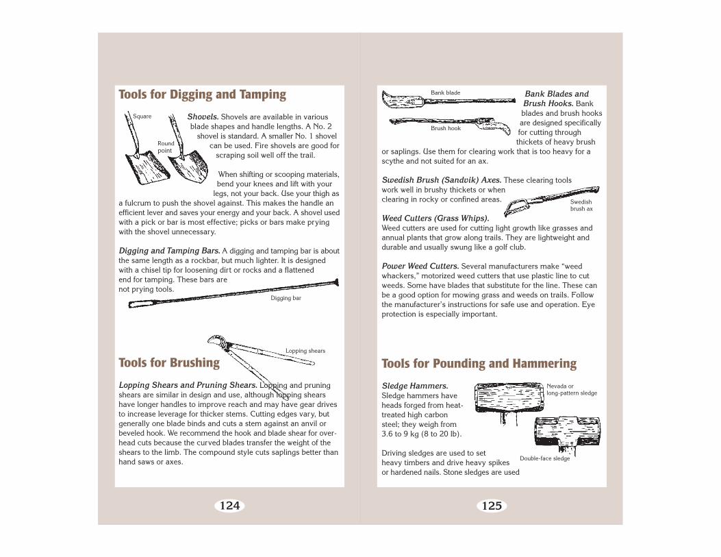
124
Square
Roundpoint
Digging bar
Tools for Digging and Tamping
Shovels. Shovels are available in variousblade shapes and handle lengths. A No. 2
shovel is standard. A smaller No. 1 shovelcan be used. Fire shovels are good for
scraping soil well off the trail.
When shifting or scooping materials,bend your knees and lift with your
legs, not your back. Use your thigh asa fulcrum to push the shovel against. This makes the handle anefficient lever and saves your energy and your back. A shovel usedwith a pick or bar is most effective; picks or bars make pryingwith the shovel unnecessary.
Digging and Tamping Bars. A digging and tamping bar is aboutthe same length as a rockbar, but much lighter. It is designedwith a chisel tip for loosening dirt or rocks and a flattenedend for tamping. These bars arenot prying tools.
Tools for Brushing
Lopping Shears and Pruning Shears. Lopping and pruningshears are similar in design and use, although lopping shearshave longer handles to improve reach and may have gear drivesto increase leverage for thicker stems. Cutting edges vary, butgenerally one blade binds and cuts a stem against an anvil orbeveled hook. We recommend the hook and blade shear for over-head cuts because the curved blades transfer the weight of theshears to the limb. The compound style cuts saplings better thanhand saws or axes.
Lopping shears
125
Swedishbrush ax
Bank blade
Brush hook
Double-face sledge
Nevada orlong-pattern sledge
Bank Blades andBrush Hooks. Bankblades and brush hooksare designed specificallyfor cutting throughthickets of heavy brush
or saplings. Use them for clearing work that is too heavy for ascythe and not suited for an ax.
Swedish Brush (Sandvik) Axes. These clearing toolswork well in brushy thickets or whenclearing in rocky or confined areas.
Weed Cutters (Grass Whips).Weed cutters are used for cutting light growth like grasses andannual plants that grow along trails. They are lightweight anddurable and usually swung like a golf club.
Power Weed Cutters. Several manufacturers make “weedwhackers,” motorized weed cutters that use plastic line to cutweeds. Some have blades that substitute for the line. These canbe a good option for mowing grass and weeds on trails. Followthe manufacturer’s instructions for safe use and operation. Eyeprotection is especially important.
Tools for Pounding and Hammering
Sledge Hammers.Sledge hammers haveheads forged from heat-treated high carbonsteel; they weigh from3.6 to 9 kg (8 to 20 lb).
Driving sledges are used to setheavy timbers and drive heavy spikesor hardened nails. Stone sledges are used

126
Stonesledge
Singlejack
Double jack
Rockbar
Bar
Fulcrum
➛
to break boulders or concrete. Because of differencesin tempering, these tools are not interchangeable.
Hand-Drilling Hammers. Hand-drilling ham-mers are used to drill steel into rock or to drivewedges and feathers into cracks or drilled
holes. There are two types of hand-drillinghammers—single jacks and double jacks.
For more information on hand drilling, readHAND DRILLING AND BREAKING ROCK (1984).
Tools forLifting andHauling
Rockbars. Use a rockbar (also called pry bar) for prying large,heavy objects. These bars are heavy duty. They have a chisel tipon one end and a rounded handle on the other.
Place the tip of the chisel under an object to be moved. Wedge alog or rock between the bar and the ground to act as a fulcrum.Press the handle down with your body weight over your palms.Never straddle the bar when prying. When the object raises asmuch as the bite will allow, block it and use a larger fulcrum orshorter bite on the same fulcrum to raise it further. You will gainproficiency with practice.
127
A motorized carrier.
Block and Tackles. A block and tackle is a set of pulley blocksand ropes used for hoisting or hauling. They come in differentstyles, sizes, and capacities.
Ratchet Winches. Ratchet winches (also called come-alongs) areuseful for pulling stumps and for moving large rocks and logs.These winches offer mechanical advantage—the Grip Hoist is aspecialized winching system that provides a mechanical advantageof 30:1 or more. You really need to know what you are doing withthese tools to use them safely and effectively.
Wheelbarrows. Wheelbarrows with pneumatic tires are best asthese tires can be inflated or deflated to roll easily on differentsurfaces.
Motorized Carriers. If your budget and regulations allow, considera motorized carrier. These come in various configurations andtypically feature a dump body. A trailer pulled behind an all-terrain vehicle is another possibility. MTDC has construction plansfor a gravel trailer.

128
ATV trailer (plans available from MTDC).
Packstock bag.
Packstock Bagsand Panniers.Fabric bags or hard-sided panniers withdrop bottoms workwell for carrying trailconstruction mater-ials on packstock.MTDC has a designavailable for fabricbags. Off-the-shelffruit picking bags alsowork well as a low-cost alternative foroccasional or lightduty use. Commercialaluminum droppanniers are a moreexpensive option.
129
Canvas coal bag.
Peavy
Cant hook
Canvas Bags.Heavy-dutycanvas bagssold to carrycoal are greatfor dirt, smallrocks, andmulch.
Cant Hooks andPeavys. Cant hooks andpeavys afford leverage formoving or rotating logs.To roll a heavy log, use aseries of short bites with
the hook and maintain yourprogress by quickly resetting it.
Catch the log with the hook hanging ontop of the log. Rotate the log using the
leverage of the handle, working the tool like aratchet. Moving large logs may require several hooks
working together. Avoid taking large bites; a heavy log will rollback and pin the handle before the hook can be reset.

130
Room for two persons on each side
Log carrier
Bark spud
Drawknife
Log Carriers. Log carriers enable teams of workers to movelogs. The tool hooks the log, allowing persons on either side ofthe handle to drag it. Several carriers could allow four or morepersons to carry a large log.
Tools for Peeling and Shaping
Bark Spuds (Peeling Spuds). Use a bark spud to peel greenlogs. Position the log about hip high. Hold the tool firmly with both
hands and push the dished blade lengthwise alongthe log under the bark. Always pry away from
your body. Three sharpened edges make thistool unusually hazardous to use and
transport.
Drawknives. A drawknife worksbest to peel dry logs. Position
the log about waist high,and grasp both handles
so the beveled edgeof the blade facesthe log. Begin each
stroke with arms extended and pull the tool toward you whilekeeping even pressure on the blade. Keep fingers clear of bladecorners.
131
Carpenter’s adze
Edgebevel
Blade of cutting-edge tool
Blade bevel
Carpenter’s Adzes (Cutting Adzes).This tool trims and shapes logs intohewed timbers or flattened logs. To usea cutting adze, stand astride or on topof the log to be hewed. Grip the handlewith both hands and swing it with shortstrokes in a pendulum motion alongthe log. Use your thigh asa stop for your arm andto control the depth of thecut. When standing on alog and swinging, stand onthe heel of your forwardfoot, toe pointed up.
A square-tapered eye and handle end allows the head to tightenwhen swung, but also allows its removal for carrying andsharpening. Some adzes may have a small set screw to furthersecure handles to heads. An adze needs to be razor sharp to work.Never use this tool for grubbing.
Tools for Sharpening
About Sharpening—Inspect all tools before use. Sharpeningmakes tools last longer. A small scratch that is ignored couldlead to a serious crack ornick in the blade.
Use a file or grindstone toremove metal from the edge.If there are no visible nicks, atouchup with a whetstone willrestore a keen cutting edge. In these instances, you need onlyrestore the edge bevel. Whetting the edge removes very smallbits of metal from the blade and causes the remaining metal toburr slightly on the cutting edge. This burr is called a feather, orwire edge. Remove this weak strip by honing the edge on the

132
Correct
Wrong
Blade bevels
File
HandleKnuckle guard(old linen hose)
other side. The correctly honed edge issharp, does not have a wire edge, anddoes not reflect light or show a sharpen-ing line. Wear gloves when sharpeningcutting edges.
Restoring the blade bevel requires coarsergrinding tools to reshape worn cuttingblades. Reshape blades with hand files, sand-stone wheels, or electric grinders. Removevisible nicks by grinding the metal back onthe blade. Remember that the correct bladebevel must be maintained. If the shape can’tbe maintained, have a blacksmith reconditionthe tool head or discard it.
If a cutting edge is nicked from a rock, it often is work hardened.A file will skip over these spots and create an uneven edge. Usea whetstone to reduce the work-hardened area, then resumefiling. Alternate the two until the file cuts smoothly over theentire length of the edge.
Files. Files come in single or double, curved, or rasp cuts.Single-cut files have one series of parallel teeth angled 60° to 80°from the edge; they are used for finishing work. Doublecut files have two series of parallel teeth set at a 45°angle to each other; they are used for restoringshape. Curved files are used for shaping softmetals. Rasp cut files are used for wood.
Files are measured from the point to the heel,excluding the tange (the tip used to attach ahandle). Length determines the coarsenessof files. There are generally three degreesof file coarseness: bastard, second cut,and smooth. The bastard will be thecoarsest file available for different cutsof files of the same length. A 254-mm(10-inch) mill bastard file is good forall-around tool sharpening.
133
Before filing, fit the file with a handle and knuckle guard. Alwayswear gloves on both hands to prevent cuts from the sharpenededge. Secure the tool so both hands are free for filing. Use thelargest file you can, depending on the size, nature, and workablestroke length of the job. Remember that files are designed to cutin one direction only. Apply even pressure on the push stroke, thenlift the file up and off the tool while returning for another pass.
Store or transport files so they are not thrown together. Protectthem from other tools. An old piece of fire hose sewn shut on oneend makes a great file holder for several files, a guard, and handle.A hand-tool sharpening gauge that gives you all the correct anglescan be ordered from the General Services Administration (GSA).

134
Appendix
Selected Trail Constructionand Maintenance References
Birchard, William, Jr.; Proudman, Robert D. 2000. Appalachian trail design, construction,
and maintenance: 2nd ed. Harpers Ferry, WV:Appalachian Trail Conference. ISBN 1-917953-72-X. 237 p. (Copies for sale at 888–287–8673.)
Birkby, Robert C. 1996. Lightly on the land: the SCA manual ofbackcountry work skills, Student Conservation Association.The Mountaineers. ISBN 0-89886-491-7. 272 p. (Copies forsale at 603–543–1700.)
Demrow, Carl; Salisbury, David. 1998. The complete guide to trailbuilding and maintenance. 3d ed. Boston, MA: AppalachianMountain Club. 1SBN 1-878239-54-6. 246 p. (Copies for saleat 800–262–4455.)
Didier, Steve; Herzberg, Diane. 1996. Stock-drawn equipmentfor trail work. Tech. Rep. 9623-2802-MTDC. Missoula, MT:U.S. Department of Agriculture, Forest Service, MissoulaTechnology and Development Center. 22 p. (Copies availableat 406–329–3978.)
Gonzales, Ralph. 1996. Mechanized trail equipment. Tech. Rep.9623-1207-SDTDC. San Dimas, CA: U.S. Department of Agri-culture, Forest Service, San Dimas Technology and Develop-ment Center. 85 p. (Copies available at 909–599–1267, ext.113.)
135
Griswold, Stephen S. 1996. A handbook on trail building andmaintenance. 5th ed. Three Rivers, CA: U.S. Department ofInterior, National Park Service. Sequoia Natural HistoryAssociation. 136 p. (Copies for sale at 559–565–3758.)
Hallman, Richard. 1988 (rev. 1997). Handtools for trail work. Gen.Tech. Rep. 8823-2601-MTDC. Missoula, MT: U.S. Department ofAgriculture, Forest Service, Missoula Technology and Develop-ment Center. 26 p. (Copies available at 406–329–3978.)
Meyer, Kevin G. 2002. Managing degraded off-highway vehicletrails in wet, unstable, and sensitive environments. Tech Rep.0223-2821-MTDC. Missoula, MT: U.S. Department of Agri-culture, Forest Service, Missoula Technology and DevelopmentCenter. 48 p. (Copies available at 406–329–3978.)
Miller, Warren. 1988 (rev 2003). Crosscut saw manual. Gen. Tech.Rep. 7771-2508-MTDC. Missoula, MT: U.S. Department ofAgriculture, Forest Service, Missoula Technology and Develop-ment Center. 28 p. (Copies available at 406–329–3978.)
Monlux, Steve; Vachowski, Brian. 2000. Geosynthetics for trailsin wet areas: 2000 edition. Gen. Tech. Rep. 0023-2838-MTDC. Missoula, MT: U.S. Department of Agriculture, ForestService, Missoula Technology and Development Center. 18 p.(Copies available at 406–329–3978.)
Mrkich, Dale; Oltman, J. 1984. Hand drilling and breaking rockfor wilderness trail maintenance. Gen. Tech. Rep. 8423-2602-MTDC. Missoula, MT: U.S. Department of Agriculture, ForestService, Missoula Technology and Development Center. 26 p.(Copies available at 406–329–3978.)
Steinholtz, Robert T.; Vachowski, Brian. 2001. Wetland trail designand construction. Tech. Rep. 0123-2833-MTDC. Missoula, MT:U.S. Department of Agriculture, Forest Service, MissoulaTechnology and Development Center. 82 p. (Copies availableat 406–329–3978.)

136 137
U.S. Department of Agriculture, Forest Service. 1999. Health andsafety code handbook. FSH 6709.11. Washington, DC: U.S.Department of Agriculture, Forest Service. 503 p. (Referencecopies available at Forest Service offices nationwide.)
U.S. Department of Agriculture, Forest Service. 1985. Trailsmanagement handbook. FSH 2309.18. Washington, DC: U.S.Department of Agriculture, Forest Service. (Reference copiesavailable at Forest Service offices nationwide.)
U.S. Department of Agriculture, Forest Service. 1992. Surfacewater control techniques for trail maintenance (video).Missoula, MT: U.S. Department of Agriculture, Forest Service,Missoula Technology and Development Center. 27 minutes.(Copies available at 406–329–3978.)
U.S. Department of Agriculture, Forest Service. 1994. Trails inwet areas—turnpike and puncheon construction (video).Missoula, MT: U.S. Department of Agriculture, Forest Service,Missoula Technology and Development Center. 22 minutes.(Copies available at 406–329–3978.)
U.S. Department of Agriculture, Forest Service. 1995. Basic trailmaintenance (video). Missoula, MT: U.S. Department of Agri-culture, Forest Service, Missoula Technology and DevelopmentCenter. 28 minutes. (Copies available at 406–329–3978.)
U.S. Department of Agriculture, Forest Service. 1996. Standardspecifications for construction and maintenance of trails. EM-7720-103. Washington, DC: U.S. Department of Agriculture,Forest Service. ISBN 0-16-048802-8. 108 p. GovernmentPrinting Office 001-001-00661-1 $6.50.
U.S. Department of Agriculture, Forest Service. 1997. Standarddrawings for construction and maintenance of trails. EM-7720-104. Washington, DC: U.S. Department of Agriculture, ForestService (Reference copies available at Forest Service officesnationwide.)
U.S. Department of Agriculture, Forest Service. 1998.Handtoolsfor trail work, part 1 and part 2 (videos). Missoula, MT: U.S.Department of Agriculture, Forest Service, Missoula Technologyand Development Center. 26 and 25 minutes. (Copies availableat 406–329–3978.)
U.S. Department of Agriculture, Forest Service. 1998. Standardsfor Forest Service signs and posters. EM-7100-15. Washington,DC: U.S. Department of Agriculture, Forest Service. (Referencecopies available at Forest Service offices nationwide.)
U.S. Department of Agruiculture, Forest Service. 2000. Construc-ting trail switchbacks (video). Missoula, MT: U.S. Departmentof Agriculture, Forest Service, Missoula Technology and Devel-opment Center. 28 minutes. (Copies available at 406–329–3978.)
Vachowski, Brian; Maier, Neal. 1998. Off-highway vehicle trailand road grading equipment. Tech. Rep. 9823-2837-MTDC.Missoula, MT: U.S. Department of Agriculture, Forest Service,Missoula Technology and Development Center. 20 p. (Copiesavailable at 406–329–3978.)
Volunteers for Outdoor Colorado. 1992. Crew leader manual.Denver, CO: Volunteers for Outdoor Colorado. 109 p. (Copiesfor sale at 303–715–1010, ext. 20.)
Weisgerber, Bernie; Vachowski, Brian. 1999. An ax to grind: apractical ax manual. Tech. Rep. 9923-2823-MTDC. Missoula,MT: U.S. Department of Agriculture, Forest Service, MissoulaTechnology and Development Center. 60 p. (Copies availableat 406–329–3978.)
Wernex, Joe. 1994. Off highway motorcycle & ATV trailsguidelines for design, construction, maintenance and usersatisfaction. 2nd ed. Pickerington, OH: American MotorcyclistAssociation. 56 p. (Copies for sale at 614–856–1900.)

138 139
Library Card
Hesselbarth, Woody; Vachowski, Brian. 2004. Trail constructionand maintenance notebook: 2004 edition. Tech. Rep. 0423-2825-MTDC-P. Missoula, MT: U.S. Department of Agriculture, ForestService, Missoula Technology and Development Center. 139 p.
This notebook describes techniques used to construct and main-tain trails. It is written for trail crew workers and is intended to betaken along on work projects. Numerous illustrations help explainthe main points.The notebook was printed in 1996 and has beenrevised slightly during three reprintings. Revisions in this editionupdate references and reflect minor editorial changes.
Keywords: drainage, fords, puncheon, restoration, signs, trail con-struction, trail crews, trail maintenance, trail planning, turnpikes.

METRIC CONVERSIONS
To Convert From This Unit To This Unit Multiply by
inch millimeter 25.4*
inch centimeter 2.54*
foot meter 0.3048*
yard meter 0.9144*
mile kilometer 1.6
millimeter inch 0.039
centimeter inch 0.394
centimeter foot 0.0328
meter foot 3.28
meter yard 1.09
kilometer mile 0.62
acre hectare (sq. hectometer) 0.405
square kilometer square mile 0.386*
hectare (square hectometer) acre 2.47
ounce (avoirdupois) gram 28.35
pound (avoirdupois) kilogram 0.45
ton (2000 pound) kilogram 907.18
ton (2000 pound) megagram (metric ton) 0.9
gram ounce (avoirdupois) 0.035
kilogram pound (avoirdupois) 2.2
megagram ton (2000 pound) 1.102
ounce (U.S. liquid) milliliter 30
cup (inch-pound sys) milliliter 247
cup (inch-pound sys) liter 0.24
gallon (inch-pound sys) liter 3.8
quart (inch-pound sys) liter 0.95
pint (inch-pound sys) liter 0.47
milliliter ounce (U.S. liquid) 0.034
liter gallon 0.264
liter quart 1.057
degrees Fahrenheit degrees Celsius (° F – 32) ÷ 1.8
degrees Celsius degrees Fahrenheit (° C x 1.8) + 32
*These items are exact conversion factors for the units [the others give approximateconversions]
Metric Comparisons
• A millimeter, which is one-thousandth of a meter, is about thethickness of a dime.
• One inch is just a fraction (1⁄64 inch) longer than 25 mm (1 inch= 25.4 mm).
• 150 mm is the length of a dollar bill.
• One foot is about 3⁄16 inch longer than 300 mm (12 inches =304.8 mm).
• A meter is a little longer than a yard, about a yard plus thelength of a piece of chalk.
1 km (about 5⁄8 of a mile)|<————————————————>|
1 mile|<—————————————————————————————>|
140 141