traffic control and communications infrastructure design · transport infrastructure ireland...
TRANSCRIPT
Traffic Control and Communications Infrastructure Design
DN-ITS-03029
May 2019
TRANSPORT INFRASTRUCTURE IRELAND (TII) PUBLICATIONS
About TII
Transport Infrastructure Ireland (TII) is responsible for managing and improving the country’s national road and light rail networks.
About TII Publications
TII maintains an online suite of technical publications, which is managed through the TII Publications website. The contents of TII Publications is clearly split into ‘Standards’ and ‘Technical’ documentation. All documentation for implementation on TII schemes is collectively referred to as TII Publications (Standards), and all other documentation within the system is collectively referred to as TII Publications (Technical).
Document Attributes
Each document within TII Publications has a range of attributes associated with it, which allows for efficient access and retrieval of the document from the website. These attributes are also contained on the inside cover of each current document, for reference.
TII Publication Title Traffic Control and Communications Infrastructure Design
TII Publication Number DN-ITS-03029
Activity Design (DN) Document Set Standards
Stream Intelligent Transport Systems (ITS)
Publication Date May 2019
Document Number
03029 Historical Reference
NRA TA 77/15
TII Publications Website
This document is part of the TII publications system all of which is available free of charge at http://www.tiipublications.ie. For more information on the TII Publications system or to access further TII Publications documentation, please refer to the TII Publications website.
TII Authorisation and Contact Details
This document has been authorised by the Director of Professional Services, Transport Infrastructure Ireland. For any further guidance on the TII Publications system, please contact the following:
Contact: Standards and Research Section, Transport Infrastructure Ireland
Postal Address: Parkgate Business Centre, Parkgate Street, Dublin 8, D08 DK10
Telephone: +353 1 646 3600
Email: [email protected]
TRANSPORT INFRASTRUCTURE IRELAND (TII) PUBLICATIONS
Page i
TII Publications
Activity: Design (DN)
Stream: Intelligent Transport Systems (ITS)
TII Publication Title: Traffic Control and Communications Infrastructure Design
TII Publication Number: DN-ITS-03029
Publication Date: May 2019
Set: Standards
Contents
Summary .............................................................................................................................. 1
1. Introduction ................................................................................................................. 2
2. Overview ...................................................................................................................... 3
3. Network Description ................................................................................................... 4
4. Motorway Cables ......................................................................................................... 7
5. Network Design ........................................................................................................... 8
6. Power Supply Design ................................................................................................ 10
7. Cable Ducts ............................................................................................................... 13
8. Chambers ................................................................................................................... 19
9. Armoured Cable Installations .................................................................................. 21
10. Cabinet Siting ............................................................................................................ 22
11. Construction Detail ................................................................................................... 24
12. Weigh-In-Motion ........................................................................................................ 25
13. Miscellaneous Equipment ........................................................................................ 26
14. Renewable Power Supplies ...................................................................................... 27
15. Labelling .................................................................................................................... 28
16. References ................................................................................................................. 30
17. Enquiries .................................................................................................................... 31
TII Publications DN-ITS-03029 Traffic Control and Communications Infrastructure Design May 2019
Page ii
Updates to TII Publications resulting in changes to
Traffic Control and Communications Infrastructure Design DN-ITS-03029
Date: April 2019
Page No: 24
Section No: 12
Amendment Details:
This document supersedes DN-ITS-03029 published in November 2015. All changes relate to Section 12. The contents of Section 12 Weigh-in-Motion were removed as Weigh-In-Motion is now addressed by DN-ITS-03085.

TII Publications DN-ITS-03029 Traffic Control and Communications Infrastructure Design May 2019
Page iii
Contents Table
Summary .............................................................................................................................. 1
1. Introduction ................................................................................................................. 2 1.1 General ............................................................................................................... 2
1.2 Scope ................................................................................................................. 2
1.3 Implementation ................................................................................................... 2
2. Overview ...................................................................................................................... 3 2.1 General ............................................................................................................... 3
2.2 Ducted Cable Network ........................................................................................ 3
2.3 Cable Types ....................................................................................................... 3
3. Network Description ................................................................................................... 4
3.1 Introduction ......................................................................................................... 4
3.2 Communications Cable Network......................................................................... 4
3.3 Power Supply Cable Network ............................................................................. 4
3.4 Longitudinal Optical Fibre Cable Network ........................................................... 4
3.5 Duct Network ...................................................................................................... 4
3.6 Roadside Electronic Equipment .......................................................................... 5
3.7 Power Supplies ................................................................................................... 5
3.8 Protection of Existing Cable ................................................................................ 5
3.9 Precautions to Avoid Damage to Existing Cable ................................................ 5
3.10 Cable Damage and Replacement ....................................................................... 6
4. Motorway Cables ......................................................................................................... 7
4.1 Armoured Power Cable ...................................................................................... 7
4.2 Armoured Copper Communications Cable ......................................................... 7
4.3 Armoured Composite Optical Fibre/Copper Cable ............................................. 7
5. Network Design ........................................................................................................... 8 5.1 General Procedure ............................................................................................. 8
5.2 Design Process................................................................................................... 8
5.3 Duct and Chamber Design ................................................................................. 8
5.4 Selection of Duct Route ...................................................................................... 8
6. Power Supply Design ................................................................................................ 10
6.1 Overview ........................................................................................................... 10
6.2 Types of Installations ........................................................................................ 10
6.3 Design - Particular Requirements for Motorway Installations ........................... 11
7. Cable Ducts ............................................................................................................... 13
TII Publications DN-ITS-03029 Traffic Control and Communications Infrastructure Design May 2019
Page iv
7.1 General ............................................................................................................. 13
7.2 Material and Installation Standards................................................................... 13
7.3 Longitudinal Ducts ............................................................................................ 13
7.4 Geotechnical Considerations ............................................................................ 14
7.5 Transverse Ducts.............................................................................................. 15
7.6 New Roads ....................................................................................................... 15
7.7 Existing Roads .................................................................................................. 15
7.8 Special Arrangements at Structures ................................................................. 16
7.9 Local Ducts ....................................................................................................... 16
7.10 Use of Existing Ducts ........................................................................................ 16
7.11 Transverse Ducts.............................................................................................. 17
7.12 Ducts at Structures ........................................................................................... 17
7.13 Equipment Siting on Existing Motorways .......................................................... 17
7.14 Ducts at Junctions ............................................................................................ 17
7.15 Marker Tape ..................................................................................................... 18
7.16 Duct Allocation .................................................................................................. 18
8. Chambers ................................................................................................................... 19 8.1 Chamber Types ................................................................................................ 19
8.2 Chamber Siting ................................................................................................. 19
8.3 Chambers at Structures .................................................................................... 20
8.4 Drainage ........................................................................................................... 20
8.5 Labelling ........................................................................................................... 20
9. Armoured Cable Installations .................................................................................. 21 9.1 Direct Burial ...................................................................................................... 21
9.2 Cable Types ..................................................................................................... 21
9.3 Armoured Cable Terminations .......................................................................... 21
10. Cabinet Siting ............................................................................................................ 22 10.1 Positioning ........................................................................................................ 22
10.2 Safety Barrier .................................................................................................... 22
10.3 Retaining Walls ................................................................................................. 22
10.4 Access .............................................................................................................. 22
11. Construction Detail ................................................................................................... 24 11.1 Equipment Cabinet Plinth ................................................................................. 24
11.2 Steps ................................................................................................................ 24
12. Weigh-In-Motion ........................................................................................................ 25
TII Publications DN-ITS-03029 Traffic Control and Communications Infrastructure Design May 2019
Page v
13. Miscellaneous Equipment ........................................................................................ 26
13.1 Uninterruptible Power Supplies (UPS) .............................................................. 26
13.2 Batteries associated with Motorway Communication Systems ......................... 26
14. Renewable Power Supplies ...................................................................................... 27
15. Labelling .................................................................................................................... 28 15.1 General ............................................................................................................. 28
15.2 Chambers ......................................................................................................... 28
15.3 Cabinets ........................................................................................................... 28
15.4 Warning Labels ................................................................................................. 28
15.5 Cables .............................................................................................................. 28
16. References ................................................................................................................. 30 16.1 National Roads Authority Publications: ............................................................. 30
16.2 Transport Research .......................................................................................... 30
17. Enquiries .................................................................................................................... 31

TII Publications DN-ITS-03029 Traffic Control and Communications Infrastructure Design May 2019
Page 1
Summary
This Advice Note describes the infrastructure required to support a motorway communications system. It also describes how the design process should proceed and the factors that should be taken into account.
TII Publications DN-ITS-03029 Traffic Control and Communications Infrastructure Design May 2019
Page 2
1. Introduction
1.1 General
This NRA TA 77/15 describes the infrastructure required where ducted communications system networks are proposed for national road schemes in Ireland. It also describes how the design process should proceed and the factors that should be taken into account.
1.2 Scope
This Advice Note is applicable to the design and provision of infrastructure to support Transport Infrastructure Ireland Traffic Control and Communications Systems and equipment. It should be used within motorway communications, motorway construction and improvement schemes.
This Advice Note is intended to be used by Transport Infrastructure Ireland staff, their consultants, agents and maintenance contractors.
1.3 Implementation
This Advice Note should be used forthwith on all motorway communications, motorway construction and improvement schemes currently being prepared provided that, in the opinion of Transport Infrastructure Ireland, this would not result in significant additional expense or delay in progress. The specific application of NRA TA 77/15 to particular schemes should be confirmed with Transport Infrastructure Ireland.
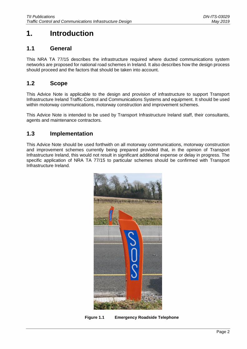
Figure 1.1 Emergency Roadside Telephone
TII Publications DN-ITS-03029 Traffic Control and Communications Infrastructure Design May 2019
Page 3
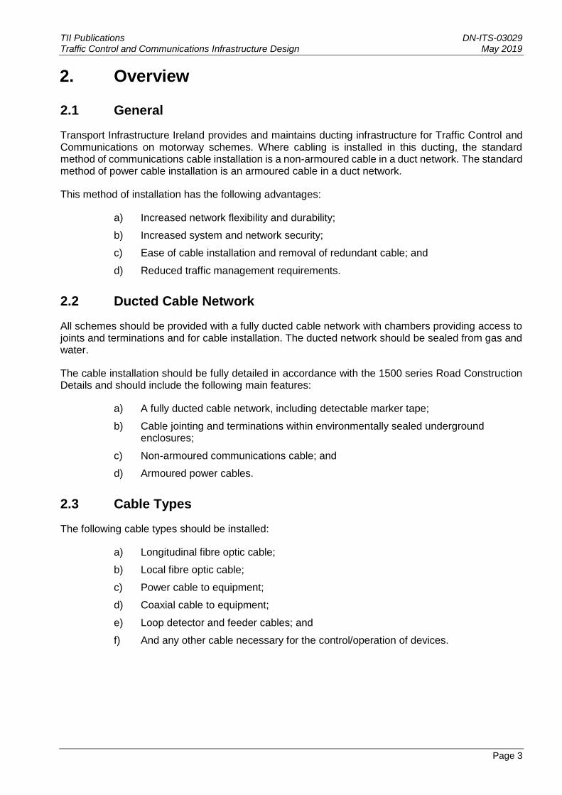
2. Overview
2.1 General
Transport Infrastructure Ireland provides and maintains ducting infrastructure for Traffic Control and Communications on motorway schemes. Where cabling is installed in this ducting, the standard method of communications cable installation is a non-armoured cable in a duct network. The standard method of power cable installation is an armoured cable in a duct network.
This method of installation has the following advantages:
a) Increased network flexibility and durability;
b) Increased system and network security;
c) Ease of cable installation and removal of redundant cable; and
d) Reduced traffic management requirements.
2.2 Ducted Cable Network
All schemes should be provided with a fully ducted cable network with chambers providing access to joints and terminations and for cable installation. The ducted network should be sealed from gas and water.
The cable installation should be fully detailed in accordance with the 1500 series Road Construction Details and should include the following main features:
a) A fully ducted cable network, including detectable marker tape;
b) Cable jointing and terminations within environmentally sealed underground enclosures;
c) Non-armoured communications cable; and
d) Armoured power cables.
2.3 Cable Types
The following cable types should be installed:
a) Longitudinal fibre optic cable;
b) Local fibre optic cable;
c) Power cable to equipment;
d) Coaxial cable to equipment;
e) Loop detector and feeder cables; and
f) And any other cable necessary for the control/operation of devices.

TII Publications DN-ITS-03029 Traffic Control and Communications Infrastructure Design May 2019
Page 4
3. Network Description
3.1 Introduction
The network should comprise the following, which are described in this chapter:
a) Cable network;
b) Duct network;
c) Roadside electronic equipment;
d) Power supplies.
The design of the network should take account of the existing cable network and the effect which the design will have upon it.
3.2 Communications Cable Network
Non armoured communications cable should be installed in underground ducts.
3.3 Power Supply Cable Network
Armoured power cabling should be installed in underground ducts.
3.4 Longitudinal Optical Fibre Cable Network
A longitudinal optical fibre cable should be provided to carry data between roadside equipment and the respective control office.
Fibre splices should be housed in Cable Joint Enclosures (CJE) installed inside underground chambers.
Roadside equipment should be connected to adjacent longitudinal fibre optic cable via network equipment housed in roadside equipment cabinets and local fibre optic cable installed in the duct network.
3.5 Duct Network
The duct network is described fully in Chapter 7. In summary it should comprise the following on the motorway network:
a) 100mm internal diameter 4-way longitudinal ducting, with local duct connections to equipment and transverse ducts;
b) Chambers at transverse duct locations (Type COMMS I), at 500m (tolerance +2%;-5%) intervals;
c) Intermediate chambers (Type COMMS II) at 250m offset from the chambers at transverse duct locations, and where necessary to facilitate cable installation (such as at a structure, a cabinet location or change in direction).
TII Publications DN-ITS-03029 Traffic Control and Communications Infrastructure Design May 2019
Page 5
3.6 Roadside Electronic Equipment
Roadside Electronic equipment should be housed in Roadside Equipment Cabinets. The Roadside Equipment Cabinets should be sealed and contain thermostatically controlled heaters and power distribution units.
This equipment may include Traffic Monitoring Units (TMU), Automatic Number Plate Recognition (ANPR), Closed Circuit Television (CCTV), Variable Message Signs (VMS), Automatic Traffic Counter (ATC), Automatic Incident Detection (AID), and communications equipment.
3.7 Power Supplies
Electricity Supply Company Interface (EI) equipment should be housed in electrical pillars and/or metering cabinets which are typically installed on the motorway boundary line.
Power to roadside equipment cabinets should be distributed from the EI pillars
Power should be distributed from the EI cabinets to the roadside equipment cabinets and then onto the equipment on the motorway. The power supply cable should be routed to the roadside equipment cabinets via a mini-pillar adjacent to the roadside equipment cabinet.
3.8 Protection of Existing Cable
When planning work on an existing road network, special consideration should be given to the protection of the existing traffic control and communications infrastructure. The longitudinal cable is part of the national network in addition to its function of carrying local data from roadside electronic equipment. Any damage to the cable will therefore cause disruption to roadside electronic equipment over an extremely wide area.
An existing communications report should be produced which will include an assessment of how the scheme will affect the existing communications network and the provisions necessary to maintain the integrity of the network. Where it is impossible to avoid interruption, the existing network should still be maintained operational to the maximum extent possible.
During the design stage the location of all cable and equipment should be determined, and an assessment made of the risk of damage. In general, where works are to be undertaken on a verge containing cable and equipment, there will be a significant risk of damage. It should be noted that the opposite verge is likely to also contain equipment and power supply cables which will therefore be vulnerable to damage from works on this verge.
3.9 Precautions to Avoid Damage to Existing Cable
The precautions required will depend on many factors including the risk of damage and the communications infrastructure to be provided by the national road scheme.
Where works are to be undertaken in close proximity to existing cables or duct, the exact location of the cables and duct should be positively identified (horizontal and vertical) and marked clearly prior to the commencement of any works. It may be possible to fence off the vulnerable area with temporary fencing, taking care not to damage cable or duct whilst installing fence posts.
Consideration should be given to programming the works to avoid working adjacent to live cables wherever possible.
TII Publications DN-ITS-03029 Traffic Control and Communications Infrastructure Design May 2019
Page 6
It will not be permissible to excavate by mechanical means in the vicinity of existing cables or ducts.
This should be taken into account during the planning stage and due allowance should be made for
excavation by hand as appropriate. This may affect the planned duration of site works.
3.10 Cable Damage and Replacement
All instances of damage to cable should be regarded as serious. All cable damage should be
reported immediately to the Employer’s Representative by the Contractor. Transport Infrastructure
Ireland should be informed as soon as practicable.
All damaged cables should be replaced at the contractor's cost. Where cable is to be replaced the
complete section, between joints, must be replaced. The replacement cable shall, as a minimum,
match the specification of the cable being replaced. Ideally replacement will be undertaken during
the contract period. If this is not possible then all reasonable costs incurred by Transport
Infrastructure Ireland in replacing the cable, including traffic management, will be recovered from the
contractor.
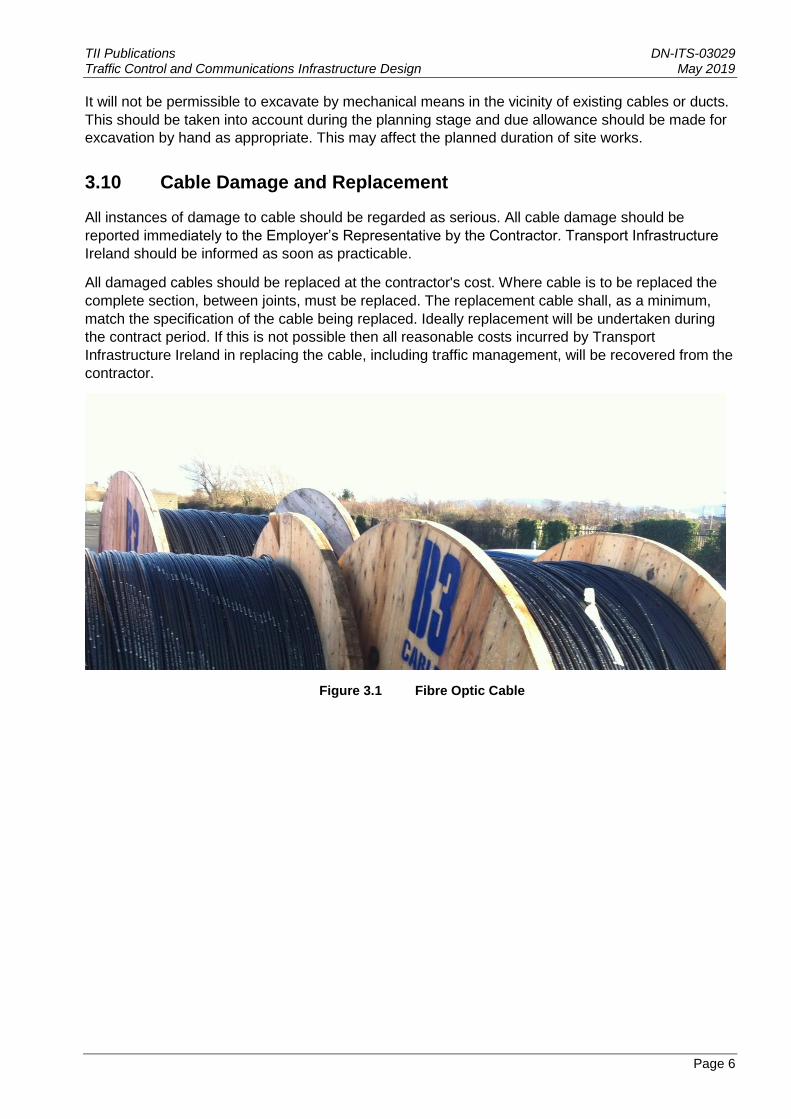
Figure 3.1 Fibre Optic Cable
TII Publications DN-ITS-03029 Traffic Control and Communications Infrastructure Design May 2019
Page 7
4. Motorway Cables
4.1 Armoured Power Cable
Armoured power cables should be used for the electrical network associated with the Traffic Control and Communications systems.
Typically, the low voltage armoured power cables should be stranded copper XLPE/SWA/PVC 600/1000V, with a PVC bedding and sheath. All cables should be external grade, suitable for use in the outdoor environment and cable sheaths should be flame retardant.
4.2 Armoured Copper Communications Cable
The cable should be external grade, rodent proof, Category 3, consisting of copper conductors, PVC insulated, polyester taped. The cable conductors should be colour coded to facilitate individual identification.
The cable should have a form of inbuilt protection appropriate to protect from the risk of damage from both mechanical and environmental hazards on the project.
The cable should be a fully filled copper communications cable sheathed with medium density polyethylene with a single layer of galvanised steel wire armour. The makeup of the cable should be in the form of a centre and a number of concentric layers. It should be constructed from solid plain 0.5mm2 copper conductors insulated with solid polyethylene and twisted together to form pairs.
4.3 Armoured Composite Optical Fibre/Copper Cable
The cable should be external grade, rodent proof, Single-Mode Fibre, category OS2.
This cable should be a fully filled single mode composite optical fibre cable, sized adequately to meet the specific project requirements. The cable should be sheathed in polyethylene and should be constructed from a number of cable elements formed around a central strength member producing a ‘loose tube’ arrangement so that any cable strain is not immediately imparted to the optical fibres. The cable should have a galvanised steel wire armour applied to the inner sheath and a polyethylene outer sheath.
The cable should consist of an outer jacket which is coloured as per industry standard for fibre type. The cable fibres should be colour coded to facilitate individual fibre identification. The cable fibre should be manufactured with an internal vapour deposition process such as the MCVD (Modified Chemical Vapour Deposition) or PCVD (Plasma Clad Vapour Deposition) processes.
The Fibre Optic cable should be installed in a duct network however the cable type should be suitable for direct burial or aerial lashed applications in the outside plant environment, providing full water blocking protection for external equipment applications.
TII Publications DN-ITS-03029 Traffic Control and Communications Infrastructure Design May 2019
Page 8
5. Network Design
5.1 General Procedure
This chapter deals with the design of ducted cable networks.
5.2 Design Process
The design process should be iterative. All items of roadside equipment and cable joints should have their ‘ideal’ locations; however, the most efficient design will be one which achieves the balance between ideal locations, physical constraints and cost. For instance, minor adjustments to locations may result in duct, cable or equipment savings.
The first stage in the design of a communications network is to correctly site all communications devices on 1:10000 scale drawings. This design should be transferred to the 1:2500 scale drawings, and a schematic design produced. The longitudinal cables should then be designed and added to the drawings. All local cables and items of equipment should then be added to the schematic design which is then transferred back to the 1:2500 scale drawings. The locations of equipment, chambers and cabinets should then be checked against physical constraints and adjusted accordingly to ensure that staff access can be maintained.
5.3 Duct and Chamber Design
Following the initial schematic communications design, ducts and chambers should be positioned.
Provisional sites should then be refined to site chambers in the optimum positions.
5.4 Selection of Duct Route
One of the earliest tasks in the design process is to determine the most suitable route for the longitudinal duct. The planning of this should involve plotting a suitable route on drawings at 1:2500 scale and a survey of the site to confirm the suitability of the chosen route.
All ducts should be laid within the road network boundary.
Where bases for equipment such as CCTV cameras or large signs coincide with the duct route these bases should be designed to allow ducts to be built in.
When planning the duct route the precise locations of all proposed and existing communications cables, duct routes and other relevant features should be plotted, from the schematic design, onto drawings at 1:2500 scale. Relevant features include:
a) Cuttings/Embankments;
b) Structures including bridges, retaining walls;
c) Drains;
d) Safety fences;
e) Lighting and other cables;
f) Gantries or verge mounted signs;
g) Noise fences;
TII Publications DN-ITS-03029 Traffic Control and Communications Infrastructure Design May 2019
Page 9
h) Overhead and underground services;
i) Environmental mounds; and
j) Trees.
The presence of particular features may require the use of special methods of construction or special items of plant or machinery. For example, installing ducts behind safety fencing on a steep embankment would be beyond the capabilities of standard mechanical excavators. This may, in turn, require special traffic management arrangements or result in the need for night working. All such details should be included in tender documentation.
The longitudinal cable should normally be kept on the same side of the motorway throughout its length, or at least, for a substantial distance. The side chosen will depend on the balance of advantages and disadvantages after considering such features as:
a) Cuttings/Embankments;
b) Flood plains;
c) Overhead power lines or electrified railway or buried power cables;
d) Relationship to Transmission Stations and cables/ducts on adjacent sections of motorway;
e) Ease of siting cabinets including access and safety protection;
f) Ease of providing power supplies;
g) Ease of routing duct.
5.12 Ducts to local equipment should occupy the same trench as longitudinal ducts as far as practicable. When choosing the route for a local duct the guidance given for longitudinal duct route selection will apply.
TII Publications DN-ITS-03029 Traffic Control and Communications Infrastructure Design May 2019
Page 10
6. Power Supply Design
6.1 Overview
230 volt (+10%, -10%) single phase AC mains power supplies are required for roadside electronic equipment.
Although roadside electronic equipment operates at 230V single phase many power distribution pillars are 3 phase.
6.2 Types of Installations
6.2.1 Motorway Supplies
Power supplies will normally be obtained from the Electricity Supplier (ES). On existing motorways, the existing supplies may need to be reviewed.
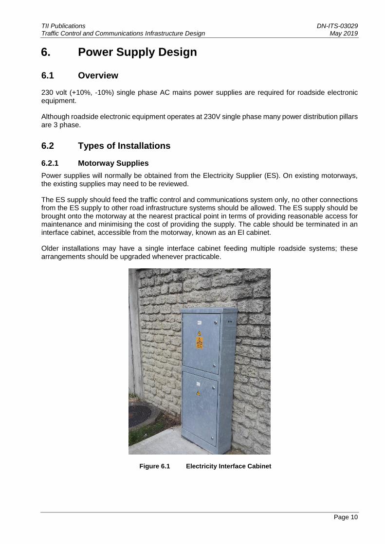
The ES supply should feed the traffic control and communications system only, no other connections from the ES supply to other road infrastructure systems should be allowed. The ES supply should be brought onto the motorway at the nearest practical point in terms of providing reasonable access for maintenance and minimising the cost of providing the supply. The cable should be terminated in an interface cabinet, accessible from the motorway, known as an EI cabinet.
Older installations may have a single interface cabinet feeding multiple roadside systems; these arrangements should be upgraded whenever practicable.
Figure 6.1 Electricity Interface Cabinet
TII Publications DN-ITS-03029 Traffic Control and Communications Infrastructure Design May 2019
Page 11
6.2.2 Local Supplies
Local supplies to equipment housed in Roadside Equipment Cabinets, a gantry or cantilever, will require a local power isolation mini-pillar.
6.2.3 Operational and Design Requirements
Electrical installations should conform, where applicable, to the following regulations:
i. ET101:2008 ‘National Rules for Electrical Installations, Fourth Edition’ and Updates (Amendments, Corrigenda and Errata) 06/2009 by the Electro-Technical Council of Ireland (ETCI).
ii. Current ESB and ESBN Regulations, Codes of Practice and Guidelines including ESB National Code of Practice for Customer Interface 4th Edition 2008.
iii. BS 7430 ‘Code of Practice for Earthing’.
6.2.4 Design
ET101:2008 should be adhered to for all of electrical installations.
6.2.5 Voltage Considerations
In accordance with ET101:2008, for installations rated not greater than 80A, the voltage drop should be restricted to a maximum of 4%.
6.2.6 Safety Considerations
The automatic disconnection of supply time should be provided in accordance with Chapter 4 of ET101:2008.
Where a gantry spans both carriageways an electrical cabinet should be provided in both verges and the switching arrangement should be such that the gantry can be isolated from either cabinet.
Power isolation locations are required on the electrical network to ‘switch off’ power. Whilst maintenance or alterations are carried out, these power isolation locations should be lockable in the ‘off’ position.
6.3 Design - Particular Requirements for Motorway Installations
6.3.1 Power Distribution
Power distribution networks to roadside equipment cabinets should be star networks centred on EIs.
Electrical and electronic systems associated with the Traffic Control and Communications installation should be protected from damage which may be caused by lightning electromagnetic impulse by the provision of surge protection. The designer should carry out a risk analysis to determine whether surge protection is required and if so, for which Motorway Communication systems.
6.3.2 Design – Equipment Loads
Typical electrical loads associated with Motorway Communication equipment are as indicted in Table 6.1, however it is the designers’ responsibility to verify all electrical loads with the equipment manufacturer prior to commencement of the electrical network design.
TII Publications DN-ITS-03029 Traffic Control and Communications Infrastructure Design May 2019
Page 12
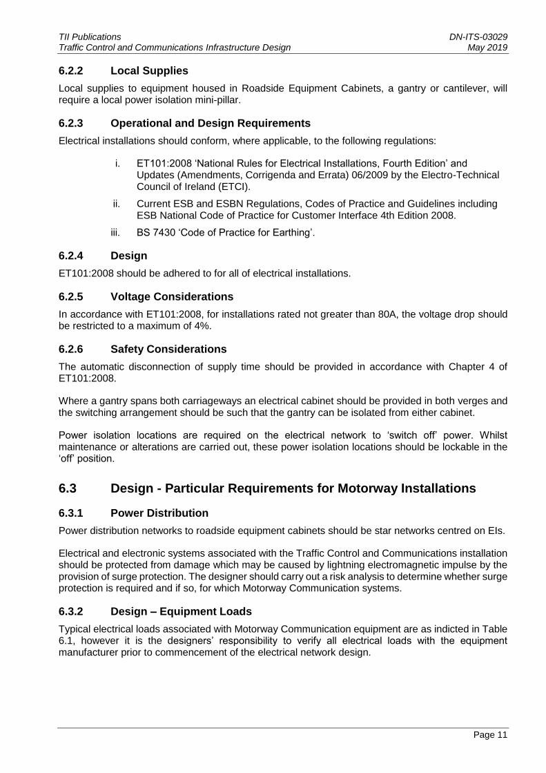
Table 6 1 Nominal Electrical Load of Motorway Communications Equipment
Nominal Electrical Load of Motorway Communications Equipment
Equipment Power (W)
Variable Message Sign - MS4 2,000
Variable Message Sign - MS3 5,000
Roadside Equipment Cabinet 2,000
Full Portal Gantry 10,000
Entry Signals (per site) 4,000
6.3.3 Design – Power Cables
Armoured cable should be used for power distribution associated with Traffic Control and Communications systems. The conductors should typically be stranded copper and have a PVC bedding and sheath unless otherwise agreed.
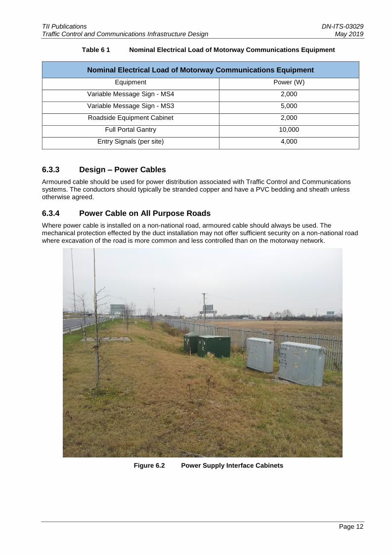
6.3.4 Power Cable on All Purpose Roads
Where power cable is installed on a non-national road, armoured cable should always be used. The mechanical protection effected by the duct installation may not offer sufficient security on a non-national road where excavation of the road is more common and less controlled than on the motorway network.
Figure 6.2 Power Supply Interface Cabinets
TII Publications DN-ITS-03029 Traffic Control and Communications Infrastructure Design May 2019
Page 13
7. Cable Ducts
7.1 General
The standard method of cable installation should be a non-armoured cable installed in duct.
The ducted network should consist of 100mm internal diameter longitudinal ducts located in the verge or earthworks, offset at a nominal 2m from the back of hard shoulder, and transverse ducts at 500m centres crossing beneath the carriageway at right angles to it.
The ducted network should be sealed.
Cables for street lighting must not be laid in the same duct as cables for motorway communications.
7.2 Material and Installation Standards
The material specification for ducts shall be provided in accordance with the 1500 Series of the Specification. Ducts should be manufactured from thermoplastic material.
Each length of ducting should be fitted with a non-rotting stranded draw rope and the duct ends fitted with purpose made compression plugs providing a water, air and gas tight seal, as detailed in the 1500 Series of the Specifications.
Joints between adjacent lengths of ducts should be air and water tight. It is imperative that material such as silt, grout or concrete is prevented from entering the duct during the jointing process. Material such as this will cause damage to the cable during installation.
7.3 Longitudinal Ducts
Design standards should be as detailed on the Series 1500 Motorway Road Construction Detail (RCD) drawings, contained in Volume 4 of the NRA Manual of Contract Documents for Road Works (MCDRW).
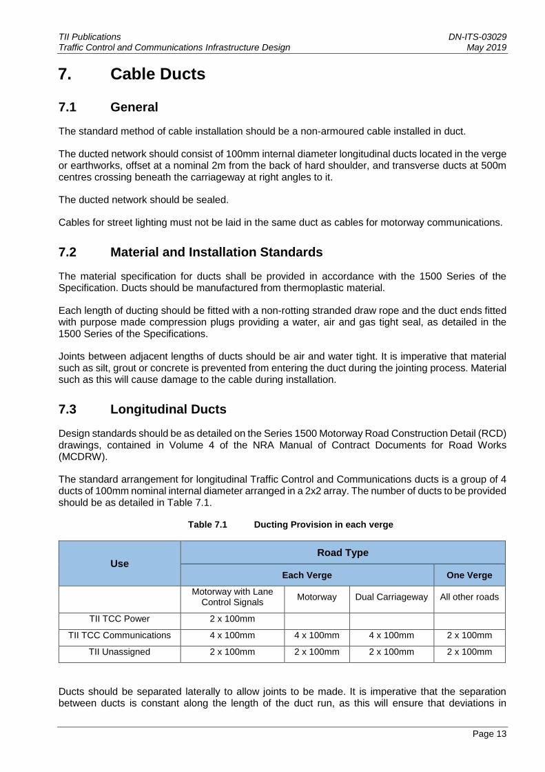
The standard arrangement for longitudinal Traffic Control and Communications ducts is a group of 4 ducts of 100mm nominal internal diameter arranged in a 2x2 array. The number of ducts to be provided should be as detailed in Table 7.1.
Table 7.1 Ducting Provision in each verge
Use Road Type
Each Verge One Verge
Motorway with Lane
Control Signals Motorway Dual Carriageway All other roads
TII TCC Power 2 x 100mm
TII TCC Communications 4 x 100mm 4 x 100mm 4 x 100mm 2 x 100mm
TII Unassigned 2 x 100mm 2 x 100mm 2 x 100mm 2 x 100mm
Ducts should be separated laterally to allow joints to be made. It is imperative that the separation between ducts is constant along the length of the duct run, as this will ensure that deviations in
TII Publications DN-ITS-03029 Traffic Control and Communications Infrastructure Design May 2019
Page 14
alignment are kept to the absolute minimum. To ensure that ducts remain in position during installation, in particular during backfilling operations, they should be strapped or clipped together at intervals of no more than 2m. A purpose made spacer, inserted at the strapping/clipping positions will ensure that the required spacing is maintained. Alternatively, a purpose made spacer/clip can serve the dual purpose of spacing and retaining ducts.
Ideally ducts should be laid in straight lines from one chamber to the next. In practice this will rarely be achievable due to the alignment of the motorway. Ducts should be installed to a smooth alignment which follows the road layout. Any changes in horizontal or vertical alignment will form pinch points where cables will incur damage during installation.
Longitudinal ducts should be located to the rear of all other services and equipment including safety fence, drainage and lighting columns. The nominal offset from the back of the hardshoulder should be 2m. Ducts should be installed in a trench with 600 mm of cover. Trench details for ducts are shown on the 1500 series RCD drawings.
The optimum location for cable ducts is within a flat verge. This will automatically be achieved in areas where verge widening occurs or where additional land adjacent to the carriageway is required for other purposes, such as landscaping.
In some circumstances, it will be necessary to deviate from the nominal offset. For example, where there is limited width available or non-existent conventional verges, such as in areas of retained cutting. In these cases, the duct may be located under the hardened verge. Cable draw pits can be located either in the centre of the wheel-track zone in the hard shoulder or within the hardened verge.
Special consideration should be given to the installation of ducts at structures. If possible, ducts should be buried in the hardened verge, but the presence of other services, or the design of the structure, may prohibit this and alternative arrangements should be made. It is important that 4 x 100mm ducts are provided. In the instances where it is not possible to provide 4 x 100mm ducts these locations should be marked clearly on the drawings to allow the cable designer to adjust the design accordingly. Approval to proceed will be required from Transport Infrastructure Ireland where 4 x 100mm ducts are not proposed.
7.4 Geotechnical Considerations
In many cases ducts will be located in the verges adjacent to earthworks slopes. Excavation of trenches in, or next to, these slopes can lead to problems with slope stability. The geotechnical implications of this should be checked for each scheme.
Additional information on ground conditions and slope parameters may be required to inform the design process.
The excavation of a trench at the toe of a cutting should be dealt with carefully as poor design and poor workmanship could lead to a local failure of the slope. Problems can be avoided by the use of a narrow trench (typically 0.5 m) and by ensuring that, during construction, trenches are excavated in relatively short lengths and not left open for extended periods. Proper specification of trench fill material combined with high standards of compaction will also minimise the risk of failure. Where a slope is identified as being at risk special precautions will be required in both design and construction.
The excavation of a trench at the crown of an embankment slope should be approached with care. The problem in this instance would be that the trench could act as a drain, collecting surface run-off without having an outfall. The build-up of water would, in cohesive soils, eventually saturate and weaken the surrounding soil.
TII Publications DN-ITS-03029 Traffic Control and Communications Infrastructure Design May 2019
Page 15
This problem can quite readily be avoided by the use of a properly specified and constructed trench detail and where necessary, by the use of special details such as a geotextile seal near the surface of the trench.
The location of longitudinal ducts within a flat verge, cutting and embankment is shown on the series 1500 RCD drawings.
7.5 Transverse Ducts
Transverse ducts should provide the means by which cables may cross carriageways from one verge to the other and from one side of a slip road to the other.
The minimum requirement is a group of four 100 mm diameter ducts at nominal 500m intervals as detailed on the 1500 series RCD Drawings.
The 1500 series RCD drawings show a typical arrangement of carriageway crossings at slip roads and link roads.
The depth of transverse ducts is dictated by the following factors:
a) The pavement construction depth;
b) The method of duct installation to be used;
c) The need to ensure that adequate protection to the duct is achieved, both during construction and under long term vehicular loading;
d) The location of drains; and,
e) Whether the road is new or existing.
7.6 New Roads
For new roads, transverse ducts should be laid in a trench excavated in the material below the capping layer. Ducts should not be located within the capping layer as this could result in the formation of hard spots which could affect the surface of the carriageway above. The minimum cover to transverse ducts should be either:
a) 900 mm if the ducts are covered by a 150 mm thick concrete slab, or
b) 1200 mm if no concrete cover is provided
In all cases the ducts should be located at least 150 mm below the bottom of the capping layer, or if no capping layer is required, at least 150 mm below the formation level.
7.7 Existing Roads
Where possible transverse ducts should be installed beneath existing carriageways, using trenchless techniques. The depths of these ducts will be dependent upon the material in which the ducts are to be located, the likely impact of the installation method on the surrounding ground and the location of drainage pipes. The minimum depths detailed above for ducts in trenches apply also to trenchless ducts, but these depths may have to be increased to ensure that the displacement of the surrounding ground does not affect the structural integrity of the pavement construction or capping layer.
TII Publications DN-ITS-03029 Traffic Control and Communications Infrastructure Design May 2019
Page 16
It is imperative that as-built records of pavement construction drainage and other services and geotechnical records are consulted when planning trenchless crossings of motorways.
A number of reliable well proven methods of trenchless ducting provision are currently available including:
a) Auger boring;
b) Guided, steerable moles;
c) Thrust boring;
d) Impact moling;
e) Pipe ramming.
Careful consideration of factors such as ground conditions and local topography will be required before choosing a method of installation. The choice of an unsuitable method can have costly implications. It should be noted that when installing ducts in this manner, it is advisable not to install ducts in close proximity to each other to avoid ducts clashing.
7.8 Special Arrangements at Structures
On long structures, special arrangements may be necessary if transverse ducting at 500 m intervals cannot be provided. Early advice should be sought from Transport Infrastructure Ireland.
Special details will be required where ducts cross expansion joints.
Where separate viaducts are constructed for each carriageway, provision for cabling between the structures may be required.
7.9 Local Ducts
Local ducts should be used to connect equipment to the longitudinal and transverse duct network. One of the four ducts in the longitudinal network should be allocated for local cabling.
Where additional local ducts are required for cabinets and devices, they should be 100mm internal diameter and run from the nearest chamber either directly to the equipment or, via type intermediate chambers, to the cabinet site. Separate ducts for communications and power cables should also be provided. Local ducts forming connections to emergency roadside telephones should be 50 mm diameter.
Local ducts should be laid in the same trench as longitudinal ducts. The RCD drawings show the standard trench detail for local ducts.
Where the distance between the cabinet site and the nearest chamber on the longitudinal duct network is more than 120m, an additional chamber should be installed, on the line of the main duct run, at the cabinet site as shown in the 1500 series RCD drawings. The ducts allocated to longitudinal cables and spare ducts should be continuous through the chamber at this location.
7.10 Use of Existing Ducts
Existing ducts are likely to be limited to transverse ducts and ducts at structures.
TII Publications DN-ITS-03029 Traffic Control and Communications Infrastructure Design May 2019
Page 17
7.11 Transverse Ducts
Transverse ducts are often extremely difficult to locate on existing motorways. The most common reason for this being that duct marker posts and blocks were not provided and where they have been provided they have rarely been maintained. Inaccurate as-installed information on ducting is common. The Authorities should keep records of duct location and usage up to date.
As the cost of providing new transverse ducts is relatively high, the utilisation of existing ducts should be considered. This will only be acceptable where the existing ducts meet the material and installation standards, and where they occur at locations which suit the proposed cable network.
A locational survey of existing ducts should be undertaken during the design stage to establish where existing ducts can be used, where new ducts are required and where cable routes may be revised to avoid the need for new ducts.
The survey should include accurate details of duct location (chainage and offset) and type, soundness of duct, its depth, diameter and the number and type of cables installed.
Empty ducts should be proved and cleared of debris using a mandrel.
Ducts containing existing cables should be used with extreme caution as cables will probably be snaked and twisted, the duct may be damaged internally, and debris may have accumulated within the duct. Wherever possible, redundant cables should be identified and removed.
7.12 Ducts at Structures
It will frequently be found that where longitudinal ducts have been installed at structures, they have been provided only for existing cables with no additional capacity. This additional capacity can generally be provided by one of the following methods:
a) At a bridge which has a safety barrier and separate fence or parapet, it is often possible to lay ducts between them;
b) At a bridge which has no separate safety fence it may be practicable to attach ducts to the outside of a parapet;
c) It may be possible to install ducts in the hardened verge;
d) It may be possible to install ducts beneath the bridge surface, using the structure itself. For example, within a concrete box section or attached to steel girder sections.
The agreement of Transport Infrastructure Ireland Structures Section is required before proceeding with any of the above options.
7.13 Equipment Siting on Existing Motorways
When siting telephones, signals and other equipment on existing motorways, their locations should be planned such that the number of new duct crossings is minimised.
7.14 Ducts at Junctions
Ducts should be provided at junctions as shown on the 1500 series RCD drawings. It is important that all ducts start and finish on land belonging to Transport Infrastructure Ireland.

TII Publications DN-ITS-03029 Traffic Control and Communications Infrastructure Design May 2019
Page 18
7.15 Marker Tape
Ducts should be installed in a trench as detailed in the 1500 series RCD drawings. The trench detail includes the installation of a detectable marker tape which will allow the ducts to be located using electronic cable detecting equipment. It is important that adjacent lengths of marker tape are jointed correctly to achieve electrical continuity.
7.16 Duct Allocation
Cables should be installed into nominated ducts as detailed in the 1500 series RCD drawings.
TII Publications DN-ITS-03029 Traffic Control and Communications Infrastructure Design May 2019
Page 19
8. Chambers
8.1 Chamber Types
Three types of chambers are utilised within the ducted network as described below. Details of the following chamber types are contained within the RCD drawings.
Type COMMS I - these are Main/Joint chambers. They are required to accommodate cable joints and at the junction of transverse and longitudinal ducts. They should be 1.3m x 0.75m in plan and sufficiently large to accommodate transverse, longitudinal and local ducts as well as joints and coiled cable. The Minimum depth of a jointing chamber should be 1.2m.
Type COMMS II - these are intermediate chambers which should be located on longitudinal duct runs where changes in direction are encountered. They may be required where cabinet sites are located at a distance of more than 120m from the nearest Type COMMS I chamber. The maximum depth of a Type COMMS II chamber should be 1.0m, where a deeper chamber is required a Type COMMS I chamber should be used
Type COMMS III - these are shallow chambers and are required in front of cabinets to ensure that the duct network remains enclosed.
Additional chambers are required at other locations such as slip road crossings, changes in alignment where additional chambers will facilitate cable installation, and at structures. It should be noted that at locations where cable joints are to be installed, Type COMMS I chambers may be required for access and cable management requirements.
8.2 Chamber Siting
Type COMMS I chambers should be located typically at 500m (+2%, -5%) intervals along the length of the longitudinal ducts. Preferably they should coincide with the position of transverse ducts.
Type COMMS II chambers should be provided, as required, on the longitudinal duct run. Type COMMS II chambers should only be required where equipment sites are further than 120m from the nearest Type COMMS I chamber and at changes in direction.
Type COMMS III chambers should be provided at cabinet sites as detailed in the 1500 series RCD drawings.
Type COMMS I and II chambers will generally be located at an offset of 2.0 m from the hard shoulder. It is likely that retaining walls may therefore be required at chamber locations. They should be designed to suit scheme specific topographical/geotechnical conditions. Consideration should be given, where appropriate, to adjusting the level of the top of the chamber in order to overcome the need for a retaining wall.
Where there is a limited width available or a non-existent verge, such as in areas of retained cutting, chambers can be located either under the hardshoulder or within the hardened verge. It should be noted that wherever possible, chambers should be located away from obstructions or retained cuttings.
TII Publications DN-ITS-03029 Traffic Control and Communications Infrastructure Design May 2019
Page 20
8.3 Chambers at Structures
Where ducts are installed in structures, it is likely that they will be located at a different depth and offset to the main longitudinal duct run. This is due to the physical constraints of the structure.
At all such locations a chamber should be provided to allow cables to be installed. Generally, a Type COMMS II chamber should be provided; however, where the depth of the chamber exceeds 1m a Type COMMS I chamber will be required.
The difference in offset may require the provision of two chambers at each end of a bridge.
The location of safety fencing may affect the siting and construction of the chamber.
8.4 Drainage
During the design of the duct network the drainage of water from chambers should be considered. A suitable method should be provided to allow the free drainage of water from chambers in accordance with Series 500 of the MCDRW.
Chambers Type COMMS I and II are provided with a sump to allow the pumping out of water.
8.5 Labelling
Chambers should be labelled in accordance with the requirements of the 1500 Series Specification.
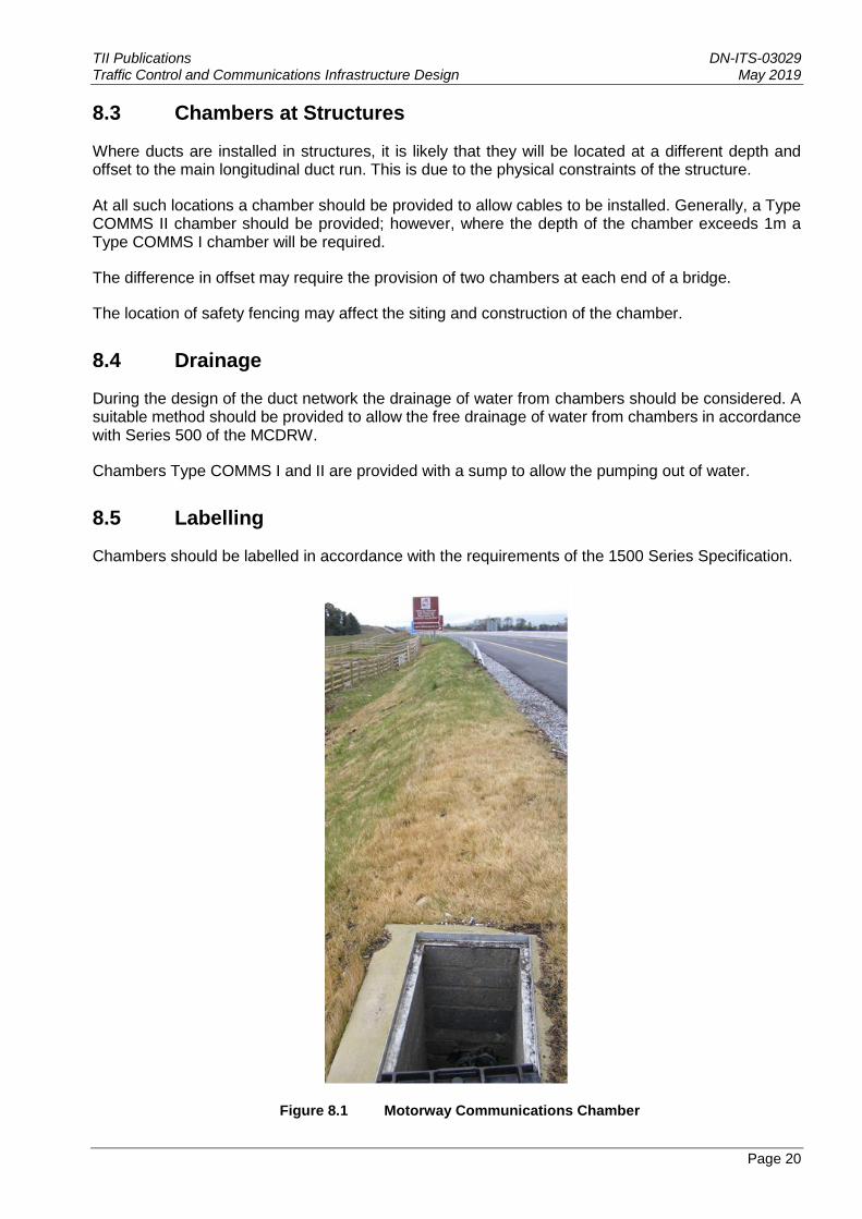
Figure 8.1 Motorway Communications Chamber
TII Publications DN-ITS-03029 Traffic Control and Communications Infrastructure Design May 2019
Page 21
9. Armoured Cable Installations
9.1 Direct Burial
Direct burial is no longer standard practice for the installation of motorway communication cables. All cables should be installed in an underground duct network as described in Section 7.
However, there may be exceptional cases where this method is appropriate, such as in the replacement of short lengths of existing direct buried cable or a local improvement scheme. The agreement of Transport Infrastructure Ireland is required before proceeding with this option.
9.2 Cable Types
Armoured cables are to be used for all power supply installations associated with the Motorway Communication systems.
Armoured cable requires testing by the installation contractor to confirm the integrity of the cable sheath in accordance with the most recent version of ET101, the ‘National Rules for Electrical Installations by the Electro-Technical Council of Ireland (ETCI).
9.3 Armoured Cable Terminations
Fibre optic cabling is to be terminated in accordance with the manufacturers requirements.
Armoured power cable cores are to be terminated with compression lugs or bootlace ferrules, as appropriate.
All power cables should have their conductors tested for insulation resistance immediately prior to terminating the cable end.
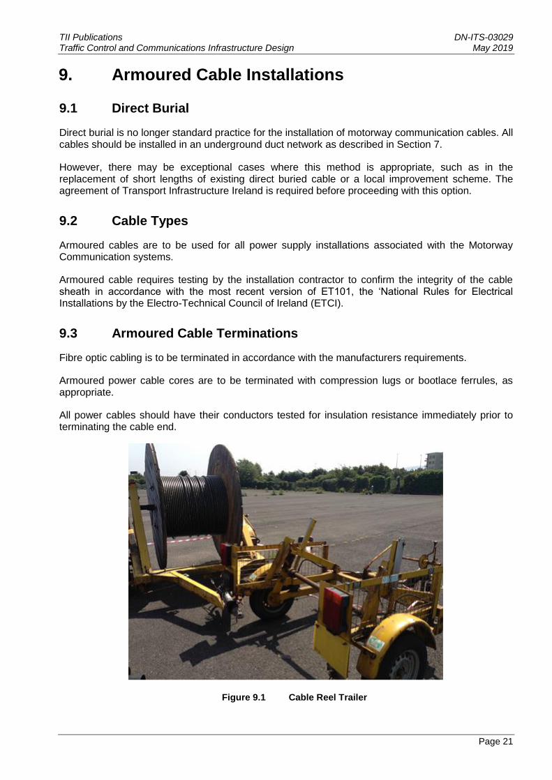
Figure 9.1 Cable Reel Trailer
TII Publications DN-ITS-03029 Traffic Control and Communications Infrastructure Design May 2019
Page 22
10. Cabinet Siting
10.1 Positioning
Suitable sites for cabinets should be assessed at the outset of the design. This assessment should aim to identify sites which are safe for maintenance personnel and do not present hazards to motorist that would require mitigation in the form of safety barrier. The assessment should also have due regard for cost and aesthetics. On a ducted network, cabinets should be located at the main/joint chamber sites to minimise the number of intermediate chambers required and the length of local ducts.
Since cabinets are weatherproof, but not waterproof, they should be sited well above any likely flood level.
Consideration needs to be given to reducing the number of cabinets by grouping together devices at the one location wherever possible as this has maintenance and capital cost savings advantages.
Where the motorway is sited in a cutting or on an embankment, care should be taken to ensure that cabinets do not cause visual intrusion for local residents or users of adjacent land.
Care should be taken to ensure that proposed or existing landscape planting is located so as not to cause access problems, for maintenance of either cabinets or the landscape planting itself, or obscure cabinets in future years.
10.2 Safety Barrier
Safety barrier may be required as mitigation in the event that communication equipment cannot be located outside the clear zone of the road. NRA TD 19 sets out the requirements for safety barriers to protect motorists from hazards within the clear zone of the road.
It may be possible to site cabinets downstream of bridge piers or behind safety barrier that already exists or is planned as mitigation for other hazards. It may be possible to site a cabinet where it can be protected by an extension to existing or planned safety barrier, which would be more acceptable on both economic and safety grounds. In such cases, the communications equipment must always remain outside of the working width of the safety barrier.
Short gaps between adjacent lengths of safety barrier should be avoided. Where necessary, additional safety barrier should be provided to close such gaps.
10.3 Retaining Walls
Special consideration should be given to the siting of cabinets in retained cuttings. Where cabinets are to be located at the top of such retaining walls, access from the hardshoulder should be provided. Where cabinets are located in cut-outs in retaining walls there may be difficulties in routing cables to cabinets.
Retaining walls required to retain cuttings for cabinets should be designed and detailed as part of the communications infrastructure.
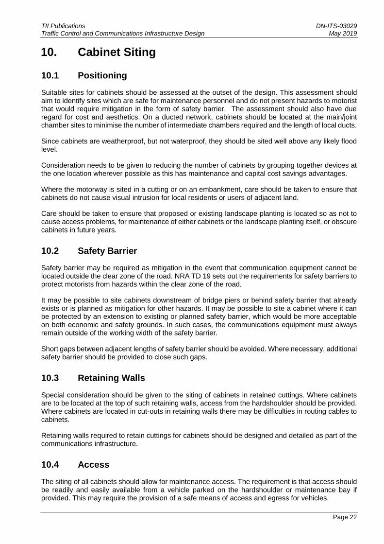
10.4 Access
The siting of all cabinets should allow for maintenance access. The requirement is that access should be readily and easily available from a vehicle parked on the hardshoulder or maintenance bay if provided. This may require the provision of a safe means of access and egress for vehicles.
TII Publications DN-ITS-03029 Traffic Control and Communications Infrastructure Design May 2019
Page 23
Cabinets which are sited remotely from the carriageway may require the provision of access steps as detailed within the RCD drawings.
Maintenance staff may be required to carry heavy test equipment to equipment sites. Therefore, steps should be provided where access involves a gradient exceeding 1 in 2 for a height exceeding 400mm.
Paved areas, constructed from standard paving slabs, should be constructed between access steps, cabinet hardstandings, the hardshoulder and any maintenance parking bays to provide a continuous, safe path.
Figure 10.1 Chamber on plinth
TII Publications DN-ITS-03029 Traffic Control and Communications Infrastructure Design May 2019
Page 24
11. Construction Detail
11.1 Equipment Cabinet Plinth
The standard of provision for plinths at cabinet and sites with equipment is given within the RCD drawings. Generally, a plinth should be provided at every cabinet door. Where two or more cabinets occur at one site, they should be linked by a paved area.
Where cabinets are situated on cutting or embankment slopes, consideration should be given to the provision of handrailing to protect maintenance personnel from the risk of falling.
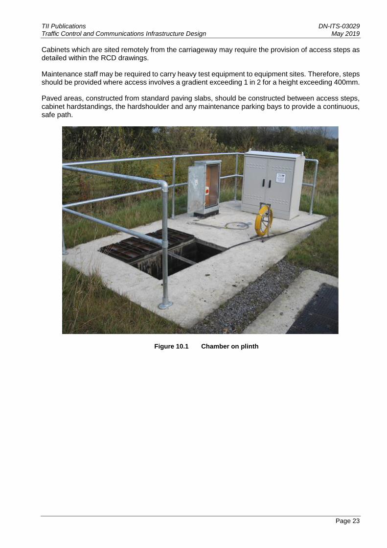
11.2 Steps
Typical access steps for cabinets should be as detailed on the 1500 series RCD drawings.
Where steps are specified, due consideration should be given to the Health and Safety implications of the specified layout. Consideration should also be given to the provision of handrailing alongside steps and also landings with guardrails to limit the height of individual flights of steps. Steps should not protrude from the cutting in such a way to cause a hazard to the motorists.
Where steps are provided, they should be linked to cabinet sites by a path constructed from standard paving slabs.
Figure 11.1 Access steps to plinth

TII Publications DN-ITS-03029 Traffic Control and Communications Infrastructure Design May 2019
Page 25
12. Weigh-In-Motion
All WIM systems shall meet the requirements in DN-ITS-03085.
All works shall be undertaken in accordance with Series 1500 of the Specification.
TII Publications DN-ITS-03029 Traffic Control and Communications Infrastructure Design May 2019
Page 26
13. Miscellaneous Equipment
13.1 Uninterruptible Power Supplies (UPS)
Where a UPS is required to provide continuous power supply to a Traffic Control and
Communications system in the event of a mains power failure, the UPS should be located in the
Roadside Equipment Cabinet and should be suitably rated for use in an outdoor environment.
Where located in a Roadside Equipment Cabinet, the UPS should typically be rack mountable. All
components should be contained in a single enclosure and it should provide continuous, transient
free power to critical loads regardless of voltage and frequency deviations and outages of the
normal mains supply.
The UPS should provide an autonomous power supply for a length of time which should be agreed
with Transport Infrastructure Ireland on a project specific basis but typically should be no longer than
30mins.
The UPS should be equipped with a network connection to allow for remote monitoring of the UPS
operational status.
13.2 Batteries associated with Motorway Communication Systems
Where Traffic Control and Communications systems require the use of batteries, they should
typically be installed within Roadside Equipment Cabinets and should be either shelf mounted or
housed within a dedicated enclosure.
Batteries should capable of maintaining the full specified current output for the required discharge
autonomy period at the rated output voltage.
Each battery should consist of a group of cells connected in series or in series-parallel to provide the
output voltage and the storage capacity as specified for the individual project.
For the purposes of safety, considerations should be given to providing instruction cards with each
battery installation, detailing operation and maintenance instructions along with highlighting any
safety precautions required.
Consideration should be given to the housing of the batteries in terms of battery performance and
maintenance. Typically, the batteries should be installed in cabinets with ventilation louvres to
minimise the concentration of gases and limit the temperature rise in accordance with the
manufacturer's recommendations. Access to the cells should also be available for maintenance and
testing when in the finally installed position.
Consideration should be given to the size and weight of the batteries to allow for ease of installation
into Roadside Equipment Cabinets and ease of on-going maintenance.
Automotive batteries designed specifically for vehicle starting duty should not be acceptable for use.
TII Publications DN-ITS-03029 Traffic Control and Communications Infrastructure Design May 2019
Page 27
14. Renewable Power Supplies
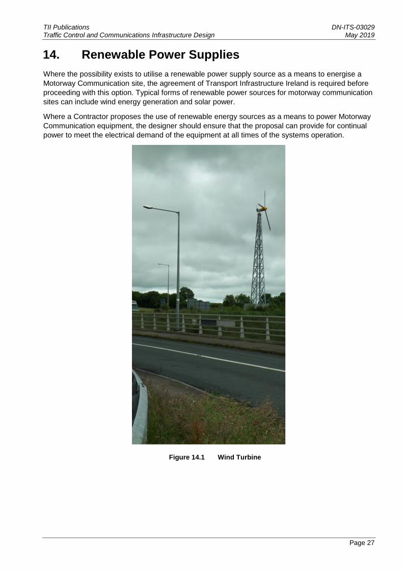
Where the possibility exists to utilise a renewable power supply source as a means to energise a
Motorway Communication site, the agreement of Transport Infrastructure Ireland is required before
proceeding with this option. Typical forms of renewable power sources for motorway communication
sites can include wind energy generation and solar power.
Where a Contractor proposes the use of renewable energy sources as a means to power Motorway
Communication equipment, the designer should ensure that the proposal can provide for continual
power to meet the electrical demand of the equipment at all times of the systems operation.
Figure 14.1 Wind Turbine
TII Publications DN-ITS-03029 Traffic Control and Communications Infrastructure Design May 2019
Page 28
15. Labelling
15.1 General
Accurate and legible informatory labels on the outside of cabinets, on cables and chambers are essential for the efficient working and safety of maintenance personnel.
It should be noted that the Engineer is responsible for specifying names, numbers and lettering on informatory and address coding labels.
15.2 Chambers
Covers for chambers should be provided with a label containing the legend “MOTORWAY COMMUNICATIONS” and a label indicating the motorway address.
15.3 Cabinets
Informatory, address coding and warning labels should be provided on cabinets.
All electrical equipment housed within electrical cabinets and pillars should be adequately labelled to allow safe and efficient working by maintenance personnel.
Each section of electrical cabinets/pillars should be clearly labelled showing the designation of the equipment being fed.
15.4 Warning Labels
It should be noted that an Electrical Safety Label in accordance with the National Rules for Electrical Installations by the Electro-Technical Council of Ireland (ETCI) and ESB’s National Code of Practice for Customer Interfaces should be fitted (and maintained) to electrical cabinets and pillars.
15.5 Cables
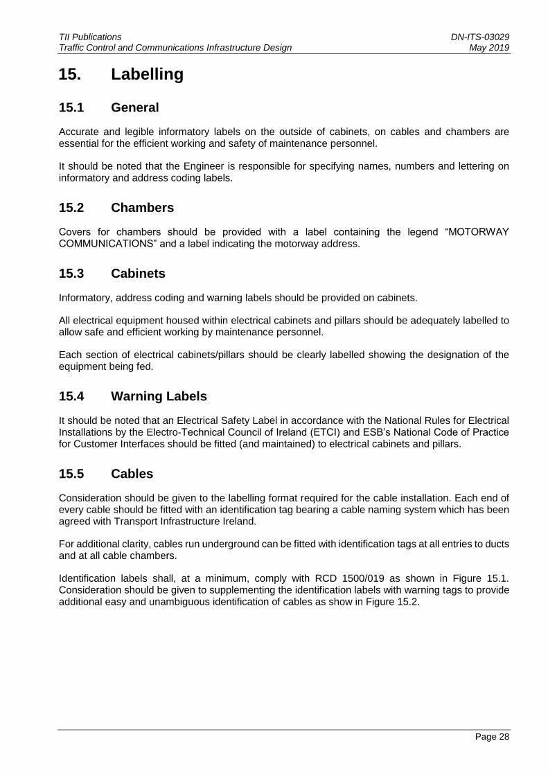
Consideration should be given to the labelling format required for the cable installation. Each end of every cable should be fitted with an identification tag bearing a cable naming system which has been agreed with Transport Infrastructure Ireland.
For additional clarity, cables run underground can be fitted with identification tags at all entries to ducts and at all cable chambers.
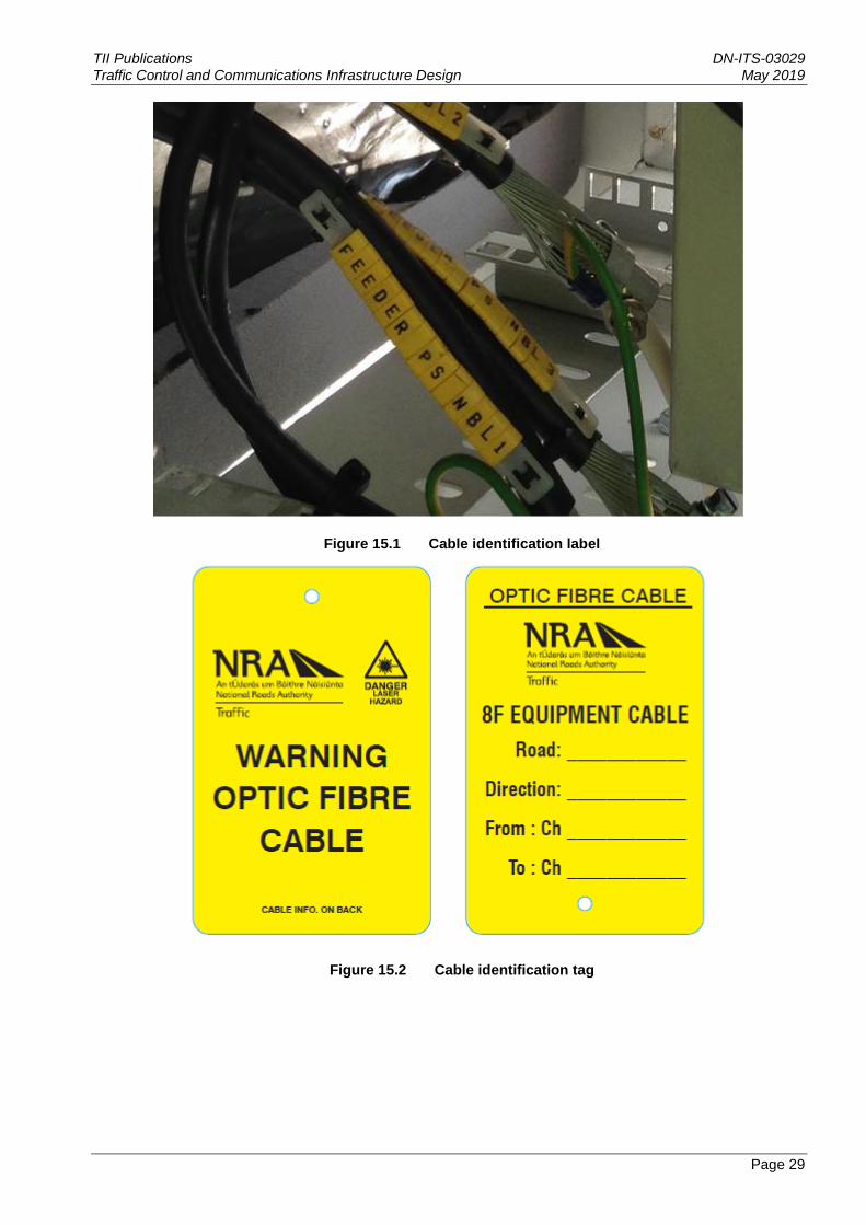
Identification labels shall, at a minimum, comply with RCD 1500/019 as shown in Figure 15.1. Consideration should be given to supplementing the identification labels with warning tags to provide additional easy and unambiguous identification of cables as show in Figure 15.2.
TII Publications DN-ITS-03029 Traffic Control and Communications Infrastructure Design May 2019
Page 29
Figure 15.1 Cable identification label
Figure 15.2 Cable identification tag

TII Publications DN-ITS-03029 Traffic Control and Communications Infrastructure Design May 2019
Page 30
16. References
16.1 National Roads Authority Publications:
NRA Design Manual for Roads and Bridges (NRA DMRB), generally and specifically:
NRA Manual of Contract Documents for Road Works (NRA MCDRW)
16.2 Transport Research
COST 323 Weigh-in-Motion of Road Vehicles

TII Publications DN-ITS-03029 Traffic Control and Communications Infrastructure Design May 2019
Page 31
17. Enquiries
All technical enquiries or comments on this document or any of the documents listed as forming part of the NRA DMRB should be sent by e-mail to [email protected], addressed to the following:
Director of Professional Services Transport Infrastructure Ireland Parkgate Business Centre Parkgate Street Dublin 8
……………………………………………
Helen Hughes
Director of Professional Service

TII Publications DN-ITS-03029 Traffic Control and Communications Infrastructure Design May 2019