traffic classification - bme-hitjakab/edu/litr/qos/traffic_classification_cisco__chap05.pdftraffic...
TRANSCRIPT

C H A P T E R
5-1WAN and Application Optimization Solution Guide
5Traffic Classification
In a typical network, the traffic through the network is heterogeneous and consists of flows from multiple applications and utilities. Many of these applications are unique and have their own requirements with respect to network parameters such as delay, jitter, etc. Unless these requirements are met, the quality and usability of these applications will be severely compromised. While meeting these requirements in a Local Area Network (LAN) with its huge bandwidth might be easy, it usually is a challenge to meet them on the WANs, which have bandwidth constraints.
Thus, traffic management on the WANs must exist in order to properly prioritize different applications across the limited WAN bandwidth and ensure that these requirements are met. In addition, a proper understanding of the applications and protocols in the network traffic is essential for any network manager to implement appropriate security policies. In a real network, user perception also matters. Although a user application might allow large delays or jitter, the user might be very sensitive to long wait times. Managing network traffic thus requires a judicious balance of all these priorities.
Classification of traffic is only the first step that helps identify different applications and protocols that exist in a network. Various actions, such as monitoring, discovery, control, and optimization can then be performed on the identified traffic with the end goal of improving the network performance. Typically, once the packets are classified (identified) as belonging to a particular application or protocol, they are marked or flagged. These markings or flags help the router determine appropriate service policies to be applied for those flows.
In other words:
• Classification is a technique that identifies the application or protocol, and
• Marking is the process that colors the packets (or just lets them through untouched) based on certain classification policies, which are used by the routers internally, or further downstream (depending on the kind of coloring) to provide appropriate treatment to those packets.
There are two other approaches to classifying traffic:
• Classifying the packet based on the payload, that is, Payload-Based Classification. In this method, packets are classified based on the fields of the payload, such as Layer 4 ports (source or destination or both)
• Classification based on a statistical method that uses statistical analysis of the traffic behavior like inter-packet arrival, session time, and so on
The payload-based method is most prevalent. However, more often than not, it fails with encrypted and tunneled traffic. The Payload-Based Classification technique can be divided into generic or basic payload analysis or advanced payload analysis. The generic approach to traffic classification is based on information in the IP header. Typically, the following information is looked at.
• Layer 3 address (IP address)
• Layer 2 address (MAC)

5-2WAN and Application Optimization Solution Guide
Chapter 5 Traffic ClassificationPayload-Based Traffic Classification
• Protocols
This technique is very rudimentary and does not provide classification for most of the applications. A classification method based on the placement of traffic (ingress interface) also exists, but is not widely used. (Therefore, it will not be examined here.)
All generic classification techniques based on Destination IP address, Source IP address, or IP protocol, etc. are limited in their ability as the inspection is limited to the IP header only. Similarly, classifying based on Layer 4 ports only is also limited. The problem with this approach is that not all current applications use standard ports. Some applications even obfuscate themselves by using well the defined ports of other applications (e.g., IM applications may run over TCP port 80, which is generally used for HTTP). Hence, the Layer 4 port mechanism of application identification is not always reliable.
Advanced classification techniques rely on deep packet inspection (DPI). There are varieties of DPI techniques, such as pattern analysis or behavior analysis, as detailed in section “5.2 Deep Packet Inspection”. These are much more reliable than the generic classification technique.
Figure 5-1 illustrates various classification methods and techniques.
Figure 5-1 Classification Methods and Techniques
5.1 Payload-Based Traffic Classification Payload-based classification methods can also be divided based on the processing method used for classifying traffic. Regardless of the method, of which there are four, all of them use one or more payload inspection techniques like Deep Packet Inspection to verify and classify traffic.
1. Packet-Based No State (PBNS) is the simplest and involves checking the payload for certain parameters like port numbers. It is less taxing on the CPU. For example, a simple access-list based port matching like the one below can identify all Telnet traffic.
access-list 101 permit tcp any any eq telnet
Classification Methods
Payload Based
DPI(Advanced)
L3/L4 Access Lists (Basic)
Statistical Analysis
Behavioral Analysis Pattern Analysis Numeric Analysis Protocol/StateAnalysis
Heuristic Analysis
1875
64

5-3WAN and Application Optimization Solution Guide
Chapter 5 Traffic ClassificationDeep Packet Inspection
This method typically utilizes the basic payload-based classification technique. However, as already discussed, it is not always accurate or fully usable as the classification is on a per-packet basis without regard to an application session and is also limited by how deep inside the packet the verification of the flow goes.
2. Packet-Based per Flow State (PBFS) method is based on flows. A flow is defined as a sequence of packets from a sending application to a receiving application. In this method, a table to track each session based on the 5 tuples (source address, destination address, source port, destination port, and the transport protocol) is maintained for each flow. Since a flow has multiple packets, once a packet is marked as belonging to an application all subsequent packets in the flow need to be marked as such. For example, in a typical VoIP call, H.323 is used for setting up the call and then RTP/RTCP is used for carrying the actual voice traffic. Once a H.323 flow is identified and marked, subsequent RTP/RTCP flows to the same source IP/destination IP pair are tagged with the same parameters.
3. Message-Based per Flow State (MBFS) method is similar to PBFS, except that this operates on messages instead of packets. A message is protocol dependent and is an information element that can span multiple packets or a single packet can contain multiple messages. Since it operates on messages there needs to be some sort of TCP normalizer to take care of IP fragments and TCP Segments. Since entire messages have to be considered, there is a considerable increase in memory requirements.
4. In the Message-Based per Protocol State (MBPS) method, not only is the application tracked but also what the application is transmitting. In other words, complete knowledge of the protocol state machine is needed to implement this method. This is the most taxing method on the CPU and has more memory requirements too.
The last three methods, PBFS, MBFS, and MBPS, utilize advanced classification techniques that are based on DPI.
5.2 Deep Packet InspectionAlthough most general applications can be determined or at least guessed based on L3 and L4 information, additional granular sub-classes within applications (like URLs) or specific kinds of messages within the application (like voice within IM streams) are required. For proper classification and sub-classification, it is necessary to do a deep packet inspection (DPI) and verify what the application is.
Most DPI mechanisms use Signature Analysis to understand and verify different applications. Signatures are unique patterns that are associated with every application. In other words, each application is studied for its unique characteristics and a reference database is created. The classification engine then compares the traffic against this reference to identify the exact applications. That means the reference needs to be updated periodically to keep current with new applications as well as new developments in existing protocols.
There are different Signature Analysis methods. The most popular methods include:
• Pattern analysis
• Numerical analysis
• Behavioral analysis
• Heuristic analysis
• Protocol/state analysis

5-4WAN and Application Optimization Solution Guide
Chapter 5 Traffic ClassificationCisco Classification Technologies
5.2.1 Pattern AnalysisSome applications embed certain patterns (bytes/characters/string) in the payload of the packets, which can be used by the classification engine to identify such protocols. Depending on the application, these patterns may not necessarily be always located at a specific deterministic offset. The patterns might be present in any position in the packet. Still, the classification engine can identify these packets. However, not all protocols embed special pattern, string, or characters in the packets and hence this approach will not work for them.
5.2.2 Numerical AnalysisNumerical Analysis involves looking into the numerical characteristics of packets such as payload size, number of response packets, and offsets. Older Skype versions (pre-2.0) are good cases for such analysis. The request from client is an 18-byte message and the response it receives is usually 11 bytes. As the analysis may be spread over multiples packets, the classification decision might take more time.
5.2.3 Behavior & Heuristic AnalysisOccasionally, analyzing the traffic behavior would produce greater insight into the applications that may be running. This behavior can be used to classify such applications. Similarly, by doing a statistical (heuristic) analysis of the inspected packets, the underlying protocol can be classified. Behavior and Heuristic analysis typically go hand in hand and many of the anti viral programs use these techniques to identify viruses and worms.
5.2.4 Protocol/State AnalysisIn some applications, the protocol follows a certain sequence of steps or actions. For example, a typical FTP GET request from a client is followed by a valid response from the server. Such protocol conformance can be used to classify such applications
As more applications start encrypting traffic, it becomes a challenge for any classification mechanism to classify the applications accurately. With encryption, all upper layer information becomes invisible to DPI mechanisms. Behavior and heuristic analysis methods can help to identify some applications. Newer classification mechanisms that use behavior and heuristic analysis methods (along with intelligent algorithms, such as clustering algorithms) can help identify encrypted traffic.
None of these methods, on their own, can provide satisfactory classification of all applications. Therefore, in a typical deployment these methods are used together.
5.3 Cisco Classification TechnologiesCisco classification technologies include QoS access lists and DPI engines.

5-5WAN and Application Optimization Solution Guide
Chapter 5 Traffic ClassificationCisco Classification Technologies
5.3.1 QoS Access Lists
5.3.1.1 QoS Software-based L3/L4 Access Lists
Cisco IOS provides the ability to configure Layer 3 or Layer 4 based access lists that can be used with the QoS to classify different types of traffic. Specific QoS classes can be configured to use different access lists to match traffic and based on the match the packets can be marked. The matching can be based on Layer 3 addresses (source/destination IP), Layer 4 protocol or ports, or a combination thereof.
5.3.1.2 Classification with QoS ACLs in hardware
In addition to software-based ACLs, Cisco platforms like 6500 & GSR provide the ability to do ACL lookups in hardware. For example in a 6500 platform, these ACLs can be programmed in Ternary Content Addressable Memory (TCAM) and lookups performed against those entries. However, it should be noted that TCAMs have finite memory and without careful planning, the resources can be exhausted. TCAM lookups are much faster than traditional software lookups because they are performed in hardware, so classification based on TCAM lookups is much faster.
5.3.2 DPI EnginesDPI engines can be co-resident in the software or can be dedicated hardware. Both have advantages and disadvantages. While a dedicated hardware provides speed and versatility, the cost of deploying such a box restricts their usage to high traffic volume environments like a Data Center or a large Enterprise Branch office. Cisco’s Service Control Engine (SCE) is a good example of a dedicated hardware DPI appliance. Software-based DPI engines are cost effective, but they do consume CPU cycles and hence can be deployed only at low or medium traffic volume environments such as those found in a small or medium Enterprise Branch Office.
5.3.2.1 Service Control Engine (SCE)
Cisco Service Control Engine (SCE) is a DPI device that can do DPI and detect traffic patterns at line rates. SCE incorporates many DPI technologies such as protocol/state analysis, pattern analysis, and behavioral and heuristic analysis. SCE can also do subscriber-level classification.
The Cisco SCE can be deployed in-band or out-of-band. It is typically deployed in the Data Center. If it is deployed in band, all the traffic in the network passes through SCE. If it is deployed out of band then a copy of all the traffic is passed onto SCE by the DC switch. It should be noted that in out of band mode, the SCE can only perform monitoring.
5.3.2.2 Network Based Application Recognition (NBAR)
NBAR is an application-aware classification feature in IOS. NBAR can look deep inside a packet and do stateful analysis of the information in the packet. It can recognize a number of applications, including ones that use ephemeral ports. Even with a given protocol, NBAR can look so deep inside the packets that it can categorize packets that are of the same protocol, but with different protocol-specific parameters. For example, NBAR can classify based on the URL for HTTP packets and based on ICA traffic for CITRIX ICA.
Typically, QoS and NBAR are used in conjunction. NBAR is used to recognize specific applications and QoS is used to mark them and provide appropriate treatment based on the markings.
5-6WAN and Application Optimization Solution Guide
Chapter 5 Traffic ClassificationPacket Markings
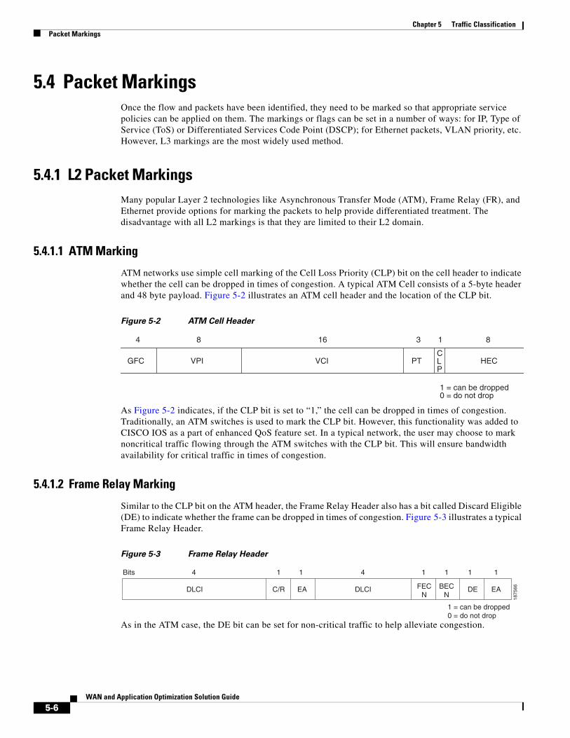
5.4 Packet MarkingsOnce the flow and packets have been identified, they need to be marked so that appropriate service policies can be applied on them. The markings or flags can be set in a number of ways: for IP, Type of Service (ToS) or Differentiated Services Code Point (DSCP); for Ethernet packets, VLAN priority, etc. However, L3 markings are the most widely used method.
5.4.1 L2 Packet MarkingsMany popular Layer 2 technologies like Asynchronous Transfer Mode (ATM), Frame Relay (FR), and Ethernet provide options for marking the packets to help provide differentiated treatment. The disadvantage with all L2 markings is that they are limited to their L2 domain.
5.4.1.1 ATM Marking
ATM networks use simple cell marking of the Cell Loss Priority (CLP) bit on the cell header to indicate whether the cell can be dropped in times of congestion. A typical ATM Cell consists of a 5-byte header and 48 byte payload. Figure 5-2 illustrates an ATM cell header and the location of the CLP bit.
Figure 5-2 ATM Cell Header
As Figure 5-2 indicates, if the CLP bit is set to “1,” the cell can be dropped in times of congestion. Traditionally, an ATM switches is used to mark the CLP bit. However, this functionality was added to CISCO IOS as a part of enhanced QoS feature set. In a typical network, the user may choose to mark noncritical traffic flowing through the ATM switches with the CLP bit. This will ensure bandwidth availability for critical traffic in times of congestion.
5.4.1.2 Frame Relay Marking
Similar to the CLP bit on the ATM header, the Frame Relay Header also has a bit called Discard Eligible (DE) to indicate whether the frame can be dropped in times of congestion. Figure 5-3 illustrates a typical Frame Relay Header.
Figure 5-3 Frame Relay Header
As in the ATM case, the DE bit can be set for non-critical traffic to help alleviate congestion.
GFC VPI VCI PTCLP
HEC
4 8 16 3 1 8
1 = can be dropped0 = do not drop
DLCI DLCI FECN
BECN
DE EAEAC/R
Bits 4 1 1 1 1 1 14
1 = can be dropped0 = do not drop
1875
66

5-7WAN and Application Optimization Solution Guide
Chapter 5 Traffic ClassificationPacket Markings
5.4.1.3 Ethernet Marking
The IEEE 802.1p standard provides traffic class expediting and dynamic multicast filtering. It enables Layer 2 switches to prioritize traffic. The 802.1p defines 3 bits in the header for classification, which helps classifying traffic into eight different traffic classes. It should be noted that 802.1p is an extension of 802.1Q standard and they work together. Figure 5-4 shows an Ethernet 802.1q frame and the TAG byte where the Priority bits are located.
Figure 5-4 Ethernet 802.1Q Frame
IEEE has put forth recommendations on various traffic types, corresponding traffic classes, and priorities to be used with 802.1p standard. They are listed in Table 5-1.
Preamble SFD DA SA TPI TAG Data CRCType/length
Bytes 7 7
7 1 12 Bits
6 6 2 2 2 48-1500 4
User Priority CPI Bits of VLAN ID (VID) to identify 4096 possible VLANS
1876
67
Table 5-1 Traffic Classes to Priority Mapping
Traffic Type Traffic class Priority
Bulk transfers, Games etc. Background 1
Less than 10 millisecond delay Voice 2
Less then 100 millisecond delay Video 3
Some important application Controlled Load 4
Best Effort for important users Excellent Effort 5
Ordinary LAN priority Best Effort 6
High requirement to get through to maintain and support the network infrastructure
Network Control 7

5-8WAN and Application Optimization Solution Guide
Chapter 5 Traffic ClassificationPacket Markings
5.4.2 L3 Packet MarkingsSimilar to Layer 2 headers, the IP header has fields that can be used to classify traffic into treatment groups. The most widely used L3 marking techniques are Type of Service (ToS) and DSCP. Figure 5-5 shows a typical IP header.
Figure 5-5 \IP Header
5.4.2.1 ToS
ToS was originally defined in RFC 791 and 795 and was further modified/updated by other RFCs like RFC 1122, RFC 1123, and RFC1349. Although the field has been there for quite sometime, it has not been widely used. Its use has been superseded by DSCP today. The ToS fields are shown in Figure 5-6:
Figure 5-6 ToS Fields
IP Precedence - Table 5-2 details the precedence bits and their possible values:
0-3 4-7 8-15 16-33
Version HeaderLength
Type of Service(TOS/DSCP
Total Length
Identification Flags Fragment
Time to Live Protocol Header Checksum
Source Address
Destination Address
Options
1866
8
Precendence Delay Throughput Reliability ECN ECN
Bits 3 1 1 1 1 1
0 = normal1 = low
0 = normal1 = low
0 = normal1 = low
1875
69Table 5-2 ToS Precedence Bits and their values
Binary Decimal Classification
000 0 Routine
001 1 Priority
010 2 Immediate
011 3 Flash
100 4 Flash Override
101 5 Critical

5-9WAN and Application Optimization Solution Guide
Chapter 5 Traffic ClassificationPacket Markings
• Delay - when set to 1, the packet requests low delay.
• Throughput - when set to 1, the packet requests high throughput.
• Reliability - when set to '1,' the packet requests high reliability.
5.4.2.1.1 ToS Byte
• IP precedence—three bits (P2 to P0)
• Delay, Throughput and Reliability—three bits (T2 to T0)
• ECN — two bits
5.4.2.2 DSCP
Differentiated Service Code Point (DSCP) was defined in RFC 2474 and RFC 2475. DiffServ (DS) has more priority levels than that of ToS because DS has more priority bits. DiffServ uses the same three most significant like ToS to define priority, but uses the next three bits to further refine them. DS fields are used to determine the per-hop behavior (PHB) of the packet. The following byte layouts illustrates the difference between ToS and DiffServ.
5.4.2.2.1 DiffServ Field
• DSCP—six bits (DS5-DS0)
• ECN—two bits
The ECN bits were not in the original DSCP RFCs. They were later added later by RFC 3168 to allow for congestion notification in the path.
RFC 2597 for DiffServ defines Assured Forwarding (AF) PHB that can be used by a service provider to provide different forwarding assurances based on different AF classes. There are four different AF classes each with three different drop probabilities.
110 6 Internetwork Control
111 7 Network Control
Table 5-2 ToS Precedence Bits and their values
Binary Decimal Classification
P2 P1 P0 T2 T1 T0 ECN ECN
DS5 DS4 DS3 DS2 DS1 DS0 ECN ECN

5-10WAN and Application Optimization Solution Guide
Chapter 5 Traffic ClassificationSummary
RFC 2598 for DiffServ defines Expedited Forwarding (EF) PHB. "The EF PHB can be used to build a low loss, low latency, low jitter, assured bandwidth, and end-to-end service through DS (Diffserv) domains. Such a service appears to the endpoints like a point-to-point connection or a “virtual leased line.” This service has also been described as “Premium service.” Codepoint 101110 is recommended for the EF PHB.
All the PHBs require vendor support to implement and not all vendors fully support them. Table 5-3 shows the guidelines for DSCP service classes as defined by RFC 4594. .
5.5 Summary Classification involves proper identification of different application flows and packets in the traffic and their appropriate marking. Once the packets are classified, the router can apply appropriate service policies for those packets. Typically, QoS is used to provide appropriate treatment to different traffic based o the configured policies. As was discussed earlier, each application has its own characteristics and requirements. With the limited WAN bandwidth, QoS policies help in providing different treatments for different traffic classes. Various QoS mechanisms such as Congestion Management, Congestion Avoidance, Traffic Policing/Shaping, and Link Efficiency exist that can be used to manage the WAN bandwidth.
5.6 References1. Classification Overview:
http://www.cisco.com/en/US/docs/ios/12_0/qos/configuration/guide/qcclass.html
Table 5-3 DSCP to Service Class Mapping
Service Class Name DSCP Name DSCP Values Application Example
Network Control CS6 110000 Network routing
Telephony EF 101110 IP telephony bearer
Signalling CS5 101000 IP telephony signalling
Multimedia Conferencing AF41, AF42, AF43 100010, 100100, 100110 H.323/V2 video conferencing (adaptive)
Real-Time Interactive CS4 100000 Video conferencing and interactive gaming
Multimedia Streaming AF31, AF32, AF33 011010, 011100, 011110 Streaming video and audio on demand
Broadcast Video CS3 011000 Broadcast TV and live events
Low-Latency Data AF21, AF22, AF23 010010, 010100, 010110 Client/server transactions, Web-based ordering
OAM CS2 010000 OAM & P
High-Throughput Data AF11, AF12, AF13 001010, 001100, 001110 Store and forward applications
Standard DF (CS0) 000000 Undifferentiated applications
Low-Priority Date CS1 001000 Any flow that has no BW assurance
5-11WAN and Application Optimization Solution Guide
Chapter 5 Traffic ClassificationReferences
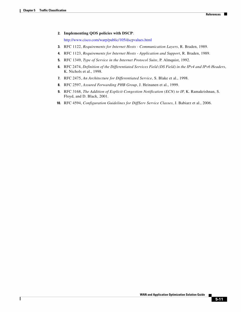
2. Implementing QOS policies with DSCP:
http://www.cisco.com/warp/public/105/dscpvalues.html
3. RFC 1122, Requirements for Internet Hosts - Communication Layers, R. Braden, 1989.
4. RFC 1123, Requirements for Internet Hosts - Application and Support, R. Braden, 1989.
5. RFC 1349, Type of Service in the Internet Protocol Suite, P. Almquist, 1992.
6. RFC 2474, Definition of the Differentiated Services Field (DS Field) in the IPv4 and IPv6 Headers, K. Nichols et al., 1998.
7. RFC 2475, An Architecture for Differentiated Service, S. Blake et al., 1998.
8. RFC 2597, Assured Forwarding PHB Group, J. Heinanen et al., 1999.
9. RFC 3168, The Addition of Explicit Congestion Notification (ECN) to IP, K. Ramakrishnan, S. Floyd, and D. Black, 2001.
10. RFC 4594, Configuration Guidelines for DiffServ Service Classes, J. Babiarz et al., 2006.

5-12WAN and Application Optimization Solution Guide
Chapter 5 Traffic ClassificationReferences