trademarks - skynet.beusers.belgacom.net/images/manuals/m748-11.pdf · - maximum 8mb frame buffer...
TRANSCRIPT

The information presented in this publication has been carefullychecked for reliability; however, no responsibility is assumed forinaccuracies.Specifications are subject to change without notice.
TrademarksPS/2,OS/2,IBM,PC/AT, and PC/XT are trademarks of InternationalBusiness Machines Corporation.
Intel, Celeron and Pentium® II/III are registered trademarks of IntelCorporation.
AMI is a trademark of American Megatrends Inc.
MS-DOS, Windows 3.1/95/98/NT, Direct Sound 3D and Direct Music areregistered trademarks of Microsoft Corporation
A3D is a registered trademark of Aureal Inc.
Sound Blaster is a registered trademark of Creative Technology, Ltd.
PC-cillin and ChipAwayVirus are registered trademarks of Trend Micro,Inc.
Copy right (C) 1999.All Rights Reserved.
M748MR, Version 1.1S6T/January 1999

Chapter 1: Introduction .......................................................................... 1Key Features ......................................................................................... 2
Unpacking the Mainboard & Static Electricity Precautions ................. 4
Chapter2: Hardware Configuration ...................................................... 6Mainboard Component Locations ........................................................ 7
CPU Installation ................................................................................... 8
CPU Speed Setting ......................................................................... 11
Memory Installation ............................................................................. 12
Jumper Settings .................................................................................... 12
JP2 - CMOS RAM Clear Selector ................................................. 12
ATX Functions & Connectors ............................................................. 13
PWR1 - ATX Power Connector ..................................................... 13
J6(21,22) - Power Button/Suspend Switch Connector ................... 13
Software Power-Off ....................................................................... 14
Alarm Wake On .............................................................................. 14
LAN/Modem Ring Wake On ..........................................................14
JP3 - Wake On LAN Connector ..................................................... 14
Keyboard Power On ....................................................................... 15
JP1 - Keyboard Power On Selector ................................................ 15
Connectors ........................................................................................... 16
PWR2 - AT Power Connector ........................................................ 16
KB1 - AT Keyboard Connector ......................................................16
COM1/2 - Serial Port #1/#2 ........................................................... 16
PRN1 - Parallel Printer Connector ................................................. 16
FDC1 - Floppy Disk Drive Connector ........................................... 16
IDE1/IDE2 - Primary/Secondary IDE Connectors ........................ 16
VGA1 - VGA Port Connector ........................................................ 17
J1 - ATX Form Card Connector ..................................................... 17
JP4 - CPU Fan Power Connector ................................................... 17
J6 - Case Connectors ...................................................................... 18
IR1 - InfraRed Connector .............................................................. 18
JP10 - PS/2 Mouse Pin-header Connector ..................................... 18
ii Contents

Onboard PCI Sound Pro ...................................................................... 19
J2/J4 - Analog Audio from CD-ROM Connectors ........................ 19
J3 - Sound and Game Connector ................................................... 19
J8 - Digital Audio Connectors ....................................................... 20
JP8 - SPDIF OUT Signal Selector ................................................. 20
J7 - Internal SPDIF IN Connector ................................................. 20
Notice for PCI Sound Pro application ........................................... 21
The 4 Speakers System .................................................................. 22
JP7 - Onboard Sound Pro Selector ................................................ 23
Modem Ready Option ......................................................................... 24
JP11 - Modem Module Selector .................................................... 24
JP9 - Modem DAA Module Connector ......................................... 24
Chapter3: BIOS Setup .......................................................................... 25
Entering BIOS Setup............................................................................ 26
Default.................................................................................................. 26
Load Optimal Settings.................................................................... 26
Load Best Performance Settings.................................................... 26
Setup Item ........................................................................................... 27
Standard CMOS Setup................................................................... 27
Advanced CMOS Setup................................................................. 28
Advanced Chipset Setup................................................................ 30
Power Management Setup.............................................................. 33
PCI / Plug and Play Setup.............................................................. 35
Peripheral Setup............................................................................. 37
H/W Monitor & CPU PnP Setup.................................................... 39
Change Supervisor Password......................................................... 40
Auto-Detect Hard Disks................................................................. 40
Save Settings and Exit.................................................................... 40
Exit Without Saving....................................................................... 40
Chapter4: SoftWare Driver .................................................................. 41
iii


This mainboard is a Xcel 2000 100MHz high-performanceModem Ready (needed chipset PCT789 on location U12and DAA module for Modem Ready) mainboard based onthe Slot 1 microprocessor, and provides CPU Plug and Playfeature for faster and easier CPU installation. Themainboard features highly flexible configurations and isfully IBM PC/AT compatible.
The mainboard uses a highly integrated Slot 1 chipset with3D video inside that is built-in a high performance 64-bit3D AGP Graphics Accelerator with 8MB frame buffershared from system memory. It supports the PCI/ISA andGreen standards, provides the Host/AGP bridge, and inte-grates all system control functions such as ACPI (AdvancedConfiguration and Power Interface). The ACPI providesmore energy saving features for the OSPM(OS DirectPower Management) function.
The mainboard has an onboard 3D PCI Sound Pro to meetPC98 Audio requirement and an optional Modem DAAmodule for internet access. It is also built-in HardwareMonitor circuit for abnormal CPU fan speed/temperature/voltages detection and its BIOS provides Trend’sChipAwayVirus to ensure the entire boot process virusfree.
Chapter 1Introduction

The advanced features of this mainboard include:
Supports Pentium® II 233~500MHz, Celeron 266~433MHz and Pentium® III (Katmai New Instruction) 450~500MHz CPUs.- supports both 66.6MHz and 100MHz FSB (Front Side Bus) .- provides CPU Plug and Play feature for faster and easier CPU installation.
Provides 3 DIMMs for 3.3V SDRAM memory modules.- supports a maximum size of 768MB system memory.
Provides 3 PCI and 1 ISA slots.
Onboard 2 IDE ports,- supports four IDE devices maximum.- supports PIO, Bus Master and Ultra DMA 33/66 operation modes.
Provides both AT/ATX power connectors and features of ATX power as follows:- Power Button/Suspend Switch, Keyboard Power On/Off (needs Win98 keyboard).- Alarm, LAN and Modem Wake On.
Onboard switching mode DC-DC Step Down Regulator.- complies with Intel VRM V8.2 specification.- Over-Voltage and Over-Current protection.
Onboard 64-bit 3D AGP Graphics Accelerator ,- AGP Ver2.0 spec. complicant and built-in 8-way/16-entry set- associative GART cache for AGP master.- maximum 8MB frame buffer share from system memory.- high resolution graphic modes up to 1600x1200.
Onboard PCI Sound Pro meets PC98' specifications,- full duplex playback and recording, built-in 16-bits CODEC.- HRTF 3D positional audio, supports both Direct Sound 3D® & A3D® interfaces, and support four channel speakers mode.- supports Windows 3.1/95/98 and Windows NT 4.0.- built-in 32 ohm earphone buffer and 3D surround.
Key Features2 Chapter 1

- supports MPU-401 Game/Midi port and legacy audio SB16.- downloadable Wave-table Synthesizer support Direct Music®.- Digital Audio Interface(SPDIF) IN/OUT up to 24-bit stereo 44KHz sampling rate voice and measured 120dB audio quality.- Stereo Mixer supports analog mixing from CD-Audio, Line-In, and digital mixing from voice, FM/Wave-table and digital CD- Audio.
Onboard Multi-I/O and Peripheral interface, include:- 1 floppy port with 1 Mb/s transfer rate.- 2 serial ports with 16550 compatible Fast UART.- 1 parallel port with EPP and ECP capabilities.- 2 USB ports & PS/2 keyboard/mouse ports.- 1 IR interface.
Built-in Hardware Monitor circuit,- detects CPU temperature/fan speed and current voltages.- supports Intel LANDesk Client Manager(LDCM ).
Optional Modem DAA module for communications,- supports V.90 upgradable, V.34, V.32bis, V.32, V.22bis, V.22, V.21, V.23, Bell212A, Bell103 communication standards.- supports Auto Fallback, Caller ID, and MNP 5, V.42bis data compression with 115200 compatible Virtual UART.- 16MB RAM, and Windows 95/98/NT 4.0 operating system are the minimum platform requirement.
Onboard 2M Flash ROM supports complete ACPI and Legacy PMU, and is fully compatible with PC97 and PC98.- provides Plug & Play function which detects the peripheral devices and expansion cards automatically.- provides Trend’s ChipAwayVirus to ensure the entire boot process is virus free, no installation and configuration worries.
Bundled AMI Desktop Client Manager, detect abnormal condition and thermal management through the network link or self care.Bundled PC-cillin98 (OEM) provides automatic virus protection for Windows 95/98 and the Internet.
Dimension: Baby AT Form Factor, 22cm(L) x 22cm(W).
Introduction 3

Unpacking the Mainboard & Static ElectricityPrecautions
4 Chapter 1
This mainboard package contains the following items:
1. The mainboard and the device drivers
2. This User’s Manual and AT cables
3. VGA and Sound/Game ribbon cables/bracket
4. Optional Modem DAA module and SPDIF IN cable
5. Optional ATX Form Card and Digital Audio ribbon
cables/bracket
The mainboard is easily damaged by static electricity.Follow the precautions below while unpacking or installingthe mainboard.
1. Do not remove the mainboard from its original packageuntil you are ready to install it.
2. Frequently ground yourself to discharge any static electriccharge that may build up in your body while working oninstallation and/or configuration. For example, you mayground yourself by grasping an unpainted portion of thesystem’s metal chassis.
3. Remove the mainboard from its anti-static packaging andplace it on a grounded surface, component side up.
4. Handle the mainboard by its edges or by the mountingbracket to avoid touching its components.
5. Check the mainboard for damage. If any integrated circuitappears loose, press carefully to seat it firmly in itssocket.
6. Do not apply power if the mainboard appears damaged. Ifthere is damage to the board contact your dealerimmediately.


Before you install the mainboard into the system chassis,you may find it convenient to first configure themainboard’s hardware. This chapter describes how to setjumpers and install memory modules, and where toattach components, however, the CMOS jumper is set onthe “Clear” position when this mainboard is shipped andyou need to set it to the “Normal” position in order forthe mainboard perform properly.
Chapter 2Hardware Configuration
Warning: Set JP2 to “Normal” position before setting otherjumpers or memory modules. This mainboard willnot function properly if you fail to do so.

7Hardware Configuration
Mainboard Component Locations
Figure 2-1. Mainboard Component Locations
DIM
M1
DIM
M2
DIM
M3
1
1
COM1
PCI1PCI2PCI3
JP4
IDE2
1
FDC1
PRN1
KB1
PWR2
PWR1
1
1
1
1
IDE1
1
1
1
1
2
2122
JP1
JP10IR1
VGA1
SLOT1
JP7
1JP2
1
JP11
1
1
COM2
1
J81
Chipset
JP3
I/O
+
Battery
J6
12
2625
J3
11
J1
J4
JP8
1
J7
J2
Chipset
PCtel
1JP9

Chapter 28
This mainboard supports Intel Pentium® II CPU by a Single Edge Contact(SEC) slot and a retention clip set which is fit for 3 different mechanical types of Intel CPU (SEPP, SECC and SECC2). The following drawing shows the retention clip set. It has been preinstalled before shipping to make the CPU installation easier for users. However, there are still a few more steps needed to complete the CPU installation, please refer to the followingprocedures.
CPU Installation

Installation Procedures Follow the following steps in order to install your intel Pentium® II properly.
Step 1: Make sure that the mainboard is set the same direction as the following drawing before doing any installation.
9Hardware Configuration
Chipset
I/O
+
Battery
Chipset

Step 2:There is one set of Slot1 Holder retention that was installed on your motherboard, and the two chutes of Holder retention are screwed in. Lift up both of the Holder chutes as shown in the following drawing.
Step 3:Flatten the two latches on the side of CPU. Insert the CPU into the Holder retention. Lock the two latches to secure the CPU.
Chapter 210
If Celeron CPU is installed on CPU card, then, continue the following step.

Step 4:After installing CPU card into the Holder retention, then push the retention locker downward to secure the CPU card as indicated in the following 2 drawings.
Hardware Configuration 11
CPU Speed SettingThis mainboard provides CPU Plug and Play technology,so that there is no need to do the CPU jumper setting. Enter the BIOS Setup and select CPU Plug and Play Setup. Choose the correct CPU speed to match your CPU installed.
However, if you need to change a CPU, follow the belowsteps:1. Power off system and unplug the power core.2. Install a new CPU to Slot1.3. Clear CMOS RAM (see Jumper Settings) or hold down the <Page Up> key and then power on the system.4. After power on the system, then enter the BIOS Setup to set the new CPU speed.Note: If the CPU speed is set incorrectly and fails to boot up the system, then repeat steps 1, 3, 4 again.����������

Chapter 212
This board lets you add up to 768MB of system memory through 3 DIMM sockets, as follows:
Memory Installation
Memory Module
DIMM1 4MB, 8MB, 16MB, 32MB, 64MB, 128MB, 256MB
DIMM2 4MB, 8MB, 16MB, 32MB, 64MB, 128MB, 256MB
DIMM3 4MB, 8MB, 16MB, 32MB, 64MB, 128MB, 256MB
System Memory = DIMM1 + DIMM2 + DIMM3
Notes: 1. Supports only 3.3V SDRAM DIMM modules. 2. The SDRAM must be installed in DIMM1 first, if onboard VGA is being used.�������
1
JP2Description
Normal
Clear CMOS (while shipping)
1
Jumper SettingsJP2 - CMOS RAM Clear SelectorThe battery on this mainboard is designed to retain the system configuration in CMOS RAM. In order to save the life of the battery, this jumper is set to "Clear CMOS" position when this board is shipped, therefore you need toset this jumper to "Normal" position before setting other system configuration.
Note: 1. Make sure this jumper is set to Normal mode before use. 2. Once you need to clear the CMOS, make sure your system is truned off and the power core is unplugged.
Chipset
I/O
+
Battery
Chipset
1
JP2
1
JP2

Hardware Configuration 13
ATX Functions & ConnectorsThis mainboard supports ATX power and ACPIspec. The ATX functions and connectors are described below, andwhich work with ATX power supply.
PWR1 – ATX Power Connector Connect the ATX power supply to this connector which provides all power for the mainboard.
J6(21,22) – Power Button/SuspendSwitch Connector Attach the ATX power button or suspend switch cable to this connector. In the AT power system, this connector will act as a suspend switch; In the ATX power system, this connector will be not only an ATX power button but a suspend switch as well. Details are described below: Turn the system back on by pushing the power button, and, if the system is already on, pushing the power button allows the system to be switched to the Suspend mode. However, if push and hold the power button for more than 4 seconds, then the system will be turned off completely. And, if the system is already in the Suspend mode, pushing the power button rapidly will turn on the system.
pin21,22 -Power Button
Chipset
I/O
+
Battery
Chipset
PWR1
12
2122
J6
12
2122
J6
PWR1

Chapter 214
Software Power-Off Follow the steps below to use the “Software Power-Off Control” function in Windows 95/98. 1. Click the START button on the Windows 95/98 task bar. 2. Select Shut Down The Computer to turn off the computer. The message “It is now safe to turn off your computer.” will not be shown when using this function.
Alarm Wake On If you want to autoboot the system at a certain time, set the RTC Alarm time properly and "Enabled" the option of RTC Alarm Power On and refer to BIOS Setup section.
LAN/Modem Ring Wake On While in soft-off/suspend state, if an external LAN/modem signal occurs, the system wakes up and can be remotely accessed. When using Modem Ring Wake On function make sure that the IRQ3 option is set to Monitor and the Ring On Power On option is set to Enabled. User must connect LAN card to the following connector and set the LAN Card Power On option to Enabled when using LAN Wake On function.
JP3 - LAN Wake On Connector Connect this connector to the LAN card that support ACPI specification.
1 5V Standby2 Ground3 Active High
JP3
Chipset
I/O
+
Battery
Chipset
JP3

Hardware Configuration 15
Note: Make sure that the system power can provide 720mAon +5VSB(+5V Standby) signal before using KeyboardPower On function.����
JP1Description
Enabled
Disabled(default)
1
1
Keyboard Power On Press the hot key to power on the system by keyboard. User must enter BIOS Setup to set Enabled to the Keyboard Power On option and to select the Stroke Keys Selected option for "Hot Key" in the Advanced Chipset Setup, and set the following jumper. If the keyboard that supports Windows 98 Key Power On function, you need to set ACPI Wakeup to the Stroke Keys Selected option.
JP1 – Keyboard Power On Selector This jumper is designed for the user to select Keyboard Power On function.
1JP1
Chipset
I/O
+
Battery
Chipset
1JP1

Chapter 216
ConnectorsAttach system components and case devices to themainboard via the mainboard connectors. A description ofeach connector follows.
Note: Make sure that the power is turned off before making any connection to the board.��
PWR2 – AT Power ConnectorKB1 – AT Keyboard ConnectorCOM1/2 – Serial Port #1/#2PRN1 – Parallel Printer ConnectorFDC1 – Floppy Disk Drive ConnectorIDE1/IDE2 – Primary/SecondaryIDE Connectors
PWR2
KB1
FDC1
1
IDE1
IDE2
1
1
PRN11
COM2COM111
Chipset
I/O
+
Battery
Chipset
1
COM1
IDE2
1
FDC1
PRN1
KB1
PWR2
1
1
1
IDE1
1
COM2

17Hardware Configuration
J1 – ATX Form Card Connector
Connect this connector to the ATX Form Card that come with the mainboard package. Which contains 2 USB(pin1-4,pin10-13), PS/2 Mouse(pin5-6,pin15-16) and InfraRed (pin7-9,pin17-18)connectors,
Chipset
I/O
+
Battery
Chipset
JP4
1
VGA11
1
J1
VGA1J1
JP4 – CPU Fan Power Connector
Connect CPU fan cable to this connector.
JP4Sensor
+12VGND
+5V 1Data - 2Data + 3
GND 4+5V 5
M CLK 6GND 7
NC 8+5V 9
10 +5V 11 Data - 12 Data + 13 GND 15 M Data16 GND 17 IR I18 IR O
VGA1 – VGA Port ConnectorConnect VGA cable/bracket to this connector.
R 1
B 3
GN
D 5
GN
D 7
Vcc 9
NC
11
H S
YN
C 1
3D
DC
CLK
15
2 G
4 N
C6 G
ND
8 G
ND
10 G
ND
12 D
DC
Data
14 V
SY
NC

Chapter 218
J6 - Case Connectors The case connectors contain: Speaker, Power LED, Keylock, Turbo LED, HDD LED, Reset Switch, and Power Button as following drawing.��
pin1, 3, 5, 7 – Speaker pin2, 4, 6 – Power LEDpin8, 10 – Keylock pin13, 14 – Turbo LEDpin15, 16 – HDD LED pin17, 18 – Reset Switchpin21, 22 – Power Button (refer to ATX Functions & Connectors section)
IR1 – InfraRed ConnectorThe mainboard provides a 5-pin Infrared connector for IRdevices. You must configure the setting of IR device throughthe Peripheral Setup in BIOS Setup section.
JP10 – PS/2 Mouse Pin-header ConnectorConnect PS/2 mouse pin-header cable to this connector for PS/2 mouse.
Chipset
I/O
+
Battery
Chipset
1
12
2122
JP10IR1
1
J6
1 +
5V
2 N
C3 IR
RX
4 G
ND
5 IR
TX
12
2122JP
10
IR1 1
J6

Onboard PCI Sound Pro
There is a onboard PCI Sound Pro for the 3D multimedia systems.
J3 - Sound and Game The board provides Line-In/Rear(see following The 4 Speakers System section), MIC(Microphone),Line-Out(Speaker) signals for audio I/O, and Game port(which is also used as the Joystick/MIDI port) signals.
J2/J4 - Analog Audio from CD-ROM ConnectorsConnect from “AUDIO” output of the CD-ROM driver tothese connectors. For Panasonic or compatible type ofCD-ROM, connect to J2 (pin signals assignment is G-L-G-R), and for Sony or compatible type of CD-ROM,connect to J4 (pin signals assignment is L-G-G-R).�
J41
J2
Chipset
I/O
+
Battery
Chipset
12
2625
J3
1
J4 J2
1
2
3
4
5
6
7
9
10
11
12
13
G Power
SWC
TIMB
TXD
TIMA
SWD
RXD
(L) Line IN
GND Line IN
MICP
GND
(L) Line OUT
14
15
16
17
18
19
20
21
22
23
24
25
26
G Power
SWA
TIMD
GND
GND (Game Port)TIMC
SWB
G Power
(R) Line IN
GND MIC
MIC IN
GND Line OUT
(R) Line OUT
(Sound Port)
J3
19Hardware Configuration

J8 - Digital Audio ConnectorConnect this connector to the Digital Audio ribbon cable/ bracket that contains 3 jacks for Aux IN, SPDIF IN and SPDIF OUT device. Aux IN is used as the second Line-in port. SPDIF IN is used to input the external digital audio. Connect SPDIF OUT to the AC3 Audio Amplifier or Mini-Disk to play, and set the following jumper to select 5V or 0.5V signal level for used device.
JP8 - SPDIF OUT Signal Level Selector
J7 - Internal SPDIF IN ConnectorConnect to “DIGITAL AUDIO” port of the CD-ROM drive by using the SPDIF/IN cable, which gives you the non-distortion digital audio from CD-ROM.
JP8Description
0.5V (default)
5V
Aux L 1
D In 5
D Out 7
J82 Aux R
4 GND
6 GND
8 GND
Chipset
I/O
+
Battery
Chipset
1
J81
JP8
1
J7
1
JP8
1
J7
Chapter 220
Notice that you should avoid to use the SPDIF IN jack and the internal SPDIF IN connector simultaneously. i.e. if oneof them is connected, you should unplug the other one.�

Hardware Configuration 21
1. Before you install the PCI Sound Pro drivers, make sure your Operating System has been installed, otherwise the PCI Sound Pro might be detect as "Other Device" by the device manager of your OS.
2. After the drivers install, if you wants to use Software Wave-Table drivers as MIDI output device, select MULTIMEDIA icon within CONTROL PANEL. Select MIDI page, and click on "C-media SoftMidi Synthesis(Win98)/Driver(Win95)" then click "OK" to confirm.
3. A Windows application named Audio Rack is provided within PCI Sound Pro drivers, which gives you control over all audio functions through a user interface as simple to use a home stereo system, we recommended you to use the System Mixer within Audio Rack to control the volume, recording device select and recording gain.
4. If you using devices that use Midi port as the control interface, you need to select MULTIMEDIA icon within CONTROL PANEL. Select MIDI page, and click on "CM8338 MPU-401"(Win98) or "CMI8338/C3DX PCI Audio External MIDI port"(Win95) then click "OK" to confirm.
5. See details of PCI Sound Pro manual within the CD attached with the mainboard.
Notice for PCI Sound Pro application

22 Chapter 2
The Four Speakers SystemOnboard Sound Pro provides 2 wave channels (front/rear), known as the 4 speakers system. When application programs via DirectSound® 3D or A3D® interface locate the sound sources to the listener's back, the two rear speakers will work to enhance the rear audio positional effect, so as to complement the insufficiency of using only two front speakers to emulate the audio effect. The following is the hardware installation and the software setups:
1. Speaker InstallationConnect the front pair speakers to the Line-out jack on the Sound port, and then, connect rear pair speakers to Line-in/Rear jack. The original Line-in can be moved to Aux-in.
2. Speaker PositionSet up your speakers similar to the following figure to get the best audio result.
3. Mixer SetupWhen user was setup the PCI Audio Application, there is a 4 speakers option in the Volume Control of the Mixer. Click on the 4 SPK icon to enable this option. This means that the rear speakers are connected to Line-in/Rear jack. However, in order to avoid hardware conflicts, DO NOT enable this option when Line-in/Rear jack is connected to other external Line-in sources. Turn on/off the output of the front speakers and adjust the volume of speakers to the same volume for the rear speakers.
4. DemoExecute the "Helicopter" demo within the C3D HRTF Positional Audio Demos of the PCI Audio Application. When the helicopter flies behind you, it means that the rear speakers are working properly.

Hardware Configuration 23
Set Up of 4 speakers
Rear Speakers
Front Speakers
(Sound Port)
Line-in/Rear Line-out
Speaker Speaker
SpeakerSpeakerMonitor
JP7 - Onboard Sound Pro SelectorSet this jumper to disable the onboard PCI Sound.
1
JP7Description
Disabled
Enabled (default)
1
1
JP7
Chipset
I/O
+
Battery
Chipset
1
JP7

Chapter 224
Modem Ready Option The Modem Ready mainboard has a built-in modem controller with optional Modem DAA module which provide the communication features.
JP9 – Modem DAA Module ConnectorPlug the Modem DAA module to this connector for externalconnection, its figure is as follows:
1
JP11Description
Enabled
Disabled(default)
1
1
JP11
JP11 - Modem Module SelectorSet this jumper to enable the modem function when you installed the Modem DAA module.
Chipset
I/O
+
Battery
Chipset
1
JP11
JP9
1 MCLK3 FRA-SY5 SCLK7 RIN-WAK
11 SDO13 SDI15 RST
GND 2GND 4GND 6
AUX 3V 8HOOK 10
RIN 12AUX 5V 14
MUTE 16
JP9
1
Plug in

Chapter 3BIOS Setup
This chapter explains how to configure the mainboard’sBIOS setup program. The setup program provided withthe mainboard is the BIOS from AMI.
After you have configured the mainboard and haveassembled the components, turn on the computer andrun the software setup to ensure that the systeminformation is correct.
The software setup of the system board is achievedthrough Basic Input-Output System (BIOS)programming. You use the BIOS setup program to tell theoperating system what type of devices are connected toyour system board.
The system setup is also called CMOS setup. Normally,you need to run system setup if either the hardware is notidentical with information contained in the CMOS RAM,or if the CMOS RAM has lost power.
Note: Hold down the <End> key then power on to reboot thesystem when installing newer BIOS into thismainboard .

26 Chapter 3
Entering BIOS Setup
To enter the BIOS Setup program:1. Turn on or reboot the system. A screen appears with
a series of diagnostic checks.
2. When “Hit <DEL> if you want to run SETUP”appears, press the <DEL> key to enter the BIOSsetup program. The following screen appears:
Standard CMOS setup for changing time, date, hard disk type, etc.
AMIBIOS SIMPLE SETUP UTILITY - VERSION 1.1X(C)1998 American megatrends, Inc. All Rights Reserved
Standard CMOS Setup
Advanced CMOS Setup
Advanced Chipset Setup
Power Management Setup
PCI/Plug and Play Setup
Load Optimal Settings
Load Best Performance Settings
Peripheral Setup
H/W Monitor & CPU PnP Setup
Change Supervisor Password
Auto-Detect Hard Disks
Save Settings and Exit
Exit Without Saving
Esc: Quit ↑ ↓ → ←: Select Item (Shift) F2: Change Color F5: Old ValuesF6: Optimal values F7: Best performance values F10 : Save&Exit
3. Use your keyboard to choose options. Modify systemparameters to reflect system options. Press Alt-H forHelp.
Default
Every option in the BIOS Setup contains two defaultvalues: Best default and the Optimal default value.
Load Optimal SettingsThe Optimal default values provide optimum systemsettings for all devices and system features.
Load Best Performance SettingsThe Best default values provide best performance settingsfor all devices and system features, however dependingon the devices used, these settings are not recommend forlong hours of work load.

BIOS Setup 27
Setup Items
Standard CMOS SetupChoosing the item from the BIOS Setup main menu. AllStandard Setup options are described in this section.
AMIBIOS SETUP - STANDARD CMOS SETUP(C)1998 American Megatrends, Inc. All Rights Reserved
Date (mm:dd:yy) : Tue Nov 24,1998Time (hh:mm:ss) : 18:44:46 LBA Blk PIO 32Bit TYPE SIZE Cyln Head WPcom Sec Mode Mode Mode ModePri Master : Auto OnPri Slave : Auto OnSec Master : Auto OnSec Slave : Auto On
Floppy Drive A : 1.44MB 31/2Floppy Drive B : Not Installed
Month: Jan - Dec ESC : Exit Day: 01 - 31 ↑ ↓ : Select Item Year: 1901 - 2099 PU/PD/+/- : Modify (Shift)F2 : Color
Base Memory : 640 Kb Other Memory : 384 KbExtended Memory : 123 Mb
Total Memory : 124 Mb
Date/Time Select the Date/Time option to change the dateor time. The current date and time aredisplayed. Enter new values through thedisplayed window.
Pri Master;Pri Slave;Sec Master;Sec Slave
Choose these icons to configure the hard diskdrive named in the option. When you click onan icon, the following parameters are listed:Type, LBA/Large Mode, Block Mode, 32BitMode, and PIO Mode. All parameters relate toIDE drives except Type. Choose the Typeparameter and select Auto BIOS automaticallydetects the IDE drive parameters and displaysthem. Choose on LBA Mode and choose On toenable support for IDE drives with capacitiesgreater than 528MB. Click on Blk Mode andchoose On to support IDE drives that use BlkMode. Click on 32Bit Mode and click on On tosupport IDE drives that permit 32-bit accesses.

28 Chapter 3
Floppy DriveA; B
Choose the Floppy Drive A or B icon to specifythe floppy drive type. The settings are 360KB51/4", 1.2MB 51/4", 720KB 31/2", 1.44MB 31/2", or2.88MB 31/2".
Advanced CMOS SetupChoosing the item from the BIOS Setup main menu. AllAdvanced Setup options are described in this section.
Quick Boot Enabled1st Boot Device IDE-02nd Boot Device Floppy3rd Boot Device ARMD-HDD4th Boot Device DisabledTry Other Boot Devices YesS.M.A.R.T. for Hard Disks DisabledBootUp Num-Lock OnFloppy Drive Swap DisabledFloppy Drive Seek DisabledPS/2 Mouse Support EnabledPrimary Display AbsentPassword Check SetupBoot to OS/2 > 64MB DisabledInternal Cache EnabledSystem BIOS Cacheable CachedVideo,32K Shadow CachedC800,16K Shadow DisabledCC00,16K Shadow DisabledD000,16K Shadow Disabled
D400,16K Shadow DisabledD800,16K Shadow DisabledDC00,16K Shadow Disabled
ESC : Quit ↑ ↓ → ←: Select ItemF1 : Help PU/PD/+/– : ModifyF5 : Old Values (Shift)F2 : ColorF6 : Load BIOS DefaultsF7 : Load Setup Defaults
AMIBIOS SETUP - ADVANCED CMOS SETUP(C)1998 American Megatrends, Inc. All Rights Reserved
Quick Boot 1st, 2nd, 3rd, 4th Set these options to select the boot
Set this option to Enabled to permit BIOSto boot within 5 seconds.
Try Other Boot
Choose Yes to search other boot devices to
Devices boot up the system when all the options in
S.M.A.R.T for Hard
This option allows you to utilize the
Disks S.M.A.R.T function of HDDs.

BIOS Setup 29
Boot Up Num-Lock Set this option to turn on Num Lock keywhen the system is powered on.
Floppy Drive Swap This option allows you to swap floppydrives between A: and B:.
Floppy Drive Seek Choose Enabled or Disabled. Disabledprovides a faster boot and reduces thepossibility of damaging the heads.
PS/2 Mouse Support When this option is set to Enabled, BIOSsupports a PS/2-type mouse.
Password Check This option specifies the type of BIOSpassword protection that is implemented.The settings are:Setup: The password prompt appears
only when an end user attemptsto run BIOS Setup.
Always: A password prompt appearsevery time the computer ispowered on or rebooted.
The password does not have to be enabled.
Primary Display Set this option to select the primary displaysubsystem in the computer.
Boot to OS/2 >64MB
You need to set this option to Enabledwhen using the OS/2 operating systemwith installed DRAM which is greater than64MB.
Internal Cache
Set this option to enable or disable the internal cache.
System BIOSCacheable
BIOS always copies the system BIOS fromROM to RAM for faster execution. Set thisoption to Enabled to permit the contents ofthe F0000h RAM memory segment to bewritten to and read from cache memory.

30 Chapter 3
Video, 32K Shadow;C800, 16K Shadow;CC00, 16K Shadow;D000, 16K Shadow;D400, 16K Shadow;D800, 16K Shadow;DC00, 16K Shadow
Disabled: The specified ROM is notcopied to RAM.
Enabled: The contents of the ROM areaare not only copied from ROMto RAM for faster execution,the contents of the RAM areacan be written to or read fromcache memory.
Cached: The contents of the ROM areaare copied from ROM to RAMfor faster execution.
Advanced Chipset SetupChoose the item from the BIOS Setup main menu. AllChipset Setup options are then displayed and aredescribed in the following section:
Trend ChipAway Virus EnabledShare Memory Size DisabledDRAM Auto Configuration ManualSDRAM Speed 8nsRAS# Pulse when Refresh 6TRAS# Precharge Time 3TRAS to CAS Delay 3TRefresh Queue Depth 0SDRAM CAS Latency 3TGraphic Win Size 64MVGA Frame Buffer USWC Disabled16Bit I/O Recovery Time 5 BUSCLK8Bit I/O Recovery Time 5 BUSCLKISA Bus Clock 7.159MHzUSB Function EnabledUSB Function for DOS Disabled
ESC : Quit ↑ ↓ → ←: Select ItemF1 : Help PU/PD/+/– : ModifyF5 : Old Values (Shift)F2 : ColorF6 : Load BIOS DefaultsF7 : Load Setup Defaults
AMIBIOS SETUP - ADVANCED CHIPSET SETUP(C)1998 American Megatrends, Inc. All Rights Reserved
Trend ChipAwayVirus
Choose Enabled to activate the TrendChipAwayVirus function.
Share Memory Size
Set this option to select VGA frame buffersize that share from system memory.
DRAM Auto Set this option to enable the AutoConfiguration Configuration of DRAM timing.

BIOS Setup 31
SDRAM Speed Set this option to select the SDRAM speedtiming when the DRAM Auto Configurationset to Manual.
RAS# Pulse whenRefresh
Set this option to select the proper RAS#pulse when DRAM refreshes.
RAS Precharge Set this option to select the proper SDRAMTime RAS precharge time.
RAS to CAS Delay
Set this option to select the proper delay timeof SDRAM RAS to CAS.
Refresh Queuey Set this option to select the proper RefreshDepth Queue depth.
SDRAM CASLatency
Set this option to select the proper SDRAMCAS Latency.
Graphics Win Size Set this option to select the memory-mapped. Use the default setting.
VGA Frame Buffer Set this option to enable USWC for the USWC VGA frame buffer.
16, 8 Bit I/ORecovery Time
Set these options to specify the length of adelay inserted between consecutive 16-bit or8-bit I/O operations.
ISA Bus Clock
Set this option to select the proper ISA Busclock.
USB Function
Set this option to enable the system BIOSUSB (Universal Serial Bus) functions.

32 Chapter 3
USB Function forDOS Keyboard Power On
Set this option to enable the passive releaseon the USB. Set this option to enable the KeyboardPower On function, refer to the ATX Functions & Connectors section for more information,
BIOS Setup 33
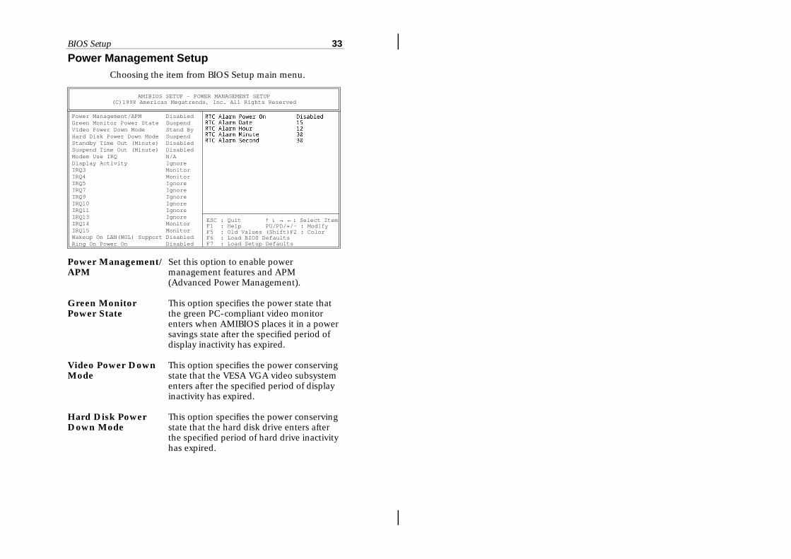
Power Management SetupChoosing the item from BIOS Setup main menu.
Power Management/APM DisabledGreen Monitor Power State SuspendVideo Power Down Mode Stand ByHard Disk Power Down Mode SuspendStandby Time Out (Minute) DisabledSuspend Time Out (Minute) DisabledModem Use IRQ N/ADisplay Activity IgnoreIRQ3 MonitorIRQ4 MonitorIRQ5 IgnoreIRQ7 IgnoreIRQ9 IgnoreIRQ10 IgnoreIRQ11 IgnoreIRQ13 IgnoreIRQ14 MonitorIRQ15 MonitorWakeup On LAN(W OL) Support DisabledRing On Power On Disabled
ESC : Quit ↑ ↓ → ←: Select ItemF1 : Help PU/PD/+/– : ModifyF5 : Old Values (Shift)F2 : ColorF6 : Load BIOS DefaultsF7 : Load Setup Defaults
AMIBIOS SETUP - POWER MANAGEMENT SETUP(C)1998 American Megatrends, Inc. All Rights Reserved
Power Management/APM
Set this option to enable powermanagement features and APM(Advanced Power Management).
Green MonitorPower State
This option specifies the power state thatthe green PC-compliant video monitorenters when AMIBIOS places it in a powersavings state after the specified period ofdisplay inactivity has expired.
Video Power DownMode
This option specifies the power conservingstate that the VESA VGA video subsystementers after the specified period of displayinactivity has expired.
Hard Disk PowerDown Mode
This option specifies the power conservingstate that the hard disk drive enters afterthe specified period of hard drive inactivityhas expired.

34 Chapter 3
Standby Time out(Minute)
This option specified the length of systeminactivity while in Full power on state.When this length of time expires, thecomputer enters Standby power state.
Suspend Time Out(Minute)
This option specified the length of aperiod of system inactivity while inStandby state. When this length of timeexpires, the computer enters Suspendpower state.
Display Activity;IRQ3, 4, 5, 7, 9, 10, 11, 13, 14, 15 Wakeup On LAN Su; Set these options to enable the signal of LAN/Ring On Power On modem to resume the system with ATX power.
When set to Monitor, these options enableevent monitoring on the specified hardware interrupt request line and the computer is in a power saving state, BIOS watches for activity on the specified IRQ line. The computer enters the full on power state if any activity occurs.
RTC Alarm PowerOn
Set this option to enable the RTC Alarm toresume the system with ATX power.
RTC Alarm Date;RTC Alarm Hour;RTC Alarm Minute;RTC Alarm Second
Set these options to specify the RTCAlarm time on Date/Hour/Minute/Second.

BIOS Setup 35
PCI/Plug and Play SetupChoose the item from the BIOS Setup main menu.
Plug and Play Aware O/S YesPrimary Graphics Adapter PCIPCI VGA Palette Snoop DisabledAssign IRQ for VGA NoDMA Channel 0 PnPDMA Channel 1 PnPDMA Channel 3 PnPDMA Channel 5 PnPDMA Channel 6 PnPDMA Channel 7 PnPIRQ3 PCI/PnPIRQ4 PCI/PnPIRQ5 PCI/PnPIRQ7 PCI/PnPIRQ9 PCI/PnPIRQ10 PCI/PnPIRQ11 PCI/PnPIRQ14 PCI/PnPIRQ15 PCI/PnPReserved Memory Size Disabled
Reserved Memory Address C8000
ESC : Quit ↑ ↓ → ←: Select ItemF1 : Help PU/PD/+/– : ModifyF5 : Old Values (Shift)F2 : ColorF6 : Load BIOS DefaultsF7 : Load Setup Defaults
AMIBIOS SETUP - PCI / PLUG AND PLAY SETUP(C)1998 American Megatrends, Inc. All Rights Reserved
Plug and PlayAware OS
Set this option to Yes if the operation system inthis computer is aware of and follows the Plugand Play specification. Currently, onlyWindows 95 is PnP-aware.
Primary GraphicsAdapter
Set this option to select onboard AGP or PCI VGA card for primary graphics adapter.
PCI VGA PaletteSnoop
When this option is set to Enabled, multipleVGA devices operating on different buses canhandle data from the CPU on each set of paletteregisters on every video device. Bit 5 of thecommand register in the PCI deviceconfiguration space is the VGA Palette Snoopbit.
Assign IRQ forVGA
This option is used to allocate IRQ to PCI VGA.Recommendation is set to No.

36 Chapter 3
DMA Channel 0,1, 3, 5, 6, 7
These options specify the bus that the specifiedDMA channel is used on.
IRQ3, 4, 5, 7, 9, These options specify the bus that the specified10, 11, 14, 15 IRQ line is used on. These options allow you to
reserve IRQs for legacy ISA adapter cards.
Reserved Memory These options are designed to be used for Size/Address reserving memory/memory address for the IO
card.
.

BIOS Setup 37
Peripheral SetupChoose the item from the BIOS Setup main menu.
OnBoard FDC EnabledOnBoard Serial Port1 3F8h/COM1OnBoard Serial Port2 2F8h/COM2OnBoard IR Port Disabled Ir Duplex Mode FullOnBoard Parallel Port 378h Parallel Port Mode Normal Parallel Port IRQ 7 Parallel Port DMA N/AOnBoard IDE Both
ESC : Quit ↑ ↓ → ←: Select ItemF1 : Help PU/PD/+/– : ModifyF5 : Old Values (Shift)F2 : ColorF6 : Load BIOS DefaultsF7 : Load Setup Defaults
AMIBIOS SETUP - PERIPHERAL SETUP(C)1998 American Megatrends, Inc. All Rights Reserved
OnBoard FDC This option enables the FDC (Floppy DriveController) on the motherboard or auto detectsthe FDC.
OnBoard SerialPort1
This option specifies the base I/O port addressof serial port 1.
OnBoard SerialPort2
This option specifies the base I/O port addressof serial port 2.
OnBoard IR Port
This option specifies the onboard IR port.Disabled: The normal serial port 2 mode is
being used.HPSIR/ASKIR: The serial port2 will be redi-
rected to support IR function when this option is set to HPSIR or ASKIR.
IR Duplex Mode This option is to specify the Duplex mode ofSerial Port 2.
OnBoard ParallelPort
This option specifies the base I/O port addressof the parallel port on the motherboard.

38 Chapter 3
Parallel PortMode
Depends on the type of your external devicewhich connects to this port to choose Normal,EPP, or ECP mode.
Parallel Port IRQ This option specifies IRQ to parallel port.
Parallel PortDMA
This option is only available if the setting of theParallel Port Mode option is EPP/ECP.
OnBoard IDE This option specifies the channel used by theIDE controller on the motherboard.

BIOS Setup 39
H/W Monitor & CPU PnP SetupChoose this item from the BIOS Setup main menu.
CPU Speed 400MhzCPU Base Frequency 100MhzCPU Multiple Factory 4.0XSDRAM Frequency 100Mhz-=System Hardware Monitor=- Temperature 72C/161F Current FAN Speed 0 RPM +12.000V 11.750 V +5.000V 4.921 V +3.300V 3.250 V Vcore 2.203 V
ESC : Quit ↑ ↓ → ←: Select ItemF1 : Help PU/PD/+/– : ModifyF5 : Old Values (Shift)F2 : ColorF6 : Load BIOS DefaultsF7 : Load Setup Defaults
AMIBIOS SETUP - CPU PLUG AND PLAY SETUP(C)1998 American Megatrends, Inc. All Rights Reserved
CPU Speed This option is displayed only.
CPU Base Select a correct CPU frequency to match your Frequency CPU, that includes 60, 66, 75, 83, 95, 100 MHz.
CPU Multiple Select a correct CPU factory to match your CPU,Factory that includes 2, 2.5, 3, 3.5, 4, 4.5, 5, 5.5, 6, etc.
SDRAM Frequency Set this option to select the SDRAM frequency to match your SDRAM.
-=System Hardware Monitor=-
Temperature;Current FAN
These options are displayed only to show thestatus of the system hardware.
Speed; +12.000V; +5.000V; +3.300V; Vcore

40 Chapter 3
Change Supervisor Password This item lets you configure the system password which is required every time when an attempt is made to enter the Setup program. The password cannot be longer than six characters. If you want to disable the password which has already been set, please follow the steps as follows: 1. Press the <Del> key to enter BIOS Setup. 2. Key in the current password then enter the BIOS setup program. 3. Choose the Change Supervisor Password item. 4. Key in the current password to change the password. 5. Then, press <Enter> key for new password. (It means to disable the password, while the <Enter> key insteads of the new password.) 6. Press any key to exit the Change Supervisor Password item, and then press <F10> key to save and exit BIOS setup program. Note: Keep a safe record of the new password. If you forget or lose the password, the only way to access the system is to clear CMOS memory by holding down the <End> key then powering on to reboot the system.
Auto-Detect Hard Disks If your system has an IDE hard drive, you can use this utility to detect its parameters and automatically enter them into the Standard CMOS Setup. This utility will autodetect up to four IDE devices.
Save Settings and Exit Select this item to save the values entered during the current session and then exit the BIOS setup program.
Exit Without Saving Select this item to exit the BIOS setup program without saving the values which has been entered during the current session.

Chapter 4SoftWare Driver
The CD came with the package is free of charge andincludes all our products’ drivers and the path of thismainboard’s drivers and utilities are listed below:
❏ Modem Driver for Windows 95/98(CD-ROM): \Modem\Driver\Win95&98\Setup.exe
❏ VGA Driver Path(CD-ROM): \VGA\M748vga\
❏ USB Driver for Windows 95(CD-ROM): \USB\Eusbsupp\Usbsupp.exe;(CD-ROM): \USB\Cusbsupp\Cusbsupp.exe forChinese Windows95
❏ PCI Sound Driver Path(CD-ROM): \SOUND\PCISoundPro\
❏ BIOS Update Utility (CD-ROM): \UTILITY\AMIfl807.exe
❏ Bundled PC-cillin Path(CD-ROM): \PC-cillin\
❏ Bundled ADCM Path(CD-ROM): \AMIADCM\