tractor plans
TRANSCRIPT
8/8/2019 Tractor Plans
http://slidepdf.com/reader/full/tractor-plans 1/7
IT WON'T take long to figure the needsfor this tractor on your farm. That prob-lem will immediately take care of itself when you get the tractor built, for Farm-ette is just chore-boy size and it's fasterthan any team of horses. So far as its usesare concerned you can take it from there.Power from Farmette's 7-hp. air-cooledengine is taken off the engine crankshaft byflat belt to a 4-speed truck transmission andthrough this to a cut-down rear axle takenfrom a 1934 Chevrolet car. Of course, anysuitable rear axle can be used, including alight truck axle. Positive clutching actionis obtained by an idler pulley running on
the slack side of the flat-belt drive from en-
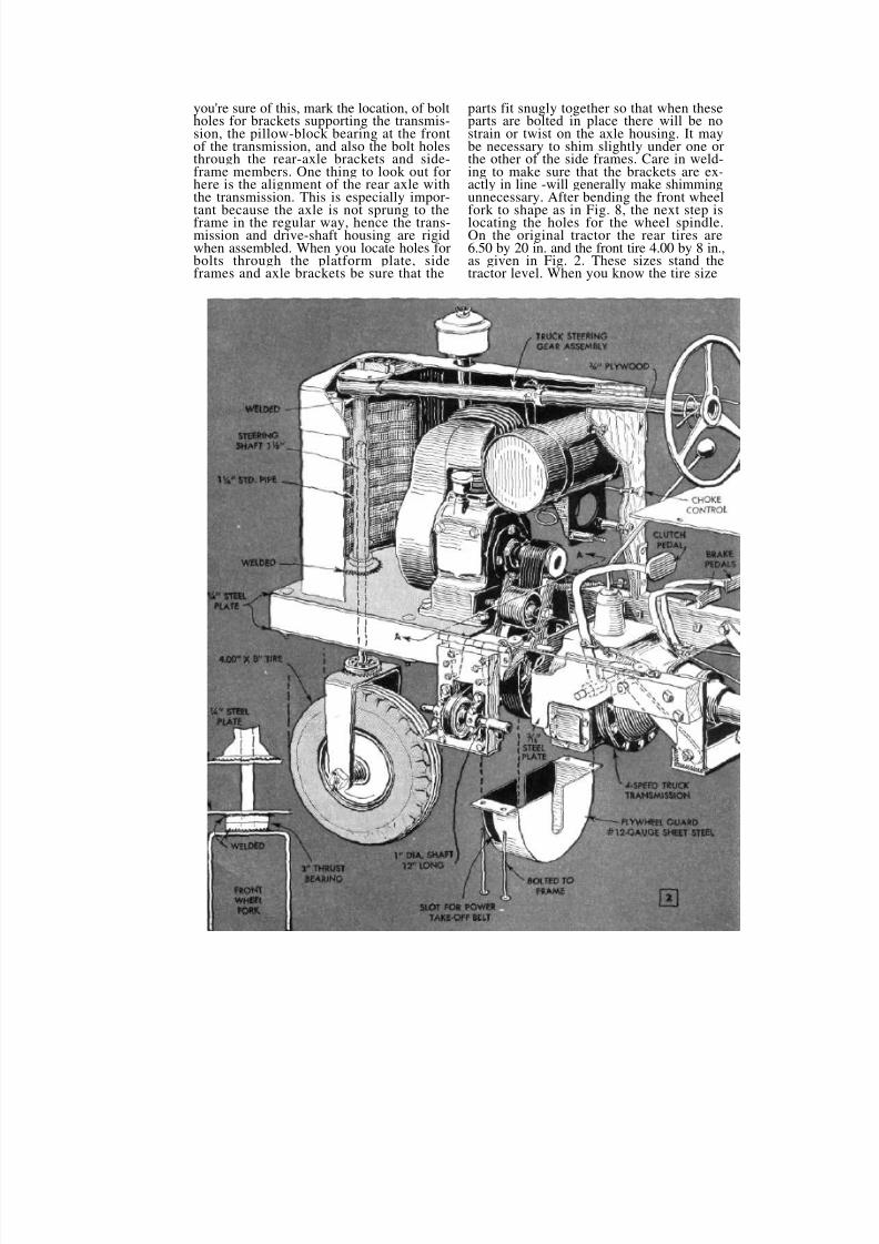
gine to transmission. The idler pulley is ac-tuated by a pedal, the arrangement givingsmooth foot-clutch control of the tractor.The pedal works against tension springsattached to the frame and to the idler-pul-ley yoke as in Pig. 3. Provision is made foradjusting the spring tension, which deter-mines the tension on the belt when theclutch is engaged. In Fig. 3 notice also thatessentially the same clutching arrange-ment is used in controlling the power take-off. This consists of a short shaft with V-pulley mounted between bearings. Thewhole assembly is bolted to a hinged brack-et. Movement is controlled by a rod carry-ing a compression spring, one end of whichbears against an adjustable collar. The free
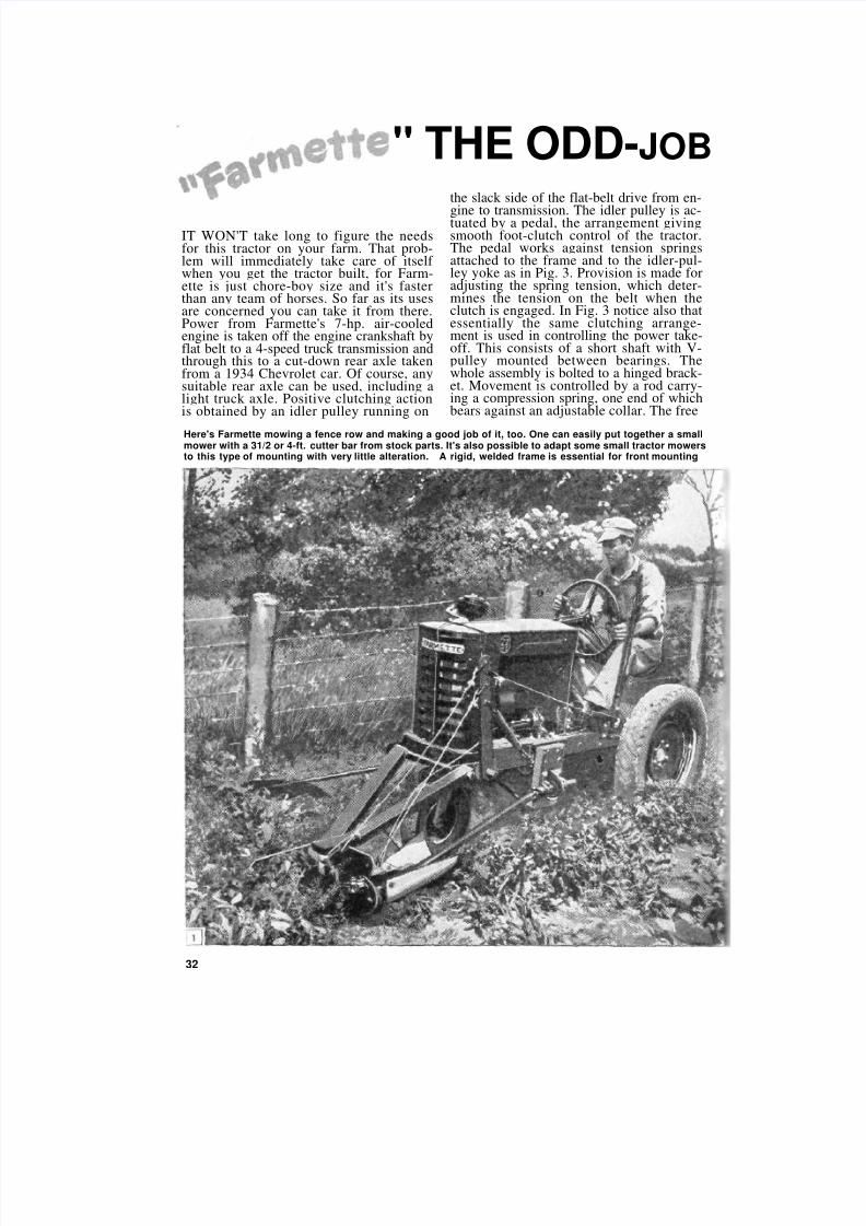
Here's Farmette mowing a fence row and making a good job of it, too. One can easily put together a smallmower with a 31/2 or 4-ft. cutter bar from stock parts. It's also possible to adapt some small tractor mowersto this type of mounting with very little alteration. A rigid, welded frame is essential for front mounting
" THE ODD-JOB
32
8/8/2019 Tractor Plans
http://slidepdf.com/reader/full/tractor-plans 2/7
TRACTOR
Small jobs that tie up big tractors at
busy times cost money for extra fuel
and extra man-hours. That's where a
nimble, pint-sized riding tractor like
Farmette :omes in. Farmette is
narrow enough to slip between rows
of standing corn or pass through a
footpath gate, and it's ideal for
mowing fence rows and plowing snow
end of the rod passes through a hole drilledin a bracket piece as shown. A wire cable,passing through an awning pulley on thebracket, is attached to the adjustable collar.
The free end of the cable is hooked to a con-:rol lever near the driver's seat. Moving thelever swings the power take-off assemblyinward toward the tractor frame, slacken-ing the V-belt. This whole driving assem-bly and clutch mechanism is shown clearlyin the perspective view, Fig. 4. Speed rangeis from 1 to about 20 miles per hour.
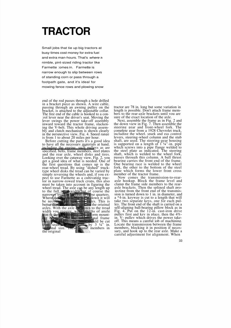
Before cutting the parts it's a good ideato have all the necessary materials at hand,including the engine, such pulleys as arespecified, belts, frame members, steel platesand the rear axle, wheel disks and tires.Looking over the cutaway view, Fig. 2, youget a good idea of what is needed. One of the first questions that comes up is therear-wheel tread. By using "dished" truck-
type wheel disks the tread can be varied bysimply reversing the wheels and, if you ex-pect to use Farmette as a cultivating trac-tor in narrow-rowed truck crops, this alsomust be taken into account in figuring thewheel tread. The axle can be any length upto the full tread width but of course thenarrower tread is handier in close quarters.Where the axle housing is cut down it willbe necessary to turn new axles. This isbetter than cutting and welding the originalaxles. With the axle cut down to the treadwidth you require, weld lengths of angleiron to the axle housing. These form mount-ing brackets for the longitudinal framemembers, Fig. 2. The latter should be cutfrom seasoned oak, 2 ¼” by 3 ¼” in.
sectional size. These frame members inthe original
tractor are 78 in. long but some variation inlength is possible. Don't attach frame mem-
bers to the rear-axle brackets until you aresure of the exact location of the axle.Next, assemble the frame as in Fig. 2 and
the down view in Fig. 7. Then assemble thesteering gear and front-wheel fork. Thecomplete gear from a 1928 Chevrolet truck,including the wheel, spark and gas controllevers, steering-wheel column and the stubshaft, are used. The steering-gear housingis supported on a length of 1 ¼”-in. pipewhich screws into a pipe flange welded tothe steel plate as indicated. The steeringshaft, which is welded to the wheel fork,passes through this column. A ball thrustbearing carries the front end of the frame.One bearing race is welded to the wheelfork, the other to the bottom of the steel
plate which forms the lower front crossmember of the tractor frame.Now comes the transmission-to-rear-
axle hookup. Block the frame level andclamp the frame side members to the rear-axle brackets. Then the splined shaft pro- jecting from the front end of the transmis-sion is turned down to 1 in. in diameter, anda *4-in. keyway is cut to a length that willtake two separate keys, one for each pul-ley. The front end of the shaft is carried on aself-aligning ball-bearing pillow block as inFig. 4. Put on the 12-in. cast-iron drivepulley first and key in place, then the 4%-in. V- pulley which drives the power take-off. This means a careful job of machining.Locate the transmission between the framemembers, blocking it in position if neces-sary, and hook up to the rear axle. Make acareful adjustment for alignment. When
33
8/8/2019 Tractor Plans
http://slidepdf.com/reader/full/tractor-plans 3/7
you're sure of this, mark the location, of boltholes for brackets supporting the transmis-sion, the pillow-block bearing at the frontof the transmission, and also the bolt holesthrough the rear-axle brackets and side-frame members. One thing to look out forhere is the alignment of the rear axle withthe transmission. This is especially impor-tant because the axle is not sprung to theframe in the regular way, hence the trans-mission and drive-shaft housing are rigidwhen assembled. When you locate holes forbolts through the platform plate, sideframes and axle brackets be sure that the
parts fit snugly together so that when theseparts are bolted in place there will be nostrain or twist on the axle housing. It maybe necessary to shim slightly under one orthe other of the side frames. Care in weld-ing to make sure that the brackets are ex-actly in line -will generally make shimmingunnecessary. After bending the front wheelfork to shape as in Fig. 8, the next step islocating the holes for the wheel spindle.On the original tractor the rear tires are6.50 by 20 in. and the front tire 4.00 by 8 in.,as given in Fig. 2. These sizes stand thetractor level. When you know the tire size

8/8/2019 Tractor Plans
http://slidepdf.com/reader/full/tractor-plans 4/7
measure and drill holes in the front-wheelfork for the 'wheel spindle. The nut on thespindle should be cotter-pinned as shown.This last step puts the frame on wheels andleaves the engine mounting, hood andgrille and other small parts yet to be madeand assembled. High-speed air-cooled en-gines of the type used on the original trac-
tor generally are self-contained units withfuel tank, air cleaner and other parts eitherbuilt in or attached directly to the engineitself. In order to get the engine properlypositioned over the transmission drive pul-ley it will be necessary, on most engines of
8/8/2019 Tractor Plans
http://slidepdf.com/reader/full/tractor-plans 5/7
Above and below are views of the simple clutch assemblyand power take-off drive. Clutch is pedal operated and isnothing more than an idler pulley which serves the dual pur-pose of belt tightener and clutch. Releasing pressure of theidler allows the flat belt to slip, thus stopping the tractor
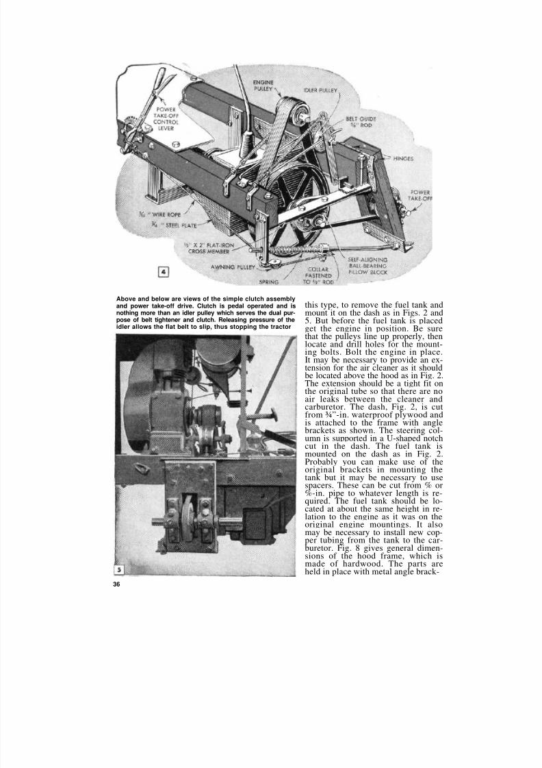
this type, to remove the fuel tank andmount it on the dash as in Figs. 2 and5. But before the fuel tank is placedget the engine in position. Be surethat the pulleys line up properly, thenlocate and drill holes for the mount-ing bolts. Bolt the engine in place.It may be necessary to provide an ex-tension for the air cleaner as it shouldbe located above the hood as in Fig. 2.The extension should be a tight fit onthe original tube so that there are noair leaks between the cleaner andcarburetor. The dash, Fig. 2, is cutfrom ¾”-in. waterproof plywood andis attached to the frame with anglebrackets as shown. The steering col-umn is supported in a U-shaped notchcut in the dash. The fuel tank ismounted on the dash as in Fig. 2.Probably you can make use of theoriginal brackets in mounting thetank but it may be necessary to usespacers. These can be cut from % or%-in. pipe to whatever length is re-quired. The fuel tank should be lo-cated at about the same height in re-lation to the engine as it was on theoriginal engine mountings. It alsomay be necessary to install new cop-per tubing from the tank to the car-buretor. Fig. 8 gives general dimen-sions of the hood frame, which ismade of hardwood. The parts areheld in place with metal angle brack-
36

8/8/2019 Tractor Plans
http://slidepdf.com/reader/full/tractor-plans 6/7
ets as shown. Hood and grille are of sheet metal and a clean, neat job of rorming these parts adds much to theappearance of the tractor. Unless, of course, you have facilities for work-ing sheet metal you'll want to takethis job to your local tinsmith.
The idler pulley which runs on thedrive belt serves the two-fold pur-pose of maintaining the proper ten-sion on the belt and providing theclutching action when starting thetractor under load. Use a pulley fit-ted with oilless bushings. The pul-ley should run on a hollow shaft pro-
vided with a pressure grease fitting.The drive belt should be of full-grain leather running with the hairside next to the drive pulleys. Toavoid pounding of the idler pulley thelacing should be made carefully sothat it will be flat. After the new beltlias been in use a few hours it willbe necessary to adjust the idler-pul-ley tension springs to compensate forstretch of the belt. The idler supportarms are mounted on a short crossshaft, one end of which is inserted ina hole drilled in the transmission sup-port as in Fig. 2. The other end of theshaft is carried in an angle bracketwelded to the pillow-block bearingsupport as in Fig. 4. Collars hold bothshaft and arms in position. Note thebelt guide in Fig. 4. Next comes thepulley, or flywheel guard, Fig. 2.This is made from 12-gauge sheetsteel, welded, and it is bolted directlyto the tractor frame. Be sure the

8/8/2019 Tractor Plans
http://slidepdf.com/reader/full/tractor-plans 7/7