tracing optimization of real time protocols in ims - ip ... · iona ca multe dintre acestea se afla...
TRANSCRIPT

Tracing optimization of real time
protocols in IMS - IP Multimedia Subsystems
PhD thesis
“Politehnica” University Timişoara Electronics and Telecommunications Engineering
2012
PhD Student Eng. Marin Mangri
Scientific Coordinator
Prof. Dr. Eng. Miranda Monica Naforniţă
Day to sustain the thesis: …………………………..

- 2 -
Preface
This thesis was conducted within the team led by Professor Doctor Engineer
Monica Nafornita, whose scientific quality and pedagogical contributed greatly to the completion of this thesis.
The final decision to choose this thematic and the finalization of this work was possible only with help, exhortations, advices, requirements, and availability
manifested throughout the entire period of preparation of the thesis, received from the Professor Doctor Engineer Monica Nafornita ,to whom I am taking the chance to express now my entire gratitude .
Many thanks are addressed to the management and to all colleagues of Telefonica Germany who through kindness, friendship and scientific expertise has encouraged the realization of this thesis.
Many thanks are addressed to my wife and my daughter Miruna for moral
support and help offered with love, without which this thesis completed at this time
would not have been possible. The author is grateful to all teachers from the Faculty of Electronics and
Telecommunications of the "Politehnica" University of Timisoara, who he had as
teachers during this period and that contributed to his scientific preparation. München 10.2012 Marin Mangri

- 3 -
Mangri, Marin
Tracing optimization of real time protocols in IMS - IP Multimedia
Subsystems
Teze de doctorat ale UPT, Seria X, Nr. YY, Editura Politehnica, 200Z, 121
pagini, 37 figuri, 4 tabele.
Cuvinte cheie: Keywords; IMS,ICS,SIP, IP,LTE,Release, Convergence, PS,MEGACO, Correlation, Identifier, Trace, TerminationID, SCTP,TCP,UDP, Mediagateways, Media Gateway Controller , BSSAP and ISUP traces on TDM,PaCo; User Plane; Control Plane; PDP context; User Identifiers; tracing;
traffic,Probe,xDR, Rezumat-I
La inceputul tezei am prezentat evolutia și tendințele din telecomunicațiile mobile ale ultimilor ani. Incepand din 1999 pana astazi și -au facut apariția nu mai puțin de opt releas-uri ca : Rel 99, Rel 4 ,Rel 5, Rel
6, Rel 7, Rel 8, Rel 9,Rel 10 și Rel 11 ce va fi finalizat in acest an. Putem menționa ca multe dintre acestea se afla deja implementate in
rețelele actuale urmand ca in scurt timp Rel 9 si Rel 10 sa isi facă
deasemena aparitia in lumea reala, ceea ce subliniaza dinamicitatea și importanța acestui domenium intr-o lume aflata in plin process de globalizare.
Obervând tendințele si situatia reala din retelele de Telecomunicatii si
IT, se poate considera, ca atat din punct de vedere teoretic căt si practic, direcțiile de dezvoltare sunt deja definite si anume: Convergența Rețelelor (Network Convergence)
&
All over IP network Toate acestea insa, asa cum am aratat mai sus , în cadrul și în conformitate cu specificațille facute ale ultimilor releas-uri, au ca tema centrala IMS (IP Multimedia Subsystem), iar ca central telecom protocolul SIP (SIP-SessionInitiationProtocol). Acest nou mediu de telecomunicații se va baza pe doua concepte de baza si
anume:
ICS (IMS Centralized Services) concept & FMC (Fixe-Mobile Convergence) concept.
Putem spune ca aceste doua concepte menționate mai sus vor avea o mare importanta in cadrul implementarillor viitoare conducand la atingerea țelurilor privind convergența rețeletor si a serviciilor de telecomunicații.
Acest process deja în derulare va solicita în opinia noastră o refacere și o regândire a tuturor celorlalte activități componente si subdomenii din telecomunicații.
Pentru a putea lua toate măsurile corespunzătoare necesare asigurari calitatii rețelor si serviciilor ICS avem nevoie de o regandire eficienta in primul rand a domeniului - management-ului de retea.

- 4 -
Mangri, Marin
Tracing optimization of real time protocols in IMS - IP Multimedia
Subsystems
Teze de doctorat ale UPT, Seria X, Nr. YY, Editura Politehnica, 200Z, 121
pagini, 37 figuri, 4 tabele.
Cuvinte cheie: Keywords; IMS,ICS,SIP, IP,LTE,Release, Convergence, PS,MEGACO, Correlation, Identifier, Trace, TerminationID, SCTP,TCP,UDP, Mediagateways, Media Gateway Controller , BSSAP and ISUP traces on TDM,PaCo; User Plane; Control Plane; PDP context; User Identifiers;
tracing; traffic,Probe,xDR, Rezumat-II
O posibilitate de a atinge acest obiectiv ar putea fi Network Management Unified [21].
De la începutul studiului nostru am identificat ca o componentă
flexibilă foarte importanta (in cadrul managementul unificat al rețelelor) si anume sistemul de Tracing. Am putea spune că sistemele de Tracing ale interfețelor de rețea și ale protocoalelor telecom vor ocupa un loc foarte
important si anume: The equipment trace “provides very detailed information at call level
on one or more specific mobile(s). Trace plays a major role in activities such as determination of the root cause of a malfunctioning mobile, advanced
troubleshooting, optimization of resource usage and quality …“[35]. Acesta va ajuta fiecărui operator de IMS/ICS de a identifica
problemele de funcționare ale rețelelor si serviciilor existente, pentru a verifica și de a îmbunătăți continuu noile implementări .
Mă refer aici, de exemplu, la efectuarea de traces E2E (End to End) între diferitele tehnologii (3GPP și non-3GPP), protocoale și interfețe diferite și pentru a corela E2E această informație diferită.
In acelasi timp pe baza unui sistem de Tracing, păstrand insa intactă aplicatia sa inițiala de tracer, se pot implementa „open CSA” platform ce pot duce la o analizare multi dimensionala a serviciilor, rețelelor, problemelor
tipice grupurilor de utilizatori si pana la nivel de analiza fiecărui utilizator in parte. Acest lucru ofera posibiltatea unei analize pe verticala plecând de la o analiză typica de PM bazată pe KI/KPI si duce la o analiză profundă si
detaliată de tip analiză de potocol. Cu o extindere a tracing-CSA platform, bazată pe un sistem de
raportare si alarming in timp real se poate obține un tool unic si puternic, păstrand toate caracteristcile FLM&optimization tipice unui tracing sistem si aducând „on top” -in plus noua componentă de PM.
Metoda de tracing, analizarea interfețelor și protocoalelor E2E (End-to-End) vor da posibilitatea de a păstra implementările rețelelor si serviciile
în conformitate cu specificațiile standard si a realiza o analiză profundă de tip analiză de protocol, iar noua componenta PM va asigura flexibilitatea si viteaza de reacție tipice acesteia.

- 5 -
Mangri, Marin
Tracing optimization of real time protocols in IMS - IP Multimedia
Subsystems
Teze de doctorat ale UPT, Seria X, Nr. YY, Editura Politehnica, 200Z, 121
pagini, 37 figuri, 4 tabele.
Cuvinte cheie: Keywords; IMS,ICS,SIP, IP,LTE,Release, Convergence, PS,MEGACO, Correlation, Identifier, Trace, TerminationID, SCTP,TCP,UDP, Mediagateways, Media Gateway Controller , BSSAP and ISUP traces on TDM,PaCo; User Plane; Control Plane; PDP context; User Identifiers; tracing;
traffic,Probe,xDR, Rezumat-III
Pe baza acestei noi platfome -CSA care dispune de toate interfețele in/out necesare, se poate ajunge la o integrare de tip CEM&Cloud ori se poate ajunge la o extindere a platformei in aceasta directie.
Primul capitol prezintă o evoluție succintă a specificațiilor din domeniul rețelelor de telecomunicații, de la GSM la IMS, subliniind astfel dinamicitatea, direcția de dezvoltare si de evoluție a acestui domeniu.
In același timp aici, putem observa de asemenea complexitatea noi evoluții, fenomen ce produce prezența absolut obligatorie a unor tool-uri puternice ce pot oferi o analiză multidemiseonală rapida de tip orizontal si o analiza profunda de tip vertical.
Conținutul celui de-al doilea capitol, se referă la câteva concepte și viziuni ale managementu-lui de rețea cu accent pe partea de rețele IMS. Aici am prezentat o scurta analiza a specificațiilor 3GPP dedicate domeniului de tracing si a noilor concepte de network management ajungand la a prezenta avantajele de utilizare a unui alt tip de tracing sistem, un altul decat cel bazat pe specificatiile 3GPP mentionate (in acest capitol), tracing sistem descris mai târziu în capitoul trei unde vom prezenta si principalele
probleme si metode de folosire ale acestuia. In capitolul al treilea se prezintă provocarea principală a
platformei de tracing bazatä pe utiliazarea probelor/analizoarelor pasive, ne-
intrusive având rolul de a colecta unu la unu informația de pe link-urile CP sau UP aflate sub monitorizare, de a stoca și in acelasi timp de a genera in format text "Data-Record" ce contin in format redus principalele informații
conținute intr-un call, event, tranzactie(dialog, sesiune) și inserarea lor intr-o baza de date centralizată, de unde tracing operatorul sa le poată accesa si folosi pentru scopul propus, după ce acestea au fost procesate, corelate și adaptate conform applicație de utilzare. Plecănd de la prezentarea generală a celor trei planuri distincte a IMS/ICS : • Transpor layer –IP-CAN (IP – ConnectivityAcces Netork) • Control Session-IMS (Core)
• Services Control –AS(Appication Servers),

- 6 -
Mangri, Marin
Tracing optimization of real time protocols in IMS - IP Multimedia Subsystems
Teze de doctorat ale UPT, Seria X, Nr. YY, Editura Politehnica, 200Z, 121
pagini, 37 figuri, 4 tabele.
Cuvinte cheie: Keywords; IMS,ICS,SIP, IP,LTE,Release, Convergence, PS,MEGACO, Correlation, Identifier, Trace, TerminationID, SCTP,TCP,UDP,
Mediagateways, Media Gateway Controller , BSSAP and ISUP traces on TDM,PaCo; User Plane; Control Plane; PDP context; User Identifiers; tracing; traffic,Probe,xDR, Rezumat-IV am identificat principala problema de rezolvat si anume problema datorata traficului excesiv a UP din Transpor layer –IP-CAN (IP – ConnectivityAcces
Netork) și a carui QoS se dorește a fi asigurată. O data identificata problema de tracing am continuat cu sugerarea solutiilor pentru asigurarea tracing-ului corespunzator. In faza ulterioara am continuat cu implementarea si dezvoltarea unei „CSA on
top-solution” Am continuat a analiza CP&UP-Mobil Broadband traffic (Control Plane&
User Plane-a IP-CAN) si cu luarea în considerare a tuturor componentelor
necesare cum ar fi raportarea în timp real, alarmarea in „real time", toate acestea în directa legătură cu „drill down tracing" - pentru a permite o analiza profundă a interfețelor și protocoalelor aflate sub analiză mergănd pana la analiza E2E folosind intra si inter protocol-corelation concept. Altfel formulat am prezentat un concept de analiza in plan vertical și orizontal a traficului CP si UP(High Traffic) pentru Transpor layer –IP-CAN (IP –
ConnectivityAccesNetork) a IMS. Odata rezolvate problemele de aici, din IP-CAN, celelalte planuri prezente in IMS Control Session (IMS Core) și Services Control –AS(Application Servers) nu sunt altceva decăt o extindere a soluțiilor aplicate deja aici in CP; cu specificul dat insa de cunoașterea și implementarea telecom-procols prezente in fiecare plan in parte.
Astel ca am continuat cu prezentarea unor propuneri de solutionare, a problemelor specifice in capitolul patru.
În capitolul patru se prezintă câteva metode și modalități de realizare optimala a tracing-ul E2E și analizarea protocoalelor pornind de la înțelegerea profundă a noilor protocoale, funcționalitățile rețelelor si propunerea unor solutii pentru asigurarea: Punctelor te monitorizare Tracing-ului si stabilitati sistemelor de tracing in Mobile BroadBand Deciphering of protocol interfaces- unde este cazul
Corelarea operațiilor si protocalelor ce nu prezintă necesarele "Permanent User-Identifiers "
Capitolul cinci prezinta contribuțiile și concluziile acestei teze reflectate cel mai bine de capitole trei si patru mentionand totodata si ideea
the Unified-Permanent-Tracing-Tool.

- 7 -
INTRODUCTION.............................................................................................8
1 CHAPTER-TELECOM NETWORKS FROM GSM TO IMS...........................10
1.1 SHORT INTRODUCTION OF 3GPP RELEASES (START UMTS ).............................12 1.1.1 Release99 .................................................................................... 12 1.1.2 Release 4 ..................................................................................... 14 1.1.3 IMS-IP Multimedia Subsystem and introduction of REL5,6&7 ............... 16 1.1.4 IMS-IP Multimedia Subsystem, LTE, REL8, REL9, REL10 and REL11 ..... 24 1.1.5 The Unified Multi Services Network – ICS “IMS centralized Services” ... 31 1.1.6 IMS Calls-Flow examples ................................................................ 34
2 CHAPTER - NETWORK MANAGEMENT...............................................46 2.1 NETWORK MANAGEMENT SUB-DOMAINS.....................................................46 2.2 IMS-NETWORK MANAGEMENT END TO END................................................50 2.2.1 Tracing Systems tool ..................................................................... 52 2.2.2 Justification concept of One network one Tracing system .................... 56 3 CHAPTER - TRACING SYSTEM AND CSA............................................58
3.1 CSA PLATFORM BASED ON A TRACING SYSTEM.............................................61 3.2 DETAILS ABOUT WORKING MODE OF THE NEW CSA........................................64 3.3 CSA SOLUTION FOR ICS-IMS CENTRALIZE SERVICES....................................67 3.4 TRACING SYSTEM AS A CSA AT WORK.......................................................70 4 CHAPTER–TRACING SYSTEMS’ PROTOCOLS-INTERFACES OPTIMIZATIONS............................................................................81 4.1 MONITORING POINTS..........................................................................81
4.2 DECIPHERING OF PROTOCOL INTERFACES....................................................83 4.3 TRACING PACKET-CORE FOR CP AND UP TRAFFIC [37]...................................85 4.3.1 IP-CAN interfaces .......................................................................... 87 4.3.2 Tracer using Static and Dynamic Filters ........................................... 89 4.3.3 New Method of Tracing ................................................................... 91 4.4 TRACING METHOD WITH INTRA AND INTER PROTOCOLS CORRELATION-OF THE PROTOCOLS
AND OPERATIONS WITHOUT PERMANENT SUBSCRIBERS IDENTIFIERS [38], [39]........95
4.4.1 MEGACO Protocol .......................................................................... 95 4.4.2 Megaco Correlation Method ............................................................. 97 4.4.3 Network and traces ..................................................................... 100 4.4.4 The correlation ways .................................................................... 104 4.4.5 Conclusion-correlation without having the permanent users identifiers 106 4.4.6 Other way to obtain the (users) permanents identifiers .................... 107
5 CHAPTER-CONTRIBUTIONS AND CONCLUSIONS..............................108 ABBREVIATIONS..........................................................................112 REFERENCES...............................................................................118

- 8 -
Introduction
This thesis is starting, pointing to the tendency of mobile
telecommunication. Today from now, for a long period of time, the telecom network’s way and direction are already defined: Network Convergence
&
All over IP network That all, within and under IMS (IP Multimedia Subsystem) network, having SIP as central protocol (SIP-Session InitiationProtocol) This new telecommunications environment will be based on: ICS (IMS Centralized Services) concept
&
FMC (Fixe-Mobile Convergence) concept.
These both concepts will have a big importance, in the future telecom world implementations. This already on going process will request in our opinion, a rebuilding and rethinking of all others telecom activities, components and sub domains.
To be able to take the right actions and to keep under control the new ICS
network, we need anyway an efficiently network management domain implementation.
A possibility to reach this target could be, the Unified Network Management [21].
From the beginning of our study, we have identified like a very powerfully and important flexible component (within the Unified Network Management
architecture) the Tracing-System. And now here, we could tell that, the Tracing-Systems of network interfaces
and protocols will occupy a very important place. The equipment trace “provides
very detailed information at call level on one or more specific mobile(s). Trace plays a major role in activities such as determination of the root cause of a malfunctioning mobile, advanced troubleshooting, optimization of resource usage and quality …“[35]. That will help each IMS operator to identify the problems, to verify and
improve continually the implementations of their networks. I am referring here for example at tracing E2E (End to End) between different technologies (3GPP and non-3GPP), different protocols and interfaces, and to correlate end to end this different information.
The method of tracing, and E2E (End-to-End) analysis of interfaces and protocols will give the possibility to keep the implementations under standard specifications, even this very important segment of network management “Tracing
of Interfaces and Protocols” is not yet fully standardised( after our opinion).

- 9 -
First chapter presents a succinct evolution of telecom networks from GSM to IMS (based on the already specified ways) highlighting the dynamicity of the
telecommunication domain. The content of second chapter is related to the few concepts and visions of
Network Managements with focusing on the IMS networks side. The third chapter is presenting the main provocation of the tracing
platform starting from IP-CAN (IP Connectivity Access Network), CP&UP (Control Plane & User Plane) taking in consideration all components like real time reporting,
alarming Performances managements, all these linked with the drill down- till to the
deeper analyzing of interfaces and protocols, through the traces having the intra and inter protocol correlation using the concept of E2E analyzing.
In chapter four we are presenting the few methods and ways to realize the E2E tracing and protocols analyses, starting from deeper understanding of new protocols and networks functionality.
The chapter five contents the contributions and conclusions of this thesis.

Chapter-Telecom networks from GSM to IMS
- 10 -
1 Chapter-Telecom networks from GSM to IMS
Mobile networks have gone through a major transition in the last past 20
years. First generation systems (1G) offered basic services, on speech and speech-related services. Second generation systems (2G) added data services and some supplementary services. The third generation (3G) is now enabling faster data rates and various multimedia services [4]. Now it is a fast convergence of fixed and
mobile networks as the developing of mobile devices. They are always-on and always-connected application devices. This redefines applications that are no longer isolated entities exchanging information only with the user interface, but peer-to-peer entities which facilitate sharing: shared browsing, shared two-way radio session, etc. The concept of being connected will be redefined; dialing and talking will became a narrow subset of networking and the ability to establish a peer-to-peer connection between the new Internet Protocol (IP) enabled devices is the key
required condition. The IP connectivity capability is offered only in isolated and single-service provider environement in the Internet. We need a global system, the IP Multimedia Subsystem (IMS) that allows applications to establish peer-to-peer or
peer-to-content connections easily and securely. IMS – see Figure 1.1 – is a global, acces-independent and standard based IP connectivity and service control architecture that enable various types of multimedia services to end-users using common Internet-based protocol [8].
Figure-1.1 IMS Network
IP-CAN - IP Connectivity Access Network QoS - Quality of Services
IMSCore
lP-CAN
SIP SIP
Application Server
Server
Q0S
Traffic Bearer
m
Media Flows
m
Short Introduction of 3GPP Releases
- 11 -
GSM (Global System for Mobile Communications) was defined by ETSI (European Telecommunications Standards Institute) during the 1980s and 1990s.
ETSI also defined GPRS (General Packet Radio Service) network architecture. The last GSM-only standard was produced in 1998, and in the same year the 3GPP (Third Generation Partnership Projet) was founded by standardization bodies from Europe, USA, China, Japan and South Korea to specify 3G mobile systems, as a successor for GSM (Global System for Mobile communications) the UMTS (Universal Mobile Telecommunications System). An extended concept of “GSM networks” 4G
(fourth generation) network represents the next step in the evolution of mobile
systems. After Release 1999, Release 2000 started to include All-IP that was later
renamed IMS. The developing of IMS was not complete at the end of year 2000, therefore Release 2000 was split into Rel 4 and Rel 5. Finally, 3GPP Rel5 introduced the IMS, a standardized acces-independent IP-based architecture which interworks with existing voice and data networks for both fixed and mobile users [3, 5, 6]. IMS is the most suitable to meet expectations for service quality, reliability and
availability when moving from existing CS telephony services to IP-based LTE (Long Term Evolution) services (the greatest differences between LTE and UMTS lie in the air interface, UMTS is a Wideband CDMA (Code Division Multiple Access)-based system, while LTE is a scalable OFDMA (Orthogonal Frequency-Division Multiple Access) system. IMS is able to simultaneously serve broadband wired and LTE wireless networks opening the path to service convergence. Almost each year
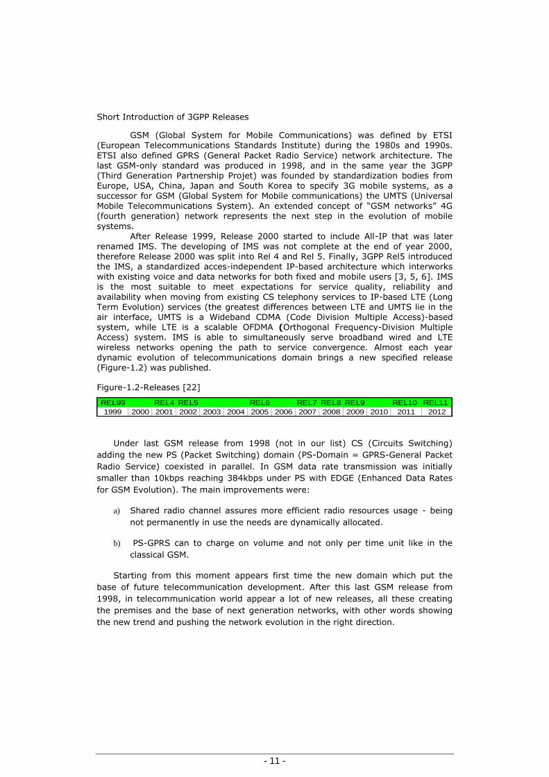
dynamic evolution of telecommunications domain brings a new specified release (Figure-1.2) was published.
Figure-1.2-Releases [22]
REL99 REL4 REL5 REL6 REL7 REL8 REL9 REL10 REL11
1999 2000 2001 2002 2003 2004 2005 2006 2007 2008 2009 2010 2011 2012
Under last GSM release from 1998 (not in our list) CS (Circuits Switching)
adding the new PS (Packet Switching) domain (PS-Domain = GPRS-General Packet
Radio Service) coexisted in parallel. In GSM data rate transmission was initially
smaller than 10kbps reaching 384kbps under PS with EDGE (Enhanced Data Rates
for GSM Evolution). The main improvements were:
a) Shared radio channel assures more efficient radio resources usage - being
not permanently in use the needs are dynamically allocated.
b) PS-GPRS can to charge on volume and not only per time unit like in the
classical GSM.
Starting from this moment appears first time the new domain which put the
base of future telecommunication development. After this last GSM release from
1998, in telecommunication world appear a lot of new releases, all these creating
the premises and the base of next generation networks, with other words showing
the new trend and pushing the network evolution in the right direction.

Chapter-Telecom networks from GSM to IMS
- 12 -
1.1 Short Introduction of 3GPP Releases (start UMTS )
1.1.1 Release99
Release 99 represents the introduction of UMTS (Universal Mobile Telecommunication System):
a) Frozen in 12.1999. b) New type of AN (Access Network), the UTRAN (UMTS Terrestrial Radio Access Network), with the minimum impact in to GSM/GPRS Core Network (CN)
infrastructure. c) It is also “High-speed GSM” based on WCDMA and ATM (FDD and TDD) d) Adopt all useful GSM R-99 services like video mobile telephony e) USIM (Universal Subscriber Identity Module) f) New Protocols like RANAP radio network access protocol and new interfaces like IuCS and IuPS. In the CS domain, the differences between GSM and UMTS are not particularly relevant (GSM's A interface is quite similar to the UMTS' Iu_CS
interface) whereas in the PS domain, the UMTS' Iu_PS offers "connections" (called "Iu Bearers") contrarily to GSM's Gb interface [22] . Based on TS 23.002 V4.8.0 (2003-06) the UMTS Network Architecture is (see
Figure-1.3): Figure-1.3 UMTS Network Architecture
MSCVLR
SGSN
RNC1
BSC
IuCs
A
Gb
IuPS
PSTN_Legacy
Gs
InternetInternet
PS_Domain(Data)
CS_Domain(Voice)
NodeB
IuB
AbisBTS
USIM
SIM
MS or UE Domain
Uu
Um
RNC2
Iur
HLR
IN ….
GGSN
DNS …
G-MSC
IN-intelligent network; MSC-Mobile Switching Center; G-MSC-Gateway MSC; VLR-Visitor Location Register; BTS-Base Transceiver Station; BSC -Base Station Controller; NodeB -UMTS base stations; RNC-Radio Network Controller; SGSN - Serving GPRS Support Node; GGSN-Gateway GPRS Support Node; DNS-Domain Name System; HLR-Home Location Register; Uu and Um-air interfaces; Abis & IuB interfaces CP&UP (Control Plane& User Plane); For other interfaces the UP is
represented using interrupted line; IuCS, IuR, IuPs,RNC- interfaces and entities

Short Introduction of 3GPP Releases
- 13 -
specific to UMTS; Gs-Interface between SGSN and MSC-VLR - it is not mandatory depend on implementation of LA and RA; MS-Mobile Station; UE-User Equipment.
Broadband communications will play an important role with UMTS.
Multimedia applications will be added to the voice transmission: videoconferencing, exploring the Internet or document sharing. For these we need a data link technology able to handle CS and PS traffic respectively synchronous and asynchronous traffic. In UMTS Release’99 ATM was selected to perform this task.
UMTS specified four new interfaces: Uu, Iub, Iur and Iu [14 to 19]. The air interface Uu contains 3 layers: -L1, the physical layer responsible for data transmission through interface. -L2, the data link layer divided in four sub layers:
i) L2/MAC (Medium Access Control) responsible for mapping the logical channels into physical ones and for priority handling of UEs (User Equipments),
ii) L2/RLC (Radio Link Control) responsible for positive or negative acknowledgement of data transfer, establishment of RLC connections, transparent data transfer, QoS settings, etc., iii) L2/PDCP (Packet Data Convergence Protocol) responsible for the transmission/reception of radio network layer protocol data units (PDUs) iv) L2/BMC (Broadcast/Multicast Control) that offers broadcast/multicast services in
the UP (SMS messages).
-L3, the network layer part of RRC (Radio Resource Control), handles the control plane signaling over the UE and the UTRAN and provides information transfer service to the NAS (Network non-Access Stratum) being responsible for controlling the configuration of UMTS radio interface L1 and L2; also performs local inter-layer control services. New UMTS interfaces are described below:
IuR stands for radio network sub-layer application part (RNSAP)
IuB stands for nodeB application part (NBAP)
Iu–CS interface (Iur, Iub: AAL–2): with AAL–2, asynchronous VBR (Variable Bit Rate) connections and minimum delay in a connection-oriented mode are supported. This layer was designed to provide real-time service (video) with VBR. Except for the Iu–PS interface, AAL–2 is always used to carry the user data streams.
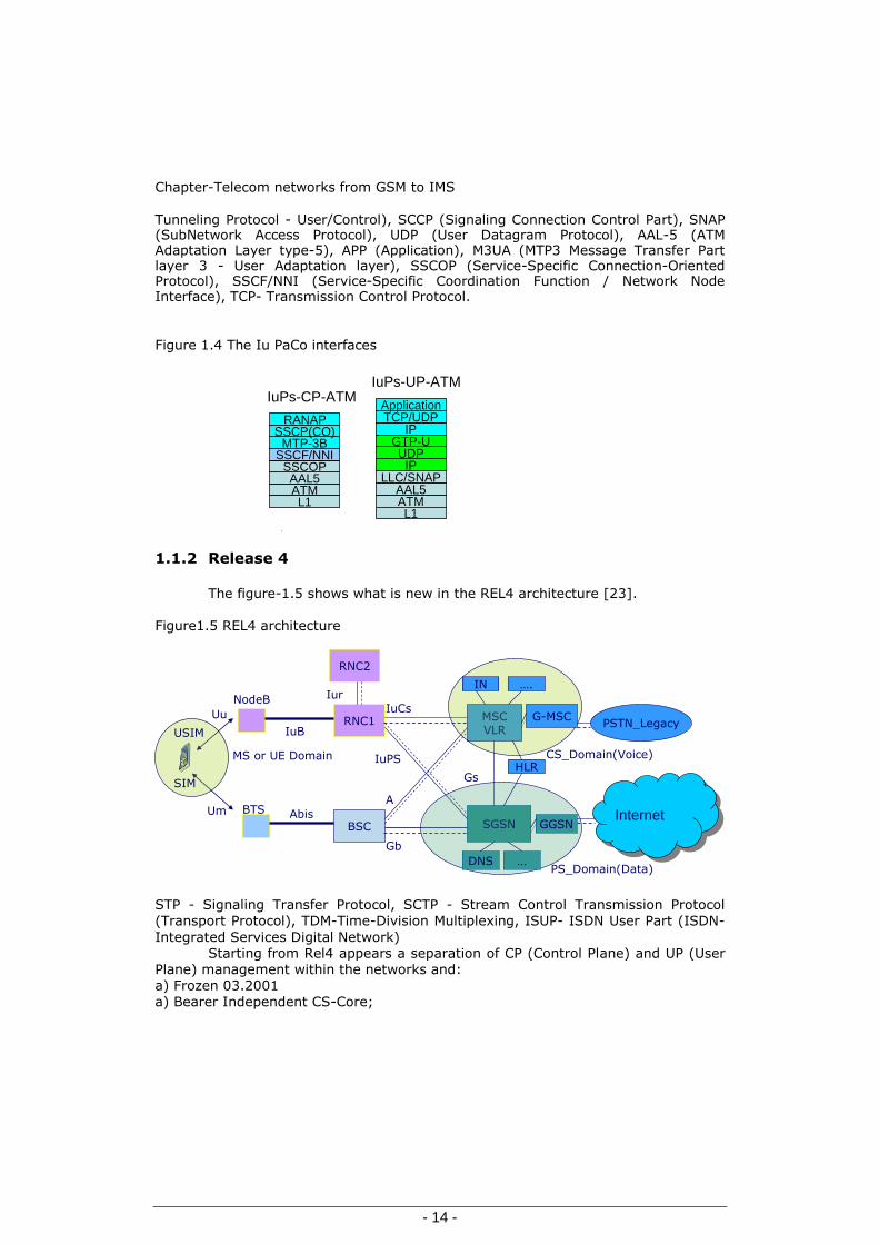
Iu–PS interface - Figure 1.4 - (Iur, Iub: AAL–5): with AAL–5, isochronous connections with VBR in a connection-oriented mode are supported. This layer is used for Internet protocol (IP) local-area network (LAN) emulation and signaling. In UTRAN, AAL–5 is used to carry the PS user traffic in the Iu–PS-interface and the signaling and control data throughout.
An ATM (Asynchronous Transfer Mode) network is composed of ATM nodes and links. The user data are organized and transmitted in each link with a stream of ATM cells. AALs (ATM Adaptation Layers) are defined to enable different types of services with corresponding traffic behavior; two of these are applied in UTRAN: Iu–CS (Iur, Iub: AAL–2) and Iu–PS (Iur, Iub: AAL–5).
Figure 1.4 shows the most important new PS-CN (Packet-Switched-Core-Network) or PaCo interface-Iu and abbreviations: PaCo (Packet Core), RANAP (Radio Access Network-Application Part), LLC (Logical Link Control), GTP–U/C (GPRS
Chapter-Telecom networks from GSM to IMS
- 14 -
Tunneling Protocol - User/Control), SCCP (Signaling Connection Control Part), SNAP (SubNetwork Access Protocol), UDP (User Datagram Protocol), AAL-5 (ATM Adaptation Layer type-5), APP (Application), M3UA (MTP3 Message Transfer Part layer 3 - User Adaptation layer), SSCOP (Service-Specific Connection-Oriented Protocol), SSCF/NNI (Service-Specific Coordination Function / Network Node Interface), TCP- Transmission Control Protocol.
Figure 1.4 The Iu PaCo interfaces
ATMAAL5
SSCOPSSCF/NNI
L1
MTP-3BSSCP(CO)
RANAP
IuPs-CP-ATM
ATMAAL5
LLC/SNAPIP
UDPGTP-U
IPTCP/UDPApplication
L1
IuPs-UP-ATM
1.1.2 Release 4
The figure-1.5 shows what is new in the REL4 architecture [23].
Figure1.5 REL4 architecture
MSCVLR
SGSN
RNC1
BSC
IuCs
A
Gb
IuPS
PSTN_Legacy
Gs
InternetInternet
PS_Domain(Data)
CS_Domain(Voice)
NodeB
IuB
AbisBTS
USIM
SIM
MS or UE Domain
Uu
Um
RNC2
Iur
HLR
IN ….
GGSN
DNS …
G-MSC
STP - Signaling Transfer Protocol, SCTP - Stream Control Transmission Protocol (Transport Protocol), TDM-Time-Division Multiplexing, ISUP- ISDN User Part (ISDN-
Integrated Services Digital Network) Starting from Rel4 appears a separation of CP (Control Plane) and UP (User
Plane) management within the networks and: a) Frozen 03.2001 a) Bearer Independent CS-Core;

Short Introduction of 3GPP Releases
- 15 -
b) GERAN A/Gb mode (EGPRS) c) CS Core Transport over IP
d) Split CP from UP: - UP over MGW (Media Gateway) and - CP over MGC (Media Gateway Controller-MSC-Server)
Enclosed a short description of the new interfaces introduced with REL4:
Mc is the interface between MGC and MGW. On Mc it uses the H.248 or
MEGACO (Media Gateway Control) protocol. MEGACO protocol was designed for the media gateways with distributed subcomponents required in complex networks. It is
specified in RFC.3015 later replaced by RFC.3525 and aligned with ITU-T specification H.248, which itself supplements the earlier H.245 gateway component of the H.323[7] videoconferencing standard [1, 2, 3]. MEGACO is used between a media gateway (MGW) and media gateway controller (MGC) to handle signaling and session management during a multimedia conference. The media gateway controller and the media gateway share a master/slave relationship.
The connection model for protocol describes the main objects within a MGWs as terminations and contexts that can be controlled by the MGC. A termination sources or sinks (either originates or terminates) one or more streams, and each termination holds information about the actual media streams. Different terminations are linked together by a context. The set of terminations that are not associated with other terminations are defined as being represented by a special
type of context (namely, the null context). A context describes the topology of
terminations associated with it: for example, it includes parameters about mixing in case the context contains more than two terminations.
With help of MGW and MEGACO in the same context could be present TDM-trunks (GSM-A or ISUP-TDM), ATM channels (IuCS) or RTP –VOIP channel. Megaco/H.248 provides the commands:
- for termination manipulation: Add, Subtract, Move, Modify - for event reporting: Notify - for management: Audit Capability, Audit Value, Service Change
Nc interface between different MGCs over STPs or without STPs, the
Network-Network based call control is performed. Classical ISUP is working on TDM
networks where we have typically CIC (Circuit Identification Code) also inside of these messages are present call control and bearer control information. BICC is an ISUP extension able to manage any type of bearer, like TDM, ATM and IP.
The protocol used on the Nc interface is specified in TS 29.205: "Application of Q.1900 Series to Bearer Independent circuit-switched core network architecture; Stage 3". In fact, the Nc interface uses ITU's BICC as specified in ITU Rec. Q.1902.x
series of recommendations of the call control entities from the bearer control entities, hence the name "Bearer-Independent Call Control" [23].
The interworking between BICC and ISUP shall follow the ITU recommendation Q.1912.1 ("ISUP-BICC Interworking") and Q.19.12.2 ("Interworking between selected signalling systems and BICC") [23].
Nb represents the UP interface between different MGW of the network. In the case of ATM or IP transport, the passage of compressed speech at variable bit
rates is possible through the CS core network

Chapter-Telecom networks from GSM to IMS
- 16 -
Main transport protocols are/was used in the most networks: - Real-Time Transport Protocol (RTP) and Real-Time Control Protocol (RTCP) - RTP dedicated for real time services like audio and video calls. - Real-Time Control Protocol (RTCP) it is able to monitor the quality of transported data.
In the most real implementation IuCS on ATM is present till MGW, and there
it is done an adaptation to IuCS on IP (on SCTP with different UA user adaptation
layers = SIGTRAN-signaling transport) in MGC direction (and the ALCAP- Access Link Control Application Part used for control plane of transport layer in ATM remain present till to this adaptation module). The same adaptation in the same way it is done for A interfaces - TDM to IP.
1.1.3 IMS-IP Multimedia Subsystem and introduction of REL5,6&7
The IMS definition started within 3GPP(The3rd Generation Partnership Project) organisation, which has as partners[50]: - ARIB Association of Radio Industries and Businesses, Japan
- ATIS (T1 comities) The Alliance for Telecommunications Industry Solutions, USA - CCSA China Communications Standards Association
- CWTS-China Wireless Telecom Standard Research team - ETSI (European Telecommunications Standards Institute) - TTA Telecommunications Technology Association, Korea - TTC Telecommunication Technology Committee, Japan.
The partners have agreed to cooperate in the production of globally applicable Technical Specifications and Technical Reports for an evolved 3rd Generation and beyond Mobile System based on evolved 3GPP core networks the radio access technologies will support (Universal Terrestrial Radio Access -UTRAN) FDD (Frequency Division Duplex) and TDD (Time Division Duplex ) modes. The partners have further agreed to cooperate in the maintenance and development of
the Global System for Mobile communication (GSM) Technical Specifications and Technical Reports including GSM evolved radio access technologies (e.g. General Packet Radio Service (GPRS) and Enhanced Data rates for GSM Evolution (EDGE)).
The partners have agreed that the further evolution of IMS should be done in an access independent manner.
3GPP is established for the preparation, approval, and maintenance of the
above mentioned Technical Specifications and Technical Reports. 3GPP is not to be created as a legal entity [25]. Starting from this initial scope under Release5 (which is also first All-IP architecture) was defined the IMS-IP multimedia subsystem and the improvement was done within Release6 and Release7 representing the normal network evolution from CS to PS network. In these releases it can see a network based on 3 separated plans (in REL4 was 2 plans CP and UP):
a) UP-Plane or IP-CAN based on PS core (the exiting for mobile was- GPRS-UMTS core) b) CP-Plane based on IMS core
c) Services Plane or Application (Application servers, OSA, Camel).

Short Introduction of 3GPP Releases
- 17 -
The network element has the ability to establish new calls; a “call” in IMS it is defined as a session. Under a session we can have a voice call and other services,
multimedia (audio plus video) stream Like call control protocols in the packet-based networks could be used: H.323 (adopted by the ITU in 1996 ) and SIP.
As IMS main protocol was chosen SIP (Session Initiated Protocol) defined by IETF for its flexible syntax and to facilitate development and interconnectivity between 3GPP networks and fixed IP networks [24]. From protocols point of view on IMS, SIP was defined like E2E network protocol. But there will be presented also
others protocols like these mentioned below:
a) IP-CAN protocols (PS core Mobile like RANAP on IP (SIGTRAN) IP, UDP, GTP-C&U, TCP, Application-layer: HTTP-Hypertext Transfer Protocol FTP-File Transfer Protocol …). b) SIP defined like SIP E2E network with:
1) SDP-Session Description Protocol one application layer protocol, text based protocol offering the information about multimedia session making offering many possibilities of media negotiation[5][6],
2) SigComp-Signaling Compression- in the access side because SIP messages are to big and to keep the latency under control and not increase the bandwidth usage could be used a compression and decompression mechanism (decompression for output from the SigComp system in the network direction)[8],
c) RTP–real time protocol for real time application (voice/video) and RTCP –RTP–CP– control protocol used to monitor of RTP quality, d) DNS – Domain Name Server offering the association between domain name and an IP address depend on the point of interrogation, e) ENUM (DNS and NAPTR – naming authority Pointer) used to convert a Phone number present in E.164 format to SIP-URI (universal resource identifier) giving also the possibility to verify or not the IMS subscription (Telephone number
mapping). f) Start from Radius-protocol – Remote Authentication Dial in User Service was implemented a better one protocol how the name say, Diameter it is a 3xA protocol: AAA (Authentication, Authorisation and Accounting) (BetterDiameter=2Radius –
like in mathematics how the name shows D=2xR in),
g) MEGACO or H.248-Media Gateway Control Protocol (also present in Release 4), k) COPS-Common Open Policy for QoS (Quality of Service) control-based on
definition on this one maybe/will replaced with Diameter from Release 6 and 7, l) For not trusted area of domains and TLS (Transport Layer Security) based, for security reason could be used IP-SEC (IP SECurity).
Based on chosen protocols IMS could meet all expectation and future
requirements regarding E2E call sessions, call setup, mobile originating and terminating call, network security and hiding its topology, charging and emergency calls and able to work also with IPv6 or double stack IPv4&6. Observing the releases evolution, starting with release 5 till to 7 the IMS definition for mobile area was done on UMTS, improving the IMS components and UMTS data rates transfers. For this reason we are presenting these main improvements from Release 5, 6 and 7 in
the same subchapter:

Chapter-Telecom networks from GSM to IMS
- 18 -
Release 5 [24] a) Frozen 06.2002 b) IP-UTRAN with others words Iub, Iur, Iu-CS and Iu-PS on IP
c) Iu-Flex- Feature introduces the ability to connect RNCs to more than one MSC and to more than one SGSN d) Introduction of RNC inter-working with Multiple Core Controllers-Network sharing.
More about Multi Operators see in Release6 (done only Stage1 of specifications) e) HSDPA- High-Speed Downlink Packet Access - up to 14 Mbps d) IMS-IP Multi-Media Subsystem-“All over IP” e) SIP Call Control protocol for the IMS
Release 6 [26] a) Frozen 03 (Q1/Q2) -2005 b) HSUPA (High Speed Uplink Packet Access)–up to 5.6 Mbps c) MBMS (IP based Mobile Broadcast Multicast Services)
d) Complementing IMS &3.5G Mobile Generation e) Mobile Phone in dual mode - GSM and Wi-Fi (Wireless Fidelity) within definition on GAN (Generic Access Network) d) PoC (Push to talk over Cellular)
e) Network Sharing (Stage2&3)
Release 7 [27] The Figure-1.6 presents details about IMS Topology and IP-CAN mobile existing under this releases [8] [11] a) Frozen 12-2007 b) 3.75G-Mobile Generation c) HSPA+ Improvements; Performance improvements to HSPDA/HSUPA d) GERAN Performance (EGPRS2)
e) Femtocell introduction f) Performance & QoS to support IMS e) PS-Handover g) MIMO (Multiple Input Multiple Output antennas)
k) 64QAM (Quadrature Amplitude Modulation) in HSDPA (HSUPA- 16 QAM) 21- 28Mbps
l) MMTEL TISPAN requirements for Multimedia Telephony with PSTN/ISDN simulation services

Short Introduction of 3GPP Releases
- 19 -
Figure-1.6 IMS-Architecture Layers
UE
S-CSCF
HSS
BGCF
MGCF
MGW
SGW
Mn
CSSignalling
Media
Mw
Mj
I-CSCF
Mw
Cx
Cx
Mi
Mg
SLF
Dx
Dx
MRFC
Mr
MRFP
MpSIP AS OSA SCS IMS SSF
ISC
ShSi
GGSNSGSN
RNC
NodeB
GPRS(IP-CAN)
Mb-Media
Mm/Mw
Mk
Rx(Gq)Gx(Go)
Mb/Gi
PCRF(PCF)
SPR
GmSIP
Mb-Media
PDP
Gm(CP)
MediaUP
OCSOFCS
GyGz
Sp
Gi-Data
CP
UP
UP-between UE & NodeB
InternetIMS-NetworksOther IMS networks
OthersCS-Netork
AS
AS
P-CSCF,AFC-BGF
Mb-Media
Mb-Media
Below is enclosed a short IMS-Architecture, description (functionality will be
explained later in few calls scenarios): UE-User Equipment
UE could play following role: UAC SIP User Agent-Client and UAS SIP User Agent-
Server Depending from the Call Session scenarios where UE is involved. UE including for authentication reason an I-SIM or minimum the old U-SIM (depend on authentication algorithm implemented)
For security reason UE has two identities: -IMPI-IP Multimedia Private Identity Saved on ISIM or USIM (could not be modified) -IMPU-IP Multimedia Public Identity (URI or a Number in format E164) UP-Plan-components or Transport Layer
IP-CAN – IP Connectivity Access Network Under IP-CAN name could be presented the following components:
- RAN - Radio Access Network

Chapter-Telecom networks from GSM to IMS
- 20 -
- SGSN - Serving GPRS Support Node - GGSN - Gateway GPRS Support Nod Call Session Control Plan/CP-Plan
P-CSCF -Proxy Call Session Control Function. I-CSCF -Interrogating Call Session Control Function S-CSCF -Serving Call Session Control Function
PCRF (PCF) -Policy and Charging Rules Function (Policy Control Function) HSS -Home Subscriber Server SPR -Subscriber Policy Register SGW -Signalling Gateway
C-BGF -Core Border Gateway Function- UP role MGCF -Media Gateway Control Function MGW -Media Gateway-UP role MRF -Media Resource Function-with two components:
MRFC -Media Resource Function Controller MRFP -Media Resource Function Processor-UP role
Service Control –Plan SIP AS -Application Server
IMS SSF -IMS Service Switching Function (Interface SIP to CAP from GSM intelligent network)
OSA SCS -Open Services Architecture Service Capability Server (Parlay Service) OCS -Online Charging System OFCS -Offline Charging System
A call session has to be established in three steps: a) UE (during Registration) is able to request the PDP (packet data protocol) context for SIP and MEDIA within CP from IP-CAN
b) Gm-SIP session will be started via GPRS tunnel to Gi in direction P-CSCF-IMS
core c) Media will be established based on Call-Session Request/SIP and bearer request will be established also with help of PCRF (Rx->Gx interfaces - QoS offered), the way is: Tunnel IP-CAN (start from air interface – represented in yellow-black- color-> continue as an application in GTP-U tunnel –ETH/IP/UDP/GTP-U/IP/UDP/RTP) till Gi
(IP/UDP/RTP…) and BGCF
In the next table, are presented the most important interfaces of IMS (Interfaces, Rel-7).

Short Introduction of 3GPP Releases
- 21 -
Table 1.1 Descriptions of Interfaces (Release 7)
Interfaces Components IMS Protocol
Gm UE - P-CSCF SIP
Mw P-CSCF-I-CSCF-S-CSCF SIP
ISC S-CSCF, I-CSCF-AS SIP
Cx I-CSCF, S-CSCF-HSS DIAMETER
Dx I-CSCF, S-CSCF,-SLF DIAMETER
Sh SIP AS, OSA SCF-HSS DIAMETER
Si IM-SSF-HSS MAP
Mm I-CSCF, S-CSCF-external IP network Not Specified
Mg MGCF - I-CSCF SIP
Mi S-CSCF - BGCF SIP
Mj BGCF - MGCF SIP
Mk BGCF - BGCF SIP
Mr S-CSCF, MRFC SIP
Mp MRFC- MRFP H.248
Mn MGCF- IM-MGW H.248
Ut UE-AS (SIP AS, OSA SCS, IM-SSF) HTTP**
Gx(Go) PCRF(PCF)-GGSN DIAMETER(COPS*)
Rx(Gq) P-CSCF-PCRF(PCF) DIAMETER
Gy GGSN-OCS DIAMETER
Gz GGSN-OFCS DIAMETER
Sp PCRF-SPR DIAMETER
*COPS (Common Open Policy Service) see RFC2748 **Ut interfaces is not represented in Figure-1.6 How can be observed in Table 1.1, the most used protocol is SIP and on the second place landed Diameter.
SIP, is specified in RFC 2543(Request for Comments) using the Client-Server mechanism.
SIP could work on UDP, TCP or SCTP depends on implementations and
needs. To assures the interconnection of the IP networks with old CS-Telecom world within SIP it was defined SIP-T&SIP-I.
There were defined few SIP functions to map in to SS7-ISUP interconnection requirements, which have to work in both direction IPCS keeping the continuity
of services. Start from the first SIP[5][6] definition of IETF (Internet Engineering Task
Force) and taking in consideration its flexibility; it was possible to adapt SIP to the IMS implementation[8].
SIP messages contain (see Figure 1.7): First-Line Request-Response we can find the destination and the operation
required

Chapter-Telecom networks from GSM to IMS
- 22 -
Headers Typically application and routing information, UAC SIP request contain minimum the following headers: To From Cseq
Call-ID Max-Forwards Via
Body SDP, XML.HTML, MMS
PDIF-Presence Information Data Format (RFC-3863) RLM-Resource List Meta Information (RFC-4662)
During of IMS specification was necessary to adapt also SIP to the new requests; see below few new components in SIP-IMS: a) SIP new request method
SUBSCRIBE PRACK
UPDATE MESSAGE (SMS) NOTIFY (Presence)
b) Specification of timer values
c) SDP –Offer/Answer adapted to the new session d) New-Headers like:
P-headers
Route Path (ex.-P-SCCF address in REGISTRATION) SIP session (see Figure 1.15) is initiated by an “INVITE” and (could) contain
proposed media offers (SDP-Offer will be negotiated). The basic rule of SIP routing was specified on RFC 3261 and is based on: a) UAC sends the request to SIP local Proxy b) SIP Proxy performs DNS query/lookups for URI requested
c) SIP proxy (in the next step) will do the routing to the home domain of UAS d) SIP proxy from home domain will perform HSS query and route the request to UAS. INVITE Request will indicate the setup path, with others words each UAC and
Proxies will add to VIA-Headers own address. The responses like 200-OK use and carry these VIA looking on the top will come back on same path as the INVITE. This
routing method will guarantee that the responses are routed to the same proxies as requested. In IMS the Proxies which wishes to remain in the dialog after establishment phase (this allow the P-CSCF /S-CSCF to influence on demand the session) has to add own URI-address to the Record-Route-Headers (with multiple Branch-Forking) in the Request Method –INVITE.
Observations about SIP-headers: INVITE/REINVITE/UPDATE/OK/ACK/MESSAGES have to pass always through. Proxy-Servers have been already added VIA-Headers. Based on the Contact Headers (end-users) Subsequent Messages could be
exchanged directly between the end-users.

Short Introduction of 3GPP Releases
- 23 -
The Media will follow a dedicated User Plane path- see Figure 1.15
Very important for each operator is also the charging process; charging is to correlate bearer used within the session. This will be transmitted also with the help of SIP, where could be included (Charging Headers): P-Charging-Vector and P-Charging-Function-Address
Figure1.7 SIP message structure
The second important protocol used in IMS interfaces is Diameter. In order of importance, we have to mention also the Megaco-H248 Protocol;
its extended versions are used on many IMS references also. But an overview on it we have already in subchapter 1.1.4 Release 4.
Bellow we will continue to provide information about Diameter and it structure.
The Diameter is able to provide an Authentication, Authorization and
Accounting (AAA). For this reason it has to be more reliable; like transport protocol will be used SCTP or TCP.
Diameter messages structure are presented in Figure 1.8. AVP (Attribute Value Pairs), an optional parameter in the header the
Vendor–ID, gives a big flexibility on defining of a new functionality. For this reason
appears Diameter in many interfaces and it is able to replace other protocols
IP UDP/TCP/SCTP 1st Linie Headers Body(optional e2e)
SIP
Request Request Method Request URI SIP Version
Specified in RFC 3261REGISTER,INVITEACKOPTIONSCANCEL,BYE,From ownSpecificationsUPDATEMESSAGE(SMS),SUBSCRIBE, NOTIFY ( Presence ),PUBLISH,INFO,PRACK,REFER,
Response SIPversion Status code
Provisional Response1xxProvisional Response100 Trying180 Ringing183 Session ProgressFINAL Response 2xx Success3xx Redirection4xx Request Failure5xx Server Failure6xx Global Failure
Name:Value
Body(e2e mechanism)SDP Session DescriptionProtocolXML Extensible MarkupLanguageMIME MultipurposeInternet Mail Extentions
Headers(proxies read)Adresses for routingTransactions&DialogsUA capabilityOther infos like:Privacy settingsSecurity
E
m
p
t
y
l
i
n
e

Chapter-Telecom networks from GSM to IMS
- 24 -
providing the requested functionality (see COPS from Release5 replaced later with Diameter). From security point of view it could be used under TLS (Transport Layer Security) and IPSec (IP SECurity) having from the beginning few important mechanisms implemented like:
Loop Detection Failover-Failback Procedure Duplicate Detection
Figure 1.8 Diameter messages structure
H2H = hop by hop ID and Opt= Optional
1.1.4 IMS-IP Multimedia Subsystem, LTE, REL8, REL9, REL10 and
REL11
LTE (Long Term Evolution) was introduced within Release 8.
But how we could observe, LTE occupies a central place also to the others new
releases.
For this reason in our study, these new releases (8 to 11) are presented in
the same subchapter, investigating in the same time, how will look there the IMS
solution (using also the LTE new component).
The main contributions of the Releases 8,9,10 and 11 will presented below
in a short list.
Release 8 [28]
a) Frozen Q4-2008 b) First LTE-LTE/SAE- Long Term Evolution and System Architecture Evolution c) EPC-Common IMS- Evolved Packet Core e) Dual-Cell HSDPA f) OFDM- Orthogonal frequency-division multiplexing g) Very low latency (Call setup, HO …)
h) Support of variable bandwidth -1.4, 3, 5, 10, 15 and 20 MHz
Diameter Header AVP AVP AVP
AVP Header AVP Data
Diameter Header Content = Version, Length, Flags, Code, AppId, H2H Id, E2E Id0&
AVP Header Content =Code, Flag, Length, Vendor-Id (Opt)

Short Introduction of 3GPP Releases
- 25 -
k) ICS-New concept from Release 8-IMS Centralized Services l) SRVCC- Single Radio Voice Call Continuity
m) Only the single active session is transferred[12] n) SMS Short Message Service (SMS) over IP o) IMS Media support for AMR CODECs. p) Multimedia Telephony (MMTel) q) Data transfer
HSPA 42 Mbps 64QAM, 2x2 MIMO or Dual cell (10 MHz BW)
LTE 300 Mbps 64QAM, 4x4 MIMO, 20MHz BW
Release 9 [29]
a)Frozen Q4-2009
b) LTE interoperability with UMTS
c) Small LTE-LTE/SAE- enhancements - HeNB (Home eNode B, Mobility and Access) d) Dual-Cell HSUPA
e) Dual-Cell with MIMO
f) SON (Self-Organizing Networks) g) LTE-MBMS - Multimedia Broadcast Multicast Service
h) LCS Location Services-start from UP in Rel8 to CP in this one k) Data transfer
HSPA 84 Mbps, 2x2 MIMO or Dual cell (10 MHz BW)
LTE 300 Mbps 64QAM, 4x4 MIMO, 20MHz BW
l) Enhanced MSC server (conference and mid-call session will be transferring) [12] m)Emergency Call can be transferred[12] Release 10 [30]
a) Frozen Q1-2011
b) LTE Advanced
c) IMT-Advanced-4G- IMS Multimedia Telephony d) Improvement of LTE Release 8&9 to meet IMT-Advanced requirements e) SRVCC domain transfer optimisations due the presence of, AT-CF/GW access transfer control function and gateway with anchoring of the session within serving network[12][13]
f)Access Domain transfer during alerting phase[12]
g) Carriers Aggregation to improve the Bandwidth k) MIMO improvement – advanced l) CoMP - Coordination of Multi-Point Tx and Rx m) Data transfer:
HSPA 168 Mbps 2x2 MIMO, 4 carriers (20 MHz BW)
LTE 3 Gbps 64QAM, 8x8 MIMO, 100MHz BW
Release 11 [31]
It is open from begin of Q2 2011 and maybe will be published in Q3-Q4 2012. a) Data transfer expected:
LTE 3 Gbps 64QAM, 8x8 MIMO, 100MHz BW
336 Mbps 2x2 MIMO, 8 carriers (40 MHz BW)

Chapter-Telecom networks from GSM to IMS
- 26 -
b) Support of Handover from 2G/3G-CS to 4G (reverse) [12] c) Video Calls Handover [12] Start from Rel-8, LTE is occupies an important place within new releases. In 3GPP TS 23.401(and helpful for architecture are also 3GPP- TS 23.402&TS36.300) was defined the EPS (Evolved Packet System) - see Figure 1.9 -
and the components: 1) e-NodeB- E-UTRAN for LTE Access
and
2) EPC-Evolved Packet Core
Figure 1.9 Evolved Packet Systems and few ICS-IMS Centralized interfaces
MME
S1-CP
HSS
SGi
P-CSCF
S6a
S3
S10
PCRF
Gx Rx
CP
UP/SGi
S-GW
MME
P-GWPDN
x2
S5/S8S1-U
S11
SGi
SPR
OCS-OFCS
Gy Gz
AAA
SGi
DNS
IMS
Internet
eNodeB
eNodeB
SGSN
UTRANGERAN
S12
SP
S4
MGW
MSS(C)MGC
PS-2&3G
Sv
UTRAN
GERAN MGWIMSMGC
I2
RTP
CS-2&3G
UE
Below few details related to the above figure(Figure 1.9):
AAA (on the same Layer1 as SGi) Radius or Diameter DNS the same as in 2&3G-PS network ( see S11/Gn SGi/Gi) OCS-OFCS the functionality will be present in core IMS also In many real implementation S-GW&P-GW will be together in the same colocated-HW presented like UGW-Unified Gateway I2, interface between CS-MSC(MGC) enhanced for ICS/SRVCC and the IMS core, is
used in an SRVCC context PS 2g&3G could be used like IP-CAN also see Figure-1.6
In Table 1.2 will be completed short information about these interfaces and protocols, using Figure 1.9 as reference.
The Sv interfaces messages contents, were defined in 3GPP TS 29.274 [32].
Sv interface is positioned between the MME/SGSN and MGC-MSC Server from CS
(2G-3G) network, having a very important role in implementing of SRVCC (Single

Short Introduction of 3GPP Releases
- 27 -
Radio Voice Call Continuity) as defined in 3GPP TS 23.216 [33]. On Sv physical layer could remain in use SGs/Gs also - between MME/SGSN – MGC MSC Server, for CSFB
–circuits switch fallback, useful - for customers without IMS subscription (for example-inbound roaming).
I2 has a very important roll in ICS-IMS Centralized services (with modification of MSC - Server – IMS -MGC or these both could be implemented in the same HW).
S13 interfaces is not represented in Figure 1.9, being the interface between
MME and EIR (Equipment Identity Register) used to obtain the IMEI (International
Mobile Station Equipment Identity) in use in the network, building a wide, grey and black list. This functionality was specified also in the past (GSM) but in real networks didn’t exist many operators which used it with the original purpose. Many operators use this one functionality for other applications, doing a network quality analyse in direct connection with IMEI and having in this way useful information about mobiles which create the most of issues, divided per services, profiles and groups of customers also; having later also the possibility to adapt, on demand the mobiles
configuration to real network services and users needs.
Table 1.2 Interfaces and protocols EPS
Interfaces Components LTE Protocol
x2 eNodeB - eNodeB x2-AP
S1-CP eNodeB-MME S1-AP
S1-UP eNodeB - S-GW GTP-U
S3 SGSN-MME GTP-Cv2
S4 SGSN-S-GW GTP-Cv2 and GTP-U *
S5 S-GW - P-GW GTP-Cv2 and GTP-U **
S6a MME -HSS DIAMETER
S8 S-GW - P-GW GTP-Cv2 and GTP-U **
S9 PCRFHome - PCRFVisited DIAMETER***
S10 MME -MME GTP-Cv2
S11 MME - S-GW GTP-Cv2
S12 UTRAN-S-GW GTP-U ****
SGi P-GW- IMS/Internet ***** See below
Gx PCRF- P-GW DIAMETER
Rx P-CSCF-PCRF DIAMETER
Gy P-GW - OCS DIAMETER
Gz P-GW - OFCS DIAMETER
Sp PCRF - SPR DIAMETER
Sv MSC-Server – MME(SGSN) GTP-Cv2
I2 MSC-Server – IMS-MGC SIP
*S4: GTP-Cv2 providing the mobility control between GPRS Core and S-GW, and if Direct- Tunnel is not in used in 2G or 3G PS network, on this one will be sends UP-GTP-U. **S5/S8 could be implemented using PMIP (Proxy mobile IP) protocol, this one implementation is described in TS 23.402. ** S5 provide CP an UP management between S-GW and P-GW, very important application for the S-GW and P-GW functionality collocated in the same HW; in this case and in the case S-GW

Chapter-Telecom networks from GSM to IMS
- 28 -
relocation during of UE mobility process and if P-GW in use will be one not collocated with the S-GW. **S8 – in the case of rooming, like CP and UP management between visited S-GW and home P-GW. **S5 and S8 have the same functionality with the following specification: S8 is the S5 interface but for inter PLMN case (These can be
comparing with Gn and Gp in the case of GPRS). ***S9 not represented in Figure 1.9. ****S12 UP (GTP-U) in the case of Direct Tunnel, the most operators has it already implemented in the case of UTRAN (GPRS). *****SGi as protocol stack is on
L1/L2 (ETH-Ethernet) IP/UDP or TCP /Applications, for this reason could be uses like:
a) Gm - interface between P-GW and P-CSCF having SIP on the TOP (L1/L2
(ETH-Ethernet/IP/UDP or TCP /SIP like Application)
b) SGi It is the interface between the PDN GW and the Internet
c) SGi is the interface between the PDN GW and other IMS for transport of
Media (L1/ETH/IP/UDP/RTP)
See below the Figure 1.10 and Table 1.3, there we are trying to offer an overview of LTE topology under IMS and few information about interfaces and
protocols in use. LTE offer new possibilities and new reasons for IMS implementation. The abbreviations used in Figure 1.10 are:
AF Application Function AS Application Server BGCF Border Gateway Control Function DNS Domain Name System
ENUM E.164 Number Mapping HSS Home Subscriber Server I-CSCF Interrogating Call Session Control Function ISC IMS Service Control MGC Media Gateway Control Function MGW Media Gateway MRFC Media Resource Function Controller
MRFP Media Resource Function Processor PCEF Policy and Charging Enforcement Function PCRF Policy and Charging Rules Function
P-CSCF Proxy Call Session Control Function PDN Packet Data Network P-GW PDN Gateway
SGW Signaling Gateway S-GW Serving Gateway S-CSCF Serving Call Session Control Function SPR Subscription Profile Repository UDR User Data Repository UE User Equipment To complete the build of future implementation -“All-IP”, LTE architecture
utilisations under IMS as IP-CAN and few details about IMS topology-components
will be represented within next figure- Figure 1.10

Short Introduction of 3GPP Releases
- 29 -
Figure 1.10 Evolved Packet System and IMS
P-CSCF AF,C-BGF
S-CSCF
HSS
BGCF
MGCF
MGW
SGW
Mn
CSSignalling
Media
Mw
Mj
I-CSCF
Mw
Cx
Cx
Mi
Mg
SLF
Dx
Dx
MRFC
MrMRFP
Mp
SIP ASISC
Sh
PGW
MME
E-NodeB
SGi-Mb
Mm/Mw
Mk
RxGx
PCRF
SPR /UDR
SGi-SIP
Gm
Sp/Ud
SGi-Data
CP
UP
Internet
IMS-networksOther IMS networks
OthersCS-Netork
DNS /ENUM
S-GW
S1-MME
S5
S6a
S11
S1-U
Default Bearer-2
Dedicated
Bearer
Default Bearer-1
Gm&IMS-Media
Internet
UEs Ut
UE-AS Service Management
Sh
Mb
Mb
Mb
In the future, the interconnection to the other CS Networks will be possible
and done as today-see Figure 1.10 Others CS Networks are as today: PLMN -Public Land Mobile Network
PSTN -Public Switched Telephone Network Based on 3GPP TS 23.335 and 3GPP TS 23.203 specifications, the UDR (see
Figure 1.10 ) could replace SPR components and the Ud reference point provides
access to the subscription data in the UDR. The Ud interface as defined in 3GPP TS 29.335 is the interface between the PCRF and the UDR [34].
In already mentioned Figure 1.10, there are showed also the most
important interfaces of “All-IP” mobile implementations (using only 4G). The knowledge about the interfaces specifications and their format, are
decisive for network elements and network managements solutions.And we could mention that, for our study, for good Tracing System implementations, the central point to start any activity it is; to understand the network architecture and functionality based on deeper study of interfaces and protocols specifications (which will build later the call flow)
Any details and any vendor specific chances, on network interfaces and protocols, has to be take in consideration in this kind of activity.
Like start model of collecting these information about, interfaces-protocols
(LTE&IMS) and their main specifications could be used - the Table 1.3

Chapter-Telecom networks from GSM to IMS
- 30 -
Table 1.3 Interfaces and protocols LTE&IMS
Interfaces
Networks -Elements Protocols Specifications
3GPP TS IETF RFC
Cx,Dx CSCF HSS,SLF Diameter 29.228,29.229
Gm UE P-CSCF SIP 3261
Gx PCEF PCRF Diameter 29.212, 3.203
ISC S-CSCF AS SIP 23.228 3455;3
325
Mg MGCF CSCF SIP 3261
Mi CSCF BGCF SIP 3261
Mj BGCF MGCF SIP 3261
Mn MGCF MGW Megaco 3525
Mp MRFC MRFP Megaco 3525
Mr S-CSCF MRFC SIP 3261
Mw P-CSCF I-CSCF,S-CSCF SIP 3261
Rx AF PCRF Diameter 23.203,29.214
S1AP E-NodeB MME S1-AP&NAS 36.410
S1-U E-NodeB S-GW GTP-U 36.401, 36.410
S5 S-GW P-GW GTP-Cv2-
>CP, GTP-U->UP
29.274->CP; 29.281->UP
S6a MME HSS Diameter 29.272
S11 MME S-GW GTP-Cv2 29.274
S10 MME MME GTP-Cv2 29.274
Sh HSS AS (could be for
SPR&UDRalso) Diameter
29.328,
29.329
Sp SPR PCRF Diameter 29.203, 29.328,
29.329
Ud UDR PCRF Diameter 29.203,
29.328, 29.329
Ut UE AS HTTP 2616
Mb RTP-based
Bearer RTP 29.162,
TR 23.899 4867
SGi P-GW PDN-IMS,Internet,MGW
Appication on:
SCTP,TCP or
UDP
29.061
IC* Sig-
GW,MGW PSTN,PLM TDM(SS7…) 23.002
IC*- interconnect CP- & UP
Anyway the work has to continue, collecting also the vendor specifications and so
on.

Short Introduction of 3GPP Releases
- 31 -
1.1.5 The Unified Multi Services Network – ICS “IMS centralized
Services”
The main target of IMS is to unify all existing networks and services using ICS (IMS -Centralized Services) concept (Figure 1.10). We have a centralized IMS application for all Telephony calls that means the same services in all domains. Based on this implementation Cs-Core Telephony remains in the picture for a long
time helping for a good transitivity and also will help for cases of inbound and
outbound rooming, for different roadmap of IMS, a different countries and International-Roaming partners. ICS has applicability for: a) Different Core Technologies: CS-Core-GSM, UMTS, CDMA2000-1x, PSTN and PS-Core (LTE, GPRS, DSL); b) Different Access Technologies: 3GPP Cellular, WiFi (a trademark of the Wi-Fi Alliance), Wire line & Offer many advantages like: ICS reuses the existing Telephony infrastructure; it simplified the CS-PS convergence which
becomes a seamless CS- handover; Call Routing is done in IMS (see Figure 1.11); the Cs-Domain MSC role reduces to Inter-MSC Mobility within the 2G/3G Handover.
Figure 1.10 IMS centralized Services
IMS-Core
Application-Server forPresence,Messaging,
PoC&
SCC-AS*IMS finds the other
terminal and connectsthe terminals with IP
Find and connect
Packet switchednetwork
Any IP connectionCDMA,GPRS,EDGE,WCDMA,WLAN,ADSL,
or LTE
SIP SIP
User plane connection
CS-Switch(MSC-S)
MGWCSDomain
Mobile & Fix CSGSM-UMTS
PSTN
* SCC AS-Service Centralization & Continuity Application

Chapter-Telecom networks from GSM to IMS
- 32 -
Figure 1.11 Call Routing
MSC-S
MGWCS-Domain
S-CSCF
SCCAnchor
IMS
User plane connection
PS-Domain
SIP
The session call’ signaling is routed trough IMS and Media-User-Plane will be routed on its dedicated way (start from MGW till Gi/SGi interfaces from GGSN/PGW in the case CS-PS/LTE). Based on IMS anchored model, any call generated by this user will have to be handled within the IMS world and for example; when a user
turns on his mobile, he is registered to IMS (and CS if is the case) and also the user is an IMS subscriber with a user profile in IMS. Let summaries what is realized with help of ICS:
a) Services Convergence b) Centralized Service Platform c) Offer a unified network management, operates and changes of the same services
over a range of different access technologies. d) Device Convergence -``Multi Mode Device`` supporting multiple access technologies (fixed / cellular / Wi-Fi) e) Multi Handover Hierarchy Network (between different access technologies) with Seamless Handover Homogenous Handover
(Within 3GPP access based on GTP-GPRS Tunnelling Protocol e.g
GPRS-E-Utran) Intra RAT HO within the same Radio access Technology Inter RAT HO between 3GPP Family technologies (e.g E-UTRAN to
GERAN) Heterogeneous Handover
Heterogeneous Handover -non 3GPP-based on MIP -Mobile Internet
Protocol Heterogeneous HO between 3GPP technologies e.g LTE to Wi-Fi
f) FMC-Fixed Mobile Convergence –very important for the future implementation (3GPP and non 3GPP- Seamless Service Continuity over different access networks (Fixed, Cellular, Wi-Fi) g) Seamless escalation between Voice, Video and Text communication. Enable users to roam from CS to IP networks with no interruption of service. e.g., user in WLAN
moves to 3G or vice versa, Call Continuity Control Function mediates between CS and IMS
To have and overview and to see the complexity of the future telecom implementation under IMS, below on the Figure 1.12 represented the topologies on
the case of Mobile Networks (2G/3G/4G under IMS).

Short Introduction of 3GPP Releases
- 33 -
In 3GPP TS 29.334 V10.2.0 (2011-09) it is better presented the interconnection of old CS-mobile networks to IMS using ICS concept based on:
ATCF - Access Transfer Control Function with help of I2 interfaces to MGCF (MSC )modified) CS-Control Plane
ATGW-Access Transfer Gateway using Mb interfaces to MGW- Cs Media-User Plane Between ATCF and ATGW will work a new Iq interfaces based on H248
extended version These both have a role on SRVCC domain transfer optimisations;
due the presence of, AT-CF/GW access transfer control function and gateway-with
anchoring of the session within serving network [12] An example of a Handover using the same (above) specification it is presented on Figure 1.16 Figure 1.12 IMS centralized Services-Topology-Details
S-CSCF
HSS
BGCF
MGCF
MGW
SGW
Mn
CSSignalling
Media
Mw/Mx
Mj
I-CSCF
Mw
Cx
Cx
Mi
Mg
SLF
Dx
Dx
MRFC
Mr
MRFP
Mp
ISC
Sh
PGW
MME
E-NodeB
Mb/Media
Mm/Mw
Mk
RxGx
PCRF
SPR/UDR
GmSIP
Gm
Sp/Ud
SGi-Data
CP
UP
Internet
IMS networksOtherIMSnetworks
OthersCS-Netork
DNS/ENUM
S-GW
S1-CP
S5
S6a
S11
S1-U
Default Bearer2
Dedicated
Bearer
DefaultBearer1
Gm&IMS-Media
Internet
UEsUt
UE-AS Service Management
Sh
MGW
eMSS(C)MGC
Sv
UTRAN
GERAN
I2
Media-Mb
LTEDATA&VOICE
ATCF
ATGW
SvSv
SGSN
UTRANGERAN
S12PS-2&3GDATA
UE
S4S3
CS-2&3G VOICE
IMS
Mb
Iq
SCC-ASMMtel-AS
Mw/Mx
SGiMedia/Mb
Mb/Media
P-CSCF,AFC-BGF
IBCF
IBGF
In many real networks the P-CSCF, AF, C-BGF, ATCF, ATGW functionalities
will be included on SBC (Session Border Controller)-depending on the vendors IMS implementations. This will simplify the topology and few interfaces in reality will be not anymore presenting (i.e. Iq)
MS

Chapter-Telecom networks from GSM to IMS
- 34 -
In our diagram from Figure 1.12, the functionality related to IPs network interconnects: I-BCF (Interconnection Border Control Function) &I-BGF (Interconnection Border Gateway Function) are not fully represented. Also these both functionalities could be in many real networks integrated in the SBC
1.1.6 IMS Calls-Flow examples
How it was mentioned, to be able to develop and to implement a tracing system concept for a dedicated network the work has to include study of:
Network architecture and topology
Network and Services functionality Protocols and Interfaces –standard and vendor specification and in the last but not the least Network Call Flow understanding, discovering and design it-on demand
Until now we have figure out all other steps and we will continue with few examples of call flows:
1 -LTE Initial Attach 2 - Registration –IMS-Initial Registration 3 - One example of IMS Session 4 - SRVCC from 4G to 2G without DTM support
EXAMPLE.1 - LTE Initial Attach
Based on 3GPP TS 23.401 V9.5.0 (2010-06) and few real LTE traces In our Call Flow we are in the case of UE initial attach, which is start from UE deregistered status. In the Figure 1.12 we didn’t represented all details (ex. Radio Resources Control request/response, PCRF exchange to PDN/AF/SPR). Within Attach procedure of EPS (Evolved Packet System) we can see working:
EMM-EPS mobile management and ECS-EPS connection management Below mentioned again the operations from Figure 1.13, with few details and specifying also the main new UE and Network identifiers (presented during these requests or responses):
1 ->Attach Request
IMSI International Mobile Subscriber Identity GUTI Global Unique Temporary Identity (old one will be here if is
presented in the UE-ISIM/USIM)
GUTI GUMMEI+M-TMSI-Temporary ID of UE within MME-not present at this moment
GUMMEI Global Unique MME Identity GUMMEI PLMN-ID+MMEI (MME-ID)
PLM-ID MCC Mobile Country Code + MNC-Mobile Network Code MMEI MMEGI-MME Group ID (Pool) + MMEC-MME Code S-TMSI Shorted GUTI/S-TMSI=MMEC+M-TMSI not present at this moment
TAI Tracking Area Identity=MCC+MNC+TAC tracking area code

Short Introduction of 3GPP Releases
- 35 -
ECGI Evolved Cell Global Identity-the old one is here if is presented in UE-ISIM/USIM
C-RNTI Cell Radio Network Temporary Identity Details about EPS (Evolved Packet System) identifier are presented in 3GPP 24.301 2 ->Auth_Request 3 ->Auth_Response Within this step will be done the download to MME of RAND, AUTN, KSIASME,
eKSINAS security context: EPS NAS security context - realized with help of eKSi-
evolved Key Set Identifier 4 ->Auth_Request Within this step will be done the download to UE of RAND, AUTN,eKSIASME 5 ->Auth_Response 6 ->NAS Security/Ciphered Mode Realized base on eKSINAS 7-8 ->IdentifyRequest/Response
IMEI (International Mobile Equipment Identity) will be requested and the value will be delivered on the response. 9 ->UpdateLocation IMEI will be send to HSS which can use its EIR (Equipments Identity Register) functionality 10 ->ISD (Insert Subscribers Data)
Within this step will be done the download of subscriber profile and the numbers of ISD’s operations depends on how big the profile is. 11 ->ISD-ACK 12 -> Update Location ACK(Acknowledge) 13-14 ->DNS-Request, Response: use APNs(AccesPointName) to select S-PDN-GW 15 ->CreateDefaultBearerReq.Default-APNs see Figure 1.12
IMSI,RAT(Radio Access Type), Def.BearesQoS (Defaults Bearers Quality of Services) 16 ->Create DefautBearerReq IMSI,MSISN,Def -APNs ,IP/TEIDs of SGW-S5 for GTP-Cv2 and GTP-U(TEID-Tunnel IDs) 17-18 ->Radius_req, res-Authorization

Chapter-Telecom networks from GSM to IMS
- 36 -
Figure 1.13 LTE Attach
1.Attach Request
PCRF
eNodeB
29.Update
Bearer Resp
5.NAS Security ModeComm
.
28.Update
Bearer Req
25.EPS Radio
Bearer Setup.Req&
Attach Accept
9.Update Location
15.Create.DefaultBearerR
eq
24.Attach Accept&
Initial Context Setup
Req
27.Attach Complete
HS
S
UE
2.Auth_Request
3.Auth_Response
4.Auth_Req
5.Auth_Res
eKSINAS-Sec-Context
6.NAS Security Mode Complete
eKSI
NAS
Sec
Conte
xt
10.ISD-Insert Subcribers Data11.ISD-ACK
12.Update Location Ack
DNS13-14.DNS-Req,ResUse
APNs to select S-PDNGW
16.Create.DefautBearerReqAAA
17-18.
Radius_req,res
19-20.Gx
PCRF -
Diameter22.Create.
Default
Bearer-Res
23.Create.
DefaultBearer-
Res
DNS
30-31.
DNSReq,Res
IP-Servers
from
Internet-Data
or IMS-P-
CSCF
PDN - GW
S-GW
MME
7-8.Identidy
Request/
Response-IMEI
In the most of real implementations
S-GW&PDN-GW are in the same
Hardware
IMSP-CSCF
32-33.SIP on SGi-Gm
32-33.SIP on
S5 GTP-U
Tunnel
32-33.SIP on S1U-GTP-U Tunnel
32-33. SIP on Radio
Bearer on UP
21
Query-
Sp
26.EPS Radio
BearerSetup.Res&At
tach Accept
SPR
19-20 ->Gx PCRF
Diameter actions based on AF/P-CSCF and SPR interactions see also information
about in 3GPP TS 23.203 (V9.9.0-2011-06)
21 ->SP: Here it will be delivered info to PCRF subscriber specific
iformation
22 -> Create DefaultBearerResponse
UE-Ip adress ,IP/TEID of PDN-GW,UP&CP EPS Bear-ID and QoS relate to PCRF
Could be also the P-CSCF addresses delivered or the DNS addressees
23 ->Create. DefaultBearerResponse
IP/TEIDs of S-GW-S1U info, UE IP address, IP/TEIDs of SGW-S1U
25 ->EPS RadioBearerSetupRequest Includes Attach Accept
26 -> EPS RadioBearerSetupResponse&Attach Accept
27 -> Attach Complete
EPS Bearer ID,IP/TEIDs of eNB for S1U
Short Introduction of 3GPP Releases
- 37 -
28 ->UpdateBearerRequest
S-GW-IP/TEID of eNB for S1U
29 ->UpdateBearerResponse
30-31 -> DNSRequest, Response (depend on the implementations of P-CSCF IP
discovery)
IP-Servers from Internet-Data or IMS-P-CSCF
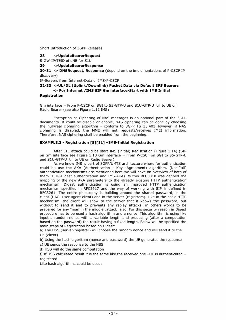
32-33 ->UL/DL (Uplink/Downlink) Packet Data via Default EPS Bearers
-> For Internet /IMS SIP Gm interface-Start with IMS Initial
Registration
Gm interface = From P-CSCF on SGI to S5-GTP-U and S1U-GTP-U till to UE on Radio Bearer (see also Figure 1.12 IMS)
Encryption or Ciphering of NAS messages is an optional part of the 3GPP
documents. It could be disable or enable, NAS ciphering can be done by choosing the null/real ciphering algorithm - conform to 3GPP TS 33.401.However, if NAS ciphering is disabled, the MME will not requests/receives IMEI information. Therefore, NAS ciphering shall be enabled from the beginning.
EXAMPLE.2 - Registration [8][11] –IMS-Initial Registration
After LTE attach could be start IMS (initial) Registration (Figure 1.14) (SIP on Gm interface see Figure 1.13 Gm interface = From P-CSCF on SGI to S5-GTP-U and S1U-GTP-U till to UE on Radio Bearer).
As we know IMS is part of 3GPP/UMTS architecture where for authentication
could be use the AKA (Authentication - Key -Agreement) algorithm. (Not “all” authentication mechanisms are mentioned here-we will have an overview of both of them HTTP-Digest authentication and IMS-AKA). Within RFC3310 was defined the mapping of the new AKA parameters to the already existing HTTP authentication mechanism. Digest authentication is using an improved HTTP authentication mechanism specified in RFC2617 and the way of working with SIP is defined in RFC3261. The entire philosophy is building around the shared password, in the
client (UAC -user agent client) and in the server (registrars). Like in the basic HTTP mechanism, the client will show to the server that it knows the password, but
without to send it and to prevents any replay attacks; in others words to be prepared for any “man in the middle „attack also. For this security reason in Digest procedure has to be used a hash algorithm and a nonce. This algorithm is using like input a random-nonce with a variable length and producing (after a computation based on the password) the result having a fixed length. Below will be specified the
main steps of Registration based on Digest: a) The HSS (server-registrar) will choose the random nonce and will send it to the
UE (client)
b) Using the hash algorithm (nonce and password) the UE generates the response
c) UE sends the response to the HSS
d) HSS will do the same computation
f) If HSS calculated result it is the same like the received one –UE is authenticated –
registered
Like hash algorithms could be used:

Chapter-Telecom networks from GSM to IMS
- 38 -
a) MD5 – specified within RFC 1321
b) SHA1 – specified within RFC 3174
c) SHA2&SHA3 – SHA3 under developing
On 02 January 2009(internet news) was announced that Security team
successfully cracks SSL using 200 Sony PS3's and MD5 flaw: They made their work
public at the 25th Chaos Communication Congress in Berlin ... The team was able to
create a rogue certificate authority and use it to issue valid SSL certificates for any
site they want. The user would have no indication that their HTTPS connection was
being monitored /modified. Looking like the 128 bit MD5 mechanism has it
weakness for this reason more secure is to use SHA-1 or SHA2:
SHA-1 at 160 bits is a little more secure SHA-2 that can produce hash sizes of up to 512 bits. SHA-3 is currently in development and promises larger hash sizes and no flaws in the algorithm.
In this direction for IMS-AKA (3GPP-AKA) was created the new algorithm
AKAvn-MD5 (n=1, 2…). The security aspects of IMS-AKA are described in 3GPP TS
33.203 (using ISIM).The initial registration consists from two parts:
a) First one from 1 to 10
b) Second from 11 to 22 First-Part 1 -> REGISTER
Home Registrar / IMPU&IMPI (Public&Private-ID) / UE-IP 1´ ->DNS_Query DNS SRV lookup according to RFC 2782. Based on the user's URI, P-CSCF determines that UE is registering from a visiting domain and performs the DNS queries to locate the I-CSCF in the home network.
1´´ -> DNS_answer Query-response also contains the IP address of the selected I-CSCF; this answer
field is used to select the I-CSCF. 2. REGISTER Home Registrar/IMPU&IMPI(Public&Private-ID)/UE-IP 3 ->UAR(UserAuthenticationRequest)
Based on user ID’s will be requested the HSS 4 ->UAA(UserAuthenticationAnsewr) HSS-IP its delivered 3´ -> UAR Request of S-CSCF- S-CSCF functionality is requested 4´ ->UAA S-CSCF functionality is requested
5 ->REGISTER S-CSCF/ IMPU&IMPI (Public & Private-ID)/UE-IP

Short Introduction of 3GPP Releases
- 39 -
6 ->MAR(MultimediaAuthenticationRequest)
S-CSCF/ IMPU&IMPI(Public & Private-ID)/UE-IP 7 -> MAA(MultimediaAuthenticationAnswer) Auth-NOK (no nonce & no response) nonce it is provided 8.9.10 ->UNAUTHORISED-401 nonce it is provided to UE
Second-Part 11.12. REGISTER -Request Home Registrar/IMPU&IMPI (Public&Private-ID)/UE-Ip / nonce & responce 13. UAR Based on user ID’s will be requested the HSS 14. UAA HSS-IP
13´ ->UAR Request of S-CSCF 14´ ->UAA S-CSCF 15 ->REGISTER S-CSCF/ IMPU&IMPI (Public&Private-ID) / UE-Ip/ nonce&response
IP of P-CSCF it is saved as Path on S-CSCF S-CSCF/ IMPU&IMPI (Public&Private-ID) / nonce&responce 17 ->MAA Auth-OK, nextnonce 18 ->SAR (Server-Assignment-Request) PUT_S-CSCF, PULL User-Profile and next nonce
19 ->SAA (Server-Assignment-Answer) 20 ->OK ( Add next nonce for UE and add the S-CSCF –IP or Service-Route to P-CSCF In the case of IMS_AKA we can see few changes: 6. MAR ->IMPI=User Name
7. MAA ->RAND, AUTN, XRES, IK, CK (AUTN-used for auth)
8.9.10. UNAUTHORISED-401 ->Send RAND, AUTN, IK, CK to UE (XRES remain in S-CSCF) 11.12. REGISTER ->Send RES 17. MAA ->Auth-OK, RES and XRES are the same

Chapter-Telecom networks from GSM to IMS
- 40 -
Figure 1.14 Initial-Registrations
1. REGISTER
2. REGISTER
3. USER-AUTH- REQUEST(UAR)
4. USER- AUTH- ANSWER(UAA)
5. REGISTER
6. MULTIMEDIA-AUTH-REQ
7. MULTIMEDIA AUTHENTICATION
ANSWER8. 401
UNAUTHORIZED
9. 401 UNAUTHORIZED
10. 401 UNAUTHORIZED
11. REGISTER
12. REGISTER
13'. UAR
14'. UAA
15. REGISTER 16. MULTIMEDIA AUTHENTICATION
REQUEST
17. MULTIMEDIA AUTHENTICATION
ANSWER
18. SERVER ASSIGNMENTREQUEST
19. SERVER ASSIGMENTANSWER
20 200 OK
21. 200 OK
22. 200 OK
1'DNS-Query
13.UAR
14.UAA
3'UAR
4'UAA
P-CSCF
DNS
I-CSCF S-CSCF
SLF HSSUE
The mains parameters in the Registration Flow are added in Table1.4. Very important are also the Re-registration and the De-registration these are easy to be recognized in the AVPs of SAR_ Diameter. During the Initial_ Registration and in the end of it, starting from UE and in the NEs will be saved very important parameters, these are important for the UE’s future actions (see Table 1.4
Parameters list).
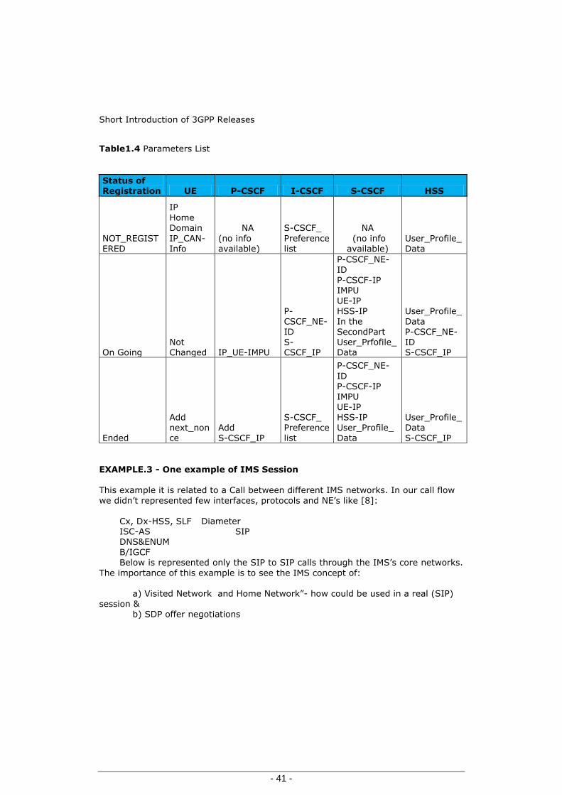
Short Introduction of 3GPP Releases
- 41 -
Table1.4 Parameters List
Status of Registration UE P-CSCF I-CSCF S-CSCF HSS
NOT_REGISTERED
IP
Home Domain
IP_CAN-Info
NA
(no info available)
S-CSCF_
Preference list
NA
(no info available)
User_Profile_Data
On Going Not Changed IP_UE-IMPU
P-CSCF_NE-ID S-CSCF_IP
P-CSCF_NE-ID P-CSCF-IP IMPU
UE-IP HSS-IP In the SecondPart User_Prfofile_Data
User_Profile_Data P-CSCF_NE-ID S-CSCF_IP
Ended
Add next_nonce
Add S-CSCF_IP
S-CSCF_ Preference list
P-CSCF_NE-
ID P-CSCF-IP IMPU UE-IP HSS-IP User_Profile_Data
User_Profile_Data S-CSCF_IP
EXAMPLE.3 - One example of IMS Session This example it is related to a Call between different IMS networks. In our call flow
we didn’t represented few interfaces, protocols and NE’s like [8]:
Cx, Dx-HSS, SLF Diameter ISC-AS SIP DNS&ENUM B/IGCF
Below is represented only the SIP to SIP calls through the IMS’s core networks.
The importance of this example is to see the IMS concept of:
a) Visited Network and Home Network”- how could be used in a real (SIP) session &
b) SDP offer negotiations

Chapter-Telecom networks from GSM to IMS
- 42 -
Figure 1.15 Call between SIP to SIP (here are involved different IMS networks) [8]
Visited-Net-BHome-Net-BHome-Net-AVisited-Net-A
Invite1stSDPoffer
Invite1st SDPoffer
InviteInvite Invite
Invite1st SDP offer
100 (Trying) 100 (Trying)100(Trying)
100(Trying)
100(Trying)
183 SessionProgress 1st SDP Answer
PRACK 2nd SDP offer
200-OK 2nd SDP answer
UPDATE 3rd SDP offer
200-OK3rd SDP answer
180Ringing
PRACK
200-OK
200-OK
200-OK
ACK
ACK
180Ringing
P-CSCF S-CSCF P-CSCFS-CSCFI-CSCFUE-A UE-B
Media User-Plan (on IPCAN)
SIP session (see Figure 1.15) is initiated by an “INVITE” and (could) contain
proposed media offers (SDP-Offer will be negotiated). The basic rule of SIP routing
was specified on RFC 3261 and is based on:
a) UAC sends the request to SIP local Proxy
b) Visited P-CSCF route the call to home network of Calling(UAC) based on saved info during UAC Registration ->till to the UAC-S-CSCF Home-Net-A(the IP of S-CSCF Home it is present in Visited P-CSCF as Service-Route)
c) S-CSCF Home Net-A( after ENUN query-depend on the implementations)
perform DNS query/lookups for UAS-URI requested d) Based on the DNS response, in the next step S-CSCF of UAC will do the
routing to the home domain of UAS-> to I-CSCF from Home-Net-B-> home of Called(UAS)

Short Introduction of 3GPP Releases
- 43 -
e) I-CSCF -SIP proxy from home domain will perform SLF/HSS Diameter query and route the request to S-CSCF Home-Net-B-> home of Called(UAS)
f) S-CSCF-Home-Net-B act as registrar, replace the Public URI of Called (UAS)
with the contact address that Called( UAS) has it registered and route the request to UAS via visited P-CSCF-> from Visited-Net-B ( IP of Visited-Net-B- P-CSCF it is saved as Path on S-CSCF from Home-Net-B of Called -UAS after its registration)
And after SDP (Session Description Protocol) negotiation and last ACK Media
Path will be established via its dedicated Path. Until now it was introduces the IMS registration start from LTE, and it was highlighted the main steps of a Call Session start from Visited Net-A and finalized on Visited Net-B(see above example)
In the end of our Calls scenarios presentation, will be done a small description of HO (Hanover) 4G to 2G based on Rel-10 that to underlined the improvements of this one

Chapter-Telecom networks from GSM to IMS
- 44 -
EXAMPLE.4 - SRVCC from 4G to 2G without DTM support
From 3GPP TS 23.216 V10.1.0 (2011-06) below in Figure 1.16 is presented a Call flow for SRVCC- (Single Radio Voice Call Continuity) from 4G E-UTRAN –LTE
to 2G- GERAN without DTM (Dual Transfer Mode )support. The functionality of this transfer has a high complexity and it is based on many specifications. The migration to ALLIP network will take many years.
Figure 1.16 Call SRVCC from 4G to 2G without DTM support
E-NODESource
UE MMESource
MSC-ServerMGW
Target-MSC Target-SGSN Target-BSSS-GWPDN-GW
IMS
1Measurement
reports 2.DecisionHO
HandoverRequired
3
4.BearerSplitting
5
PS to CS Req Prep-HO-Req6
HO-Req/ACK7
8Prep-HO-Resp
9
Establish Circuits10.Initiation of SessionTransfer-STN-SR or E-STN-SR-Invite
11.SessTransfUpdateRemoteEnd
12.Release of MS access leg
13.PS to CS Resp14.HO Command
15.HO from E-Node Command
16.UE tunes to Geran
17. Handover Detection
18.Suspend (see TS 23.060) 18.Suspend
18.Suspend Req/Res 19.HO Complete20.SES-HO Complete
21.Answer22.PS to CS Complete22a.Bearer handling and suspension
23a.TMSI Realocation
23.b Location Update HSS/HLRGMLC
24.Subscreiber Location Report
*From operation 10 STN-SR Session Transfer Number for SR-VCC -see TS 23.237 E-STN-SR Emergency Session Transfer Number for SR VCC-see TS 23.237
Detail about IMS architecture could be find in Figure 1.12 IMS, there are represented ATCF (Access Transfer Control Function) and ATGW (Access Transfer Gateway) these both are located in the serving network. With the help of this two new components, the domain transfer will be improve in order to minimize the speech interruptions ( if any) in the most worst scenario of

Short Introduction of 3GPP Releases
- 45 -
roaming(visited network) when the delay of path handover could lead to this interruptions[12][13].
How also the names of this both components anticipated: ATCF will be present in the CP path on I2 interfaces, anchoring of SIP session & ATGW will be present in the UP path on Mb interfaces, anchoring of RTP packets
The real improvement its realized because the session transfer leg sent from
that MSC-Sever ( presented also like SRVCC-enhanced MSC server) not need to be
send and routed to the home network (potentially delay due long distance) , just will be routed in the same serving network using ATGW for RTP with help of ATCF which will control it.
These complex scenarios will persist many years in telecom new networks. That because the migration to All-IP network will take many years. Even one operator already did this migration for inbound/outbound roaming the CS
network and CS customers’ profiles / HLR functionality has to coexist a long time, till the operators from many countries will finalize the migration. For this reason the migration to ALL-IP will traverse this complex phase; it will be new and old mobile networks, (4G) and (2G-3G) under IMS, using ICS, SRVCC and FMC concepts.
The complexity of future IMS Networks could be observed in Figure 1.12
even there are represented only the mobile networks components. How we can see, under IMS (ICS) and based on SRVCC it will be possible to have the old networks working in interconnect with the new generation even these are from different vendors. In this moment it is necessary to have a unified solution for quality managements, fault management cases and network and services optimization. In our opinion the only one unified solution, which can offer all possibility of verification, including also a deeper and in details analysis of the unified network,
and how it is already specified, could be, only one based a permanent Tracing System of protocols and networks interfaces (see also chapter 2 and 3).
Later on the chapters 2, 3 and 4 we will show, how could be use it or how it is possible to have network managements tool for all categories of users, within one telecom company.

Chapter - Network Management
- 46 -
2 Chapter - Network Management
Network management is a very important domain of activity in telecommunications. We can define easy this domain mentioning its components. Network management consisting of five sub domains:
1-FM - Fault (and Optimization) Management 2-PM-Performance Management 3-CM-Configuration Management
4-AM-Accounting -Charging Management 5-SEM-Security Management / In IMS (generally in IP world) - Security has to play a central role
All these components have a strong interdependence (ex. FM with PM or CM) but in the same time representing something specific inside of Network
Management.
2.1 Network Management sub-domains 1 - Fault Management, FM. The main components of FM are:
- Fault alarming and reporting - Fault detection - Maintenances procedures - Tests of Network (auto tests) &Service Quality
As typical Fault Management actions could be seen:
a) Reactive FM based on the Customer Care & Surveillance Network Teams chain information received directly from networks’ customers or based on alarming system of networks and quality of services. These existing teams or departments are playing a very important role in relation of each Service Provider with its customers. This is realizing using the following FM components: - Fault alarming and reporting (PM reporting also)
- Fault detection - Maintenances procedures b) Proactive FM based on maintenance preventive actions: these are including networks elements from HW hardware / SW – software point of view and also quality of services. This is realizing using the all FM components: - Fault alarming and reporting (PM reporting also)
- Fault detection
- Maintenances procedures

Network Management sub-domains.
- 47 -
- Tests of Network (auto tests) & Service Quality To be able to take actions inside of FM activities (Reactive or Proactive) the
services provider are using their dedicated tools from classical OSS (Operation Support Subsystem, like PM reports or alarming). A powerful tool used in the difficult cases is the Tracing System (equipment trace) of Network interfaces and protocols (for tracing tools concept, see chapter 3). The equipment trace “provides very detailed information at call level on one or more specific mobile(s). Trace plays a major role in activities such as determination of the root cause of a malfunctioning
mobile, advanced troubleshooting, optimization of resource usage and quality
…“[35].
2 –Performance Management, PM, domain has following processes-components: - OMs - Operational Measurements production - OMs - Data collecting and processing - Alarming –based on standard threshold based on best experience. These alarming and PM OMs are used for FM and Optimizations of network AND services and on
reengineering capacity. 3- Configuration Management, CM, is a main activity for operational’ network personals but not only for these. In these actions are involved also the vendors and entire technical-teams chain of Service and Providers (Engineering-Operation-Surveillance). The right design, dimensioning and configurations of network and
services create the base of customer’s satisfactions and could avoid the future FM operations. The main components of CM are: - Network and Interfaces (O&M, UP, CP, etc.) configurations (HW-SW) - Subscribers Provisioning - UE and CPE (Customer Premises Equipment) automatically configurations based on
services, subscribers profile and users equipment type (CPE also). This last step regarding UE automatically configurations per services, subscriber profile and UE type has to be extended because it is helpful and offer a plug and play components with a big satisfaction for the customers, avoid in the same time potentially users complains.
4 - Accounting -Charging Management, AM has the components:
- Data Generations or Events and Call Data Records generations is a step done in the networks elements having different format (depends on Vendors) in the most cases. - Data Mediations and Collections process is responsible to collect all generated data and in the end (after on demand corrections - if it is the case) will changed in the unified billing format.
- Data Rating will be done the correlations to the existing tariffs of the telecom companies. - Bill Generation will be done pro customer and pro bill period. The Data Generated in this domain could be used and are in use by many Network and Service Provider for FM purpose. It is clear that this a valid input for any CEM or in the creations of company’s clouds or also like a very valid tool under the many CSA tools. But in the same time we had to know that this one has a limitation, it is referring only to
Subscribers Calls actions not more and not less.

Chapter - Network Management
- 48 -
For example in the cases of Registration (Figure 1.14) issues we can have any information or other networks quality issues.
In the conclusion even using the Accounting Data we can’t cover entire FM area, this source is a very precise and valid input, make sense to aggregate or correlated this Data with others source of information delivering in this way a
complete overview of possible FM issues. 5- Security Management, SEM. Using all rules specified under Security Management
sub domain the networks and services provider could assure their network’ safety and services functionality and the privacy of each customer. In the same time this subject is very large and inside our present work will bring only a little information about it, trying to highlight the importance and the complexity of this one. In IP
world this one, it is a very important and actual aspect, that because of interconnections to the other IP networks and even more, if this network is connected to the Internet (exactly the case of IMS). Today we are living the beginning of interconnected communication world, but in the future this will became reality, and the security management could became a separate domain, because the magnitude and importance of future requests. Summarizing, an IP network could be
protected using: - Hardware components - Software methods - Applications.
Like Hardware components we can mention:
- Firewalls: assure against intrusion attack from the other networks/Internet but are not able to do anything against Viruses and Spam - ALG: Application Level Gateway (could be also only SW components within Firewalls) - SBC: Session Border Controlling, like a trendy components is using in IMS. Looking like SBC is adding compare to other HW security dedicated equipments few benefits:
a) CP-Control Plane and UP- User Plane security b) Control of quality of service c) Gateway functionality for the codec’s
Software methods and applications:
- Authentication see Figure 1.13 LTE Attach & Figure 1.14 Initial-Registration
the presence of Authentication the explanation regarding Digest
- Authorization see Figure 1.13 LTE Attach- there was mentioned Radius Authorization
- Encryption has many possibility and components; we will start from LTE
with NAS-Non Access Stratum-encryption algorithm- see Figure 1.13 LTE Attach
- LTE-NAS Encryption-Security protection of NAS messages has the two aspects: -ciphering -integrity protection: must be used, being mandatory (as defined by 3GPP
documents).

Network Management sub-domains.
- 49 -
Encryption or Ciphering of NAS messages is an optional part of the 3GPP
documents (to disable/enable NAS ciphering it may choose the null/real ciphering algorithm - according to 3GPP TS 33.401 Annexes B.0, B.1). However, if NAS ciphering is disabled, the MME will not have IMEI information. Therefore, NAS ciphering shall be enabled from the beginning. In 3GPP TS 24.301, NAS protocol for EPS (Evolved Packet System) has three options for NAS messages encryption on S1 interface:
EEA0 null ciphering algorithm. This does NOT require retrieving keys from
S6a and applying them to S1-AP to make the de-ciphering,
128-EEA1 EEA1 is a stream cipher based on another stream cipher named
SNOWS 3G. EEA1 is an inheritance from UTMS and was introduced
as 3GPP standard on 2006.
128-EEA2 EEA2 is a stream cipher based on the block cipher AES algorithm
used in its CTR mode.
Other CP encryption algorithm - SSL-Secure Sockets Layer (with variants) first introduced via the Netscape
browser
- TLS-Transport Layer Security (RFC2246) provides transport layer security for Internet applications [8]. TLS it is builds on SSL it is able to replace it. If one system can support both of them, it can start to use SSL and if UAC request can switch to TLS (this switch can be done by request in both direction SSLTLS - UP Encryption
- SRTP-Secure Real-Time Transport Protocol – can be used to secure RTP media stream. Based on the negotiation method one UE let say UE-A request SRTP and if the destination will accepted and support it, the Media will be encrypted. To be fully secure in the case of using SRTP on Media (UP) it is indicated also on CP (SIP) to use TLS to encrypt the SIP headers. - S-MIME-Secure-Multipurpose Internet Mail Extensions. Using S-MIME, SIP will be
able to encrypt SDP dedicated parts, that to assure the privacy of information. - UP&CP encryptions - IPSec-Internet protocol security [8], with the components in RFC 2406. IPsec operate in two modes:
Tunnel mode -the full datagram is protected Transport Mode -for IP headers protections
With IPSec help were implemented a lot of VPN – Virtual private Network (in this way in IT world it was realize a secure communication). Others Method of Protections - NAT -Network Address Translation is used in the most of the case when the user needs access to the internet from his private network. The idea behind of this concept it is, never show to the internet the real address used in internal network
and “never” used outside the same external IP. It is not so easy, even if we are referring only to the basic NAT is necessary to change: -IP addresses (internal addresses) -IP header checksum &
-any other checksums where the IP address could be included

Chapter - Network Management
- 50 -
The NAT-method choose depends on the applications purpose, upper layer protocols content and transport protocols in use (NAT services- is presenting in many case to the firewalls or routers). - DMZ -Demilitarized Zone controlled by the firewall, a security concept used today in the most of the companies.
- Attacks and Responses: we found very interesting from network’s security point of views; the definitions and classifications of attacks type and the network responses preparation having dedicated team of engineers.
In our opinion in the future and also now, the big challenge of network security is to learn in advance (anticipative learning), to prepare in advance the concept of security, with others words to have the right dedicated security equipments, the right software implementation and having the dedicated
engineering personals acting in the necessary place and practically in real time (in the end obtaining the right results). The idea is to avoid any damage and to avoid learning by shocks. Each component mentioned could present a lot of advantages for the purposed tasks and also could create a lot of restrictions and issues. Until now we don’t know if somewhere it was found the perfect combination or final choice within this domain, with respect of all security rule and having only the
advances.
2.2 IMS-Network Management End to End
A unified network under IMS represents a chance for telecom to standardize and unified its network management. This existing concept [21] is already accepted, it is already under implementation and even in use. Anyway, for the transition phases to all-IP networks (could take many years because of roaming agreements) it is necessary to unified as more as possible from the networks managements sub-domains.
In the first phase we will have together under IMS: new mobile networks
(4G), old MOBILE networks (2G-3G), FIX networks and non3GPP networks (and using ICS, SRVCC and FMC concepts even are from different vendors). For this combination new–old and different vendors make sense to unify as much as possible existing and separated Network Management components. That is necessary because, under IMS we are trying to offer e2e services and their continuity; for this
reason the networks and services provider need from the beginning, e2e power full tools, independently from networks vendors, capable to deliver deepest detailed information and in the same time an overview of the networks and services in “real and back time”. A short analyze of Figure 1.16 “Call SRVCC from 4G to 2G without DTM support” conducts to above directions. Using of these tools the networks and telecom services providers have to be able to: 1-analyze the cases start form each customers and group of customers
2-detect possible issues of network and services in advances 3-localise exactly the points and causes of issues 4-take the right decision on dimensioning, configuration and maintenance 5-lead new projects and network extensions
Unifications processes could reduce the time and the investments to train
personal from and for: surveillance, maintenance, security, optimization and
engineering.

IMS-Network Management End to End
- 51 -
In our opinion in the transition phase following sub-domains of Network management could be unified from the beginning:
1-FM -Fault (and Optimization) Management 2-PM -Performance Management 3-AM -Accounting-Charging Management could be done after
reconsideration of architecture (like new concept to be integrated OCF,OFCS) and/or data format
4- SEM -Security Management
5- CM -Configuration Management could remains as an open problem
Anyway in the case of all-IP, these CM tools (OMC’s – operations and management’s center) have to be unified using the same standards for: a)OMCs graphical user interfaces outputs b)OMCs commands modus
For this convergence/unification of Network Management sub-domains, the communications company must to reach: -Short time for rebuilds, flexibility and interchangeability of the teams - inside or
outside (of course the dedicated engineer’s teams shall have the good knowledge specific to the network domain where they are working – e.g. IP-CAN and IMS). -Easy cooperation and interpretation of information between different network domain’s team in the case of issues, new projects and re-dimensioning and re-engineer.
This will lead the company to achieve the necessary resources in the right
directions: -Quality of networks -Quality of services -Services (Customer Oriented)
This NM convergence is not only the trend but a necessity, for example under ICS, radio planning 2G-3G-4G must to use the same tools (see-Figure 1.16 - in the case of HO 4G-2G) -the convergence of the radio planning tool is mandatory.
And also to assure an easy: -ANSC-analyzing of network and service continuity -Cooperation and interpretation of information Intra/inter teams and intra-inter sub domains of the network in case of: a)New projects b)Re-dimensioning c)Re-engineering
d)Issues In our opinion from the beginning, in the transition phase must be unified
following sub domains of Network management: 1-FM - Fault (and Optimization) Management 2-PM-Performance Management
Optimal will be to have an implementation which could offer the necessary
information for all users from a Telecom company. It is necessary to have if is possible “all in one”.
This tool has to cover, all levels of user’s requests and all legacy networks (all network domains) which will be presented under ICS.
In our opinion the only one unified solution, which can offer all possibility of verification, starting from deeper and in details analysis of the unified network, it is
one having at the base a permanent Tracing System of Protocols and Networks
Interfaces (see also chapter 3).

Chapter - Network Management
- 52 -
2.2.1 Tracing Systems tool
The main 3GPP specifications related to this domain are: TS 32.421-"Subscriber and equipment trace: Trace concepts and requirements"; TS 32.422-"Subscriber and equipment trace: Trace control and configuration management”;
TS 32.423-"Subscriber and equipment trace: Trace data definition and management";
Conform to the 3GPP TS 32.421 V10.3.0 (2011-09) (Introduction): -Subscriber and equipment trace provide very detailed information at call level on one or more specific mobile(s) -This data is an additional source of information to Performance Measurements -Subscriber and UE Trace is the easy way to go deeper into investigation and UMTS network optimization Contrary to Performance measurement:
-Trace is activated on user demand- for a limited period of time for specific analysis purposes (PM are a permanent source of information) -Subscriber and UE Trace give instantaneous values for a specific event (e.g. call, location update, etc.) (Without history- no values aggregated on an observation
period)”
3GPP Trace concepts and high-level architecture The high-level architecture of tracing services was defined in 3GPP TS 32.421. Below are some information about architecture of tracing activation and trace reporting, based on information from 3GPP TS 32.421 V10.3.0:
a) Trace activation at the UE b) Trace activation at an IMS NE c) Architecture for Trace Reporting from UE d) Architecture of Trace Reporting from NE
a) Trace activation at the UE
In the figure 2.1 we have represented the propagation way of trace
parameters configuration and the trace parameter propagation. Here as central element is the UE in interconnections with an Element
Manger( via network), and than UE –NE( Network Element) in the second part of trace parameter propagation.

IMS-Network Management End to End.
- 53 -
Figure 2.1 Trace activation at the UE
Trace Parameter Configuration Trace Parameter Propagation
ElementManger
NetworkElement
NetworkElement
NetworkElement
UE UE
The activation/deactivation of the trace has two components:
-Management based action -Signaling based actions Trace Parameter Configuration is a Management based action & Trace Parameter Propagation is a Signaling based action.
Trace Parameter Propagation start point is any signaling actions of UE for
the defined period of time. b) Trace activation at an IMS NE Fallowing the same logical steps like above, we will continue with the case of - Trace
activation at an IMS NE (even the elements involved remain more ore less the same)
It is the same idea only that in this case the trace parameters configurations are first of all done in one NE (Network Element). Observation: in our representation we have only the external EM, but in the specification the EM (Element Manager) can be embedded NE.

Chapter - Network Management
- 54 -
Figure 2.2 Trace activation at IMS NE
Trace Parameter Configuration Trace Parameter Propagation
ElementManger
NetworkElement
NetworkElement
UE
c) Architecture of Trace Reporting from (NE&UE)
Very important it is the way of Traces reporting and collection. Enclosed a high level architecture dedicated to this action in Figure 2.3 Trace activation at an IMS NE Figure 2.3 Trace Reporting
ElementManger
NetworkElement
NetworkElement
NetworkElement
TraceCollectionEntity

IMS-Network Management End to End.
- 55 -
The traces reports-collections could be done:
1) From NE- Network Element through EM- Element Manger, after that in the second to Trace Collections Entity and/or
2) Directly NE to Trace Collections Entity UE could also report its traces see Figure 2.4
Figure 2.4 UE trace Report
NetworkManger
UE
In the telecommunications area, are existing companies [20]which have already implemented something in this direction, but based on SIM / USIM (applets) applications and delivering the reports via:
- SMS - Data Transfer (PDP context). An also the delivered reports are not the traces, are only few dedicated results of measurements. Advantages of this 3GPP trace concept: - No specials tracing equipments necessary (EM and Trace Collections Entity are
delivered from NE vendor) - No specials rules of correlations - No special investments
Disadvantages of this 3GPP trace concept: - No history – traces availability only for the specified limited period
- In the cases of customers complains – necessary failure reproductions and based on customers time Availability - No links/interfaces Traces - No permanent source of traces - In the case of not adequate activations mode -could be created issues on the Network
- Not guaranty of tracing availability in the case of Network issues-let say in the case of Network overload or peak our -Exactly when is necessary - Limited ways of usage and personals usage - Dedicated specialists to activate/deactivate them - Practically in use only for Net-Maintenance personals
- No guaranty of functionality and different output -for Different vendors of different networks sub domains network

Chapter - Network Management
- 56 -
- For each case of inter networks sub domains tracing – coordination of trace activations is necessary - Interdependency from networks vendors
2.2.2 Justification concept of One network one Tracing system
The calls scenarios included in the subchapter 1.16 (see Figure 1.16) help us to
justify easy our concept “One Network one Tracing System” (see also chapter 3). Starting from presented example in Figure 1.16, under already specified IMS network and ICS concept, for a long time will remain together the “old” Mobile networks CS and the new LTE. With help of FMC (Fix Mobile Convergence) concept
the mobile and the fix networks will be able to deliver the same services. That means for the customers new services and a comfortable ways of using. But in the same time the complexity of the network will be very high. The operators need dedicated tools to investigate deeper and in details the “future” interconnected network (3GPP and non 3GPP also) and services’ let say, for optimisation purpose and also in the cases of mall functionality.
This could be done very well with help of a UPTT (Unified- Permanent-Tracing-Tool) based on followings concepts see Figure 3.6 (details also in chapters 3&4):
a) Distributed Probes (Analyser of interfaces an protocols) and Central data
base where: - Probe-collect saved for a specified period of time all details from
Protocols and Interfaces - Data base servers – collect and save, for a specified period of time(days) the Data -Traces in short format like, Call Data Records, Call Sessions, Events- depends from which protocols and which layer protocols is done
b) This system could be used like :
- Real time tracer - Back in time tracer- based on saved period in time - Permanent source of information
c) To cover as much is possible, the operator network domains with the same
tracing tool, that to assure easy way of analysis and network reengineering- “Continuity of Network Analysis” and easy unified
interpretation based on the same outputs of the results
d) New concept of inter protocols correlations and interfaces, e2e per domains, with definitions of new concepts –“borders (islands)” tracing of interconnected domains
e) To be used like a source of new Customer Service Assurance (CSA), Customer Experience Management (CEM) and Clouds tools.
f) Based on open architecture and scalability, to create/ to aloud creation around its Customer Experience Management (CEM), Customer Service Assurance (CSA) and or Clouds tools

IMS-Network Management End to End.
- 57 -
g) To be able to assure a e2e networks and services deeper analysis, optimisations and management, independently from the networks vendors -
even independently from coexistence of many different technology (vendors) in the same network and in the same time
h) Recovering and pushing of UE permanent identifiers in the protocols
operations, events and protocols even these, are not there presented
”Tracing on demand all cases all protocols using easy interrogations and
correlations “
i) Tracing Systems- resources optimizations and optimisations of its usages(because of traffic increasing „explosions”)
j) The Monitoring Points to be predefine and available in the networks
components as its parts let say monitoring interfaces –to be standardised(task for networks vendors)

Chapter - Tracing system and CSA
- 58 -
3 Chapter - Tracing system and CSA
The third chapter is presenting the main provocations of the tracing platform
starting from IP-CAN (IP Connectivity Access Network), CP&UP (Control Plane &
User Plane) taking in consideration all components like: real time reporting,
alarming Performances managements, all these linked with the drill down till to the
deeper analyzing of interfaces and protocols through the traces having the intra and
inter protocol correlation using the concept of E2E analyzing.
To see much better the way from UPTT (Unified-Permanent-Tracing-Tool to Customer service Assurance) we are using here manly the article “A Customer Service Assurance Platform for Mobile Broadband Networks”. This paper appears in:
Communications Magazine, IEEE Oct. 2011[36].
This paper is a result of many years of work and team work of Telecom-Operator, Vendor and Academia.
With other words it is a result based on: -Real and deeper requests
-Theoretical definitions -Exactly implementations -Practical testing verifications in the real network and on demand even -Rework and Redesign
In this paper, were discussed trends, issues, requirements and solutions for Customer Service Assurance (CSA) platforms for mobile broadband networks. Here
it was proposed a distributed probe-based architecture called iCSA (intelligent CSA), and demonstrate how it is a key component of an advanced OSS (Operational Support System). iCSA provides support to OSSs, addressing a number of important issues: increase of bit rate, joint analysis of control and user plane, multi-dimensional analysis, root cause analysis, etc.
To provide real evidence of the benefits of our proposals on a real mobile broadband network, we also illustrate experimental results on two hot topics:
- Mobility and Session Management
- Root Cause Analysis of TCP connections.
The traffic over mobile networks has been strongly increasing due to the growing number of users, terminals (i.e., Smartphone and tablet), and applications (i.e., video streaming and social networks). At the same time, mobile operators are facing several challenges in their value chain (e.g. increase in the infrastructure management costs, reduction in the average revenue per customer, etc.), while sustaining the migration towards Evolved Packet Systems Architecture [51].

- 59 -
Due to a plurality of access and core network technologies being used to deliver a complex set of services, setting-up and running mobile broadband
networks is becoming increasingly complex. In addition, increased competition and customer churn are driving service providers to be even more customer-centric and innovative with their services.
In this evolving scenario, both industry and academia are paying their attention more and more to CEM (Customer Experience Management) and CSA
(Customer Service Assurance).
CEM refers to the collection of processes an operator uses for tracking,
overseeing, and organizing every interaction between a customer and the organization throughout the customer lifecycle (from service support to new sales, from trouble resolution to billing inquiry, etc.).
CSA refers to the part of CEM that deals with service quality, a measure of how individual users experience the services they purchase [40]. As a result, CSA
platforms – supporting the Operational Support System (OSS) – are indicated as a mandatory ring in the management chain for mobile broadband networks and they are consolidating in a clear framework [40] [41].
While mobile broadband networks are completing their transformation in fully packet-based architectures, traffic monitoring systems (based on passive
probes) are continuously evolving. They are experiencing a continuous shift towards being a key tool in the area of CSA platforms, able to track and manage mobile subscribers’ experience, when properly fed and configured [42].
OSSs market analysis positions probe-based traffic monitoring systems into
the ecosystem of Service Assurance, alongside other OSS applications for Fault Management, Performance Management and Service Quality Management [43]. The
Service Assurance market has generated $2.3 billion revenue in 2009 and it is forecasted to grow up to $3.4 billion in 2014, resulting in a CAGR (Compound Annual Growth Rate) of 8.3% [43]. Probe-based systems are the largest sub-segment in terms of revenue and it is estimated to increase from $843 million in 2009 to $1.18 billion in 2014, a CAGR of 7% [43].
The market of mobile telecommunication services and, consequently, mobile
network operators are facing the following challenges, which will tend to increase in the upcoming years: (i) a dramatic increase in cost and complexity for managing mobile networks and services;
(ii) the need for heavy investments in infrastructures to meet the growing demand of data communications, while radio access capacity is not scaling accordingly [44]; (iii) a reduction in average revenue per customer (average revenue per user); (iv) a shortage of human resources with the appropriate skills to manage the growing complexity. These changes will necessitate a number of macro-
requirements for OSSs, which will focus on:
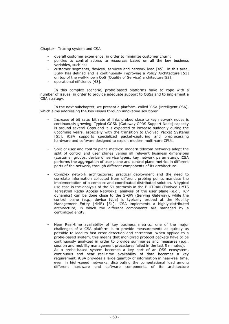
Chapter - Tracing system and CSA
- 60 -
- overall customer experience, in order to minimize customer churn; - policies to control access to resources based on all the key business
variables, such as: - customer segments, devices, services and network load [45]. In this area,
3GPP has defined and is continuously improving a Policy Architecture [51] on top of the well-known QoS (Quality of Service) architecture[52];
- operational efficiency [43].
In this complex scenario, probe-based platforms have to cope with a
number of issues, in order to provide adequate support to OSSs and to implement a CSA strategy.
In the next subchapter, we present a platform, called iCSA (intelligent CSA),
which aims addressing the key issues through innovative solutions:
- Increase of bit rate: bit rate of links probed close to key network nodes is
continuously growing. Typical GGSN (Gateway GPRS Support Node) capacity is around several Gbps and it is expected to increase suddenly during the upcoming years, especially with the transition to Evolved Packet Systems [51]. iCSA supports specialized packet-capturing and preprocessing hardware and software designed to exploit modern multi-core CPUs.
- Split of user and control plane metrics: modern telecom networks adopt the split of control and user planes versus all relevant business dimensions (customer groups, device or service types, key network parameters). iCSA performs the aggregation of user plane and control plane metrics in different parts of the network, through different components of its architecture.
- Complex network architectures: practical deployment and the need to
correlate information collected from different probing points mandate the implementation of a complex and coordinated distributed solution. A typical use case is the analysis of the S1 protocols in the E-UTRAN (Evolved UMTS Terrestrial Radio Access Network): analysis of the user plane (e.g., TCP dynamics) can be done close to the S-GW (Serving Gateway), while the control plane (e.g., device type) is typically probed at the Mobility Management Entity (MME) [51]. iCSA implements a highly-distributed
architecture, in which the different components are managed by a centralized entity.
- Near Real-time availability of key business metrics: one of the major
challenges of a CSA platform is to provide measurements as quickly as possible to lead to fast error detection and correction. When applied to a probe-based system, this means that monitored protocol packets have to be continuously analyzed in order to provide summaries and measures (e.g., session and mobility management procedures failed in the last 5 minutes). As a probe-based system becomes a key part of an OSS ecosystem, continuous and near real-time availability of data becomes a key
requirement. iCSA provides a large quantity of information in near-real time, even in high-speed networks, distributing the computational load among
different hardware and software components of its architecture

CSA platform based on a Tracing System
- 61 -
- Root cause analysis: the last major challenge is related to the quick identification of root-causes by using proper metrics and analysis tools, e.g.,
“Is the service problem affecting this segment of users in the network or not?”, “Is the network affecting the performance of this TCP connection?”, etc. Advanced data manipulation and presentation capabilities, together with innovative techniques for user plane analysis, allow iCSA to provide fast and accurate answers to these questions.
There are three main approaches or perspectives to Service Assurance that
have emerged over time [53] and [54], and [40]: - Resource-centric, - Service-centric & - Customer-centric. Each of these approaches has strengths and weaknesses and not a single
method by itself can provide a fail-safe and effective way to CSA. Modern networks require a combination of all three assurance models to fully monitor report and
troubleshoot problems. This combined approach, as described in §3.1, is adopted by the iCSA platform.
Different measurement methods may be used for implementing these approaches: - element-based, in which performance measurements are directly reported by network elements;
- terminal-based, in which software agents are placed on user equipment; and - probe-based, in which data is passively collected, capturing the traffic flowing through the network.
This method allows visibility on the entire multi-vendor network, without adversely affecting the components of the network or installing intrusive software on the user equipment. iCSA is a probe-based system.
3.1 CSA platform based on a Tracing System
In order to cope with the issues already presented in this chapter, we propose a probe-based CSA platform called iCSA- Intelligent Customer Service Assurance, which provides deep analysis and cross-relational capabilities across the network, services, devices and subscribers. As depicted in Figure 3.1, the two main components of the platform are the iCSA Central Server (single or multiple) and iCSA Probes. iCSA can be enriched with external data sources (e.g., information on devices, services and customers) and can be integrated into external management systems.
The iCSA Central Server (Figure 3.1) consists of the following key sub-systems:
- the iCSA Server Platform - iCSA Applications. End users can access the iCSA applications by means of Web clients. The iCSA
Server Platform is a set of distributed components that receive extended Data Records (xDRs) from all the iCSA probes. With the term xDR, we mean a summary containing the most important information regarding each single transaction. Such a
transaction could be related to both the control and user planes of a simple call, an

Chapter - Tracing system and CSA
- 62 -
Intelligent Network request, a Session or Mobility Management transaction, a TCP connection and so on (SCTP,UDP).
Figure 3.1 High-level view of the iCSA architecture.
The iCSA Server Platform implements capabilities, exploited by the iCSA or other OSS applications:
Retrieval of both xDRs and raw frames from probes (captured by the data collector and by the data collector server proxy, respectively).
Binding of xDRs pertaining to the same transaction and enrichment of their content by means of external information (performed by the Binding/Enrichment function).
Computation of different measurements, at different levels, such as
Elementary Counters, Key Performance Indicators, etc. (performed by the Data Management function).
Optimal storage of xDRs (performed by the iCSA central database).
Interface towards external data sources and external OSS applications.
iCSA Applications access and manipulate data available across the iCSA platform for different purposes: Troubleshooting: analyze specific protocol sessions by retrieving xDRs
pertaining to this session. This requires searching within a large distributed database of xDRs: for a mobile operator several hundreds xDRs per active user may be stored every day.

CSA platform based on a Tracing System
- 63 -
Multi-dimensional analysis: analyze, for planning and optimization purposes, relevant counters related to the amount and quality of network procedures and
services, through different multi-dimensional views, such as network, customer groups, device types and areas, etc. Counters are also combined into KPIs (Key Performance Indicators), inheriting multi-dimensional views.
Proactive monitoring of the network: monitor continuously the health of the network and related services, and trigger alarms in case of issues in key
network elements, services or customer groups such as corporate accounts, VIPs, etc.
Figure 3.2 The Probe
Figure 3.2 summarizes the architecture of the iCSA Probe and highlights its main components:
- Packet Capturing and Processing: this module interfaces with the links
connecting the nodes of the network being monitored. It is a dedicated acquisition card, with custom firmware and drivers: it provides in-hardware time-stamped output packets, with an accuracy of microseconds, and it is able to analyze tens of Gbps of traffic. Moreover, it may implement in-

Chapter - Tracing system and CSA
- 64 -
hardware packet filtering for the probe to analyze only the portion of relevant traffic, thus off-loading the CPUs (see §3.2 and chapter 4).
- xDR Generator: this component decodes and analyzes time-stamped
packets, generates statistics at the protocol layer (messages and events counting) and xDRs. For each new transaction, the xDR generator builds a new record and keeps it in memory. When the transaction reaches a significant phase (e.g., start and end of a call or of a TCP connection,
timeout expiration, etc.), the xDR generator closes the record and stores the data in the local storage system. The xDRs are then transferred to the iCSA central server. In order to properly generate the xDRs, the state machine of
each protocol is implemented, which allows messages pertaining to the same transaction to be bound (e.g., message related to the same Packet Data Protocol (PDP) context) and thus to relate subsequent xDRs, which represent the state evolution of a certain session.
- Storage: this component implements an indexed storage of low-level protocol statistics and alarms, raw frames and xDRs. The xDRs are continuously transferred to the iCSA Central Server, while a long-term storage of raw frames and alarms is provided by the probe.
- Application Interface: this component acts as a proxy for requests coming
from applications (mostly in the area of the troubleshooting) that require access to statistics/alarms and frames.
The hardware of the iCSA probes is based on high-end server technology that exploits multi-core processors. The number of cores ranges from four to twelve,
depending on the traffic and on the complexity of the requested analysis, while RAM capacity varies in the range of 4–16 Gigabytes. Storage availability can be configured in the range of 1–28 Terabytes. The software of the probe is designed so that it tracks the continuous evolution of server technology, especially in the area of multi-core processors. Acquisition cards are specific to the transport technology in use in the network under analysis (PDH, SDH, Ethernet, etc.). For mobile broadband networks, Ethernet is the dominant technology; while Gigabit Ethernet is the most
common case, 10 Gigabit Ethernet is gaining momentum.
The iCSA probes can monitor protocols at any access and at any core network interfaces of 2G-3G mobile networks and of Evolved Packet Systems, and in the IP Multimedia Subsystem (IMS).
3.2 Details about working mode of the new CSA
The iCSA monitoring chain starts within the probes. xDRs are continuously transferred to the server, while raw protocol messages are stored in the local probe hard disks and then transferred to the server only on demand (e.g., when users are
performing detailed troubleshooting analysis and require their visibility). This avoids the exchange of large amounts of data between the probes and the server during on-line monitoring. In the iCSA Central Server, xDRs are subject to an initial preprocessing (see Figure 3.3) mainly to:

Details about working mode of the new CSA
- 65 -
- Bind xDRs pertaining to the same transaction, but coming from different probes. These xDRs are identified by applying specific matching rules across
parameters of xDRs, e.g., a specific match among subscriber identifiers. - Enrich the content by means of external static or semi-static information
(metadata), such as service models, segments of customers, types of devices etc. Then xDRs follow two processing chains inside the Data Management
component of the iCSA Server Platform (see Figure 3.3):
(i) they are analyzed in order to verify whether they contain information on abnormal network or service conditions (e.g., a transaction failed because of a server failure), which can trigger an alarm, and then loaded into a dedicated database to be used for troubleshooting applications (right part of Figure 3.3); (ii) they are processed by the X-Ray engine (left part Figure 3.3). This
component generates multi-dimensional measurements called Elementary Counters (ECs), both on the control and user planes. These counters are combined into Key Performance Indicators (KPIs), which can also trigger alarms in case specific thresholds violations or profiles are identified.
The application for multi-dimensional analysis (described before) is
implemented through the following mechanisms:
- Splitting over xDR dimension: ECs and thus KPIs are projected over a specific element of an xDR representing a key point of analysis, exploiting this element in its full cardinality. A relevant example could be the probing point. For instance, by comparing evolution over time of TCP Round Trip Time (RTT) for specific classes of services (e.g., HTTP download) in different
parts of a mobile broadband network, it is possible to understand the contributions of different parts of the network to the RTT, and thus points of congestions or backhaul issues.
- EC and KPI grouping: when groups are defined, ECs and KPIs are calculated both for the totals (as before) and for the specific segments corresponding to these groups, such as, device types, service categories, customer groups,
etc. A group is defined by a regular expression over any number of fields in the xDRs (e.g. the field devoted to International Mobile Equipment Identity (IMEI)). Once a group is defined, the xDRs, ECs, and KPIs are grouped according to it and measures are calculated for each group (e.g., all mobile devices produced by a certain manufacturer). When groups are not defined, the measures are aggregated on all the xDRs. It is worth noting that a
single field in the xDRs can generate multiple group types, considering different parts of the same field as different fields; vice-versa, multiple fields in the input events can be used for a single group type (e.g., performing a logical AND among these fields). One of the key functionalities implemented by the iCSA in the monitoring
process just described is to maintain the link among the different layers: frames,
xDRs, ECs, and KPIs (also when split and grouped as described before). In this way
it is possible to drill down from measurements referring to a specific group into the

Chapter - Tracing system and CSA
- 66 -
specific xDRs that determine the measurement for this view, and down to the correspondent frames. The chain allows building multi-dimensional KPIs as well as intersecting different multi-dimensional views, thus implementing the CSA concept.
The iCSA platform allows to cope with the issues presented in §3.1. In particular, the hardware and software of the iCSA probes are designed to cope with
the increase of bit rates in mobile broadband networks. The software is designed in a way so that it can automatically adapt to the numbers of cores available in the CPUs. Load balancing among different cores is adaptive and processing is spread
based on different steps of analysis, type of protocols, range of IP addresses or other criteria.
The load distribution function is partially implemented directly in the acquisition card, partitioning collected traffic over different core queues. In order to
have flexibility in the acquisition of user plane traffic, semi-static and dynamic filtering are applied. This capability controls the user plane being analyzed based on specific conditions defined on the control plane: for example, only the user plane pertaining to certain Access Point Name (APN) or to specific groups of customers are acquired and analyzed. For what concerns the split of user control planes, binding of user and control plane starts in the iCSA probes, where user plane measurements
(e.g., exchanged/lost packets, throughput) are associated to a specific PDP context by applying a specific binding key that can be the IP address given to the user and/or tunnel identifiers of GPRS Tunneling Protocol User Plane (GTP-U) protocol being used at the Iu-Ps and Gn interfaces [55] and [56].
This binding continues in the iCSA central server, where xDRs coming from different probes are bound and xDRs related to the user plane are enriched with control plane parameters (e.g., customer group, device types, geographic area,
etc.). Regarding the necessity to cope with complex network architectures, iCSA coordinates the work of different probes in a real-time fashion.
A good example is the de-ciphering of control messages over the Gb (the same applies to the Iub interface). In order to give to all the probes in the network the possibility to decode these messages, it is necessary to dispatch deciphering keys both from the MAP-Gr interface or from the Gn interface in case of inter-SGSN mobility [60].
Similarly, deciphering of Non-Access Stratum messages at the S1 interface [57] requires retrieving keys from the S6a interface and from the S10 interface in case of inter-MME mobility.
To provide a near-real time availability of key metrics, the load for the
computation of metrics at different abstraction levels (from frames to ECs and KPIs) is distributed among iCSA probes and central servers, thanks to the architecture of
the platform and to the monitoring chain herein described. As a result, protocol frames are continuously analyzed and consolidated in proper summaries and measures are updated in near real-time (delay is configurable according to the traffic volume, typical order being 5 minutes).
Finally, the multi-dimensional view provided by iCSA allows a holistic root-cause analysis to enforce quality assurance in complex network and service scenarios, such as mobile broadband networks. Once a specific KPI highlights an
issue (e.g., a significant increase of failures of a certain network procedure), the multi-dimensional views allow understanding dimensions and specific instances that are responsible for most of the reported problems.
A detailed workflow of this approach is reported in §3.4.1. Even though aggregated counters seem not to highlight a problem, this could not be the case for
a specific segment of users, when intersected with specific dimensions of their

CSA solution for ICS-IMS Centralize Services
- 67 -
network or service experience. iCSA multi-views support assurance on a per segment basis. Beside this, a key aspect of the root cause analysis is the quality of
basic measurements collected at the probe level and inserted in the xDRs. We report an example of a novel advanced approach validated using the proposed iCSA to identify the root causes of TCP performance issues - §3.4.2. Figure 3.3 Detailed view of the iCSA Server.
3.3 CSA solution for ICS-IMS Centralize Services
We have a CSA solution for ICS- IMS Centralize Services Based on iCSA and using the concept from §3.1 and §3.2. The solution is based on a tracing system and the main issues already identified; in the cases of systems tracing based on our
preferred solution - distributed probes and central data base-are:
a) Permanently traffic increases of UP and CP [36], [37] (dramatically increasing in
the case of IP-CAN – Broad Band Network) b) Inter-protocols correlations for the protocols and operations without permanent user identifiers [38], [39] c) Deciphering of protocol interfaces (like Iub, Gb, NAS-S1-CP)
d) Assure of monitoring points in side of the Network. These all points are really the challenges necessary to be solved, or with
other words to be optimized within tracing solutions. More details about in chapter 4 and [36], [37], [38], [39]. We are presenting a possible solution in the case of ICS -
Figure 3.4 (a&b) - based on the tracing concept (border zone) from § 2.2.2 and the concept of CSA.
Figure 3.4 a - UPTT-Unified- Permanent-Tracing-Tool

Chapter - Tracing system and CSA
- 68 -
Da
IMS-Core
AS
*Border
CSLTE
4G-LTE2G-3GDomain
Borders (islands)Tracing of interconnected domains
CSPSTN
DSLWLAN
DB
WEB-Servers
DB
WANWAN
DB
ProbeBorders-Zone
DB DB
DataBasesCollection Entity
DB=DataBase
*Border CS-LTE –it is only as example
This is available for UP&CP where is needed (ex.WLAN-LTE…)Data Traces Records-in short format
Data Traces Recordsin short format
Data Traces Records in shortformat
Users of TracingSytem
How it was specified and how it could be seen in the Figure 3.1, the system
could be improved based on inputs from: - network counters - produced in the network elements-like operational measurements - charging data
- others PM or tracking servers – like air interfaces, delivered mobile measurements based on specials applications available on SIM – USIM - ISIM cards (applets) and activated on demand (see -> http://www.radioopt.com/solutions/sceme_m2m.html
-> SCEME solution) With other words, for implementing these approaches may be used different
measurement methods: element-based (where performance measurements are directly reported by network elements), terminal-based (where software agents are
placed on user equipment) could be combined with our preferred solutions probe-based (where data is passively collected, capturing the traffic flowing through the network). Also improvements could be done including a link between root cause analysis and higher level analysis (e.g., Quality of Experience (QoE)). On demand, as we could see in Figure 3.1, requested information captured on the probe-based solution could be exported in other PM servers, house-keeping server or clouds data servers.

CSA solution for ICS-IMS Centralize Services
- 69 -
Figure 3.4 b - UPTT-Unified- Permanent-Tracing-Tool
MME
S1-CP
HSS
SGi
P-CSCF
S6a
S3
S10
PCRF
Gx Rx
CP
UP/SGi
S-SW
MME
PGWPDN
x2
S5/S8S1-U
S11
SGi
SPR
OCS-OFCS
Gy Gz
AAA
SGi
DNS
IMS
Internet
eNodeB
eNodeB
SGSN
UTRANGERAN
S12
SP
S4
MGW
MSS(C)MGC
PS-2&3G
Sv
UTRAN
GERAN ATGW
ATCFI2
RTP
CS-2&3G
UE
LTE
WANWAN
Borders-Zone
Borders-Zone
Probes -CS
Probes–PS3G-2G
Probes -LTE
Probes -IMS
Users of TracingSytem
DB
DB DB
DB
In the case of ICS we can use the way of working from §3.2 with few new more specifications and adapting the platform and application to new network
implementation and analyzing:
- pro Domain-CS&PS 2G-3G; LTE; IMS - borders Domain -as example PCRF- Policy and Charging Rules Function
a) PCRF- in IMS E2E
b) PCRF- in LTE E2E c) PCRFand or separated domain
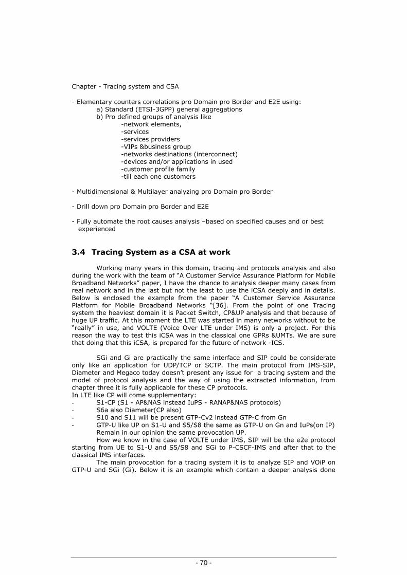
Chapter - Tracing system and CSA
- 70 -
- Elementary counters correlations pro Domain pro Border and E2E using: a) Standard (ETSI-3GPP) general aggregations b) Pro defined groups of analysis like -network elements, -services
-services providers -VIPs &business group -networks destinations (interconnect)
-devices and/or applications in used -customer profile family -till each one customers
- Multidimensional & Multilayer analyzing pro Domain pro Border - Drill down pro Domain pro Border and E2E - Fully automate the root causes analysis –based on specified causes and or best experienced
3.4 Tracing System as a CSA at work
Working many years in this domain, tracing and protocols analysis and also
during the work with the team of “A Customer Service Assurance Platform for Mobile Broadband Networks” paper, I have the chance to analysis deeper many cases from real network and in the last but not the least to use the iCSA deeply and in details. Below is enclosed the example from the paper “A Customer Service Assurance Platform for Mobile Broadband Networks “[36]. From the point of one Tracing system the heaviest domain it is Packet Switch, CP&UP analysis and that because of huge UP traffic. At this moment the LTE was started in many networks without to be
“really” in use, and VOLTE (Voice Over LTE under IMS) is only a project. For this reason the way to test this iCSA was in the classical one GPRs &UMTs. We are sure that doing that this iCSA, is prepared for the future of network -ICS.
SGi and Gi are practically the same interface and SIP could be considerate
only like an application for UDP/TCP or SCTP. The main protocol from IMS-SIP, Diameter and Megaco today doesn’t present any issue for a tracing system and the
model of protocol analysis and the way of using the extracted information, from chapter three it is fully applicable for these CP protocols. In LTE like CP will come supplementary: - S1-CP (S1 - AP&NAS instead IuPS - RANAP&NAS protocols) - S6a also Diameter(CP also) - S10 and S11 will be present GTP-Cv2 instead GTP-C from Gn
- GTP-U like UP on S1-U and S5/S8 the same as GTP-U on Gn and IuPs(on IP) Remain in our opinion the same provocation UP. How we know in the case of VOLTE under IMS, SIP will be the e2e protocol
starting from UE to S1-U and S5/S8 and SGi to P-CSCF-IMS and after that to the classical IMS interfaces.
The main provocation for a tracing system it is to analyze SIP and VOiP on GTP-U and SGi (Gi). Below it is an example which contain a deeper analysis done

Tracing System as a CSA at work
- 71 -
also on existing GTP-U and Gi(SGi) interfaces from GPRS-UMTS packet core( see also chapter 4 related also to [37])
As an evidence of the goals achievable with iCSA, we present experimental results from two measurements campaigns in a real mobile broadband network.
In the first example, we explain how to disclose possible network problems by properly analyzing Mobility and Session Management metrics.
In particular, we monitor a set of views of different kinds of metrics, while forcing a part of the network (only used for tests) to work in a shortage of
resources.
In the second example, we describe how to understand the performance experienced by the users and the possible causes of limitation through the analysis of metrics extracted from the IP and TCP headers. In this case, we analyze the data traffic flowing through the operational part of the network, and results are derived only from TCP/IP headers, without any content analysis, and having anonymized all user addresses.
a) Mobility and Session Management: a multi-dimensional analysis
This section shows how Mobility and Session Management metrics may be analyzed and what are in practice the views that are jointly analyzed presented for understanding where possible problems originate. In order to achieve this goal, we consider the trend of key measurements focusing on Mobility and Session
Management procedures [58]. In this experiment, traffic and configuration of the network have been purposely tuned to emphasize the aspects hereafter described.
The visibility on Session and Mobility Management it was obtained, thanks to
the distributed nature of iCSA, probing the Gb and Iu-PS interfaces -similar results could be obtained capturing at the S1 interface of a Long Term Evolution (LTE) network. In order to track the most important events related to the interaction
between users and network, xDRs have been generated monitoring the following procedures:
- GPRS Attach/Detach (explicit or implicit by inactivity timeout); - PDP Context Activation/Modification/Deactivation; - Routing Area Update.
A multi-dimensional representation was achieved with the following splitting mechanisms and related views:
- device view based on proper parsing of IMEI; - customer view based on the analysis of anonymized user identifiers,
typically used to assess the quality of key corporate accounts; - location view based on Routing Areas and Service Areas [59];
- service view based on APN.
Figure 3.5 Time behavior of Mobility Management and Session Management procedures:
a) at Iu-PS;
b) b) at Gn

Chapter - Tracing system and CSA
- 72 -

Tracing System as a CSA at work
- 73 -
Figure3.5.a illustrates the evolution over time of Session and Mobility procedures
that failed. Measurements are made at Iu-PS. As shown in the figure, the percentage of PDP context activation failures is rapidly increasing in a short period of time (from 00:01 to 00:16) and suddenly steps-back to normal values (from 00:16 to 01:31). The iCSA platform makes it possible to go much deeper and see:
1- The failure is not polarized by any specific location, customer groups and device types.
2- When splitting over different APNs considered in the traffic being analyzed, one of them (the one used for the tests) exhibits a spike in the PDP context failure.
3- When intersecting this specific APN with the information regarding the
session management causes (e.g., key session management information included in protocol transaction that identifies the reason of a failure), only one appears as causing most of the failures in the observed period: Activation Rejected by GGSN.
4- A view on the measures made at Gn interface (between SGSN and GGSN)
for the Gn PDP activation procedure highlights a similar trend seen on the Iu-Ps (see Figure3.5.b).
This experiment shows that the multi-dimensional view allows identifying the worst performing elements per different dimensions or the possible cooperation of different aspects to determine potential problems (e.g., device and APN). This enables the possibility of tracking potential issues - resulting in a loss of revenues
and low customer experience - which cannot be addressed by analyzing aggregated counters.
This is one of the key added values of iCSA. In this light, for instance, the identification of users highly impacted by a failure, while accessing the service, could drive quickly and easily to the most suitable operation needed to recover the issue: reconfiguration of terminal parameters to access a certain APN, tuning of the capacity on a per APN basis, etc.
b) Multi-Layer Root Cause Analysis of TCP Connections
TCP connections experience a number of performance issues when using
wireless networks. The novel Multi-Layer Root Cause Analysis (MRCA) of TCP connections implemented in the iCSA framework allows to infer the performance of the TCP connections and to determine the causes that limit their throughput (also
called root causes). The causes of throughput limitation can be grouped into three main categories:
i) application or user behavior;
ii) TCP stack configuration;
iii) network performance.

Chapter - Tracing system and CSA
- 74 -
The MRCA is aimed to identify the network-related limitations (the most important for the network operator), automatically in some cases, or carefully observing the results in other cases. This approach improves and integrates different techniques proposed in the literature - [47], [48] - and it is based on a number of xDRs calculated for three different points of view: aggregate, connection
and host. In the following, we report the results of the MRCA on the mobile broadband network before cited.
Aggregate: Figure 3.6(a) shows a summary of the results. The order of the retransmissions is 2%, acceptable for a cellular network [48]. The impact of these retransmissions on the performance of the users will be analyzed below.
Additionally, really surprising is the high number of connections having packets with the TCP-reset-flag set. Grouping the connections by xDR fields (retransmissions, reordering, number of packets, etc.), we identify three main causes:
(i) mobile stations trying to open TCP connections towards closed ports (mostly due to malware and unwanted traffic);
(ii) mobile stations experiencing bad network conditions, resulting in reordering and retransmissions of packets (the RST packets were sent after receiving unexpected packets);
(iii) mobile stations using a non-standard TCP implementation (the TCP RST packets were sent after receiving the TCP FIN packet). Generally, we could verify that those events were not impacting the throughput of the users.
Connection: this analysis reveals a number of TCP connections whose performance is not dominated by the application. Such connections are identified thanks to the methodology proposed in [48]. In particular, we use this methodology to divide the parts of the connections for which the application does not stress the network enough, from those for which the application always sends large-sized packets at a high rate. However, due to the time-varying conditions of the cellular channel, this methodology does not allow to identify the root cause, we can only exclude the
causes related to the application. The reasons are reported in the host analysis.
Host: thanks to the connection analysis, we could identify the set of connections whose performance is not limited by the application. In the following, we show the results of the host analysis of two mobile stations whose connections are in this set. Figure 3.6 (b) and Figure 3.6(c) illustrate the time behavior of the throughput,
retransmission ratio (also called retransmission score: the percentage of retransmitted packets), round trip time (RTT), and number of parallel connections of these mobile stations.
The first user (Figure 3.6.b) downloads about 20 MB from a Web server on a single connection, and at the same time, it opens a few other connections, transferring a small amount of bytes. Comparing the time behavior of throughput
and retransmission score, we see how this last parameter influences the throughput: for most of the samples, when the throughput decreases, the retransmissions increase.

Tracing System as a CSA at work
- 75 -
However, if we only look at the retransmission score, we can see that it is generally quite low, with a few spikes. This explains why the connection analysis did
not identify the root cause of the performance: the retransmission score averaged over the entire period is not high enough to be identified as the limiting cause. Comparing the other two plots, we can observe the effect of the buffering (in the mobile network and in the TCP stack): when more than two connections are active, the RTT increases.
The results for the second user are reported in Figure 3.6(c). For this mobile
station we observe a different behavior:
(i) the throughput is higher, reaching values up to 2.5 Mbps; (ii) the number of retransmissions is also higher, and they do not correlate with
the throughput; (iii) the RTT is very high and reaches a few seconds. Basically, this user is able to reach the maximum throughput allowed to him by the network, but the buffering is playing a big role, and the RTT increases, which may cause problems to some applications.
Finally, we can state that the throughput of the connections of these users is limited by the network, and that the multi-layer analysis allowed to easily identifying this limitation.
The root cause analysis of TCP connections permitted to spot some issues that affect the experience of the users. While for some of these issues (e.g., a high number of retransmissions in the network) it is possible to set up an alarm that
automatically alerts the operator when the aggregated counter reaches a certain threshold, some other steps of the analysis (e.g., the host analysis) still require the results’ observation by an expert. We are currently working towards the identification of other xDRs (e.g., the throughput correlation coefficient and retransmission score time series) that allow the automatic detection of these and other issues.
Figure 3.6 - Results of the Multi-Layer Root Cause Analysis of TCP connections a) Aggregate analysis
Connections analyzed 159445
Packets analyzed 5379640
Connections with retransmitted packets in either direction 36608 (23%)
Connections with 1 Byte retransmitted in either direction 17389 (11%)
Connections with reset packets in either direction 47851 (30%)
Reordered packets 4327
Out of sequence packets 13085
Packets retransmitted 100706 (2%)
Packets retransmitted for timeout in uplink 36465
Packets retransmitted for fast retransmit in uplink 3937

Chapter - Tracing system and CSA
- 76 -
b) Below enclosed host analysis for first user and graphical representations of : Throughput-Round Trip Time-Retransmission Score and - Number of Connection

Tracing System as a CSA at work
- 77 -

Chapter - Tracing system and CSA
- 78 -
c) Below enclosed host analysis for first user and graphical representations for : Throughput Round-Trip Time Retransmission-Score and-Number of Connection

Tracing System as a CSA at work
- 79 -

Chapter - Tracing system and CSA
- 80 -
Having the right implementation of this kind of tool, based on levels structure and families branches, starting from reports with alarming in real time till correlated messages traces, with the right navigations and linking between different levels and categories, including the automatically identifications of the fault causes, even limited ( based on standardization and including on demand the best experience of
each telecom operator); this kind of tool could be named like - one for multiuser groups including there all family of them, experienced ,not experienced, with and without necessary telecom protocol knowledge.

Chapter–Tracing Systems’ Protocols-Interfaces optimizations Monitoring Points
- 81 -
4 Chapter–Tracing Systems’ Protocols-Interfaces optimizations
How we have already mentioned in the case of systems tracing based on our
preferred solution (based on distributed probes and central data base) we have identified few possible issues:
a) Assure of monitoring points in side of the Network – see § 4.1 b) Deciphering of protocol interfaces (like Iub, Gb, NAS-S1-CP) – see § 4.2 c) Permanently traffic increases of UP and CP (dramatically increasing in the
case of IP-CAN–Broad Band Network) will present a way of optimization – see § 4.3, [36], [37] d) Inter-protocols correlations for the protocols and operations without permanent user identifiers [38], [39] - see § 4.4.
Below are presented few ways and few proposals of optimizations.
4.1 Monitoring Points
The right implementations of a tracing system need access on the network interfaces which has to be under monitoring. For this reason to assure monitoring points of network interfaces is very important (Figure 4.1).
The monitoring points has to assure a copy one to one of the interfaces and protocols stacks of the networks, without intruding or influencing the good functionality and security of the network. In the last time - because of telecom evolutions - the most used equipments to assure these requested monitoring points are (Figure 4.1):
a) Splitters –optical splitters split the signal with a specified splitting ratio,
b) The TAP (Test Access Port). To analyze high-speed networks in half or full
duplex mode, network TAPs provide permanent access ports throughout the network, to enable monitoring and analysis without interrupting transmission. Few companies which are producing this kind of equipments are: NetOptics,
Gigamon, VSS Monitoring. The splitters are presented in the network like passive components; we have to take care on splitting ratio to avoid any impact on the network.

Chapter–Tracing Systems’ Protocols-Interfaces optimizations
- 82 -
Figure 4.1 Monitoring Points
P-CSCF
AF
Switch
Monitoring Points
Analysier/Probe
TAP/Splitter
In most cases the TAP is an active network component; if it is used in–line
(here is this situation) playing a very important role to the right configuration of it, to keep the quality of the network and to avoid as much possible the network outage because of TAP. Other possibility to have the network under monitoring it is to use a mirroring port, from the switch or router, for the traffic passed within this
one - Figure 4.2. In the most of the cases this solution could be used only temporary, on demand, because of creating other issues like:
-security issue
-bad quality of tracing /repetition of messages in case of switch redundancy -analyzer/probe under not necessary load (double messages, could be send also other traffic than signaling) -not optimal use of resources - in the case of switch and probe
Figure 4.2 Mirroring Port
P-CSCF
AF
Switch
Analysier/Probe
Until now the most used solution is with splitter and TAPs, which practically
creates a lot of inconveniences: a) Re-cabling and a lot intermediary mechanical connection could conduct to
degradations of existing links quality b) Supplementary operations, in the case of tap in-line, to assure the right
implementation (configurations, tests of functionality, re-measurements of
network quality) c) HW or SW-Outages of and TAP in-line elements could create an outage in
the network or supplementary volume of work on rebuild the topology and the entire network functionality

Deciphering of protocol interfaces
- 83 -
d) Rebuild and updated of network data base topologies e) Supplementary know how on the TAP are necessary
In our opinion the best solution is to implement the Monitoring Points like
Monitoring Ports on the delivered telecom network. This has to be a standard for each vendor. This kind of implementation creates following advantages:
a) Easy implementation of the externals tracing system even later on one network which is from along time in service
b) Simplify of the Network Topologies
c) Maintenance of entire Tracing system without any service affecting in the telecom network
d) Data based of network topologies could be independently from the Tracing system
e) Safety mechanical connection of the networks links –no intermediary connections
Figure 4.3 Monitoring Port
P-CSCF
AF
Switch
Monitoring Ports
Analysier/Probe
For the Tracing systems users is not important how the vendors are realizing this requirement relating to monitoring port so long the upper advantages are reached and the below requirements will be respected: - Monitoring ports for CP, UP will remain in service even the network element is overloaded,
- Working on the monitoring ports will not affect the network functionality,
- The monitoring ports will provide the one to one information from the network interfaces, - No data lost, no bad quality or delay in delivery indifferent from the type or volume of traffic CP, UP.
4.2 Deciphering of protocol interfaces
For the tracing systems, introductions of different encryptions methods on
the interfaces and protocols represent supplementary effort on their implementations and on their resources usages. In practice we have observed that the implemented security method (the most implemented being IPSec) offer a way
to trace the same interface on the trusted area, after the security gateway. For us this is a way of improvements or the preferred solution, to place the monitoring
points of the related interfaces in the trusted area avoiding so extra working for

Chapter–Tracing Systems’ Protocols-Interfaces optimizations
- 84 -
deciphering. This way should be used where it is possible, where the implementations offer this opportunity.
In the case of E2E implementation, has to be used the de-ciphering if doesn’t split the interfaces on trusted and un-trusted zone/area. A good example is the de-ciphering of control messages over the Gb (the same applies to the Iub interface). To give to all probes in the network the possibility to decode these messages, it is necessary to dispatch deciphering keys both from the MAP-Gr interface or Gn interface for inter-SGSN mobility. Similarly, deciphering of Non-
Access Stratum messages at the S1 interface requires retrieving keys from the S6a
interface and S10 interface for inter-MME mobility [36]. Below is info about NAS-Encryption algorithm.
The 3GPP specifications - “Non-Access-Stratum (NAS) protocol for Evolved Packet System (EPS)” 3GPP TS 24.301 - foresee basically those three options for encryption of NAS messages on S1 interface:
- EEA0: Null ciphering algorithm does NOT require to retrieve keys from S6a and apply them to S1-AP to make the de-ciphering, that is indeed requested
in next two years - 128-EEA1 is a stream cipher based on another stream cipher, named
SNOWS 3G. EEA1 is an inheritance from UTMS and was introduced as 3GPP standard on 2006.
- 128-EEA2 is a stream cipher based on the block cipher AES algorithm used in its CTR (CounTeR mode) mode.
The deciphering could be done using two method topologies: 1) Standalone –directly on S1-Probe 2) Keys management on a central system as in Figure 4.4 1) Standalone Method
S1-NAS deciphering could be done on the probe level; for this reason is necessary to have (Figure 4.7): a) S6a monitored in the same probe as S1 (Control-Plane) interfaces b) S6a on different probes and transmitting these keys between HSS probes and each S1 probes. 2) Keys management on a central system
But the probes could have problem because of limited resources, so we
could use a keys management on a central system- see Figure 4.4. The operations flow in this case could be as in Figure 4.4:
0) Keys delivering or capturing on DB- Data Base Server 1) Capturing NAS messages on the S1 probe
2) Keys requests (from the probe) if the keys are not presented on the probe (based on the implementations from point a) or b) )
3) Keys Requests to the DB Servers 4) DB-Keys response 5) Keys response to the probes
6) Deciphering of NAS messages with the help of the keys The same methods could be used in the case of S10 interface. How we could
see in Figure 4.4 we have mentioned that the Keys are inserted in a RAM database,
because we considered a low latency of insertion and answering on the keys.

Tracing Packet-Core for CP and UP traffic
- 85 -
A combination of both methods could optimize the implementations from resource hardware and software point of view in the same time offering on demand
a partially redundancy of the system.
Figure 4.4 S1-NAS deciphering
S1Probe
TAPS
Monitoring Port
LAN-WAN
LAN-WAN
MME-LTE
DBServer&Keys alredyin RAM-DB received fromS6a Probes
UE/SIP
NAS-Mesages
1-NAS-Mesages
2-Keys request
3-Keys request
S6aProbe
0-Xdrs&Keys sendto servers
4-Keys
response
5-Keys response
6-In S1-ProbeNAS-MesagesDeciphered withhelp of the Keys
Switch
4.3 Tracing Packet-Core for CP and UP traffic [37]
In the last two decades there were major changes on fix and mobile
networks. The number of mobile devices grows rapidly, having a lot of resources for
applications, being always-on and always-connected. The applications are no longer isolated, entities exchanging information with the user interfaces entities able to establish a peer-to-peer connection using the Internet Protocol (IP) and enabling resource sharing. Now, we assist to the rapid convergence of fixed and mobile networks.
In the mid-1980s, first generation of mobile networks (1G) was introduced. They transmit only analogue voice information. In the 1990’s second generation
(2G) added data services (fax and short messages) and some supplementary services (fraud prevention and data encryption) for the users. The 3G systems or IMT-2000 (International Mobile Communications) means a set of compatible standards to be used worldwide, for mobile applications, which support packet switched (PS) and circuit switched (CS) data transmission and offer high data rates and high spectrum efficiency. IMT-2000 proposed as a successor for GSM (Global
System for Mobile communications) the UMTS (Universal Mobile

Chapter–Tracing Systems’ Protocols-Interfaces optimizations
- 86 -
Telecommunications System) that introduced a new radio access network UTRAN (UMTS Terrestrial Radio Access Network). The GPRS (General Packet Radio Service)
was the most important step to UMTS that introduced PS into the GSM CN (Core Network) and allowed direct access to packet data networks (PDNs). The first step of migration from circuit switches (CS) to packet switches (PS) in mobile networks was done with implementation of Release4 networks. In the Release5 was introduced the IMS (IP Multimedia Subsystem), formerly named All-IP, which realized a convergence of telephony world (for fixed or mobile users) and
internet world – see Figure. 1.1.
IMS is the most suitable to meet expectations for service quality, reliability and availability when moving from existing CS telephony services to IP-based LTE (Long Term Evolution) services (the greatest differences between LTE and UMTS lie in the air interface, UMTS is a Wideband CDMA-based system, while LTE is a scalable OFDMA system). IMS is able to serve simultaneously broadband wired and LTE wireless networks opening the path to service convergence. The new RAN (Radio Access Network) and interface has horizontal and
vertical layers. The RAN requirements are addressed in the horizontal radio network layer across different types of control plane (CP) and user plane (UP). CP is controlling a link or a connection and UPs are used to transparently transmit user data from the higher layers. CP and UP are managed separately. Standard transmission issues, which are independent of RAN requirements, are applied in the horizontal transport network layer. For the next future mobile
networks the GPRS-UMTS/EPC Packet Core (PaCo) networks will be use as access parts of IP networks to the IMS core.
The increasing of PS role means a necessity of finding the methods for real and deeper verification of present and future telecom networks functionality. To be able to verify the functionality of PaCo telecom systems, a powerful tracing system is necessary.
A complete and very good analysis involves Control-Plane (CP) traffic and
User-Plan (UP) traffic tracing. Because UP traffic is booming now and the resources for a tracing tool are limited and most of them are crashing under the task to trace 100% UP traffic, it is necessary to find new methods of tracing of CP and UP traffic. For this reason our new method of tracing for CP traffic and UP traffic will start here from GPRS-UMTS.
Increase of bit rate: bit rate of links probed close to key network nodes is continuously growing. Typical GGSN (Gateway GPRS Support Node) capacity is
around several Gbps and it is expected to increase suddenly during the upcoming years, especially with the transition to Evolved Packet Systems . iCSA supports specialized packet-capturing and preprocessing hardware and software designed to exploit modern multi-core CPUs [36].
From the practice perspective we can find cases where the traffic of the network could evaluate very rapidly that the tracer components, probes, will be not
able to process the real traffic. The resources of actual tracing tools for CP and UP traffic are limited and most of them are crashing under the task of tracing 100% User-Plan traffic. This paper proposes a new tracing system for UP&CP traffic of Packet Core networks, like GPRS-UMTS, EPC networks, in order to verify their functionality.

Tracing Packet-Core for CP and UP traffic
- 87 -
4.3.1 IP-CAN interfaces
The main IP-CANs for Mobile networks are:
a) GPRS-UMTS (General Packet Radio Service- Universal Mobile Telecommunications System)
b) EPS- LTE (Enhanced Packet-Switched Core Network - Long Term Evolution) - EPC enhanced Packet-Core MME/S-GW&PGW having the role of SGSN/GGSN
together
a) GPRS-UMTS Interfaces
Within §1.1.1-, we have introduced already some typical GPRS interfaces
related to Release 99. For this release, ATM (Asynchronous Transfer Mode) has played a very important role. In ATM network, composed of ATM nodes and links, the user data is organized and transmitted in each link with a stream of ATM cells. AALs (ATM Adaptation Layers) are defined to enable different types of services with corresponding traffic behaviour; two of these are applied in UTRAN: Iu–CS (Iur, Iub: AAL–2) and Iu–PS (Iur, Iub: AAL–5). Iur stands for radio network sublayer application part (RNSAP) and Iub stands for node B application part (NBAP), over
which UTRAN transfers specific signalling and control messages. Today in many networks Iu-PS is implemented over ATM, but in the next step it will be over
IP/SCTP (Stream Control Transmission Protocol). This protocol layer allows the transmission of signalling protocols over IP networks. Its tasks are comparable with MTP3b (Message Transfer Part level 3-broadband).
Gi is a GPRS interface located between the GGSN (Gateway GPRS-Support-
Node) and the external PDN (Public Data Network). Gp appears when the GGSN (Gateway GPRS Support Node) and the SGSN (Serving GPRS Support Node) are located in different networks; they may be interconnected via the Gp interface. Gn is an interface between GSN (GPRS Support Nodes) within the same PLMN in a GPRS network. Gn interface is still present but in the future it will replaced during the evolution on EPS (Evolved Packet Sytem).
With respect of all differences, in the case of 3G-PS direct Tunnel
implementation we could force a comparison between Gn-Cp(GTP-C) and S10/S11(GTP-Cv2) from LTE and S1-U(GTP-U), like UP with IuPs-UP/IP in the case of UMTS-PS direct Tunnel-enabled architecture; which allows a tunnel to run straight
from an RNC (Radio Network Controller) or I-HSPA (Internet High-Speed Packet Access) - enabled base station to the GGSN(S1-U from eNB to S-GW&P-GW in LTE). In the most of LTE real implementations S-GW( Serving Gateway ) and P-GW(PDN Gateway) are collocated in the same hardware and presented like U-GW (Universal
Gateway) and in this case we could force this interfaces/protocols comparison 3G-PS with 4G even much better; applying this new method of tracing mentioned below also in the case of LTE S1/S1-U(IuPs-CP/IuPs-UP) and SGi(Gi)(see Figure 1.9)
Gb is not mentioned here, only Iu-Ps-3G interfaces. Is mentioned here only Iu-Ps-3G interfaces, because of big speed and big
traffic contribution. For these reasons, in the new method of tracing only IuPs and
Gi interfaces will be involved (for others it can be extended on demand). Fig.4.5 shows not only the most important interfaces from PaCo but also the next step of IuPs evolution, from ATM to IP. The layers representation is not done to represent 100% correspondence: this is valid for upper layers APP/TCP-UDP/IP.

Chapter–Tracing Systems’ Protocols-Interfaces optimizations
- 88 -
In Figure 4.5 are shown the PaCo interfaces and different abbreviations: PaCo (Packet Core), RANAP (Radio Access Network-Application Part), LLC (Logical
Link Control), GTP–U/C (GPRS Tunnelling Protocol - User/Control), SCCP (Signalling Connection Control Part), SGSN (Serving GPRS Support Node), SNAP (SubNetwork Access Protocol), E2E (End To End), UDP (User Datagram Protocol), AAL2-5 (ATM Adaptation Layer type 2-5), APP (Application), M3UA (MTP3 User Adaptation layer), SSCOP (Service-Specific Connection-Oriented Protocol), SSCF/NNI (Service-Specific Coordination Function / Network Node Interface), Iu–interface between RNC (Radio
Network Controller) and CN- [14]
Figure 4.5 The Packet Switched Core Network (PS CN) or PaCo interfaces
a)
SGSN GGSN
IU_PS-UP
Gn-CPIU_PS-CP
GiGn-UPInternet
RNCs
b) c) d) e)
f)
Gi
IP TCP/UDP Application
L1
L2
IP UDP
GTP - U IP
TCP/UDP Application
L1
L2
Gn - UP
Gn - CP
IP UDP
GTP - C
L1
L2 IP
UDP GTP - U
IP TCP/UDP Application
L1
L2
Iu_Ps - UP_IP
IP
SCTP
M3UA SSCP(CO)
RANAP
L2 L1
IuPs - CP_IP

Tracing Packet-Core for CP and UP traffic
- 89 -
b) LTE-interfaces For these interfaces, introduced in § 1.1.4, see Figure 1.9 Evolved Packet
Systems.
4.3.2 Tracer using Static and Dynamic Filters
The PS–UP–traffic is booming in the last years and the trend remains the
same because of Mobile Internet. For this reason we need to re-think the solutions of tracing systems. Most of the analyzers do not have the capacity and resources under UP traffic from Iu–PS/Gn/Gi(S1-U,S5-S8,SGi) (that means traffic bigger than
10 Gbps). Because of limited capacity, to use the tracing system, it must reduce the input UP traffic to the analyzers. Now that is possible for: - IuPs under ATM, where it can disable the VPI/VCIs (Virtual Path/Circuit Identifiers) for specified RNC, - Gi using IP ranges - but these are static filters without possibility to respect E2E
requested trace.
E2E means to be able to follow on demand UP traffic from Iu-Ps to Gi. We need dynamically filter systems. On the top of filters we can use UI (Users Identifiers) - i.e. IMSI (International Mobile Subscriber Identity); on the base, at low layers protocols, we can use other filters necessary to keep the system working and
able to trace the associated UP plane traffic.
With other words, we have to start from the normal identifiers like IMSI and we discover the appropriate identifiers present in UP via CP with possibility to trace the associated UP plane traffic E2E, keeping in the same time the system alive and its tracing functionality.
The trend of the interfaces is ETH/IP/All-IP (ETH-Ethernet). Most of the analyzers or probes are able to work there, with or without UP (or, we can say, with
1 or 0). Without UP, it is not acceptable. Also, it’s not a solution to look for 100% UP traffic, because the increasing traffic and because the probes/analyzers are not able to follow it (only with huge increasing of probes numbers). We don’t know vendors that have a solution of tracing system that are able to follow the daily increasing UP traffic (without increasing the number of hardware-probes-analyzers). For this reason we had to implement a new concept and solution like: dynamically filtering
at probe level, or before at TAP level (Test Access Port). To analyze high-speed networks in half or full duplex mode, network TAPs provide permanent access ports throughout the network, to enable monitoring and analysis without interrupting transmission.
After a short analysis, the best solution is dynamically filtering at probe level or transmitting (using the WLAN see Figure 4.2) the information where this is necessary and to build the appropriate filter on the TAP or other probes. The right
filter utilisation depends on the technical implementation; for example - the TAPs could introduce delay by applying the filter- later than UP activation. The method of dynamically filtering is based on the following idea-as described below: the operators has to use like filters few parameters available in CP traces (i.e users identifiers) and based on these - from CP traces will be captured the associated UP traffic identifiers, these identifiers will be available before having UP active.
These filters will be propagated to all monitored interfaces from PaCo and
they will be able to collect all other identifiers starting from CP and to filter the UP.

Chapter–Tracing Systems’ Protocols-Interfaces optimizations
- 90 -
Some parameters to be used in filters are: IMSI (International Mobile Subscriber Identifier), IMSI ranges, MSISDN (Mobile Station Integrated Services Digital
Network), RAC (Routing Area Codes), IP, APN (Access Point Names). These can be used in different logical associations (and, or). Using this type of filtering we can have 100% CP traffic under tracing and we can follow the UP trend, and it can check and analyze network quality, and it can solve on demand or proactive customer complains. This new type of filtering will work as follows. For example, filtering on IMSI
or IMSIs range (starting from CP) will be propagated in all others interfaces (IuPS,
Gn, Gp, Gi – see § 4.3.1 – GPRS-UMTS Interfaces) and before having UP already active, during of PDP (Packet Data Protocol) activation it can collect all others parameters from CP traces, necessary to filter UP. The others parameters could be: IPs, APNs, even RAC (Routing Area Codes) and with their help, RAC can work like in case of IMSI to have a deeper filtering system for UP traffic. With these parameters all CP traffic will remain under tracing/analyze and only that UP traffic which matches the filter. All others messages from UP that do not match our filtering
system will be discarded and the traffic analyzer can work without problem (because traffic under monitoring is smaller than analyzer traffic limits).
With this new concept of tracing, the following targets can be reached: i) network quality and maintenance on demand or proactive, that means revenue per customers, ii) the tracing system investments will be dramatically reduced, because stability
and functionality are preserved even the UP traffic is huge and it will work exactly when we need it, in peak hours and days, or even when the networks have problems, iii) the tracing system investment is not necessary proportional with the UP traffic increase, iv) flexibility of the new tracing system.
Figure 4.6 General tracer architecture-GPRS
WANWAN
InternetInternet
Servers-Data-Base->xDR-DB->Call/Events DataRecords-DB
Admin or Client
IuPs Gn GiSGSN
GGSN
TAP&Probe
TAP &Probe
TAP&Probe

Tracing Packet-Core for CP and UP traffic
- 91 -
Figure 4.7 Traffic UP_PS after static and dynamic filters
UP_PS _Filters to reduce traffic for Analysor that to be able to monitoring when the traffic is upperAnalysor specified limits
Traffic UP_PS after using Static_Filter
Traffic UP_PS after using Dynamic Filter
Traffic UP_PS after using Dynamic Filter added toTraffic UP_PS after using Static_Filteris under (or equal)Analysor specified limits
Copy of traffic for tracingavailable 1:1
Analysor specifiedlimits
After Filtering :
UP_PS _Filters will be used to reduce traffic for analyzer such that it will be able to monitor the traffic when this is over the specified upper limit of the analyzer. The Figure-4.7 shows a combination of the already defined concept of “dynamic-filter”. The dynamic filtering starts with users identifiers like IMSI or others external parameters, it checks and finds in the CP the parameters necessary to be applied
such as filters, to select and collect the associated UP.
UP_PS_Filters will be used to reduce traffic to analyzer in order to keep the stability of the tracing system and even to trace and monitor when the traffic is upper than analyzer specified limits. There is present also the Static-Filter (based for example on IP ranges, APNs, which are in use).
Static-filter reduces the UP traffic under analyzer limit without collecting
information for it from CP. With these filters we can have permanently under monitoring a part of UP traffic, but under specified limits of the analyzer. A dynamic-filter is used on demand to check the users with problems, or the problems from the networks for which the UP traffic is not already analyzed with static filters. After using dynamic-filter added to static-filter, UP_PS traffic is under or equal analyzer specified limits.
4.3.3 New Method of Tracing
How it was already mentioned, today Iu-Ps is implemented over ATM in many networks, but in the next step it will be over IP. Gn will still be present, but in
the future it will disappear because of integrated SGSN together with GGSN functionality or using direct Tunnel-enabled architecture, which allows a tunnel to run straight from an RNC to the GGSN. Gb is not mentioned here, only Iu-Ps-3G
interfaces because of big speed and big traffic contribution. For these reasons, in

Chapter–Tracing Systems’ Protocols-Interfaces optimizations
- 92 -
the new method of tracing only IuPs and Gi will be involved, for other this can be extended on demand - for example for Gp.
Let’s take one example regarding IMSI user identifier. The dynamic filter system has to start using users identifiers (like IMSIs) to
discover in CP the right parameters and to be applied like filter to IP low layer protocol (see Fig. 4.8). This filter is necessary to extract the associated UP traffic; also with help of this filter we will be able to keep the tracing system functionality (maintaining traffic under the specified limits).
The filters are necessary to be applied on the bottom low layers protocol
because the messages that do not match this filter must be discarded from the beginning without consuming resources of tracing system. The logical chain for Gi interfaces is: IMSI is present in RANAP-PDP_context request IP_PDP_Context (for this IMSI) will be present in RANAP-PDP_context response
(in IU-PS) - see Fig. 4.5 this IP_PDP_Context is present in Gi like source IP in UL
(uplink) messages and like destination in DL messages - see Fig. 4.8. For Gi the filter is complete: IMSI IP (IP_PDP_Context from CP-IU_PS or today also Gn).
Let’s explain how the filter for Gi can be extracted or propagated (see Figure
4.6 and Figure4.7). The tracer will be connected to trace the total traffic from (with help from TAP) CP of Iu_Ps (or Gn). The associated Data-Traffic from Gi will be
available applying the filters based on discovered IP (IP_PDP_context); in the case of tracing of many interfaces in the same analyzer (IuPs&Gi or Gn&Gi) or in case of the distributed probes / analyzers-these to be prepared to exchange this information via WAN (depends of Tracer architecture and implementation see Figure 4.6).
The logical chain for Iu_PS is: IMSI is present in RANAP PDP context request
IP_PDP_Context (for this IMSI) will be present in RANAP PDP_context response
GTP-U-TID (TID-tunnel identifier is also present in RAB assignment) RNC_IP_TLA
(RAB assignment – TLA = TransportLayerAddress) in each message from UP at low layer IP (Transport Layer) RNC-IP-TLA GTP-U-TID IP (IP_PDP_Context is
present like source IP in UL (uplink messages) and like destination in DL messages (see Fig. 4.9).
Filtering on IMSI or IMSIs range (starting from CP): this filter will be propagated in all others interfaces (IuPS, Gn, Gp, Gi) and before having UP already active, during of PDP (Packet Data Protocol) activation, it can collect
IPs_PDP_Context: IP_PDP_Context can be used directly like the filter in case of Gi (see Figure 4.8)
CP Call Flow and Method to discover the Filter parameters necessary to select the associated data-traffic to Gi (starting from established Gi/TCP connection) are: 1 - IuPs RANAP PDP_Context_Request -IMSI is present in this message
2 - Gn-GTP-C PDP_Context_Request -IMSI is present in this message 3 - Gn-GTP-C PDP_Context_Response -IP_PDP_context is present in this message 4 - IuPs RANAP PDP_Context_Response -IP_PDP_context is present in this message
So, as long as IP_PDP_context is present, it will be used as filter in Gi interface to filter the associated data for Up-Link-this-IP-source-messages and for
Down-Link-IP-destination-messages.
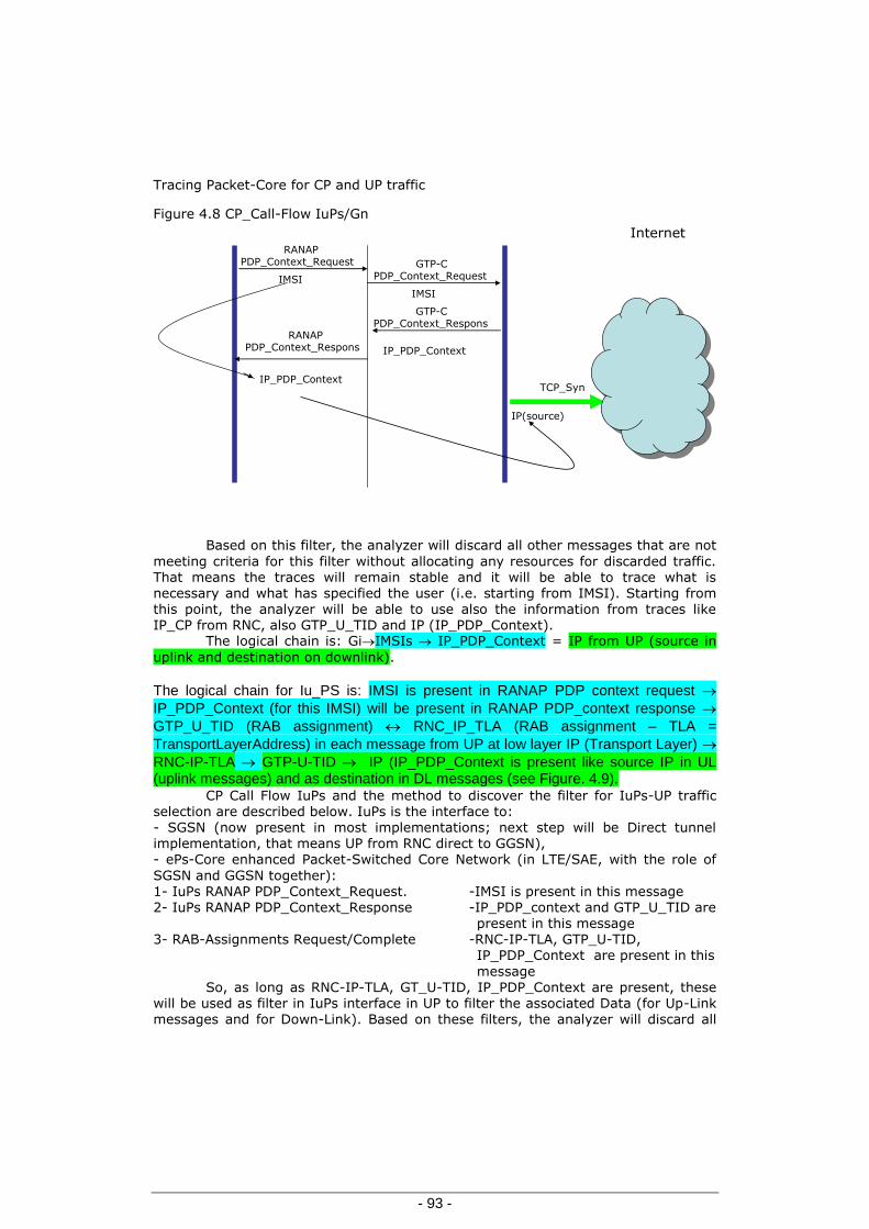
Tracing Packet-Core for CP and UP traffic
- 93 -
Figure 4.8 CP_Call-Flow IuPs/Gn
InternetRANAP
PDP_Context_Request GTP-CPDP_Context_Request
RANAPPDP_Context_Respons
GTP-CPDP_Context_Respons
IMSI
IMSI
IP_PDP_Context
IP_PDP_Context
IP(source)
TCP_Syn
Based on this filter, the analyzer will discard all other messages that are not
meeting criteria for this filter without allocating any resources for discarded traffic. That means the traces will remain stable and it will be able to trace what is necessary and what has specified the user (i.e. starting from IMSI). Starting from this point, the analyzer will be able to use also the information from traces like IP_CP from RNC, also GTP_U_TID and IP (IP_PDP_Context).
The logical chain is: GiIMSIs IP_PDP_Context = IP from UP (source in
uplink and destination on downlink).
The logical chain for Iu_PS is: IMSI is present in RANAP PDP context request
IP_PDP_Context (for this IMSI) will be present in RANAP PDP_context response
GTP_U_TID (RAB assignment) RNC_IP_TLA (RAB assignment – TLA =
TransportLayerAddress) in each message from UP at low layer IP (Transport Layer)
RNC-IP-TLA GTP-U-TID IP (IP_PDP_Context is present like source IP in UL (uplink messages) and as destination in DL messages (see Figure. 4.9).
CP Call Flow IuPs and the method to discover the filter for IuPs-UP traffic selection are described below. IuPs is the interface to: - SGSN (now present in most implementations; next step will be Direct tunnel implementation, that means UP from RNC direct to GGSN), - ePs-Core enhanced Packet-Switched Core Network (in LTE/SAE, with the role of
SGSN and GGSN together): 1- IuPs RANAP PDP_Context_Request. -IMSI is present in this message 2- IuPs RANAP PDP_Context_Response -IP_PDP_context and GTP_U_TID are present in this message 3- RAB-Assignments Request/Complete -RNC-IP-TLA, GTP_U-TID, IP_PDP_Context are present in this
message So, as long as RNC-IP-TLA, GT_U-TID, IP_PDP_Context are present, these
will be used as filter in IuPs interface in UP to filter the associated Data (for Up-Link
messages and for Down-Link). Based on these filters, the analyzer will discard all

Chapter–Tracing Systems’ Protocols-Interfaces optimizations
- 94 -
other messages that do not meet criteria for these filters without allocating resources for discarded traffic. That means the traces will remain stable and it will
be able to trace what is necessary and what the user specified (starting i.e. from IMSI). Figure 4.9 CP_Call Flow IuPs.
RNCs
RANAP_PDP_Context_Request
RNC-IPs-sig, IMSI
GTP_U-TID, IP_PDP_Context
RNC-IP-TLA, GTP_U-TID, IP_PDP_Context
GTP_U
RAB-Assigment
RNC-IP-TLA, GTP_U-TID, IP_PDP_Context
Again the logical chain is: Iu_PS_CP traces: IMSIs IP_TLA GTP-U-TID
IP_PDP IP_UP (low layer) GTP_U_TID IP source / destination.
For information about protocols and LTE interfaces see § 1.1.4, Figure 1.9.
Evolved Packet Systems. The same concept of statically and dynamically filters could be easy used in
the case of LTE making the easy association between interfaces:
IuPs-Cp/RANAP-NAS S1-Cp/S1Ap-NAS
IuPS-UP/GTP-U S1-U/GTP-U
Gn,Gp/GTP-C S10-S11,S5-S8/GTP-Cv2
Gn,Gp/GTP-U S5-S8/GTP-U
Gi SGi
How we can see: - GTP-U and Gi-SGi are the same protocols - APN-concepts remain the same and the IP’s ranges associated could be used
for the - static filters
The Dynamic filter will work like before presented - starting from
permanents identifiers of the users (like IMSI) and/or other information from the network (LAC, RAC, TAI, C-RNTI, ECGI, for other LTE parameters see also § 1.1.6

Tracing method with intra and inter protocols correlation-of the protocols and operations without permanent subscribers identifiers
- 95 -
IMS Calls-Flow example, EXAMPLE.1 LTE , Figure 1.13 LTE Attach) and discovering the IPs of UE associated (for SIP and Media-VOIP in the case of IMS, and Internet-IP
for data) we can build the filters following on demand, the customer, groups of customers where were signalled new issues. For a tracer, or a protocol analyzer, intra-protocol and inter-protocol correlation offers the possibility to identify the traffic problems in telecom networks using an E2E trace. The existent PaCo networks will become IMS IP-CAN, so the new method, based on intelligent filtering, is a better solution, because the filters
used today are crashing under the task to trace all UP and CP traffic.
In our implementation, the total CP traffic and only the selected UP traffic remains under tracing analysis. All other messages from UP that don’t match our filtering system will be discarded starting from the beginning, without adding new resources to the analyzer, so the tracing can work without problem. In the case of PS network the filtering can be done on: IMSI, MSISDN, RAC, LAC, TAI, etc. This method can be applied also for VOIP starting from CP (SIP signalling) to filter only the UP (VOIP) associated. With this new concept, network quality, customer
satisfaction, tracing system stability, investment/cost in normal limit and the flexibility of a new tracing system can be reached. In the case of PS–GPRS-UMTS<E for the tracing systems based on xDRs implementation, the resource optimisations - xDRs building - for long durations of data session call is very important:
a) CP–xDRs to be build per operations and linked in the same session, based on the permanent user’s identifiers and temporary user identifiers and network identifiers b) UP–xDR’s building them on the transport protocols TCP/UDP and on the Applications levels.
4.4 Tracing method with intra and inter protocols
correlation-of the protocols and operations without permanent subscribers identifiers [38], [39]
Starting from Rel4 appears a separation of CP (Control Plane) and UP (User
Plane) management within the networks. MEGACO (Media Gateway Control) protocol plays an important role in the migration to the new releases or from
monolithic platform to a network with distributed components. MEGACO or H.248 is a protocol enabling a centralized Softswitch (or MGC) to control MGs between Voice
over Packet (VoP) networks and the traditional ones. To analyse much deeper the real implementations it is indicated to use tracing system with intra and inter protocols correlation. For this reason in the case of MEGACO-H.248 it is necessary to find the right method of correlation with all protocols involved.
4.4.1 MEGACO Protocol
MEGACO protocol was designed for the media gateways with distributed subcomponents required in the complex networks. IETF (Internet Engineering Task Force) specified in RFC.3015 later replaced by RFC.3525 and aligned with ITU-T specification H.248, which itself supplements the earlier H.245 gateway component of the H.323 videoconferencing standard [1, 2, 3]. MEGACO is used between a
media gateway (MG) and media gateway controller (MGC) to handle signaling and

Chapter–Tracing Systems’ Protocols-Interfaces optimizations
- 96 -
session management during a multimedia conference. The MGC and the MG share a master/slave relationship.
The connection model for protocol describes the main objects within a MGs as terminations and contexts that can be controlled by the MGC. A termination sources or sinks (either originates or terminates) one or more streams, and each termination holds information about the actual media streams. Different terminations are linked together by a context. A context describes the topology of terminations associated with it: for example, it includes parameters about mixing in
case the context contains more than two terminations.The set of terminations that
are not associated with other terminations are defined as being represented by a special type of context (namely, the null context).
The MEGACO protocol is used in the 3GPP-IMS Mn and Mp reference points [9]. The Mn interface is the control reference point between the MGCF (Media Gateway Control Function) and IMS-MGW (Media Gateway Function). The Mn interface controls the user plane between IP acces and IMS-MGW (Mb reference point). Also, it controls the user plane between CS (Circuit Switched) access (Nb and
TDM interfaces) and IMS-MGS. The Mn interface is based on H.248 and is equivalent to the usage (encoding, decoding, etc.) of the Mc interface specified to control the CS-MGW. The difference between these two interfaces is that Mn interface introduces new H.248 procedures for handling IP access end termination and also some additional procedures for CS end termination handling. The H.248 is primarily used to perform the following tasks: reserve and connect terminations, connect or
release echo canceller to terminations, connect or release tones and announcements to terminations, send/receive DTMF tones.Mp reference point: when MRFC (Multimedia Resource Function Controller) needs to control media streams (e.g. to create connections for conference media or to stop media in MRFP- Multimedia Resource Function Processor) it uses the Mp reference point. This reference point is fully compliant with H.248 standard.
The IMS services implentations required extensions of this protocol like in
the case of Iq interfaces specified late in the Release 10(see Figure 1.12). This interface is based on H248 extended version and is working between
ATCF(Access Transfer Control Function) and ATGW (Access Transfer Gateway)(ATCF&ATGW have a very important roll in SRVCC -Single Radio Voice Continuity within ICS - IMS Centralized Services, HO improvement)
MEGACO is as an open standard meaning that Telecom company and others
can now purchase their media gateways (MG/MGW) and gateway controllers (MGC/MGCF Media Gateway Control function)) from different vendors with lower cost. It also allows the addition of extra MG of a common type running under the same controller, instead of replacing low-capacity gateways by high-capacity specimens at the high prices.
A mobile network will have to interface to external services over a variety of
media, using formats that require conversion to enable effective communication. The MEGACO Protocol provides a framework for the operation of MG and specifies how they interact with a MGC for connection control. The basic concepts used to define the connection control are the terminations and contexts [3].
A termination acts as the source or the sink for one or more media streams or control streams, while a context is an association of a number of terminations. The context defines who sees or hears whom and also covers any mixing or
switching parameters that are required between different terminations. The number
of terminations per context is a characteristic of an individual media gateway. An

Tracing method with intra and inter protocols correlation-of the protocols and operations without permanent subscribers identifiers
- 97 -
MG that handles access and conversion for point-to-point links may be restricted to two terminations, whereas an MG for multipoint processes will normally have to
support at least three. A termination can either represent a physical entity, such as a trunk interface port or channel on that trunk, or an information flow, such as RTP. A termination has two main features: TerminationID, and Properties and descriptors.
TerminationID is an identifier issued by the MG, according to its own
scheme, when the termination is created and may be structured, for example, to
indicate channels within a trunk. The characteristics of a termination are given as properties that have an ID and a description. For the descriptors MEGACO provides two styles of expression: textual or binary-encoded. The textual format uses abbreviations of the field names based on SDP (System Description Protocol) rules, while the binary option uses concise tag values to express the Property_ID for local or remote descriptors accompanied by binary tag values in defined field sizes and format.
The Property_ID tag values are divided into specific groups according to the type of descriptor. The parameter values associated with these tags define the characteristics of the media streams sent or received by the media gateway. Some of the types of specific importance to 3G networks are general media and AAL2 and AAL5 (ATM Adaptation Layer) attributes.
The MGC controls its media gateways by means of the MEGACO commands:
they are used to manipulate the logical entities - terminations and contexts - described in the connection model. Each command can carry a number of parameters, called descriptors, consisting in a name and a list of items, some of which may have values. A command may also return descriptors as output [8].
4.4.2 Megaco Correlation Method The identification of problem: MEGACO doesn’t have identifiers related to
the public or private User_ID. For this reason to be able to correlate MEGACO traces with traces from other interfaces or protocols we should find the rule. First observation regarding missing of Users_ID must be completed with: MEGACO is based on TermIDs.
During our study we did a separation of the issues for MEGACO correlation
of IP, ATM and TDM (Time Division Multiplexing) media. Based on the specifications and of our practically observation using Wire-Shark Traces we clarified that the correlation of CP protocols with MECACO for media IP/ATM (or UP IP/ATM) is much easy. There are common identifiers used in the same time at level CP protocols (i.e. SIP/BICC/RANAP), MEGACO and UP Media, comparing with ISUP and GSM-A
protocol where the situation is different; no common protocol identifiers are available at traces level for these and MEGACO. This problem is very important to be solved for following networks type and topologies:
a) Release4 networks where it can see TMD technology, in access and networks interconnect with other operators
b) Interconnect under IMS of different networks like REL4 and ALL-IP, c) Interconnect of IMS with PLMN (Public Land Mobile Network) and PSTN
(Public Switched Telephone Network) on ISUP-TDM.

Chapter–Tracing Systems’ Protocols-Interfaces optimizations
- 98 -
Based on these considerations we have started from RFC.3525 where we have found the important information. Terminations are referenced by a TermID,
which is an arbitrary schema chosen by the MG. TermIDs of Physical_Terminations are provisioned in the MG. The TermIDs may be chosen to have structure. For instance, a TermID may consist of trunk group and a trunk within the group. At the beginning we have identified the problems:
- user identifiers are not presents in MEGACO Protocols,
- in MEGACO one important parameter on TDM is TerminationID,
- there are internal TerminationIDs (subject of provisioning) and external TerminationIDs present in MEGACO traces,
- we should identify the conversion rule of intern_TerminationIDs to extern_TerminationIDs.
For a human operator in Telco Network is very important to be able to find
the problems from the network. That became much easier using a Protocol Analyzer
(Trace) with possibility of E2E inter protocols and interface correlation starting from what is easy to know, problem of Network Users and in direct connection with Users –Identifiers (IMSI/MSISDN).
Correlation can be done starting from User_Identifiers (IMSI/MSIDN,
Calling, Called) (International Mobile Subscriber Identity/Mobile ISDN) to find the
traces related to BSSAP/ISUP (Base Station System Acces Point/ISDN User Part) and from some parameters from this traces. From these parameters we can find the internal TermIDs and finally, based on the rule of conversion, we can have then external TermIDs.
The logical chain is: User-IDs (IMSI, MSISDN-Calling, Called) BSSAP/ISUP-TDM-
Traces (Parameters) Parameters from these trace Int_TermIDs (conversion
rule) Ext-TermID (from MEGACO Traces) MEGACO Traces.
Information regarding ISUP and BSSAP (E1-TDM) correlation with MEGACO:
one problem is to find the TermIDs structure and the possibility to identify these using the information from trace A-BSSAP and ISUP. That depends from
implementation. The TermID structure has to follow the guidelines of H.248 and the structure is either relevant or irrelevant for MGC and MGW. When bearer type is
physical timeslot within TDM circuit, the TermID structure follows the Termination naming convention for TDM circuit bearer. It uses the ASN.1 (Abstract Syntax Notation.One) coding.
General Structure of TerminationID: {4 octets must be used for the TermID;
the following defines the general structure for the TermID; termination_type, 3 bits (000 Reserved, 001 Ephemeral termination)}: 010 TDM_terminations:
011 110 Reserved, 111-Reserved for ROOT_Termination_ID (=0xFFFFFFFF)
X: usage dependent on Termination_Type (*1)
MGC: S (*2)

Tracing method with intra and inter protocols correlation-of the protocols and operations without permanent subscribers identifiers
- 99 -
(*1) For Termination_Type is specified only TDM_terminations (other usage being unspecified), specified by: Termination naming convention for TDM_terminations:
(*2) MGC=PS (Packet switched), only 16 bits are used. MGC= S, that means to
correlate all we should extract from BSSAP (A interface) traces the information which can help us to identify the Internal_TermIDs provisioned inside of MGC/MGW and after conversion to find the External_TermIDs from MEGACO. (*3) For PCM (Pulse Code Modulation) system usage is unspecified. Uniquely identifies PCM interface in MGW. (*4) Individual: maximum of 32 individuals (timeslots) per PCM system (or maximum 24 individuals for a 24 channel system).
Let’s take a case for MOC (Mobile Originating Call) or MTC (Mobile Terminating Call) starting/ ending to one BSC (Base Station Controller). Like example we have used traces from Core Rel4 based on MGC&MGW Nokia.
From A interface are useful the parameters: {PCM-Trunk Number, Timeslot Used (CIC- Circuit Identification Code-like in trace), Time (because the TermIDs is used only at this moment), SPC (OPC or DPC) (Signaling Point Code; Originating
Point Code; Destination Point Code)}. Based on them we can identify the internals TermIDs (subject of
provisioning). With SPC (DPC or OPC), PCM-Trunk Number and TS (Time Slot) we can find in the MGC or MGW TermIDs (Internal) [10].
Example: OPC=701 PCM=11 TS=25 TermIDs (Internal) = 01346–025 meaning
that 01346 it is subject of provisioning and 025 is TS (CIC). Example of conversion Int_TermIDs Ext_TermIDs: TermIDs_Intern = 01346-025. TermIDs_Ext (from
MEGACO Trace) = 4000A859H. Using the rule from Terminations_Name ASN.1 documents we found the following association: 1) Conversion from TermIDs_Int in TermIDs_Ext
TTT(TermType) =010 TDM
PCM System
=000000000000
010101000010 01346
TS (CIC) = 11001
025
All Toghether:
=0100000000000000
1010100001011001 4000A859h
From ISUP traces we can use the parameters: SPC (OPC or DPC), CIC. Example:
SPC=11361, CIC=1562.
Termination type
(010 for TDM)
PCM system
(24 bits) (*3)
Individual
(5 bits) (*4)

Chapter–Tracing Systems’ Protocols-Interfaces optimizations
- 100 -
2) Conversion from TermIDs_Extern in TermIDs_Intern:
4000A859h (from HEX in BIN)
0100000000000000
10101000010 11001
010
= Term Type-
TDM (3bits)
000000000000 0010101000010
=1346-Channel System
(24bits)
11001 =25 TS (5bits)
3) CIC must be converted in binary and the last 5 bits give us the TS and other is PCM trunk number.With all this information (SPC, CIC=PCM trunk number and TS) we are able to find the Int_TermIDs from MGC/MGW. All others are identically like
for A interfaces. PCM trunk number (and TS) is subject of provisioning and the name
depends on implementations.
4.4.3 Network and traces For our study we have collected traces from an REL 4 network-Figure 4.10.
Figure 4.10 REL 4 Network
MGW MGW
MGC MGC
RNC
BSC
IuCs_UP
A
A-TDM
IuCs-CP Mc-H248Ip/SCTP/Megaco
Nb PSTN_Legacy
STP
Nc NcISUP-TDM
UP-User Plane=User Traffic
CP-Control Plane=SignalingTraffic
Below are the most important parameters selected to link the protocols from GSM-A/TDM, BSSAP and from MC/SCTP-IP, MEGACO. In this way will be starting the correlation for example for the MTC-GSM-A and associated H248- MEGACO Traces. Based on these parameters we can identify the internals TermIDs (subject of
provisioning). With SPC (DPC or OPC), PCM-Trunk Number and TS (Time Slot) we

Tracing method with intra and inter protocols correlation-of the protocols and operations without permanent subscribers identifiers
- 101 -
can find in the MGC or MG TermIDs (Internal). Example from that trace:
Destination Point Code - DPC=111 PCM=11. In our study we have used short representations of the traces meaning that
only the important fields necessary to reach our target. These fields must be reached in the xDRs for the systems based on the CDRs. TS=25 TermIDs
(Internal) = 01346–025 meaning that 01346 is subject of provisioning and 025 is
TS (CIC).
Trace-MTC-GSM-A (26.6 sec) Time: 11 OCT 2009 15:39:24.245-15:39:50.893
IMSI: xxxxxxxxxxxxxxx
IMEI/IMEISV: None
TMSI(hex): 2266ce3
Calling: xxxxxxxxxx
PCM Mux used (Trunk Number): 11***
Timeslot used(CIC): 25****
CC Disc.Cause: Normal call clearing - 16
CDR type: Call MS Terminated
RR Cause: Normal event
LAC Serving: 40111
CI Serving: 47111
OPC: 11111 = MGC **
DPC: 111 = PC- NE *
Orig.Cref: 5718489
Dest.Cref: 9833964
Answered: 11 OCT 2009 15:39:42.694
Disconnection: 11 OCT 2009 15:39:50.597
Disconnecting OPC: 11111
Channel: Dual rate supp. MS/full rate pref.
Trace-H.248 (26.6 sec)

Chapter–Tracing Systems’ Protocols-Interfaces optimizations
- 102 -
Time: 11 OCT 2009 15:39:24.234-15:39:50.
Context IDs: 109984407
Orig IP Address: 10.111.65.137
Orig Port: 2945
MG1 IP Address: 10.111.65.23
MG1 Port: 8010
MG2 IP Address: 10.111.65.23
MG2 Port: 8010
Termination IDs: 4000C1EB,
4000A859 *****
Termination IDs: 29B21B00
Disconnection Cause: Normal Call Clearing
Conversion: Int_TermIDs(=01346-025) Ext_TermIDs (from MEGACO Trace) =
4000A859H. Using the rule from Terminations_Name ASN.1 documents we found the following association: Conversion from TermIDs_Intern in TermIDs_Extern:
TTT (Term Type) =010 TDM
PCM System =000000000000 010101000010 01346
TS (CIC) = 11001 025
All Together: =0100000000000000
101010000111001 4000A859h
All that conducts to the idea to use an external table like bridge between
GSM-A trace and H248 trace which help us to correlate them. During our study we used the format:
PC-NE
PC-MGC PCM-Trunk-Num Int-TermID Ext-TermID
111 *
11111
**
11
***
01346-25
****
4000A859
*****

Tracing method with intra and inter protocols correlation-of the protocols and operations without permanent subscribers identifiers
- 103 -
Parameters marked with: *, **, ***, ***, **** will be finding also in the GSM-A trace (and ISUP); ***** will be finding in the H248 trace. Int-TermID,
subject of provisioning, is extracted from MGC or MG configuration. Using these parameters for correlation we have retrieved the right MEGACO messages but during our tests it happened some times to find also other MEGACO messages from other MGs and MGCs because of the same Termination IDs in use more or less in the same range of time. We meet that after 10 Calls or 20, in big networks of big operators.
We didn’t invest time to measure the probability of this event, but we have
searched an improvement for the method of correlation discovering and using supplementary parameters from the traces. We did that to find the parameters used like unique link (correlate) for GSM-A/ISUP messages with H248.
The improvement should give a possibility to find a combination of parameters for which, during a call, the associations is unique.
We observed that in the low layer protocol with the already specified parameters assure a final and sure method of correlation. During the tests and our
observation we take the decision to use supplementary fields in the external tables like below:
PC-
NE
PC-MGC PCM-Trunk-
Num
Int-Term
_ID
Ext.-
Term
ID
MGW
IPs-SCTP
MGC
IPs-SCTP
The last two new columns are referring to IPs SCTP (Stream Control Transmission Protocol) association in use for MEGACO protocol (MGC-MGW) and presents in MEGACO messages. That means the external format table in our case will be:
PC-NE
PC-MGC
PCM-
Trunk-
Num
Int-Term
Id
Ext-
Term
Id
MGW
IPs-SCTP
MGC
IPs-SCTP
111 *
11111
**
11
***
01346
-25
****
4000
A859
*****
10.111.
65.23
MG2*
10.111.
65.137
MGC*
MG2* and MGF* are new being part of provisioning and are present in the
trace of MEGACO. Based on of a lot of tests traces we didn’t receive anymore wrong messages
in our correlation.

Chapter–Tracing Systems’ Protocols-Interfaces optimizations
- 104 -
Trace-H248 (26.6 sec) Time: 11 OCT 2009 15:39:24.234-15:39:50.872
Context IDs: 109984407
Orig IP Address: 10.111.65.137
Orig Port: 2945
MG1 IP Address: MGC * 10.111.65.23
MG1 Port: 8010
MG2 IP Address: MG2 * 10.111.65.23
MG2 Port: 8010
Termination IDs: 4000C1EB,
4000A859 *****
Termination IDs: 29B21B00
Disconnection Cause: Normal Call Clearing
4.4.4 The correlation ways
To be able to correlate BSSAP and ISUP (TDM) traces with MEGACO we
should use the indicated parameters from the traces. Using these parameters (already provisioned to MGC) it is easy to find the internal provisioned TermIDs.
Based on the rule of conversion we will have the external TermIDs used in MEGACO (Traces). Begin and end of the call will be helpful to identify the right TermIDs in use.
Actually like tracing systems we can speak about sniffer systems like Wire-
shark (open system) and very in use for small networks and locally traces, where we can’t have inter protocols E2E correlation and it not necessary. But anyway our
method can be implemented also in this case. The big Telecomm operators have deployed big tracing systems using E2E
inter protocols correlation, building big data base with the most important parameters, identifiers extracted from CP/UP messages necessary for the correlation. These can be named like system based on CDR (Call Data Records or Call Details Records after model of billing) in the case of calls and of mobility also. These systems can use our method starting to do a correlation using this big data
base and from there to retrieve on demand the associated messages saved in the same hardware or in a distributed system. In our case we can say that database is a way to obtain the correlated traces. We can use a supplementary external table with the following structure:

Tracing method with intra and inter protocols correlation-of the protocols and operations without permanent subscribers identifiers
- 105 -
PC-NE PC-MGC PCM-Trunk-Num Int-TermID Ext-TermID
PC-NE = Network Element Point Code from BSSAP or ISUP Trace
PC-MGC = Point Code of MGC involved from BSSAP or ISUP Trace
PCM-Trk-Num = PCM Trunk number
Int-TermID = from MGC/MGW provisioned data
Ext-TermID = after conversion of Internal TermIDs
For small network or when the tracer will be in use on network’s island the
upper correlation could work without problems. Practically from our tests we discovered that, based only on External TermID (and time) we can meet the situation, having in use (between different MGC and MG) the same number like Term-ID in different MG. That can create a wrong inter-protocol correlation or can bring in the correlated messages also wrong MEGACO messages. For this reason to avoid this kind of situation must be done an important modification in this external
table structure based on provisioning information also:
PC-NE
PC-
MGC
PCM-Trunk-
Num
Int-
Term ID
Ext-
Term
ID
MGW IPs-
SCTP
MGCIPs-
SCTP
The columns are referring to IPs SCTP association in use for MEGACO protocol (MGC-MG) and presents in MEGACO messages. Based on these new columns could be reached the right inter-protocols correlation. Based on BSSAP and ISUP traces where we have PC’s, PCM trunk number and TS
we can find Int_ TermIDs and Ext_TermIDs already converted. We would like to mention that: with Ext_ TermIDs we can start the correlation and another helpful parameter is Context-ID, it should be used to identify all others operations/messages from MEGACO (and to build the MEGACO XDRs).
This method of correlation can be used in tracing systems based on
centralized data base or could be propagated in each distributed analyzer/probe, depending on vendor implementation. That means to provide for TDM case the
information in the analyzers-probes level and in the same time using the same idea and in the end to push in the MEGACO CDRs the Users identifiers (Calling, Called, IMSI) from BSSAP and ISUP traces
WCDMA (Wideband Code Division Multiple Access) radio access was the most significant enhancement to the GSM-based 3G system in Release 1999. In addition to WCDMA, UMTS Terrestrial Radio Access Network (UTRAN) introduced the Iu interface as well. Compared with the A and Gb interfaces, there are two
significant differences. Speech transcoding for Iu is performed in the core network, but in the GSM it was a Base Transceiver Station (BTS) functionality. Encryption and cell-level mobility management for Iu are done in the Radio Network Controller (RNC). In GSM they were done in the Serving GPRS Support Node (SGSN) for GPRS services [9].

Chapter–Tracing Systems’ Protocols-Interfaces optimizations
- 106 -
We have to say something about the correlation between IuCS-ATM and MEGACO: is used the command BindingID, present in the IuCS traces as well as in
MEGACO. For the systems with XDRs this must be enclosed to the XDR’s. This parameter is unique during the call, meaning the beginning and the end calls are subject of this correlation.
The correlation for BICC with MEGACO: how we know BICC (Bearer Independent Call Control) and MEGACO are doing the tunneling and that means there we will find RTP_ DestinAddress and RTP_DestinPort. Using the beginning time
and the end time of the calls we will be able to correlate also these traces without
failure. For the Tracing system based on XDR’s RTP_Dest_Address and RTP_ Destin_Port will be part XDR’s and the correlation will be very easy.
In the same way could be done the correlation and case of using SIP (Session Initial Protocol) instead BICC (in the SIP messages are presents the RTP Dest_Address and RTP Dest_Port in use in MEGACO also).
4.4.5 Conclusion-correlation without having the permanent users
identifiers
Starting from Rel4 appears a separation of CP and UP management within the network. Very helpful in this new concept implementation is MEGACO protocol,
which plays an important role in the migration to the new releases or from monolithic platform to a network with distributed components. MEGACO is a protocol
enabling a centralized SoftSwitch (Media Gateway Controller) to control Media Gateways between Voice over Packet (VoP) networks and traditional ones. To analyse deeper the real implementations it is indicated to use tracing system with intra and inter protocols correlation [10]. For MEGACO-H248 it is necessary to find the right method of correlation with all protocols involved. Correlation of BSSAP and
ISUP traces on TDM with MEGACO needs:
- User identifiers (to have the traces BSSAP/ISUP)
- Traces Parameters (from BSSAP/ISUP)
- Provisioned Dates (Int-TermID from MGC/MG)
- MEGACO TerminIDs (or Ext-TermID)
- Rule of conversion (Int-TermIDExt-TermID) &
- MGC-IPs-SCTP and MG-IPs-SCTP
It can be retrieved the right correlated messages using these parameters, the
begin_time and the end_time of the call. Using “Traces Parameters”, important is to
be able to find the “Provisioned Dates” and after that the logical chain is complete.

Tracing method with intra and inter protocols correlation-of the protocols and operations without permanent subscribers identifiers
- 107 -
4.4.6 Other way to obtain the (users) permanents identifiers Other way of obtaining of users permanents identifiers: a) Complete the NE’s functionality
b) NE’s functionality simulation
a) Complete the NE’s functionality
In the case of interfaces (ex. GSM-A in the case of HO inter MSSs) the permanent users identifiers are not mandatory to force the network to send the permanents identifiers in the interfaces with temporary identifiers . In this case has to be analyzed also any other impact in the network before to set any changes:
changes have to be supported in entire chain (Like example HO and Common_id in GSM-A/2G networks).
b) NE’s functionality simulation
To “simulate” in side of the Tracing System the data base of
VLR/SGSN/MME. Tracking the TMSI/PTMSI /M-TMSI or GUTI-LTE and mapping them to the right IMSI – that will help us to see/ to trace all issues of Networks/Services/UEs; that even if the call flow/call session doesn’t reach the moment of sending the permanent identifier (see call setup start in access interfaces).
That could be done only keeping the history of the associations’ permanent identifiers to the temporary one or this method could be improved, starting to build
this mapping within analyzer/probe, from the beginning, from the moments of messages capture and creation of the xDR’s, that could be done only after deeper study of the protocols/call flows and temporary identifiers related to users, UE and or networks elements.
To be able to implement an easy and a good correlation we have to use the protocols concepts implementations and work on it. For example in the SIP case we
have to use the user’s identifiers and also the concepts of: transactions, dialogs and sessions. Considering the case of passing an INVITE from S-CSCF which is state-full proxy to the AS (Applications Server); this has to be a B2BUA, which will create a new Dialog behind and creating a new one back to the S-CSCF. This one is able to correlate the two Dialogs/call-legs base on the state information in the SIP header –route from first Dialog to AS back (and using the model of accounting- charging
systems-using Charging Headers- P-Charging-Vector and P-Charging-Function-Address )

Chapter-Contributions and conclusions
- 108 -
5 Chapter-Contributions and conclusions
The telecommunication is a very important domain of our modern and global world.
In the last years we have assist to a major and very dynamical evolution of this entire environment start from: -UE’s to Core NE’s
and -Telecom Services to Users needs and expectations
In this moment it will be necessary to adapt entire picture to these evolution.
One important domain to be adapting it is the network management. Our target was to identify, the real needs and the real possible issues,
where few improvements could be done. Taking in considerations all these we have identified like a very important
component to be improved:
the protocols and interfaces analyzer, with others words the Tracing-System. The new Tracing-System implementations will help each telecom operator to
identify the possible issues and to optimize the new implementations, being able to support the customer’s needs and expectations.
In our studies we have followed the telecomm evolutions and specifications, adapting our work to this process.
How we have mentioned from the introduction:
This thesis is referring to the tendency of mobile telecommunication to be unified “All over IP”, to create IMS (IP Multimedia Subsystem) network, having SIP
(Session Initiation Protocol) as central protocol.
The new Telecommunications environment will be based on:
ICS (IMS Centralized Services) concept
FMC (Fixe-Mobile Convergence) concept.
Both these concepts will have a very big importance in the future implementations of telecomm world.
IMS Networks Require Unified Network Management [21] and here we could
tell that, the Tracing-Systems of network interfaces and protocols will occupy a very important place. The equipment trace “provides very detailed information at call level on one or more specific mobile(s). Trace plays a major role in activities such as determination of the root cause of a malfunctioning mobile, advanced troubleshooting, optimization of resource usage and quality …“[35].
That will help each IMS operator to identify the problems, to verify and improve continually the implementations of their networks. I am referring here for
example at tracing E2E (End to End) between different technologies (3GPP and non-

- 109 -
3GPP), different protocols and interfaces, and to correlate end to end this different information.
The method of tracing and E2E (End-to-End) analysis of interfaces and protocols will give the possibility to keep the implementations under standard specifications, even this very important segment of network management “Tracing of Interfaces and Protocols” is not and fully standardised.
First chapter presents a succinct evolution of telecom networks from GSM to
ICS/IMS (based on the already specified ways) highlighting the dynamicity of the
telecommunication domain.
The content of second chapter is related to the few concepts and visions of Network Managements with focusing on the IMS networks side.
The third chapter is presenting the main provocation of the tracing platform starting from IP-CAN (IP Connectivity Access Network), CP&UP (Control Plane & User Plane) taking in consideration all components like real time reporting, alarming Performances managements, all these linked with the drill down till to the deeper analyzing of interfaces and protocols through the traces having the intra and inter protocol correlation using the concept of E2E analyzing.
In the fourth chapter we are presenting the few methods and ways to realize the E2E tracing and protocols analyses, starting from deeper understanding of new protocols and networks functionality “
Using the complexes calls scenarios included in the subchapter 1.16 (see
Figure 1.16) we have justified easy our concept “One Network one Tracing System” (see also chapter 3).
Starting from presented example in Figure 1.16, under already specified IMS
network and ICS concept, for a long time will remain together the legacy old Mobile networks CS and the new LTE. With respect FMC (Fix Mobile Convergence) concept implementations, the mobile and the fix networks will be able to deliver the same services.
That means for the customers new services and a comfortable ways of
using. But in the same time the complexity of the network will be very high. The operators need dedicated tools to investigate deeper and in details the
“future” interconnected network (3GPP and non 3GPP also) and services’ let say, for optimisation purpose and also in the cases of mall functionality.
This could be done very well with help of a UPTT (Unified- Permanent-Tracing-Tool) based on followings concepts see Figure 5.1 (also Figure 3.4.b- and details in chapters 3&4).

Chapter-Contributions and conclusions
- 110 -
Figure 5.1 UPTT -Unified- Permanent-Tracing-Tool
Da
IMS-Core
AS
*Border
CSLTE
4G-LTE2G-3GDomain
Borders (islands)Tracing of interconnected domains
CSPSTN
DSLWLAN
DB
WEB-Servers
DB
WANWAN
DB
ProbeBorders-Zone
DB DB
DataBasesCollection Entity
DB=DataBase
*Border CS-LTE –it is only as example
This is available for UP&CP where is needed (ex.WLAN-LTE…)Data Traces Records-in short format
Data Traces Recordsin short format
Data Traces Records in shortformat
Users of TracingSytem
a) Distributed Probes (Analyser of interfaces an protocols) and Central
data base where: - Probe-collect saved for a specified period of time all details from Protocols
and Interfaces - Data base servers – collect and save, for a specified period of time (days) the Data - Traces in short format like, Call Data Records, Call Sessions, Events- depends from which protocols and which layer protocols is done
b) This system could be used like :
- Real time tracer - Back in time tracer- based on saved period in time - Permanent source of information
c) To cover as much is possible, the operator network domains with the same
tracing tool, that to assure easy way of analysis and network reengineering- “Continuity of Network Analysis” and easy unified interpretation based on the same outputs of the results

- 111 -
d) New concept of inter protocols correlations and interfaces, e2e per domains, with definitions of new concepts –“borders (islands)” tracing of
interconnected domains
e) To be used like a source of new Customer Service Assurance (CSA), Customer Experience Management (CEM) and Clouds tools.
f) Based on open architecture and scalability, to create/ to aloud creation
around its Customer Experience Management (CEM), Customer Service
Assurance (CSA) and or Clouds tools
g) To be able to assure a e2e networks and services deeper analysis, optimisations and management, independently from the networks vendors - even independently from coexistence of many different technology (vendors) in the same network and in the same time
h) NE’s functionality simulation
-Tracking the associations of temporary NEs or UE identifiers with permanents identifiers, recovering and pushing of UE&NEs permanent identifiers in the protocols operations, events and protocols even these, are not there presented ”Tracing on demand all cases all protocols using
easy interrogations and correlations “
-Using the same concept of protocols correlations like the NE’s see the case of IMS (S-CSCF and AS, and SIP headers, and using the model of accounting- charging systems)
-Deciphering of protocol interfaces -Deciphering using the network keys parameters delivered within other interfaces –study of interdependency protocol interfaces is necessary
i) Complete the NE’s functionality-to force the network to deliver the
permanents users identifiers(doing the necessary configurations) even in the
networks interfaces where these are specified like optional
j) Tracing Systems - resources optimizations and optimisations of its usages-see also Tracer using Static and Dynamic Filters (because of traffic increasing „booming-explosions”)
k) The Monitoring Points to be predefine and available in the networks
components as its parts let say monitoring interfaces –to be standardised(task for networks vendors)

- 112 -
Abbreviations
1G -First generation systems
2G -Second generation systems 3G -The third generation 3GPP -Third Generation Partnership Projet 4G -Fourth generation 64QAM -Quadrature Amplitude Modulation
AAA -Authentication, Authorisation and Accounting AAL-5 -ATM Adaptation Layer type-5 Abis -interface BTS-BSC ACK -Acknowledge AF -Application Function ALCAP - Access Link Control Application Part
ALG -Application Level Gateway
AM -Accounting -Charging Management AN -Access Network) ANSC -Analyzing of Network and Service Continuity APN -Acces Point Name APP -Application ARIB -Association of Radio Industries and Businesses, Japan
AS -Application Server AS -Application Server ATCF -Access Transfer Control Function ATGW -Access Transfer Gateway ATIS -The Alliance for Telecommunications Industry Solutions, USA ATM -Asynchronous Transfer Mode
AVP -Attribute Value Pair
B2BUA -Back to Back User Agent BGCF -Border Gateway Control Function BICC -Bearer Independent Call Control BSC -Base Station Controller BTS -Base Transceiver Station
C-BGF -Core Border Gateway Function CCSA -China Communications Standards Association CDMA -Code Division Multiple Access CDR -Call Data Records CEM -Customer Experience Management
CIC -Circuit Identification Code
CM -Configuration Management

- 113 -
CN -Core Network CoMP -Coordination of Multi-Point Tx and Rx
COPS -Common Open Policy for QoS CP&UP -Control Plane & User Plane CPE -Customer Premises Equipment C-RNTI -Cell Radio Network Temporary Identity CS -Circuits Switching CSA -Customer Service Assurance
CWTS -China Wireless Telecom Standard Research team
DB -Data Base Diameter -2Radius – like in mathematics how the name shows D=2xR in DMZ -Demilitarized Zone DNS -Domain Name Server DNS -Domain Name System DNS -Domain Name System
DTM -Dual Transfer Mode DTMF -Dual Tone Multi Frequency
E2E -End to End ECGI -Evolved Cell Global Identity
ECS -EPS connection management
EDGE -Enhanced Data Rates for GSM Evolution EDGE -Enhanced Data rates for GSM Evolution EIR -Equipments Identity Register EM -Element Manger EMM -EPS mobile management ENUM -E.164 Number Mapping ENUM -Telephone number mapping
EPC -Evolved Packet Core ETSI -European Telecommunications Standards Institute
FDD -Frequency-division duplexing FM -Fault (and Optimization) Management
FMC -Fixe Mobile Convergence
FTP -File Transfer Protocol
GAN -Generic Access Network GGSN -Gateway GPRS Support Node Gm -Interface UE - P-CSCF G-MSC -Gateway MSC GPRS -General Packet Radio Service
GPRS -General Packet Radio Service GSM -Global System for Mobile Communications GSM -Global System for Mobile Communications GSM-A -GSM-A interface GTP–U/C -GPRS Tunneling Protocol-User/Control
GUMMEI -Global Unique MME Identity

- 114 -
GUTI -Global Unique Temporary Identity
HLR -Home Location Register HO -Handover HSDPA -High-Speed Downlink Packet Access - up to 14 Mbps HSPA+ -HSPDA/HSUPA HSS -Home Subscriber Server
HSUPA -High Speed Uplink Packet Access HTTP -Hypertext Transfer Protocol
HW -Hardware
I-BCF -Interconnection Border Control Function I-BGF -Interconnection Border Gateway Function ICS -IMS Centralized Services I-CSCF -Interrogating Call Session Control Function
IETF -Internet Engineering Task Force IMEI -International Mobile Equipment Identity IMPI -IP Multimedia Private Identity IMPU -IP Multimedia Public Identity IMS SSF - IMS Service Switching Function (Interface SIP to CAP from GSM-IN)
IMS -IP Multimedia Subsystem IMS-AKA -INS-Authentication - Key –Agreement
IMSI -International Mobile Subscriber Identity IMT - IMS Multimedia Telephony IN -Intelligent Network IP -Internet Protocol IP-CAN -IP Connectivity Access Network IPSec -Internet protocol security IP-SEC -IP SECurity
IPv4&6 -IP version 4 and 6 ISC -IMS Service Control ISIM -IMS SIM ISUP -ISDN User Part (ISDN-Integrated Services Digital Network) ITU -International Telecommunication Union
IuB -interface NodeB-RNC
Iu-Flex -Interfaces-Feature
KPIs -Key Performance Indicators
L1 -The physical layer responsible for data transmission through interface.
L2 -The data link layer divided in four sub layers
L2/BMC -Broadcast/Multicast Control L2/MAC -Medium Access Control L2/PDCP -Packet Data Convergence Protocol L2/RLC -Radio Link Control
L3 -The network layer part

- 115 -
LA -Location Area LCS - Location Services-start from UP in Rel8 to CP in this one
LLC -Logical Link Control) LTE -Long Term Evolution LTE/SAE - Long Term Evolution and System Architecture Evolution
MBMS - Multimedia Broadcast Multicast Service
M3UA -MTP3 Message Transfer Part layer 3 - User Adaptation layer MBMS -Mobile Broadcast Multicast Services
Mc -Interface between MGC and MGW MEGACO -Media Gateway Control protocol MGC -Media Gateway Control Function MGC -Media GatewayControler MGW -Media Gateway MGW -Media Gateway
MIMO -Multiple Input Multiple Output antennas MMEI -MMEGI-MME Group ID (Pool) + MMEC-MME Code MMtel -Multimedia Telephony (MMTel) MMTEL -Multimedia Telephony MRFC -Media Resource Function Controller MRFP -Media Resource Function Processor
MS -Mobile Station;
MSC -Mobile Switching Center MSISDN -Mobile Subscriber ISDN Number Mw -Interface-CSCF-I-CSCF-S-CSCF
NAT -Network Address Translation it us Nb -UP interface between different MGW of the network Nc -Interface between different MGCs
NE -Network Element NM -Network Management NodeB -UMTS base stations
OCS -Online Charging System OFCS -Offline Charging System
OFDMA -Orthogonal Frequency-Division Multiple Access OMs -Operational Measurements OSA SCS -Open Services Architecture Service Capability Server (Parlay
Service) OSS -Operational System Support
PaCo -Packet Core)
PCEF -Policy and Charging Enforcement Function PCRF (PCF) -Policy and Charging Rules Function (Policy Control Function) PCRF - Policy and Charging Rules Function PCRF -Policy and Charging Rules Function
P-CSCF -Proxy Call Session Control Function.

- 116 -
PDN -Packet Data Network PDP -Packet Data Protocol
P-GW -PDN Gateway PLM-ID -MCC-Mobile Country Code + MNC-Mobile Network Code PM -Performance Management PoC -Push to talk over Cellular PS -Packet Switching PS-CN -Packet-Switched-Core-Network
QoS -Quality of Service RA -Routing Area RAC -Routing Area Code Radius -Remote Authentication Dial in User Service RAN -Radio Access Network
RANAP -Radio Network Access Protocol RAT -Radio access Technology RAT -Radio Access Type Rel 4,5.. -Release 4,5 ... RFC -Request for Comments RNC -Radio Network Controller
RTCP -Real-Time Control Protocol
RTP -Real Time Protocols SBC -Session Border Controller SCCP -Signaling Connection Control Part S-CSCF -Serving Call Session Control Function S-CSCF -Serving Call Session Control Function SCTP -Stream Control Transmission Protocol (Transport Protocol), SDP -Session Description Protocol
SEM -Security Management SGSN -Serving GPRS Support Node SGW -Signaling Gateway S-GW -Serving Gateway SigComp -Signaling Compression SIM -Subscriber Identity Module
SIP AS -Application Server SIP -Session InitiationProtocol S-MIME -Secure-Multipurpose Internet Mail Extensions SMS -Short Message Service (SMS) over IP SNAP -SubNetwork Access Protocol SON -Self-Organizing Networks SPR -Subscription Profile Repository
SRTP -Secure Real-Time Transport Protocol SRVCC Single Radio Voice Call Continuity SSCF/NNI -Service-Specific Coordination Function / Network Node Interface SSCOP -Service-Specific Connection-Oriented Protocol SSL -Secure Sockets Layer S-TMSI -Shorted GUTI/S-TMSI=MMEC+M-TMSI not present at this moment STP -Signaling Transfer Protocol
SW -Software

- 117 -
TAI -Tracking Area Identity=MCC+MNC+TAC tracking area code
TAP -Test Access Port TCP -Transmission Control Protocol. TDD -Time-division duplexing TDM -Time-Division Multiplexing TEID -Tunnel IDs
TLS -Transport Layer Security TLS -Transport Layer Security
TTA -Telecommunications Technology Association, Korea TTC -Telecommunication Technology Committee, Japan.
UAC -User Agent- Client UAS -User Agent-Server UDP -User Datagram Protocol
UDR -User Data Repository UE -User Equipment. UL/DL -Uplink/Downlink UMTS -Universal Mobile Telecommunications System UPTT -Unified-Permanent-Tracing-Tool
USIM -Universal Subscriber Identity Module UTRAN -UMTS Terrestrial Radio Access Network
Uu and Um -Air interfaces VLR -Visitor Location Register VOIP -VoiceOverIP WCDMA -Wide-CDMA Wi-Fi -Wireless Fidelity

- 118 -
References [1] ITU.H248.1, “Gateway Control Protocol: Version 1, ITU-T Recommendation
H248.1”, March 2002. [2] RFC3525, “Control Protocol: Version 1,” June 2003.
[3] 3GPP TS 29.232 V4.11.0 (2005-03.)
[4] R.L. Evans, “QoS in Integrated 3G Networks,” Artech House, Mobile
Communications Series, Boston, London, 2002.
[5] C. Gonzalo, “SIP Demystified,” McGraw Hill, New York, 2002.
[6] A.B. Johnson, “Understanding Session Initiation Protocol”, second edition,
Artech House, Norwood, 2004.
[7] K.S. Das, E. Lee, K. Basu, S.K. Sen, “Performance Optimization of VoIP Calls
over Wireless Links Using H.323 Protocol,” IEEE Trans. on Computer, vol. 52, no. 6, June 2003.
[8] M. Poikselka, G. Mayer, H. Khartabil, A. Niemi, “The IMS: IP Multimedia Concepts and Services,” John Wiley& Sons, England Second Edition
[9] Peng-peng Song, “A novel transmission method for VoIP upon UTRAN with
improved end-to-end call setup delay,” 2008, Motorola, Inc
[10] Mangri M., Nafornita M., „Tracing Methods with Intra- and Inter-Protocol
Correlation”, The 1-th Int.Conf. on Eng. Of Modern Electric Systems, EMES’09, Univ. of Oradea, Romania
[11] M. Poikselka, G. Mayer, H. Khartabil, A. Niemi, “The IMS: IP Multimedia
Concepts and Services,” John Wiley& Sons, England Third Edition [12] M. Poikselka, H.Holma, J.Hongisto, J.Kallio, A.Toskala “Voice over LTE
VoLTE” Wiley
[13] R.Noldus, U.Olsson, C.Mulligan, I.Fikouras,A.Ryde, M.Stille “IMS Application
Developer’s Hanbook Creating and Deploying Innovative IMS Applications”
[14] to [19] 3G TS 25.413/ 323/324/423/433/331 [20] Sceme-http://www.radioopt.com/solutions/index.html

- 119 -
[21] Chen Jian, Wang Dezheng, Liu Wie, “Full-Service Operation and IMS Network Management 2010-06-09, ZTE Communications, 2010, NO.2
[22] Overview of 3GPP Release 1999 V0.1.1 (2010-02)
[23] Overview of 3GPP Release 4 V1.1.2 (2010-02)
[24] Overview of 3GPP Release 5 V0.1.1 (2010-02)
[25] 3GPP Scope and Objectives, Approved by 3GPP
Organizational Partners by correspondence 31 August 2007
[26] Overview of 3GPP Release 6 V0.1.1 (2010-02)
[27] Overview of 3GPP Release 7 V0.9.15 (2011-09)
[28] Overview of 3GPP Release 8 V0.2.4 (2011-09)
[29] Overview of 3GPP Release 9 V0.2.3 (2011-09)
[30] Overview of 3GPP Release 10 V0.1.2 (2011-09)
[31] Overview of 3GPP Release 11 V0.0.8 (2011-09) [32] 3GPP TS 29.280 V8.0.0 (2008-12)
[33] 3GPP TS 23.216 V11.3.0 (2011-12) Single Radio Voice Call Continuity
[34] ETSI TS 129 214 V10.3.0 (2011-06)
[35] 3GPP TS 32.421 V9.0.0 (2010-03)
[36] A. Botta, A. Pescapè, Claudio Guerrini, Marin Mangri, “A Customer Service
Assurance Platform for Mobile Broadband Networks”, IEEE, Communications Magazine, Oct. 2011
[37] Mangri, M., Nafornita, M.M. ”Tracing systems for user&Control-Plan traffic of
Packet Core of GPRS-UMTS networks”, International Workshop on Soft Computing Applications (SOFA), 15-17 July 2010, ISBN: 978-1-4244-7985-6, http://ieeexplore.ieee.org/xpl/login.jsp?tp=&arnumber=5565617&url=http%3A%2F%2Fieeexplore.ieee.org%2Fiel5%2F5550961%2F5565579%2F05565617.pdf%3Farnumber%3D5565617

- 120 -
[38] Mangri, M., Nafornita, M.M., “Tracing Method with Intra and Inter Protocols
Correlation”, Romania, Journal of Electrical and Electronics Engineering,
01/2009, EMES2009
[39] Mangri, M., Nafornita, M.M. “MEGACO correlation method” ICCOM'10 Proceedings of the 14th WSEAS international conference on Communications Pages 252-258 World Scientific and Engineering Academy
and Society (WSEAS Stevens Point, Wisconsin, USA ©2010 table of contents
ISBN: 978-960-474-200-4 [40] Stratecast Perspectives and Insight for Executives (SPIE) SPIE 2011 #07 –
February 18, 2011, "Adaptive Customer Service Assurance – Measuring and Managing the Level of Customer Service Quality"
[41] NGMN TOP OPE Recommendations, NGMN Alliance, Version 1.0, 21 September 2010
[42] A. Kind, X. Dimitropoulos, S. Denazis, B. Claise, "Advanced network
monitoring brings life to the awareness plane," Communications Magazine, IEEE, vol. 46, no.10, pp. 140-146, October 2008
[43] Analysis Mason “Service assurance systems: worldwide forecast 2010–2014”, July 2010
[44] Cisco Visual Networking Index: “Global Mobile Data Traffic Forecast Update”,
2010-2015, Cisco white paper, February 2011 [45] S. Dixit, Yile Guo, Z. Antoniou, "Resource management and quality of
service in third generation wireless networks," Communications Magazine, IEEE, vol.39, no.2, pp.125-133, Feb 2001
[46] P. Agrawal, Jui-Hung Yeh, Jyh-Cheng Chen; Tao Zhang, "IP multimedia
subsystems in 3GPP and 3GPP2: overview and scalability issues," Communications Magazine, IEEE, vol.46, no.1, pp.138-145, January 2008
[47] F. Ricciato, “Traffic monitoring and analysis for the optimization of a 3G
network”, Wireless Communications, IEEE, vol.13, no.6, pp.42-49, Dec. 2006
[48] M. Siekkinen, G. Urvoy-Keller, E. W. Biersack, D. Collange, “A Root Cause
Analysis Toolkit for TCP”, Computer Networks Journal, Vol. 52, Issue 9, 26
June 2008, Pages 1846-1858 [49] W. Lum Tan, F. Lam, W. Cheong Lau, "An Empirical Study on the Capacity
and Performance of 3G Networks", IEEE Transaction on Mobile Computing, pp: 737-750, 2008
[50 ] http://www.3gpp.org/partners
[51] 3GPP TS 23.002, “Network architecture”

- 121 -
[52] 3GPP TS 32426, “Performance measurements Evolved Packet Core (EPC)
network”.
[53] 3GPP TS 32406, “Performance Management (PM); Performance
measurements; Core Network (CN) Packet Switched (PS) domain”
[54] 3GPP TS 23.003, “Numbering, addressing and identification”
[55] 3GPP TS 24.008, “Mobile radio interfaces Layer 3 specification; Core network
protocols”
[56] 3GPP TS 24.301, “Non-Access-Stratum (NAS) protocol for Evolved Packet
System (EPS)”
[57] 3GPP TS 25.415: “UTRAN Iu interface user plane protocols”
[58] 3GPP TS 29.060, “General Packet Radio Service (GPRS); GPRS Tunneling
Protocol (GTP) across the Gn and Gp interface”
[59] TM Forum, “TR149 Technical Report: Holistic e2e Customer Experience
Framework & Sample Workbook”
[60] 3GPP TS 23401, “General Packet Radio Service (GPRS) enhancements for
Evolved Universal Terrestrial Radio Access Network (E-UTRAN) access”.