tracenet: an internet topology data collector
TRANSCRIPT
TraceNET: An Internet Topology Data Collector
M. Engin TozalDepartment of Computer ScienceThe University of Texas at Dallas
Richardson, TX 75080 [email protected]
Kamil SaracDepartment of Computer ScienceThe University of Texas at Dallas
Richardson, TX 75080 [email protected]
ABSTRACTThis paper presents a network layer Internet topology collec-tion tool called tracenet. Compared to traceroute, trace-net can collect a more complete topology information on anend-to-end path. That is, while traceroute returns a list ofIP addresses each representing a router on a path, tracenetattempts to return all the IP addresses assigned to the inter-faces on each visited subnetwork on the path. Consequently,the collected information (1) includes more IP addresses be-longing to the traced path; (2) represents“being on the sameLAN”relationship among the collected IP addresses; and (3)annotates the discovered subnets with their observed subnetmasks. Our experiments on Internet2, GEANT, and fourmajor ISP networks demonstrate promising results on theutility of tracenet for future topology measurement stud-ies.
Categories and Subject DescriptorsC.2 [COMPUTER-COMMUNICATION NETWORKS]:Network Architecture and Design
General TermsMeasurement
KeywordsInternet, Network, Subnet, Topology, Traceroute
1. INTRODUCTIONMany successful research projects and efforts have been
introduced attempting to derive an accurate and large scaletopology map of the Internet [17, 18, 22, 16]. These effortsfocus on different but correlated topology maps: IP level
maps show IP addresses that are in use on the Internet;router level maps group the interfaces hosted by the samerouter into a single unit (via alias resolution); subnet level
Permission to make digital or hard copies of all or part of this work forpersonal or classroom use is granted without fee provided that copies arenot made or distributed for profit or commercial advantage and that copiesbear this notice and the full citation on the first page. To copy otherwise, torepublish, to post on servers or to redistribute to lists, requires prior specificpermission and/or a fee.IMC’10, November 1–3, 2010, Melbourne, Australia.Copyright 2010 ACM 978-1-4503-0057-5/10/11 ...$10.00.
Vantage
TracerouteaDestination
Vantage
TraceNETbDestination
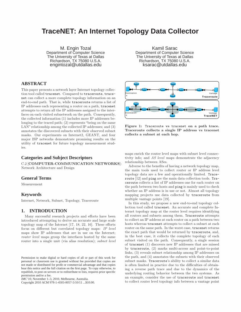
Figure 1: Traceroute vs tracenet on a path trace.Traceroute collects a single IP address vs tracenetcollects a subnet at each hop.
maps enrich the router level maps with subnet level connec-tivity info; and AS level maps demonstrate the adjacencyrelationship between ASes.
Adverse to the benefits of having a network topology map,the main tools used to collect router or IP address leveltopology data are a few and operationally limited. Trace-
route [12] and ping are the main data collection tools. Tra-ceroute collects a list of IP addresses one for each router onthe path between two hosts and ping is mainly used to checkwhether an IP address is in use or not. Almost all topologymapping projects use data collected by traceroute frommultiple vantage points [19].
In this study, we propose a new end-to-end topology col-lection tool called tracenet. An accurate and complete In-ternet topology map at the router level requires identifyingall routers and subnets among them. Traceroute attemptsto collect an IP address at each router on a path between twohosts whereas tracenet attempts to collect a subnet at eachrouter on the same path. In the worst case, tracenet returnsthe exact path that would be returned by traceroute, and,in the best case, it collects the complete topology of eachsubnet visited on the path. Consequently, a single sessionof tracenet (1) discovers new IP addresses that are missedby traceroute, (2) marks multi-access and point-to-pointlinks, (3) reveals subnet relationship among IP addresses onthe path, and (4) annotates the subnets with their observedsubnet masks. Traceroute’s ability to collect a similar datais often limited in practice due to the difficulties of obtain-ing a reverse path trace and due to the dynamics of theunderlying routing behavior between the two systems. Asan example, consider the use of traceroute and tracenet
to collect router level topology info between a vantage point
R R
R R R
R R R
1 2
3 4 5
6 8 9
P1P2P3
Traceroute
R R
R R R
R R R R
1 2
3 4 5
6 7 8 9
Network Topology
R R
R R R
R R R R
1 2
3 4 5
6 7 8 9
TraceNET
P1P2P3
A A A
B B B
C C CD D D
(a) (b) (c)
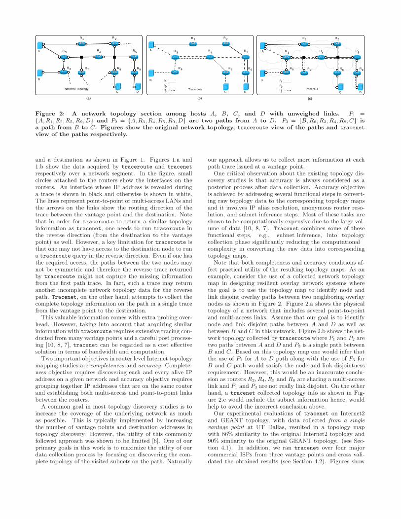
Figure 2: A network topology section among hosts A, B, C, and D with unweighed links. P1 ={A,R1, R2, R5, R9, D} and P2 = {A,R3, R4, R5, R9, D} are two paths from A to D. P3 = {B,R6, R3, R4, R8, C} isa path from B to C. Figures show the original network topology, traceroute view of the paths and tracenet
view of the paths respectively.
and a destination as shown in Figure 1. Figures 1.a and1.b show the data acquired by traceroute and tracenet
respectively over a network segment. In the figure, smallcircles attached to the routers show the interfaces on therouters. An interface whose IP address is revealed duringa trace is shown in black and otherwise is shown in white.The lines represent point-to-point or multi-access LANs andthe arrows on the links show the routing direction of thetrace between the vantage point and the destination. Notethat in order for traceroute to return a similar topologyinformation as tracenet, one needs to run traceroute inthe reverse direction (from the destination to the vantagepoint) as well. However, a key limitation for traceroute isthat one may not have access to the destination node to runa traceroute query in the reverse direction. Even if one hasthe required access, the paths between the two nodes maynot be symmetric and therefore the reverse trace returnedby traceroute might not capture the missing informationfrom the first path trace. In fact, such a trace may returnanother incomplete network topology data for the reversepath. Tracenet, on the other hand, attempts to collect thecomplete topology information on the path in a single tracefrom the vantage point to the destination.This valuable information comes with extra probing over-
head. However, taking into account that acquiring similarinformation with traceroute requires extensive tracing con-ducted from many vantage points and a careful post process-ing [10, 8, 7], tracenet can be regarded as a cost effectivesolution in terms of bandwidth and computation.Two important objectives in router level Internet topology
mapping studies are completeness and accuracy. Complete-ness objective requires discovering each and every alive IPaddress on a given network and accuracy objective requiresgrouping together IP addresses that are on the same routerand establishing both multi-access and point-to-point linksbetween the routers.A common goal in most topology discovery studies is to
increase the coverage of the underlying network as muchas possible. This is typically implemented by increasingthe number of vantage points and destination addresses intopology discovery. However, the utility of this commonlyfollowed approach was shown to be limited [6]. One of ourprimary goals in this work is to maximize the utility of ourdata collection process by focusing on discovering the com-plete topology of the visited subnets on the path. Naturally
our approach allows us to collect more information at eachpath trace issued at a vantage point.
One critical observation about the existing topology dis-covery studies is that accuracy is always considered as aposterior process after data collection. Accuracy objectiveis achieved by addressing several functional steps in convert-ing raw topology data to the corresponding topology mapsand it involves IP alias resolution, anonymous router reso-lution, and subnet inference steps. Most of these tasks areshown to be computationally expensive due to the large vol-ume of data [10, 8, 7]. Tracenet combines some of thesefunctional steps, e.g., subnet inference, into topologycollection phase significantly reducing the computationalcomplexity in converting the raw data into correspondingtopology maps.
Note that both completeness and accuracy conditions af-fect practical utility of the resulting topology maps. As anexample, consider the use of a collected network topologymap in designing resilient overlay network systems wherethe goal is to use the topology map to identify node andlink disjoint overlay paths between two neighboring overlaynodes as shown in Figure 2. Figure 2.a shows the physicaltopology of a network that includes several point-to-pointand multi-access links. Assume that our goal is to identifynode and link disjoint paths between A and D as well asbetween B and C in this network. Figure 2.b shows the net-work topology collected by traceroute where P1 and P2 aretwo paths between A and D and P3 is a single path betweenB and C. Based on this topology map one would infer thatthe use of P1 for A to D path along with the use of P3 forB and C path would satisfy the node and link disjointnessrequirement. However, this would be an inaccurate conclu-sion as routers R2, R4, R5 and R8 are sharing a multi-accesslink and P1 and P3 are not really link disjoint. On the otherhand, a tracenet collected topology info as shown in Fig-ure 2.c would include the subnet information hence, wouldhelp to avoid the incorrect conclusion above.
Our experimental evaluations of tracenet on Internet2and GEANT topology, with data collected from a single
vantage point at UT Dallas, resulted in a topology mapwith 86% similarity to the original Internet2 topology and90% similarity to the original GEANT topology. (see Sec-tion 4.1). In addition, we ran tracenet over four majorcommercial ISPs from three vantage points and cross vali-dated the obtained results (see Section 4.2). Figures show
that around 60% of subnets observed by all three vantagepoints and roughly 80% of subnets observed by a particularvantage point is also observed from at least one other van-tage point. Experimental results promote the use of trace-net in case studies involving network topology mapping andnetwork analysis/debugging.The remainder of the paper is organized as follows. Next
section introduces the related work. Section 3 details theinternals of tracenet. Section 4 presents our experimentalevaluation results. Finally, Section 5 concludes the paper.
2. RELATED WORKTraceroute [12] has been the main tool to collect router
level topology data in the Internet. It sends TTL scopedpackets in order to make the routers located at each hopbetween a vantage point and a destination to return ICMPTTL-Exceeded messages. Each router reports one of its IPaddresses by setting it as the source address of the returnedICMP packet. All in all, traceroute returns a list of IP ad-dresses each belonging to a router at each hop on the path.Certain load balancing practices may affect the accuracy oftraceroute returned paths. A version of traceroute, calledParis traceroute [4], attempts to minimize the negative im-pact of such load balancing activities.Traceroute can use ICMP, UDP, or TCP based probes. It
has been reported that TCP traceroute is good at penetrat-ing through firewalls whereas ICMP traceroute is more im-mune to path fluctuations [15, 9]. Discarte project [20] setsrecord-route option of probe packets to force the compliantrouters to stamp the packets with outgoing IP address. Asa result, it obtains two IP addresses per hop.Various techniques have been used to discover more IP
addresses in topology mapping studies. Skitter/ARK [17]traces the same set of destinations from multiple vantagepoints. Rocketfuel [21] aims to reveal the map of a sin-gle AS by carefully selecting the sources and the destina-tions to include the target AS network on the path traces.AROMA [13] advocates the selection of trace destinationsfrom within the targeted network for better exploration ofthe network.The well-known ping tool uses direct probing to check if
a given IP address is in use or not. Census study [11] usesping to determine alive IP addresses on the Internet.Finally, our previous work [7] attempts to identify subnet
relation among the IP addresses collected in a traceroute
based topology collection study as a post processing step onthe data set.Tracenet, presented in this paper, is based on several ob-
servations related to IP address assignment practices androuting dynamics. Similar to traceroute, it obtains a sin-gle IP address at each hop, however, before moving to thenext hop, it attempts to collect the IP addresses sharingthe same LAN with the obtained IP address. At the end
of a tracenet run, we get a sequence of subnets between the
source and destination hosts. Unlike the approach presentedin [7], tracenet discovers subnet topologies as part of theonline data collection process.
3. TRACENETIn this section we develop necessary definitions, present
several observations regarding operational and topologicalcharacteristics of the Internet, and describe internals oftracenet.
A router level Internet graph consists of routers and sub-nets. Each router and subnet hosts at least two interfaces.A router R is identified by the set of interfaces that it hosts:R = {l1, l2, . . . , lm}. Similarly, a subnet, S, is identified bya set of interfaces that are directly connected to it: S ={l1, l2, . . . , ln}. An interface l has an associated IP addressdefined as lip and a hop distance with respect to a certainvantage point v, shown as lhv . Whenever the vantage pointv is obvious in a context, we drop v and use lh. Finally, inour discussions we use R.e, R.n, R.w, and R.s to refer tothe interface located on (e)ast, (n)orth, (w)est, and (s)outhof a router R.
3.1 DefinitionsIn this section we introduce several definitions that we use
in the rest of the paper.(i) Direct Probing is the process of sending a probe packetwith large enough TTL value destined to some IP address.It is used to test if the IP address is alive or not. In gen-eral a probe packet is an ICMP ECHO REQUEST; a UDPpacket destined to a likely unused port number; or the sec-ond packet of TCP handshake protocol. These probes force aresponsive router to send back an ICMP ECHO REPLY; anICMP PORT UNREACHABLE; or a TCP RESET packet,respectively.(ii) Indirect Probing is the process of sending a probepacket with a small TTL value destined to some IP addressin order to reveal an IP address of another router presumablylocated at TTL hops away on the path. The probe packetcould be of type ICMP, UDP, or TCP. Whenever the TTLreaches zero, a responsive router would notify the origina-tor of the probe message with an ICMP TTL EXCEEDEDpacket. The source address of this packet would be one ofthe IP addresses of the router based on its response config-uration as explained next.(iii) Router Response Configuration implies that arouter is configured to remain reticent or reveal a certaininterface’s IP address in its response to a direct or indi-rect probe (query) packet. To the best of our knowledge,routers on the Internet are configured with five types of re-sponse policies: nil interface routers are configured not torespond to any probe packet; probed interface routers re-spond with the address of the probed interface; incoming
interface routers respond with the address of the interfacethrough which the probe packet has entered into the router;shortest-path interface routers respond with the address ofthe interface that has the shortest path from the router backto the probe originator; and default interface routers re-spond with a pre-designated default IP address regardless ofthe interface being probed. Usually, responsive routers areconfigured to behave as probed interface routers for directprobes and any other configuration for indirect probes. Ob-serve that a router cannot be configured as probed interface
router for indirect queries. Additionally, routers may be con-figured with multiple response configurations with respect tothe protocol type of a probe packet i.e. ICMP, UDP, or TCP.
3.2 ObservationsThis section presents a set of operational and topological
observations on the Internet.(i) Hierarchical Addressing details the common IP ad-dress assignment practices and refers to the Classless Inter-Domain Routing (CIDR) on the Internet (RFC 4632). Givenany subnetwork S on the Internet, the IP addresses assignedto the interfaces on S should share a common p bits prefix.Such a subnet S is said to have a /p prefix (subnet mask)and is shown in this paper as Sp.Any two IP addresses that have 31 or 30 bits common
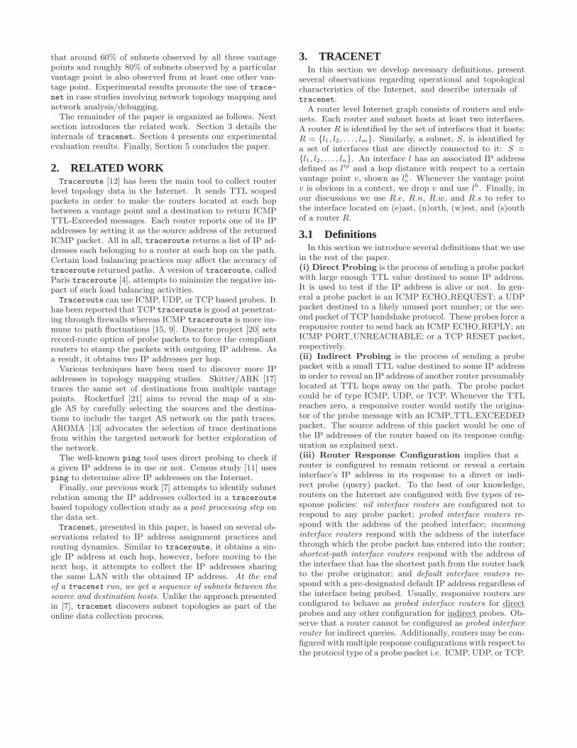
prefix are called mate-31 or mate-30 of each other.(ii) Fixed Ingress Router implies that as long as there isno path fluctuations caused by routing updates, load balanc-ing, or equal cost multi-path routing, there is a single pathfrom a vantage point to any interface on a given subnet S.As an important result; two immediately successive probepackets released from the same vantage point and destinedto two different interfaces on a subnet S are expected toreach the subnet through the same router. This fixed routeris called ingress router. In Figure 3, R2 is the ingress routerof the subnet S with respect to the vantage (see Section 3.7for more information on path fluctuations).A fixed ingress router is resistant to intermediate path
fluctuations as long as the fluctuated routes converge at or
before the ingress router.(iii) Unit Subnet Diameter implies that two interfaceson the same subnet are located at most one hop distanceapart with respect to a vantage point. That is, for inter-faces i, j ∈ S ⇒ |ihv − jhv | ≤ 1. In Figure 3, interfaces{R2.w,R3.s, R4.e, R6.n} ∈ S are at most one hop apart fromeach other with respect to the vantage.(iv) Mate-31 Adjacency implies that given that iip andjip are alive and mate-31 of each other, then i ∈ S ⇒ j ∈ S.
3.3 Network Exploration (Growing)In this section we detail how tracenet builds the subnet
accommodating an IP address obtained at a particular hopand introduce the related algorithm. Similar to traceroute,tracenet gradually extends a trace path by obtaining an IPaddress lip (or anonymous) via indirect probing at each hopon the way from a vantage point to a destination. However,after obtaining IP address lip at a particular hop, tracenetcollects other IP addresses that are hosted on the same sub-net which accommodates interface l before moving to thenext hop. We refer to the first step of acquiring an IP ad-dress at a certain hop via indirect probing as trace collection
and refer to the second step of collecting other IP addressessharing the same subnet as subnet exploration.Given an acquired IP address lip at trace collection step,
the main idea of subnet exploration is forming a subnet of/31 which covers lip and growing it as long as it does notconflict with one of the heuristics (Section 3.5) that we usefor verifying the authenticity of the subnet.Figure 3 freezes a tracenet session P = {. . . , R2.e, R4.e}
at hop d. Interface R2.e was acquired at previous hop andinterface R4.e is obtained at current hop via indirect prob-ing in trace collection mode. Those two interfaces are calledingress interface and pivot interface, respectively. The routerhosting the ingress interface (R2 in Figure 3) is called theingress router. In the figure, the interface R2.w, which islocated on the ingress router R2 and accommodated on thesame subnet with the pivot interface R4.e, is called contra-
R R
VantageDestination
S 24
4 2Vantage
hop d-1hop d
R1
1
hop d-2
R
R
R
R
R .e R .e R .s
Interface Legend
R
R
RR
3
5
6
7i
i
i
i.e
.n
.w
.s
ingresscontra-pivotpivot
Figure 3: Subnet Exploration. Observed subnet isgrown around the pivot interface discovered in tracecollection mode by forming /31, /30, ... subnets.
pivot interface. Observe that the interface R4.e belongs tosubnet S which hosts a number of other interfaces that wewant to discover.
To fully discover a subnet under investigation (S in Fig-ure 3), tracenet forms a temporary subnet starting from/31 which covers the pivot interface and grows the subnetwith decreasing prefix lengths (increasing subnet sizes). Foreach formed subnet, it directly probes the possible IP ad-dresses within the range of the subnet to ensure that theprobed IP address is assigned to an interface. Then, it ap-plies the heuristics defined in Section 3.5 to decide whetheror not the probed candidate IP address is on the subnet be-ing explored. An investigated IP address breaking one of theheuristics implies that it is not on the subnet being built. Asa result, subnet growing process immediately stops and thesubnet gets shrunk to its last known valid state (i.e., the pre-vious subnet prefix) by removing all interfaces that do notbelong to the last valid state. Additionally, subnet growingstops if the number of successfully probed IP addresses fora subnet prefix is equal or less than half of the total numberof IP addresses that such a subnet could accommodate.
Algorithm 1 shows the pseudocode for subnet exploration.Let →֒ operator (read as “results in”) be a syntactical el-ement. 〈iip, ttl〉 →֒ 〈jip, RESPONSE MSG TY PE〉 im-plies that probing of an IP address iip with TTL value of tllresults in a response message of type RESPONSE MSGTY PE with jip as the source IP address field of the mes-sage. If probing does not yield any response message, thenjip and RESPONSE MSG TY PE are set to nil. In caseswhere we are not interested in the value of jip but only theresponse message type, we use “. . .” in place of jip.
In the algorithm, the outer loop forms temporary growingof subnets S′ starting from a /31 prefix. Inner loop traverseseach candidate IP address in S′ by first testing the alivenessof the IP address at distance d (line 6) and then applies theheuristics explained in Section 3.5 (line 7). As long as theheuristics hold for the current IP address, it is assumed to bepart of subnet S being gradually built (line 12). Wheneverany heuristic fails, the subnet gets shrunk to previous prefix(line 9). Obtaining an ICMP TTL-Exceeded message as aresult of the test at line 6 implies that the subnet is over-
grown and needs to be shrunk (lines 14-17). Lines 19-21ensure that more than half of the potential IP addresses ofS are utilized before growing S one more level further.
Algorithm 1 Subnet Exploration
Input: lingress, lpivot /*ingress and pivot interfaces respectively*/Output: S /*observed subnet*/1 S ← ∅2 S ← S ∪ {lpivot}3 for m← 31 to 0 do
4 Form temporary S′ covering lpivot with prefix m
5 for each lip ∈ S′ do
6 if 〈lip, jh〉 →֒ 〈. . . , ECHO REPLY 〉 then7 APPLY HEURISTICS TO l8 if l breaks any heuristics then
9 Sp ← m + 1 /*Shrink S and STOP*/10 return
11 else
12 S ← S ∪ {l}13 end if
14 else if 〈lip, jh〉 →֒ 〈. . . , TTL EXCD〉 then15 Sp ← m + 1 /*Shrink S and STOP*/16 return
17 end if
18 end for
19 if m ≤ 29 and |S| ≤ (232−m)/2 then
20 return
21 end if
22 end for
3.4 Subnet PositioningAs discussed in Section 3.1, routers usually report the
queried IP addresses in their reply messages to direct probes.However, for indirect probes, a router may report the IPaddress of the incoming interface, a default interface or theinterface on the shortest path from itself back to the van-tage point. Tracenet builds the subnet which accommodates
the interface obtained with indirect probing at trace collec-
tion mode. Therefore, it needs to correctly designate a pivotand an ingress interface, determine the distance to the pivotinterface from the vantage point, and decide whether or notthe subnet is on the trace path before growing the subnet(Section 3.3). Subnet positioning, discussed in this section,is the process of designating pivot and ingress interfaces, de-termining the distance of the pivot interface from the van-tage point and deciding if the subnet is on the trace path.In most cases, the perceived direct distance of a vantage
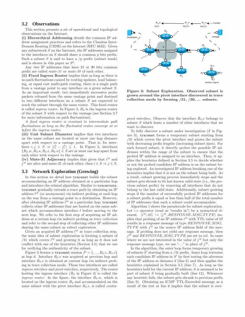
point to an interface l that is obtained indirectly at hop dis also d. In some other cases, however, it might differ byone or a few hops. Consequently, direct distance to otherinterfaces on the subnet accommodating l changes. To deter-mine the hop distance from the vantage point to an interfacel obtained with indirect probing at hop d in trace collectionmode, tracenet sends probe packets with increasing (for-ward) and decreasing (backward) TTL values starting fromd until it locates the exact location of l.Figure 4 shows portion of a tracenet session frozen at
hop d passing through the routers R1 and R3. Differentfrom Figure 3, it does not show the reported interfaces (filledblack) by the routers in order to discuss various scenarios.Let u and v be the two successive interfaces obtained fromR1 and R3 in trace collection mode at hops d − 1 and d,respectively.A subnet S to be explored in subnet exploration mode is
said to be “on-the-trace-path” if the indirect probe packetin trace collection mode passes through it. For instance, inFigure 4, if router R3 returns R3.e and the path to R3.e is P
VantageDest inat ion
Trace Path
Vantage
S
Path P
Path P’
Path P’’
S
R1
R2
R3
R4
R5
R6R7
R1R3hop d-1hop d
Destinaton
m
n R
Interface Legend
i.w
. .uv
R i.n
R i.e
R i.s
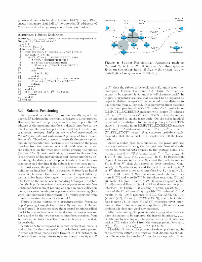
Figure 4: Subnet Positioning. Assuming path toSm and Sn is P or P ′′, if R3.v = R3.e then lpivot =R3.e, on the other hand, if R3.v = R3.s then lpivot =mate31(R3.e) or lpivot = mate30(R3.e)
or P ′′ then the subnet to be explored is Sm and it is on-the-trace-path. On the other hand, if it returns R3.s then thesubnet to be explored is Sn and it is “off-the-trace-path”. InFigure 4, tracenet assumes that a subnet to be explored athop d is off-the-trace-path if the perceived direct distance tov is different from d. Instead, if the perceived direct distanceto v is d and probing vip with TTL value d− 1 results in anICMP TTL EXCEEDED message with source IP addressuip, i.e., 〈vip, d− 1〉 →֒ 〈uip, TTL EXCD〉 then the subnetto be explored is on-the-trace-path. On the other hand, ifperceived direct distance to v is d and probing vip with TTLvalue d− 1 results in an ICMP TTL EXCEEDED messagewith source IP address other than uip i.e., 〈vip, d − 1〉 →֒〈lip, TTL EXCD〉 where l 6= u, tracenet probabilisticallyconcludes that the subnet to be explored is off-the-trace-path.
Under a stable path to a subnet S, the pivot interfaceis always selected among the farthest interfaces of a sub-net to be explored with respect to the vantage point, i.e.,∃lcontra−pivot ∈ S : ∀(l 6= lcontra−pivot), l
h = lhcontra−pivot +1, l ∈ S, and lpivot 6= {lcontra−pivot} in S. To illustrate inFigure 4, in case R3 returns R3.e and the path to subnetSm is P or P ′′ then R3.e serves as pivot interface. Con-versely, if R3 returns R3.s and the path to subnet Sn is Por P ′′ then some other alive interface l ∈ Sn (usually /31mate or /30 mate of R3.s) serves as pivot interface. Letmate31(lip) and mate30(lip) be functions returning /31 and/30 mate of a given IP address lip. Tracenet exploits mate-31 adjacency defined in Section 3.2 to determine the pivotinterface. In Figure 4, if sending a probe packet to /31mate of the IP address vip ∈ R3 with TTL value of vh = dresults in an ICMP response of TTL EXCEEDED, i.e.〈mate31(vip), vh〉 →֒ 〈. . . , TTL EXCD〉, then pivot inter-face is mate /31 or mate /30 of vip, otherwise pivot inter-face is v itself. Similar argument applies to /30 mate in caseprobing /31 does not yield any response.
After determining the pivot interface lpivot at a distanced for the subnet to be explored, the ingress interface lingress
is obtained by sending a probe packet to the pivot interfacewith a TTL value of d−1 from the vantage point. Formally,〈lippivot, l
hpivot − 1〉 →֒ 〈lipingress, TTL EXCD〉.
Algorithm 2 details the process of subnet positioning. Inthe algorithm dst(lip) is a function that determines the di-rect distance to the interface l from the vantage point. Lines
2-10 determine if the subnet to be explored is on-the-trace-path. Lines 11-21 designate the pivot interface and line 22designates the ingress interface of the subnet to be explored.
Algorithm 2 Subnet Positioning
Input: u, v, d /*last two interfaces obtained in trace collection modeat hop d− 1 and d*/
Output: lpivot, lingress /*pivot and ingress interfaces*/
1 vh ← dst(vip)
2 if vh 6= d then
3 Subnet to be explored is off-the-trace-path4 else
5 if 〈vip, vh − 1〉 →֒ 〈uip, TTL EXCD〉 then6 Subnet to be explored is on-the-trace-path7 else if 〈vip, vh − 1〉 →֒ 〈iip, TTL EXCD〉 where iip 6= uip
then
8 Subnet to be explored is off-the-trace-path9 end if
10 end if
11 if 〈mate31(vip), vh〉 →֒ 〈. . . , TTL EXCD〉 then
12 if mate31(vip) is in use then
13 lippivot
← mate31(vip)
14 else if mate30(vip) is in use then
15 lippivot
← mate30(vip)
16 end if
17 lhpivot ← vh + 1
18 else
19 lippivot
← vip
20 lhpivot ← vh
21 end if
22 lingress ← i where 〈lippivot
, lhpivot − 1〉 →֒ 〈iip, TTL EXCD〉
3.5 HeuristicsHeuristics given in this section are based on the common
IP address assignment practices and routing behavior on theInternet. They are devised to capture a subnet regardless ofits location at the core or edge of the Internet and regardlessof its being a multi access LAN or a point to point link.Let u and v be two consecutive interfaces obtained in trace
collection mode and i and j be the ingress and pivot inter-faces respectively determined by the subnet positioning al-gorithm. Note that u = i and v = j may or may not hold.Let lip be the IP address suspected to be sharing the same
subnet with jip and S be the subnet we are trying to infersuch that j, v ∈ S.
Vantage
pivot contra-p ivotin ter face inter face
Far FringeInterfaces
Far FringeInterfaces
Close Fringe Interfaces
Close Fringe Interfaces
Ingress Fringe Interfaces
Ingress Fringe Interfaces
Ingress Inter face
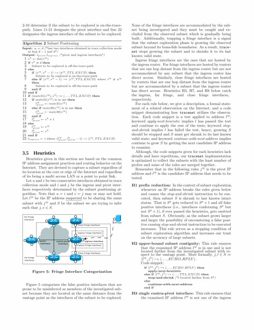
Figure 5: Fringe Interface Categorization
Figure 5 categorizes the false positive interfaces that areprone to be misinferred as members of the investigated sub-net because they are located at the same distance from thevantage point as the interfaces of the subnet to be explored.
None of the fringe interfaces are accommodated by the sub-net being investigated and they must be caught and ex-cluded from the observed subnet which is gradually beingbuilt. Additionally, trapping a fringe interface is a signalthat the subnet exploration phase is growing the observedsubnet beyond its bona-fide boundaries. As a result, trace-net stops growing the subnet and to shrinks it to its lastknown valid state.
Ingress fringe interfaces are the ones that are hosted bythe ingress router. Far fringe interfaces are hosted by routersthat are one hop distant from the ingress router but are notaccommodated by any subnet that the ingress router hasdirect access. Similarly, close fringe interfaces are hostedby routers that are one hop distant from the ingress routerbut are accommodated by a subnet that the ingress routerhas direct access. Heuristics H3, H7, and H8 below catchthe ingress, far fringe, and close fringe interfaces,respectively.
For each rule below, we give a description, a formal state-ment of a related observation on the Internet, and a codesnippet demonstrating how tracenet utilizes the observa-tion. Each code snippet is a test applied to address lip;keyword apply-next-heuristic implies l has passed the testand continue to apply the rest of the tests; keyword stop-
and-shrink implies l has failed the test, hence, growing Sshould be stopped and S must get shrunk to its last knownvalid state; and keyword continue-with-next-address impliescontinue to grow S by getting the next candidate IP addressto examine.
Although, the code snippets given for each heuristics lackdetails and have repetitions, our tracenet implementationis optimized to collect the subnets with the least number ofprobes and some of the rules are merged together.
Remember that in the following rules jip is the pivot IPaddress and lip is the candidate IP address that needs to betested.
H1 prefix reduction: In the context of subnet exploration,whenever an IP address breaks the rules given belowand causes the stop-and-shrink instruction to be exe-cuted, then subnet S is shrunk to last known intactstatus. That is Sp gets reduced to Sp +1 and all falsepositive interfaces (i.e., interfaces conforming Sp butnot Sp +1), if ever passed the heuristics, gets omittedfrom subnet S. Obviously, as the subnet grows largerand larger the possibility of encountering a false posi-tive causing stop-and-shrink instruction to be executedincreases. This rule serves as a stopping condition ofsubnet exploration algorithm and increases our truston the accuracy of large subnets.
H2 upper-bound subnet contiguity: This rule ensuresthat the examined IP address lip is in use and is notlocated farther from the investigated subnet with re-spect to the vantage point. More formally, j, l ∈ S ⇒〈lip, jh〉 →֒ 〈. . . , ECHO RPLY 〉.Code snippet:
if 〈lip, jh〉 →֒ 〈. . . , ECHO RPLY 〉 thenapply-next-heuristic
else if 〈lip, jh〉 →֒ 〈. . . , TTL EXCD〉 thenstop-and-shrink /*l located farther from S*/
else
continue-with-next-address
end if
H3 single contra-pivot interface: This rule ensures thatthe examined IP address lip is not one of the ingress
fringe interfaces. More formally, under a stable pathto subnet S, ∃lcontra−pivot ∈ S where lhcontra−pivot =
jh − 1 and ∀(l 6= lcontra−pivot), lh = jh where l ∈ S.
Code snippet:if 〈lip, jh− 1〉 →֒ 〈. . . , ECHO RPLY 〉 and lcontra−pivot =NIL then
icontra−pivot ← lapply-next-heuristic
else if 〈lip, jh−1〉 →֒ 〈. . . , ECHO RPLY 〉 and lcontra−pivot 6=NIL then
stop-and-shrink /*Second contra-pivot detected*/else
continue-with-next-address
end if
Note that, regarding Figure 3, R2 is the router hostingthe contra-pivot interface R2.w and any other interfaceof R2 seems to potentially pass the test given above.However, subnet exploration process demonstrated inAlgorithm 1 starts to grow the subnet from prefix /31and R2.w will be examined before any other interfacehosted by R2.
H4 lower-bound subnet contiguity: This rule increasesour confidence level on contra-pivot interface beforeadding l to the subnet S if the examined IP addresslip found to be a contra-pivot interface by H3. Moreformally, {l is found to be contra-pivot interface} ⇒〈lip, jh − 2〉 →֒ ¬〈. . . , ECHO RPLY 〉.Code snippet:
if lcontra−pivot = l and 〈lip, jh−2〉 →֒ 〈. . . , ECHO RPLY 〉then
stop-and-shrink
else
S ← S ∪ lcontinue-with-next-address
end if
H5 mate-31 subnet contiguity: This rule is a shortcutto add the examined IP address lip to subnet S ifit is /31 mate of the pivot. The same rule is validlip = mate30(jip) only if mate31(jip) is found not tobe in use. More formally, lip = mate31(jip) ⇒ l ∈ S.Code snippet:
if lip = mate31(jip) then
S ← S ∪ lcontinue-with-next-address
else
apply-next-heuristic
end if
H6 fixed entry points: This rule is used to test whetherthe examined IP address lip resides on a different sub-net located at the same distance with S or not. Moreformally, {l is found not to be the contra-pivot inter-face} ⇒ (〈lip, jh − 1〉 →֒ 〈i, TTL EXCD〉 or 〈lip, jh −1〉 →֒ 〈u, TTL EXCD〉.Code snippet:
if 〈lip, jh − 1〉 →֒ 〈i, TTL EXCD〉 thenapply-next-heuristic
else if S is on-the-trace-path and 〈lip, jh−1〉 →֒ 〈u, TTL EXCD〉then
apply-next-heuristic
else if 〈lip, jh − 1〉 →֒ 〈k, TTL EXCD〉 wherek 6= i and k 6= u then
stop-and-shrink
else if 〈lip, jh − 1〉 →֒ 〈i, ECHO RPLY 〉 thenstop-and-shrink
end if
Remember that u is obtained in trace collection modeand i is obtained by subnet positioning algorithm. Tominimize effects of path fluctuations both i and u areconsidered to be valid entry points to subnet S. Notethat the rule is valid in case i and/or u are anonymous.
H7 upper-bound router contiguity: This rule is usedto detect whether the examined IP address lip is oneof the far fringe interfaces or not. More formally, l ∈S ⇒ 〈mate31(lip), jh〉 →֒ ¬〈. . . , TTL EXCD〉.Code snippet:
if 〈mate31(lip), jh〉 →֒ 〈. . . , TTL EXCD〉 thenstop-and-shrink /*Far Fringe interface detected*/
else
apply-next-heuristic
end if
A router hosting an interface that resides on S at dis-tance jh also hosts some other interfaces that are noton S. Those interfaces may pass all the rules givenabove and they must be eliminated.
To illustrate, in Figure 3, R6.w or R4.s behaves as ifthey are on the subnet. However, a probe directedto their /31 mates with TTL = d result in a TTL-Exceeded message with a very high probability. Con-versely, /31 mate of an interface that is really on sub-net S, for example /31 mate of R6.n must result in anICMP Echo-Reply or anonymous.
Note that if l is a far fringe interface, then the probepacket destined to its /31 expires one hop earlier. Incase probing /31 mate of lip does not yield any re-sponse or yields an ICMP Host-Unreachable the sameheuristic is performed with /30 mate.
H8 lower-bound router contiguity: This rule is used todetect whether the examined IP address lip is one ofthe close fridge interfaces or not. More formally, l ∈S ⇒ 〈mate31(lip), jh − 1〉 →֒ ¬〈. . . , ECHO RPLY 〉such thatmate31(lip) 6= lipcontra−pivot.Code snippet:
if mate31(lip) 6= lipcontra−pivot
then
if 〈mate31(lip), jh − 1〉 →֒ 〈. . . , ECHO RPLY 〉 thenstop-and-shrink /*Close Fringe interface detected*/
else
apply-next-heuristic
end if
end if
To illustrate, in Figure 3, interface R7.n behaves asif it is on the subnet being investigated. However, aprobe directed to its /31 mate with TTL = d results inan ICMP Echo-Reply if the /31 mate is on the ingressrouter of the subnet being investigated. If probing/31 mate of lip does not yield any response or yieldsan ICMP Host-Unreachable, the same heuristic is per-formed with /30 mate. In case the subnet betweenR2 and R7 accommodates more than two interfaces,all false positive interfaces will be added to the inves-tigated subnet until tracenet encounters an interfacewhose /31 or /30 mate is located on the ingress router.Remember that whenever tracenet traps a false posi-tive interface, it shrinks S by removing all false positiveinterfaces from S.
H9 boundary address reduction: A final subnet that ispopulated with interfaces passing all the tests abovecannot contain any of the boundary addresses, i.e., net-work address and broadcast address, unless Sp = 31.As a post processing task after collecting the subnet,as long as the subnet contains a boundary address,tracenet divides the subnet S into S1 and S2 whereSp1= Sp
2= Sp − 1 drops Si if j /∈ Si.
Remember that these nine heuristics are not designed forany specific type of network but are generic enough to workover various subnet configurations appearing on the Inter-net.
3.6 Probing OverheadThe exact number of probes for a tracenet session de-
pends on the length of the trace, utilization/configurationof the IP addresses of the subnet being explored as well asits fringe subnets. In this section we give a model for lowerand upper bounds on the probing complexity as a functionof the size |S| for a subnet S.
For each subnet Si, initial cost is retrieving an IP ad-dress at the trace collection mode and determining pivotand ingress interfaces at the subnet positioning phase. Theformer requires a single probe and the latter requires one orthree probes depending on the position of the subnet.For each interface l on Si; intermediate cost is incurred
by heuristics and it depends on the type of l: no probingoverhead for pivot interface; if l is /31 (or /30) mate ofthe pivot interface, then only H2 and H5 are applied; if lis contra pivot interface then, H2, H3, and H4 are applied;and otherwise, H2 to H4 and H6 to H8 are applied. Amongthose heuristics, H5 does not require probing, H7 and H8may take one or two probes depending on the existence ofmate31(lip), and the rest takes a single probe each whereboth H3 and H6 requires the same single probe.For each subnet Si; final cost is incurred by encountering
a stopping condition and H9. Heuristic H9 has no probingoverhead. On the other hand, stopping condition can beencountered because of either Si being under-utilized (lines19-21 of Algorithm 1) or trapping into a stop-and-shrinkstatement. The former has no probing cost, the latter de-pends on the number of heuristics applied until executingthe stop-and-shrink statement.The lower bound on probing overhead is when the dis-
covered subnet S is a point-to-point link in which case onlyheuristics H2 and H5 are applied. Assuming, as the mosttypical case, the stopping condition is an immediate stop-and-shrink statement execution and the subnet is on-the-trace-path, the total cost is only four probes for discoveringthe point-to-point subnet.The upper bound of probing overhead is when the dis-
covered subnet S is off-the-trace-path and is a multi accessLAN accommodating |S| > 2 interfaces. Each subnet hasa single contra-pivot interface which requires three probes.Let lip 6= mate31(ipivot), ∀(l ∈ S), hence, ∀(l ∈ S) requiresall heuristics H2-H8 where heuristics H7 and H8 require twoprobes each. Also let the execution of the stopping conditionis delayed until the last heuristic, i.e., H8. Under this sce-nario, exploring S has the initial cost of three probes, finalcost of eight probes, and intermediate cost of three probesfor contra-pivot interface and seven probes for other inter-faces except pivot interface. As a result the upper boundprobing cost would be 7|S| + 7. Note that upper boundprobing complexity is a worst case scenario with probabil-
ity p < 1/(2⌈lg(2|S|−1)⌉
|S|
)of encountering and is only valid for
multi access LANs. This scenario takes place when an ad-ministrator utilizes half of an IP address range where onlythe odd or even numbered IP addresses are assigned to in-terfaces.
3.7 Path FluctuationsPath fluctuations [5] such as load balancing and equal
cost multi-path routing on the Internet depend on localnetwork traffic and router configuration that the packetspass through at a certain time. Although a single loadbalancing enabled router may potentially damage the au-thenticity of all trace paths passing on it, the effect is notthe same for tracenet because tracenet is based on the
stable ingress router concept rather than stable path trace con-
cept. That is, as long as two packets destined to two differ-ent IP addresses on the same subnet enter into the subnetthrough the same ingress router we are not interested if theytook the same path or not.
Heuristics defined above are meaningful at local sites iden-tified by two neighboring routers and immune to path fluc-tuations taking place before and after the sites as long as thehop distance is preserved. On the other hand, path fluctu-ations with varying hop distances while exploring a subnetpotentially causes the subnet being observed smaller thanits actual size.
In case a path fluctuation occurs at a local site, only H6among the rules given above gets affected. H6 expects thatthe packets destined to an interface on the subnet shouldenter into the subnet through certain router(s). The resultof a path fluctuation in the context of H6 would be stoppingto grow the subnet prematurely before it reaches its actualsize. In order to minimize this negative effect we resort tothe following methods: (1) our implementation of tracenetis completely based on ICMP probes which are shown to bethe least affected by load balancing [15] and (2) tracenet
always attempts to obtain at most two ingress routers to thesubnet being investigated (one is in trace collection modeand the other is in subnet positioning phase) and appliesthe test H6 against both routers. As a result, any packetentering to the subnet through either of the routers doesnot cause early halt of subnet exploration phase.
Moreover, as long as the intermediate path fluctuations,if ever occur, converge to an ingress router determined bytracenet, H6 does not get affected from it and correctlygrows the subnet. To increase the confidence level regardingpath fluctuations on a collected subnet, the same subnetcould be re-collected at a different time or from a differentvantage point.
3.8 LimitationsTracenet gradually enlarges a subnet around the IP ad-
dress lpivot after obtaining it via subnet positioning. Form-ing a subnet from a single IP address in a bottom-up fashionallows us to efficiently build large sized subnets compared tothe top-down approach which assumes a very large subnetand shrinks it by testing if each IP address is within theboundaries of the assumed subnet. Since tracenet stopsgrowing a subnet one level upwards in case it cannot fillat least half of the current level, sparsely utilized subnetsmight potentially get underestimated. A similar behaviorwould be observed when a consecutive portion of the IP ad-dresses space of a subnet remain silent to tracenet probes.In our implementation we re-probe an IP address if we donot get a response for the first probe. Moreover, if the pathlength to the ingress router changes in the middle of subnetexploration mode then the resulting subnet would also be anunderestimated subnet. Nevertheless, we believe that path
length changes in the middle of subnet exploration mode isnot very likely.Trace collection mode of tracenet is similar to traditional
traceroute. We plan to include the approach used in Paris
traceroute in order to keep the end-to-end paths more sta-ble. Finally, tracenet is designed mainly for IPv4 and itsextension to IPv6 remains as a future work.
4. EVALUATIONSIn this section we measure accuracy and consistency of
tracenet using two different types of experiments. In thefirst experiment set, we ran tracenet over Internet2 andGEANT and compare the collected subnets with the subnetlist that we derived using the information provided by theseresearch networks. Our comparisons are based on the rateof exact prefix length matches, similarity of subnet prefixlengths, and similarity of subnet sizes. For the second set ofexperiments, we ran tracenet from three different vantagepoints with a common target IP address set belonging tofour commercial ISPs (Sprintlink, AboveNet, Level3, NTTAmerica) and cross validate the collected subnets of eachvantage point against the others. Finally, we ran tracenet
from a single vantage point with ICMP, UDP, and TCPprobe packets to see its behavior with different protocols.Note that the main focus in our experiments is limited todemonstrating the accuracy and consistency of tracenet
rather than deriving complete [13, 21] or representative [14,3] sample topologies of commercial ISPs.Before continuing with the experiments and their evalua-
tions we would like to point out a few issues regarding theauthenticity of the subnets collected by tracenet. First ofall, tracenet is based on active probing and completely un-responsive subnets, i.e., subnets located behind a firewallwhich blocks probe packets or their responses, cannot becaptured. In this study we focus on sketching subnets atthe core of the Internet which are mostly open for discovery.Secondly, a subnet sketched by tracenet is only an observ-able subnet. That is, if there is a partially unresponsivesubnet, i.e., a subnet which consists of a mixture of respon-sive and unresponsive routers, tracenet can capture onlythe responsive portion of it. Related to observable subnetconcept, in case there is a subnet utilizing only a portion ofits whole IP address range, tracenet could only reveal whatit observes. To illustrate, if a network administrator utilizesonly a /30 portion of a subnet which is assigned a /29 subnetmask, tracenet collects it as a /30 subnet. Finally, Inter-net accommodates virtual subnets whose hosts connect toeach other through tunnels. Even though such a tunnel isrealized over a sequence of routers, tracenet captures it asa single subnet.
4.1 TraceNET Accuracy over Internet2 andGEANT
In this set of experiments, we run tracenet over Internet2and GEANT and collect their subnet topologies. We mea-sure the similarity of the collected topology against the de-rived subnet topologies of Internet2 and GEANT using fourdifferent metrics. In the first approach we directly comparethe rate of exact matches i.e., rate of subnets that are col-lected exactly as announced in the original topologies. Re-sults show that exact match rate of tracenet for Internet2is 73.7% and for GEANT is 53.5%. In the second approach,we exclude those unresponsive subnets, i.e., the ones that
do not reply back to our probes, and evaluate the exactmatch rate again. With this approach, our exact match rateraises to 94.9% and 97.3% for Internet2 and GEANT, re-spectively. In the third approach, we use each of the subnetprefix lengths in the original topology as a point in an n-dimensional euclidean space and measure the percentage ofsimilarity of the collected topology to the original topology.This approach allows us to asses the amount of deviationfrom the original topology rather than looking upon it as abinary match/not-match value. Results show that the sub-net prefix length similarity including unresponsive subnetsfor Internet2 and GEANT are 0.83 and 0.900 respectively.Our fourth approach is also based on the similarity in eu-clidean space, however, we use subnet size instead of prefixlength as the coordinate space. We obtain similarity rates of0.86 and 0.907 for Internet2 and GEANT respectively againincluding unresponsive subnets.
We first derive original Internet2[2] and GEANT[1] subnettopologies as our ground truth. Tracenet collects a subneton-the-fly while tracing towards a destination if it appearson the end-to-end path. However, we cannot control thepath taken by a packet and make it to pass through a cer-tain subnet or router. Thus, we build destination IP addresssets for Internet2 and GEANT by selecting a random IP ad-dress from each of their original subnets. Below we presentthe details of the experiments in the context of the afore-mentioned approaches.
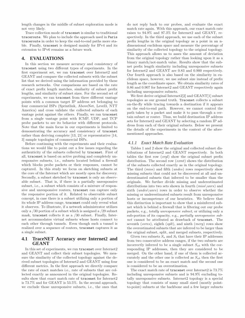
4.1.1 Exact Match Rate EvaluationTables 1 and 2 show the original and collected subnet dis-
tributions of Internet2 and GEANT respectively. In bothtables the first row (orgl) show the original subnet prefixdistribution. The second row (exmt) shows the distributionof the subnets collected exactly as in the original topology.The third (miss) and fifth (undes) rows respectively showmissing subnets that could not be discovered at all and un-derestimated subnets that inferred to be smaller than theoriginals. We further divide missing and underestimateddistributions into two sets shown in fourth (miss\unrs) andsixth (undes\unrs) rows in order to observe whether themissing or underestimated subnets result from unresponsivehosts or incompetence of our heuristics. We believe thatthis distinction is important to show that a misinferred sub-net which is behind a firewall that is filtering out our probepackets, e.g., totally unresponsive subnet, or utilizing only asub-portion of its capacity, e.g., partially unresponsive sub-
net cannot be attributed as drawback of tracenet. Theseventh (ovres), eighth (splt), and ninth (merg) rows showthe overestimated subnets that are inferred to be larger thanthe original subnet, split, and merged subnets, respectively.
Given two subnets Sa and Sb that have their IP addressesfrom two consecutive address ranges, if the two subnets areincorrectly inferred to be a single subnet Sab with the cor-responding IP addresses, then they are considered to bemerged. On the other hand, if one of them is collected ac-curately and the other one is collected as Sab then the firstone is considered to be an exact match and the second oneis considered to be an overestimation.
The exact match rate of tracenet over Internet2 is 73.7%including unresponsive subnets and is 94.9% excluding to-tally unresponsive subnets. Internet2 topology is a specialtopology that consists of many small sized (mostly point-to-point) subnets at the backbone and a few larger subnets
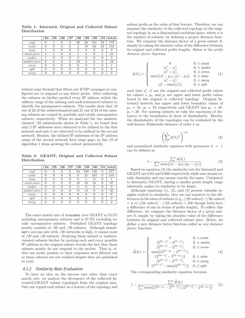
Table 1: Internet2, Original and Collected SubnetDistribution
/24 /25 /26 /27 /28 /29 /30 /31 total
orgl 6 1 0 2 26 20 101 23 179exmt 0 0 0 0 2 16 92 22 132miss 1 0 0 0 2 0 0 0 3
miss\unrs 4 1 0 2 1 4 8 1 21undes 1 0 0 0 2 0 0 0 3
undes\unrs 0 0 0 0 19 0 0 0 19ovres 0 0 0 0 0 0 1 0 1splt 0 0 0 0 0 0 0 0 0merg 0 0 0 0 0 0 0 0 0
behind some firewall that filters out ICMP messages or con-figured not to respond to any direct probe. After collectingthe subnets we further probed every IP address within theaddress range of the missing and underestimated subnets toidentify the unresponsive subnets. The results show that 19out of 22 of the underestimated and 21 out of 24 of the miss-ing subnets are caused by partially and totally unresponsivesubnets, respectively. When we analysed the two underes-timated /28 subnetworks shown in Table 1, we found thatonly 2 IP addresses were observed to be utilized in the firstnetwork and only 5 are observed to be utilized in the secondnetwork. Besides, the utilized IP addresses of the IP addressrange of the second network have large gaps, so line 19 ofalgorithm 1 stops growing the subnet prematurely.
Table 2: GEANT, Original and Collected SubnetDistribution
/24 /25 /26 /27 /28 /29 /30 /31 total
orgl 0 0 0 0 24 109 138 0 271exmt 0 0 0 0 0 41 104 0 145miss 0 0 0 0 0 1 0 0 1
miss\unrs 0 0 0 0 10 53 34 0 97undes 0 0 0 0 3 0 0 0 3
undes\unrs 0 0 0 0 11 14 0 0 25ovres 0 0 0 0 0 0 0 0 0splt 0 0 0 0 0 0 0 0 0merg 0 0 0 0 0 0 0 0 0
The exact match rate of tracenet over GEANT is 53.5%including unresponsive subnets and is 97.3% excluding to-tally unresponsive subnets. Published GEANT topologymostly consists of /30 and /29 subnets. Although trace-
net’s success rate with /30 networks is high, it misses mostof /29 and /28 subnets. Studying those missed or underes-timated subnets further by probing each and every possibleIP address in the original subnet reveals the fact that thosesubnets mostly do not respond to the probes. That is, ei-ther our probe packets or their responses were filtered outor those subnets are not realized despite they are publishedto exist.
4.1.2 Similarity Rate EvaluationTo have an idea on the success rate other than exact
match rate, we analyze the divergence of the collected In-ternet2/GEANT subnet topologies from the original ones.One can regard each subnet as a feature of the topology and
subnet prefix as the value of that feature. Therefore, we canmeasure the similarity of the collected topology to the origi-nal topology in an n-dimensional euclidean space, where n isthe number of subnets, by defining a proper distance func-tion. We compute the distance factor of a given subnet Si
simply by taking the absolute value of the difference betweenits original and collected prefix lengths. Below is the prefix
distance factor function:
d(Si) =
0 Si ∈ exmt|soi − sci | Si ∈ undes|soi − sci | Si ∈ ovres
max{|soi − pu|, |soi − pl|} Si ∈ miss
|soi − sci | Si ∈ merg|soi −max{sci}| Si ∈ splt
(1)
such that soi , sci are the original and collected prefix values
for subnet i, pu and pl are upper and lower prefix valuesfound in the original or collected topology. Original In-ternet2 network has upper and lower boundary values ofpu = 31, pl = 24 respectively and GEANT has pu = 30,pl = 28. For missing subnets we take the maximum of dis-tances to the boundaries in favor of dissimilarity. Hereby,the dissimilarity of the topologies can be evaluated by thewell known Minkowski distance of order k as
(n∑
i
d(Si)k
)1/k
(2)
and normalized similarity equation with parameter k = 1can be defined as
1−
∑ni d(Si)∑n
i max{(soi − pl), (pu − soi )}. (3)
Based on equation (3) the similarity rate for Internet2 andGEANT are 0.83 and 0.900 respectively while zero means to-tally dissimilar and one means exactly the same. Comparedto Internet2, GEANT, having a smaller prefix length rangeinherently makes its similarity to be larger.
Although equations (1), (2), and (3) present valuable in-sights related to similarity, they are not sensitive to the dif-ferences in the sizes of subnets (e.g., |/29 subnet|−|/30 subnet|= 4 vs |/23 subnet| − |/24 subnet| = 256 though both havea difference of one in terms of prefix length). To reflect thisdifference, we compute the distance factor of a given sub-net Si simply by taking the absolute value of the differencebetween its original and collected subnet sizes. Below, wedefine a new distance factor function called as size distance
factor function:
d̂(Si) =
0 Si ∈ exmt
|232−soi − 232−sci | Si ∈ undes
|232−soi − 232−sci | Si ∈ ovres
max{(232−pl − 232−soi ),
(232−soi − 232−pu)} Si ∈ miss
|232−soi − 232−sci | Si ∈ merg
|232−soi −max{232−sci }| Si ∈ splt
(4)
The corresponding similarity equation becomes
1−
∑ni d̂(Si)∑n
i max{(232−pl − 232−soi ), (232−so
i − 232−pu)}. (5)
Again for missing subnets we take the maximum of sizedistances to the boundaries in favor of dissimilarity.Based on the equation (5), the subnet size similarities be-
tween the collected and the original Internet2 and GEANTtopologies are 0.86 and 0.907 respectively while zero meanstotally dissimilar and one means exactly the same.
4.2 TraceNET Performance over the InternetIn this section we use tracenet on public Internet domains
to evaluate its performance. A limitation regarding the ver-ification of topology discovery tools over commercial ISPsis that their original topologies are considered to be propri-etary and are not available to the public. In our work, weresort to cross validation by running tracenet at three dif-ferent vantage points with the same target IP address set anddemonstrate the level of agreement/disagreement among theobserved subnets. The results show that all three vantagepoints agrees on around 60% of all collected subnets by aparticular vantage point. Additionally, roughly 80% of thecollected subnets by a particular vantage point is also veri-fied by at least one other vantage point. On the other hand,analyzing the collected subnets further show that some sub-nets are inferred to be larger when collected from anothervantage point. One explanation of this could be that like anyother active probing based topology collection tool, trace-net is affected from rate limiting routers or ISPs. That is,routers or ISPs regulate their responsiveness to probes basedon the traffic load or any other rate limiting policies. How-ever, all three vantage points consistently infers that most ofthe subnets at the non-edge Internet are point-to-point linksof /31 or /30 subnets. Then follows /29 subnets and a sharpcontinuing decrease after /29 with a small increase for /24subnets. We believe that /24 is a de-facto standard subnetmask for small or medium organizations, however, most ofthe organizations are also behind probe blocking firewalls.
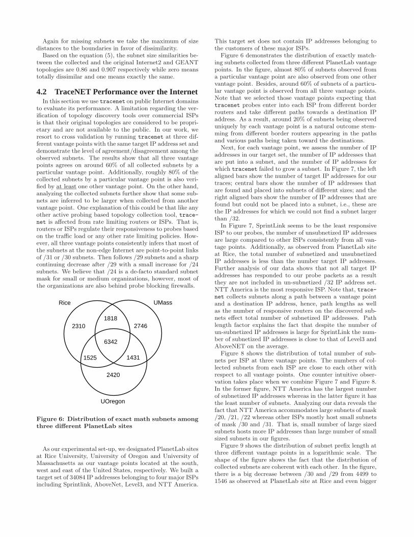
6342
1818
1525 1431
2310 2746
2420
Rice UMass
UOregon
Figure 6: Distribution of exact math subnets amongthree different PlanetLab sites
As our experimental set-up, we designated PlanetLab sitesat Rice University, University of Oregon and University ofMassachusetts as our vantage points located at the south,west and east of the United States, respectively. We built atarget set of 34084 IP addresses belonging to four major ISPsincluding Sprintlink, AboveNet, Level3, and NTT America.
This target set does not contain IP addresses belonging tothe customers of these major ISPs.
Figure 6 demonstrates the distribution of exactly match-ing subnets collected from three different PlanetLab vantagepoints. In the figure, almost 80% of subnets observed froma particular vantage point are also observed from one othervantage point. Besides, around 60% of subnets of a particu-lar vantage point is observed from all three vantage points.Note that we selected those vantage points expecting thattracenet probes enter into each ISP from different borderrouters and take different paths towards a destination IPaddress. As a result, around 20% of subnets being observeduniquely by each vantage point is a natural outcome stem-ming from different border routers appearing in the pathsand various paths being taken toward the destinations.
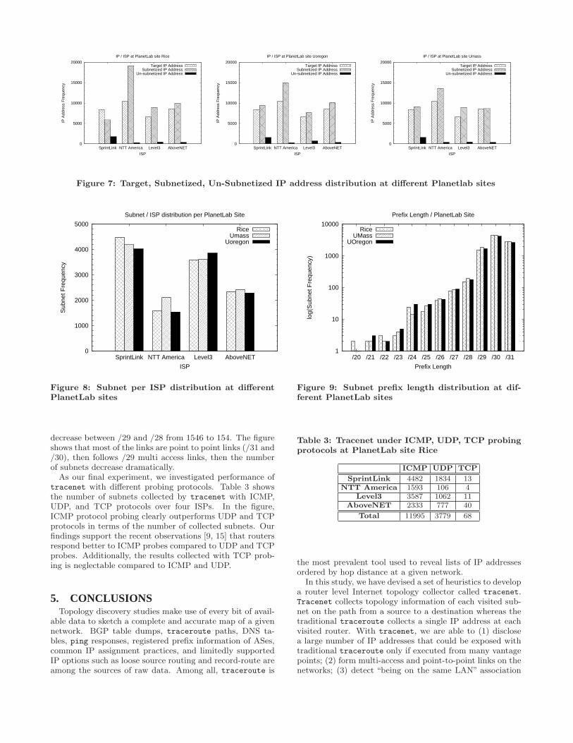
Next, for each vantage point, we assess the number of IPaddresses in our target set, the number of IP addresses thatare put into a subnet, and the number of IP addresses forwhich tracenet failed to grow a subnet. In Figure 7, the leftaligned bars show the number of target IP addresses for ourtraces; central bars show the number of IP addresses thatare found and placed into subnets of different sizes; and theright aligned bars show the number of IP addresses that arefound but could not be placed into a subnet, i.e., these arethe IP addresses for which we could not find a subnet largerthan /32.
In Figure 7, SprintLink seems to be the least responsiveISP to our probes, the number of unsubnetized IP addressesare large compared to other ISPs consistently from all van-tage points. Additionally, as observed from PlanetLab siteat Rice, the total number of subnetized and unsubnetizedIP addresses is less than the number target IP addresses.Further analysis of our data shows that not all target IPaddresses has responded to our probe packets as a resultthey are not included in un-subnetized /32 IP address set.NTT America is the most responsive ISP. Note that, trace-net collects subnets along a path between a vantage pointand a destination IP address, hence, path lengths as wellas the number of responsive routers on the discovered sub-nets effect total number of subnetized IP addresses. Pathlength factor explains the fact that despite the number ofun-subnetized IP addresses is large for SprintLink the num-ber of subnetized IP addresses is close to that of Level3 andAboveNET on the average.
Figure 8 shows the distribution of total number of sub-nets per ISP at three vantage points. The numbers of col-lected subnets from each ISP are close to each other withrespect to all vantage points. One counter intuitive obser-vation takes place when we combine Figure 7 and Figure 8.In the former figure, NTT America has the largest numberof subnetized IP addresses whereas in the latter figure it hasthe least number of subnets. Analyzing our data reveals thefact that NTT America accommodates large subnets of mask/20, /21, /22 whereas other ISPs mostly host small subnetsof mask /30 and /31. That is, small number of large sizedsubnets hosts more IP addresses than large number of smallsized subnets in our figures.
Figure 9 shows the distribution of subnet prefix length atthree different vantage points in a logarithmic scale. Theshape of the figure shows the fact that the distribution ofcollected subnets are coherent with each other. In the figure,there is a big decrease between /30 and /29 from 4499 to1546 as observed at PlanetLab site at Rice and even bigger
0
5000
10000
15000
20000
SprintLink NTT America Level3 AboveNET
IP A
ddre
ss F
requ
ency
ISP
IP / ISP at PlanetLab site Rice
Target IP AddressSubnetized IP Address
Un-subnetized IP Address
0
5000
10000
15000
20000
SprintLink NTT America Level3 AboveNET
IP A
ddre
ss F
requ
ency
ISP
IP / ISP at PlanetLab site Uoregon
Target IP AddressSubnetized IP Address
Un-subnetized IP Address
0
5000
10000
15000
20000
SprintLink NTT America Level3 AboveNET
IP A
ddre
ss F
requ
ency
ISP
IP / ISP at PlanetLab site Umass
Target IP AddressSubnetized IP Address
Un-subnetized IP Address
Figure 7: Target, Subnetized, Un-Subnetized IP address distribution at different Planetlab sites
0
1000
2000
3000
4000
5000
SprintLink NTT America Level3 AboveNET
Sub
net F
requ
ency
ISP
Subnet / ISP distribution per PlanetLab Site
RiceUmass
Uoregon
Figure 8: Subnet per ISP distribution at differentPlanetLab sites
decrease between /29 and /28 from 1546 to 154. The figureshows that most of the links are point to point links (/31 and/30), then follows /29 multi access links, then the numberof subnets decrease dramatically.As our final experiment, we investigated performance of
tracenet with different probing protocols. Table 3 showsthe number of subnets collected by tracenet with ICMP,UDP, and TCP protocols over four ISPs. In the figure,ICMP protocol probing clearly outperforms UDP and TCPprotocols in terms of the number of collected subnets. Ourfindings support the recent observations [9, 15] that routersrespond better to ICMP probes compared to UDP and TCPprobes. Additionally, the results collected with TCP prob-ing is neglectable compared to ICMP and UDP.
5. CONCLUSIONSTopology discovery studies make use of every bit of avail-
able data to sketch a complete and accurate map of a givennetwork. BGP table dumps, traceroute paths, DNS ta-bles, ping responses, registered prefix information of ASes,common IP assignment practices, and limitedly supportedIP options such as loose source routing and record-route areamong the sources of raw data. Among all, traceroute is
1
10
100
1000
10000
/20 /21 /22 /23 /24 /25 /26 /27 /28 /29 /30 /31
log(
Sub
net F
requ
ency
)
Prefix Length
Prefix Length / PlanetLab Site
RiceUMass
UOregon
Figure 9: Subnet prefix length distribution at dif-ferent PlanetLab sites
Table 3: Tracenet under ICMP, UDP, TCP probingprotocols at PlanetLab site Rice
ICMP UDP TCP
SprintLink 4482 1834 13NTT America 1593 106 4
Level3 3587 1062 11AboveNET 2333 777 40
Total 11995 3779 68
the most prevalent tool used to reveal lists of IP addressesordered by hop distance at a given network.
In this study, we have devised a set of heuristics to developa router level Internet topology collector called tracenet.Tracenet collects topology information of each visited sub-net on the path from a source to a destination whereas thetraditional traceroute collects a single IP address at eachvisited router. With tracenet, we are able to (1) disclosea large number of IP addresses that could be exposed withtraditional traceroute only if executed from many vantagepoints; (2) form multi-access and point-to-point links on thenetworks; (3) detect “being on the same LAN” association
among IP addresses; and (4) annotate subnets with theirobserved prefix values.As a result, tracenet could be utilized as an effective
data collection tool to improve completeness and correctnessof current and future topology mapping studies. Finally,an implementation of tracenet is publicly available on ourproject web site at http://itom.utdallas.edu.
6. REFERENCES[1] Geant2 looking glass. Available at
http://stats.geant2.net/lg/.
[2] Internet2 observatory data collections. Available athttp://www.internet2.edu/observatory/archive/data-collections.html.
[3] D. Achlioptas, A. Clauset, D. Kempe, and C. Moore. On thebias of traceroute sampling. In ACM STOC, Baltimore, MD,USA, May 2005.
[4] B. Augustin, X. Cuvellier, B. Orgogozo, F. Viger,T. Friedman, M. Latapy, C. Magnien, and R. Teixeira.Avoiding traceroute anomalies with Paris traceroute. InACM IMC, Rio de Janeiro, Brazil, Oct 2006.
[5] B. Augustin, T. Friedman, and R. Teixeira. Measuringload-balanced paths in the internet. In IMC Proceedings ofthe 7th ACM SIGCOMM conference on Internetmeasurement, New York, NY, USA, 2007.
[6] P. Barford, A. Bestavros, J. Byers, and M. Crovella. On themarginal utility of network topology measurements. In ACMInternet Measurements Workshop, San Francisco, CA, USA,Nov 2001.
[7] M. Gunes and K. Sarac. Inferring subnets in router-leveltopology collection studies. In ACM IMC, San Diego, CA,USA, Oct 2007.
[8] M. Gunes and K. Sarac. Resolving anonymous routers ininternet topology measurement studies. In IEEEINFOCOM, Phoenix, AZ, USA, Apr 2008.
[9] M. Gunes and K. Sarac. Analyzing Router Responsivenessto Active Measurement Probes. In PAM, Seoul, Korea, Apr2009.
[10] M. Gunes and K. Sarac. Resolving IP aliases in buildingtraceroute-based internet maps. IEEE/ACM Transactionson Networking, 17(6):1738–1751, Dec 2009.
[11] J. Heidemann, R. Govindan, C. Papadopoulos, G. Bartlett,and J. Bannister. Census and survey of the visible internet.In ACM IMC, Vouliag., Greece, Oct 2008.
[12] V. Jacobson. Traceroute. Lawrence Berkeley Laboratory(LBL), Feb 1989. Available fromftp://ee.lbl.gov/traceroute.tar.Z.
[13] S. Kim and K. Harfoush. Efficient estimation of moredetailed Internet IP maps. In IEEE ICC, Glasgow, Scotland,Jun 2007.
[14] A. Lakhina, J. Byers, M. Crovella, and P. Xie. Samplingbiases in IP topology measurements. In IEEE INFOCOM,San Francisco, CA, USA, Mar 2003.
[15] M. Luckie, Y. Hyun, and B. Huffaker. Traceroute probemethod and forward IP path inference. In ACM IMC,Vouliag., Greece, Oct 2008.
[16] H. Madhyastha, T. Isdal, M. Piatek, C. Dixon,T. Anderson, A. Krishnamurthy, and A. Venkataramani.iPlane: An information plane for distributed services. InOSDI, Seattle, WA, USA, Nov 2006.
[17] D. McRobb, K. Claffy, and T. Monk. Skitter: CAIDA’smacroscopic Internet topology discovery and tracking tool,1999. Available from http://www.caida.org/tools/skitter/.
[18] Y. Shavitt and E. Shir. DIMES: Distributed Internetmeasurements and simulations. Project pagehttp://www.netdimes.org.
[19] Y. Shavitt and U. Weinsberg. Quantifying the importanceof vantage points distribution in internet topologymeasurements. In IEEE INFOCOM, Rio de Janeiro, Brazil,Apr 2009.
[20] R. Sherwood, A. Bender, and N. Spring. DisCarte: Adisjunctive internet cartographer. In ACM SIGCOMM,Seattle, WA, USA, Aug 2008.
[21] N. Spring, R. Mahajan, D. Wetherall, and T. Anderson.Measuring ISP topologies with Rocketfuel. IEEE/ACMTransactions On Networking, 12(1):2–16, Feb 2004.
[22] University of Oregon. Route views project.http://www.routeviews.org.