tr2010 052 construction of stormwater management...
TRANSCRIPT

Construction of Stormwater Devices in the Auckland Region 177
16 Sand Filters
16.1 Introduction
Sand filters are used to attenuate peak stormwater flows, and treat stormw ater to reduce (or
remove) contamination by using different types of filter media. Sand filters are often used in
built up commercial or industrial areas because they can be installed underground and not
take up valuable surface land.
16.2 Device description
Sand filters are usually multi-chamber structures designed to treat stormwater runoff through
sedimentation (settling of heavier particles from the water column) and filtration (runoff
passes through the sand media to filter out pollutants). Stormwater run off from hard surfaces
including roofs, car parks and roads is normally collected by a series of roadside drains (kerb
and channel to catchpits) or spouting (downpipes for roof runoff). The stormwater is then
conveyed by a piped stormwater system to the sand filter for treatment.
Sand filters can be made up of a number of buried chambers, above ground chambers or a
combination of the two. Many sand filters arrive on-site as prefabricated units pre-drilled for
the connection with all of the internal components already installed (except the filter media
which still needs to be placed) and require only a connection to the inlet, outlet and joining of
the chambers (where there is more than one chamber).
The sand filter media is often made up of a mix, or layered with, sand and other materials,
such as peat or aged, mature compost to increase the removal of heavy metals. Care should
be taken when incorporating compost into sand filters, ensuring only mature, contaminant
free compost is used to reduce the risk of contaminant or nutrient leaching to filtered
stormwater. For industrial situations where specific contaminants may enter the stormwater,
the sand can be replaced or partially replaced with specially designed media such as ZPG
(zeolite, perlite and granulated activated carbon) to increase the removal of heavy metals and
so that additional pollutants may be removed. These special media systems are often
associated with cartridge filters. Two generic operational types of sand filters are typically
constructed, “surface” and “depth” filters.
Surface filters operate as a "cake" filter where a “schmutzdecke”, a complex biofilm layer
builds up on the surface of the filter that hydraulically controls the filtration rate. This is
generally very slow in the order of 2–5 cm hr-1
for surface filters. Solids are typically deposited
on the surface of the filter where they accumulate over time. Maintenance typically involves
removal of accumulated sediment and the top few centimetres of sand, which is replaced.
These filters are designed to capture a specified water quality volume and drain out between
24 and 48 hours.

Construction of Stormwater Devices in the Auckland Region 178
The other style of filter are depth filters, typically constructed from cylindrical cartridges. The
systems (typically manufactured) utilise coarse media with much higher flow rates (and
remove solids or other pollutants throughout the entire bed volume. Maintenance is
performed by complete removal and replacement of the filter media. These filters can be
designed to treat a design hydrograph or a water quality volume using upstream water quality
volume storage (sumps, rain tanks etc.) that captures, pre -treats and delivers a controlled
discharge to the filters. Since there are many variants to these types of filters, only systems
that have been reviewed and approved by the council are allowed. Designs must be
consistent with council design criteria and, in the case of an industrial or trade process, its risk
classification.
Sand filters include five main elements in their design as listed below.
Table 33
Key components of a typical sand filter.
Component Description
Inlet Stormwater runoff
enters the sand
filter from a piped
stormwater
reticulation system
passing through an
inlet manhole
where a diversion
weir is located (so
that in larger
storms the sand
filter is safely
bypassed).
Sedimentation
chamber
The first chamber in the sand filter slows stormwater runoff so that the
coarser, heavier particles contained in the runoff drop out. Sometimes
this is assisted by baffles (small walls or plates) at the bottom of the
chamber. Baffles are also often included in the top of the sedimentation
chamber to trap floatables (such as litter).
They are usually 25% of the area of the filtration chamber.
Filtration
chamber
Runoff enters the filtration chamber via a weir from the sedimentation
chamber. Runoff drains down through the sand filter media to the under
drainage system.
A spreader may be in place between the sedimentation and filtration
chamber to ensure the flows distribute evenly over the filter bed and do
not erode the top of the filter bed.
The filter media is normally 400 mm deep with a ponding area above at a
minimum of 400 mm deep.

Construction of Stormwater Devices in the Auckland Region 179
Component Description
Underdrainage
system
Located beneath the sand filter, the underdrainage system collects the
treated water via perforated pipes and conveys this to the outlet.
Outlet Collects flows from the underdrainage system and discharges them to
either a piped system or directly to the receiving environment (i.e.
waterways such as streams, the coast, etc).
For most sand filters, the outlet is piped to an outlet manhole which is
configured to allow for water quality samples of the effluent to be
collected.
Overflow
system
Usually consists of pipes located above the normal operating level of the
sand filter (i.e. above the sand filter bed and ponded water level). Flows in
the larger storms overflow from the sand filter through the pipes to the
stormwater reticulation system.
The ‘Washington’ sand filter is the most common in the Auckland region. Delaware sand
filters are often used around service stations or loading bays. Austin sand filters are usually
open sand filters and are not extensively used in the Auckland region.
Figure 83
Typical Washington sand filter.
Washington sand filters consist of a sedimentation chamber followed by the sand filter media
bed. They are completely enclosed, often pre -cast underground concrete units.
Manufacturers include Hynds and Humes. Pre-fabricated units treat smaller impervious areas
(usually up to 5,000 m2). Larger areas are normally serviced by a number of sand filter units,
or made to unique specifications. They are also known as ‘Underground Sand Filters’ or ‘Vault
Sand Filters’

Construction of Stormwater Devices in the Auckland Region 180
Figure 84
Typical Delaware sand filter (Source: ARC, TP10).
Delaware sand filters are often used around service stations or loading bays. They are
typically used for direct pavement runoff (from roads, car parks or forecourts). They are
generally not very wide but extend along the main drainage path and collect flows via a series
of grated covers (such as a dish channel). Water then overflows, usually by a series of weirs, or
single long weir to a layer of sand through which stormwater is filtered before entering an
outlet pipe. They are often called ‘Perimeter Sand Filters’ because they are often located at
the edge of paved areas.
Figure 85
Typical Austin sand filter [NZTA].
Austin filters consist of an inlet bay (sometimes with energy dissipaters), sedimentation basin
and a characteristic ‘jagged’ weir to distribute flows evenly on the sand filter bed. The

Construction of Stormwater Devices in the Auckland Region 181
sedimentation chamber is usually enclosed but the sand filter bed is not. They are usually
constructed on-site. An example of an Austin sand filter is located on the Upper Harbour
Highway in Hobsonville.
16.3 Guideline documents
Table34
Guidelines relat ing part icularly to sand filters include:
Publisher Title Description
ARC TP90 Erosion and Sediment
Control Guidelines for Land
Disturbing Activities in the
Auckland Region
These guidelines outline the principals of
erosion and sediment control and control
measures that should be used.
ARC TP124 Low Impact Design
Manual for the Auckland
Region
Approaches to site design and development
from a stormwater management context,
primarily applicable for residential land
development.
LTSA Integrated Stormwater
Management Guidelines for
the New Zealand Roading
Network
Provide guidance on a range of issues relating
to the management of stormwater run-off
from state highways and local roads in New
Zealand.
NSCC LB104 Management of
Driveway Runoff
Practice note to assist with the management of
driveway runoff in the Long Bay area including
specific requirements for stream protection
areas.
NSCC LB206 Flow Dispersers Practice note describing flow dispersers, these
are used to ensure the effectiveness of other
treatment devices and to prevent erosion.
NSCC LB301 Stormwater Treatment
for Roads
Practice note describing the on-site mitigation
of stormwater runoff that must be
incorporated into roading design to meet the
rules of the Long Bay Structure Plan Area.
NSCC LB303 Erosion – Sediment
Control Subdivision
Practice note providing guidance on the
requirements and descriptions of erosion and
sediment control practices at the subdivision
level.
NZWWA On Site Stormwater
Management Guideline
Provides guidance on the design of on-site
stormwater management devices for the
majority of applications in New Zealand.

Construction of Stormwater Devices in the Auckland Region 182
16.4 Standards and technical documents
Table 35
Below is a non-exhaustive list of some of the more applicable standards and technical documents that
relate to sand filters:
Title Description
AS/NZS 1254:2002
PVC Pipes and Fittings for
Stormwater and Surface
Water Applications
Specifies requirements for PVC pipes and fittings for
conveyance of stormwater or surface water. The Standard
includes requirements for both plain and structured wall pipes
and fittings.
AS/NZS 1260:2009
PVC-U Pipes and Fittings
for Drain, Waste and Vent
Application
Specifies requirements for PVCU pipes and fittings for sewer,
drain, waste and vent applications above-ground or below
ground and intended to be used where the pipeline is operating
under gravity flow and the operating pressure is low.
AS/NZS 2033:2008
Installation of
Polyethylene Pipe
Systems
Specifies methods for handling, storage, installation, testing and
commissioning of polyethylene (PE) pipelines, above or below
ground, for pressure and non-pressure applications conveying
liquids.
AS/NZS 2566.2:2002
Buried Flexible Pipelines –
Installation
Specifies requirements for the installation, field testing and
commissioning of buried flexible pipelines with structural design
in accordance with AS/NZS 2566.1.
NZS 3106: 2009
Code of Practice for
Concrete Structures for
the Storage of Liquids
Sets out requirements for design, materials and construction of
concrete structures for the storage of liquids. Covers
construction in reinforced and pre-stressed concrete and in
cement mortar.
AS/NZS 4129:2008
Fittings for Polyethylene
(PE) Pipes for Pressure
Applications
Specifies requirements for fittings to be used with polyethylene
pipe manufactured in accordance with AS/NZS 4130 or AS
2698.2 or POP-009. This Standard is applicable to fittings
manufactured for the conveyance of water, fuel gas, and other
fluids including compressed air.
AS/NZS 4130:2009
Polyethylene (PE) Pipes
for Pressure Applications
Specifies requirements for polyethylene pipes for the
conveyance of fluids under pressure. Such fluids include, but are
not restricted to, water, wastewater, slurries, compressed air,
and fuel gas.
AS/NZS 4671:2001
Steel Reinforcing
Materials
Sets out specifications for Australian and New Zealand Steel
reinforcing materials (bars, coils and welded mesh).
Requirements for chemical, mechanical and physical properties
for three different strength grades and the three different
ductility classes are also covered.
Construction of Stormwater Devices in the Auckland Region 183
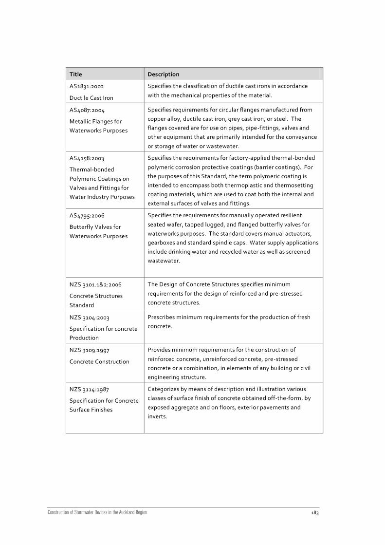
Title Description
AS1831:2002
Ductile Cast Iron
Specifies the classification of ductile cast irons in accordance
with the mechanical properties of the material.
AS4087:2004
Metallic Flanges for
Waterworks Purposes
Specifies requirements for circular flanges manufactured from
copper alloy, ductile cast iron, grey cast iron, or steel. The
flanges covered are for use on pipes, pipe-fittings, valves and
other equipment that are primarily intended for the conveyance
or storage of water or wastewater.
AS4158:2003
Thermal-bonded
Polymeric Coatings on
Valves and Fittings for
Water Industry Purposes
Specifies the requirements for factory-applied thermal-bonded
polymeric corrosion protective coatings (barrier coatings). For
the purposes of this Standard, the term polymeric coating is
intended to encompass both thermoplastic and thermosetting
coating materials, which are used to coat both the internal and
external surfaces of valves and fittings.
AS4795:2006
Butterfly Valves for
Waterworks Purposes
Specifies the requirements for manually operated resilient
seated wafer, tapped lugged, and flanged butterfly valves for
waterworks purposes. The standard covers manual actuators,
gearboxes and standard spindle caps. Water supply applications
include drinking water and recycled water as well as screened
wastewater.
NZS 3101.1&2:2006
Concrete Structures
Standard
The Design of Concrete Structures specifies minimum
requirements for the design of reinforced and pre-stressed
concrete structures.
NZS 3104:2003
Specification for concrete
Production
Prescribes minimum requirements for the production of fresh
concrete.
NZS 3109:1997
Concrete Construction
Provides minimum requirements for the construction of
reinforced concrete, unreinforced concrete, pre-stressed
concrete or a combination, in elements of any building or civil
engineering structure.
NZS 3114:1987
Specification for Concrete
Surface Finishes
Categorizes by means of description and illustration various
classes of surface finish of concrete obtained off-the-form, by
exposed aggregate and on floors, exterior pavements and
inverts.

Construction of Stormwater Devices in the Auckland Region 184
16.5 Construction considerations
16.5.1 Construction sequencing
If the sand filter is relatively small it may be able to be installed whilst other works continue.
Isolating the filter should be relatively easy depending on what provisions have been made in
the design for this. Normally the inlet and outlet can be blocked off at the incoming (usually
where the incoming diversion weir is located) and outgoing manholes.
To avoid siltation of the device, the unit should not be made operational until all works o n the
site have been completed.
16.5.2 Construction timing
Depending on the size of the filter that needs to be installed, the filter may be able to be
installed at any time throughout the year. Where earthworks consent is required, works will
be limited to between October and April.
16.5.3 Health and safety
Ensure that the finished tank level will be the same as that of the surrounding ground, and lids
flush with the ground surface so that there are no tripping hazards.
In addition, as confined space entry requires the use of harnesses and tripods, consideration
should be given to increasing the diameter of the manhole risers used for the access shafts.
16.5.4 Operation and maintenance
Ensure there is enough space for a sucker truck to be parked beside the filter otherwise
loadings for the design will need to take account of additional loadings caused by
maintenance machinery.
Consideration should be given to the installation of bollards around the tank to avoid vehicles
parking on the top of the sand filter increasing the loading on the lid (unless designed for it).
This will also ensure that the access lids are accessible for operation and maintenance.
Note that one of the major concerns with the operation and maintenance of filters is the
access into a confined space. This is particularly important for multi -chamber units where
access to adjacent chambers is limited. To ensure safety is not compromised, access shafts
should be provided for each chamber and consideration made for confined space entry barrier
requirements.

Construction of Stormwater Devices in the Auckland Region 185
16.5.5 Existing service utilities
Check that there are no services in the location where the treatment device is to be installed.
This will need to take account of all inlet and outlet pipes and manholes associated with the
filter.
16.5.6 Trees and vegetation
Check for any trees and vegetation that may need to be removed. If there are large
specimens, it is unlikely consent will be given for their removal.
16.5.7 Existing structures
Consider any additional services that may need to be strengthened or removed for the
installation of the device.
16.5.8 Water supply
A significant water supply will be needed for the water tightness test. Check for hydrants in
the area.
16.5.9 Site access
Most filter units weigh several tons and will need to be installed by a large excavator, hi-ab
truck or cranes. This often depends on the depth the device will be installed at. The site
should be inspected to ensure that access for machinery and equipment, and their use (i.e.
turning movements) are available. It is also necessary to confirm clearance from overhead
lines and other services.
16.5.10 Excavation
The site for the device must allow enough room for the excavation of the device and
installation of the associated inlet and outlet pipes.
Where large units are installed, consider whether spoil can be used on -site for landscaping or
other site works (subject to quality and earthworks and land use consents) or whether this will
need to be removed off-site. Often, the amount of spoil to be removed is considerable.
16.5.11 Buoyancy
If the device is located in an area with high groundwater table, the device may become
buoyant when emptied. Sub-soil drainage around the base of the unit will ensure this does
not occur.
Construction of Stormwater Devices in the Auckland Region 186
16.5.12 Foundations
It is essential the foundation of the filter unit are compacted and levelled as per the
construction plans. Any movement of the unit, potentially from base course subsidence, can
cause cracking in the unit and splitting of inlet or outlet connections. Where multiple u nits are
installed differential settlement may cause leakage between units. Because these units are
often buried leaks and structural failures may go unnoticed for some time causing
contamination of surrounding soil, groundwater and/or surface waterways.
16.5.13 Upstream pollutant traps
Upstream removal of gross pollutants prior to entry into the sand filter (e.g., gully traps, letter
screen) is highly recommended and often a requirement of the final design. Gross pollutants
create serious issues during maintenance and double the maintenance time required. For
sites where hydrocarbons may be an issue, installation of an oil and water separator up -flow
from the sand filter is also highly recommended and again may be a requirement of the final
design. Any additional items that can be installed to reduce the amount of time maintenance
crews need inside the chambers (which can be a confined space entry) should be included in
the construction of these filters.
16.5.14 Sand filter units
Consider pre-fabricated unit sizing. Sand filters are often prefabricated off site with internal
components already installed. This is often cheaper than constructing a cast -in-situ filter.
Levelling of the filter is also important to ensure that it operates correctly hydraulically.
16.5.15 Filter media
Special attention should be paid to the anticipated type and concentration of contaminants
and the media selected particularly to deal with these contaminants. It is imperative that the
correct media is installed for the filter to remove targeted pollu tants. For example, peat can
be incorporated into the sand filter to improve metals removal. As stated above, pre -
treatment using oil and water separators and gross pollutant traps are also recommended to
aid in maintaining contaminant removal efficiencies and ensure that the sand filter works as
intended.
16.5.16 Avoiding compaction of the filter media
For the filter to operate correctly, all efforts need to be made to ensure the filter media is not
overly compacted during installation. At the completion of media installation, hydraulic
compaction should be used, mechanical compaction avoided.
Construction of Stormwater Devices in the Auckland Region 187
16.5.17 Labelling of inlet and outlet
A common error in the installation of sand filters is that these are installed with the inlet and
outlet around the wrong way. Where single filter units are installed, this can easily occur as
they are literally delivered as a ‘box’ unit. To avoid this occurring, request that the
manufacturer clearly mark out the inlet and outlet.
16.5.18 Materials
All components internally, including inlet and outlet pipes, should be able to withstand
submergence and wetting over periods of time and have chemical resistance to minor
amounts of oils and hydrocarbons.
16.5.19 Lid levels
Whatever the existing surface, consider the finished level particularly in relation to the access
lids. All underground installations must be flush with the finished level. For projects where
the installation of the separator is only part of the works, the tank may need to be installed,
sealed off, marked it necessary, and access lids installed once other works are complete.
16.6 Construction specifications
Specifications for the construction of sand filter are often provided by the suppliers of the
sand filter. However, this is not always the case. Specifications should consider the following:
Table 36
Specifications that should be taken into consideration when constructing sand filters.
Area Items to include
Excavation • Specify the need for verification of ground conditions, excavation
support and removal of excess material.
• Where the excavation is greater than 1.5 m, geotextile material,
shuttering or shoring should be specified, depending on the ground
conditions present.
• The specifications should also call for the confirmation of ground
conditions before the filter is installed.
• Fencing around the excavation will also need to be installed.

Construction of Stormwater Devices in the Auckland Region 188
Area Items to include
Foundations • The bedding material should be confirmed and the specification should
also include any foundation details (i.e. hard fill, blinding layer and
reinforced concrete base (if necessary)).
• Requiring that the base course hard fill is well compacted will ensure
little to no movement of the unit in combination with a small diameter
blinding layer.
• Consider measures needed for buoyancy where the filter will be
installed in areas of high groundwater.
Filter unit • The size and type of separator to be installed. Usually access lids and
other internal components are included with the pre-cast units.
• Ensure that vehicle loading requirements are clearly specified for in -
ground filters, including access lids.
• Include specifications for epoxy and other water sealing agents for
joints, risers, connection pipes, connection between multiple units and
perimeter holes.
Filter media • The type (e.g. sand, peat, zeolite, combination media), grade and
depth of filter media.
• Samples of sand should be submitted for approval prior to installation.
• Sand specifications outlined in ARC TP10 are required when sand is
used as the filter medium. The sand should be clean, washed, inert
and free of contaminants.
• Particular mention should be made to ensure the media is not overly
compacted during installation.
• Hydraulic compaction requirements should also be discussed.
Inlet & outlets • Diameter and pipe type and material.
Backfill • Type of material appropriate for backfilling.
Reinstatement • Specify the final surfacing over the top of the filter.
• Note that most pre-cast units are designed for limited loadings and the
maximum depth of cover/vehicle loadings may need to be specified.
Testing • Specify a watertightness test to be carried out once the filter
installation is complete.
Example specifications are shown in Section 16.9. These cover some of the typical aspects for
construction of sand filters, but exclude particulars such as site est ablishment, health and
safety, testing, materials, and reinstatement, as these differ greatly depending on the
application.
These example specifications do not constitute a full specification for the construction of any
sand filter, and should be used as a ‘starter specification’ for guidance only. Each sand filter

Construction of Stormwater Devices in the Auckland Region 189
will be site specific and require careful consideration to ensure that all aspects of construction
are covered.
16.7 Construction monitoring
Table 37
Crit ical points to inspect during construction to ensure the device is installed correctly include:
Area Items to monitor
Excavation • Levels match construction plans and specifications.
• Any variation from the design plan may change the levels and
function of the sand filter separator and must be approved by the
design engineer or project manager.
Bedding/backfill
(foundations)
• Check bedding and backfilling meets specifications.
Sand Filter • Review of levels of unit and that the inlet and outlet point in the
correct direction of flow.
• All inlet and outlets are plugged during installation.
• Filter media depth is as per specifications (minimum 400 mm) and
level (must not be compacted).
Prior to lid
installation
• All levels and inverts have been checked against construction plans
and specifications, prior to chamber lids being secured.
• Photograph the filter prior to fitting the lid and include in the
operation and maintenance manual. This will aide any future
troubleshooting.
Access ladders • Access hatches installed and line up with unit ladders and ladders
line up.
Water tightness • All inlet and outlets of the chamber plugged/covered during
installation.
• Water tightness test (refer specifications) shows water loss is less
than 5% of total volume.

Construction of Stormwater Devices in the Auckland Region 190
16.8 Photo gallery – sand filters
Figure 86
Uncovered Austin sand filter Upper Harbour Highway, note that surface biofilm on the surface which can
clog the filter bed and reduce infiltrat ion rates. [NZTA]
Figure 87
Close up view of the algal crust on the Austin sand filter media on Upper Harbour Corridor. [NZTA]
Construction of Stormwater Devices in the Auckland Region 191
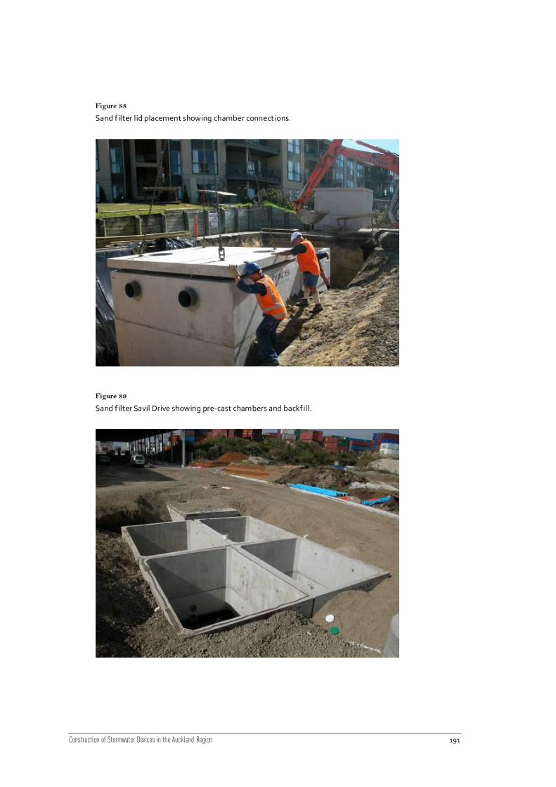
Figure 88
Sand filter lid placement showing chamber connections.
Figure 89
Sand filter Savil Drive showing pre-cast chambers and backfill.

Construction of Stormwater Devices in the Auckland Region 192
Figure 90
Sand filter (SF1250) showing baffle wall.
Figure 91
Sand filter Ward Street showing filter media in place.

Construction of Stormwater Devices in the Auckland Region 193
16.9 Construction specification example – sand filters
16.9.1 Site preparation
16.9.1.1 Clearance
Existing trees around the sand filter site shall be protected and those identified for removal on
the drawings shall be removed. The Contractor shall comply with any conse nt or District Plan
requirements concerning the preservation, trimming or transplanting of trees, shrubs, etc.
16.9.1.2 Topsoil
The Contractor shall strip the topsoil from all areas to be excavated, filled or otherwise
disturbed due to the construction of the contract works, and stockpile it in an approved
location. The depth of topsoil stripped shall be:
at least 300 mm in farmland, residential property or other cultivated areas; or
at least 150 mm elsewhere; or
the full depth of topsoil where less than the above depths exist.
16.9.1.3 Disposal of material and rubbish
All materials arising from site clearance which are surplus to or unsuitable for use in the Works
shall become the property of the Contractor and shall be disposed off the site.
All fences, buildings, structures and encumbrances of any character, except those that are
earmarked for removal by others, upon or within the limits of the site, shall be removed by the
Contractor and disposed of as directed by the Engineer.
16.9.1.4 Site fencing
The work area (excavations, stock-pile areas, etc) shall be adequately fenced to delineate their
extent and to fulfil the Contractor’s obligations of site safety and security, all to the
satisfaction of the Engineer.
16.9.1.5 Drainage
The Contractor shall keep excavations free of water during construction and shall dispose of
the water in an approved manner. During the placing and compacting of material in
excavations, the water level at the locations being refilled shall be maintained below the
bottom of the excavation.
The Contractor shall supply, install, operate and maintain all pumping, plant, pipework,
subdrains and sumps and other equipment necessary for this purpose and shall maintain at
the site at all times, reasonable standby plant in good working condition.

Construction of Stormwater Devices in the Auckland Region 194
16.9.1.6 Disposal of water
Water from either sand filter installation, surface drainage of the site, or dewatering of
excavations shall be treated (e.g. passed through a silt fence, settling pond or other
treatment) in accordance with ARC requirements prior to discharge, and shall contain no more
than 100 mg L-1
of solids. Once treated to the required level, the water may be disposed of
downstream into the public road stormwater drain or public foul sewer subject to local council
and ARC approval. Where this cannot be achieved, water from excavations must be removed
off-site and disposed of in an approved manner.
Water from any lubrication system used for pipe installation may not be discharged from the
site without the approval of the Engineer.
16.9.1.7 Diversion of existing services
In the case of a sand filter, all stormwater shall be diverted from the location until post
construction and the Engineer is satisfied that the catchment contributing to the sand filter
has been completely stabilised so as to avoid contamination of the filters. This includes
stabilisation of the earthworks and related stockpiling from the installation of the sand filters.
16.9.1.8 Verification of levels
The Contractor shall take sufficient levels or cross-sections of the existing ground surfaces,
including the road surface to confirm the ground profile and levels shown on the drawings and
to ensure that the surfaces are reinstated to the levels existing at the start of the contract
works or shown on the drawings.
The Contractor shall also confirm the invert and lid levels of a ll wastewater and stormwater
lines and verify the depth of telecommunications, power, gas or other services which
transverse the sand filter location or are in the vicinity of the works. Any disagreement or
potential conflicts shall be reported to the Engineer before excavation is commenced.
16.9.2 Supply of sand filter
The manufacturer will typically supply the following components:
Sand filter bases.
Sedimentation chamber.
Sand filter risers.
Precast lids.
Manhole servicing entries.
Concrete lids.
Heavy duty frame and cover.
The contractor will typically provide/supply the following:

Construction of Stormwater Devices in the Auckland Region 195
Installation of the sand filter on-site and all associated pipework connections.
A suitable crane to lift and install the sand filter components.
Any holes to be drilled into the inlet pipes.
Any sealing material between manhole risers/lids, etc.
All pipes between any units/manhole risers.
The excavation of the hole.
Any additional throat risers.
Sealing of all pipes.
Any site work.
The removal of water from the excavated site to allow installation.
Any fill material to bring the level of the excavation up to the correct height prior to
installation of the sand filter.
16.9.3 Excavation
16.9.3.1 Verification of ground conditions
The Contractor shall include in his price for excavation in all material s encountered, that could
reasonably be anticipated from the geotechnical information provided, and from any further
investigation undertaken by the Contractor prior to Tendering. This shall include rock and/or
tree logs or stumps if geotechnical information suggests that the presence of rock and/or tree
logs or stumps is possible. This shall also include variable material in any filled and alluvium
ground identified in the geotechnical information.
"Rock" shall be material of sufficient strength and extent that in the opinion of the Engineer it
cannot be removed efficiently using a 20 tonne size digger fitted with an appropriate narrow
"rock" bucket, and requires more intensive means for efficient excavation.
16.9.3.2 Over excavation
If the Contractor takes out any material to a greater depth or width than shown on the
drawings or specified, without the instruction of the Engineer the extra depth or width shall be
filled either with concrete, approved hardfill, or excavated material as nominated by the
Engineer, and thoroughly compacted without any extra payment.
16.9.3.3 Excavation in road reserve
Excavation in road reserve shall be carried out in accordance with the specifications and
requirements quoted in the “Code of Practice for Working in the Road” and the LTA
requirements including any additional requirements as defined in the Road Opening Notice
and LTA Infrastructure Design Standards.

Construction of Stormwater Devices in the Auckland Region 196
16.9.3.4 Stockpiling and removal of excavated material
All excavated material required for fill shall be properly stockpiled with steep faces to allow
maximum drainage in an approved location inside the working area. Stockpiled material shall
be covered with geotextile or polythene if rain is forecast.
Stockpiled material which deteriorates and becomes unsuitable because of avoidable delays,
poor storage arrangements or other circumstances within the Contractor's control shall be
replaced with suitable material at the Contractor's own cost.
Where material is stockpiled off site the proposed stockpile site shall be submitted to the
Engineer for Approval.
16.9.3.5 Support
The Contractor shall support the sides of excavations with suitable shoring to comply with all
safety requirements and so that excessive widening of the excavation is avoided. Support may
be provided by use of shields, timber, sheet piling or other shoring systems, subject always to
the Engineer's agreement of the proposed method. Any such agreement given by the
Engineer shall not absolve the Contractor of this responsibility to minimise the area disturbed
by the works and to make the site safe.
Timbering or sheet piling shall (where possible), be drawn up and removed as the concreting
or backfilling progresses so as to ensure that all voids at the side, or in other places, are filled
as the contract works advance.
16.9.3.6 Excavation support left in place
Where the Engineer considers it necessary for shoring to be left permanently in the work he
may so order in writing, in which case payment will be made at the rate of half the new price
of such timber or sheet piles.
All shoring left in place shall be kept clear of the permanent contract works. The Engineer may
direct that shoring left in place be cut off at any specified level in which case payment will be
made only for the portion remaining in the ground.
The fact of any shoring being left in place, or not being left in place, shall not relieve the
Contractor from any responsibility for any settlement or other damage caused by his
operations. Backfill to all excavations shall meet the strength and compaction requirements
of the specification, and the reinstatement details given on the drawings.
16.9.4 Foundation
Shear strength testing of the bedding material for the foundation may be required by the
Engineer after excavation if the material is significantly different to that expected from the
geotechnical investigations provided.
Excavation for the foundations shall be 300 mm below the invert level of the sand filter boxes.
The founding material will consist of a 150 mm layer of hardfill on top of which will be a

Construction of Stormwater Devices in the Auckland Region 197
150 mm blinding layer of site concrete with two layers of 665 steel mesh reinforcing. The sand
filters will rest on top of this concrete slab.
The foundations are to be laid to the levels indicated in the drawings to within a tolerance of
±20 mm.
16.9.4.1 Reinforcement
Reinforcing steel shall comply with NZS 3106, NZS 3402 and NZS 3109.
16.9.5 Sand filter unit installation
If not provided, the holes for the inlet and outlet pipes shall be cored prior to lowering the
sand filter unit into place. The Contractor shall use the lifting systems recommended by the
manufacturers of the sand filter units (e.g. use a crane or excavator with lifting strops). Any
minor damage in the filter unit shall be made good by caulking an approved epoxy mortar to
completely fill the voids ensuring a watertight finish. Any badly dama ged components shall
be rejected.
The units will be numbered as per their position location; the contractor shall follow the
manufacturer’s plans to ensure that the units are placed in the correct place (i.e. not back to
front).
All joints between the floor and wall surfaces and any between vertical surfaces shall be made
watertight by the use of an approved epoxy mortar. All work surfaces are to be thoroughly
cleaned before applying and all laitance and grease removed. A 10 mm layer of epoxy mortar
is to be applied evenly over the full contact surface and carefully pressed down and secured in
position.
16.9.5.1 Connections between chambers
PVC pipes shall be installed to connect the chambers at the levels indicated on the drawings.
All PVC pipes shall be manufactured in accordance with AS/NZS 1260 “PVC Pipes and
Fittings” and installed in accordance with NZS 7643 “Installing PVC Pipes” and AS/NZS 2566
"Buried Flexible Pipelines".
16.9.5.2 Epoxy mortar
Epoxy mortar shall be used to seal the filter units joints and inlet and outlet pipe connections.
All constituents of the epoxy mortar (silica sand filler, resin and hardener) supplied shall be of
a brand and specification approved by the Engineer.
Epoxy mortar shall be certified by the manufacturer as follows:
Suitable for permanent immersion in contaminated stormwater.
Suitable for curing to full strength under waterlogged conditions.
Has a service life of 100 years.
No water permeation through thin (10 mm) sections.
Construction of Stormwater Devices in the Auckland Region 198
Suitable for adhering firmly to concrete to form durable watertight joints.
Suitable for bonding to wet concrete.
Manufacturer's instructions shall be followed strictly in storing, mixing, applying and curing.
After mixing, the mortar shall be used within the time period specified by the manufacturer.
All pre-hardened mortar shall be disposed off-site.
Do not use water and additional sand to mix.
Clean all work surfaces thoroughly before applying. Remove all laitance, free moisture and
grease from the surfaces. Avoid air entrapment by building up successive thin layers. Do not
apply in lumps.
16.9.5.3 Water tightness test
This test shall be undertaken prior to the installation of the filter components. The sand filter
units shall be plugged and filled completely and left for a period of 24 hours. A drop in water
of more than 5% of the total volume of the filter indicates that the sand filter is not watertight
and needs to be corrected before the internal components can be installed. The filter shall be
emptied of water once this test is complete.
The test shall be witnessed by the Engineer. If the filter units fail the test, the defects shall be
fixed and re-tested until the specification is met and the Engineer is satisfied.
16.9.6 Inlets and outlets
The inlet and outlet shall be constructed to connect to the sand filter from the stormwater
network as per the drawings. The diversion weir shall be constructed to the levels specified on
the drawings. The inlet connection joins shall be made watertight with an approved epoxy
mortar.
The connection shall be constructed by either drilling through the completed wall or in the
case of a fully supplied unit; through the inlet opening, subsequently sealing the annular gap
using an approved moisture compatible epoxy mortar. The pipe shall project a minimum of
25 mm and a maximum of 50 mm past the inside face of the sand filter.
Entrances to inlet and outlet pipes shall be plugged to prevent material entering the existing
stormwater system, Engineer to approve the plugging arrangement.
16.9.6.1 Concrete pipes and manhole risers
Concrete pipes and manhole risers shall be manufactured in accordance with NZS 3107:1978
“Precast Concrete Drainage and Pressure Pipes”. Installation shall be in accordance with
AS/NZS 3725 “Loads on Buried Concrete Pipes”.
16.9.6.2 Concrete
Concrete and formwork shall comply with NZS 3109 “Specification for Concrete Construction”
and subsequent amendments.

Construction of Stormwater Devices in the Auckland Region 199
Concrete supplied to the site shall comply with NZS 3108 “Specification for Concrete
Production – Ordinary Grade”.
Sulphate resistant concrete shall be 80% Duracem, 4% microsi lica and 16% general purpose
Portland Cement.
Concrete shall be Ordinary Grade of strength 17.5 MPa or 20 MPa, as shown on the drawings,
with maximum aggregate size 19 mm and slump 100 mm.
Concrete shall be supplied to site as batched ready mixed concrete from an approved supplier.
The Contractor shall keep a delivery record for each batch delivered to site. This shall record
the supplier, date, time, quantity delivered, mix code, specified strength, aggregate size and
slump.
The Contractor shall carry out a slump test on each batch delivered, and shall allow in his price
for 1 concrete test cube to be taken, cured and tested for each batch delivered. Concrete test
cubes will be required on the instruction of the Engineer.
Concrete surfaces that will be buried shall be surface finish U1 to NZS 3114.
16.9.6.3 Other materials
Where materials or workmanship is not covered by the drawings or this specification, the
requirements of the LTAs Infrastructure Design Standard shall be followed.
16.9.7 Underdrainage
The underdrainage shall be laid in the position detailed on the drawings. The portion of
underdrain through the sand filter shall be perforated or slotted PVC. The underdrainage shall
be wrapped with geotextile material with a large enough mesh to ensure that it does not clog
yet retains the filter media.
The underdrainage shall be backfilled with GAP40 gravel to a height of 50 mm above the pipe,
placed from a maximum height of 1 m above the underdrainage.
16.9.8 Dewatering valve and overflow pipe
The dewatering valve and overflow pipe shall be installed to the levels indicated on the
drawings. The valve shall be shop-fabricated by the pipe supplier or by an approved specialist
fabricator. Fabrication on site will not be permitted.
All surfaces of the body of the valve (inside and out) shall be coated internally and externally
to comply with AS 4158:2003. The valve shall be capable of bi-directional flow of water. The
valve shall be set so that the spindle is truly vertical.
The supplier shall supply with the valves, materials certificates relating to the composition of
the casing material.

Construction of Stormwater Devices in the Auckland Region 200
16.9.9 Filter media
The filter media shall be installed in 100 mm deep layers to the depths indicated on the
drawings. This shall be: sand, soil, gravel, peat or compost as specified in th e design. The
media shall be compacted hydraulically as follows:
Once the filter media is level with the overflow weir between the sedimentation and
filtration chamber, clean water shall be directed slowly into the sedimentation chamber
until the sedimentation and filtration chambers are completely full (i.e. just below the
overflow level).
The water will then be allowed to drain down through the filter until flow from the
underdrain ceases (this should be able to be monitored through the outlet chamber or
manhole or directly through the access chamber to the filtration chamber).
The filter will then be allowed to dry for a period of 48hrs and then shall be topped up the
filter media to the weir between the sedimentation and filtration chamber (as directed by
the Engineer).
16.9.10 Filter lids and chambers
Filter lids and chambers shall not be placed until all levels within the filter have been checked
and verified by the Engineer. This will involve shooting levels at all inlet, outlet, overflow,
floor and underdrainage levels to confirm ±20 mm accuracy from the drawings. Filter lids shall
be sealed with the approved epoxy mortar.
16.9.10.1 Chamber ladders
Chamber ladders shall be Grade 316 stainless steel and constructed in accordance with the
drawings.
16.9.10.2 Risers
Precast chamber risers shall consist of centrifugally spun sulphate resistant concrete pipes of
minimum Class 1 (S), with holes cast into the side for ladder rungs. The bottom ring shall be
seated in the rebate formed in the chamber base, and the joint sealed with a n approved epoxy
mortar.
Chamber risers shall be installed such that joints between rings are horizontal.
The Contractor shall use the lifting systems recommended by the manufacturers of risers (e.g.
chains with spreader bars). Any minor damage in riser tops shall be made good by caulking an
approved epoxy mortar to completely fill the voids ensuring a watertight joint between the
riser and the lid. Any badly damaged risers shall be rejected.

Construction of Stormwater Devices in the Auckland Region 201
16.9.10.3 Access hatches, throat, frame and covers
Access hatches shall be heavy duty pre-cast concrete designed to HNHO72 and of a suitable
thickness for the access diameter as set out in the drawings. The joint between the access
risers and lid shall be sealed with an approved epoxy mortar.
The access hatch throat shall be cast in-situ using 17.5Mpa concrete to a smooth finish. The
height of the throat shall not exceed 300 mm. Watertight epoxy bonding shall be provided
between the manhole throat and lid.
Access hatch frames and covers shall be watertight heavy duty ductile iron to AS3996 (80kN
loading), with a clear opening of 600 mm as detailed in drawings.
The frame of the hatch cover shall be fixed to the concrete lid/throat using epoxy mortar.
Concrete (17.5 MPa) haunching shall be provided around the frame.
The height of the manhole throat shall not be greater than 300 mm. The throat and any
subsequent extensions to the throat shall be cast in-situ using 17.5 MPa compacted watertight
concrete to a smooth finish. Plastering of the throat to achieve a smooth finish shal l not be
permitted. Severely honeycombed throats shall be rejected and shall be replaced fully. Any
minor defects shall be made good using epoxy mortar. Pre -cast throats shall not be
permitted. Watertight bonding shall be provided between the throat and the lid, and
between the existing part of the throat and subsequent extension.
16.9.11 Backfilling
The Contractor shall fill in, over and around the sand filter as soon as possible after any
concrete work has attained sufficient strength and after requirements re lating to inspection
and testing have been complied with.
Filling shall, as far as possible, be made up to the previously existing surface levels or to such
other levels shown in the drawings or as agreed by the Engineer as the work proceeds.
Previously excavated fill or engineered fill shall be used for backfilling as agreed with the
Engineer. Fill shall be compacted during filling in lifts up to a maximum of 200 mm thick and
shall be compacted to obtain a minimum dry density of 95%.
Prior to backfilling, all forms and debris shall be removed from the excavation.
16.9.11.1 Engineered fill
Engineered fill shall be approved by the engineer and be free of organic material, or any other
substances including excess moisture, which prevents satisfactory placing and comp action. It
shall be free of clay lumps and stones retained on a 75 mm sieve.
16.9.11.2 Buoyancy
The groundwater levels in the area shall be determined and the completed structure shall be
checked for buoyancy under the range of operating conditions including when some or all
tanks are empty.

Construction of Stormwater Devices in the Auckland Region 202
17 Oil and Water Separators
17.1 Introduction
Oil and water separators are only found on commercial or industrial sites and are designed to
meet the specific requirements of the site. Contractors involved in installing an oil and water
separator tend to be experienced installers with a good understanding of the functions.
17.2 Device description
Oil and water separators remove petroleum based oil and grease commonly referred to as
total petroleum hydrocarbons (TPH) from stormwater and small spills in areas where
hydrocarbon products are handled (e.g. substations, petrol stations, airports, refuelling zones,
storage terminals, industrial areas and workshops). TPH in the environment can be present in
a variety of forms including:
Free Oil - removed by separation through an oil and water separator.
TPH associated with solids: gravity separation for coarser sediments and filtration for
finer sediments.
Emulsified oils - Oils that have been associated with a detergent making it effectively
soluble in water. Difficult to remove, typically requires biological activity or caustic
reactions.
Mechanically solubilised oil - Mechanical action like vehicle movements and tyre traffic,
breaks oils into particles so small that they do not behave according to Stokes law but are
governed by electrostatic attraction and brownian motion. To remove this form of oil
requires very long-term settling, electro or chemical coagulation or filtration methods.
Oil and water separators are generally buried underground structures and can come as
package treatment plants or specifically designed for the site. Above-ground devices are also
available. Oil and water separators work by slowing down the inflow of contaminated
stormwater to allow oil droplets to rise to the surface. As the oil droplets combine they rise
faster (oil is less dense than water). Laminar flow (slow non-turbulent flow) is required for
optimum performance, so a critical component is the inlet baffle or screen which reduces the
speed of the water. Once the oil collects on the surface of the water, the clean water at the
bottom of the device is directed to the outlet by baffles and is then discharged from the
device. The oil collected on the surface of the device is generally removed by vacuum during
device maintenance.
Oil and water separators function by:
Slowing down stormwater flows from a small treatment area (e.g. service station,
refuelling depot, workshop) to allow oils, greases and other hydrocarbons to become
trapped and improve discharge water quality.

Construction of Stormwater Devices in the Auckland Region 203
Removes 90 to 95% of oil and grease to 15 mg L-1
of oil and grease when properly sized.
Underground devices can be used in built up areas, industrial areas and car parks.
Above ground devices can be installed or retrofitted to pre-existing infrastructure.
Figure 92
Key components of an oil/water separator.

Construction of Stormwater Devices in the Auckland Region 204
Table 38
Key components of an oil/water separator.
Device component Description
Inlet chamber with
baffle
Stormwater runoff enters the oil/water separator from the treatment
area only (via piped stormwater system). This chamber is where the
stormwater runoff is slowed down to allow the oil to start rising.
Collection chamber Oil collects on the surface, and in the case of the plate separator, is
where the plate pack is located.
Sediment baffle Sediment baffle is approximately 300 mm high from the base of the
collection chamber and located prior to the oil retaining baffle. It
makes sure sediment stays in the collection chamber to allow free
flow under the oil retaining baffle.
Plate pack (plate
separator only)
Plate packs are made of oleophilic materials that attract oil droplets
to their surface but do not adhere to them. As the oil droplets
become attracted, they collide and coalesce into bigger droplets
which increases the rate at which they separate from the water and
rise to the surface of the device.
Oil retaining baffle The oil retaining baffle leaves a 300 mm gap at the bottom to allow
clean stormwater to pass under it. This ensures all oil is retained
within the collection chamber.
Shut-off valve The valve controls the flow of stormwater exiting the separator. It
can be closed to trap spills and also for maintenance work on the unit.
Outlet chamber and
outlet pipe
This chamber collects the clean stormwater and discharges it to
either a piped system or directly to the receiving environment (i.e.
waterways such as streams and the coast).
All Auckland Regional Council (ARC) approved oil/water separators can be categorised as one
of the following:
Coalescing Collection Plate Separators (also simply called Plate Separators) – the plate
separator device slows the incoming water to a slow speed to allow time for the oil to rise
toward the surface. The contaminated water passes over a pack of closely spaced (10 mm)
plates that capture the oil. Oil droplets are attracted to the surface of the plate and then rise
to the surface of the tank where they settle out and are captured by baffles or skimmers.
Treated water passes under a baffle to ensure floating oils are retained within the storage
chamber.
API (American Petroleum Institute) Separators – the API device slows the incoming water to
allow time for the oil in the water to rise to the surface. Baffles keep the oil on the surface of
the storage section. Clean water passes under the baffle and out the outlet pipe.

Construction of Stormwater Devices in the Auckland Region 205
Figure 93
Typical plate separator Example 1 (Source: Mbeychok, 2007)
Figure 94
Typical API separator (Source: ARC, 2003).

Construction of Stormwater Devices in the Auckland Region 206
Figure 95
Typical plate separator Example 2 (Source: ARC, 2003).
17.3 Guideline documents
Guidelines relating particularly to oil and water separators include the following. Note that a
detailed review of council standards and guidelines should be carried out for every project, as
there are particular requirements for each council and these are frequently updated.

Construction of Stormwater Devices in the Auckland Region 207
Table 39
Guidelines relat ing to oil and water separators.
Publisher Title Description
ARC TP90 Erosion and Sediment
Control Guidelines for Land
Disturbing Activities in the
Auckland Region
These guidelines outline the principals of
erosion and sediment control and control
measures that should be used.
ARC TP124 Low Impact Design
Manual for the Auckland
Region
Approaches to site design and development
from a stormwater management context,
primarily applicable for residential land
development.
NSCC LB110 Other Technologies Practice note based on the ARC ’s TP10,
describing requirements for alternative
technologies to meet the Long Bay water
quality and quantity management objectives.
NZWWA On Site Stormwater
Management Guideline
Provides guidance on the design of on-site
stormwater management devices for the
majority of applications in New Zealand.
WCC Stormwater Solutions for
Residential Sites
Document providing guidance on
management practices applicable to
developments on individual residential lots
(<1000 m²). For use by engineers and
applicants for stormwater control building
permits for developments of this size.

Construction of Stormwater Devices in the Auckland Region 208
17.4 Standards and technical documents
Table 40
Below is a non–exhaustive list of some of the more applicable standards and technical documents that
relate to oil/water separators:
Title Description
AS4087:2004
Metallic Flanges for
Waterworks Purposes
Specifies requirements for circular flanges manufactured from
copper alloy, ductile cast iron, grey cast iron, or steel. The flanges
covered are for use on pipes, pipe fittings, valves and other
equipment that are primarily intended for the conveyance or
storage of water or wastewater.
AS4158:2003
Thermal-Bonded
Polymeric Coatings on
Valves and Fittings for
Water Industry Purposes
Specifies the requirements for factory-applied thermal-bonded
polymeric corrosion protective coatings (barrier coatings). For the
purposes of this Standard, the term polymeric coating is intended
to encompass both thermoplastic and thermosetting coating
materials, which are used to coat both the internal and external
surfaces of valves and fittings.
AS4795:2006
Butterfly Valves for
Waterworks Purposes
Specifies the requirements for manually operated resilient seated
wafer, tapped lugged, and flanged butterfly valves for waterworks
purposes. The standard covers manual actuators, gearboxes and
standard spindle caps. Water supply applications include drinking
water and recycled water as well as screened wastewater.
AS/NZS 1254:2002
PVC Pipes and Fittings
for Stormwater and
Surface Water
Applications
Specifies requirements for PVC pipes and fittings for conveyance
of stormwater or surface water. The Standard includes
requirements for both plain and structured wall pipes and fittings.
AS/NZS 2033:2008
Installation of
Polyethylene Pipe
Systems
Specifies methods for handling, storage, installation, testing and
commissioning of polyethylene (PE) pipelines, above or below
ground, for pressure and non-pressure applications conveying
liquids.
AS/NZS 2566.2:2002
Buried Flexible Pipelines
- Installation
Specifies requirements for the installation, field testing and
commissioning of buried flexible pipelines with structural design
in accordance with AS/NZS 2566.1.
AS/NZS 4671:2001
Steel Reinforcing
Materials
Sets out specifications for Australian and New Zealand Steel
reinforcing materials (bars, coils and welded mesh).
Requirements for chemical, mechanical and physical properties
for three different strength grades and the three different ductility
classes are also covered.

Construction of Stormwater Devices in the Auckland Region 209
Title Description
NZS 3101.1&2:2006
Concrete Structures
Standard
The design of concrete structures, specifies minimum
requirements for the design of reinforced and pre-stressed
concrete structures.
NZS 3104:2003
Specification for
Concrete Production
Prescribes minimum requirements for the production of fresh
concrete.
NZS 3109:1997
Concrete Construction
Provides minimum requirements for the construction of
reinforced concrete, unreinforced concrete, pre-stressed concrete
or a combination, in elements of any building or civil engineering
structure.
NZS 3114:1987
Specification for
Concrete Surface
Finishes
Categorizes by means of description and illustration various
classes of surface finish of concrete obtained off-the-form, by
exposed aggregate and on floors, exterior pavements and inverts.
17.5 Construction considerations
17.5.1 Construction sequencing
The oil and water separator can be installed while other works continue as it is relativ ely
simple to isolate depending on what provisions have been made in the design. Normally the
inlet and outlet can be blocked off at manholes. The shut down valve should not be used for
this purpose as any sediment can transfer to the device once the val ve is open – this should
always be done in manholes where possible.
To avoid siltation of the device, the unit should not be made operational until all works on the
site have been completed.
17.5.2 Construction timing
Normally only small excavations are required for the installation of separators and this can
usually be done without the need for an earthworks consent and at all times throughout the
year.
17.5.3 Health and safety
If underground, ensure that the tank will be level with the surrounding ground and lids flush
with the ground surface on completion so that there are no tripping hazards.

Construction of Stormwater Devices in the Auckland Region 210
17.5.4 Operation and maintenance
In an emergency, oil spill personnel will need to close the shut off valve. Consider including
signage inside the Toby box so personnel will be able to quickly determine the direction it
needs to be turned for shut off.
Valve keys should be provided close to the oil separator for this purpose.
17.5.5 Existing service utilities
Where the separator is to be installed underground, ensure that there are no existin g
underground service utilities where the treatment device is to be installed. The inlet and
outlet pipes, and the connection to them should also be considered.
17.5.6 Trees and vegetation
Most oil and water separators are relatively small and are predominantly located in industrial
and commercial applications, so trees and vegetation is not a problem.
17.5.7 Existing structures
Most separators will need to be lifted into place. Consider structures such as fences that may
need to be removed to allow for this.
17.5.8 Water supply
Water supply will be needed for the water tightness test.
17.5.9 Site access
Most oil and water separators weigh several tons and will need to be installed by a large
excavator, hi-ab truck or cranes. This often depends on the depth the device will be installed
at. The site should be inspected to ensure that access for machinery and equipment, and their
use (i.e. turning movements) are available. It is also necessary to confirm clearance from
overhead lines and other services.
17.5.10 Excavation
The site for the separator must allow enough room for the excavation and installation of the
associated inlet and outlet pipes.

Construction of Stormwater Devices in the Auckland Region 211
17.5.11 Buoyancy
If the device is located in an area with high groundwater table, the device may become
buoyant when emptied. Sub-soil drainage around the base of the unit will ensure that does
not occur.
17.5.12 Foundations
It is essential the foundation of the oil and water separator unit is compacted and levelled as
per the construction plans. Any movement of the unit, potentially from base course
subsidence can cause cracking in the unit and splitting of inlet or outlet connections. Because
these units are often buried leaks and structural failures may go unnoticed for some time
causing contamination of surrounding soil, groundwater and or surface waterways.
17.5.13 Oil and water separator
Consider pre-fabricated unit sizing. Oil and water separators are often prefabricated off site
with internal components already installed. This is often cheaper than constructing a
separator on site.
17.5.14 Plate inclination and spacing
With parallel plate units the plates can clog easily if the inclination is too shallow or the
spacing too narrow. During the design phase the contaminant levels within the catchment
should be checked to ensure plate inclination and spacing is appropriate for the types and
levels of contaminates.
17.5.15 Plate slope
During construction check that the plate slope is approximately 60o as this angle will ensure
that most solids will not stick to the plates, potentially causing a blockage.
17.5.16 Materials
All components internally, including inlet and outlet pipes, should be able to withstand
submergence and wetting over significant periods of time and have chemical resistance to oils
and hydrocarbons.
17.5.17 Lid levels
Whatever the existing surface, consider the finished level particularly in relation to the access
lids. All underground installations must be flush with the finished level. For projects where
the installation of the separator is only part of the works, the tank may need to be installed,
sealed off, marked it necessary, and access lids installed once other works are complete.

Construction of Stormwater Devices in the Auckland Region 212
17.6 Construction specifications
Example specifications are shown in Section 17.9. These cover some of the typical aspects for
construction of oil and water separators, but exclude particulars such as site establishment,
health and safety, testing, materials, and reinstatement, as these differ greatly depending on
the application.
Table 41
Assuming a pre-fabricated API separator is to be installed, specifications will need to include:
Area Items to include
Excavation • Specify the need for verification of ground conditions, excavation
support and removal of excess material.
• Where the excavation is greater than 1.5 m, geotextile material,
shuttering or shoring should be specified, depending on the ground
conditions present.
• The specifications should also call for the confirmation of ground
conditions before the separator is installed.
• Fencing around the excavation will also need to be installed.
Foundations • The bedding material should be confirmed and the specification should
also include any foundation details (i.e. hard fill, blinding layer and
reinforced concrete base (if necessary) including any sub-soil drainage
requirements.
• Requiring that the base course hard fill is well compacted will ensure
little to no movement of the unit in combination with a small diameter
blinding layer.
Oil separator • The size and type, and often brand of separator to be installed.
• Ensure that vehicle loading requirements (if needed) are clearly
specified, including access lids.
• Include specifications for epoxy and other water sealing agents for
joints, risers, connection pipes and perimeter holes.
• Specify the angle of the plate slope once installed to be 60°.
Shut-off valve • The diameter of the valve and type of material to be used.
• The specifications should include for the installation of a Toby box and
provision for (clearly) labeling the direction to close and open the
valve.
Outlet pipe • Diameter and pipe type and material.
Backfill • Type of material appropriate for backfilling.
• Consider measures needed for buoyancy where the separator will be
installed in areas of high groundwater.

Construction of Stormwater Devices in the Auckland Region 213
Area Items to include
Reinstatement • Specify the final surfacing over the top of the separator.
• Note that most pre-cast units are designed for limited loadings and the
maximum depth of cover/vehicle loadings may need to be specified.
Materials • Specify the type of materials that are allowed to be used.
Testing • Specify a water tightness test to be carried out at the completion of
the installation.
These example specifications do not constitute a full specification for the construction of any
separator, and should be used as a ‘starter specification’ for guidance only. Each oil and water
separator will be site specific and require careful consideration to ensure that all aspects of
construction are covered.
17.7 Construction monitoring
Table 42
Crit ical points to inspect during construction to ensure the device is installed correctly include:
Area Items to monitor
Excavation Levels match construction plans and specifications.
Any variation from the design plan may change the levels and
function of the oil/water separator and must be approved by
the design engineer or project manager.
Bedding/backfilling
(Foundations)
Check bedding and backfilling meets specifications.
Oil and water
separator
Review of levels of unit and that the inlet and outlet point in the
correct direction of flow.
Check the plate slope is approximately 60o.
Prior to lid
installation
All levels and inverts have been checked against construction
plans and specifications, prior to chamber lids being secured.
Photograph the area and separator unit without the lid for
inclusion in the operation and maintenance manual, this will
assist in any future troubleshooting.
Access ladders Access hatches installed and line up with unit ladders and
ladders line up.
Watertightness All inlet and outlets of the chamber plugged/covered during
installation.
Water tightness test (refer specifications) shows water loss is
less than 5% of total volume.

Construction of Stormwater Devices in the Auckland Region 214
17.8 Photo gallery – oil and water separators
Figure 96
API oil separator being installed.
Figure 97
Above ground oil plate separator.

Construction of Stormwater Devices in the Auckland Region 215
Figure 98
Above ground oil plate separator.
17.9 Construction specification example – oil and water separators
17.9.1 Site preparation
17.9.1.1 Clearance
Existing trees around the oil and water separator site shall be protected and those identified
for removal on the drawings shall be removed. The Contractor shall comply with any consent
or District Plan requirements concerning the preservation, trimming or transplanting of trees,
shrubs, etc.
17.9.1.2 Topsoil
The Contractor shall strip the topsoil from all areas to be excavated, filled or otherwise
disturbed due to the construction of the contract works, and stockpile it in an approved
location. The depth of topsoil stripped shall be:
at least 300 mm in farmland, residential property or other cultivated areas; or
at least 150 mm elsewhere; or
the full depth of topsoil where less than the above depths exist.
Construction of Stormwater Devices in the Auckland Region 216
17.9.1.3 Disposal of material and rubbish
All materials arising from site clearance that are surplus to or unsuitable for use in the Works,
shall become the property of the Contractor and shall be disposed of off-site.
All fences, buildings, structures and encumbrances of any character, except those that are
earmarked for removal by others, upon or within the limits of the site, shall be removed by the
Contractor and disposed of as directed by the Engineer.
17.9.1.4 Site fencing
The work area (excavations, stock-pile areas, etc) shall be adequately fenced to delineate their
extent and to fulfil the Contractor’s obligations of site safety and security, all to the
satisfaction of the Engineer.
17.9.1.5 Drainage
The Contractor shall keep excavations free of water during construction and shal l dispose of
the water in an approved manner. During the placing and compacting of material in
excavations, the water level at the locations being refilled shall be maintained below the
bottom of the excavation.
The Contractor shall supply, install, operate and maintain all pumping, plant, pipework,
subdrains and sumps and other equipment necessary for this purpose and shall maintain at
the site at all times, reasonable standby plant in good working condition.
17.9.1.6 Disposal of water
Water from oil and water separator installation, surface drainage of the site, or dewatering of
excavations shall be treated (e.g. passed through a silt fence, settling pond or other
treatment) in accordance with ARC requirements prior to discharge, and shall contain no more
than 100 mg L-1
of solids. Once treated to the required level, the water may be disposed of
downstream into the public road stormwater drain or public foul sewer subject to local council
and ARC approval. Where this cannot be achieved, water from excavations must be removed
off-site and disposed of in an approved manner.
Water from any lubrication system used for pipe installation may not be discharged from the
site without the approval of the Engineer.
17.9.1.7 Diversion of existing services
In the case of an oil/water separator, all stormwater shall be diverted from the location until
post construction and the Engineer is satisfied that the catchment contributing to the
oil/water separator has been completely stabilised so as to avoid contamination. This includes
stabilisation of the earthworks and related stockpiling from the installation of the oil/water
separators.

Construction of Stormwater Devices in the Auckland Region 217
17.9.2 Supply of oil and water separator
The manufacturer will typically supply the following components [e.g. for an API Separator]:
Oil and water separator bases.
Grill/plate pack.
Baffle.
Oil and water separator risers.
Precast lids.
Manhole servicing entries.
Concrete lids.
Heavy duty frame and cover.
Shut off valve.
The contractor will typically provide/supply the following:
Installation of the oil and water separator on-site and all associated pipework
connections.
A suitable crane to lift and install the oil and water separator components.
Any holes to be drilled into the inlet pipes.
Any sealing material between manhole risers/lids, etc.
All pipes between any units/manhole risers.
The excavation of the hole.
Any additional throat risers.
Sealing of all pipes.
Any site work.
The removal of water from the excavated site to allow installation.
Any fill material to bring the level of the excavation up to the correct height prior to
installation of the oil and water separator.
17.9.3 Excavation
17.9.3.1 Verification of ground conditions
The Contractor shall include in his price for excavation in all materials encountered, that could
reasonably be anticipated from the geotechnical information provided, and from any further
investigation undertaken by the Contractor prior to Tendering. This shall include rock and/or
tree logs or stumps if geotechnical information suggests that the presence of rock and/or tree

Construction of Stormwater Devices in the Auckland Region 218
logs or stumps is possible. This shall also include variable material in any filled and alluvium
ground identified in the geotechnical information.
"Rock" shall be material of sufficient strength and extent that in the opinion of the Engineer it
cannot be removed efficiently using a 20 tonne size digger fitted with an appropriate narrow
"rock" bucket, and requires more intensive means for efficient excavation.
17.9.3.2 Over excavation
If the Contractor takes out any material to a greater depth or width than shown on the
drawings or specified, without the instruction of the Engineer the extra depth or width shall be
filled either with concrete, approved hardfill, or excavated material as nominated by the
Engineer, and thoroughly compacted without any extra payment.
17.9.3.3 Excavation in road reserve
Excavation in road reserve shall be carried out in accordance with the specifications and
requirements quoted in the “Code of Practice for Working in the Road” and the local council
requirements including any additional requirements as defined in the Road Opening Notice
and local council Infrastructure Design Standards.
17.9.3.4 Stockpiling and removal of excavated material
All excavated material required for fill shall be properly stockpiled with steep faces to allow
maximum drainage in an approved location inside the working area. Stockpiled material shall
be covered with geotextile or polythene if rain is forecast.
Stockpiled material which deteriorates and becomes unsuitable because of avoidable delays,
poor storage arrangements or other circumstances within the Contractor's control shall be
replaced with suitable material at the Contractor's own cost.
Where material is stockpiled off site the proposed stockpile site shall be submitted to the
Engineer for Approval.
17.9.3.5 Support
The Contractor shall support the sides of excavations with suitable shoring to comply with all
safety requirements and so that excessive widening of the excavation is avoided. Support
may be provided by use of shields, timber, sheet piling or other shoring systems, subject
always to the Engineer's agreement of the proposed method. Any such agreement given by
the Engineer shall not absolve the Contractor of this responsibility to minimise the area
disturbed by the works and to make the site safe.
Timbering or sheet piling shall (where possible), be drawn up and removed as the concreting
or backfilling progresses so as to ensure that all voids at the side, or in other places, are filled
as the contract works advance.

Construction of Stormwater Devices in the Auckland Region 219
17.9.3.6 Excavation support left in place
Where the Engineer considers it necessary for shoring to be left permanently in the work he
may so order in writing, in which case payment will be made at the rate of half the new price
of such timber or sheet piles.
All shoring left in place shall be kept clear of the permanent contract works. The Engineer
may direct that shoring left in place be cut off at any specified level in which case payment will
be made only for the portion remaining in the ground.
The fact of any shoring being left in place, or not being left in place, shall not relieve the
Contractor from any responsibility for any settlement or other damage caused by his
operations. Backfill to all excavations shall meet the strength and compaction requirements
of the specification, and the reinstatement details given on the drawings.
17.9.4 Foundation
Shear strength testing of the bedding material for the foundation may be required by the
Engineer after excavation if the material is significantly different to that expected from the
geotechnical investigations provided.
Excavation for the foundations shall be 300 mm below the invert level of the oil/water
separator boxes. The founding material will consist of a 150 mm layer of hardfill on top of
which will be a 150 mm blinding layer of site concrete with two layers of 665 steel mesh
reinforcing. The oil/water separators will rest on top of this concrete slab.
The foundations are to be laid to the levels indicated in the drawings to within a tolerance of
±20 mm.
17.9.4.1 Reinforcement
Reinforcing steel shall comply with NZS 3402 and NZS 3109.
17.9.5 Oil and water separator unit installation
If not provided, the holes for the inlet and outlet pipes shall be cored prior to lowering the oil
and water separator unit into place. The Contractor shall use the lifting systems
recommended by the manufacturers of the oil and water separator units (e.g. use a crane or
excavator with lifting strops). Any minor damage in the separator unit shall be made good by
caulking an approved epoxy mortar to completely fill the voids ensuring a watertight finish.
Any badly damaged components shall be rejected.
The contractor shall follow the manufacturer’s plans to ensure that the components (i.e.
baffle, grill/plate pack) are placed in the correct place (i.e. inlet and outlet pipes face the
correct way).
All joints between the floor and wall surfaces and any between vertical surfaces shall be made
watertight by the use of an approved epoxy mortar. All work surfaces are to be thoroughly
cleaned before applying and all laitance and grease removed. A 10 mm layer of epoxy mortar

Construction of Stormwater Devices in the Auckland Region 220
is to be applied evenly over the full contact surface and carefully pressed down and secured in
position.
17.9.5.1 Epoxy mortar
Epoxy mortar shall be used to seal the separator unit joints and inlet and outlet pipe
connections. All constituents of the epoxy mortar (silica sand filler, resin and hardener)
supplied shall be of a brand and specification approved by the Engineer.
Epoxy mortar shall be certified by the manufacturer as follows:
Suitable for permanent immersion in contaminated stormwater.
Suitable for curing to full strength under waterlogged conditions.
Has a service life of 100 years.
No water permeation through thin (10 mm) sections.
Suitable for adhering firmly to concrete to form durable watertight joints.
Suitable for bonding to wet concrete.
Manufacturer's instructions shall be followed strictly in storing, mixing, applying and curing.
After mixing, the mortar shall be used within the time period specified by the manufacturer.
All pre-hardened mortar shall be disposed off-site.
Do not use water and additional sand to mix.
Clean all work surfaces thoroughly before applying. Remove all laitance, free moisture and
grease from the surfaces. Avoid air entrapment by building up successive thin layers. Do not
apply in lumps.
17.9.5.2 Water tightness test
This test shall be undertaken prior to the installation of the filter components. The oil and
water separator units shall be plugged and filled completely and left for a period of 24 hours.
A drop in water of more than 5% of the total volume of the filter indicates that the oil/water
separator is not watertight and needs to be corrected before the internal components can be
installed. The filter shall be emptied of water once this test is complete.
The test shall be witnessed by the Engineer. If the filter units fail th e test, the defects shall be
fixed and re-tested until the specification is met and the Engineer is satisfied.
17.9.6 Backfilling
The Contractor shall plug the entrance to the inlet and outlet to ensure no drainage material
or joint compound enters the stormwater system. Backfill to lid level around the oil and water
separator as soon as possible after any concrete work has attained sufficient strength and
after requirements relating to inspection and testing have been complied with.

Construction of Stormwater Devices in the Auckland Region 221
Filling shall, as far as possible, be made up to the previously existing surface levels or to such
other levels shown in the drawings or as agreed by the Engineer as the work proceeds.
Previously excavated fill or engineered fill shall be used for backfilling as agreed with the
Engineer. Fill shall be compacted during filling in lifts up to a maximum of 200 mm thick and
shall be a minimum in-situ density as the surrounding parent material.
Prior to backfilling, all formwork and debris shall be removed from the excavation.
17.9.6.1 Engineered fill
Engineered fill shall be approved by the engineer and be free of organic material, or any other
substances including excess moisture, which prevents satisfactory placing and compaction. It
shall be free of clay lumps and stones retained on a 75 mm sieve.
17.9.6.2 Buoyancy
The groundwater levels in the area shall be determined and the completed structure shall be
checked for buoyancy under the range of operating conditions including when some or all
tanks are empty.
17.9.7 Oil and separator lid
The separator lid section shall not be placed until all levels within the oil/water interceptor
have been checked and verified by the Engineer. This will involve shooting levels at all inlet,
outlet, overflow and floor levels to confirm ±20 mm accuracy from the drawings. The
separator lid shall be sealed with the approved epoxy mortar as detailed in item 5.2.
The lid section locates onto the vault wall with a 20 mm perimeter rebate, and is placed so
that the protruding cast-in reinforcing bars sit within the corresponding holes in the lid. Once
the lid is correctly lowered onto the vault, the perimeter holes are filled with high strength
grout “Sika 212” brand or equivalent as approved by the engineer.
The access chambers shall be installed as per the drawing to line up with the existing access
ladders or rungs already installed. The oil and water separator shall then be backfilled to the
final construction levels as detailed on the drawings. Backfilling shall be as per Clause 6:
Backfilling.
17.9.8 Inlets and outlets
The inlet and outlet shall be constructed to connect to the oil/water separator from the
existing network as per the drawings. The inlet weir shall be constructed to the levels
specified on the drawings.
The connection shall be made through the inlet and outlet openings, subsequently sealing the
annular gap using an approved moisture compatible epoxy mortar. The pipe shall project a
minimum of 25 mm and a maximum of 50 mm past the inside face of the oil and water
separator.
Construction of Stormwater Devices in the Auckland Region 222
The inlet and outlet pipe material and dimensions are detailed on the drawings.
17.9.9 Underdrainage
The underdrainage shall be laid underneath the separator in the position detailed on the
drawings. The underdrainage shall be novacoil subsoil drains backfilled with material as
specified in Clause 6: Backfilling.
17.9.10 Risers
1050ND riser sections for access shall be fitted to the pre-cored lid in the appropriate locations
as located on the drawings.
17.9.10.1 Manhole risers
Precast manhole risers shall consist of centrifugally spun sulphate resistant concrete pipes of
minimum Class 1 (S), with holes cast into the side for ladder rungs. The bottom ring shall be
seated in the rebate formed in the manhole base, and the joint sealed with an approved epoxy
mortar.
Manhole risers shall be installed such that joints between rings are horizontal.
The Contractor shall use the lifting systems recommended by the manufacturers of risers (e.g.
chains with spreader bars). Any minor damage in riser tops shall be made good by caulking an
approved epoxy mortar to completely fill the voids ensuring a watertight joint between the
riser and the lid. Any badly damaged risers shall be rejected.
17.9.10.2 Access hatches, throat, frame and covers
Access hatches shall be heavy duty pre-cast concrete designed to HNHO72 and of a suitable
thickness for the access diameter as set out in the drawings. The joint between the access
risers and lid shall be sealed with an approved epoxy mortar.
Rebated access cover transition blocks shall be cut to size and installed and fixed to the
concrete lid using epoxy mortar.
Access hatch frames and covers shall be watertight heavy duty ductile iron to AS3996 (80 kN
loading), with a clear opening of 600 mm as detailed in drawings.
The frame of the hatch cover shall be fixed to the concrete lid/throat using epoxy mortar.
Concrete (17.5 MPa) haunching shall be provided around the frame.
The height of the manhole throat shall not be greater than 300 mm. The throat and any
subsequent extensions to the throat shall be cast in-situ using 17.5 MPa compacted watertight
concrete to a smooth finish. Plastering of the throat to achieve a smooth finish shall not be
permitted. Severely honeycombed throats shall be rejected and shall be replaced fully. Any
minor defects shall be made good using epoxy mortar. Pre-cast throats shall not be
permitted. Watertight bonding shall be provided between the throat and the lid, and
between the existing part of the throat and subsequent extension.

Construction of Stormwater Devices in the Auckland Region 223
17.9.10.3 Manhole ladders
Manhole ladders shall be Grade 316 stainless steel and constructed in accordance with the
drawings.
17.9.11 Shut off valve
The shut off valve shall be installed to the levels indicated on the drawings. The valve shall be
a butterfly valve with a 225 mm Toby box for access and inspection.
The valve shall be manufactured to AS 4795 and coated internally and externally to AS
4158:2003. The disc shall be stainless steel 316 with the flanges to AS 4087. The valve shall be
high strength ductile iron constructed to AS 1831 with stainless steel bolts. The valve shall
have a lever for manual operation; adjustable stops shall be provided to prevent over-travel of
the valve disc in either direction.
The supplier shall supply with the valves, materials certificates relating to the composition of
the casing material.
Construction of Stormwater Devices in the Auckland Region 224
18 Permeable Paving
18.1 Introduction
There is an increasing range of porous surfaces becoming commercially available, including
concrete blockpavers, porous concrete blocks, porous concrete, porous asphalt and resin -
bound aggregate. The use of these porous surfaces for permeable paving systems is relatively
new in New Zealand, therefore construction techniques and material specifications are
constantly being improved based on experience and lessons learnt. Check with
manufacturers and experienced contractors when laying a permeable paving system to ensure
that techniques and materials specified in the construction plan are the most appropriate
given any new developments.
18.2 Device description
Permeable paving are paving systems that are specially designed to remove pollutants from
stormwater runoff and decrease peak stormwater runoff from hard surfaces (impervious
surfaces). They are designed to allow runoff to filter through a coarse graded pavement to an
underlying gravel layer where treated runoff is temporarily stored before draining slowly
through to the ground or via a collection pipe to the local stormwater system.
In New Zealand permeable paving is generally constructed of modular pavers or blocks. There
is currently little use of porous asphalt or porous concrete. Permeable paving is typica lly used
for small drainage areas (catchments) only in low volume traffic areas such as low trafficked
car parks, driveways, footpaths and sidewalks. Due to its potential to clog with sediments,
permeable pavement is not appropriate for high-traffic areas or in areas subject to heavy
sediment loads.
Permeable paving is commercially available in a number of different configurations, shapes,
colours and brand names. The paver blocks can be of an open-cell design (commonly known
as modular blocks) so that when placed they resemble a honeycomb pattern and the spaces in
between filled with coarse sand or pea gravel and is often grassed (e.g. Gobi blocks). They can
also form a tighter interlocking design (e.g. porous blocks or paver blocks). These interlocking
concrete blocks are either solid blocks (which rely on the water filtering through the gravel
filled gaps between the blocks), or porous blocks (where the water filters through the actual
block).
Table 43 outlines the key components of a typical permeable paving system. Variations may
occur depending on local conditions and site constraints. The components are listed from the
base of the system to the top.

Construction of Stormwater Devices in the Auckland Region 225
Figure 99
Typical permeable pavement arrangement.
Figure 100
Permeable pavement system showing connection to catch pit and underdrainage system.

Construction of Stormwater Devices in the Auckland Region 226
Table 43
Key components of a permeable paving system.
Device
component
Description
Sub-grade The sub-grade must be of sufficient strength and durability to not
degrade with the wetting and drying action over the life of the pavement.
Impermeable
liner
Impermeable liners are required in geotechnically sensitive areas where
water cannot be allowed to infiltrate through into the sub-grade, or where
the structural integrity of the pavers (due to traffic load) requires it.
In clay, low permeability sub-grades, or when an impermeable liner is
used, an underdrain is required to collect and discharge infiltrated water
to the local stormwater system. Most paving systems in the Auckland
region will have an impermeable layer and underdrain system.
Geotextile Geotextile is placed between layers to prevent the movement of fine
sediment between the layers and aid filtration. Geotextile must be
secured at edges of paving area and all joins overlapped. Note the
geotextile layer can lead to internal clogging and reduced permeability
and should only be used when additional tensile strength is required.
Base course High void ratio (up to 30% voids for water storage) basecourse material
that will not break down with the wetting and drying action over the life
of the pavement must be used.
Bedding
material
This is a high permeability material varying between a coarse sand to fine
gravel size (2 to 5 mm) depending on the type of paving system. Fine
gravel (~5 mm) is generally preferred to improve permeability and reduce
the risk of clogging.
Pavers Permeable pavers can be separated into three broad categories:
Open cell pavers – a concrete or plastic grid with spaces in between filled
with sand or pea gravel and is often grassed (e.g. Gobi blocks)
Solid block interlocking pavers – which rely on the water filtering through
the gravel filled gaps (generally 6 to 8 mm wide) between the blocks
Porous interlocking blocks – which rely on the water filtering through the
porous block itself.
Porous asphalt Porous asphalt is a standard asphalt mix from which fine aggregate is
omitted. The remaining larger sized aggregates leave open voids that
allow for porosity and permeability of stormwater.
Permeable
Concrete
There is currently no New Zealand standard for the mix, specification and
construction of porous concrete surfaces. Comprehensive standards are
available from the American Concrete Institute for design, specification
and installation which can be adopted until similar guidelines for New
Zealand conditions are developed.
Construction of Stormwater Devices in the Auckland Region 227
Device
component
Description
Edge beams Edge beams (e.g. 300 mm x 300 mm concrete) should be provided around
all edges of the permeable paving to prevent pavers from getting
displaced.
Overflow
system
Overflow systems (e.g. catchpits etc) need to be designed into the system
to take excess flows during large storm events and as a precautionary
measure in case the pavers block up with silt over time.
Underdrainage Conveys flows that have percolated through the pavers to the stormwater
system. This is not always required or needed.
18.3 Guideline documents
Guidelines relating particularly to permeable paving include the following. Note that a
detailed review of council standards and guidelines should be carried out for every project, as
there are particular requirements for each council and these are frequently updated.
Table 44
Guideline documents relat ing part icularly to permeable paving.
Publisher Title Description
ARC TP90 Erosion and Sediment
Control Guidelines for Land
Disturbing Activities in the
Auckland Region
These guidelines outline the principals of
erosion and sediment control and control
measures that should be used.
ARC TP124 Low Impact Design
Manual for the Auckland
Region
Approaches to site design and development
from a stormwater management context,
primarily applicable for residential land
development.
LTSA Integrated Stormwater
Management Guidelines for
the New Zealand Roading
Network
Provide guidance on a range of issues relating
to the management of stormwater run-off
from state highways and local roads in New
Zealand.
NSCC LB102 On Site Stormwater
Mitigation
Practice note to assist choice of appropriate,
cost effective stormwater management
solutions and explains how to select pre-
approved solutions using a stormwater
migration factor or proposal alternative
technologies.

Construction of Stormwater Devices in the Auckland Region 228
Publisher Title Description
NSCC LB104 Management of
Driveway Runoff
Practice note to assist with the management of
driveway runoff in the Long Bay area including
specific requirements for stream protection
areas.
NSCC LB109 Primary and Secondary
Stormwater Systems
Practice note for design of primary and
secondary overland flowpaths.
NSCC LB201 Minimising Impervious
Areas
Practice note providing ideas for minimising
impervious areas.
NSCC LB203 Pervious Paving Practice note describing the benefits and
considerations for design and construction of
pervious paving.
NSCC LB301 Stormwater Treatment
for Roads
Practice note describing the on-site mitigation
of stormwater runoff that must be
incorporated into roading design to meet the
rules of the Long Bay Structure Plan Area.
NSCC LB303 Erosion – Sediment
Control Subdivision
Practice note providing guidance on the
requirements and descriptions of erosion and
sediment control practices at the subdivision
level.
NSCC Stormwater Management
Practice Note NSC 11:
Pervious Paving
Practice note to provide guidance in meeting
the minimum requirements proposed in Plan
Change 22 relating to pervious paving.
NSCC,
Ecowater,
RDC
Permeable Pavement Design
Guidelines, September 2004
Design guidelines for permeable pavements.
NZWWA On Site Stormwater
Management Guideline
Provides guidance on the design of on-site
stormwater management devices for the
majority of applications in New Zealand.

Construction of Stormwater Devices in the Auckland Region 229
18.4 Standards and technical documents
Table 45
Below is a list of some of the more applicable standards and technical documents that relate to
permeable paving:
Title Description
NZS 3101.1&2:2006
Concrete Structures
Standard
The design of concrete structures specifies minimum requirements
for the design of reinforced and pre-stressed concrete structures.
NZS 3104:2003
Specification for
Concrete Production
Prescribes minimum requirements for the production of fresh
concrete.
NZS 3109:1997
Concrete Construction
Provides minimum requirements for the construction of reinforced
concrete, unreinforced concrete, pre-stressed concrete or a
combination, in elements of any building or civil engineering
structure.
NZS 3114:1987
Specification for
Concrete Surface
Finishes
Categorizes by means of description and illustration various classes
of surface finish of concrete obtained off-the-form, by exposed
aggregate and on floors, exterior pavements and inverts.
SNZ HB 2002:2003
Code of Practice for
Working in the Road
This handbook deals with aspects of the roles and responsibilities of
Road Controlling Authorities, principal providers, utility operators
and contractors; consents and work approvals; and details of
construction requirements; for the purpose of installation and
maintenance of utilities within the road corridor.
TNZ SP/SP11
Specification for
Porous Asphalt
Transit New Zealand specification for porous asphalt.
ACI 522.1-08
Specification for
pervious concrete
pavements
American Concrete Institute 2008 specification document for
pervious concrete pavements.
ACI 522R-06
Pervious Concrete
American Concrete Institute 2008 specification document for
pervious concrete pavements.
Construction of Stormwater Devices in the Auckland Region 230
18.5 Construction considerations
18.5.1 Construction sequencing
If the permeable paving system is part of other site works they should be installed l ast to
prevent clogging from other activities which may create excess sediment loads in runoff. The
surrounding area should be fully stabilised prior to work commencing to minimise this risk.
18.5.2 Permeable paving location
The topography and geology of the surrounding land plays a critical role in site selection and
design of permeable pavement system. Permeable paving works best in gently-sloping areas
(i.e. grades less than 5%) with well-drained soils and deep groundwater tables. In areas with
high groundwater tables or poorly draining soils, permeable paving may not be a suitable
treatment option.
Permeable pavement applications are commonly used to low volume traffic areas i.e. non -
commercial car parks, residential roads, and driveways as well as footpaths, but can be
designed for commercial use. However, high volume traffic areas and heavy-load areas (such
as intersections, loading docks, commercial areas, etc) tend to generate significantly larger
amounts of pollutants, especially suspended solids, oils and greases that can quickly clog the
pores in permeable paving. In addition, they do not normally meet the structural strength
criteria for heavy traffic loading.
They should also not be located in areas where spills are likely (such as docks, petrol sta tions,
etc) as this will also clog the pores. If the pavers clog then they function like a conventional
sealed road or parking area with no stormwater treatment. Spills will also contaminate the
underlying infiltration media and become a source of contaminants to stormwater discharges.
Where permeable pavements are used as part of the road carriageway (trafficked area) or
adjacent to the carriageway (such as car parking areas) it is critical to ensure that the sub-
grade is not saturated in order to protect the integrity of the road. The use of impermeable
liners and underdrain systems for permeable pavement systems within carriagew ays is
therefore recommended.
In order to prevent groundwater contamination, permeable pavement systems that rely on
infiltration should not be used in manufacturing or industrial areas where stormwater runoff is
potentially laden with dissolved pollutants and heavy metals (e.g. copper, zinc, lead) or where
spills are likely (such as petrol stations, docks, etc).
Permeable paving systems only function in specific site conditions. The wrong site will mean
that no matter how well designed or constructed the permeable paving system will not
function at maximum efficiency or not at all. Provided the site is suitable the following
aspects of the construction process are critical.

Construction of Stormwater Devices in the Auckland Region 231
18.5.3 Protection of existing road surface
Normal road pavement design makes special provision for ensuring that water cannot enter
the road sub-base. This is perhaps a direct conflict to permeable paving which is designed to
filter stormwater run-off through the road surface.
Permeable paving is used commonly for parking areas adjoining the road carriageway. In
these situations it is imperative that water filtering through the pavers is kept away from the
main roadway. Failure to do so causes subsidence of adjacent roading areas, due to the
washing out of fines. Liners need to be specified to keep stormwater from the pavers away
from the existing road sub-base.
18.5.4 Laying
Pavers should be laid starting at the lowest point of the area and work uphill. This is necessary
because pavers can settle and slip downhill if laid from the top.
18.5.5 Sub-grade
The sub-grade and paver laying must be completed as per the construction plans to ensure
the pavers function correctly. Ensure adequate compaction of the sub-base takes place.
Where exfiltration is a desired outcome, a number of techniques can be employed to increase
exfiltration once the sub-grade has been compacted. These include the addition of
sand/gravel filled boreholes, subsoil ripping or the addition of shallow, gravel filled trenches.
Each method acts to increase the contact surface area available for exfilt ration to the
underlying soils.
Too much movement of the pavers through the wetting and drying of bedding and sub-grade
will change the levels of the area and cause ponding and channelling of flow which can erode
bedding material.
18.5.6 Bedding material
Ensure that materials used in the pavement system are free of fine sediments. Most of the
total suspended sediment coming from the Birkdale permeable paving trial site was due to
the 2 to 5 mm chip used as joint material, not the stormwater coming into the pavement. The
general preference is for use of fine gravel ~5 mm to improve infiltration and reduce
construction clogging risk.
18.5.7 Underdrain
The underdrain of a permeable paved area connects to the stormwater reticulation system to
carry away the stormwater. During construction care must be taken to ensure the underdrain
is laid with no kinks and that the bedding gravel is laid carefully over the underdrain so as not
to crush the pipe. Design details also need to consider the loading on the pipe by traffic loads
and ensure structural integrity of the pipe or protective stru cture avoid pipe being crushed.

Construction of Stormwater Devices in the Auckland Region 232
All underdrains should have a minimum slope of 0.5% where possible and need to be
minimum 100 mm diameter.
18.5.8 Paver laying and edging
Concrete edging is essential for ensuring a secure fit of the pavers and to prevent migration of
bedding material or sub-grade. When laying the pavers they must be laid from the lowest
point to the highest point. Manufacturer guidelines for installation of pavers should be
followed.
Ensure pavers are fitted tightly together so that structural integrity of the pavers is upheld,
and to prevent weeds from growing and the bedding material from being clogged.
18.5.9 Relaying of pavers
Individual pavers may need to be re-laid after one year to allow for the effects of initial
compaction. Manufacturer guidelines for installation of pavers should be followed.
18.6 Construction specifications
Table 46
Specifications for construction of permeable paving will need to detail:
Area Items to include
Sub-grade If not a retrofit of an existing carriageway, the sub-grade must be
specified.
This will need to include the type and grade of material and details
relating to laying and compacting and the depth of the water table.
Include any methods used to improve exfiltration.
Impermeable
liner
Where required, the type of liner will need to be specified. If possible
the name of an appropriate liner supplier should be quoted.
Consideration should be given as to the placement of the liner in
regards to overlapping and folding, particularly at the edge of the area
where the pavers are to be placed.
Handling and inspection of the liner to ensure this is not punctured or
torn is also critical.
Geotextile The type of geotextile, weave and if possible name of appropriate
geotextiles should be specified.
Notes should be included to cover securing of the material at edges
and overlapping at joins.

Construction of Stormwater Devices in the Auckland Region 233
Area Items to include
Base course The size and type of base course should be documented along with
laying and compaction requirements.
Bedding
material
The bedding material is critical to the overall success of the pavers.
The specifications should include the type and size of material to be
used as this is often highly variable.
Particular attention should be given to specifying the laying and
compaction of the gravel to ensure a flat even surface.
Pavers Specify the type of paver required i.e. open cell, solid interlocking,
porous interlocking. In some cases particular pavers and colours are
required.
The specification should include the proviso that pavers are installed
from the lowest point up.
Consideration should be given to the spacing between each section as
many pavers need to be tightly compacted to provide structural
integrity and maintain the life of the pavers.
Porous asphalt Porous pavement should generally be the same as standard open
graded porous asphalt used on New Zealand roads.
The materials and mix design should meet the requirements of TNZ
P/11.
A 80/100 penetration grade is recommended.
The percent binder should be between 5.5% and 6% based on total
weight of pavement.
Porous asphalt should be rolled when it is cool enough to withstand a
ten-ton roller, normally only one or two passes are necessary as more
frequent rolling can reduce infiltration capacity.
All traffic should be kept out of the paved area for a minimum of 24
hours post-application to allow proper hardening.

Construction of Stormwater Devices in the Auckland Region 234
Area Items to include
Porous
concrete
The water content of porous concrete mixes is limited to a narrow
range to provide the desired strength and permeability.
Considerations include:
A porous concrete mixture should be discharged completely within
one hour after initial mixing.
Porous concrete mixtures cannot be pumped, making site access an
important consideration.
Unit weight tests should be carried out on each concrete batch.
Concrete placement should be continuous and spreading and strike-
off should be rapid.
Consolidation should be completed within 15 minutes of placement by
use of a steel roller.
Conventional floating and trowelling tends to seal surface pores, no
further finishing should be required following compaction.
Underlying construction layers should be moistened to prevent them
from absorbing moisture from the curing concrete.
After placement, fog misting followed by plastic sheeting is the
recommended curing procedure.
Curing should be started a maximum of 20 minutes after placing,
compacting and jointing.
Porous concrete pavements should not be opened to traffic for seven
days post-construction to allow sufficient curing and stabilisation
time.
Edge beams Specify the size of the edge beam required and concrete strength.
Overflow
system
Include details on the required overflow system including diameters,
invert elevation, size and type where applicable.
Underdrainage If installed, the pipe diameter and type of perforated pipe needs to be
specified.
Specify the pipe diameter, invert elevation and type of non-perforated
pipe. Ensure that this pipe type is suitable for vehicle loading.
Example specifications for the construction of permeable pavers are shown in Section 18.9.
These cover some of the typical aspects for construction of permeable paving systems, but
exclude particulars such as site establishment, health and safety, testing, materials, and
reinstatement, as these differ greatly depending on the application.
These example specifications do not constitute a full specification for the construction of any
permeable paving systems, and should be used as a ‘starter specification’ for guidance only.
Each permeable paving system will be site specific and require careful consideration to ensure
that all aspects of construction are covered.
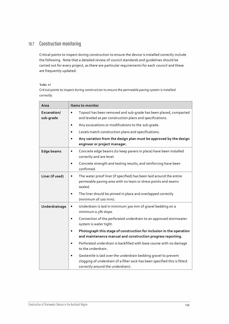
Construction of Stormwater Devices in the Auckland Region 235
18.7 Construction monitoring
Critical points to inspect during construction to ensure the device is installed correctly include
the following. Note that a detailed review of council standards and guidelines should be
carried out for every project, as there are particular requirements for each council and these
are frequently updated.
Table 47
Crit ical points to inspect during construction to ensure the permeable paving system is installed
correctly.
Area Items to monitor
Excavation/
sub-grade
Topsoil has been removed and sub-grade has been placed, compacted
and leveled as per construction plans and specifications.
Any excavations or modifications to the sub-grade.
Levels match construction plans and specifications.
Any variation from the design plan must be approved by the design
engineer or project manager.
Edge beams Concrete edge beams (to keep pavers in place) have been installed
correctly and are level.
Concrete strength and testing results, and reinforcing have been
confirmed.
Liner (if used) The water proof liner (if specified) has been laid around the entire
permeable paving area with no tears or stress points and seams
sealed.
The liner should be pinned in place and overlapped correctly
(minimum of 100 mm).
Underdrainage Underdrain is laid in minimum 300 mm of gravel bedding on a
minimum 0.5% slope.
Connection of the perforated underdrain to an approved stormwater
system is water tight.
Photograph this stage of construction for inclusion in the operation
and maintenance manual and construction progress reporting.
Perforated underdrain is backfilled with base course with no damage
to the underdrain.
Geotextile is laid over the underdrain bedding gravel to prevent
clogging of underdrain (if a filter sock has been specified this is fitte d
correctly around the underdrain).

Construction of Stormwater Devices in the Auckland Region 236
Area Items to monitor
Base course The gravel base course (with minimum 30% voids) is carefully laid over
geotextile to depth specified on construction plan.
The gravel base course must be strong enough to support the site’s
traffic loads (i.e. no scoria) and the depth is dependent on the required
storage volume in the voids.
Bedding
material
Clean, fine grade bedding gravel is laid gently over the base course
(with no compaction) as per paver’s manufacturers and construction
plan specifications.
Bedding material is leveled with a rake or straight edge.
Pavers
Pavers are laid as per manufacturers specifications and are even and
flat with joint material filling all the gaps.
If the area is on a hill pavers must be laid from the lowest point up.
If grass is required between blocks, seeds need to be densely
sown/planted to ensure complete coverage of the entire site. A water
schedule is in place until grass is established.
18.8 Photo gallery – permeable paving
Figure 101
Beachaven Reserve permeable pavement associated with car park spaces. Road stormwater directed
away from the paving to a roadside catchpit. [NSCC]

Construction of Stormwater Devices in the Auckland Region 237
Figure 102
Barry Curt is Park permeable pavement. Note the bare soil around the landscaped margins and sediment
on the asphalt surface, both sources of sediment that could lead to accelerated clogging of the
permeable paving. [MCC]
Figure 103
Birkdale Road permeable paving. [NSCC]

Construction of Stormwater Devices in the Auckland Region 238
Figure 104
ST001 – North Shore Events Centre permeable pavement. [NSCC]
Figure 105
ST001 – North Shore Events Centre permeable pavers (porous paver). [NSCC]
Construction of Stormwater Devices in the Auckland Region 239
Figure 106
Kirkbride Road permeable pavement draining to rain garden.
Figure 107
Permapave resin blocks, Auckland Botanic Gardens. [ARC]

Construction of Stormwater Devices in the Auckland Region 240
Figure 108
Unitec Sports Complex car parking, Gobi block permeable paving.
Figure 109
Permeable paving showing gravel joint material. [NSCC]

Construction of Stormwater Devices in the Auckland Region 241
Figure 110
Permeable paving being laid over gravel basecourse. [NSCC]
18.9 Construction specification example – permeable paving
18.9.1 Site preparation
18.9.1.1 Clearance
Existing trees around the paving site shall be protected and those identified for removal on
the drawings shall be removed. The Contractor shall comply with any consent or District Plan
requirements concerning the preservation, trimming or transplanting of trees, shrubs, etc.
18.9.1.2 Topsoil
The Contractor shall strip the topsoil from all areas to be excavated, filled or otherwise
disturbed due to the construction of the contract works, and stockpile it in an approved
location. The depth of topsoil stripped shall be:
at least 300 mm in farmland, residential property or other cultivated areas; or
at least 150 mm elsewhere; or
the full depth of topsoil where less than the above depths exist.

Construction of Stormwater Devices in the Auckland Region 242
18.9.1.3 Disposal of material and rubbish
All materials arising from site clearance which are surplus to or unsuitable for use in the Works
shall become the property of the Contractor and shall be disposed off the site.
All fences, buildings, structures and encumbrances of any character, except those that are
earmarked for removal by others, upon or within the limits of the site, shall be removed by the
Contractor and disposed of as directed by the Engineer.
18.9.1.4 Site fencing
The work area (excavations, stock-pile areas, etc) shall be adequately fenced to delineate their
extent and to fulfil the Contractor’s obligations of site safety and security, all to the
satisfaction of the Engineer.
18.9.1.5 Disposal of water
Water from either pipe installation, surface drainage of the site, or dewatering of excavations
shall be treated (e.g. passed through a silt fence, settling pond or other treatment) in
accordance with ARC requirements prior to discharge. Once treated to the required level, the
water may be disposed of downstream into the existing water course, the public road
stormwater drain or public foul sewer subject to local council and ARC approval. Where this
cannot be achieved, water from excavations must be removed off-site and disposed of in an
approved manner.
Water from any lubrication system used for pipe installation may not be discharged from the
site without the approval of the Engineer.
18.9.2 Permeable paver installation
18.9.2.1 Sub-grade
The sub-grade material shall be “run of pit” sand, unless otherwise specified or approved by
the Engineer. The suitability of alternatives will need to be demonstrated. The sub-grade
shall be laid in layers not exceeding 150 mm (compacted thickness) and at optimum moisture
content.
The material shall be compacted to the specified California Bearing Ratio (CBR) as measured
with a standard scala penetrometer. Except that the standard of compaction shall not be less
than 95% of the optimum dry density of the material as specified in Test 4.1.1 of NZS
4402:1986 “New Zealand Standard Compaction Test”, or Test 4.1.3 “New Zealand Vibrating
Hammer Compaction Test”.
The entire surface of the completed sub-grade shall be made smooth, firm and uniform, by
blading, grading and rolling, approximating the crossfall required on the final surface.
Compaction shall not continue if the surface shows any signs of excessive weaving or heaving,
until the problem has been resolved.

Construction of Stormwater Devices in the Auckland Region 243
18.9.2.2 Edge beams
Edge beams shall be constructed as per the drawings. Concrete and formwork shall comply
with NZS 3109 “Specification for Concrete Construction” and subsequent amendments.
Concrete supplied to the site shall comp ly with NZS 3108 “Specification for Concrete
Production – Ordinary Grade”.
Sulphate resistant concrete shall be 80% Duracem, 4% microsilica and 16% general purpose
Portland Cement.
Concrete shall be Ordinary Grade of strength 17.5MPa or 20MPa, as shown on the drawings,
with maximum aggregate size 19 mm and slump 100 mm.
Concrete shall be supplied to site as batched ready mixed concrete from an approved supplier.
The Contractor shall keep a delivery record for each batch delivered to site. This shall reco rd
the supplier, date, time, quantity delivered, mix code, specified strength, aggregate size and
slump.
The Contractor shall carry out a slump test on each batch delivered, an d shall allow in his price
for one concrete test cube to be taken, cured and tested for each batch delivered. Concrete
test cubes will be required on the instruction of the Engineer.
Concrete surfaces that will be buried shall be surface finish U1 to NZS 3114.
18.9.2.3 Underdrain and filter cloth
The underdrain shall be installed on top of the sub-grade in the position detailed on the
drawings. The underdrain shall be Novacoil subsoil drain with geotextile shall be laid over the
top to cover the entire area to be paved. The geotextile is to be laid and pinned as per the
manufacturer’s instructions.
An evenly placed 50 mm layer of GAP20 shall be laid along the length of the underdrain.
The Novacoil shall be connected to the existing manhole/catchpits as detailed on the
drawings.
18.9.2.4 Novacoil connection to manholes
When connecting to the existing stormwater manholes, the Novacoil shall be protected from
stress concentration and possible fracture of the pipe at the concrete face by the insertion of a
10 mm thick neoprene strip minimum 100 mm wide wrapped around and cemented to the
pipe and embedded fully in the manhole wall/concrete surround with the outer edge of the
strip at the outer surface of the concrete. There shall be sufficient concrete thickness between
the inner edge of the strip and inner surface of the manhole to ensure water tightn ess (refer
drawings). Care shall be taken to ensure that the neoprene strip is not displaced during
concreting.
In addition to the neoprene strip, a sodium bentonite strip shall be wrapped around and
cemented to the pipe and embedded fully in the manhole wall/concrete surround. Refer
drawings.

Construction of Stormwater Devices in the Auckland Region 244
18.9.2.5 Base course
Material in this layer shall be coarse aggregate, meeting the criteria of clause 3.0: Testing.
This layer shall not be installed until the all previous layers have been completed and approved
by the Engineer.
Samples of base course shall be selected at random and tested to check compliance with
aggregate grading, ratios and compacted permeability.
Permeable aggregates are subject to separation during transport and construction. Care
should be taken to avoid separation occurring. The gravel shall be cleaned, washed, crushed
rock with a minimum of 30% voids.
The base course layers shall be constructed in layers of uniform thickness not exceeding 150
mm. Geotextile shall be installed and pinned over the base course as per the manufacturer’s
instructions.
18.9.2.6 Bedding sand
The bedding sand shall be clean sand or fine gravel spread evenly over the geotextile layer as
per the drawings. The bedding sand shall be levelled using a rake or straight edge – do not
compact the bedding layer.
18.9.2.7 Pavers
The concrete segmental pavers shall be manually laid in accordance with NZS 3116:2002
‘concrete segmental paving’. The pavers shall be installed as per the manufacturer’s
instructions.
The paver shall be a minimum of 80 mm thick and shall comply with the requirements for
application 2, residential driveways, light traffic (NZS 3116, Clause 302 Paver Selection). The
pavement layer shall achieve 95% maximum dry density.
Pavers are to be free of foreign materials before installation and installed in the pattern shown
on the drawings maintaining straight lines. Joints between pavers to be per manufacturers
design. Pavers shall be vibrated into place, dry joint sand swept into joints and vibrated until
full. Do not vibrate with 1 m of the unrestrained edges.
Final elevations shall be checked for conformance to the drawings to the satisfaction of the
Engineer.
18.9.3 Testing
The base course shall be tested for particle size distribution according to NZS 4407, Test 3.8.1
Wet Sieving Test to comply with Table 48:

Construction of Stormwater Devices in the Auckland Region 245
Table 48
Wet sieving test complying percentages.
Sieve aperture Maximum and minimum allowable percentage weight
passing
37.5 100
19.0 60-75
4.75 3-18
2.36 0-5

Construction of Stormwater Devices in the Auckland Region 246
19 Rain Tanks
19.1 Introduction
Rain tanks are used in rural areas for household water supply but are not as prevalent in urban
areas. This is mainly due to the public health issues associated with unfiltered tank water. In
previous years rain tanks have been discouraged or require permits if there is a mains potable
water supply.
However with the advent of a more sustainable approach to stormwater management and
particularly water supply rationing, rain water tanks are increasing in popularity for non -
potable use and rainwater detention. Rain tanks can be used for rainfall detention, water
harvesting or a combination of both (dual purpose tanks).
19.2 Device description
Rain tanks collect rainwater that runs off hard surfaces (inflow) free of substantial amounts of
sediment and debris such as roofs and car parks via a pipe network. The rain tank then stores
the rainwater temporarily to reduce stormwater runoff flows and/or permanently to be used
as a non-potable water supply (non-drinking water uses such as toilet, laundry and outdoor
uses). Rain tanks provide some minimal stormwater treatment by removing contaminants
through settlement of sediment at the base of the tank; however they are primarily used for
stormwater re-use or attenuating stormwater run-off. Rain tanks can be installed either
above or below ground.
Harvesting rain tanks should collect roof runoff only, whereas detention rain tanks are suitable
for all sources of runoff. For all rain tanks, some form of sediment control is recommended to
reduce potential clogging issues within the system.
Rain tanks are common in rural and semi-rural areas not yet serviced by a mains water supply.

Construction of Stormwater Devices in the Auckland Region 247
Figure 111
Typical rain tank components.

Construction of Stormwater Devices in the Auckland Region 248
Table 49
Key components of rain tanks.
Device component Description
Collection system
and pre-treatment
Collection systems can be gutter systems, kerb and channeling (if
collecting runoff from ground surfaces such as car parking areas), or
traditional stormwater piping. The collection system may be fitted
with:
Leaf guards and debris diverters.
First flush diverters (to divert the ‘dirty’ initial runoff).
Insect screens.
Sediment traps (for non-roof hard surfaces such as parking
areas).
Controlled tank inlets (to prevent stirring up of bottom
sediments).
Tank Above or below ground; concrete, steel or polyethylene; and
specifically designed tanks (i.e. for architectural purposes).
Plumbing Piped systems that supply non-potable water to the household,
including:
Pumps (in most cases).
Water supply outlet (where water exits the tank).
Backup water supply connection (connection to the existing
reticulated water supply that tops up the tank during periods of
low rainfall, usually activated by a float switch).
Filtration (a filter that removes any debris from the runoff/tank
but is not normally required).
Overflow system Piped overflow from tank that usually discharges to the local
stormwater system (often 80-100 mm in diameter), when the tank is
full.
Orifice Small diameter outlet which restricts the outflow from the tank. Only
used where detention is provided.
There are three different types of rain tank: detention, single-purpose and dual-purpose:

Construction of Stormwater Devices in the Auckland Region 249
Figure 112
Detention tank schematic (Source: NSCC, 2008. Raintank Guidelines).
Detention tanks
Reduces peak storm water runoff flows by storing rainwater from the roof and other hard
surfaces (parking areas, etc) and slowly releasing the rainwater through a small diameter
orifice.
Detention tanks have one inlet pipe which transports the collected water to the tank. The
tanks have two outlet pipes. One outlet pipe is a small diameter orifice be tween 10 mm to 35
mm. This outlet is located near the bottom of the tank, and slowly releases the water from
the tank into the local stormwater system.
The second outlet is a large diameter overflow pipe near the top of the tank. It is usually
between 80 to 100 mm in diameter and connected into the local stormwater system. When
the tank is full, additional runoff overflows to this pipe and is discharged to the local
stormwater system.

Construction of Stormwater Devices in the Auckland Region 250
Figure 113
Single purpose rain tank schematic (Source: NSCC, 2008. Raintank Guidelines).
Single-purpose rain tanks
Provides a non-potable water supply. Collects rainwater mostly from roof areas and supplies
rainwater for non-potable (non-drinking) household uses (i.e. toilet, laundry and outdoor use).
They are less frequently used to collect runoff from ground surfaces such as parking areas
because the runoff includes pollutants/sediment, which are not suitable for household non -
potable water use. Additional pre-treatment and/or post-treatment may be required for
tanks collecting runoff from ground surfaces.
Single-purpose rain tanks have one inlet pipe which transports the collected water to the
tank. The tank has two outlet pipes. The tank’s first outlet pipe is a large diameter (80 –
100 mm diameter) overflow pipe near the top of the tank.
The second outlet pipe is a small (up to 25 mm) water pipe located near the bottom of the
tank which feeds the rainwater to a pump and then to household non-potable water use. All
of the water stored in the tank is used for non-potable water use.

Construction of Stormwater Devices in the Auckland Region 251
Figure 114
Dual purpose rain tank schematic (Source: NSCC, 2008. Raintank Guidelines).
Dual-purpose rain tanks
Provides a non-potable water supply and reduces peak stormwater runoff flows. Collects
water from roof areas only. Combines collection for non-potable use and detention into one
tank by locating the small diameter orifice part way up the side of the tank. The volume
below the orifice is ‘permanently’ stored for use as household non-potable water and volume
above the small diameter orifice is ‘temporarily’ stored and released through the orifice
during and after each rainfall event.
Dual-purpose rain tanks comprise one inlet which transports the collected water to the tank,
and three outlet pipes. One of the outlet pipes is a small diameter orifice (between 10 mm to
35 mm) located midway down the side of the tank. This outlet slowly releases the top section
of water (detention) from the tank into the local stormwater system.
The second outlet pipe is a small (up to 25 mm) water pipe located near the bottom of the
tank which feeds the rainwater to a pump and then to household non-potable water use.
The third outlet pipe is a large diameter (80 to 100 mm diameter) overflow pipe near the top
of the tank.

Construction of Stormwater Devices in the Auckland Region 252
19.3 Guideline documents
Table 50
Guidelines relat ing part icularly to rain tanks include:
Publisher Title Description
ARC TP90 Erosion and Sediment
Control Guidelines for Land
Disturbing Activities in the
Auckland Region
These guidelines outline the principals of
erosion and sediment control and control
measures that should be used.
ARC TP124 Low Impact Design
Manual for the Auckland
Region
Approaches to site design and development
from a stormwater management context,
primarily applicable for residential land
development.
NSCC Stormwater Management
Practice Note NSC 05:
Residential Single Purpose
Rain Tanks
Practice notes giving general information on
the minimum design requirements and
maintenance of single purpose rain tanks.
NSCC Stormwater Management
Practice Note NSC 06: Dual
Purpose Rain Tanks for
Residential Applications
Practice notes giving general information on
the minimum design requirements and
maintenance of rain tanks for residential
applications.
NSCC Stormwater Management
Practice Note NSC 07:
Detention Tanks
Practice notes giving general information on
the minimum design requirements and
maintenance of detention tanks.
NSCC Stormwater Management
Practice Note NSC 08: Single
Purpose Rain Tanks for Non-
Residential Applications
Practice note developed to give general
information on the minimum design
requirements and maintenance of single-
purpose tanks for non-residential activities.
NSCC Stormwater Management
Practice Note NSC 09: Dual
Purpose Rain Tanks for Non-
Residential Applications
Practice note developed to give general
information on the minimum design
requirements and maintenance of dual-
purpose tanks for non-residential activities.
NSCC LB102 On Site Stormwater
Mitigation
Practice note to assist choice of appropriate,
cost effective stormwater management
solutions and explains how to select pre-
approved solutions using a stormwater
migration factor or proposal alternative
technologies.
NSCC LB103 Rainwater Harvesting Practice note to assist with the design of
rainwater tanks in the Long Bay area.

Construction of Stormwater Devices in the Auckland Region 253
Publisher Title Description
NSCC LB107 Long Bay Water Supply
Systems
Practice note to be used in conjunction with
NSCC Infrastructure design standards for the
design and construction of the Long Bay water
supply system.
NSCC LB110 Other Technologies Practice note based on the ARC’s TP10,
describing requirements for alternative
technologies to meet the Long Bay water
quality and quantity management objectives.
NSCC LB209 Worked Examples Some worked examples showing the steps for
design of stormwater management devices
such as filter strips and rain gardens.
NSCC North Shore City Raintank
Guidelines
Provides guidance on different types of rain
tanks, layouts, considerations, etc.
NZWWA On Site Stormwater
Management Guideline
Provides guidance on the design of on-site
stormwater management devices for the
majority of applications in New Zealand.
WCC Stormwater Solutions for
Residential Sites
Document providing guidance on
management practices applicable to
developments on individual residential lots
(<1000 m²). For use by engineers and
applicants for stormwater control building
permits for developments of this size.
19.4 Standards and technical documents
Table 51
Below is a non-exhaustive list of some of the more applicable standards and technical docum ents that
relate to rain tanks:
Title Description
AS/NZS 1254:2002
PVC Pipes and Fittings
for Stormwater and
Surface Water
Applications
Specifies requirements for PVC pipes and fittings for conveyance
of stormwater or surface water. The Standard includes
requirements for both plain and structured wall pipes and fittings.
AS/NZS 1260:2009
PVC-U Pipes and
Fittings For Drain, Waste
and Vent Application
Specifies requirements for uPVC pipes and fittings for sewer,
drain, waste and vent applications above-ground or below ground
and intended to be used where the pipeline is operating under
gravity flow and the operating pressure is low.

Construction of Stormwater Devices in the Auckland Region 254
Title Description
NZS 3101.1&2:2006
Concrete Structures
Standard
The design of concrete structures, specifies minimum
requirements for the design of reinforced and pre-stressed
concrete structures.
NZS 3104:2003
Specification for
Concrete Production
Prescribes minimum requirements for the production of fresh
concrete.
NZS 3109:1997
Concrete Construction
Provides minimum requirements for the construction of
reinforced concrete, unreinforced concrete, pre-stressed concrete
or a combination, in elements of any building or civil engineering
structure.
NZS 3114:1987
Specification for
Concrete Surface
Finishes
Categorizes by means of description and illustration various
classes of surface finish of concrete obtained off-the-form, by
exposed aggregate and on floors, exterior pavements and inverts.
NZS 7643:1979
Code of Practice for the
Installation of
Unplaticised PVC Pipe
Systems
Sets out the methods of installation of uPVC pipelines above or
below ground for pressure and non-pressure applications using
pipe and fittings complying with NZS 7641, NZS 7642 and NZS
7649.
New Zealand Drinking
Water Standards 2005
The DWSNZ2005 details how to assess the quality and safety of
drinking water using the revised water quality standards and
compliance criteria. The drinking water standards apply to
drinking water, that is, water intended to be used for human
consumption, food preparation, utensil washing, oral or personal
hygiene.
Building Code Covers the requirements under the Building Act (1991).
19.5 Construction considerations
Rain tanks that do not have a pumping system installed or connection to a mains supply are
normally very easy to install. Some of key considerations for the installation of tanks include
the following:
19.5.1 Aesthetics
Consider the visual impacts of the building platform and tank for aesthetic reasons. The tanks
can be supplied in a variety of colours and shapes, which will assist to blend in with the
surrounding environment or fit beneath decks or the house.
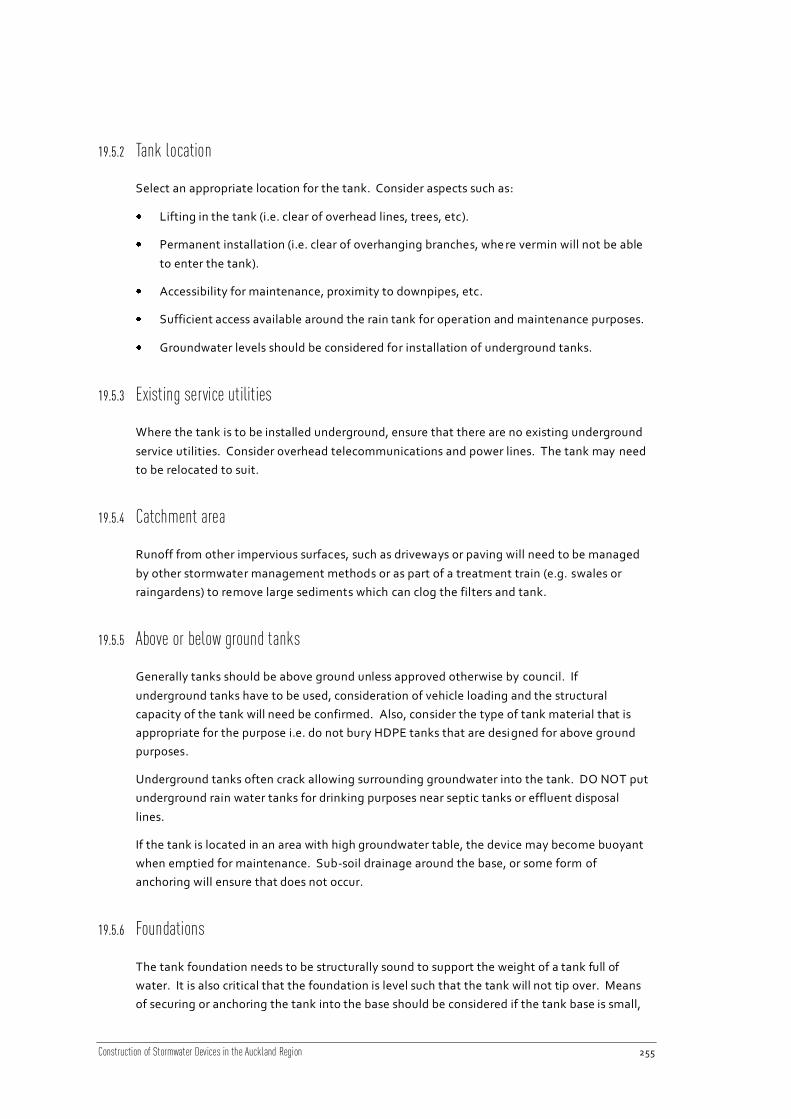
Construction of Stormwater Devices in the Auckland Region 255
19.5.2 Tank location
Select an appropriate location for the tank. Consider aspects such as:
Lifting in the tank (i.e. clear of overhead lines, trees, etc).
Permanent installation (i.e. clear of overhanging branches, whe re vermin will not be able
to enter the tank).
Accessibility for maintenance, proximity to downpipes, etc.
Sufficient access available around the rain tank for operation and maintenance purposes.
Groundwater levels should be considered for installation of underground tanks.
19.5.3 Existing service utilities
Where the tank is to be installed underground, ensure that there are no existing underground
service utilities. Consider overhead telecommunications and power lines. The tank may need
to be relocated to suit.
19.5.4 Catchment area
Runoff from other impervious surfaces, such as driveways or paving will need to be managed
by other stormwater management methods or as part of a treatment train (e.g. swales or
raingardens) to remove large sediments which can clog the filters and tank.
19.5.5 Above or below ground tanks
Generally tanks should be above ground unless approved otherwise by council. If
underground tanks have to be used, consideration of vehicle loading and the structural
capacity of the tank will need be confirmed. Also, consider the type of tank material that is
appropriate for the purpose i.e. do not bury HDPE tanks that are designed for above ground
purposes.
Underground tanks often crack allowing surrounding groundwater into the tank. DO NOT put
underground rain water tanks for drinking purposes near septic tanks or effluent disposal
lines.
If the tank is located in an area with high groundwater table, the device may become buoyant
when emptied for maintenance. Sub-soil drainage around the base, or some form of
anchoring will ensure that does not occur.
19.5.6 Foundations
The tank foundation needs to be structurally sound to support the weight of a tank full of
water. It is also critical that the foundation is level such that the tank will not tip over. Means
of securing or anchoring the tank into the base should be considered if the tank base is small,

Construction of Stormwater Devices in the Auckland Region 256
and tank sides high. A ring beam around the base of the tank, or struts to support the tank
can be used in this situation.
Where the tank is on a sloping site, specialist geotechnical input should be used for retaining
walls and foundations.
19.5.7 Inlet and outlet levels
Prior to installing holes in the tank for the inlet and outlet pipes (if not pre -drilled), confirm the
inlet and outlet levels. This is an important aspect as these vary considerably depending on
the type of system that will be operating i.e. detention tanks, single-purpose tanks, and dual-
purpose tanks.
19.5.8 First flush diverters
Normally the first flush will contain the majority of contaminants from the ro of area. Where
practicable, it is preferable to prevent this entering the tank and indeed where tanks are used
for drinking water this is essential. First flush and debris diverters can be installed to achieve
this. Sediment traps and controlled tank inlets can also be used for this purpose.
19.5.9 Insect screens
The tank should be protected from leaves, other debris and vermin entering the tank.
Consider the installation of leaf guards and insect screens. A fine mesh should be used to
prevent entry of mosquitoes.
19.5.10 Access hatches
All tanks should have hatches which are easy to access i.e. consider overhead clearance if
under buildings/structures, height of the tank, etc. These should be fully secure and should be
lockable.
Where possible fully removable hatches should be specified as this will make maintenance
easier (when the tank is cleaned out). Ensure that these are lightweight enough to be lifted
and/or removed (consider that most will be accessed by a ladder).
Access hatches are provided for access to the tank for inspection and maintenance purposes
but under no circumstances should personnel (except by qualified and experienced personnel)
enter the tank as it is a CONFINED SPACE.
19.5.11 Outlet orifices
Note that detention tanks often require the installation of a small diameter outlet to act as an
orifice. These can often become blocked and consideration should be made during
installation in regards to accessing the outlet for cleaning.

Construction of Stormwater Devices in the Auckland Region 257
19.5.12 Connections to water supply and plumbing
In many situations a substantial amount of plumbing from the tank to the existing water
supply, or the installation of a pump, floats and control box will be required. It is important to
remember that a building consent is required under the Building Code and that this work can
only be carried out by a certified plumber and electrician.
Where pumps are required, consideration of power supply to the site is needed. Safety
considerations should given to electrical safety where electrical supply for pumps is required
19.5.13 Overflows
The location of the overflow from tanks fitted with overflow devices should be carefully
considered. This is particularly important in urban areas where incorrect discharge may cause
localised flooding on neighbouring properties.
In rural areas, the overflow should be clear of existing infrastructure such as septic tanks and
effluent disposal lines.
19.6 Construction specifications
Table 52
The following aspects should be specified when constructing a rain tank:
Area Items to include
Collection
and pre-
treatment
system
• Specify the type, size and material for the collection system. If
included, also specify the size and type of additional fittings:
o Leaf guards and debris diverters.
o First flush diverters (to divert the ‘dirty’ initial runoff that falls on the
roof).
o Fine mesh insect (or vector) screens.
o Sediment traps.
o Controlled tank inlets.
Tank
foundation (if
required)
• Specify the sub-base material, concrete strength, depth and reinforcing
required for the concrete foundation. If a blinding layer is necessary,
specify the grade and depth of material required.
Tank • Specify the volume of the tank to be installed and required tank
material.
• Specify tank dimensions and height above ground.
Plumbing • Specify in detail the following (where included):
o Pumps (brand, pump rate and head required).

Construction of Stormwater Devices in the Auckland Region 258
Area Items to include
o Water supply outlet diameter and any additional pipe work.
o If a backup water supply connection is required and where backup
water would be supplied.
o Filter size and type.
Overflow
system
• Specify the type of overflow system. Normally this includes the pipe
diameter and material required.
Orifice • If an orifice outlet is included, the pipe diameter and material should be
specified.
Example specifications are shown in Section 19.9. These cover some of the typical aspects for
construction of rain tanks, but exclude particulars such as site establishment, health and
safety, testing, materials, and reinstatement, as these differ greatly depending on the
application.
These example specifications do not constitute a full specification for the construction of any
rain tank, and should be used as a ‘starter specification’ for guidance only. Each rain tank will
be site specific and require careful consideration to ensure that all aspects of constructio n are
covered.
19.7 Construction monitoring
Critical points to inspect during construction to ensure the device is installed correctly are
listed in Table 53 It is a good idea to keep a photographic diary of construction activities for
the operation and maintenance manual and to assist in any future troubleshooting of issues.
Table 53
Crit ical points to inspect during construction of a rain tank:
Area Items to monitor
Excavation/
foundations
• Check levels match construction plans and specifications.
• Any variation from the design plan may change the levels and
function of the rain tank separator and must be approved by the
design engineer or project manager.
• Good founding material present and foundation is level.
• Note any groundwater interaction.

Construction of Stormwater Devices in the Auckland Region 259
Area Items to monitor
Plumbing • Make sure a registered plumber and electrician are used for all plumbing
and electrical work. Check that all plumbing and electrical work is
certified as required by the Building Code.
• Check elevations of the different piping details checked to ensure they
perform as per specifications.
• Make sure all fixtures are water tight and there are no leaks on
completion.
• Ensure no backflows occur in the system.
Overflow • Rain tank overflow is NOT connected to the wastewater network (this is
illegal).
Signage • All taps and outlets supplying non-potable water have required symbol
and wording “Not Suitable for Drinking”.
19.8 Photo gallery – rain tanks
Figure 115
Maybury Street rain tank.

Construction of Stormwater Devices in the Auckland Region 260
Figure 116
Glencourt Place rain tank.
Figure 117
Waitakere Hospital rain tanks.

Construction of Stormwater Devices in the Auckland Region 261
Figure 118
Waitakere Hospital rain tanks.
Figure 119
Low impact urban design incorporating rain tanks.

Construction of Stormwater Devices in the Auckland Region 262
Figure 120
Glencourt Place rain tank. Note good solid foundation.
Figure 121
Glencourt Place rain tanks.

Construction of Stormwater Devices in the Auckland Region 263
Figure 122
Glencourt Place rain tank on unstable foundation, tank is now leaning.
Figure 123
Glencourt Place rain tank.

Construction of Stormwater Devices in the Auckland Region 264
Figure 124
Glencourt Place rain tank with overhanging branches.
Figure 125
Glencourt Place rain tank with diff icult access.

Construction of Stormwater Devices in the Auckland Region 265
Figure 126
Glencourt Place rain tank.
Figure 127
Glencourt Place rain tank.
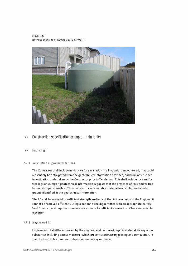
Construction of Stormwater Devices in the Auckland Region 266
Figure 128
Royal Road rain tank part ially buried. [WCC]
19.9 Construction specification example – rain tanks
19.9.1 Excavation
19.9.1.1 Verification of ground conditions
The Contractor shall include in his price for excavation in all material s encountered, that could
reasonably be anticipated from the geotechnical information provided, and from any further
investigation undertaken by the Contractor prior to Tendering. This shall include rock and/or
tree logs or stumps if geotechnical information suggests that the presence of rock and/or tree
logs or stumps is possible. This shall also include variable material in any filled and alluvium
ground identified in the geotechnical information.
"Rock" shall be material of sufficient strength and extent that in the opinion of the Engineer it
cannot be removed efficiently using a 20 tonne size digger fitted with an appropriate narrow
"rock" bucket, and requires more intensive means for efficient excavation. Check water table
elevation.
19.9.1.2 Engineered fill
Engineered fill shall be approved by the engineer and be free of organic material, or any other
substances including excess moisture, which prevents satisfactory placing and compaction. It
shall be free of clay lumps and stones retain on a 75 mm sieve.

Construction of Stormwater Devices in the Auckland Region 267
19.9.1.3 Over excavation
If the Contractor takes out any material to a greater depth or width than shown on the
drawings or specified, without the instruction of the Engineer the extra depth or width shall be
filled either with concrete, approved hardfill, or excavated material as nominated by the
Engineer, and thoroughly compacted without any extra payment.
19.9.1.4 Stockpiling and removal of excavated material
All excavated material required for fill shall be properly stockpiled with steep faces to allow
maximum drainage in an approved location inside the working area. Stockpiled material shall
be covered with geotextile or polythene if rain is forecast.
Stockpiled material which deteriorates and becomes unsuitable because of avoidable delays,
poor storage arrangements or other circumstances within the Contractor's control shall be
replaced with suitable material at the Contractor's own cost.
Where material is stockpiled off site the proposed stockpile site shall be submitted to the
Engineer for Approval.
19.9.1.5 Support
The Contractor shall support the sides of excavations with suitable shoring to comply with all
safety requirements and so that excessive widening of the excavation is avoided. Support may
be provided by use of shields, timber, sheet piling or other shoring systems, subject always to
the Engineer's agreement of the proposed method. Any such agreement given by the
Engineer shall not absolve the Contractor of this responsibility to minimise the area disturbed
by the works and to make the site safe.
Timbering or sheet piling shall (where possible), be drawn up and removed as the concreting
or backfilling progresses so as to ensure that all voids at the side, or in other places, are filled
as the contract works advance.
19.9.1.6 Excavation support left in place
Where the Engineer considers it necessary for shoring to be left permanently in the work he
may so order in writing, in which case payment will be made at the rate of half the new price
of such timber or sheet piles.
All shoring left in place shall be kept clear of the permanent contract works. The Engineer
may direct that shoring left in place be cut off at any specified level in which case payment will
be made only for the portion remaining in the ground.
The fact of any shoring being left in place, or not being left in place, shall not relieve the
Contractor from any responsibility for any settlement or other damage caused by his
operations. Backfill to all excavations shall meet the strength and compaction requirements
of the specification, and the reinstatement details given on the drawings.

Construction of Stormwater Devices in the Auckland Region 268
19.9.2 Foundation
Shear strength testing of the bedding material for the foundation may be required by the
Engineer after excavation if the material is significantly different to that expected from the
geotechnical investigations provided.
Excavation for the foundations shall be 300 mm below the invert level of the rain tank. The
founding material will consist of a 300 mm layer of GAP7 bedding. The rain tank will rest on
top of this bedding.
The foundations are to be laid to the levels indicated in the drawings to the satisfaction of the
Engineer.
19.9.3 Tank installation
All plumbing and drainage work to the Building Act 2004 and the NZ Building Code.
19.9.3.1 Tank material
The tank material shall be polyethylene, complying with AS/NZS 4766:2006 “Polyethyle ne
Storage Tanks for Water and Chemicals”, or concrete complying with NZS 3106: 2009 “Code
of practice for concrete structures for the storage of liquids”.
19.9.3.2 Tank installation
The tank shall be installed to the manufacturer’s instructions.
19.9.3.3 Buoyancy
The groundwater levels in the area shall be determined and the completed structure shall be
checked for buoyancy under the range of operating conditions including when the tank is
empty.
19.9.3.4 Plumbing and piping
The coarse litter screen (leaf screen) shall be installed in the location indicated on the
drawings to the manufacturer’s specifications.
The existing spouting shall be connected to the rain water tank by a PVC pipe as detailed on
the drawings. PVC pipes shall be manufactured in accordance with AS/NZS 1260 “PV C Pipes
and Fittings” and installed in accordance with NZS 7643 “Installing uPVC Pipes”.
Connection to the mains for top up shall be as detailed on the drawings and shall comply with
the local council’s standards for connection to water mains and the NZ Building Code.
The tank overflow connection to the stormwater system shall comply with NZS4404:2004 and
as per the local council’s standards.

Construction of Stormwater Devices in the Auckland Region 269
19.9.3.5 First flush diversion
The first flush diverter shall be installed as detailed on the drawings as per the manufacture r’s
instructions.
19.9.3.6 Pumps
Pumps be installed in accordance with manufacturer’s instructions and shall be plumbed as
per NZS 3500.5:2000 by a certified and registered plumber. All electrical work shall be
completed by a registered electrician. Pump and enclosure shall be of silent type.
Mains water feed shall be controlled by a float operated shut off ball valve.
19.9.3.7 Backflow prevention
A non-return valve shall be installed as detailed on the drawings for backflow prevention as
per AS3500.1.
19.9.3.8 Access hatch
The access hatch shall be watertight, lockable and finish flush with the ground surface as
detailed on the drawings.
19.9.3.9 Labeling of pipes
Labelling of pipes and fittings shall comply with NZS 3500.5:2000, clause 2.16.6 – coloured
lilac in accordance with AS 2700 colour code P23 (for greywater). All non-potable water
supply outlets shall be clearly and permanently labelled “CAUTION NOT FOR DRINKING”.
Pipes shall be labelled every 500 mm.
19.9.4 Testing
The system shall be tested to ensure the pump works, the backup water supply comes on at
the correct time and that all surfaces drain to the tank that are supposed to and that the
overflow pipe goes to the stormwater system. This Engineer shall verify that the system is
operating correctly before sign-off.

Construction of Stormwater Devices in the Auckland Region 270
20 Living Roofs
20.1 Introduction
Living roofs are gaining in popularity, with property owners either modifying existing
buildings (retrofitting) or including them at the outset of design for new buildings. Living
roofs are also referred to as green roofs, eco-roofs, vegetated roofs or roof gardens. Living
roofs can be designed to assist in a building’s stormwater management, air quality, building
insulation, roof longevity and reduction of the heat island effect.
20.2 Device description
Living roofs are built on top of a human-made structure (e.g. house, office building, or
underground car park) and can be located below, at, or above ground. Living roofs have been
categorised into three basic types: extensive, semi-extensive, or intensive, depending on their
substrate depth, design characteristics and core purpose. Table 54 provides definitions
targeted to a stormwater engineering audience from an international task committee on
living roofs for stormwater control, which falls under the umbrella organisation of the
American Society of Civil Engineers (ASCE).
The key components of a living roof system are presented in Figure 129 and described in Table
55.
Table 54
Broad categorisation of living roof systems
Living Roof
Type
Description1
Extensive Low profile with thinner layers (drainage, substrate, and plants) than
semi-extensive and intensive living roofs
Low growing plants are established in 20–150 mm of substrate
Usually less expensive and lower maintenance when compared to other
types of living roofs
Roof structural requirements are lower than other living roof types, with
saturated weights reported from 70–170 kg m-2
Thin substrate depth limits how much water can be retained in the
system, and hence the diversity and height of plants that can be grown
in the absence of irrigation
1 For more detail, see Fassman, E., Simcock, R., & Voyde, E. (2010). Extensive Green Roofs for Stormwater Management: Part 1
Design and Construction. Auckland: Prepared by Uniservies for Auckland Regional Council. Auckland Regional Council Technical Report 2010/017.

Construction of Stormwater Devices in the Auckland Region 271
Living Roof
Type
Description1
Generally not meant to support foot traffic, other than for occasional
maintenance
Focus on function over form
Semi-
extensive
Designed to be low maintenance, but with deeper layers (drainage,
substrate, and plants) than extensive roofs but not as deep as intensive
roofs
Typical substrate layers range from 100–200 mm
Larger variety of plants can grow on this roof type when compared to an
extensive roof
Irrigation is typically infrequent or absent
Provide function plus a wider plant biodiversity, but are not typically for
occupied spaces
Intensive Have the deepest layers (drainage, substrate, and plants) and a wider
plant variety, including herbaceous plants to shrubs or trees
Substrate is typically >200 mm, which promotes deeper potential root
depth, and hence accommodates a wider height and variety of plant
species
Associated high saturated weight (300–1000 kg m-2
) requires significant
structural support for the roof
Regular irrigation is usually a required design element
Many intensive roofs are designed to be at least partially accessible,
hence design emphasises form and accessibility
Rooftop
Garden
Accessible areas on the roof with containerised plants instead of layers
of membranes and growth media that are installed directly on the roof
deck
May sometimes be considered intensive living roofs
Usually irrigated, where aesthetic requirements are high or particularly
important

Construction of Stormwater Devices in the Auckland Region 272
Figure 129
Typical living roof.
Table 55
Key components of a living roof system.
Device
component
Description2
Plants Species selected to withstand extreme climatic conditions including solar
radiation, wind, drought, and rain. The primary role of the vegetation is to
ensure the surface of the substrate is stable – resistant to rain, wind and
animals. Stems and leaves physically protect the surface from impact while
roots bind and hold the substrate in place. Vegetation also reduces
absorption of solar radiation and provides stormwater attenuation volume
by direct interception of rainfall and through uptake of water from the
substrate, then release to the atmosphere via evapotranspiration.
Growing
media/
substrate
Usually composed of 80-90% light weight aggregate (eg. pumice or zeolite)
and up to 20% organic material. The growing medium should be stable
(resistant to rot, shrinkage etc) and well draining to promote ongoing plant
health and structural integrity. The use of fertiliser shall be minimised,
however if necessary shall only be applied as per landscaping plan. The
growth medium supports plants both physically and nutritionally, stores
precipitation up to field capacity, extends flow path to reduce runoff
velocity, and provides thermal mass/insulation.
2 For more detail, see Fassman, E., Simcock, R., & Voyde, E. (2010). Extensive Green Roofs for Stormwater Management: Part 1
Design and Construction. Auckland: Prepared by Uniservies for Auckland Regional Council. Auckland Regional Council Technical Report 2010/017.

Construction of Stormwater Devices in the Auckland Region 273
Device
component
Description2
Root barrier/
geotextile
material
The geotextile (filter fabric) physically supports the substrate, separating it
from the drainage layer and preventing migration of substrate fines, to
maintain a free-flowing drainage layer. It can be either a separate layer, or
attached to a commercially available drainage layer.
A root barrier is required to prevent root penetration into the waterproof
membrane. There are a number of options for this including chemical
compositions in the water proof membrane or geotextile, or a laminated
layer.
Some root barriers contain chemicals toxic to fish – these should not be used
for living roof applications.
Drainage
layer
The drainage layer provides free drainage for rainfall in excess of the system
storage capacity and provides air circulation for plant roots. When using an
aggregate drainage layer, the drainage layer should extend to the surface
around the roof for a width of ≥200 mm. When using a drainage mat, a
gravel edge should be included, extending from the drainage mat to the
surface, around the perimeter of the living roof (and around any protrusions)
for a width of ≥200 mm. This provides additional drainage, fire control and a
visual cue for maintenance access.
Insulation
layer
An optional insulation layer may be included in the living roof design.
Waterproof
membrane
At least a double-ply waterproofing membrane of high quality is strongly
recommended. Alternatively, a purpose-made living roof heavy-duty single
ply membrane with felt layer can be used. Care must be taken during
installation to prevent any damage to the waterproof membrane (by
footwear, installation tools etc). Particular care must also be taken around
protrusions/penetrations (roof vents, air-conditioning units etc), typical
waterproofing problem areas. It is recommended to install gravel edging
around protrusions for protection and easy identification for maintenance.
Outlet Excess water in the drainage material is directed to the outlet. Access is
required for regular maintenance; gravel edging should be installed around
the outlet for ease of identification and access.
20.2.1 Living roof functions
Living roofs reduce the overall impervious coverage of a site, which results in a number of
benefits. In a stormwater management context, living roof systems provide volume reduction
and peak flow attenuation. By converting a usually impervious roof into a permeab le area the
volume of stormwater reaching the outlet during a rainfall event is greatly reduced compared
to that from a conventional rooftop. Water is intercepted by the vegetation, stored within the
porous substrate and returned to the atmosphere via evapotranspiration. In addition, the
path water must take through the living roof system to exit the rooftop results in greatly

Construction of Stormwater Devices in the Auckland Region 274
reduced peak flow rates. Additional environmental, economic, amenity and aesthetic benefits
are also provided by living roof systems:
Reduced energy consumption
o Enhance building insulation (when dry) and thermal mass (when wet)
o Improve air conditioning efficiency and reduce operational cost w here vents are
located above the vegetation, as intake air temperature is cooler than ambien t air
Extend the useful life of a roof surface by protecting it from damaging UV rays which
cause mechanical breakdown
Mitigate the “urban heat island effect” (i.e. lower ambient temperatures)
o Reduce the amount of solar energy absorbed by building materials
o Create a cooling microclimate by evapotranspiration
o Reduce reflected heat
Create urban habitat
o Mitigate removal of habitat from modifying existing land use
o Provide “green corridors”
Absorb and filter airborne pollutants, including dust, while releasing oxygen
Reduce sound/noise transmission
Provide amenity value as a recreational space
Provide aesthetic value and/or blend a building into a sensitive landscape.
The relative degree of each benefit from an individual living roof varies dependant on system
configuration (substrate depth, composition, and vegetation characteristics).
20.3 Guideline documents
Guidelines relating particularly to living roofs are included in Table 56. Note that a detailed
review of council standards and guidelines should be carried out for every project, as there are
particular requirements for each council and these are frequently updated.

Construction of Stormwater Devices in the Auckland Region 275
Table 56
Guideline documents relat ing to living roofs.
Publisher Title Description
ARC TP124 Low Impact
Design Manual for the
Auckland Region
Approaches to site design and development from a
stormwater management context, primarily
applicable for residential land development.
ARC TR2010/017 Extensive
Green (Living) Roofs for
Stormwater Mitigation:
Part 1 Design and
Construction
Report documenting four years of research into
developing green roof design specifically for
stormwater management. The research project
centres around design and retrofit of an extensive
green roof constructed on the roof of the UoA Faculty
of Engineering building
ARC TR2010/018 Extensive
Green (Living) Roofs for
Stormwater Mitigation:
Part 2 Performance
Monitoring
Report documenting performance monitoring of up to
five years of the extensive living roof constructed on
the roof of the UoA Faculty of Engineering, the four
“mini” roofs at Landcare research, the Waitakere City
Civic Centre and the Auckland Botanic gardens living
roofs.
NSCC LB102 On Site
Stormwater Mitigation
Practice note to assist choice of appropriate, cost
effective stormwater management solutions and
explains how to select pre-approved solutions using a
stormwater migration factor or proposal alternative
technologies.
NSCC LB109 Primary and
Secondary Stormwater
Systems
Practice note for design of primary and secondary
overland flowpaths.
NSCC LB201 Minimising
Impervious Areas
Practice note providing ideas for minimising
impervious areas.
NSCC Stormwater
Management Practice
Note NSC 12: Green
Roofs
Practice note with information provided specifically
on most aspects of living roofs.
NZWWA On Site Stormwater
Management Guideline
Provides guidance on the design of on-site
stormwater management devices for the majority of
applications in New Zealand.
WCC Stormwater Solutions
for Residential Sites
Document providing guidance on management
practices applicable to developments on individual
residential lots (<1000 m²). For use by engineers and
applicants for stormwater control building permits for
developments of this size.

Construction of Stormwater Devices in the Auckland Region 276
20.4 Standards and technical documents
Table 57
Below is a non-exhaustive list of some of the more applicable standards and technical documents that
relate to living roofs:
Title Description
AS/NZS 2566.2:2002
Buried Flexible Pipelines -
Installation
Specifies requirements for the installation, field testing and
commissioning of buried flexible pipelines with structural design
in accordance with AS/NZS 2566.1.
AS/NZS 3750.10:1994
Paints for Steel Structures
Covers paints for steel structures – Full gloss epoxy (two-pack).
ASTM E2396-11 Standard Test Method for Saturated Water Permeability of
Granular Drainage Media [Falling-Head Method] for Vegetative
(Green) Roof Systems
ASTM E2397-11 Standard Practice for Determination of Dead Loads and Live
Loads Associated with Vegetative (Green) Roof Systems
ASTM E2398-11 Standard Test Method for Water Capture and Media Retention
of Geocomposite Drain Layers for Vegetative (Green) Roof
Systems
ASTM E2399-11 Standard Test Method for Maximum Media Density for Dead
Load Analysis of Vegetative (Green) Roof Systems
ASTM E2400-06 Standard Guide for Selection, Installation, and Maintenance of
Plants for Green Roof Systems
FLL 2008 Guidelines for the Planning, Construction and Maintenance of
Green Roofing: Green Roofing Guideline
NZS 3104:2003
Specification for Concrete
Production
Prescribes minimum requirements for the production of fresh
concrete.
NZS 3109:1997
Concrete Construction
Provides minimum requirements for the construction of
reinforced concrete, unreinforced concrete, pre-stressed
concrete or a combination, in elements of any building or civil
engineering structure.
NZS 3114:1987
Specification for Concrete
Surface Finishes
Categorizes by means of description and illustration various
classes of surface finish of concrete obtained off-the-form, by
exposed aggregate and on floors, exterior pavements and
inverts.
NZS 7643:1979
Code of Practice for the
Installation of
Unplasticised PVC Pipe
Systems
Sets out the methods of installation of uPVC pipelines above or
below ground for pressure and non-pressure applications using
pipe and fittings complying with NZS 7641, NZS 7642 and NZS
7649.

Construction of Stormwater Devices in the Auckland Region 277
Title Description
Building Code Covers the requirements under the Building Act (1991).
20.5 Construction considerations
20.5.1 Siting a living roof
Living roofs are used around the world in densely developed urban environments. Living roof
use for stormwater attenuation is increasing throughout Auckland City.
Living roofs can be installed on any sized roof, on either new buildings or retrofitted onto old
ones, dependant on the structural support available and roof accessibility. Each system will be
specifically designed to account for the variations and constraints of each site (i.e. structural
support, roof pitch, accessibility for installation, climate, shade, living roof purpose, desired
aesthetic etc3) (AC TR2012/012) however the general arrangement will remain the same.
20.5.2 Site preparation
A number of steps are required to ensure a roof surface is ready to retrofit a living roof:
Clear the roof of unused equipment or debris
Prepare the existing surface
o Ensure the surface is free from debris, such as gravel ballast
o Test to ensure the waterproof membrane has no leaks
Living roof configuration will be influenced by roof slope
o For flat or near flat roofs, where slope is not clear, a roof survey on a 1 m x 1 m grid
will identify flow paths to the outlets and local depressions that may cause ponding
within the drainage layer
20.5.3 Structural integrity
The single most important consideration is the ability of the existing or proposed roof to
support the additional weight of a living roof at maximum water capacity. In new buildings
this will be accounted for in the design and will be a requirement of the building consent. In
retrofitting existing roofs however, structural integrity is a key consideration and in many
situations either an extensive living roof (shallow substrate depth) and/or structural
improvements may be required.
3 See Living Roof TR

Construction of Stormwater Devices in the Auckland Region 278
The design phase of a living roof project should have ensured the structural integrity of the
structure, however it is important that throughout the construction process atten tion is paid
to the building and checks are regularly made of its structural integrity.
20.5.4 Building consent
Most councils require building consent for the installation of a living roof, for either new or
retrofit situation. It is also a requirement under the building code. A structural assessment
should have been carried out by a registered Professional Engineer as part of the design and
subsequently submitted with the consent application.
20.5.5 Roof slope
Living roof installation is not limited to flat or non-pitched roofs, although low slope provides
easier installation and configuration. Roof slope will influence living roof design, with respect
to substrate stability, and vegetation selection. Sloped roofs will drain faster than roofs with a
shallow slope due to the laws of gravity. Plants growing near the bottom of a slope will likely
experience higher substrate moisture content relative to the top, and thus must be selected
accordingly.
Design and installation on pitched roofs should follow best practice fo r erosion control and
slope stability, and considerations for working with low-cohesion soil (the substrate). For new
buildings, it is recommended to provide a minimum roof slope of 2% to ensure free drainage.
For retrofits with roof slope less than 2%, a formal drainage layer is required. For living roofs
with greater than 5° (8.8%) pitch, a biodegradable mat to hold plants in place until
establishment is recommended. Living roofs up to 15° (26.8%) pitch are unlikely to require
special structural anti-shear/slip protection measures. Structural anti-shear/slip protection
measures should be installed for a roof pitch greater than 20° (36.4%).
Roofs with pitch in excess of 30° (57.7%) require greater structural control still, and a different
approach to construction. Roofs with such a high pitch are not considered typical for living
roofs and are not discussed further.
20.5.6 Waterproof membrane
The waterproof membrane is the most critical aspect of the living roof system. At least a
double-ply waterproofing membrane of high quality is strongly recommended. Alternatively,
a purpose-made living roof heavy-duty single ply membrane with felt layer can be used. The
membrane must be installed correctly ensuring seams are sealed and breaks for equipment
(e.g. air vents or air conditioning units) are sealed, while still allowing access for maintenance.
The waterproof membrane should be tested prior to any other material being placed upon it
to ensure its water-tightness, particularly where external equipment is fitted to the roof.
Other stages of construction, such as laying drainage material or planting media, have the
potential to rip or puncture the membrane so extreme care should be taken with tools and
activities on the roof once the membrane has been sealed. Any faults in this membrane will

Construction of Stormwater Devices in the Auckland Region 279
result in significant delay in the installation process and additional costs to repair the
membrane. If not identified immediately, faults may result in leaks into the building.
The key considerations for installing the waterproof membrane are:
Protect the membrane throughout construction
o Most damage to waterproof membranes occurs during the construction phase
o Nails, screws, or cutting implements should not be present on the rooftop when the
membrane is being laid
o Drainage mats provide a physical block for shovels or other gardening implements
which could cause damage to the waterproof membrane
o Some drainage mats are designed with a geotextile on the bottom (can also contain a
root barrier) which helps protect the membrane from the sharp edges of the mat
itself
Test the integrity of the waterproof layer in place before installing any other features
o It is much more cost-effective to spend more up-front to ensure the waterproofing
achieves its purpose, rather than having to repair it once the substrates and plants
have been installed
o Testing should be performed by an unbiased third party, rather than the membrane
installer
Flashing, substrate, or a gravel edge should completely cover the waterproof membrane
o Any exposed membrane is susceptible to premature UV damage
o Even small defects can cause a leak in the future
Extra caution should be used when sealing around protrusions
o For new construction, roof design should minimise protrusions when a living roof is to
be built
o Protrusions typically provide significant opportunity for leaks
20.5.7 Leak detection
Several methods for leak detection have been developed:
Flood test
o Standard approach for assessing integrity of a newly installed waterproof membrane
o Basic approach is to fill the roof with several centimetres of water and measure water
level drop over a period of approximately 24 hrs
o The method only works for flat roofs before installation of the drainage mat,
substrate, or vegetation

Construction of Stormwater Devices in the Auckland Region 280
o Accuracy is subject to relatively coarse measurement l imitations; very small
penetrations may not be detected
o The method itself can cause damage to the roof if the membrane integrity was
compromised
Electric field vector mapping (EFVM)
o Relies on electrical conductance - a low electrical voltage is applied over a thin layer
of water which has been spread over the surface to be leak tested
o A watertight membrane will prevent detection of electric potential using a
potentiometer; compromised membrane integrity is indicated when voltage is
detected
o Enables isolating the location of the breach, and may also identify potential future
failures (e.g. small punctures which may not have yet fully penetrated the membrane
surface)
o Non-destructive or invasive method which may be performed on a sloped roof, and
may be conducted between layers of living roof installation (e.g., to verify that
drainage mat installation has not compromised the integrity of the waterproof
membrane) and/or any time after the living roof has been installed
o For some roof surfaces (e.g. ply) it is necessary to include a mesh layer beneath the
surface at the time of installation in order to perform EFVM testing, but for most roof
surfaces no additional layers are required
The best approach is to take extra care with installation of the waterproofing system, and
subsequent layers above the waterproofing, as prevention is virtually always less costly than
repair.
20.5.8 Drainage layer
When using a drainage mat with geotextile attached:
Inspect all products for defects prior to installation
100 mm of overlap is recommended between each layer of the drainage mat and the
adjacent sheet
The ease and speed of laying drainage mat improves with:
o use of wider drainage mat cores to allow fewer sheets to be cut to cover the roof area
o products with a plastic overlap zone without cups
o products with an additional width of geotextile above the width of the drainage
board to allow for overlap between sheets
o avoidance of irregular living roof shapes (e.g. curves or a V shape) as this makes
cutting and joining the drainage mat difficult
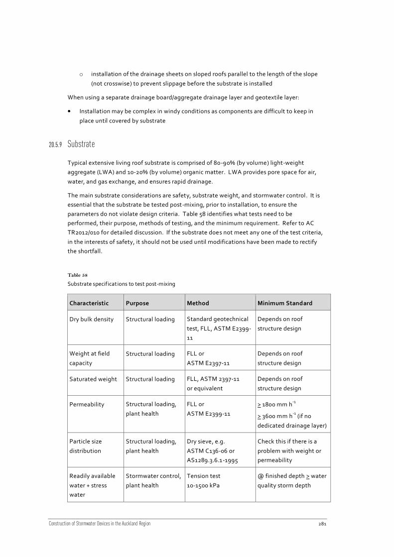
Construction of Stormwater Devices in the Auckland Region 281
o installation of the drainage sheets on sloped roofs parallel to the length of the slope
(not crosswise) to prevent slippage before the substrate is installed
When using a separate drainage board/aggregate drainage layer and geotextile layer:
Installation may be complex in windy conditions as components are difficult to keep in
place until covered by substrate
20.5.9 Substrate
Typical extensive living roof substrate is comprised of 80-90% (by volume) light-weight
aggregate (LWA) and 10-20% (by volume) organic matter. LWA provides pore space for air,
water, and gas exchange, and ensures rapid drainage.
The main substrate considerations are safety, substrate weight, and stormwater control. It is
essential that the substrate be tested post-mixing, prior to installation, to ensure the
parameters do not violate design criteria. Table 58 identifies what tests need to be
performed, their purpose, methods of testing, and the minimum requirement. Refer to AC
TR2012/010 for detailed discussion. If the substrate does not meet any one of the test criteria,
in the interests of safety, it should not be used until modifications have been made to rectify
the shortfall.
Table 58
Substrate specifications to test post-mixing
Characteristic Purpose Method Minimum Standard
Dry bulk density Structural loading Standard geotechnical
test, FLL, ASTM E2399-
11
Depends on roof
structure design
Weight at field
capacity
Structural loading FLL or
ASTM E2397-11
Depends on roof
structure design
Saturated weight Structural loading FLL, ASTM 2397-11
or equivalent
Depends on roof
structure design
Permeability Structural loading,
plant health
FLL or
ASTM E2399-11
> 1800 mm h-1
> 3600 mm h-1
(if no
dedicated drainage layer)
Particle size
distribution
Structural loading,
plant health
Dry sieve, e.g.
ASTM C136-06 or
AS1289.3.6.1-1995
Check this if there is a
problem with weight or
permeability
Readily available
water + stress
water
Stormwater control,
plant health
Tension test
10-1500 kPa
@ finished depth > water
quality storm depth

Construction of Stormwater Devices in the Auckland Region 282
Physically getting living roof materials onto a rooftop provides several challenges. Substrate
installation may be independent of planting. As substrate installation likely requires
mechanised equipment, new construction should coordinate (at least) substra te installation
with the presence of other mechanised equipment (e.g. crane or blower) on site to save cost.
Two primary options are available for installing substrate:
Crane hoist of bags
o Bagging of substrate in 1 m3 bags is typical for most media suppliers
despite being characterised as “light-weight”, a 1 m3 substrate-filled bag
may weigh in excess of 800 kg m-2
bags should not be emptied as a point load directly onto the roof, unless
the roof is designed to manage such a load
o Cranes are usually available on-site for new construction
As the building shell is often the first task for completion, a living roof can
be installed as soon as the waterproof membrane is installed and leak -
tested
Plants are allowed time to become established while the building interior
is completed; the living roof is then “ready” when the occupants take up
residency
o For retrofit installations, the crane must be able to get close enough to the building
limiting factor in specifying crane size may be reach, rather than lift
(weight) capacity in order to avoid damage to street trees or neighbouring
buildings
Blowing or spraying substrate to height
o Specialty pneumatic blowers are often used in erosion control to rapidly seed bare
surfaces, the same type of equipment can be used to transport substrate to a
rooftop
o Length of the hose may limit the height to which substrate can be blown, and is
specific to the service provider
o Contingency costs should be incorporated, as substrate may coat building facades
and thus require post-installation cleaning
o Operation of blowers may be compromised in cold weather, as the system may
clog (in which case bag hoists would be a preferred option)
Extensive living roof substrates should be hand-spread using rakes (with small tines so as not
to break the geotextile) or other methods which do not promote compaction.
Nonetheless, some compaction will occur over time due to planting and weeding activities.
The substrate materials will also settle due to self-weight and plant mass. It is recommended
to anticipate compaction of 10%; substrate depth should be increased accordingly during
installation.

Construction of Stormwater Devices in the Auckland Region 283
When installing substrate on sloped roofs, install the substrate from the base of the slope back
towards the ridge to prevent slippage.
20.5.10 Access
Ensure the project site has space in which the equipment needed to store (if needed) and
install the substrate and plants can operate, as large trucks and cranes may be needed.
Substrate can rarely be stored on the roof without overloading the structure. If the substrate
is not bagged, it will need to be protected from weeds and insect colonisation. The water
content of the substrate also needs careful management: dry substrates may create a dust
and health hazard (associated with use of composts); very wet substrates are heavy, slower,
and more difficult to spread, may be susceptible to degradation through compaction.
It is important to minimise foot traffic over the living roof, unless it is designed for such.
Excess foot traffic will result in compaction of the substrate and thus reduced permeability;
water in excess of the system storage capacity may not be able to exit the roof during large
rainfall events (a potential safety issue).
Allow for access paths between plantings to access air vents and air conditio ning units and
maintain plants. Gravel edging around living roof edges, outlets, and protrusions allow s for
easy identification of, and access to, these potential weak points in the water proofing.
Furthermore, they prevent plant material overgrowing and clogging installations such as
outlets or air conditioning units.
Worker safety must be considered as for many living roof installations the work will be
conducted at height. Appropriate harnesses, restraints and/or barriers, in addition to
appropriate training for working at height, may be required.
20.5.11 Planting
Living roofs plants are selected based on their ability to withstand the harsh conditions found
on a living roof. Plant selection for living roofs should be based on an assessment of each
individual living roof, and where the features listed below vary across a roof, sections of the
living roof for:
Minimal irrigation or fertiliser needs
Shallow root depth
Low nutrient requirements (for extensive living roofs)
Dense, self-repairing foliage cover
Low mature plant height (to reduce effects of wind exposure which may dessicate plants)
Drought and wet season tolerance
Full sun tolerance
Unlikely to spread off roof to neighbouring properties
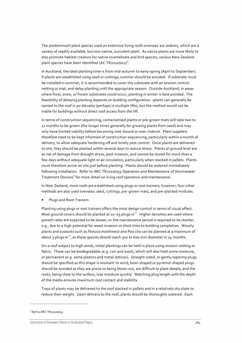
Construction of Stormwater Devices in the Auckland Region 284
The predominant plant species used on extensive living roofs overseas are sedums, which are a
variety of readily available, but non-native, succulent plant. As native plants are more likely to
also promote habitat creation for native invertebrate and bird species, various New Zealand
plant species have been identified (AC TR2010/012)4.
In Auckland, the ideal planting time is from mid-autumn to early-spring (April to September).
If plants are established using seed or cuttings, summer should be avoided. If substrate must
be installed in summer, it is recommended to cover the substrate with an erosion control
netting or mat, and delay planting until the appropriate season. Outside Auckland, in areas
where frost, snow, or frozen substrates could occur, planting in winter is best avoided. The
feasibility of delaying planting depends on building configuration –plants can generally be
carried to the roof in an elevator (perhaps in multiple lifts), but the method would not be
viable for buildings without direct roof access from the lift.
In terms of construction sequencing, containerised plants or pre-grown mats will take two to
12 months to be grown (the longer times generally for growing plants from seed) and may
only have limited viability before becoming root-bound or over-mature. Plant suppliers
therefore need to be kept informed of construction sequencing, particularly within a month of
delivery, to allow adequate hardening off and timely pest control. Once plants are delivered
to site, they should be planted within several days to reduce stress. Plants at ground level are
at risk of damage from drought stress, pest invasion, and cannot be stored for more than a
few days without adequate light or air circulation, particularly when stacked in pallets. Plants
must therefore arrive on site just before planting. Plants should be watered immediately
following installation. Refer to ARC TR2010/053 Operation and Maintenance of Stormwater
Treatment Devices5 for more detail on living roof operation and maintenance.
In New Zealand, most roofs are established using plugs or root tra iners, however, four other
methods are also used overseas: seed, cuttings, pre -grown mats, and pre-planted modules.
Plugs and Root Trainers
Planting using plugs or root trainers offers the most design control in terms of visual effect.
Most ground covers should be planted at 10–25 plugs m-2
. Higher densities are used where
growth rates are expected to be slower, or the maintenance period is required to be shorter,
e.g., due to a high potential for weed invasion or short time to building completion. Wood y
plants and tussocks such as Festuca matthewsii and Poa cita can be planted at a maximum of
about 5 plugs m-2
, as these species should reach 300 to 600 mm diameter in 24 months.
On a roof subject to high winds, initial plantings can be held in place using erosion netting or
fabric. These can be biodegradable (e.g. coir and wool), which will also hold some moisture,
or permanent (e.g. some plastics and metal lattices). Straight-sided, or gently tapering plugs
should be specified as this shape is resistant to wind; bowl-shaped or pyramid-shaped plugs
should be avoided as they are prone to being blown out, are difficult to plant deeply, and the
roots, being close to the surface, lose moisture quickly. Matching plug length with the depth
of the media ensures maximum root contact and stability.
Trays of plants may be delivered to the roof stacked in pallets and in a relatively dry state to
reduce their weight. Upon delivery to the roof, plants should be thoroughly watered. Each
5 Ref to ARC TR2010/053

Construction of Stormwater Devices in the Auckland Region 285
plug should be visually inspected before planting so any weeds can be removed to disposal
containers and out-of specification plants separated. This process should occur on a hard
surface (without substrate) or groundsheet on top of the substrate to minimise the
establishment of unwanted insects, lizards, slugs, snails, and weeds to the roof. Empty trays
should also be stored off the substrate as the underside of trays and gap between potting mix
and pot are common places for invertebrates to hide. Where biosecurity is extremely
important, e.g. for creation of NZ native invertebrate habitats, plants should be removed from
their containers on the ground.
Cuttings
Sedum living roofs are commonly established in North America by spreading cuttings during
favourable seasons at a density of about 12 to 25 kg 100 m-2
. Many sedum species will readily
sprout from stem segments or leaves that break from the parent plant, and spread this way on
established roofs. Sedum cuttings do not need to be inserted into the substrate, but they
should be held down until plants take root. An erosion mat, netting or tacifier (sticky
substance) promotes contact of the cuttings with the substrate. Under Auckland autumn
conditions, Sedum cuttings root in two to four weeks and remain viable for several months.
Broadcasting cuttings generally gives low design control in terms of visual effect, but the
installation cost is greatly reduced compared to planting if successful, i.e., if post -
establishment conditions allow the cuttings to anchor into the substrate an d grow; temporary
irrigation increases the likelihood of good establishment.
Some native NZ plants can be established from rooted cuttings and divisions planted into the
surface. Rooted cuttings have been used to successfully establish Coprosma (C. acerosa incl.
‘Hawera’) and Libertia peregrinans on a few living roofs. Hebes and Disphyma (iceplants)
should also be readily-established from rooted cuttings at favourable times of the year, while
some Arthropodiums are readily divided; however, few roofs have used these techniques to
establish native plants on living roofs to date. Bromeliads and many succulents can be similarly
propagated by removing partly-rooted ‘pups’ from adult plants. An advantage of using ‘pups’,
divisions or rooted cuttings is the greater resilience once established compared to mature
plants.
Cuttings are most successful when the time to establishment of roots is reduced - this is
influenced by temperature, moisture availability, and extent of contact of the stems/rooted
sections with substrate. Generally, wetter and warmer conditions favour establishment from
cuttings.
Seed, straw and bulbs
Living roofs can be vegetated by broadcasting seed, hydroseeding seeds, moss and plant
fragments and by hand-planting bulbs. Very few roofs are established solely with seed
because plants would take too long to establish, leaving a roof vulnerable to weeds and
erosion. Extensive living roofs with their coarse media and high evaporation rates (low
humidity, high wind and sun exposure) are relatively hostile environments for seed
germination; optimum autumn or spring sowing is a key success factor, as is provision of
irrigation.
Small, early-flowering, summer-dormant bulbs in the onion (Allium), tulip (Tulipa), and Iris
genera are used in Europe and North America to add seasonal interest and height to extensive
living roofs. The main disadvantage to use of bulbs is dead and dying foliage in summer that

Construction of Stormwater Devices in the Auckland Region 286
is both unsightly (close up) and can create bare patches that are available for weed
establishment. It is recommended that bulbs are therefore best planted singly or in small
groups combined with plants that cover the ground throughout the year. A minimum
substrate depth of 100 mm is recommended for bulb species other than chives.
A variety of biodegradable coir (coconut fibre) and wool-based blankets that can be pre-
seeded have become available in New Zealand over the last few years. These products have
been used primarily for establishing grasses in erosion-prone areas, but could be adapted for
use on living roof installations. A key factor is ensuring the blanket can be securely fixed to
the roof, to avoid being blown from the roof, as traditional pegs cannot be used without
potential damage to the waterproofing layer. Such mats can be used onl y in wind-prone areas
or to temporarily reinforce surfaces where water runs onto a roof from higher surfaces.
In Switzerland and in London, on sites where the design objective is a local ruderal (‘wasteland
or river-gravels’) or meadow flora and insect fauna, substrates may be left uncovered at
ground level to naturally ‘inoculate’ with local seeds and non-flying insects. Storing substrate
on pallets enabled it to be craned onto the roof with minimal disturbance to invertebrates.
Hay containing seed heads, spread at about 20 mm depth is also being used on some projects.
Both approaches require vigilant, informed weed maintenance to prevent establishment of
very aggressive species. An extended maintenance period is also likely unless ‘placeholder’
species such as sedums are used to reduce the area of bare ground into which weeds can
establish. In urban and rural New Zealand, this approach is unlikely to favour establishment of
native species.
Pre-grown mat, sod and containers
Pre-grown mat, sod and containers offer an instantaneous effect upon installation and are
therefore particularly useful for sites, or parts of sites, with a high erosion risk and for
temporary installations. Such mats require 4–8 months to grow before installation. Mats and
sods are often rolled up for transport and installation. In this form plant roots are exposed and
must be protected from drying out (wind and sunshine); they also need to be protected from
sunlight to minimise the risk of ‘composting’. Effective coordination be tween the mat or sod
supplier, living roof installation team and main building contractor is therefore required to
avoid storage by ensuring access for delivery trucks to the loading site and lifting equipment is
available (e.g. a crane or forklift) when plants arrive. Ideally, the mat or sod should arrive on-
site on the day of installation to avoid storing for more than a couple of days.
Sods should be grown in the living roof substrate to avoid layering and ensure consistency
with roof loading and infiltration rate specifications. However, there is also potential to
design living roofs to receive sod cut from suitable native ecosystems with shallow rooting
depths, if hydrological conditions can be matched. Such roofs would be most likely where
structures are ‘inserted’ into highly sensitive natural landscapes, using sod transfer techniques
developed in the mining industry. Both sods and mats generally have thin substrate, and
plant roots are cut prior to transportation – both increase plant stress. Irrigation is necessary
until roots grow into underlying substrate. If mats are prone to shrinkage on drying, irrigation
is needed to avoid exposing underlying roof components.
Containerised, or modular, systems are commonly planted and grown before instal lation.
Modular systems have recently become available in New Zealand; the most resilient and
aesthetic systems have substantial substrate contact between adjacent modules, enabling

Construction of Stormwater Devices in the Auckland Region 287
plant roots to travel between containers, reducing edge effects and minim ising the potential
for ‘stripes’ to develop below tray edges when plants are drought-stressed. Biodegradable
containers also reduce the edge effect. Containers are particularly suited to risk -averse clients
as they can be removed (provided plastic edges are not exposed and degraded by UV),
allowing easier maintenance of membranes – they therefore are common in North America, a
relatively new living roof market, and likely to be popular in New Zealand. Modules can also
be carried up stairs and lifts, and placed over existing membranes, thus suiting small retrofit
applications. However modular systems are uncommon in Germany and Switzerland where
living roofs are common and extensive roofs have been installed for decades.
Pre-grown mats, sods and containerised systems have a high potential for introducing both
desirable and undesirable invertebrates and plants. On the University of Auckland living roof,
the sedum mat was the source of some ‘weeds’ (narrow leaf plantain and dandelion), the
beneficial earthworm population, as well as four slug and snail species (all non-native).
20.6 Construction specifications
Table 59
Specifications for the construction of living roofs should consider the following:
Area Items to include
Insulation
layer
• Type, manufacturer, and thickness of insulation required.
Waterproof
membrane
• Type, supplier, and minimum thickness of the membrane required
Drainage
layer
• Type of drainage layer required: mat/board or aggregate
• If mat/board: supplier, product type, whether it will be installed “cups
up” for more water retention or “cups down” (where applicable), and
depth.
• If aggregate: the grade, material type, and installed depth.
Root barrier/
geotextile
• Type of non-woven geotextile material or root barrier (both may be
included with the drainage mat/board).
• Details should include the required overlap and whether the root barrier
is sealed.
Growing
media/
substrate
• Detailed description of the composition of the growing media will
typically be included with the design drawings (aggregate and organic
component source, particle size distribution, mixing method)
• Specifications should detail the quality of the media required, including
tests to ensure the minimum requirements are met prior to installation
• Final depth, including allowance for compaction/settling).

Construction of Stormwater Devices in the Auckland Region 288
Area Items to include
Plants • A planting schedule is normally included with the drawings and will
provide details on the type (genus and species), and size (e.g. plugs,
cuttings etc.) of the plants required as well as spacing and planting
method.
• Specifications should enforce compliance with this planting schedule.
Outlet • The diameter, size, type and material of the outlet.
Edging • Material type, and aggregate grade
• Width of perimeter edging, fire breaks, and edging around outlets
and/or protrusions
Example specifications are shown in Section 20.9. These cover some of the typical aspects for
construction of living roofs, but exclude particulars such as site establishment, health and
safety, testing, materials, and reinstatement, as these differ greatly depending on the
application.
These example specifications do not constitute a full specification for the construction of any
living roof, and should be used as a ‘starter specification’ for guidance only. Each living roof
will be site specific and require careful consideration to ensure that all aspects of construction
are covered.
20.7 Construction monitoring
Table 60
Crit ical points to inspect during construction to ensure the device is installed correctly include:
Area Items to monitor
Insulation
layer
• Insulation layer installed by a qualified contractor as per the
manufacturer’s specifications.
Waterproof
membrane
• Waterproof membrane installed by qualified contractor as per
manufacturer’s specifications.
• Impermeability test shows no leaks (if flood testing, over a minimum
period of 24 hours but preferably 48 hours).
• Post installation, ensure none of the waterproofing is exposed, to
prevent weathering or damage.
• If using EFVM, perform impermeability tests on the waterproof
membrane post installation to ensure no damage occurred during
installation of subsequent layers.
• Photograph the membrane and application process for inclusion in
the operation and maintenance manual. This will help when
troubleshooting problems in the future.
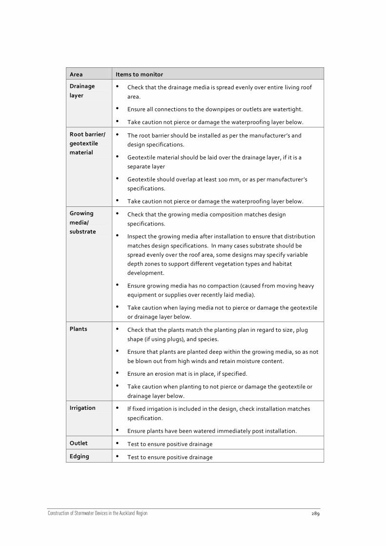
Construction of Stormwater Devices in the Auckland Region 289
Area Items to monitor
Drainage
layer
• Check that the drainage media is spread evenly over entire living roof
area.
• Ensure all connections to the downpipes or outlets are watertight.
• Take caution not pierce or damage the waterproofing layer below.
Root barrier/
geotextile
material
• The root barrier should be installed as per the manufacturer’s and
design specifications.
• Geotextile material should be laid over the drainage layer, if it is a
separate layer
• Geotextile should overlap at least 100 mm, or as per manufacturer’s
specifications.
• Take caution not pierce or damage the waterproofing layer below.
Growing
media/
substrate
• Check that the growing media composition matches design
specifications.
• Inspect the growing media after installation to ensure that distribution
matches design specifications. In many cases substrate should be
spread evenly over the roof area, some designs may specify variable
depth zones to support different vegetation types and habitat
development.
• Ensure growing media has no compaction (caused from moving heavy
equipment or supplies over recently laid media).
• Take caution when laying media not to pierce or damage the geotextile
or drainage layer below.
Plants • Check that the plants match the planting plan in regard to size, plug
shape (if using plugs), and species.
• Ensure that plants are planted deep within the growing media, so as not
be blown out from high winds and retain moisture content.
• Ensure an erosion mat is in place, if specified.
• Take caution when planting to not pierce or damage the geotextile or
drainage layer below.
Irrigation • If fixed irrigation is included in the design, check installation matches
specification.
• Ensure plants have been watered immediately post installation.
Outlet • Test to ensure positive drainage
Edging • Test to ensure positive drainage

Construction of Stormwater Devices in the Auckland Region 290
20.8 Photo gallery – living roofs
Figure 130
Victoria Ave living roof.
Figure 131
Furneaux Lodge house living roof.
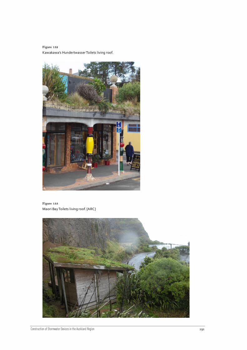
Construction of Stormwater Devices in the Auckland Region 291
Figure 132
Kawakawa’s Hundertwasser Toilets living roof.
Figure 133
Maori Bay Toilets living roof. [ARC]
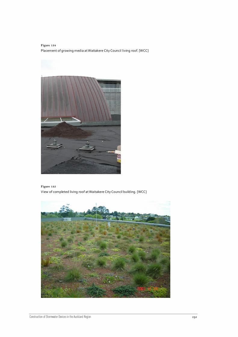
Construction of Stormwater Devices in the Auckland Region 292
Figure 134
Placement of growing media at Waitakere City Council living roof. [WCC]
Figure 135
View of completed living roof at Waitakere City Council building. [WCC]
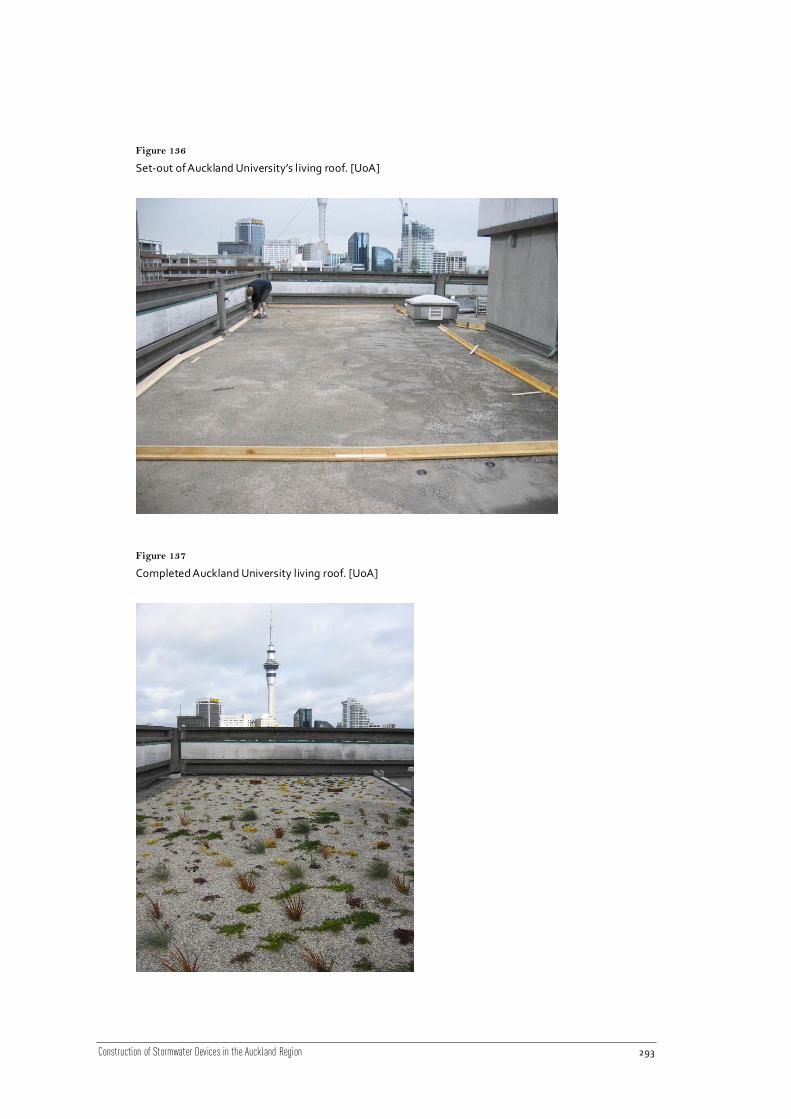
Construction of Stormwater Devices in the Auckland Region 293
Figure 136
Set-out of Auckland University’s living roof. [UoA]
Figure 137
Completed Auckland University living roof. [UoA]
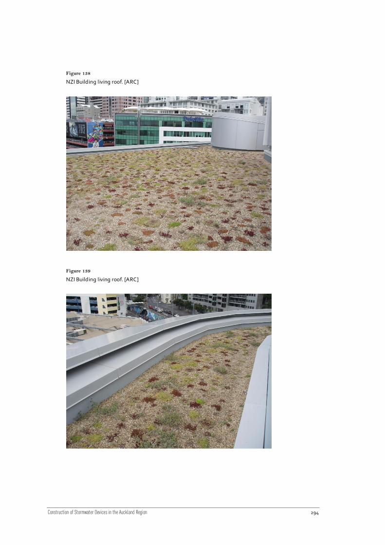
Construction of Stormwater Devices in the Auckland Region 294
Figure 138
NZI Building living roof. [ARC]
Figure 139
NZI Building living roof. [ARC]

Construction of Stormwater Devices in the Auckland Region 295
Figure 140
Botanic Gardens Toilet Block living roof: waterproofing membrane and stainless steel edging
Figure 141
Botanic Gardens Entrance living roof: drainage mat installat ion, note overlap of the geotextile (f ilter
cloth)

Construction of Stormwater Devices in the Auckland Region 296
Figure 142
Botanic Gardens Entrance living roof: temporary wooden edging for placement of gravel edging stones,
drainage mat extends under the zone in which edging stones were placed, bags of stones keeping joins in
drainage mat in place.
Figure 143
Substrate installat ion: Left - Botanic Gardens Entrance living roof, installing substrate from edging
inwards and upslope; right- an alternative method of spreading substrate straight from the truck (private
garage with the same substrate).
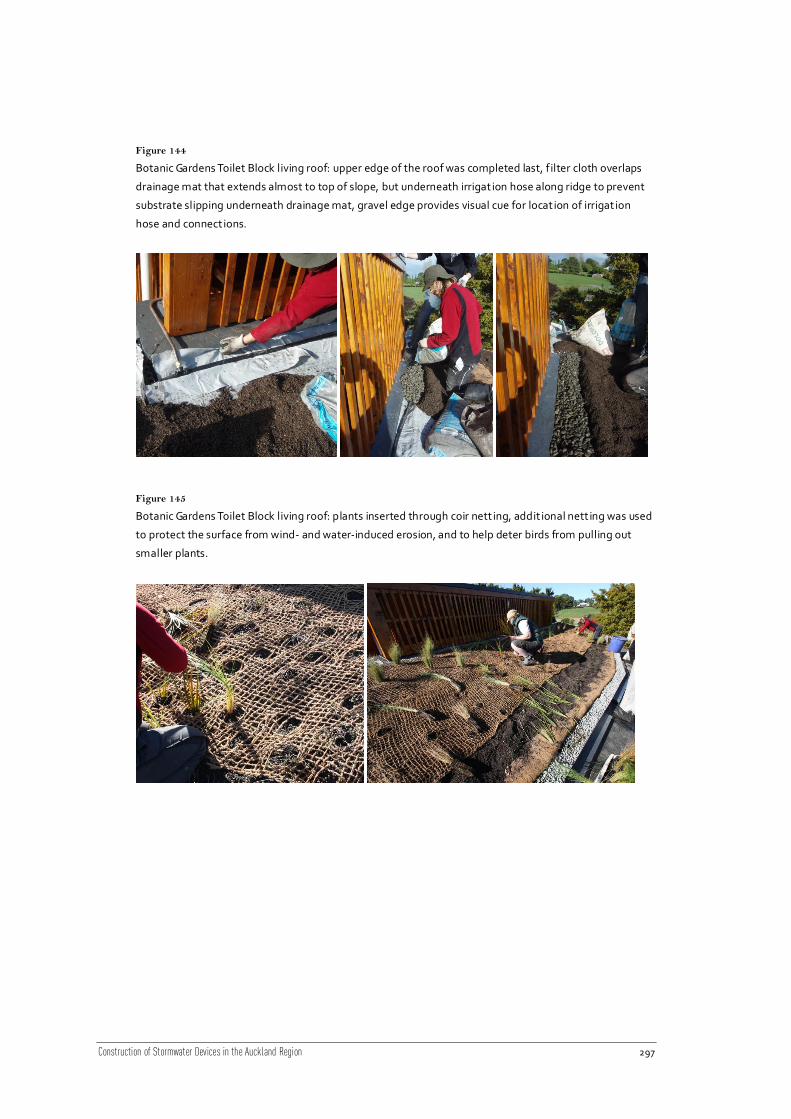
Construction of Stormwater Devices in the Auckland Region 297
Figure 144
Botanic Gardens Toilet Block living roof: upper edge of the roof was completed last, f ilter cloth overlaps
drainage mat that extends almost to top of slope, but underneath irrigation hose along ridge to prevent
substrate slipping underneath drainage mat, gravel edge provides visual cue for location of irrigation
hose and connections.
Figure 145
Botanic Gardens Toilet Block living roof: plants inserted through coir nett ing, addit ional nett ing was used
to protect the surface from wind- and water-induced erosion, and to help deter birds from pulling out
smaller plants.

Construction of Stormwater Devices in the Auckland Region 298
Figure 146
Botanic Gardens Toilet Block living roof: watering the roof immediately after planting helps plant
establishment, cleans stones, and tests drainage and gutters
20.9 Construction specification example – living roofs
20.9.1 Living roof components
20.9.1.1 Insulation layer
[This is optional] Installed to the manufacturer’s instructions.
20.9.1.2 Waterproof membrane
The membrane shall be installed as per the manufacturer’s instructions. The membrane shall
be waterproof and after installation an electric field vector mapping (EFVM) impermeability
test shall be undertaken. Any identified weaknesses, punctures, or leaks must be repaired
before any other layers are installed.
20.9.1.3 Drainage layer
If using a specialty product with integrated geotextile (filter fabric), and root barrier, the
drainage layer shall be installed as per the manufacturer’s instructions. The dra inage layer
should be installed such that the geotextile is placed with overlaps of at least 100 mm.
Installation of drainage sheets on sloped roofs should be parallel to the length of the slope
(not crosswise) to prevent slippage before the substrate is installed.
If using aggregate, the drainage layer shall be laid on the living roof as detailed on the
drawings.

Construction of Stormwater Devices in the Auckland Region 299
20.9.1.4 Root barrier
The root barrier can be combined with the geotextile layer as a laminated upper layer; as a
separate layer above the waterproof membrane, or by chemical additives in the waterproof
membrane.
20.9.1.5 Geotextile layer
The filter layer can be a single layer of non-woven geotextile, installed separate to the
drainage layer (aggregate or mat), or can be affixed to a proprietary living roof drainage mat.
20.9.1.6 Growing media
Growing media composition shall comply with the design specification.
Construction specifications should identify the tests required to confirm adherence to the
minimum design specifications prior to installation, and the method of installation.
The installed depth of substrate should be increased to anticipate 10% compaction to achieve
the final design depth.
20.9.1.7 Planting schedule
Planting shall comply with the planting schedule. Plant spacing shall comply with the plan
and shall be at the spacing intervals defined for each species with holes dug for plants deep
enough so as to cover the root ball of the specimen.
Caution must be taken during planting not to damage the geotextile and drainage layer
below.
20.9.1.8 Outlet
The outlet shall be connected to the spouting by a PVC pipe as detailed on the drawings. PVC
pipes shall be manufactured in accordance with AS/NZS 1260 “PVC Pipes and Fittings” and
installed in accordance with NZS 7643 “Installing uPVC Pipes”. The outflow connection to the
stormwater system shall comply with NZS4404:2004 and as per the local council standards.
20.9.1.9 Irrigation and water supply
If a permanent irrigation system is specified, connection to the mains for irrigation shall be as
detailed on the drawings and shall comply with the local council standards for connection to
water mains and the NZ Building Code.

Construction of Stormwater Devices in the Auckland Region 300
21 Infiltration Trenches and Wells
21.1 Introduction
There are vast array of infiltration devices in use in the Auckland region, often designed for
specific site and geological conditions. Infiltration devices are often known as soakholes. Rain
gardens, swales and permeable paving systems can also be constructed for infiltration of
stormwater, rather than discharge to stormwater reticulation systems. This chapter only
looks at infiltration trenches and dry wells, which are also known as private soakage.
Soakholes and larger public infiltration systems are often made of precast concrete chambers
with perforations allowing water to percolate to the next chamber and ultimately the
surrounding ground. Some also include bores that extend into underlying aquifers to
maximise soakage and disposal rates.
21.2 Device description
All infiltration devices direct stormwater runoff to the underlying geology and ultimately
groundwater. The key function of infiltration devices is to reduce the volume of stormwater
runoff, reduce surface water contaminant loadings, and extend baseflow in streams. Runoff is
stored in an open chamber or the void space between the storage medium (aggregate) and
slowly permeates into the surrounding ground where natural biological processes can improve
water quality. Infiltration devices are most effective in permeable natural soils with water
tables a minimum of 1 m below the base of the device.
Infiltration devices can have high failure rates if careful consideration is not given to site
selection and maintenance. Catchment characteristics, particularly potential sources of
pollution (e.g. oil, grease, high sediment loads) need to be identified and suitable pre -
treatment included in the design of the infiltration device. There is also significant risk of
polluting groundwater if runoff is not sufficiently treated prior to infiltration. Geotechnical
stability also requires consideration to avoid ground failure caused by too much water
permeating the ground.
Infiltration trenches: Trenches can be buried and receive inflow either from pipes or surface
trenches that receive sheet flow runoff. Pre-treatment is essential to prevent the trench from
clogging. Infiltration rates should be between 3 mm hr-1
and 1 m hr-1
in order to achieve
attenuation and treatment, and their suitability is therefore highly dependent on geology.
Trenches with a piped inflow point often have a dispersion pipe the length of the trench to
evenly disperse runoff. In this situation a trench may be grassed, however clear delineations
are required to protect the trench from any activities which could compact the soil and trench
(e.g. vehicle or pedestrian traffic).
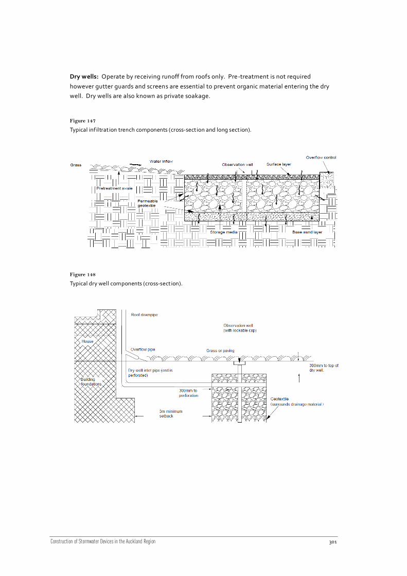
Construction of Stormwater Devices in the Auckland Region 301
Dry wells: Operate by receiving runoff from roofs only. Pre-treatment is not required
however gutter guards and screens are essential to prevent organic material entering the dry
well. Dry wells are also known as private soakage.
Figure 147
Typical infiltrat ion trench components (cross-sect ion and long sect ion).
Figure 148
Typical dry well components (cross-sect ion).
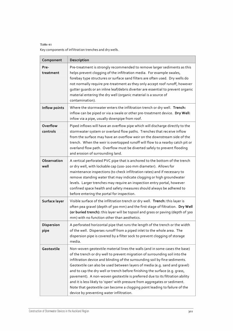
Construction of Stormwater Devices in the Auckland Region 302
Table 61
Key components of infiltrat ion trenches and dry wells.
Component Description
Pre-
treatment
Pre-treatment is strongly recommended to remove larger sediments as this
helps prevent clogging of the infiltration media. For example swales,
forebay type structures or surface sand filters are often used. Dry wells do
not normally require pre-treatment as they only accept roof runoff, however
gutter guards or an inline leaf/debris diverter are essential to prevent organic
material entering the dry well (organic material is a source of
contamination).
Inflow points Where the stormwater enters the infiltration trench or dry well. Trench:
inflow can be piped or via a swale or other pre-treatment device. Dry Well:
infow via a pipe, usually downpipe from roof.
Overflow
controls
Piped inflows will have an overflow pipe which will discharge directly to the
stormwater system or overland flow paths. Trenches that rec eive inflow
from the surface may have an overflow weir on the downstream side of the
trench. When the weir is overtopped runoff will flow to a nearby catch pit or
overland flow path. Overflow must be diverted safely to prevent flooding
and erosion of surrounding land.
Observation
well
A vertical perforated PVC pipe that is anchored to the bottom of the trench
or dry well, with lockable cap (100-200 mm diameter). Allows for
maintenance inspections (to check infiltration rates) and if necessary to
remove standing water that may indicate clogging or high groundwater
levels. Larger trenches may require an inspection entry portal, however
confined space health and safety measures should always be adhered to
before entering the portal for inspection.
Surface layer Visible surface of the infiltration trench or dry well. Trench: this layer is
often pea gravel (depth of 300 mm) and the first stage of filtration. Dry Well
(or buried trench): this layer will be topsoil and grass or paving (depth of 300
mm) with no function other than aesthetics.
Dispersion
pipe
A perforated horizontal pipe that runs the length of the trench or the width
of the well. Disperses runoff from a piped inlet to the whole area. The
dispersion pipe is covered by a filter sock to prevent clogging of storage
media.
Geotextile Non-woven geotextile material lines the walls (and in some cases the base)
of the trench or dry well to prevent migration of surrounding soil into the
infiltration device and blinding of the surrounding soil by fine sediments.
Geotextile can also be used between layers of media (e.g. sand and gravel)
and to cap the dry well or trench before finishing the surface (e.g. grass,
pavement). A non-woven geotextile is preferred due to its filtration ability
and it is less likely to ‘open’ with pressure from aggregates or sediment.
Note that geotextile can become a clogging point leading to failure of the
device by preventing water infiltration.

Construction of Stormwater Devices in the Auckland Region 303
Component Description
Storage
media
The component of the trench or dry well that provides storage of runoff
(depth typically 1-2 m). Usually aggregate, runoff is stored in the voids
which are usually 30%-40% of the total volume. Aggregate size will vary
with the necessary infiltration rate but are often graded between 25 to
75 mm.
Base sand
filter
At the bottom layer of the trench (not usually present in dry wells) and
provides enhanced treatment of runoff. Depth of 150 mm to 300 mm. Can
add fibric or hemic peat to target particular contaminants, however the
addition of peat will reduce infiltration rates so must be considered during
design phase. Geotextile can be used between the sand and the storage
media.
21.3 Guideline documents
Guidelines relating particularly to infiltration devices are listed in the following table. Note
that a detailed review of council standards and guidelines should be carried out for every
project, as these are frequently updated.
Table 62
Guideline documents relat ing part icularly to infiltrat ion devices.
Publisher Title Description
ACC On-site Stormwater
Management
Guidelines for the reduction of impacts of
stormwater runoff (water quantity) and
pollution (water quality) resulting from
intensive development throughout the city.
Information on specific stormwater
management devices.
ACC Soakage Design Manual This manual solely addressing infiltration
devices, including percolation testing, types of
devices, design procedures, construction, and
operation and maintenance.
ARC TP90 Erosion and Sediment
Control Guidelines for Land
Disturbing Activities in the
Auckland Region
These guidelines outline the principals of
erosion and sediment control and control
measures that should be used.
ARC TP124 Low Impact Design
Manual for the Auckland
Region
Approaches to site design and development
from a stormwater management context,
primarily applicable for residential land
development.

Construction of Stormwater Devices in the Auckland Region 304
Publisher Title Description
ARC TP95 Long-term Baseline
Groundwater Chemistry
Provides a database of groundwater quality of
the primary aquifers in the region. This is
useful when determining pre-treatment water
quality objectives if discharge is to an aquifer.
ARC Regional aquifer allocation,
management plans and
resource assessment reports
Plans and reports for specific regions with
groundwater resources. Provides information
on allocation, availability, specific quality or
quantity issues and threats.
LTSA Integrated Stormwater
Management Guidelines for
the New Zealand Roading
Network
Provides guidance on a range of issues relating
to the management of stormwater run-off
from state highways and local roads in New
Zealand.
NZWWA On Site Stormwater
Management Guideline
Provides guidance on the design of on-site
stormwater management devices for the
majority of applications in New Zealand.
WCC Stormwater Solutions for
Residential Sites
Document providing guidance on
management practices applicable to
developments on individual residential lots
(<1000 m²). For use by engineers and
applicants for stormwater control building
permits for developments of this size.
21.4 Standards and technical documents
Table 63
Below is a non-exhaustive list of some of the more applicable standards and technical documents that
relate to infiltrat ion trenches and dry wells:
Title Description
AS/NZS 2033:2008
Installation of
Polyethylene Pipe
Systems
Specifies methods for handling, storage, installation, testing and
commissioning of polyethylene (PE) pipelines, above or below
ground, for pressure and non-pressure applications conveying
liquids.
AS/NZS 2566.2:2002
Buried Flexible Pipelines –
Installation
Specifies requirements for the installation, field testing and
commissioning of buried flexible pipelines with structural design
in accordance with AS/NZS 2566.1.

Construction of Stormwater Devices in the Auckland Region 305
Title Description
NZS 7643:1979 Code of
Practice for the
Installation of
Unplasticized PVC Pipe
Systems
Details requirements for the installation of uPVC pipes.
SNZ HB 2002:2003
Code of Practice for
Working in the Road
This Handbook deals with aspects of the roles and
responsibilities of Road Controlling Authorities, principal
providers, utility operators and contractors; consents and work
approvals; and details of construction requirements; for the
purpose of installation and maintenance of utilities within the
road corridor.
AS/NZS 1547:2000 Onsite
Domestic Wastewater
Management (Appendix
4.1F Soil Permeability
Measurement – Constant-
Head Test)
Appendix 4.1F outlines the methods and formula for testing
permeability of in-situ soils.
AS/NZS 4411:2001
Environment Standard for
Drilling of Soil and Rock
This Standard sets out the minimum national environmental
performance requirements for drilling of soil and rock, the
design, construction, testing and maintenance of bores, the
decommissioning of holes and bores, and record keeping.
Required for any rock bore infiltration devices.
21.5 Construction considerations
21.5.1 Infiltration trench and dry well location
The catchment for an infiltration trench should be about two hectares (maximum four
hectares) while a dry well catchment can be significantly smaller. Infiltration devices are
usually only used in areas where the natural soil is free draining and the water table is dee p or
well below the base of the infiltration device. Test pits or bores on site can be used to
estimate infiltration rates of the surrounding geology of the site. Given the risk of
contamination of groundwater from infiltration of stormwater runoff it is essential that
comprehensive investigations are made into the suitability of a location for an infiltration
device particularly where water supply bores are found.
Trenches should follow the same contour of the site to ensure they are level. Dry wells sh ould
be located at least 3 m from any building foundations to prevent subsidence. Allow for
downpipe extension to enter dry well.

Construction of Stormwater Devices in the Auckland Region 306
21.5.2 Construction sequencing
The trench or dry well may be excavated during the earthworks stage of construction (if part
of a larger site development). If this is the case, the excavation needs to be protected from
sediment laden runoff from other construction activities and clean runoff diverted until the
catchment area has been stabilised. Impermeable geotextile can be used to ‘seal’ the
excavation. The area surrounding the trench or dry well will also need to be protected from
vehicles as any compaction will greatly reduce the infiltration rates of the natural ground.
Sediment ponds or decanting earth bunds should not be used for infiltration devices unless
the area is thoroughly dug out including any blinded natural soils.
21.5.3 Construction timing
If the dry well or trench is buried and the surface is to be grassed consideration should be
given to when grass strike will be at its greatest i.e. autumn or spring. If the infiltration device
is to be constructed during the summer months, in line with the earthworks season, then
watering at regular intervals should be specified.
21.5.4 Permeability
Permeability of the natural soil must be maintained in order for the device to continue
functioning. At no stage during construction should the natural soil be compacted either from
tracking machinery across the area or using the area for stockpiling. When selecting the site
for the infiltration device consideration should be given to long-term protection from
activities which could compact the natural soil.
21.5.5 Site slope
Infiltration trenches should not be placed on slopes greater than 15% as the water movement
in the natural soil can cause stability problems. A comprehensive geotechnical investigation
would be required to allow an infiltration trench on a slope greater than 15%. The surface and
base of the infiltration trench or dry well must be level. If water naturally flows in a particular
direction check dams can be constructed on the bottom of the trench to prevent water
ponding in one corner.
Trenches operate best when the up gradient is 5% or less and the down gradient is up to 15%.
If the infiltration trench is a surface trench the level can be slightly lower than ground level to
capture runoff or an overflow berm can be constructed on the down gradient side of the
trench.
21.5.6 Geology
Hard rock or impermeable layers may impact on the infiltration rates of the surrounding soil
and the effectiveness of the infiltration device. During the design phase test pits or boreholes
should be constructed at least 1.5 m below the bottom of the infiltration device. This will

Construction of Stormwater Devices in the Auckland Region 307
determine infiltration rates for design. The seasonal high water table should be a minimum of
1 m from the base of the infiltration trench or well.
In areas where the slope is greater than 15% a comprehensive geotechnical investigation will
be required to determine suitability of site.
21.5.7 Pre-treatment
All infiltration devices must have some form of pre-treatment to reduce sediment loads to
help keep the device free from clogging. The extent of pre-treatment will depend on whether
the runoff is injected into an aquifer. If runoff is injected, the runoff must go through water
quality pre-treatment to achieve water quality that is geochemically compatible with the
receiving groundwater. Dry wells only receive runoff from roofs so while pre -treatment is not
strictly required, gutter guards and downpipe screens should be fitted to prevent organic
matter (e.g. leaf litter) entering the dry well.
21.5.8 Equipment
The correct equipment is very important when excavating the trench or well as the natural soil
surfaces can be sealed with certain types of machinery. Backhoe excavator or ladder type
trenchers are most suitable for excavating the trench or well (rather than front loader or
bulldozer). When excavating, care needs to be taken not to compact surrounding natural soil
with the heavy machinery. In areas with fractured rock, rock breakers may be required.
21.5.9 Structural integrity
When constructing an infiltration trench care must be taken when it is located beside hard
surfaces which potentially have heavy loads, like car parks or road ways. Retaining walls or
other reinforcing such as edge beams may be required to ensure the walls of the infiltration
trench do not collapse under the load, or the surface of the road or car park does not subside.
An alternative is to set the infiltration trench back far enough from the car parking area or
road way so as not to undermine the walls of the trench with the extra weight or the surface of
the car park or road way.
21.5.10 Surfacing
Trenches can either be buried or exposed at the surface. Buried infiltration devices (whether
trench or well) are usually topped with 300 mm of topsoil and grass with a layer of geotextile
between aggregate and topsoil for improved treatment. Consider using instant turf rather
than grass seed or hydroseeding for immediate effect and treatment.
If the trench is exposed at the surface and receives sheet inflow, consider finishing the trench
with 300 mm of pea gravel with geotextile between the storage aggregate and the pea gravel.
The pea gravel maximises filtering ability and allows for easier maintenance. If an infiltration
trench or well is not performing, check the state of the geotextile fabric as it can be a point of

Construction of Stormwater Devices in the Auckland Region 308
clogging. Refurbishing the geotextile or underlying pea gravel layer will often remedy any
infiltration problems.
21.6 Construction specifications
Table 64
Infiltrat ion trenches and wells construction specifications will need to detail:
Area Items to include
Excavation • Specify the need to verify ground conditions and soil characteristic
encountered when excavating (e.g. rock or clay layer).
• Only backhoe excavator or trencher to be used to protect natural soil
from sealing and compaction. Lateral planks can also be used to
prevent compaction of surrounding soils.
• Using teeth of the excavator to scarify the base of the infiltration
device can improve performance. Be careful not to “smear” the base
during excavation.
• Ensure levels and dimensions of the excavation including any slope
are clearly marked on construction drawings as this is critical to the
operation of the infiltration device.
• Specify health and safety procedures (e.g. Department of Labour
Code of Practice for Excavation and Shafts for Foundations).
Geotextile • Specify non-woven geotextile to be used, include length for overlap
of seams etc. If possible the name of appropriate geotextiles and the
supplier should be specified.
• Allow enough geotextile to wrap over the top of the trench or dry well
with overlap of material from either side.
Inflow and
overflow
• Inflow structure or method must be shown on construction drawings
and details of inflow pipe diameter, type and connections must be
specified.
• Show clearly on construction drawings location of overflow structures
and details of such, including diameter of any pipes, connections to
stormwater systems or erosion protection measures on overland flow
paths.
Observation
well
• The observation pipe diameter and type of perforated pipe needs to
be specified including details of connections.
• Specify footplate material and how to anchor pipe to footplate and
footplate to base of trench or well.
• Detail the observation well cap requirements particularly any locking
mechanism.
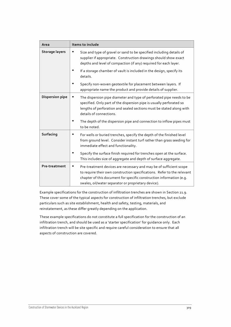
Construction of Stormwater Devices in the Auckland Region 309
Area Items to include
Storage layers • Size and type of gravel or sand to be specified including details of
supplier if appropriate. Construction drawings should show exact
depths and level of compaction (if any) required for each layer.
• If a storage chamber of vault is included in the design, specify its
details.
• Specify non-woven geotextile for placement between layers. If
appropriate name the product and provide details of supplier.
Dispersion pipe • The dispersion pipe diameter and type of perforated pipe needs to be
specified. Only part of the dispersion pipe is usually perforated so
lengths of perforation and sealed sections must be stated along with
details of connections.
• The depth of the dispersion pipe and connection to inflow pipes must
to be noted.
Surfacing • For wells or buried trenches, specify the depth of the finished level
from ground level. Consider instant turf rather than grass seeding for
immediate effect and functionality.
• Specify the surface finish required for trenches open at the surface.
This includes size of aggregate and depth of surface aggregate.
Pre-treatment • Pre-treatment devices are necessary and may be of sufficient scope
to require their own construction specifications. Refer to the relevant
chapter of this document for specific construction information (e.g.
swales, oil/water separator or proprietary device).
Example specifications for the construction of infiltration trenches are shown in Section 21.9.
These cover some of the typical aspects for construction of infiltration trenches, but exclude
particulars such as site establishment, health and safety, testing, materials, and
reinstatement, as these differ greatly depending on the application.
These example specifications do not constitute a full specification for the construction of an
infiltration trench, and should be used as a ‘starter specification’ for guidance only. Each
infiltration trench will be site specific and require careful consideration to ensure that all
aspects of construction are covered.

Construction of Stormwater Devices in the Auckland Region 310
21.7 Compliance monitoring
Table 65
Crit ical points to inspect during the construction of infiltrat ion trenches and wells to ensure the device is
installed correctly include:
Area Items to monitor
Excavation • Before breaking ground ensure erosion and sediment control measures
are set up (e.g. catch pit protectors, diversion bunds).
• Excavation to be carried out by a back hoe or ladder trencher. Check
trench bottom is level and uniform (as per drawings). Ensure bottom
and walls have not been sealed by excavation.
• Check all protrusions (e.g. tree roots and rocks) from walls and bottom
of trench have been removed.
• Natural soils must not be compacted, ensure construction machinery is
kept as far as practicable from excavation and prevent traffic movement
within 3 m of the excavation.
Geotextile • The geotextile material matches construction specifications and has
been laid, with necessary overlap as specified. Ensure there are no rips
or stress points in material.
Inflow and
overflow
• Check inverts and levels match drawings.
• Connections from inflow pipes must be watertight.
• Piped overflow connections must be watertight; overland overflow must
have erosion protection.
• If inflow is via a grass filter strip, verify the filter strip edge is le vel to
allow even, diffuse flow into the trench.
Observation
well
• Perforated observation well matches specifications and is securely
fastened to foot plate.
Storage
material
• Aggregate is washed and clean before laying in loads of 200 mm at a
time.
Dispersion
pipe/level
spreader
• Connection to inflow pipe is water tight and perforated dispersion pipe
or level spreader matches specifications.
Surfacing • Geotextile is secured over top of trench or well.
• If pea gravel is specified ensure it is washed and clean before laying.
Once laid depth should be 300 mm or as per drawings.
• If surface is grass, check topsoil depth is 300 mm (or as specified) and
turf is well watered and densely sown. Ensure a schedule of watering is
established.

Construction of Stormwater Devices in the Auckland Region 311
Area Items to monitor
Pre-
treatment
• Pre-treatment constructed as per construction drawings. See respective
device chapter depending on pre-treatment device specified e.g. swale,
oil/water separator or proprietary devices.
21.8 Photo gallery – infiltration trenches and dry wells
Figure 149
Buried infiltrat ion devices showing inspection/access ports (ACC, 2003, Soakage Design Manual).
Figure 150
Surface infiltrat ion trench along roadway (ARC, 2007, Infiltrat ion Trenches).
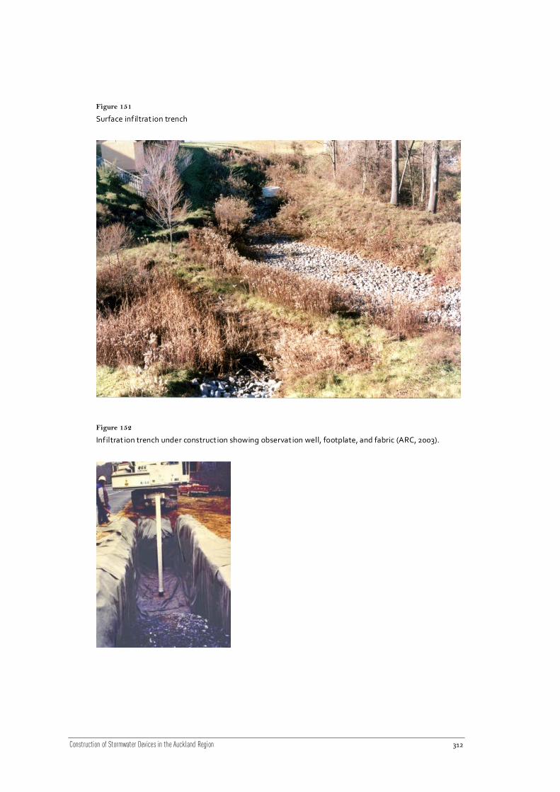
Construction of Stormwater Devices in the Auckland Region 312
Figure 151
Surface infiltrat ion trench
Figure 152
Infiltrat ion trench under construction showing observation well, footplate, and fabric (ARC, 2003).

Construction of Stormwater Devices in the Auckland Region 313
Figure 153
Infiltrat ion soakhole (private soakage).
Figure 154
Infiltrat ion soakholes, surface and interior view examples.

Construction of Stormwater Devices in the Auckland Region 314
21.9 Construction specification example – infiltration trenches
21.9.1 Site preparation
21.9.1.1 Topsoil
The Contractor shall strip the topsoil from all areas to be excavated, filled or otherwise
disturbed due to the construction of the contract works, and stockpile it in an approved
location. The depth of topsoil stripped shall be:
at least 300 mm in farmland, residential property or other cultivated areas; or
at least 150 mm elsewhere; or
the full depth of topsoil where less than the above depths exist.
21.9.1.2 Disposal of material and rubbish
All materials arising from site clearance which are surplus to or unsuitable for use in the Works
shall become the property of the Contractor and shall be disposed off the site.
All fences, buildings, structures and encumbrances of any character, except those that are
earmarked for removal by others, upon or within the limits of the site, shall be removed by the
Contractor and disposed of as directed by the Engineer.
21.9.1.3 Site fencing
The work area (excavations, stock-pile areas, etc) shall be adequately fenced to delineate their
extent and to fulfil the Contractor’s obligations of site safety and security, all to th e
satisfaction of the Engineer.
21.9.1.4 Drainage
The Contractor shall keep excavations free of water during construction and shall dispose of
the water in an approved manner.
The Contractor shall supply, install, operate and maintain all pumping, plant, pipework,
subdrains and sumps and other equipment necessary for this purpose and shall maintain at
the site at all times, reasonable standby plant in good working condition.
21.9.1.5 Disposal of water
Water from either infiltration trench installation, surface drainage of the site, or dewatering of
excavations shall be treated (e.g. passed through a silt fence, settling pond or other
treatment) in accordance with council requirements prior to discharge, and shall contain no
more than 100 mg L-1
of solids. Once treated to the required level, the water may be disposed
of downstream into the existing water course, the public road stormwater drain or public foul

Construction of Stormwater Devices in the Auckland Region 315
sewer subject to council. Where this cannot be achieved, water from excavations must be
removed off-site and disposed of in an approved manner.
Water from any lubrication system used for pipe installation may not be discharged from the
site without the approval of the Engineer.
21.9.1.6 Verification of levels
The Contractor shall take sufficient levels or cross-sections of the existing ground surfaces,
including the road surface to confirm the ground profile and levels shown on the drawings and
to ensure that the surfaces are reinstated to the levels existing at the start of the contract
works or shown on the drawings.
The Contractor shall also confirm the invert and lid levels of all wastewater and stormwater
lines and verify the depth of telecommunications, power, gas or other services which
transverse the infiltration trench location or are in the vicinity of the works. Any disagreement
or potential conflicts shall be reported to the Engineer before excavation is commenced.
21.9.1.7 Protection of existing assets and services
The Contractor shall:
Ensure that no damage beyond fair wear and tear is caused to public roads and paths.
Comply with the requirements of the Land Transport Authority transport services road
opening notice regarding protection and cleanliness of all roads and paths adjacent to the
site. Meet all costs arising from non-compliance.
Keep approaches to the site clear of mud and debris.
Comply with Local Authority requirements regarding protection of paths, kerbs and
channels.
Comply with Local Authority requirements regarding restrictions on truck movements
during peak traffic periods.
21.9.1.8 Street furniture
The Contractor shall protect all existing road signage and similar street furniture. The
Contractor shall seek approval from the LTA and the bus company if any bus-stops made
unavailable by the work. Where agreed, the bus-stops shall be replaced by temporary stops as
close as possible to the permanent site. All such furniture disturbed, damaged or removed,
including road markings, shall be fully reinstated.

Construction of Stormwater Devices in the Auckland Region 316
21.9.2 Stormwater system
21.9.2.1 Overflow pipe connection to stormwater system (if required)
Measures to divert the stormwater during construction if required, shall be installed (as
specified in the site Erosion and Sediment Control Plan) and will only be removed upon the
direction of the Engineer.
21.9.3 Excavation
21.9.3.1 Verification of ground conditions
The Contractor shall include in his price for excavation, excavation into all materials
encountered, that could reasonably be anticipated from the geotechnical information
provided, and from any further investigation undertaken by the Contractor prior to Tendering.
This shall include rock and/or tree logs or stumps if geotechnical information suggests that the
presence of rock and/or tree logs or stumps is possible. This shall also include variable material
in any filled and alluvium ground identified in the geotechnical information.
"Rock" shall be material of sufficient strength and extent that in the opinion of the Engineer it
cannot be removed efficiently using a 20 tonne size digger fitted with an appropriate narrow
"rock" bucket, and requires more intensive means for efficient excavation.
21.9.3.2 Over excavation
If the Contractor takes out any material to a greater depth or width than shown on the
drawings or specified, without the instruction of the Engineer the extra dept h or width shall be
filled with excavated material, (being native soil) as nominated by the Engineer, care must be
taken not to compact.
21.9.3.3 Excavation in road reserve
Excavation in road reserve shall be carried out in accordance with the specifications and
requirements quoted in the “Code of Practice for Working in the Road” and the LTA
requirements including any additional requirements as defined in the Road Opening Notice
and LTA Infrastructure Design Standards.
21.9.3.4 Stockpiling and removal of excavated material
All excavated material required for fill shall be properly stockpiled with steep faces to allow
maximum drainage in an approved location inside the working area. Stockpiled material shall
be covered with geotextile or polythene if rain is forecast.
Stockpiled material which deteriorates and becomes unsuitable because of avoidable delays,
poor storage arrangements or other circumstances within the Contractor's control shall be
replaced with suitable material at the Contractor's own cost.

Construction of Stormwater Devices in the Auckland Region 317
Where material is stockpiled off site the proposed stockpile site shall be submitted to the
Engineer for Approval.
21.9.3.5 Equipment
Care shall be taken during excavation to ensure that the surrounding natural soil is not
compacted. Backhoes or ladder type trenchers are most suitable for excavating the
infiltration trench (rather than front loaders or bulldozers).
21.9.4 Infiltration trench installation
21.9.4.1 Pre-treatment
Refer to the relevant pre-treatment device construction specification for details.
21.9.4.2 Inflow points
Inflow may be piped into the infiltration trench or enter via a swale or other pre-treatment
device. Where the inflow is piped it shall be via a PVC pipe manufactured in accordance with
AS/NZS 1260 “PVC Pipes and Fittings” and installed in accordance with NZS 7643 “Installing
uPVC Pipes” and AS/NZS 2566 "Buried Flexible Pipelines".
21.9.4.3 Surface layer
The surface layer of the infiltration trench shall be pea gravel placed to a depth of 300 mm
above the storage media. Do not compact the surface layer.
21.9.4.4 Geotextile layers
Non-woven geotextile material lines the walls and base of the trench to prevent migration of
surrounding soil into the infiltration trench and blinding of the surrounding soil by fine
sediments. Geotextile shall also be used between layers of media (e.g. sand and gravel) a nd
to cap the trench before finishing the surface (e.g. grass, pavement, or pea gravel).
The geotextile is to be laid and pinned as per the manufacturer’s instructions.
21.9.4.5 Storage media
Gravel is typically used as the storage media. The aggregate size will v ary with the necessary
infiltration rate but is often about 50 mm.
Permeable aggregates are subject to separation during transport and construction. Care
should be taken to avoid separation occurring. The gravel shall be cleaned, washed, crushed
rock with a minimum of 30% voids.
The storage media shall be placed in layers of uniform thickness not exceeding 150 mm.
Geotextile shall be installed and pinned around the sides of the storage media as per the
manufacturer’s instructions. Do not compact the storage media.

Construction of Stormwater Devices in the Auckland Region 318
21.9.4.6 Base and sand layer
The bottom layer of the trench provides enhanced treatment of runoff; the depth shall be
150 mm (or up to 300 mm) as specified. Geotextile shall be placed between the sand layer and
the storage media.
The sand shall be clean sand or fine gravel spread evenly over the geotextile layer as per the
drawings unless otherwise specified or approved by the Engineer. The suitability of
alternatives will need to be demonstrated. The sand layer shall be levelled using a rake or
straight edge: do not compact the sand layer.
21.9.4.7 Dispersion pipe
A perforated horizontal PVC pipe may run the length of the trench or width of well, the
dispersion pipe shall be covered by a filter sock to prevent clogging.
The PVC pipe shall be manufactured in accordance with AS/NZS 1260 “PVC Pipes and
Fittings” and installed in accordance with NZS 7643 “Installing uPVC Pipes” and AS/NZS 25 66
"Buried Flexible Pipelines".
21.9.4.8 Observation well
A vertical perforated PVC pipe that is anchored to the bottom of the trench o r dry well shall be
installed as specified, with a lockable cap (100-200 mm diameter).
The PVC pipe shall be manufactured in accordance with AS/NZS 1260 “PVC Pipes and
Fittings” and installed in accordance with NZS 7643 “Installing uPVC Pipes” and AS/NZS 2566
"Buried Flexible Pipelines".
The foot plate shall be shall be Grade 316 stainless steel and constructed i n accordance with
the drawings.
21.9.4.9 Overflow control
Infiltration trenches with piped inflows shall have an overflow pipe which will discharge
directly to the stormwater system or an overland flow path. The level of the overflow pipe
shall be checked after installation to ensure compliance.
The overflow pipe shall be fitted with a screen and shall be PVC pipe manufactured in
accordance with AS/NZS 1260 “PVC Pipes and Fittings” and installed in accordance with NZS
7643 “Installing uPVC Pipes” and AS/NZS 2566 "Buried Flexible Pipelines".
Trenches with inflow on the surface will have an overflow weir on the downstream side of the
trench. When the weir is topped runoff will flow to a nearby catch pit or overland flow path.
The overflow path shall be protected as specified on the drawings to prevent erosion of the
surface.

Construction of Stormwater Devices in the Auckland Region 319
21.9.5 Cover and infiltration pit delineation
The surface layer of the infiltration trench shall not be placed until all levels have been
checked and verified by the Engineer.
Trenches with a piped inflow point may have a dispersion pipe the length of the trench to
evenly disperse runoff. In this situation a trench may be grassed, clear deline ations shall be
installed to protect the trench from any activities which could compact the soil and trench
(e.g. vehicle or pedestrian traffic).
21.9.6 Topsoil and grassing
Finishing of the site shall be as specified on the plans, if instant lawn or hydroseeding is not
used then topsoil and grass seeding shall be installed in accordance with this clause. Topsoil
shall be good quality loam of a workable consistency stripped from its original location to a
minimum compacted depth of 150 mm, free of pernicious weeds, straw, stones, sticks, clay
lumps and any foreign matter exceeding 25 mm dimension and evenly spread and graded
over the area. It shall have a pH value between 6.5 and 7.5, with a humus content greater than
50%.
Grassed areas shall be sown with a suitable seed to suit the local site conditions, free of
weeds, with a high germination rate and fungicide and bird-repellent treated, given a dressing
of fertiliser and lightly rolled.
Super phosphate fertiliser shall be uniformly applied at the rate of 1,400 kg ha-1
. The surfaces
shall be inspected at intervals and any dangerous or undue settlement shall be made good
The literature review of erosion in cohesive soils indicated that for compacted clay soils, the
erosion rate is linearly related to excess shear stress. Departures from this relationship occur
when soil properties vary with depth or when the characteristic of the soil surface changes,
such as by armouring. The relationships between shear stress and erosion rates in the NIWA
Auckland study (Elliott et al. 2005; Debnath et al. 2007) tended to support a linear
relationship, although exponential relationships were better in some cases. The NIWA studies
also showed erosion rates varying from a few millimetres per hour to about 0.5 m per hour
depending in the cohesive strength of the soil. These erosion rates were consistent with other
reported studies. The critical shear stress of Auckland soils as measured by jet tests (Elliott et
al. 2005) were also consistent with reported studies, but were not consistent with the flume
tests (Elliott et al. 2005; Debnath et al. 2007) that showed low or zero critical shear stresses.
The NIWA studies showed that the critical shear stress and erosion rates were very variable
and this is consistent with international experience of cohesive soils. The variability relates to
differences in soil mineralogy, texture, degree of compaction, and organic matter content.
However, channel sizes will have adjusted to natural variations in soil properties, with wide
sections where the soil is weak and narrow and/or steep sections where the soil strength is
high. Thus, because the channel characteristics vary with soil strength, it is possible to use an
average value of critical shear stress and average cross-section shape for design purposes.
The method of estimating shear stress in streams is as important as the erosion equations. We
recommend that relationships between shear stress and flow be derived from measured

Construction of Stormwater Devices in the Auckland Region 320
relationships between flow and stage. If uniform flow equations are used to predict water
levels, then some variation of Manning’s n with flow should be incorporated in the analysis.
We recommend that an erosion equation for cohesive Auckland streams follows that most
commonly used in modelling studies cME 3 . The parameters in this equation will
apply to both pre- and post-development scenarios. An assessment of erosion rates resulting
from urbanisation should take account of both the erosion threshold c and the extent to
which this threshold is exceeded. We recommend that site specific studies be carried out to
determine relationships between soil properties, as determined by the relatively simple jet
tests, channel morphology, bank vegetation, and total shear stress at the channel forming
(bank full) discharge. In particular, shear stress/flow relationships can be calculated for stable
stream reaches and shear stresses during past high-flow events, such as the channel forming
(bank full) discharge, used as a guide to the critical shear stress (eg, Julian and Torres 2006). If
specific parameters are not developed for a stream, we suggest using the median critical shear
stress (c. 33 N m-2
) and a value of 0.005 to 0.01 kg m-2
s-1
for the coefficient M3.