tr100 manual 01.09.02pcrebuilding.altervista.org/9/download/595ce734149b7...tr100 motherboard 2 on...
TRANSCRIPT
TR100
Intel® 815E Motherboard
USER’S MANUAL
Intel® Celeron®, Pentium III®, Tualatin® Processor Motherboard
Rev. 1.0

TR100 Motherboard
Revision History
Revis ion Date Descript ion
1.0 Initial release of TR100 motherboard user’s manual
Item Checklist
1 TR100 Motherboard
1 Floppy Cable
1 ATA Cable 66/100
1 I/O Shield
1 CD for Motherboard Driver
TR100 User Manual
Quick Installation Guide
Intel® Celeron®, Pentium III®, Tualatin® are registered trademark of Intel Corporation. Copyright © 2001, Lite-On Tech./ System BU

TR100 Motherboard
Safety Instructions
Please follow some precautions when operating your computer. 1. Always unplug the power cord when inserting any add-on card or module inside the system. 2. Use a grounded wrist strap before handling computer components. If one is not available, touch both of your hands to a safely grounded object or to a metal object. 3. Place components on a level grounded antistatic pad or on the packaging that came with the components
whenever the components are separated from the system. 4. Keep equipment away from moisture and humidity.
5. Keep this User’s Manual for future reference.

TR100 Motherboard
Table of Contents
Chapter 1. Introduction …………………………………………………………………… 1 Motherboard Specification …………………………………………………………………………. 1 TR100 Motherboard Layout …………………………………………………………………….…. 3
Chapter 2. Hardware Installation Process ……………………………………….. 4
Installing Central Process Unit (CPU) …………………………………………………………….. 4 Installing Memory Modules ………………………………………………………………………… 6 Connecting IDE and Floppy Disk Cables and Drives …………………………………………… 7 Installing Expansion Cards ………………………………………………………………………… 9 Connect Power Supply Cable ……………………………………………………………………. 10 I/O Back Panel Introduction ………………………………………………………………………. 11 Jumpers Introduction ……………………………………………………………………………… 13
Chapter 3. AMI® BIOS Setup ………………………………………………………….. 14
Entering Setup ……………………………………………………………………………………... 14 The Main Menu ……………………………………………………………………………………. 14 Standard CMOS Setup …………………………………………………………………………… 15 Advanced CMOS Setup ………………………………………………………………………….. 16 Advanced Chipset Setup ………………………………………………………………………… 17 Power Management Setup ……………………………………………………………………….. 18 PCI/Plug and Play Setup …………………………………………………………………………. 19 Peripheral Setup …………………………………………………………………………………… 20 Hardware Monitor Setup ………………………………………………………………………….. 21 Auto-Detect Hard Disks …………………………………………………………………………… 22 Change User Password …………………………………………………………………………... 23 Change Supervisor Password ……………………………………………………………………. 24 Auto Configuration with Optimal Settings ……………………………………………………….. 25 Auto Configuration with Fail Safe Settings ……………………………………………………… 26 Save Settings and Exit ……………………………………………………………………………. 27 Exit Without Saving ………………………………………………………………………………... 28

TR100 Motherboard
1
Chapter 1 Introduction
Motherboard Specifications
Form Factor: • Micro ATX Form Factor • Size 9.6” x 8.9”, Four Layer Board
Processor: • Support Intel Celeron® / Pentium III / Tualatin®.
• Intel Socket-370 mechanism for universal motherboard.
• 66/100/133MHz Front Side Bus frequency.
Cache Memory: • L1 and L2 cache are all integrated in the processor.
System Memory: • 2 DIMM Sockets support up to 512MB memory capacity.
• Support PC100/PC133 SDRAM DIMM module.
• Un-buffered, Non-ECC DIMM only. Core Logic Chipset:
• Intel 815E B-step GMCH (Graphics and Memory Controller Hub).
• ICH2X (I/O Controller Hub).
PCI bus: • PCI 2.2 compliant • PME# and 3.3Vaux signals to support power management.
Audio: • AC’97 interface in ICH2X.
• AC’97 CODEC ADI AD1885.
• Compliant with AC’97 revision 2.1 specification.
• 3 Audio jacks (Line out, Line in, Mic In).
• 2 Audio headers (CD In, Aux In).

TR100 Motherboard
2
On board EIDE: • 2 Bus Master IDE Ports (Up to 4 IDE devices). Support ATA 33/66/100.
On board I/O: • LPC revision 1.0 super I/O controller SMSC LPC47M192.
• 1 Floppy connector.
• Stacked PS/2 keyboard & mouse connector.
• 4 USB ports, Dual stacked ports at back and 2 at front header (Front is Option).
• 1 Parallel port (ECP/EPP).
• 2 Serial ports.
• Hardware monitor capability by SMSC LPC47M192.
• 3 Fan headers. • Front Side Line Out header.
Integrated Graphics: • Integrated full 2D/3D/DirectX acceleration.
• Integrated 230MHz RAMDAC and hardware motion compensation (30 frame/sec).
• 1 Analog VGA output port. • External (2X/4X) AGP slot (AGP specification 2.0 compatible).
Additional Features:
• Wake-on-LAN function.
• Wake-on-Ring function.
• Keyboard/Mouse/USB wake up function.
• Supports S1, S3, S4 and S5 ACPI states.
Expansion Slots: • 1 AGP 2X/4X slot. (shared with AIMM)
• 3 PCI slots.

TR100 Motherboard
3
TR100 Motherboard Layout
A CPU Socket G Front Panel Connector B CPU Fan Socket H Jumper Connector C Memory Sockets I Expansion Slots D Power Supply Connector J Audio Connector E Floppy Connector K Back Panel Connectors F IDE Connectors
Front Panel Connector Pin Definition
Pin Signal Name I/O Description 1 HD_PWR O Hard Disk LED pull-up to VCC 2 HDR_BLNK_GRN O Front panel Green LED signal 3 HDA* O Hard Disk Active LED signal 4 HDR_BLNK_YEL O Front panel Yellow LED signal 5 GND - Ground 6 FPBUT_IN I Front panel On/Off button signal 7 FP_RESET* I Front panel Reset button signal 8 GND - Ground 9 VCC O
10 FPSLP* I Front panel sleep button signal 11 IRRX I IRDA serial input 12 GND - Ground 13 GND - Ground
14 KEY - KEY 15 IRTX O IRDA serial output 16 VCC O 17 NC - not connected 18 NC - not connected
A
B
C
D
E F G
H
I
J
K

TR100 Motherboard
4
Chapter 2 Hardware Installation Process
Installing the Central Process Unit (CPU) CPU Installation
1. Unlock the CPU socket by pulling the lever up to a 90-degree angle. 2. Position the CPU above the socket such that the marked corner (pin1) matches the corner near the base
of the lever. 3. Place the CPU into the socket. If the CPU is unable to insert properly, check its orientation and attempt
to re-install. Warning! Do not force the CPU into the socket. Doing so will prompt bending of the pins and create damage to the CPU.
4. Close the socket by lowering the lever and locking the lever in place.
90 degree angle

TR100 Motherboard
5
Installing the Central Process Unit (CPU) cont. CPU Heat Sink Installation
1. Read the related CPU heat sink user’s manual for more detailed installation procedures.
2. Connect CPU fan power cable into the CPU fan connector on the motherboard.
CPU Fan Connector

TR100 Motherboard
6
Installing Memory Modules
1. Push the white retaining clips on each of the memory socket outwards. 2. Match the notches on the contact edge of the memory module to the ridges in the memory socket. 3. Insert the memory module vertically into place. When properly inserted, the white retaining clips will
move inward to lock in the module. 4. Repeat installation process when adding additional modules.
Total Memory Sizes With SDRAM DIMM Devices used on DIMM 1 DIMMx64/x72 2 DIMMsx64/x72 64 Mbit (2Mx8x4 banks) 128 MBytes 256 MBytes 64 Mbit (1Mx16x4 banks) 64 MBytes 128 MBytes 128 Mbit (4Mx8x4 banks) 256 MBytes 512 MBytes 128 Mbit (2Mx16x4 banks) 128 MBytes 256 MBytes 256 Mbit (4Mx16x4 banks) 256 MBytes 512 MBytes
Retaining Clip

TR100 Motherboard
7
Connecting IDE and Floppy Disk Cables
1. Connecting the floppy disk ribbon cable into the motherboard. The side of the cable with the red
stripe needs to be inserted into the Pin1 side of the floppy disk connector. 2. Connecting the IDE ribbon cable into the motherboard. The side of the cable with the red stripe
should be inserted into Pin1 side of the IDE connector. Floppy Connector
IDE Connectors
Red Stripe to Pin1
Red Stripe to Pin1

TR100 Motherboard
8
Connect Floppy and IDE Drives
NOTE: If installing two IDE devices on the same ribbon cable, one device is to be set as “master” and the
second as “slave”. Please refer to IDE device manuals for master and slave settings. 1. Mount the desired drives into the chassis case. 2. Connect the floppy disk ribbon cable and power cable into the device. The side of the cable with the
red stripe must be inserted to Pin1 of the floppy disk drive. 3. Connect the IDE ribbon cable and power cable into the device. The side of the cable with the red
stripe must be inserted to Pin1 of the hard drive.
Power Cable
Floppy Disk Drive
Floppy Disk Ribbon Cable
Hard Disk Drive
Power Cable
IDE Ribbon Cable

TR100 Motherboard
9
Installing Expansion Cards
1. Read the related expansion card’s installation instructions before inserting the expansion card into the motherboard.
2. Remove the slot covers from the chassis case where the expansion cards will be placed.
3. Press the expansion card firmly into the expansion slot of the motherboard.
4. Secure the card with the screw provided.
5. Repeat same procedure when adding additional expansion cards.

TR100 Motherboard
10
Connect the Power Supply Cables NOTE: The ATX power connector is keyed for proper insertion.
1. Place the plastic clip of the power connector over the plastic tab on the motherboard power connector. The plastic clip should lock into the plastic tab.
Power Supply Connector

TR100 Motherboard
11
I/O Back Panel Introduction
(1) PS/2 Keyboard and PS/2 Mouse Connector
This connector supports standard PS/2 keyboard and PS/2 mouse.
(2) USB Connector
Before connecting device(s) into the USB connections, determine if devices have a standard interface.
Make sure your computer Operating System (OS) supports the USB controller. If not, contact your OS or device(s) vendors for more information.
PS/2 Mouse Connector (6 pin Female)
PS/2 Keyboard Connector (6 pin Female)
USB 1
USB 2

TR100 Motherboard
12
I/O Back Panel Introduction cont….
(3) Parallel Port and Serial Ports (COM1/COM2)
This connector supports 2 standard COM ports and 1 Parallel port.
Devices (i.e. printer) can be connected into the Parallel port.
Devices (i.e. mouse, modem, monitor etc. can be connected into the Serial ports.)
(4) Game Port
This connector supports joystick, MIDI keyboard and other related audio devices.
(5) Audio Connectors
Once onboard audio driver has been installed, the speakers may be connected into the Line out jack, audio devices such as CD-ROM etc., and a microphone into the MIC in jack.
Parallel Port (25 pin Female)
COM 1 COM 2
Serial Ports (9 pin Male)
Line out Line In
MIC in

TR100 Motherboard
13
Jumper Introduction
Jumper Settings
The following graphic shows the meaning of the jumper with cover and without cover.
PIN 1 PIN 1
OFF ON (1-2)
FWH Lock
This jumper allows you to set FWH lock.
Reference: JP1 Connector Type: 1 x 3
JP1 Description Jumper Placement 1-2
FWH Lock Put the jumper cover on pin1 and pin2.
2-3
FWH Unlock (Default) Put the jumper cover on pin2 and pin3.
Safe Speed
This jumper allows you to set safe speed.
Reference: JP2 Connector Type: 1 x 3 male straight 0.100
JP2 Description Jumper Placement
2-3
Safe Speed Put the jumper cover on pin1 and pin2.
1-2
Normal Mode(Default) Put the jumper cover on pin2 and pin3.

TR100 Motherboard
14
AMI® BIOS Setup
Entering Setup To enter the setup menu, first power up the computer and press <Delete> key to enter the CMOS setup.
The Main Menu When you enter the AMI® HIFLEX Setup Utility, the below Main Menu will appear. The Main menu allows you to select and modify your computer system. To navigate through the menu, simply use the arrow keys to select among the items and press <Enter> to accept or enter the sub-menu.
AMI HIFLEX SETUP UTILITY - VERSION 1.37 ©2001 AMERICAN MEGATRENDS, INC. ALL RIGHTS RESERVED
TR100 BIOS Rev: 1.00
Standard CMOS Features
Advanced CMOS Features
Advanced Chipset Features
Power Management Setup
PCI / Plug and Play Setup
Peripheral Setup
Hardware Monitor Setup
Auto-Detect Hard Disks
Change User Password
Change Supervisor Password
Auto Configuration with Optimal Setting
Auto Configuration with Fail Safe Settings
Save Settings and Exit
Exit without Saving
Standard CMOS setup for changing time, date, hard disk type, etc.
ESC: Exit KL: Sel F2/F3: Color F10: Save & Exit

TR100 Motherboard
15
Standard CMOS Setup The items listed in the Standard CMOS Features Menu may include no or more than one setup items. Use the arrow keys to navigate through the menu and use the <PgUp> or<PgDn> keys to select the desired value for each item.
Date (mm/dd/yyyy) : Wed Nov 28,2001 Base Memory: 639KB
Time (hh/mm/ss) : Extd Memory: 126MB
Floppy Drive A:
Floppy Drive B:
LBA BLK PIO 32Bit
Type Size Cyln Head Wpcom Se cMode Mode Mode Mode
Pri Master:
Pri Slave:
Sec Master:
Sec Slave:
Boot Sector Virus Protection: Disabled
Month: Jan-Dec ESC: Exit KL: Sel
Day: 01-31 PgUp/PgDn: Modify Year: 1980-2099 F1: Help F2/F3: Color
AMIBIOS SETUP - STANDARD CMOS SETUP ©2001 AMERICAN MEGATRENDS, INC. ALL RIGHTS RESERVED
TR100 Motherboard
16
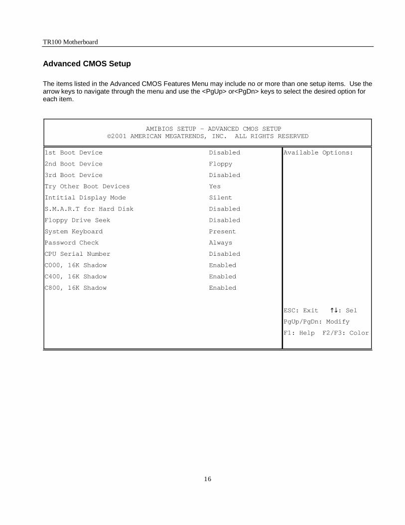
Advanced CMOS Setup
The items listed in the Advanced CMOS Features Menu may include no or more than one setup items. Use the arrow keys to navigate through the menu and use the <PgUp> or<PgDn> keys to select the desired option for each item.
1st Boot Device Disabled Available Options:
2nd Boot Device Floppy
3rd Boot Device Disabled
Try Other Boot Devices Yes
Intitial Display Mode Silent
S.M.A.R.T for Hard Disk Disabled
Floppy Drive Seek Disabled
System Keyboard Present
Password Check Always
CPU Serial Number Disabled
C000, 16K Shadow Enabled
C400, 16K Shadow Enabled
C800, 16K Shadow Enabled
ESC: Exit KL: Sel
PgUp/PgDn: Modify
F1: Help F2/F3: Color
AMIBIOS SETUP - ADVANCED CMOS SETUP ©2001 AMERICAN MEGATRENDS, INC. ALL RIGHTS RESERVED

TR100 Motherboard
17
Advanced Chipset Setup
The items listed in the Advanced Chipset Setup Menu may include no or more than one setup items. Use the arrow keys to navigate through the menu and use the <PgUp> or<PgDn> keys to select the desired option for each item.
CPU Ratio Selection Locked
System Memory Frequency Auto
DRAM Refresh 15.6uS
DRAM Cycle time (SCLKs) 6/8
CAS# Latency (SCLKs) 3
RAS to CAS delay (SCLKs) 3
SDRAM RAS# Precharge (SCLKs) 3
AGP Aperture Size 64MB
CPU Latency Timer Enabled
USB Controller All USB Port
USB Device Legacy Support All Device
Local Memory Frequency 133Mhz
Initialize Display Cache Memory Enabled
Paging Mode Control Open
RAS-to-CAS Default
CAS Latency Slow
RAS Timing Slow ESC: Exit KL: Sel
RAS Precharge Timing Slow PgUp/PgDn: Modify
F1: Help F2/F3: Color
AMIBIOS SETUP - ADVANCED CHIPSET SETUP ©2001 AMERICAN MEGATRENDS, INC. ALL RIGHTS RESERVED

TR100 Motherboard
18
Power Management Setup
The items listed in the Power Management Setup Menu may include no or more than one setup items. Use the arrow keys to navigate through the menu and use the <PgUp> or<PgDn> keys to select the desired option for each item.
AMIBIOS SETUP – POWER MANAGEMENT SETUP ©2001 AMERICAN MEGATRENDS, INC. ALL RIGHTS RESERVED
ACPI Standby State S3/STR Available Options:
Power Management/APM Enabled
Suspend Time Out Disabled
Power Button Function On/Off
Restore on AC/Power Loss Last State
Resume on Ring Disabled
Resume on LAN Enabled
Resume On PME Enabled
Resume On RTC Alarm Disabled
Alarm Date 15
Alarm Hour 12
Alarm Minute 30
Alarm Second 30
ESC: Exit KL: Sel
PgUp/PgDn: Modify
F1: Help F2/F3: Color
TR100 Motherboard
19
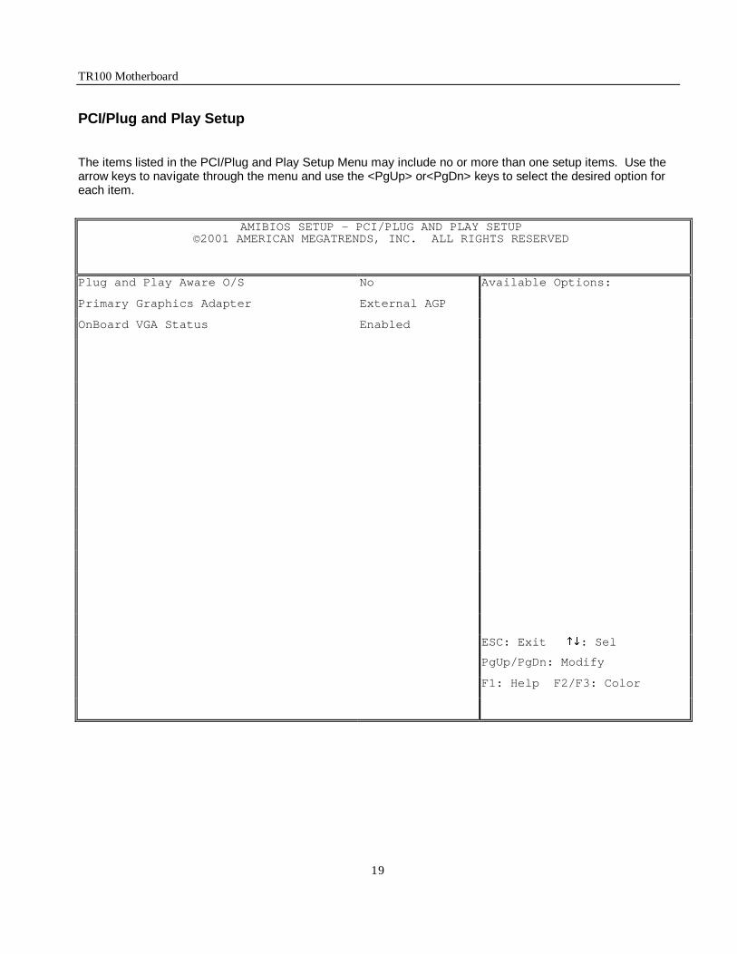
PCI/Plug and Play Setup
The items listed in the PCI/Plug and Play Setup Menu may include no or more than one setup items. Use the arrow keys to navigate through the menu and use the <PgUp> or<PgDn> keys to select the desired option for each item.
AMIBIOS SETUP – PCI/PLUG AND PLAY SETUP ©2001 AMERICAN MEGATRENDS, INC. ALL RIGHTS RESERVED
Plug and Play Aware O/S No Available Options:
Primary Graphics Adapter External AGP
OnBoard VGA Status Enabled
ESC: Exit KL: Sel
PgUp/PgDn: Modify
F1: Help F2/F3: Color

TR100 Motherboard
20
Peripheral Setup
The items listed in the Peripheral Setup Menu may include no or more than one setup items. Use the arrow keys to navigate through the menu and use the <PgUp> or<PgDn> keys to select the desired option for each item.
AMIBIOS SETUP – PERIPHERAL SETUP ©2001 AMERICAN MEGATRENDS, INC. ALL RIGHTS RESERVED
OnBoard IDE Both Available Options:
OnBoard AC’97 Audio Enabled
OnBoard FDC Auto
OnBoard Serial PortA Auto
OnBoard Serial PortB Auto
Serial PortB Mode Normal
IR Duplex Mode Half Duplex
IR Receiver Polarity Active Low
IR Xmitter Polarity Active Low
OnBoard Parallel Port Auto
Parallel Port Mode ECP
Parallel Port IRQ Auto
Parallel Port DMA Channel Auto
ESC: Exit KL: Sel
PgUp/PgDn: Modify
F1: Help F2/F3: Color

TR100 Motherboard
21
Hardware Monitor Setup
The items listed in the Hardware Monitor Setup may include no or more than one setup items. Use the arrow keys to navigate through the menu and use the <PgUp> or<PgDn> keys to select the desired option for each item.
AMIBIOS SETUP – HARDWARE MONITOR SETUP ©2001 AMERICAN MEGATRENDS, INC. ALL RIGHTS RESERVED
-= System Hardware Monitor =- Available Options:
CPU Temperature 40°C/104 °F
System Temperature 30°C/86 °F
CPU Fan Speed 3613 RPM
Chassis Fan Speed 0 RPM
Vccp (Processor) 1.717V
+12.0V 12.422V
+1.85V 1.872V
+5.0V 4.911V
+3.3V 3.233V
+2.5V 2.492V
+1.5V 1.509V
FAN Speed Control Disabled
Chassis Intrusion Disabled
ESC: Exit KL: Sel
PgUp/PgDn: Modify
F1: Help F2/F3: Color
TR100 Motherboard
22
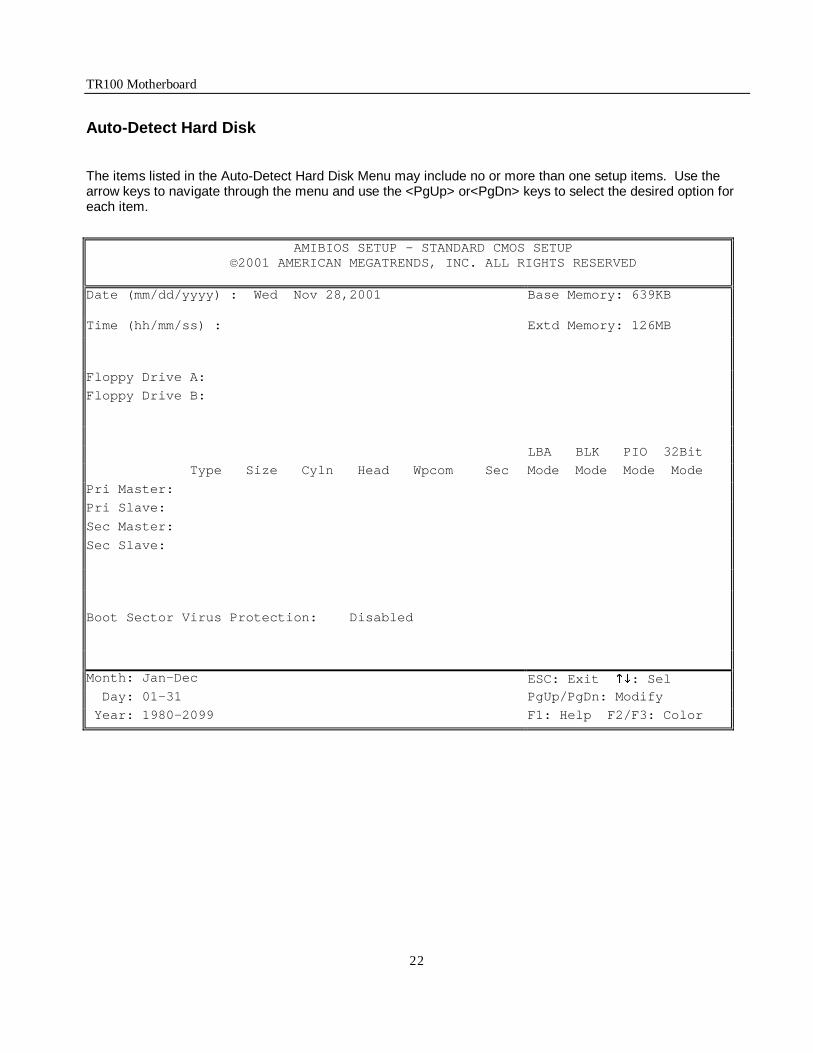
Auto-Detect Hard Disk
The items listed in the Auto-Detect Hard Disk Menu may include no or more than one setup items. Use the arrow keys to navigate through the menu and use the <PgUp> or<PgDn> keys to select the desired option for each item.
AMIBIOS SETUP - STANDARD CMOS SETUP ©2001 AMERICAN MEGATRENDS, INC. ALL RIGHTS RESERVED
Date (mm/dd/yyyy) : Wed Nov 28,2001 Base Memory: 639KB
Time (hh/mm/ss) : Extd Memory: 126MB
Floppy Drive A:
Floppy Drive B:
LBA BLK PIO 32Bit
Type Size Cyln Head Wpcom Sec Mode Mode Mode Mode
Pri Master:
Pri Slave:
Sec Master:
Sec Slave:
Boot Sector Virus Protection: Disabled
Month: Jan-Dec ESC: Exit KL: Sel Day: 01-31 PgUp/PgDn: Modify
Year: 1980-2099 F1: Help F2/F3: Color

TR100 Motherboard
23
Change User Password
The items listed in the Auto-Detect Hard Disk Menu may include no or more than one setup items. Use the arrow keys to navigate through the menu and use the <PgUp> or<PgDn> keys to select the desired option for each item.
AMI HIFLEX SETUP UTILITY - VERSION 1.37 ©2001 AMERICAN MEGATRENDS, INC. ALL RIGHTS RESERVED
TR100 BIOS Rev: 1.00
Standard CMOS Features
Advanced CMOS Features
Advanced Chipset Features
Power Management Setup
PCI / Plug and Play Setup
Peripheral Setup
Hardware Monitor Setup
Auto-Detect Hard Disks
Change User Password
Change Supervisor Password
Auto Configuration with Optimal Setting
Auto Configuration with Fail Safe Settings
Save Settings and Exit
Exit without Saving
Change user password
ESC: Exit KL: Sel F2/F3: Color F10: Save and Exit
Enter new user password: _

TR100 Motherboard
24
Change Supervisor Password
The items listed in the Change Supervisor Password Menu may include no or more than one setup items. Use the arrow keys to navigate through the menu and use the <PgUp> or<PgDn> keys to select the desired option for each item.
AMI HIFLEX SETUP UTILITY - VERSION 1.37 ©2001 AMERICAN MEGATRENDS, INC. ALL RIGHTS RESERVED
TR100 BIOS Rev: 1.00
Standard CMOS Features
Advanced CMOS Features
Advanced Chipset Features
Power Management Setup
PCI / Plug and Play Setup
Peripheral Setup
Hardware Monitor Setup
Auto-Detect Hard Disks
Change User Password
Change Supervisor Password
Auto Configuration with Optimal Setting
Auto Configuration with Fail Safe Settings
Save Settings and Exit
Exit without Saving
Change the supervisor password
ESC: Exit KL: Sel F2/F3: Color F10: Save and Exit
Enter new supervisor password: _
TR100 Motherboard
25
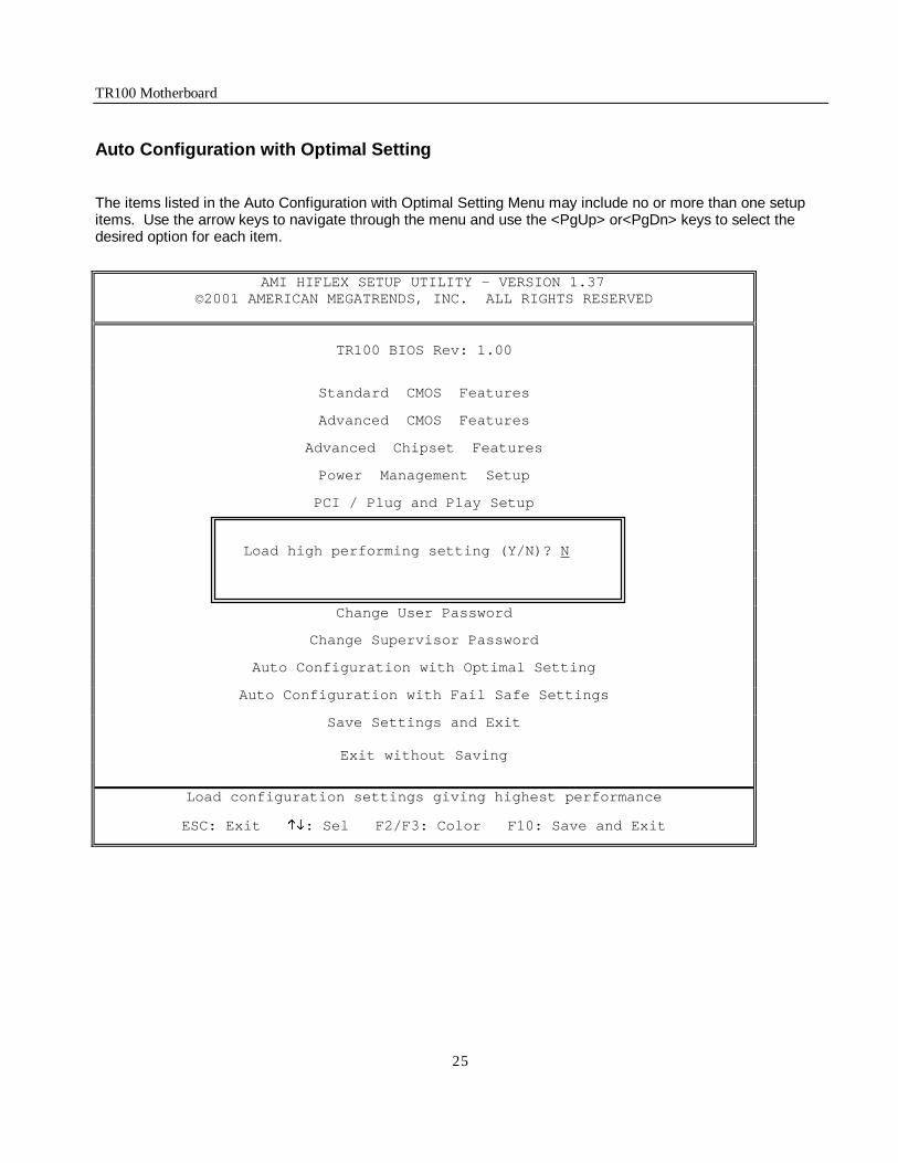
Auto Configuration with Optimal Setting
The items listed in the Auto Configuration with Optimal Setting Menu may include no or more than one setup items. Use the arrow keys to navigate through the menu and use the <PgUp> or<PgDn> keys to select the desired option for each item.
AMI HIFLEX SETUP UTILITY - VERSION 1.37 ©2001 AMERICAN MEGATRENDS, INC. ALL RIGHTS RESERVED
TR100 BIOS Rev: 1.00
Standard CMOS Features
Advanced CMOS Features
Advanced Chipset Features
Power Management Setup
PCI / Plug and Play Setup
Peripheral Setup
Hardware Monitor Setup
Auto-Detect Hard Disks
Change User Password
Change Supervisor Password
Auto Configuration with Optimal Setting
Auto Configuration with Fail Safe Settings
Save Settings and Exit
Exit without Saving
Load configuration settings giving highest performance
ESC: Exit KL: Sel F2/F3: Color F10: Save and Exit
Load high performing setting (Y/N)? N

TR100 Motherboard
26
Auto Configuration with Fail Safe Settings
The items listed in the Auto Configuration with Fail Safe Settings Menu may include no or more than one setup items. Use the arrow keys to navigate through the menu and use the <PgUp> or<PgDn> keys to select the desired option for each item.
AMI HIFLEX SETUP UTILITY - VERSION 1.37
©2001 AMERICAN MEGATRENDS, INC. ALL RIGHTS RESERVED
TR100 BIOS Rev: 1.00
Standard CMOS Features
Advanced CMOS Features
Advanced Chipset Features
Power Management Setup
PCI / Plug and Play Setup
Peripheral Setup
Hardware Monitor Setup
Auto-Detect Hard Disks
Change User Password
Change Supervisor Password
Auto Configuration with Optimal Setting
Auto Configuration with Fail Safe Settings
Save Settings and Exit
Exit without Saving
Load failsafe configuration settings
ESC: Exit KL: Sel F2/F3: Color F10: Save and Exit
Load failsafe settings (Y/N)? N

TR100 Motherboard
27
Save Settings and Exit
The items listed in the Save Settings and Exit Menu may include no or more than one setup items. Use the arrow keys to navigate through the menu and use the <PgUp> or<PgDn> keys to select the desired option for each item.
AMI HIFLEX SETUP UTILITY - VERSION 1.37 ©2001 AMERICAN MEGATRENDS, INC. ALL RIGHTS RESERVED
TR100 BIOS Rev: 1.00
Standard CMOS Features
Advanced CMOS Features
Advanced Chipset Features
Power Management Setup
PCI / Plug and Play Setup
Peripheral Setup
Hardware Monitor Setup
Auto-Detect Hard Disks
Change User Password
Change Supervisor Password
Auto Configuration with Optimal Setting
Auto Configuration with Fail Safe Settings
Save Settings and Exit
Exit without Saving
Write the current settings to CMOS and exit
ESC: Exit KL: Sel F2/F3: Color F10: Save and Exit
Save current settings and exit (Y/N)? Y

TR100 Motherboard
28
Exit without Saving
The items listed in the Exit without Saving Features Menu may include no or more than one setup items. Use the arrow keys to navigate through the menu and use the <PgUp> or<PgDn> keys to select the desired option for each item.
AMI HIFLEX SETUP UTILITY - VERSION 1.37
©2001 AMERICAN MEGATRENDS, INC. ALL RIGHTS RESERVED
TR100 BIOS Rev: 1.00
Standard CMOS Features
Advanced CMOS Features
Advanced Chipset Features
Power Management Setup
PCI / Plug and Play Setup
Peripheral Setup
Hardware Monitor Setup
Auto-Detect Hard Disks
Change User Password
Change Supervisor Password
Auto Configuration with Optimal Setting
Auto Configuration with Fail Safe Settings
Save Settings and Exit
Exit without Saving
Exit without saving the current settings
ESC: Exit KL: Sel F2/F3: Color F10: Save and Exit
Quit without saving (Y/N)? N

TR100 Motherboard
29
NOTES