tr 103 386 - v1.1.1 - methods for testing and ... · etsi tr 103 386 v1.1.1 (2016-04) methods for...
TRANSCRIPT

ETSI TR 103 386 V1.1.1 (2016-04)
Methods for Testing and Specification (MTS); Deployment of Model-Based Automated
Testing Infrastructure in a Cloud
TECHNICAL REPORT

ETSI
ETSI TR 103 386 V1.1.1 (2016-04) 2
Reference DTR/MTS-103386
Keywords cloud, testing
ETSI
650 Route des Lucioles F-06921 Sophia Antipolis Cedex - FRANCE
Tel.: +33 4 92 94 42 00 Fax: +33 4 93 65 47 16
Siret N° 348 623 562 00017 - NAF 742 C
Association à but non lucratif enregistrée à la Sous-Préfecture de Grasse (06) N° 7803/88
Important notice
The present document can be downloaded from: http://www.etsi.org/standards-search
The present document may be made available in electronic versions and/or in print. The content of any electronic and/or print versions of the present document shall not be modified without the prior written authorization of ETSI. In case of any
existing or perceived difference in contents between such versions and/or in print, the only prevailing document is the print of the Portable Document Format (PDF) version kept on a specific network drive within ETSI Secretariat.
Users of the present document should be aware that the document may be subject to revision or change of status. Information on the current status of this and other ETSI documents is available at
https://portal.etsi.org/TB/ETSIDeliverableStatus.aspx
If you find errors in the present document, please send your comment to one of the following services: https://portal.etsi.org/People/CommiteeSupportStaff.aspx
Copyright Notification
No part may be reproduced or utilized in any form or by any means, electronic or mechanical, including photocopying and microfilm except as authorized by written permission of ETSI.
The content of the PDF version shall not be modified without the written authorization of ETSI. The copyright and the foregoing restriction extend to reproduction in all media.
© European Telecommunications Standards Institute 2016.
All rights reserved.
DECTTM, PLUGTESTSTM, UMTSTM and the ETSI logo are Trade Marks of ETSI registered for the benefit of its Members. 3GPPTM and LTE™ are Trade Marks of ETSI registered for the benefit of its Members and
of the 3GPP Organizational Partners. GSM® and the GSM logo are Trade Marks registered and owned by the GSM Association.
ETSI
ETSI TR 103 386 V1.1.1 (2016-04) 3
Contents Intellectual Property Rights ................................................................................................................................ 5
Foreword ............................................................................................................................................................. 5
Modal verbs terminology .................................................................................................................................... 5
1 Scope ........................................................................................................................................................ 6
2 References ................................................................................................................................................ 6
2.1 Normative references ......................................................................................................................................... 6
2.2 Informative references ........................................................................................................................................ 6
3 Definitions and abbreviations ................................................................................................................... 8
3.1 Definitions .......................................................................................................................................................... 8
3.2 Abbreviations ................................................................................................................................................... 11
4 An integrated framework for testing automation on a cloud infrastructure ........................................... 13
4.0 Overview of the approach ................................................................................................................................ 13
4.1 Roles, relationships and interactions among TaaS users .................................................................................. 13
4.2 End user services .............................................................................................................................................. 15
5 End user use cases .................................................................................................................................. 16
5.0 Considered end user use cases .......................................................................................................................... 16
5.1 Direct test execution use case ........................................................................................................................... 17
5.1.0 Description .................................................................................................................................................. 17
5.1.1 Direct test execution use case TaaS sequence diagram............................................................................... 17
5.2 Manual test design use case .............................................................................................................................. 20
5.2.0 Description .................................................................................................................................................. 20
5.2.1 Manual test design use case TaaS sequence diagram ................................................................................. 22
5.3 Automated test design use case ........................................................................................................................ 23
5.3.0 Description .................................................................................................................................................. 23
5.3.1 Automated test design use case TaaS sequence diagram ............................................................................ 24
6 Representation of System models in TPaaS ........................................................................................... 25
6.0 Approaches to formal test descriptions ............................................................................................................ 25
6.1 MDSL conceptual model .................................................................................................................................. 26
6.1.0 Introduction................................................................................................................................................. 26
6.1.1 Test Planning Concept ................................................................................................................................ 26
6.1.2 Test Analysis Concepts ............................................................................................................................... 27
6.1.3 Test Design Concepts ................................................................................................................................. 29
6.1.4 Test Case Concepts ..................................................................................................................................... 29
6.1.5 Test Data Concepts ..................................................................................................................................... 30
6.1.6 Test Derivation Concepts ............................................................................................................................ 31
6.1.7 Refined Test Design Concepts .................................................................................................................... 33
6.1.8 Test Scheduling Concepts ........................................................................................................................... 34
6.2 Realisation as UML Profiles ............................................................................................................................ 35
6.2.0 Introduction................................................................................................................................................. 35
6.2.1 Test Planning Concepts Implementation .................................................................................................... 36
6.2.2 Test Requirement Implementation .............................................................................................................. 36
6.2.3 Test Object Implementation ........................................................................................................................ 36
6.2.4 Test Component Implementation ................................................................................................................ 36
6.2.5 SUT Implementation................................................................................................................................... 36
6.2.6 Test Configuration Implementation ............................................................................................................ 37
6.2.7 Test Case Implementation .......................................................................................................................... 37
6.2.8 Precondition Implementation ...................................................................................................................... 37
6.2.9 Postcondition Implementation .................................................................................................................... 37
6.2.10 Parameter Implementation .......................................................................................................................... 37
6.2.11 Stimulus Implementation ............................................................................................................................ 37
6.2.12 Response Implementation ........................................................................................................................... 37
6.2.13 Verdict Implementation .............................................................................................................................. 37
6.2.14 Test Design Model Implementation ............................................................................................................ 37
6.2.15 TestData Implementation ............................................................................................................................ 37

ETSI
ETSI TR 103 386 V1.1.1 (2016-04) 4
6.2.16 DataPartition Implementation ..................................................................................................................... 38
6.2.17 TestDataValue Implementation .................................................................................................................. 38
6.2.18 DataPool Implementation ........................................................................................................................... 38
6.2.19 Test Suite Implementation .......................................................................................................................... 38
6.2.20 Test Procedure Implementation .................................................................................................................. 38
6.2.21 Scheduling Specification Implementation .................................................................................................. 38
6.3 Constraints on the MIDAS DSL ....................................................................................................................... 39
6.3.0 Introduction................................................................................................................................................. 39
6.3.1 TestConfiguration/TestContext Constraints ............................................................................................... 39
6.3.2 TestCase Constraints................................................................................................................................... 39
6.3.3 TestProcedure Constraints .......................................................................................................................... 42
6.4 MDSL Validator ............................................................................................................................................... 42
6.5 TTCN-3 Generator ........................................................................................................................................... 43
6.6 SCA4SAUT approach to system modelling ..................................................................................................... 44
6.6.0 Introduction................................................................................................................................................. 44
6.6.1 Overview of the SCA4SAUT model .......................................................................................................... 45
6.6.2 Introduction to the SCA Assembly notation ............................................................................................... 46
7 Deployment of the TPaaS on the public cloud infrastructure ................................................................ 49
7.0 Development and production frameworks ....................................................................................................... 49
7.1 Integration of test methods on the TPaaS platform .......................................................................................... 49
7.1.0 Introduction................................................................................................................................................. 49
7.1.1 The Database structure for the MIDAS TPaaS ........................................................................................... 50
7.1.2 The storage file system for MIDAS TPaaS ................................................................................................ 52
7.2 Implemented facilities ...................................................................................................................................... 52
7.2.1 Development Environment (devenv_vm) ................................................................................................... 52
7.2.2 Production Environment (prodenv_multivm) ............................................................................................. 53
Annex A: End User Use Case Examples .............................................................................................. 56
A.1 Direct Execution Use Case Example: IMS Conformance testing .......................................................... 56
A.1.0 Overview .......................................................................................................................................................... 56
A.1.1 IMS as SUT ...................................................................................................................................................... 56
A.1.2 Test configuration............................................................................................................................................. 57
A.1.2.1 SUT architecture ......................................................................................................................................... 57
A.1.2.2 Message flow scenarios .............................................................................................................................. 58
A.1.2.3 Test suite structure ...................................................................................................................................... 59
A.1.3 Direct execution procedures taken within TPaaS ............................................................................................. 59
A.1.4 Lesson learned from direct execution use case ................................................................................................. 61
A.2 Manual test design example - SCM Pilot ............................................................................................... 62
A.2.0 Overview .......................................................................................................................................................... 62
A.2.1 SCM Pilot ......................................................................................................................................................... 62
A.2.2 Test configuration............................................................................................................................................. 65
A.2.3 Message flow scenarios .................................................................................................................................... 70
A.2.4 Manual execution ............................................................................................................................................. 74
A.2.5 Experiences ...................................................................................................................................................... 75
A.3 Automated test design example - e-Health Pilot .................................................................................... 77
A.3.0 Overview .......................................................................................................................................................... 77
A.3.1 e-Health Pilot .................................................................................................................................................... 77
A.3.2 Test configuration............................................................................................................................................. 79
A.3.3 Message flow scenarios .................................................................................................................................... 82
A.3.4 Automated execution ........................................................................................................................................ 84
A.3.5 Experiences ...................................................................................................................................................... 85
History .............................................................................................................................................................. 87

ETSI
ETSI TR 103 386 V1.1.1 (2016-04) 5
Intellectual Property Rights
IPRs essential or potentially essential to the present document may have been declared to ETSI. The information pertaining to these essential IPRs, if any, is publicly available for ETSI members and non-members, and can be found in ETSI SR 000 314: "Intellectual Property Rights (IPRs); Essential, or potentially Essential, IPRs notified to ETSI in respect of ETSI standards", which is available from the ETSI Secretariat. Latest updates are available on the ETSI Web server (https://ipr.etsi.org/).
Pursuant to the ETSI IPR Policy, no investigation, including IPR searches, has been carried out by ETSI. No guarantee can be given as to the existence of other IPRs not referenced in ETSI SR 000 314 (or the updates on the ETSI Web server) which are, or may be, or may become, essential to the present document.
Foreword This Technical Report (TR) has been produced by ETSI Technical Committee Methods for Testing and Specification (MTS).
Modal verbs terminology In the present document "shall", "shall not", "should", "should not", "may", "need not", "will", "will not", "can" and "cannot" are to be interpreted as described in clause 3.2 of the ETSI Drafting Rules (Verbal forms for the expression of provisions).
"must" and "must not" are NOT allowed in ETSI deliverables except when used in direct citation.

ETSI
ETSI TR 103 386 V1.1.1 (2016-04) 6
1 Scope The present document provides an overview of the approach taken within the EU-funded research project called MIDAS to design, build and deploy an integrated framework for testing automation that will be available as a Test as a Service (TaaS) on a Cloud infrastructure, and which covers key testing activities: test suite generation, test execution, scheduling, evaluation and test results arbitration. While MIDAS is focused on the test automation for Service Oriented Architecture (SOA), the testing methods and technologies that are investigated and prototyped within the project can be generalized to a greater degree and can be applied not only to SOA System Under Test (SUT), but also to SUTs in other domains, e.g. Automotive, Telecommunications, Machine-to-Machine services. Such broader application relates particularly to model-based test design and test suite generation, model checking of choreographies for sound interaction of test scenarios, fuzzing for security testing, usage-based testing, probabilistic inference reasoning for test evaluation and scheduling.
2 References
2.1 Normative references References are either specific (identified by date of publication and/or edition number or version number) or non-specific. For specific references, only the cited version applies. For non-specific references, the latest version of the referenced document (including any amendments) applies.
Referenced documents which are not found to be publicly available in the expected location might be found at https://docbox.etsi.org/Reference/.
NOTE: While any hyperlinks included in this clause were valid at the time of publication, ETSI cannot guarantee their long term validity.
The following referenced documents are necessary for the application of the present document.
Not applicable.
2.2 Informative references
References are either specific (identified by date of publication and/or edition number or version number) or non-specific. For specific references, only the cited version applies. For non-specific references, the latest version of the referenced document (including any amendments) applies.
NOTE: While any hyperlinks included in this clause were valid at the time of publication, ETSI cannot guarantee their long term validity.
The following referenced documents are not necessary for the application of the present document but they assist the user with regard to a particular subject area.
[i.1] ETSI ES 202 951: "Methods for Testing and Specification (MTS); Model-Based Testing (MBT); Requirements for Modelling Notations".
[i.2] ETSI ES 203 119: "Methods for Testing and Specification (MTS); The Test Description Language (TDL); Specification of the Abstract Syntax and Associated Semantics".
[i.3] MIDAS Deliverable D6.1.WP6 (2014): "Analysis of required functionalities and available public Cloud services".
[i.4] MIDAS Deliverable D6.3.WP6 (2014): "The basic MIDAS platform and the integrated test evaluation, planning and scheduling macro-component".
[i.5] ISO/IEC 9126-1 (2001): "Software engineering -- Product quality".
[i.6] ISO 9001 (2005): "Quality Management Systems -- Requirements".
[i.7] ISO/IEC/IEEE™ 29119: "Software Testing Standard".
NOTE: Available at http://www.softwaretestingstandard.org.

ETSI
ETSI TR 103 386 V1.1.1 (2016-04) 7
[i.8] UTP-1-2 (2013). UML testing profile (UTP) version 1.2. Tech. Rep. formal/2013-04-03, Object Management Group.
[i.9] International Software Testing Qualifications Board (ISTQB): ISTQB/GTB standard glossary for testing terms.
NOTE: Available at http://www.istqb.org/downloads/send/40-glossary-archive/180-istqb®-glossary-of-testing-terms.html.
[i.10] Object Management Group (OMG): Business Motivation Model (BMM).
NOTE: Available at http://www.omg.org/spec/BMM.
[i.11] IEEE™ 610.12 (1990): "IEEE Standard Glossary of Software Engineering Terminology".
[i.12] MIDAS Deliverable D2.1 (2013): "Requirements for automatically testable services and services architectures".
[i.13] ETSI TS 102 790-1: "Core Network and Interoperability Testing (INT); IMS specific use of Session Initiation Protocol (SIP) and Session Description Protocol (SDP); Conformance Testing; (3GPP Release 10); Part 1: Protocol Implementation Conformance Statement (PICS)".
[i.14] ETSI TS 102 790-2: "Core Network and Interoperability Testing (INT); IMS specific use of Session Initiation Protocol (SIP) and Session Description Protocol (SDP); Conformance Testing; (3GPP Release 10); Part 2: Test Suite Structure (TSS) and Test Purposes (TP)".
[i.15] ETSI TS 102 790-3: "Core Network and Interoperability Testing (INT); IMS specific use of Session Initiation Protocol (SIP) and Session Description Protocol (SDP); Conformance Testing; (3GPP Release 10); Part 3: Abstract Test Suite (ATS) and partial Protocol Implementation eXtra Information for Testing (PIXIT) proforma specification".
[i.16] ETSI TS 123 228: "Digital cellular telecommunications system (Phase 2+); Universal Mobile Telecommunications System (UMTS); LTE; IP Multimedia Subsystem (IMS); Stage 2 (3GPP TS 23.228)".
[i.17] ETSI TS 124 229: "Digital cellular telecommunications system (Phase 2+); Universal Mobile Telecommunications System (UMTS); LTE; IP multimedia call control protocol based on Session Initiation Protocol (SIP) and Session Description Protocol (SDP); Stage 3 (3GPP TS 24.229)".
[i.18] SCA-AM-V1-0 (2007). Service component architecture assembly model specification version 1.0. Tech. rep., OSOA.
[i.19] SCA-AM-V1-1 (2011). Service component architecture assembly model specification version 1.1. Tech. Rep. OASIS Committee Specification Draft 09 / Public Review Draft 04, OASIS.
[i.20] SoaML-1-0-1 (2012). Service Oriented Architecture Modeling Language (SoaML) Specification, Version 1.0.1. formal-12-05-10. Object Management Group.
[i.21] SOAP-1-1 (2000). Simple object access protocol (SOAP) 1.1. Tech. Rep. W3C Note 08 May 2000, World Wide Web Consortium.
[i.22] WSDL-1-1 (2001). Web service definition language (WSDL) 1.1. Tech. Rep. W3C Note 15 March 2001, World Wide Web Consortium.
[i.23] XML-Infoset (2004). XML information set (second edition). Tech. Rep. W3C Recommendation 4 February 2004, World Wide Web Consortium.
[i.24] XPath-2-0 (2010). XML path language (XPath) 2.0 (second edition). Tech. rep., World Wide Web Consortium. W3C Recommendation 14 December 2010, World Wide Web Consortium.
[i.25] XSD-1-Structures (2004). XML schema part 1: Structures second edition. Tech. Rep. W3C Recommendation 28 October 2004, World Wide Web Consortium.
[i.26] MIDAS Deliverable (2014): "SAUT Construction Model Specification Service Component Architecture for Services Architecture Under Test (SCA4SAUT) - V. 1.2".

ETSI
ETSI TR 103 386 V1.1.1 (2016-04) 8
[i.27] IEEE™ 829: "IEEE Standard for Software and System Test Documentation".
[i.28] ETSI TR 102 840: "Methods for Testing and Specifications (MTS); Model-based testing in standardisation".
[i.29] ETSI ES 201 873 (all parts): "Methods for Testing and Specification (MTS) The Testing and Test Control Notation version 3".
[i.30] ISO/IEC 9646-1: "Information Technology -- Open Systems Interconnection -- Conformance testing methodology -- Part 1: General concepts".
[i.31] ISO 28000: "Specification for security management systems for the s[upply chain".
[i.32] ISO 9000: "Quality management systems -- Fundamentals and vocabulary".
[i.33] Supply Chain Operations Reference model (SCOR).
NOTE: Available at http://www.apics.org/sites/apics-supply-chain-council/frameworks/scor.
[i.34] GS1: "Logistics Interoperability Model (LIM)".
NOTE: Available at http://www.gs1.org/lim.
[i.35] OMG RLUS™: "Retrieve, Locate And Update Service™ (RLUS™)".
NOTE: Available at http://www.omg.org/spec/RLUS/.
[i.36] OMG IXS™: "Identity Cross-Reference Service™ (IXS™)".
NOTE: Available at http://www.omg.org/spec/IXS/.
[i.37] OMG CTS2™: "Documents Associated With Common Terminology Services 2™ (CTS2™)".
NOTE: Available at http://www.omg.org/spec/CTS2/1.0/.
[i.38] HL7® International: "CDA® Release 2".
3 Definitions and abbreviations
3.1 Definitions For the purposes of the present document, the following terms and definitions apply:
accuracy: capability of the software product to provide the right or agreed results or effects with the needed degree of precision
NOTE: See ISO/IEC 9126 [i.5].
black-box testing: testing, either functional or non-functional, without reference to the internal structure of the component or system
NOTE: See ISTQB Glossary [i.9]
cloud computing: model for enabling service user's ubiquitous, convenient, on-demand network access to a shared pool of configurable computing resources (e.g. networks, servers, storage, applications and services) that can be rapidly provisioned and released with minimal management effort or service provider interaction
cloud provider: provider that offers storage or software services available via a private or public network
NOTE: The storage and software are available for access via the Internet. The cloud provider manages the infrastructure and platforms on which the applications run.
coverage: the degree, expressed as a percentage, to which a specified coverage item has been exercised by a test suite
NOTE: See ISTQB Glossary [i.9].
ETSI
ETSI TR 103 386 V1.1.1 (2016-04) 9
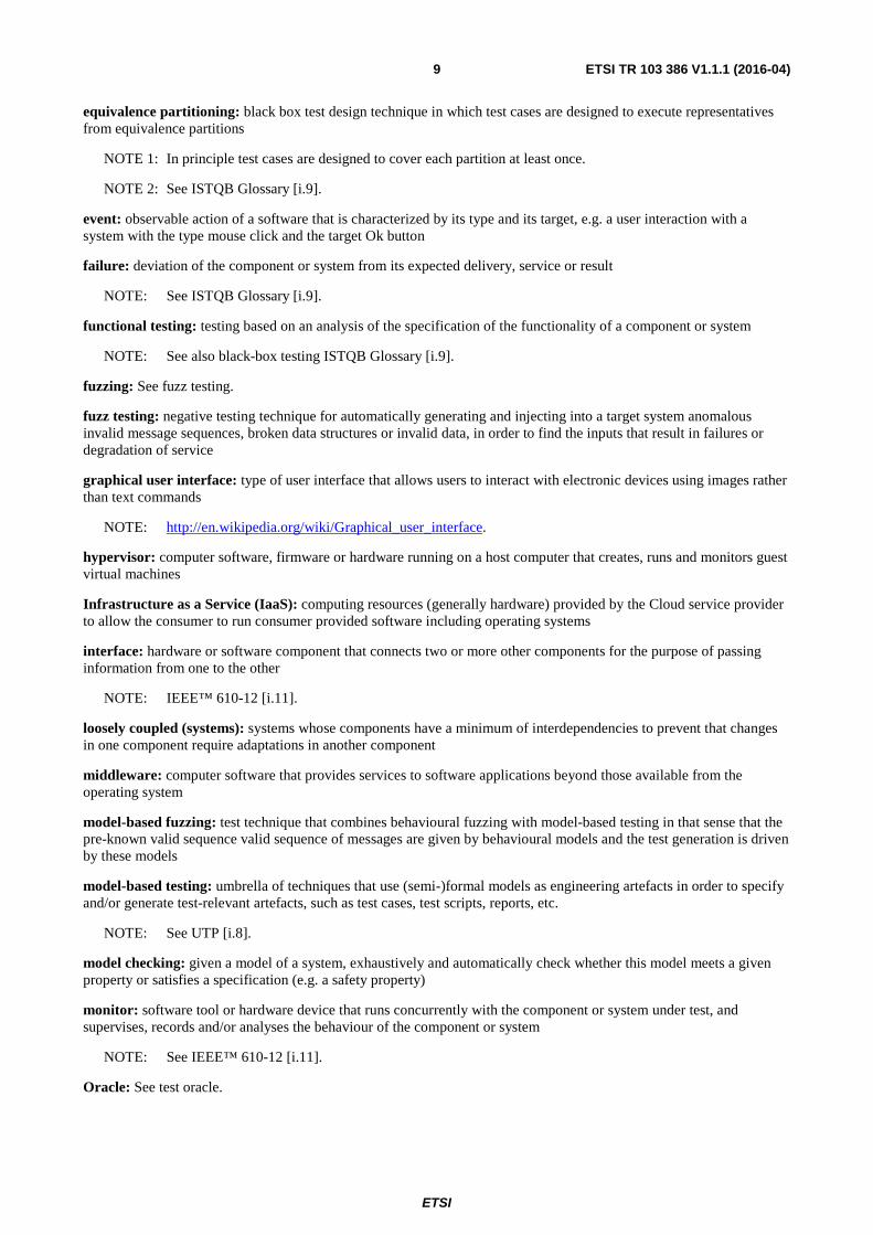
equivalence partitioning: black box test design technique in which test cases are designed to execute representatives from equivalence partitions
NOTE 1: In principle test cases are designed to cover each partition at least once.
NOTE 2: See ISTQB Glossary [i.9].
event: observable action of a software that is characterized by its type and its target, e.g. a user interaction with a system with the type mouse click and the target Ok button
failure: deviation of the component or system from its expected delivery, service or result
NOTE: See ISTQB Glossary [i.9].
functional testing: testing based on an analysis of the specification of the functionality of a component or system
NOTE: See also black-box testing ISTQB Glossary [i.9].
fuzzing: See fuzz testing.
fuzz testing: negative testing technique for automatically generating and injecting into a target system anomalous invalid message sequences, broken data structures or invalid data, in order to find the inputs that result in failures or degradation of service
graphical user interface: type of user interface that allows users to interact with electronic devices using images rather than text commands
NOTE: http://en.wikipedia.org/wiki/Graphical_user_interface.
hypervisor: computer software, firmware or hardware running on a host computer that creates, runs and monitors guest virtual machines
Infrastructure as a Service (IaaS): computing resources (generally hardware) provided by the Cloud service provider to allow the consumer to run consumer provided software including operating systems
interface: hardware or software component that connects two or more other components for the purpose of passing information from one to the other
NOTE: IEEE™ 610-12 [i.11].
loosely coupled (systems): systems whose components have a minimum of interdependencies to prevent that changes in one component require adaptations in another component
middleware: computer software that provides services to software applications beyond those available from the operating system
model-based fuzzing: test technique that combines behavioural fuzzing with model-based testing in that sense that the pre-known valid sequence valid sequence of messages are given by behavioural models and the test generation is driven by these models
model-based testing: umbrella of techniques that use (semi-)formal models as engineering artefacts in order to specify and/or generate test-relevant artefacts, such as test cases, test scripts, reports, etc.
NOTE: See UTP [i.8].
model checking: given a model of a system, exhaustively and automatically check whether this model meets a given property or satisfies a specification (e.g. a safety property)
monitor: software tool or hardware device that runs concurrently with the component or system under test, and supervises, records and/or analyses the behaviour of the component or system
NOTE: See IEEE™ 610-12 [i.11].
Oracle: See test oracle.

ETSI
ETSI TR 103 386 V1.1.1 (2016-04) 10
public cloud: cloud infrastructure is provisioned for open use by the general public
NOTE: It can be owned, managed, and operated by a business, academic, or government organization, or some combination of them. It exists on the premises of the cloud provider.
regression testing: selective retesting of a system or component to verify that modifications have not caused unintended effects and that the system or component still complies with its specified requirements
NOTE: See IEEE™ 610-12 [i.11].
security testing: process to determine that an information system protects data and maintains functionality as intended
service: activity that has an effect in the real/digital world, carried out by a system acting as a service provider for or on behalf of another system acting as a service consumer
Service Oriented Architecture (SOA): software architecture of services, policies, practices and frameworks in which components can be reused and repurposed rapidly in order to achieve shared and new functionality
Software as a Service (SaaS): capability provided to the consumer is to use the provider's applications running on a cloud infrastructure
NOTE: The applications are accessible from various client devices through either a thin client interface, such as a web browser (e.g. web-based email), or a program interface. The consumer does not manage or control the underlying cloud infrastructure including network, servers, operating systems, storage, or even individual application capabilities, with the possible exception of limited user-specific application configuration settings.
software quality: degree to which a software product fulfils its functional and non-functional requirements (IEEE™ 610-12 [i.11] under the term quality)
software testing: the process concerned with planning, preparation and evaluation of software products and related work products to determine that they satisfy specified requirements, to demonstrate that they are fit for purpose and to detect defects
System Under Test (SUT): real open system in which the implementation under test resides (ETSI ES 202 951 [i.1])
test arbitration: testing activity that assigns a test verdict to a test execution run
NOTE: Requires a test oracle.
test case: set of input values, execution preconditions, expected results and execution post conditions, developed for a particular objective or test condition, such as to exercise a particular program path or to verify compliance with a specific requirement
test case generator: software tool that accepts as input source code, test criteria, specifications, or data structure definitions; uses these inputs to generate test input data; and, sometimes, determines expected results
NOTE See IEEE™ 610-12 [i.11].
test component: part of a test configuration used to communicate with the System Under Test (SUT) and other test components
test configuration: specification of a set of components that contains at least one tester component and one system under test component plus their interconnections via gates and connections
test environment: environment containing hardware, instrumentation, simulators, software tools, and other support elements needed to conduct a test
NOTE: See IEEE™ 610-12 [i.11].
test execution: process of running a test on the component or system under test, producing actual result(s)
NOTE: See ISTQB Glossary [i.9].
test generation: automated activity for deriving test-relevant artefacts such as test cases, test data, test oracle test code

ETSI
ETSI TR 103 386 V1.1.1 (2016-04) 11
test log: chronological record of relevant details about the execution of tests (IEEE™ 829 [i.27])
NOTE: See ISTQB Glossary [i.9].
test model: model that specifies various testing aspects, such as test objectives, test plans, test architecture, test cases, test data, test directives etc.
NOTE: See UTP [i.8].
test requirement: item or event of a component or system that could be verified by one or more test cases, e.g. a function, transaction, feature, quality attribute, or structural element
NOTE: See ISTQB Glossary [i.9].
test run: execution of a test on a specific version of the test object
NOTE: See ISTQB Glossary [i.9].
test schedule: list of activities, tasks or events of the test process, identifying their intended start and finish dates and/or times, and interdependencies
NOTE: See ISTQB Glossary [i.9].
test suite: set of several test cases for a component or system under test, where the post condition of one test is often used as the precondition for the next one
NOTE: See ISTQB Glossary [i.9].
Testing as a Service (TaaS): cloud service that offers functionality for software testing in form of a Web service
Testing Platform as a Service (TPaaS): integrated testing platform available on demand (i.e. on a self-provisioning, pay-per-use, elastic basis) that is deployed on a public Cloud and accessible over the Internet as a multi-tenancy SaaS from an end-user perspective
validation: confirmation by examination and through provision of objective evidence that the requirements for a specific intended use or application have been fulfilled
NOTE: See ISO 9000 [i.32].
Virtual Machine (VM): software implementation of a machine that executes programs like a physical machine
NOTE: It can be seen as a simulation of a machine (abstract or real) that is usually different from the target machine (where it is being simulated on).
Virtual Machine Image (VMI): software application combined with just enough operating system for it to run optimally in a virtual machine
NOTE: VMIs are intended to eliminate the installation, configuration and maintenance costs associated with running complex stacks of software.
virtualization: software that separates applications from the physical hardware on which they run, allowing a 'piece' of physical server to support one application, instead of requiring a full server
3.2 Abbreviations For the purposes of the present document, the following abbreviations apply:
API Application Program Interface AS Authentication Service ASN Abstract Syntax Notation ATS Abstract Test Suite AWS Amazon™ Web Services BMM Business Motivation Model BPEL Business Process Execution Language CN Core Network CSCF Call Server Control Function

ETSI
ETSI TR 103 386 V1.1.1 (2016-04) 12
DB Data Base DSL Domain Specific Language EFSM Extended Finite State Machine ETS Executable Test Suite EU European Union FSM Finite State Machine HSSP Healthcare Service Specification Program HTTP Hyper Text Transfer Protocol IaaS Infrastructure as a Service IBCF Interconnect Border Control Function IMS IP Multimedia Subsystem IP Internet Protocol ISTQB International Software Testing Qualifications Board IUT Implementation Under Test IXS™ Identity Cross-Reference Service LIM Logistics Interoperability Model MBT Model-Based Testing MBTA Model-Based Testing Approaches MDSL MIDAS DSL MIDAS Model and Inference Driven Automated testing of Services architectures MPI Master Patient Index MQ Management and Query OCL Object Constraint Language OMG Object Management Group PICS Protocol Implementation Conformance Statement PIM Platform Independent Model PIXIT Protocol Implementation eXtra Information for Testing PSM Platform Specific Model PSOIX Portable Operating System Interface RAM Random Access Memory RDBMS Relational Data Base Management System RDS Relational Database Service RLP Restful Lightweight Protocol RLUS™ Retrieve, Locate and Update Service ROI Return On Investment SaaS Software as a Service SAUT System Architecture Under Test SC Supply Chain SCA Service Component Architecture SCA4SAUT Service Component Architecture for Services Architecture Under Test SCM Supply Chain Management SCOR Supply Chain Operations Reference SCXML State Chart XML SDP Session Description Protocol SIP Session Initiation Protocol Session Description Protocol SLA Service Level Agreement SOA Service Oriented Architecture SOAP Service Oriented Architecture Protocol SUT System - Under Test TaaS Test as a Service TB Technical Body TDD Test Driven Development TDL Test Description Language TMC Technical Management Coordination TMD Test Method Developer TP Test Purposes TPaaS Testing Platform as a Service TS Test Suite TSD Test Scenario Definition TSS Test Suite Structure TTA Traditional Testing Approaches TTCN-3 Testing and Test Control Notation (version 3)

ETSI
ETSI TR 103 386 V1.1.1 (2016-04) 13
TTWB TTCN-3 Workbench UBT Usage Based Testing UE User Equipment UML Unified Modelling Language URI Uniform Resource Identifier UTP UML Testing Profile VM Virtual Machine VMI Virtual Machine Image VMM Virtual Machine Monitor WS Web Service WSDL Web Service Definition Language XDW Cross-enterprise Document Workflow XMI XML Metadata Interchange XML eXtended Markup Language XSD XML Schema Definition XTHM Cross-enterprise TeleHome Monitoring
4 An integrated framework for testing automation on a cloud infrastructure
4.0 Overview of the approach The present document provides an overview of the approach taken within the EU-funded research project called MIDAS to design, build and deploy an integrated framework for testing automation that will be available as a Test as a Service (TaaS) on a Cloud infrastructure, and which covers key testing activities: test suite generation, test execution, scheduling, evaluation and test results arbitration. While, MIDAS is focused on the test automation for Service Oriented Architecture (SOA), the testing methods and technologies that are investigated and prototyped within the project can be generalized to a greater degree and can be applied not only to SOA System Under Test (SUT), but also to SUTs in other domains, e.g. Automotive, Telecommunications, Machine-to-Machine services. Such broader application relates particularly to model-based test design and test suite generation, model checking of choreographies for sound interaction of test scenarios, fuzzing for security testing, usage-based testing, probabilistic inference reasoning for test evaluation and scheduling.
The MIDAS test automation approach is model-based, as defined in ETSI TR 102 840 [i.28]. The user specifies structural, functional and behavioural models of the SUT and testing models that specify the test domain (e.g. functional testing, security testing, usage-based testing) and the specific testing methods, practices and strategies to be applied. The test model structure and semantics applied in MIDAS project rely on the extension of the UML Testing Profile (UTP) [i.8].
The TaaS integrated test automation facility is designed and provided as an integrated Testing Platform as a Service (TPaaS) framework available on demand, i.e. on a self-provisioning, pay-per-use, elastic basis. For this reason, the TPaaS is deployed on a public cloud infrastructure and accessible over the Internet as a multi-tenancy Software as a Service (SaaS) from an end user perspective. TPaaS provides companies and end users with services to design, deploy and run their test cases without disclosing any information to the cloud provider, and without having to program the whole test procedures from scratch. The costs saving and easy accessibility of cloud's extremely large computing resources makes testing facility usage available to geographically distributed users, executing wide varieties of user scenarios, with a scalability range previously unattainable in traditional testing environments.
4.1 Roles, relationships and interactions among TaaS users Designed integrated TaaS framework has four classes of users, each one playing different roles in interacting with the TPaaS platform:
1) End users: they consist of users responsible for planning, designing, and conducting test campaigns on service architectures, and users responsible for the creation, administration, and deployment of the service architecture under test.
2) Test method developers: they consist of users responsible for designing and implementing test methods to be used for conducting test campaigns.

ETSI
ETSI TR 103 386 V1.1.1 (2016-04) 14
3) Administrators: they consist of users responsible for managing both the identification and authentication of end users and test method developers, and the TaaS facilities used by the administered users, including the accounting and billing of these facilities.
4) TaaS administrator: it is the responsible entity for the entire TaaS platform, and for managing any interaction with the selected cloud provider of the Infrastructure as a service (IaaS) platform for the TaaS development and operation. As such, he/she is responsible for the dynamic provisioning of all TaaS public functionalities and for configuring the underlying cloud resources and services for TaaS users, and for any interaction with the cloud IaaS provider.
End users and test method developers are conceptually grouped in logical facilities called respectively tenancies and labs that are users computing spaces managed by tenancy/lab administrators. Tenancies and labs are units of:
• end users identification and authentication;
• cloud resources allocation, accounting and billing;
• data and services ownership and access.
Each tenancy/lab needs to able to deal with its own cloud users, cloud resources, data and services in a private, sandboxed way.
The composition of relationships and interactions among users and facilities of the TPaaS are shown in Figure 1. As shown, the TPaaS can contain several tenancies (resp. labs), each one composed of several end users (resp. test method developers). Each tenancy (resp. lab) is managed by a tenancy admin (resp. lab admin) that interacts with the respective users, and it is responsible for creating user accounts and credentials for them.
It is assumed that the underlying cloud infrastructure/middleware is completely transparent to end users, while tenancy/lab administrators are aware only of cloud resources usage and billing, but they are not involved in their management or/and allocation.
Figure 1: Composition relationships and interactions among TaaS users
The TPaaS is provided and managed by a single entity, the TaaS admin, also known as the TPaaS provider. It is the only one responsible for:
• creating, deploying, managing, and disposing tenancies/labs on the TPaaS;
• interacting with the provider of the underlying cloud infrastructure;
• establishing and enforcing the rules of configuration of cloud resources and services for each tenancy/lab;
• monitoring the deployment of the TaaS services (end user, core and admin services) for each tenancy/lab.
All the cloud infrastructure features are completely hidden behind the TPaaS provider. All TaaS users just interact with the respective public APIs and services, published on the Internet through the TPaaS by the TaaS admin. The TaaS admin, in general, fixes the rules to use the TPaaS underlying resources and monitor their usage by the user applications.
ETSI
ETSI TR 103 386 V1.1.1 (2016-04) 15
It is assumed that before the creation of a tenancy/lab, the TaaS admin interacts with the tenancy/lab administrators to establish service level agreements (SLAs), i.e. legal contracts, between himself, as the TaaS service provider, and the tenancy/lab administrators as TaaS services consumers, where regulations, duties, payment policies concerning the usage of TaaS services and computing resources are stated. The TaaS offers one or a small number of "standard contracts". Hence, a contract template was envisioned as a pricing mechanism (how the tenancy/lab pays for the TaaS services) coupled with a resource allocation policy (how the TaaS admin pays the cloud provider). Conversely, the resource allocation policy can depend on the cloud provider.
The rest of the present document will concentrate mainly on the end users use cases and end user core services.
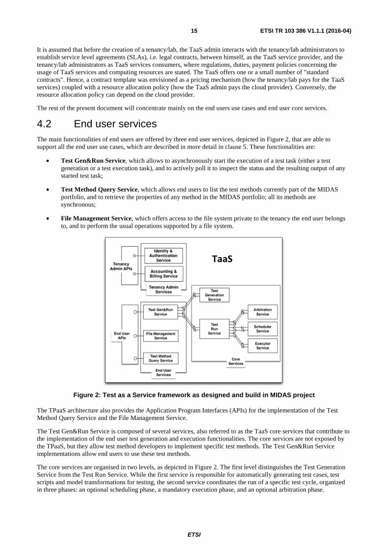
4.2 End user services The main functionalities of end users are offered by three end user services, depicted in Figure 2, that are able to support all the end user use cases, which are described in more detail in clause 5. These functionalities are:
• Test Gen&Run Service, which allows to asynchronously start the execution of a test task (either a test generation or a test execution task), and to actively poll it to inspect the status and the resulting output of any started test task;
• Test Method Query Service, which allows end users to list the test methods currently part of the MIDAS portfolio, and to retrieve the properties of any method in the MIDAS portfolio; all its methods are synchronous;
• File Management Service, which offers access to the file system private to the tenancy the end user belongs to, and to perform the usual operations supported by a file system.
Figure 2: Test as a Service framework as designed and build in MIDAS project
The TPaaS architecture also provides the Application Program Interfaces (APIs) for the implementation of the Test Method Query Service and the File Management Service.
The Test Gen&Run Service is composed of several services, also referred to as the TaaS core services that contribute to the implementation of the end user test generation and execution functionalities. The core services are not exposed by the TPaaS, but they allow test method developers to implement specific test methods. The Test Gen&Run Service implementations allow end users to use these test methods.
The core services are organised in two levels, as depicted in Figure 2. The first level distinguishes the Test Generation Service from the Test Run Service. While the first service is responsible for automatically generating test cases, test scripts and model transformations for testing, the second service coordinates the run of a specific test cycle, organized in three phases: an optional scheduling phase, a mandatory execution phase, and an optional arbitration phase.
TaaS

ETSI
ETSI TR 103 386 V1.1.1 (2016-04) 16
The Test Generation Service is provided by a Test Generation Container. Each container can include different modules as plug-ins, each of them implementing a specific test generation capability, with the same interface of the test generation service. Both Test Gen and Run Services are invoked asynchronously, and their outcome is notified to the Test Gen&Run Service through a notification, whose listener is provided by the Test Gen&Run Service.
The second level of the Test Gen&Run Service architecture concerns the Test Run Service. It includes three independent services: the Test Arbitration Service, the Test Scheduling Service, and the Test Executor Service. These services are provided by a corresponding container, as for the Test Generation Service and the Run Service. Also for these services, each container can include different modules as plug-ins, each of them implementing a specific capability, with the same interface of the corresponding service. All services in the second level expose just two methods, one to initialise the corresponding service, and one to actually execute the provided service. Both methods of the three services are invoked asynchronously, and their outcome is notified to the Test Run Service through a notification, whose listener is provided by the Test Run Service.
5 End user use cases
5.0 Considered end user use cases In a deeper manner, the core TaaS functionalities can be described through end user use cases, specifically:
• Direct Test Execution, consisting in the execution of TaaS-compliant legacy TTCN-3 (Testing and Test Control Notation) test suites;
• Manual Test Design, consisting in the execution of test cases and data provided in a non-executable and platform independent model;
• Automated Test Design, consisting in the automatic generation of test cases and data, and their execution.
They are sketched briefly in Figure 3 with the additional use case Identity & Authentication used to check that each end user is a registered user of that tenancy, and it is authenticated before invoking the capabilities of that tenancy. The authentication, in general, will be propagated to the whole TaaS architecture to identify and authenticate the end users with the other tenancy services, as well as with TaaS core services. As this aspect represents a cross-cutting concern among all TaaS services, it is included and used automatically in all end user use cases.
Figure 3: End user main use cases

ETSI
ETSI TR 103 386 V1.1.1 (2016-04) 17
Manual test design and automated test design are in line with the process for model-based testing with system models as defined in ETSI TR 102 840 [i.28]. In both cases, the generation of executable test cases is generated from System models, which can either be developed manually based on the system requirements or automatically generated from the implementation under test. This process is actually further enhanced by combining the test generation process with the usage based testing, data and behavioural fuzzing and test scheduling heuristics.
Figure 4: Process for model-based testing with system models
5.1 Direct test execution use case
5.1.0 Description
Figure 5 depicts the most basic end user use case of the TaaS. The end user invokes the execution of a test run task with the TTCN-3 test suite to be executed on the TaaS as argument. The test suite and the target SUT need to be compatible with TaaS-requirements. Within the MIDAS project, TaaS requirements have been extensively defined to the SOA based SUT [i.12]. The TaaS test execution system executes the TTCN-3 test suite, i.e. establishes the connection with the deployed SUT, runs the executable test cases and data, and produces the test log.
Figure 5: Direct Test Execution use case
Direct execution use case can be applied, when the TTCN-3 test suits already exists. For example, ETSI has produced a number of TTCN-3 Abstract Test Suites that can be executed within TPaaS platform. In addition to TTCN-3 test suites, the tester is required to provide/upload the test adapter and codec/decodec files to TPaaS. In order the test cases are executed remotely from within TPaaS, the SUT has to be configured in a way, that it allows the remote execution of test cases from the remote TPaaS test environment. The demonstration of the direct execution use cases with the existing TTCN-3 test suite is further demonstrated in clause A.1.
5.1.1 Direct test execution use case TaaS sequence diagram
The goal of this use case is to execute a TaaS-compatible TTCN-3 test suite. TaaS allows access to users that are able to write TTCN-3 code, i.e. there are test methods that accept TTCN-3 code as an input. In order to execute a TaaS-compatible TTCN-3 test suite, end user and core services have to be orchestrated according to the interactions reported in the sequence diagram in Figure 6.

ETSI
ETSI TR 103 386 V1.1.1 (2016-04) 18
Figure 6: Direct Test Execution sequence diagram

ETSI
ETSI TR 103 386 V1.1.1 (2016-04) 19
The steps of the sequence diagram are:
1) The end user (mediated, if necessary, by the TaaS gateway/portal) uploads to the tenancy file system a file fid1 containing TaaS-compliant TTCN-3 code.
2) A success/failure response is returned to the end user.
3) The end user (mediated, if necessary, by the TaaS gateway/portal) invokes the Test Gen&Run Service to request the execution of test method id, using as input the file fid1 and with additional information encoded as meta objects.
4) A success/failure response is returned to the end user containing the test method request task_id identifying its request that will be used (step 27) to poll the status of the execution request.
5) The Test Gen&Run Service invokes the Test Method Query Service on test method id properties.
6) A success/failure response is returned to the Test Gen&Run Service containing, among other information, the web service endpoint wse1 of the Run Manager Service for test method id.
7) The Test Gen&Run Service invokes the Run Manager Service using wse1 to contact it, to request the execution of a run instance of task_id, using as input the file fid1, with additional information encoded as meta objects.
8) A success/failure response is returned to the Test Gen&Run Service containing the run_id identifying its test run instance of task_id, currently in the system that will be used to track the status of the running instance request (step 25).
9) The Run Manager Service interrogates the Test Method Query Service on test method id properties. The method identifier id is contained in the test method request task_id.
10) A success/failure response is returned to the Run Manager Service containing, among other information, the web service endpoint wse2 of the Executor Service.
11) If necessary, the Run Manager Service invokes the Executor Service using wse2 to perform test initialization procedures of the test method request task_id of the test method id, using as input the file fid1 (if interactions with the File Management Service is required), and with additional information encoded as meta objects.
12) If necessary, a success/failure response is returned to the Run Manager Service containing the init_id identifying its test initialisation request, currently in the system that will be used to track the status of the initialization request.
13) The Executor Service performs initialization.
14) The Executor Service invokes the Run Manager Service to communicate that the initialization procedure identified by init_id for the test method request task_id is done.
15) A response is returned to the Executor Service.
16) The Run Manager Service invokes the Executor Service using wse2 to perform test execution of the test method request task_id of the test method id, initialized by the procedure identified by init_id and using as input the file fid1, and with additional information encoded as meta objects.
17) A success/failure response is returned to the Executor Service containing the exec_id identifying its test execution request, referring to the corresponding task_id, currently in the system that will be used to track the status of the execution request.
18) - 22) The Executor Service performs execution, using fid1 as input and producing fid2 as output.
23) The Executor Service invokes the Run Manager Service to communicate that the execution of the procedure exec_id, initialized by init_id, for the test method request task_id, is done, and the results are store in the file fid2.
24) A response is returned to the Executor Service.
25) The Run Manager Service invokes the Test Gen&Run Service to communicate that the run of the instance run_id of the test method id, identified internally by task_id, is done, and the results are stored in the file fid2.

ETSI
ETSI TR 103 386 V1.1.1 (2016-04) 20
26) A response is returned to the Run Manager Service.
27) The end user (mediated, if necessary, by the MIDAS gateway/portal) polls for the test status and outcomes of the test method id, identified internally by task_id.
28) The Test Gen&Run Service returns to the end user the status and the outcome file fid2 of the request identified internally by task_id.
Note that in this use case (and in the following ones) the assumption is that any data exchange among web services would be performed through the shared file system.
Particular care has to be taken in the Executor Service implementation on the Cloud, as two subsequent invocations, for initialisation and execution, cannot be assumed to be received by the same running instance of the Executor Service. Two different copies of the same instance could be contacted, due to failure or automatic load balancing. A simple solution consists in using the shared file system to synchronise, allowing the two different Executor Service instances to communicate (not shown in the sequence diagram).
5.2 Manual test design use case
5.2.0 Description
Figure 7 shows an extended scenario of the Use Case Direct Test Execution, i.e. the end user does not make use of the test generation capabilities of the TPaaS in order to generate executable test cases and data, but rather supplies these test cases and data in a platform independent, non-executable representation (model).
Figure 7: Manual Test Design use case
The end user invokes the execution of a test generation and run task with a platform independent non executable representation of the test cases and data as arguments and references them in a TaaS test model. The test cases and data representation and the target SUT need to be compatible with the model representation requirements used within TaaS. The TaaS test model is then passed to the TaaS that generates the executable representation of the test cases and data, establishes the connection with the deployed SUT and executes the generated representation of the test cases and data.
As shown in Figure 8, in manual test design end-user scenario, mapping rules are defined by MDSL profile and MDSL to TTCN-3 mapping rules. System models are developed manually based on the test specifications drafted manually. The generation of formal test scripts generated in TTCN-3 language from system models can be supported by data, behavioural fuzzing and/or with the behaviour specifications in terms of sequence of logical messages to (inbound) and from (outbound) the test interface. In addition to the generic process on test suite generation as defined in (ETSI TR 102 840 [i.28]) and presented in Figure 4, test planning and scheduling models can further refine the generation of the test case sequences. Once the TTCN-3 test cases are generated, the successive procedures are equal to direct test execution use case.

ETSI
ETSI TR 103 386 V1.1.1 (2016-04) 21
Figure 8: Overview of the Manual test design use case workflow

ETSI
ETSI TR 103 386 V1.1.1 (2016-04) 22
5.2.1 Manual test design use case TaaS sequence diagram
The goal of this use case is to execute test cases and data that are provided in a non-executable and platform independent model. The test cases and data representation (and the target SUT) need to be TaaS-compatible. As shown in Figure 9, this TaaS-compatible test model is first processed to generate executable representations of the test cases and data, and then it is directly executed as in the Direct Test Execution use case.
Figure 9: Manual Test Design use case sequence diagram
The steps of the sequence diagram are:
1) The end user (mediated, if necessary, by the TPaaS gateway/portal) uploads to the tenancy file system a file fid1 containing a test suite as UML sequence diagrams (MDSL).
2) A response is returned to the end user.
3) The end user (mediated, if necessary, by the TPaaS gateway/portal) invokes the Test Gen&Run Service to request the execution of test method id, using as input the file fid1, and with additional information encoded as meta objects.
4) A success/failure response is returned to the end user containing the test method request task_id identifying its request, currently in the system that will be used (step 17) to poll the status of the execution request.
5) The Test Gen&Run Service invokes the Test Method Query Service on test method id properties.
6) A success/failure response is returned to the Test Gen&Run Service containing, among other information, the web service endpoint wse3 of the Test Gen Service for test method id.
7) The Test Gen&Run Service invokes the Test Gen Service (e.g. for Model-to-TTCN-3 transformation) using wse3 to contact it, to request the execution of a gen instance of task_id, using as input the file fid1, and with additional information encoded as meta objects.

ETSI
ETSI TR 103 386 V1.1.1 (2016-04) 23
8) A success/failure response is returned to the Test Gen&Run Service containing the gen_id identifying its test gen instance of task_id, currently in the system that will be used to track the status of the running instance request (step 14).
9) - 13) The Test Gen Service performs test generation, using fid1 as input and producing fid2 as output.
14) The Test Gen Service invokes the Test Gen&Run Service to communicate that the test gen instance gen_id of the test method id, identified internally by task_id, is done, and the results are stored in the file fid2.
15) A success/failure response is returned to the Test Gen Service.
16) The Direct Test Execution is performed, using test method request task_id; the file fid2 will be used as input, and the file fid3 will be generated as output.
17) The end user (mediated, if necessary, by the TPaaS gateway/portal) actively asks for the test status and outcomes of the test method id, identified internally by task_id.
18) The Test Gen&Run Service returns to the end user the status and the outcome file fid3 of the test method request identified internally by task_id.
5.3 Automated test design use case
5.3.0 Description
Figure 10 shows the overall Use Case of the TaaS, i.e. the use of all its capabilities. The Use Case Automated Test Design is also the main Use Case within the MIDAS project. The end user utilizes the entire test generation and execution capabilities of the MIDAS platform.
Figure 10: Automated Test Design use case
The main objective of the Automated Test Design use case is the automation to the degree possible of the entire testing process, starting from the generation of system models from the SUT specifications to the execution of executable test suites.
The main difference of this end user scenario with respect to the manual test design user scenario is in the process of generation of system models. In this case, system models are generated from Implementation Under Test (IUT) by gathering design and behaviour information and data structures from the existing implementation as a part of the SUT. System models have been automatically produced by the step-by-step transformation of the WSDL/XSD IUT requirements into UML PIM/PSM models and then into TTCN-3 PSM models. At the final stage of the MIDAS TPaaS implementation, the entire process of system models and TTCN-3 executable test suites generation is TTCN-3 tool dependent. In fact, the TTCN-3 tooling has been used to generate the TTCN-3 datatypes from the WSDL/XSD specifications, and in addition, the CoDec and system adapter has been produced by using the TTCN-3 tool plugin. The TTCN-3 tool dependency can be avoided by standardizing the direct mapping of the WSLD/XSD into TTCN-3 notation. ETSI ES 201 873 [i.29] is a multipart standard which allows such extensions. For example, there are also parts where usage of ASN.1 and XSD schema with TTCN-3 is described. An additional new standard is being produced by ETSI MTS TB at the time of publication of the present document , which belongs to the group of the above mentioned published standards, and with the specific scope "TTCN-3: Using WSDL with TTCN-3". This work aims to facilitate the use of TTCN-3 test tools for the functional, usage base, security and conformance testing in the field of fast growing domain of web services.
In addition, usage profiles in terms of recorded traces of sequences of logical messages to (inbound) and from (outbound) the test interface can be fed into a modelling tool which automatically generates the system models.

ETSI
ETSI TR 103 386 V1.1.1 (2016-04) 24
Figure 11: Automated test design use case workflow
5.3.1 Automated test design use case TaaS sequence diagram
The goal of this use case is to automatically generate test cases and data, and to execute them on the TPaaS. The end user supplies models for test generation (e.g. structural, functional, behavioural models), and the TPaaS initially generates test cases and data in a non-executable platform independent model format. UTP modelling description, which is used as non-executable platform independent model format within the MIDAS project, is further described in clause 6.2. Successively, this output is processed as in the previous use case. As shown in Figure 12, the steps of this use case are, with the adequate adjustments, identical to the Manual Test Generation use case (see Figure 9).

ETSI
ETSI TR 103 386 V1.1.1 (2016-04) 25
Figure 12: Automated Test Design use case sequence diagram
6 Representation of System models in TPaaS
6.0 Approaches to formal test descriptions This clause describes a central part of the TPaaS platform with respect to handle test descriptions.
There are several ways to formalize test descriptions. ETSI has developed Test description Language (TDL) [i.2] that supports the design and documentation of formal test descriptions that can be the basis for the implementation of executable tests in a given test framework, such as TTCN-3. Application areas of TDL that will benefit from this homogeneous approach to the test design phase include:
• Manual design of test descriptions from a test purpose specification, user stories in test driven development (TDD) or other sources.
• Representation of test descriptions derived from other sources such as Model-Based Testing (MBT) test generation tools, system simulators, or test execution traces from test runs.
TDL supports the design of black-box tests for distributed, concurrent real-time systems. It is applicable to a wide range of tests including conformance tests, interoperability tests, tests of real-time properties and security tests based on attack traces.
Taking into consideration that the model-based methods have been an important development in helping organizations build software with higher quality, and that the Unified Modelling Language (UML) is the most popular modelling language, the Object Management Group (OMG) is standardizing the UTP, which provides extensions to UML to support the design, visualization, specification, analysis, construction, and documentation of the artefacts involved in testing. Similar to TDL, it is independent of implementation languages and technologies, and can be applied in a variety of developments.

ETSI
ETSI TR 103 386 V1.1.1 (2016-04) 26
TDL and UTP are representative cases of approaches to formal test descriptions. Regardless of whether TDL or UTP is used to provide formal test description and test models, the generic TaaS work flows for manual and/or automatic test design use cases, as described in clause 5, remain the same. Depending on the chosen description language, the TaaS Test Method Query Service will return the status of available test methods for test generation, scheduling, execution and arbitration, and the TestGen&Run invokes appropriate test methods based on the initial test descriptions.
Within the MIDAS project, two modelling approaches for development of System models have been exploited. In the first one, the System models are based on the UML-based Domain Specific Language (DSL), as an extension of the UTP. The mail reason for the selection of the UML-based approach within the MIDAS project lies in the wish to align to the degree possible the design and implementation of the IUT and the generation of the test suites for the IUT. Different from the conformance testing, where the System test models are primarily derived manually from system requirements, the goal of the MIDAS project was mainly to support functional, usage based and security testing of the existing SOA implementations, and to provide to the degree possible test automation, which relies in the automatic generation of System models and test suites directly from machine readable implementations of SUT. Additional test generation setting and rules which direct the test suites generation such as usage profiles (e.g. recorded traces), data and behaviour fuzzing, automated test planning and scheduling algorithms, have been developed, prototyped and used within the MIDAS project.
For clarity, in the rest of the present document the MDSL (as MIDAS DSL) abbreviation will be used to distinguish project specific implementation from any other, standardized test description language (e.g. TDL, UTP). MDSL specifies the constraints DSL-compliant models that have to abide by. Both the MDSL and the model constraints are essential for TPaaS user that want to use UML as their modelling language.
The Service Component Architecture for Services Architecture Under Test (SCA4SAUT) is an alternative, XML-based notation for the SAUT Construction model used as modelling language within MIDAS. The SAUT Construction model represents, in a unified manner, the structural model of the SAUT and the configuration model of the test system. The SCA4SAUT modelling language represents a novel approach to model test system models. Its applicability to MBT methodology needs further proof-of-concept experimentation that goes beyond the scope of MIDAS project. At the time of publication of the present document, the opinion is shared that the SCA4SAUT modelling investigates a new, straight forward approach, where the test models are generated from widely used XML/XSD descriptions. In addition, it takes multiple considerations into account, e.g. service topology, functional and behavioural models, and references and interfaces to the SAUT external environment test stimulus and responses. Preliminary experimentations indicate that it represents a more straight forward approach for SOA SUT than the MDSL approach, as the IUT related data and test configurations are exploited more efficiently in generating the System models, than with the MDSL approach.
For completeness of description provided within the present document, the utilized MDSL is briefly described, while only the basic principles of the SCA4SAUT approach is outlined.
6.1 MDSL conceptual model
6.1.0 Introduction
This clause discusses the relevant concepts of a canonical test model (henceforth called test model). The test model represents the canonical data model for the integration of the services of the TPaaS. The deployed TPaaS services interoperate in a loosely coupled manner by exchanging information via the test model.
The conceptual model concentrates only on the information pertinent to specifying test models without dealing with issues that are related to the actual implementation of the concepts defined in the conceptual model.
The outline of the section is slightly aligned with the phases of a test process, inspired by the International Software Testing Qualifications Board (ISTQB) fundamental test process.
6.1.1 Test Planning Concept
The clause describes concepts required to structure and plan test activities within the dynamic test process as shown in Figure 13.

ETSI
ETSI TR 103 386 V1.1.1 (2016-04) 27
Figure 13: Conceptual test planning model
A TestPlan is an organizational unit that comprises test artefacts and testing activities for a certain test sub-process, usually in the context of an overall test process of a test project (see Figure 13). A TestPlan usually targets TestTypes or TestLevels. A TestType represents a feature of a certain software quality model (e.g. Functionality). A TestLevel indicates that coherent testing activities of a phase in the overall test process are channelled towards one or more compositional boundaries of a TestObject. Examples of well-known test levels are component testing, integration testing and system testing.
A TestPlan can be decomposed into sub-process plans, each of which targeting a different TestType and/or TestLevel. The semantics of this is that the activities identified for this TestPlan are further distinguished. The parent test plan is supposed to manage its sub test plans. Any TestLevel or TestType specified by a parent test plan are taken over by the sub test plans. A test plan can be structured in different ways, but among others either as sub-structured test plan:
• Test Plan A, testLevel:= System testing:
- Test Plan A1, testType:= Functionality
- Test Plan A2, testType:= Performance
or as a flat test plan:
• Test Plan B, testType := Accuracy, testLevel := Component testing
• Test Plan B, testType := Security, testLevel: Acceptance testing
6.1.2 Test Analysis Concepts
Test analysis activities have to be carried out for each test plan. They are preparatory for the test design phase. The test analysis phase is about identifying, classifying, describing and preparing the input artefacts relevant to the respective test plan for later test design activities. A fundamental activity of test analysis is to evaluate whether the input artefacts are appropriate and suffice for the activities to be carried out in the current test plan.
Figure 14: Test Analysis Concepts
ETSI
ETSI TR 103 386 V1.1.1 (2016-04) 28
The most important input in order to start the test design activities is the TestObject. A TestObject (or test item) is a work product that is the object of testing. In static testing, such as inspections, walkthroughs or reviews, the TestObject represents the requirements specification, a detailed design specification, the ultimate source code, manuals or anything else that can be validated without executing the TestObject. In dynamic testing, the TestObject represents the actual system or parts of it that can be tested separately. The extent of the TestObject is often predefined by the TestLevel for a given test plan, thus, if the TestLevel refers to component testing, the TestObjects are supposed to be components of the actual system. The identification of the TestObject's interfaces is necessary in order to determine how the TestObject needs to be connected with the test execution system. Since the TestObject merely specifies (parts of) the actual system, the actual (technical and implemented) interface does not have to correspond necessarily with the logical one. Abstracting from technical details helps to focus on what actually matters for the given test plan.
The second important body of knowledge for later test design is the TestBasis. The TestBasis comprises any information that helps inferring the expected behaviour of the TestObject. As shown in Figure 14, the TestBasis can be represented by the requirements specification, uses cases, usage scenarios, design specification, or even the experiences from users of system - in which case the TestBasis would be imprecise and imperfect, but nevertheless available. The concrete representation of a TestBasis is, of course, project-specific and cannot be further refined on the conceptual level.
The identification and preparation of the TestBasis leads to the definition of TestConditions. A TestCondition is a "testable aspect of a component or system, such as a function, transaction, feature, quality attribute, or structural element identified as a basis for testing" [i.7]. It derived from the TestBasis and the knowledge about the TestObject. TestConditions are the objectives for design and executing test cases (see TestObjective [i.7]). As with the TestBasis, the nature, extent and manifestation of TestConditions is project- and methodology-specific. For example, if the requirements specification is sufficiently subtle and detailed, the requirements themselves can assume the role of a TestCondition. In most development projects, however, the requirement specification needs further amendments in order to be unambiguous, which is a prerequisite for a testable requirement. Thus, the notion of TestRequirement is introduced in this conceptual model. A synonym for TestRequirement is TestPurpose (which is used by ETSI's testing methodology). It has to be said that both ISO/IEC/IEEE™ 29119 [i.7] and ISTQB treat TestRequirement and TestCondition as synonyms. This is also covered in the conceptual model (Figure 13), for a TestRequirement is a TestCondition, whereas the TestCondition can be a TestRequirement but does not necessarily has to. There can be additional information required in order to have a satisfying collection of sufficiently precise test conditions available for test design. Thus, TestRequirements turn the TestBasis into a testable TestBasis if required. Please consider the following example:
• Assume there is the following functional requirement for a login behaviour that states:
- F-Req 1: "A registered user shall be able to login into the system."
Although this requirement seems to clearly state the expected functionality that has to be provided by the actual implementation, the information is barely usable for testing. What does it mean that a user has to be registered? What is expected if a non-registered user tries to log in into the system?
Thus, TestRequirements can be defined that are derived from the functional requirement, but turn it into testable requirements (or in short: TestRequirement):
• F-TReq 1 (F-Req 1): "Ensure that a user with a valid username and password combination is able to login into the system. A valid username is defined as string with a length of 3 to 10 characters which are allowed to be lower case and upper case letters and digits. A valid password is defined as a string with a length of 6 to 15 characters which are allowed to be upper case letters, lower case letters and digits. The first character of shall be an upper case letter. Usernames and passwords are obtained from a dedicated data source that contains all registered user for the system."
• F-TReq 2 (F-Req 1): "Ensure that a user with a valid username, but invalid password is not able to login into the system. The message 'Invalid password for that username' shall be displayed to the user."
• F-TReq 3 (F-Req 1): "Ensure that three invalid attempts to login for a valid username within a period of 3 minutes ban the username for further request for a period of 5 minutes. The message 'You entered an invalid password for that username three times in a row. The username is banned for 5 minutes.'"
• F-TReq 4 (F-Req 1): "Ensure that a banned username is not able to login into the system within the ban period, even though the valid password for that username was provided. The message 'That username is banned. Further login attempts are not possible. Please retry later.'"

ETSI
ETSI TR 103 386 V1.1.1 (2016-04) 29
• F-TReq 5 (F-Req 1): "Ensure that an unknown user, i.e. a username that is not registered in the dedicated data source, is not able to login into the system. The message 'Username unknown' shall be displayed to the user."
These 5 TestRequirements elicit the information required for the testers to handle both the expected and unexpected behaviour of the single requirement.
6.1.3 Test Design Concepts
Test design activities aiming at "… transforming general testing objectives into tangible test conditions and test cases" [i.9] by applying test design techniques which are deemed suitable for the given test object. This transformation (often called test derivation) can be carried out manually or automated, the latter case is often called test generation.
Regardless whether being performed in a manual or automated manner, the outcome of the test design phase heavily depends on the knowledge built during the test analysis phase. Most evidently, test design activities deal with the design of test cases. Even though often not mentioned, but implicitly addressed, the design of test data and the test configuration is a crucial task of the test design phase without which a later execution of test cases is not possible at all. Consequently, test design concepts are further sub-structured into test case, test configuration and test data design concepts.
6.1.4 Test Case Concepts
The most obvious outcome of a test design process of a TestPlan are TestCases. TestCases are either derived manually or generated automatically from an appropriate input source (such as a formal or semi-formal model) as shown in Figure 15.
Figure 15: Test Case Concept
A TestCase is a kind of function that always produces a Verdict. A Verdict is a statement of "pass", "fail" or "inconclusive" concerning the conformance of an SUT with respect to the expected responses defined in test case when it is executed. (ISO/IEC 9646-1 [i.30], adapted). Some test execution systems provide a further Verdict called "error" to indicate that something technically went wrong while executing a test case (like the breakdown of network connection or similar).
TestCases are designed for a certain objective (see TestObjective [i.9]) of testing. This objective is given by the previously identified TestConditions. A TestCase can be restricted to realize only one TestCondition or it may realize a set of interrelated TestConditions. This is specific to the testing methodology the test design activities have to adhere to. In practice, TestCase can either refer directly to e.g. requirements as their objective of testing (in case the requirement is testable) or to TestRequirements.
TestCases are usually built on the assumption that the SUT or the test environment is in a certain condition. These conditions that need to be met before being able to execute a test case are called Preconditions. For a TestCase is supposed to change the conditions of the SUT or the test environment during the execution, it guarantees a certain Postcondition the SUT or test environment will be in if the SUT behaves as expected.

ETSI
ETSI TR 103 386 V1.1.1 (2016-04) 30
The fundamental means of TestCases are Stimulus and Response. A Stimulus represents input to the SUT, sent by TestComponents, in order to stimulate the SUT and provoke a reaction from the SUT corresponding to that (or multiple) Stimulus. A Response represents the provoked reaction of the SUT according to previous Stimuli. The Response represents the so called TestOracle [i.9] that allows determining whether the actual reaction of the SUT during test execution complies with the Response. A Response always represents the expected reaction of the SUT in a TestCase, since a TestCase simply specifies how the SUT is supposed to behave, but does not tell anything whether it actually behaved as expected. This information can only be given after or during test execution.
Stimuli and Responses describe, thus, the information exchange between the SUT and the TestComponents (or the test environment), however, they abstract from the actual technical representation of how the information exchange will be realized. They are just placeholders for a concrete information exchange measure like synchronous calls, asynchronous messages, continuous signals, a user's interactions with a graphical user interface, or even a physical object provided into any kind of mechanical SUT (like a can into a scrap press).
TestCases are often parameterised, especially in data-driven test execution. A parameterised TestCase allows for reuse of its semantics with different sets of TestData. This allows to separate TestData from the TestCase. Such TestCases are often called abstract TestCases, where the term abstract simply refers to the omittance of concrete Stimuli and Responses in the actual implementation of the TestCase. Instead, the Parameters of a TestCase are used to specify the Stimuli and Responses. A TestCase that omits (parts of) its TestData can only be executed when the omitted parts are eventually provided.
6.1.5 Test Data Concepts
Test data represents "data created or selected to satisfy the pre-conditions for test execution, which can be defined in the test plan, Test Case or Test Procedure." Pre-condition for test execution in terms of test data means that all the data required for actually executing a test case is available and accessible. In that sense, the absence of test data for the test execution would consequently mean that a test case cannot be executed. This understanding of pre-condition is slightly different from how pre-condition is usually understood (i.e. for example as a logical constraint on the values of data that is going to be feed into a method). Usually, adherence to a pre-condition of a method or contract determines and assures a certain post-condition. On the contrary, the availability of test data for test execution (which is the pre-condition) does not assure that the expected behaviour of the SUT actually complies with actual behaviour, nor that the post-condition after execution is fulfilled.
It has to be said that the understanding of test data is not unified. For example, ISTQB defines test data as "data that exists (for example, in a database) before a test is executed, and that affects or is affected by the component or system under test." That definition does not refer to the data used to stimulate the SUT or evaluate its actual response, but to the data (potentially within the SUT) that is affected by the execution of a test case.
Figure 16 shows the model for the test data concepts.
Figure 16:Test Data Concepts
In this conceptual model, the definition from ISO/IEC/IEEE™ 29119 [i.7] was used, but it was adjusted slightly. TestData is used either for stimulating the SUT or evaluating whether the actual responses complies with the actual one during the execution of TestCase. TestData is either a concrete value (e.g. a number, literal or instance of a complex data type) or a logical partition that describes (potentially empty) sets of concrete values.

ETSI
ETSI TR 103 386 V1.1.1 (2016-04) 31
The first one is referred to as TestDataValue. It stands for concrete and deterministic values used for stimulating the SUT. This follows a certain best practices in the testing domain, namely that the stimulation of an SUT has to be deterministic and identical regardless how often the test case is going to be executed. This can be easily assured, for the TestComponents that actually stimulate the SUT, is under fully control of the SUT and, thus, predictable in terms of what they are supposed to send. Non-deterministic and varying stimuli for the very same test case in subsequent executions do not help whatsoever from a tester's point of view.
DataPartitions are means to specify sets of TestDataValues. Usually, DataPartitions are constructed by means of logical predicates over the DataPartition or fields of it, in case of complex types. DataPartitions are heavily used in the testing domain, e.g. for the specification of equivalence classes, etc. DataPartitions are means to data generation, for they logically specify sets of data either being used as stimulus or response.
In opposite to a Stimulus, which only uses TestDataValues, a Response can be also described by a DataPartition. Such Responses can be realized as allowed range values for integers, regular expression for strings or collections of allowed values.
A DataPool specifies an explicit container for TestDataValues without prescribing the technical characteristics, location or kind of that container. A DataPool can represent a model, relational database, text file, eXtended Markup Language (XML) file or anything that is deemed suitable for retrieving concrete TestDataValues.
6.1.6 Test Derivation Concepts
Even though the TestBasis and TestConditions provide information about the expected behaviour of the TestObject, and the TestCases refer to TestConditions as their objectives of testing, the actual process of deriving test cases (and all related aspects like test data and test configuration) from the TestConditions has to be explicitly carried out. The test derivation process is maybe the most time-consuming and error prone task in the entire test process. Figure 17 shows the conceptual model of the test derivation activities.
Figure 17: Test Derivation Concepts
In order to finally design TestCases, a TestDesignTechnique has to be applied. A TestDesignTechnique is a method or a process, often supported by dedicated test design tools, to derive a set of TestCoverageItems from an appropriate TestDesignModel. A TestDesignModel refers to a model that is specified either as:
• mental, (i.e. a model within a tester's mind solely or sketched using a non-digital medium like a traditional notepad);
• informal (i.e. a model expressed as plain text or natural language but in a digital format);
• semi-formal (i.e. a model with formal syntax but informal semantics like UML); or
• formal (i.e. a model has both formal and unambiguous, hence automatically interpretable, semantics and syntax).
The TestDesignModel is obtained from the TestConditions, since the TestConditions contain the information about the expected behaviour of the TestObjects. Thus, a tester utilizes the information given by the TestConditions to construct the TestDesignModel in whatever representation. This is the reason for Robert Binder's famous quote that testing is always model-based.

ETSI
ETSI TR 103 386 V1.1.1 (2016-04) 32
As always with models, the TestDesignModel needs to be appropriate for the applied or decided to be applied TestDesignTechnique. However, an inappropriate model cannot be able to produce an optimal result. There is a correlation between the TestDesignTechnique and the TestDesignModel, since both are determined or influenced by the TestConditions. For example, if the TestCondition indicated that the TestObject can assume different states while operating, the TestDesignModel can result in a State-Transition-System. Consequently, a TestDesignTechnique (like state-based test design) ought to be applied.
A TestDesignTechnique tries to fulfil a certain coverage goal (the term used by ISO/IEC/IEEE™ 29119 [i.7] is Suspension Criteria, which is actually not that commonly understood). A TestCoverageGoal declares what kind of TestCoverageItems are to be produced and subsequently covered by TestCases. The actual test design process can be carried out manually or in an automated manner.
A TestCoverageItem is an "attribute or combination of attributes to be exercised by a test case that is derived from one or more test conditions by using a test design technique". The term TestCoverageItem has been newly introduced by ISO/IEC/IEEE™ 29119 [i.7], thus, it is expected not to be fully understood at first sight. A TestCoverageItem is a certain item that has been obtained from the TestCondition, but made been explicit through a TestDesignTechnique.
The following example discusses the differences between TestCondition, TestDesignModel and TestCoverageItem:
• Assuming there is a functional requirement that says the following:
- F-Req 1: "If the On-Button is pushed and the system is off, the system shall be energized."
where
• the words in bold indicate the TestObject;
• the words in italic indicate the TestObject;
• and the underlined word an action that triggers a state change.
According to ISO/IEC/IEEE™ 29119 [i.7], all the identifiable states (and the transitions and the events) encoded in the functional requirement represent the TestConditions for that TestObject. A modelled State-Transition-System according to the TestCondition represents the TestDesignModel. The TestDesignTechnique would be "State-based test derivation". The TestCoverageGoal would represent a certain Suspension Criteria like full 1-Switch-Coverage (or transition-pair coverage). The TestCoverageItems would be represented by all transition pairs that have been derived by the TestDesignTechnique, which are finally covered by TestCases.
There are certain inaccuracies in the ISO/IEC/IEEE™ 29119's [i.7] test design concepts. At first, the actual test coverage, defined by ISO/IEC/IEEE™ [i.7] as the "degree, expressed as a percentage, to which specified coverage items have been exercised by a test case or test cases", does not take the actual number of potentially available TestCoverageItems into account. In the above mentioned example, the requirement could have mentioned a third state the system can assume, but which had not been produced by the TestDesignTechnique due to either an incorrect derivation or explicit statement in the TestCoverageGoal to spare that particular TestCoverageItem (i.e. state). Regardless, if the TestCase covered all produced TestCoverageItems, the actual test coverage (according to ISO/IEC/IEEE™ 29119 [i.7]) would be 100 %. What is missing is a coverage definition of covered TestConditions. Otherwise, it would be possible to state that 100 % test coverage has been achieved, even though merely 10 % of all TestConditions were actually covered. Therefore, the following three issues with the ISO/IEC/IEEE™ 29119 [i.7] test design conceptual model were identified:
1) Test coverage needs to take into account all possibly available Test Coverage Items encoded in the Test Design Model, and not only those Test Coverage Items that have eventually been produced. This is in particular relevant for model-based approaches to test design, for the TestCoverageItems are not explicitly stored for further TestCase derivation, but rather automatically transformed into TestCases by the test generator on the fly. This means that in a model-based test design process the TestCases always cover 100 % of the produced TestCoverageItems. This is just consequent, since the TestCoverageItems were produced according to a specific TestCoverageGoal, thus, the TestDesignTechnique only selected those TestCoverageItems (out of all potentially identifiable TestCoverageItems) that are required to fulfil the TestCoverageGoal. Ending up in a situation where the eventually derived TestCases do not cover 100 % of the produced TestCoverageItems which would violate the TestCoverageGoal and consequently not fulfil the suspension criteria of the actual derivation process.

ETSI
ETSI TR 103 386 V1.1.1 (2016-04) 33
2) TestDesignTechniques do not only derive TestCases, but also TestData and/or TestConfigurations. The test design process deals with the derivation of all aspects that are relevant for finally executing TestCases. The TestConfiguration (i.e. the identification of the SUT, its interfaces and the communication channels among the test environment and the SUT) is a crucial part of each TestCase, when it comes down to execution. The same applies to TestData.
3) The concept of a TestDesignTechnique, as defined and described by ISO/IEC/IEEE™ 29119 [i.7], needs to be further differentiated. In related established standards for industrial software testing (such as ISO/IEC/IEEE™ 29119 [i.7], IEEE™ 829 [i.27] and ISTQB [i.9]) a TestDesignTechnique is regarded as a monolithic and isolated concept. This, however, is not the case, because the actual test derivation process consists of a number of separate strategies that represent dedicated and distinguished course of actions towards the TestCoverageGoal. These course of actions operate in combination to eventually produce the TestCoverageItems. Thus, those strategies contribute their dedicated semantics to the overall test derivation process for a given TestDesignModel they are involved in. Examples for well-known strategies are classic test design techniques like structural coverage criteria or equivalence partitioning, but also less obvious and rather implicit parameters like the naming of Test Cases or the final structure or representation format of Test Cases. For example, the so called State-Transition-TestDesignTechnique can be based on an Extended Finite State Machine (EFSM), so that solely applying structural coverage criteria (like all-transition-coverage, etc.) does not suffice, for the strategy how to treat the TestData-relevant information of that EFSM are not defined. By adding also a TestData-related strategy (such as equivalence partitioning), it is possible to explore and unfold the EFSM into an FSM that represents the available TestCoverageItems for ultimately deriving TestCases. So, the discussion gives rise to the result that the conceptual model of ISO/IEC/IEEE™ 29119 [i.7] needs to be augmented with the notion of TestDesignStrategies that are governed by TestDesignDirectives.
6.1.7 Refined Test Design Concepts
This clause mitigates the conceptual imprecisions of the ISO/IEC/IEEE™ 29119's [i.7] test design concepts by further differentiating the TestDesignTechnique into TestDesingDirectives and TestDesignStrategies. These notions are adopted from the OMG Business Motivation Model [i.10] which actually could have also been named Endeavour Motivation Model, for it provides a fine-grained conceptual model to analyse the visions, reasons, influencers of a business/endeavour in order to deduce its/their overall motivation.
Figure 18: Redefined Test Derivation Concepts
Figure 18 shows the redefined test derivation conceptual model in which the monolithic TestDesignTechnique concept is split up into TestDesignStrategy and TestDesignDirective.

ETSI
ETSI TR 103 386 V1.1.1 (2016-04) 34
A TestDesignStrategy describes a single, yet combinable (thus, not isolated) technique to derive TestCoverageItems from a certain TestDesignModel either in an automated manner (i.e. by using a test generator) or manually (i.e. performed by a test designer). A TestDesignStrategy represents the semantics of a certain test design technique (such as structural coverage criteria or equivalence partitioning) in a platform- and methodology-independent way and are understood as logical instructions for the entity that finally carries out the test derivation process. TestDesignStrategies are decoupled from the TestDesignModel, since the semantics of a TestDesignStrategy can be applied to various TestDesignModels. However, the intrinsic semantics of a TestDesignStrategy needs to be interpreted and applied to a contextual TestDesignModel. This gives rise to the fact that TestDesignStrategies can be reused for different TestDesignModel, though a concept is needed that precisely identifies that TestDesignModels and governs the interaction of TestDesignStrategies. According to and slightly adapted from the BMM, this concept is called TestDesignDirective.
A TestDesignDirective governs an arbitrary number of TestDesignStrategies that a certain test derivation entity has to obey to, and channels their intrinsic semantics towards the contextual TestDesignModel. A TestDesignDirective is in charge of fulfilling the TestCoverageGoal. Therefore, it assembles appropriately deemed TestDesignStrategies to eventual fulfil the TestCoverageGoal. The assembled TestDesignStrategies, however, addresses the TestCoverageGoal by being configured in the context of particular TestDesignDirective. A TestDesignDirective is an abstract concept that is further specialized for the derivation of TestConfigurations, TestCases or TestData. However, the semantics of a TestDesignDirective remains the same for all specialized TestDesignDirectives in the entire test derivation process with respect to its relationship to the TestDesignStrategies.
The TestCoverageItems that are produced by TestDesignStrategies are always fully covered by the produced TestConfigurations, TestCases or TestData. Thus, they are reduced to a pure implicit concept. That is the reason why they are shaded grey.
6.1.8 Test Scheduling Concepts
The organization and scheduling of test cases by virtue of specific conditions, interdependencies or optimization properties (e.g. priority of test cases or test conditions) has to be done prior to the execution. The term "Test Schedule" as defined by ISTQB [i.9] as "a list of activities, tasks or events of the test process, identifying their intended start and finish dates and/or times, and interdependencies" has a broader scope than what is supposed to be described in this section, for it addresses all activities that have to be carried out sometime during the entire test process. However, the concepts identified from ISO/IEC/IEEE™ 29119 [i.7] and mentioned in this section merely focus on the (expectedly optimized) grouping and ordering of test cases for the test execution. Figure 19 shows the conceptual model pertinent to establish a test schedule for execution.
Figure 19: Test Scheduling Concepts

ETSI
ETSI TR 103 386 V1.1.1 (2016-04) 35
A TestSuite is a "set of one or more test cases with a common constraint on their execution (e.g. a specific test environment, specialized domain knowledge or specific purpose)". Thus, TestSuites are defined in order to channel the execution TestCases they assemble towards a certain purpose. The fundamental idea of organizing TestCases in TestSuites is to rely on the very same conditions, restrictions, technologies, etc. for all TestCases, so that the execution of these TestCases is hopefully carried out rather homogeneously. Homogeneously in this context means that it is expected to have little logical or technical (or better, no) disturbance during the execution of the TestSuite.
TestSuites assemble TestCases, however, TestCases can be assembled by more than one TestSuite. This makes perfect sense, since a TestCase for functional system testing can be selected also for functional acceptance or regression testing. Taking the definition of TestSuite from ISTQB into account ("A set of several test cases for a component or system under test, where the post condition of one test case is often used as the precondition for the next one.") it is obvious that TestCases need being organized within the TestSuite in order to optimize the test execution. Again, the main goal for optimizing the test execution order is to have little (or better, no) disturbance during the execution of the TestSuite.
The test execution order of a TestSuite is described by the TestProcedure. A TestProcedure describes a "sequence of test cases in execution order, and any associated actions that may be required to set up the initial preconditions and any wrap up activities post execution", where it is common that they "include detailed instructions for how to run a set of one or more test cases selected to be run consecutively, including set up of common preconditions, and providing input and evaluating the actual result for each included test case." Thus, the TestProcedure concept reflects the overall goal of building TestSuites as mentioned before.
The execution order of TestProcedures is both once identified and afterwards immutable, or can be changed during test execution. In order to continually optimize the execution order, it can be possible to re-schedule or re-order TestProcedures during test execution based on actual results of executed TestCases. For example, if one TestCase is supposed to establish with its post-condition the pre-condition for a subsequent TestCase and that first TestCase fails, it does not make sense to execute the subsequent TestCase. Thus, TestProcedure possesses a certain SchedulingSpecification, mostly static and implicitly given by the ordered list of TestCases itself. This concept is not part of MIDAS, but was introduced in and for the EU MIDAS project. A SchedulingSpecification of a TestProcedure specifies the execution order of TestCases organized in the TestProcedure either dynamically or statically. The actual realization or implementation or interpretation of the specified scheduling is not determined or prescribed by a SchedulingSpecification.
As said before, the execution order of TestCases within a TestProcedure can be re-scheduled because of the execution result of TestCase. The result of a TestCase is represented by a Verdict (as already explained in clause 6.1.4. Verdicts needed to be calculated while executing a TestCase, e.g. by evaluating whether an actual Response from the SUT complies with the expected one. The calculation of and final decision on a TestCase's Verdict is done by a so called Arbiter. An Arbiter is a (often implicit) part of the TestExecutionSystem that ultimately returns the Verdict. Whereas the arbiter is part of the text execution system, the specification of how the final Verdict has to be decided on belongs to the TestCase. This is called ArbitrationSpecification and has to been seen as synonym for the ISO/IEC/IEEE™ 29119's [i.7] pass/fail criteria, which is defined as "decision rules used to determine whether a test item has passed or failed a test." Similar to the SchedulingSpecification, the ArbitrationSpecification merely specifies the rules to determine whether a TestCase has passed or failed, but does not prescribe a certain implementation of the Arbiter. An ArbitrationSpecification can be represented as simple as an identifier specifying a concrete Arbiter implementation, or as complex as a precise and formal or executable specification (e.g. expressed with executable UML, Java or formulae).
6.2 Realisation as UML Profiles
6.2.0 Introduction
This section specifies how the conceptual model defined in section [i.9] is implemented as a dedicated MIDAS UML profile. The implementation incorporates the UTP as starting point in order to assure standard compliance. If improvements to the current UTP are identified or extensions are required, the MIDAS profile will deviate from UTP. Deviations that are unspecific to MIDAS, but rather dedicated to unsatisfactory or insufficient applicability or adequacy of a UTP concept, are good candidates for change request for the UTP.

ETSI
ETSI TR 103 386 V1.1.1 (2016-04) 36
Figure 20: Implementation of the MIDAS DSL as complementary UML profiles
The implementation of the conceptual model distinguishes three different kinds of implementations:
1) Direct implementation: A direct implementation is given if a concept of the conceptual model has a dedicated counterpart in the profile implementation. For example, the conceptual TestCase has a direct counterpart on UTP, i.e. the stereotype <<TestCase>>.
2) Indirect implementation: An indirect implementation is given if a concept from the conceptual model has no direct counterpart in UTP, but can be expressed with UML. E.g. the TestObject can be represented by ordinary UML classifier, whereas it is neither known a priori nor restricted what classifier ought to be used to represent the TestObject.
3) Part implementation: A part implementation is given if a concept from the conceptual model represents a part of a metaclass or stereotype of broader scope. For example, the Precondition is a part implementation of UML::Operation, since UML::Operation is able to express preconditions. TestConfiguration is a part implementation of UTP::TestContext, since UTP::TestContext implements the concept TestConfiguration as its composite structure.
6.2.1 Test Planning Concepts Implementation
Test planning concepts are not relevant for the MIDAS scope.
6.2.2 Test Requirement Implementation
The TestRequirement concept is directly implemented by UTP 1.2. See stereotype <<TestObjectiveSpecification>> for further information.
6.2.3 Test Object Implementation
The TestObject concept is indirectly implemented by UML. Since the TestObject assumes the role of an SUT within a TestConfiguration this gives rise to the fact that a TestObject can be represented by any UML::Type subclass.
Due to the fact that the black-box character of MBT requires well defined interfaces and dedicated points of communication of the SUT with its environment, the TestObject is required to be a subclass of UML::EncapsulatesClassifier, which is restricted to be one of the following: Class, Component, and Node.
6.2.4 Test Component Implementation
The TestComponent concept is directly implemented by UTP 1.2. See stereotype <<TestComponent>> for further information.
6.2.5 SUT Implementation
The SUT concept is directly implemented by UTP 1.2. See stereotype <<SUT>> for further information.
In addition to what is given by UTP 1.2, the type of a <<SUT>> property has to be compliant with the restriction on the TestObject.

ETSI
ETSI TR 103 386 V1.1.1 (2016-04) 37
6.2.6 Test Configuration Implementation
The TestConfiguration concept is a part implementation of the UTP 1.2 stereotype <<TestContext>>. See stereotype <<TestContext>> for further information.
6.2.7 Test Case Implementation
The TestCase concept is directly implemented by UTP 1.2. See stereotype <<TestCase>> for further information.
A <<TestCase>> Operation and its method have to be owned by <<TestContext>> classifier (see BehavioredClassifier.ownedBehavior and Class.ownedOperation). The <<TestComponent>> parts and <<SUT>> parts that are involved in a <<TestCase>> have to be parts of the TestConfiguration (i.e. the composite structure) of the surrounding <<TestContext>> classifier.
6.2.8 Precondition Implementation
The Precondition concept is indirectly implemented by UML (i.e. Operation.precondition). See metaclass Operation for further information.
6.2.9 Postcondition Implementation
The Precondition concept is indirectly implemented by UML (i.e. Operation.postcondition). See metaclass Operation for further information.
6.2.10 Parameter Implementation
The Parameter concept is indirectly implemented by UML (i.e. Operation.ownedParameter). See metaclass Operation for further information.
6.2.11 Stimulus Implementation
The Stimulus concept is indirectly implemented by Message (i.e. Interaction.message). See metaclass Interaction and Message for further information.
A Stimulus is given if the message's sending end covers a Lifeline that represents a <<TestComponent>> part and the receiving end covers a <<SUT>> part of the TestConfiguration (i.e. the composite structure of the <<TestContext>> classifier).
6.2.12 Response Implementation
The Response concept is indirectly implemented by Message (i.e. Interaction.message). See metaclass Interaction and Message for further information.
A Response is given if the message's sending end covers a Lifeline that represents a <<SUT>> part and the receiving end covers a <<TestComponent>> part of the TestConfiguration (i.e. the composite structure of the <<TestContext>> classifier).
6.2.13 Verdict Implementation
The Verdict concept is directly implemented by UTP 1.2. See enumeration Verdict for further information.
6.2.14 Test Design Model Implementation
The TestDesignModel concept is indirectly implemented by UML. Potential candidates for TestDesingModel implementations are the behavioural descriptions Interactions, StateMachines, Activities (or InstanceSpecification thereof) or structural specifications like Interfaces, Types and Constraints.
6.2.15 TestData Implementation
The concept TestData is not supposed to be implemented. It is part of the conceptual model merely to distinguish between either DataPartitions or concrete TestDataValues.

ETSI
ETSI TR 103 386 V1.1.1 (2016-04) 38
6.2.16 DataPartition Implementation
The concept DataPartition is indirectly implemented by UML and directly implemented by UTP 1.2.
See UML::Interval and the UTP stereotypes <<DataPartition>>, <<LiteralAny>> and <<LiteralAnyOrNull>> for further information.
The MIDAS profile contributes two further DataPartition implementations to the already given implementations of UTP. These are called RegularExpression and SetExpression (see Figure 21).
Figure 21: Abstract syntax of MIDAS extensions for the DataPartition concept
A RegularExpression is an Expression that allows for specifying a pattern (either for test generation or Response comparison), a string needs to abide by. OpaqueExpression.language is supposed to contain the name of the format of the applied regular expression (e.g. PSOIX, TTCN-3, etc.) and OpaqueExpression.body contains the actual regular expression. A <<RegularExpression>> OpaqueExpression needs to have at least one language-body-pair.
A SetExpression specifies a set of single values, each of which are separately used for either comparison of responses or test generation. A SetExpression is not be interpreted as a collection of values in a native sense such as OCL Collections or Java List. A SetExpression resembles Enumerations, however, it is more expressive than an Enumeration for it can use UML::Intervals and UML::InstanceSpecification to describe the set of single values. If a SetExpression is utilized by a Response, the comparison evaluates to true if at least one value in the set of single values is compliant with the actual data conveyed by the Response.
6.2.17 TestDataValue Implementation
The TestDataValue concept is indirectly implemented by UML::ValueSpecification, UML::InstanceSpecification and OCL.
6.2.18 DataPool Implementation
The concept DataPool is directly implemented by UTP 1.2. See the UTP stereotypes <<DataPool>> for further information.
6.2.19 Test Suite Implementation
The concept TestSuite is a part implementation of UTP 1.2. See stereotype <<TestContext>> for further information.
6.2.20 Test Procedure Implementation
The concept TestProcedure is a part implementation of UTP 1.2. See stereotype <<TestContext>> for further information.
6.2.21 Scheduling Specification Implementation
The concept SchedulingSpecification is a direct implementation provided by the MIDAS profile.

ETSI
ETSI TR 103 386 V1.1.1 (2016-04) 39
Figure 22: Abstract syntax of MIDAS extensions for the TestScheduling concept
The SchedulingSpecification is a behavioural description that specifies the logics of the Scheduler during test execution. Even though possible, it is not required to provide a precise and executable implementation of the Scheduler's algorithm. Since the SchedulingSpecification is (transitively via its base metaclass Behavior) a UML::NamedElement, the name of the SchedulingSpecification can be used to indicate and identify a certain Scheduler implementation within or provided for the TestExecutionSystem.
6.3 Constraints on the MIDAS DSL
6.3.0 Introduction
This clause describes the modelling methodology-specific constraints a MIDAS test model needs to abide by. They are written in natural language and going to supposed to be implemented for the MIDAS modelling environment Papyrus, so that an automated validation of these constraints can be realized.
Whenever a term starts with an upper case, it refers to a metaclass of the UML superstructure. Whenever a term is surrounded by guillemots (i.e. <<,>>) it represents a stereotype defined by the UML Testing Profile. In case other UML profiles are used, a qualifying prefix such as <<SysML::Verifies>> is used.
6.3.1 TestConfiguration/TestContext Constraints
The following list of constraints is defined for the TestConfiguration/TestContext scope.
Constraints:
1) <<TestContext>> is only applicable to Component.
2) <<TestComponent>> is only applicable to Component.
3) There needs to be at least one <<TestComponent>> and <<SUT>> part contained in a test configuration.
4) Any two connected Ports need to be different.
5) There has to be at least one Connector that connects a Port of a <<TestComponent>> part with a Port of a <<SUT>> part. The connected Ports need to be compatible with each other. Compatibility of Ports is defined in the UML Superstructure.
6) Connectors are always binary.
7) Connectors can connect only UML::Ports.
8) The type of a Port is either an Interface or a Component.
6.3.2 TestCase Constraints
The following list of constraints is defined for the TestCase scope. The section uses a few newly defined terms for the sake of shortness, which are:
• <<SUT>>/<<TestComponent>> Lifeline: A Lifeline within a test case that represents an <<SUT>> or <<TestComponent>> part.
ETSI
ETSI TR 103 386 V1.1.1 (2016-04) 40
• <<TestCase>> Behavior: An Interaction that is referenced by <<TestCase>> Operation.method.
• IN-kind parameter: A Parameter with the ParameterDirectionKind in or inout.
• OUT-kind parameter: A Parameter with the ParameterDirectionKind out, inout or return.
• return parameter: A Parameter with the ParameterDirectionKind return.
• signature: The signature of a Message, which is either an Operation or a Signal.
• Request-Message: A Message of MessageKind asynchCall, asynchSignal or synchCall (see UML Superstructure 2.5).
• Reply-Message: A Message of MessageKind reply (see UML Superstructure 2.5).
• Stimulus-Message: A Message that has as its sending end a <<TestComponent>> Lifeline and as receiving end a <<SUT>> Lifeline.
• Response-Message: A Message that has as its receiving end a <<TestComponent>> Lifeline.
Constraints
1) <<TestCase>> is only applicable to Operation.
2) A <<TestCase>> Operation refers to exactly one Interaction as its method.
3) A <<TestCase>> Behavior needs to contain at least two Lifelines, one representing a <<TestComponent>> part, the other representing a <<SUT>> part.
4) Lifelines cannot be decomposed.
5) Lifelines cannot specify a selector (see Lifeline.selector).
6) As InteractionOperator of a CombinedFragment only the InteractionOperatorKinds alt, opt, loop and <<determAlt>> alt need to be used.
7) The specification of an InteractionConstraints needs to either be empty (assuming a specification that always evaluates to true), or be represented by a LiteralString.
8) The specification of an InteractionConstraint of the last and only the last InteractionOperand in a CombinedFragment with InteractionOperatorKind alt or <<determAlt>> may have a LiteralString with value 'else' specified.
9) The first InteractionFragment of any <<TestComponent>> Lifeline that is covered by an <<determAlt>> CombinedFragment needs to be either the receiving end of a Message or a <<TimeOut>>StateInvariant.
10) Messages need to always be of MessageKind complete.
11) Messages can only be established between any two Lifelines that represent parts which are connected by a Connector.
12) The Message needs to always specify over which Connector it was sent (i.e. Message.viaConnector cannot be empty).
13) The MessageSort of a Message needs to always be one asynchCall, synchCall, reply or asynchSignal.
14) In case the MessageKind is set to asynchCall, the corresponding signature may not have any Out-kind parameters other than ParameterDirectionKind inout.
15) The arguments of a Message can only be instances of LiteralString, LiteralBoolean, LiteralReal, LiteralInteger, LiteralNull, <<LiteralAny>> LiteralNull, <<LiteralAnyOrNull>> LiteralNull, <<testingmm::RegularExpression>> OpaqueExpression, <<testingmm::SetExpression>> Expression, InstanceValue, Interval or Expression.

ETSI
ETSI TR 103 386 V1.1.1 (2016-04) 41
16) In case the corresponding signature Parameter or Property is type-compliant with Integer, the argument is restricted to be represented by LiteralInteger, Interval, LiteralNull <<LiteralAny>> LiteralNull, <<LiteralAnyOrNull>> LiteralNull or <<SetExpression>>Expression. In case of the <<SetExpression>>Expression the values of the Expression can be any of the above mentioned ValueSpecifications.
17) In case the corresponding signature Parameter or Property is type-compliant with String or any user-defined PrimitiveType that is not type-compliant with one of the default PrimitiveTypes of UML the argument is restricted to be represented by LiteralString, <<RegularExpression>>OpaqueExpression, LiteralNull <<LiteralAny>> LiteralNull, <<LiteralAnyOrNull>> LiteralNull or <<SetExpression>>Expression. In case of the <<SetExpression>>Expression the values of the Expression can be any of the above mentioned ValueSpecifications.
18) In case the corresponding signature Parameter or Property is type-compliant with Real, the argument is restricted to be represented by LiteralReal, Interval, LiteralNull <<LiteralAny>> LiteralNull, <<LiteralAnyOrNull>> LiteralNull or <<SetExpression>>Expression. In case of the <<SetExpression>>Expression the values of the Expression can be any of the above mentioned ValueSpecifications.
19) In case the corresponding signature Parameter or Property is type-compliant with Boolean, the argument is restricted to be represented by LiteralBoolean, LiteralNull <<LiteralAny>> LiteralNull, <<LiteralAnyOrNull>> LiteralNull or <<SetExpression>>Expression. In case of the <<SetExpression>>Expression the values of the Expression can be any of the above mentioned ValueSpecifications.
20) In case the corresponding signature Parameter or Property is a Class, Signal, DataType or Enumeration, the argument is restricted to be represented by InstanceValue that refers to an InstanceSpecification which has exactly one classifier that is type-compliant with the type of corresponding signature Parameter or Property. Furthermore, LiteralNull <<LiteralAny>> LiteralNull, <<LiteralAnyOrNull>> LiteralNull or <<SetExpression>>Expression are allowed. In case of the <<SetExpression>>Expression the values of the Expression can be any of the above mentioned ValueSpecifications.
21) Expressions without any further Stereotype applied can only be used in case the upper bound value of a signature Parameter or Properties is greater than 1. The values of that Expression represent the actual data that is exchanged for that signature Parameter or Property and has to abide by the above mentioned constraints with respect to the type of the signature Parameter or Property.
22) In case the MessageKind is either set to asynchCall, synchCall or reply, the Message needs to contain arguments for every Parameter of the signature.
23) The ValueSpecifications Interval, <<LiteralAny>> LiteralNull, <<LiteralAnyOrNull>> LiteralNull, <<RegularExpression>> OpaqueExpression or <<SetExpression>> Expression can only be used as argument for Response-Messages.
24) In case of a Request-Message, the arguments for OUT-kind Parameters of the signature needs to be set LiteralNull (meaning, there is no value set at all for these Parameters).
25) In case of a Reply-Message, the arguments for IN-kind Parameters of the signature needs to be set to LiteralNull (meaning, there is no value set at all for these Parameters).
26) In case of a Message with MessageKind synchCall, the corresponding Reply-Message needs to be received by the same Lifeline from which the call was sent.
27) Removed.
28) The two constrainedElements of a DurationConstraint needs to point to a sending MessageEnd and receiving MessageEnd of a <<TestComponent>> Lifeline.
29) The expression of a Duration that is referred to as specification of a DurationConstraint needs to always be an Interval. As min and max values for the Interval, either LiteralString or LiteralReal can be used. The min value of the Interval needs to be greater equals 0 and lower equals max value.
30) In case the first constrainedElement points to a receiving or sending MessageEnd and the second constrainedElement points to a sending MessageEnd, the Interval of a DurationConstraints needs to have min equals max value. This resembles the semantics of Quiescence.
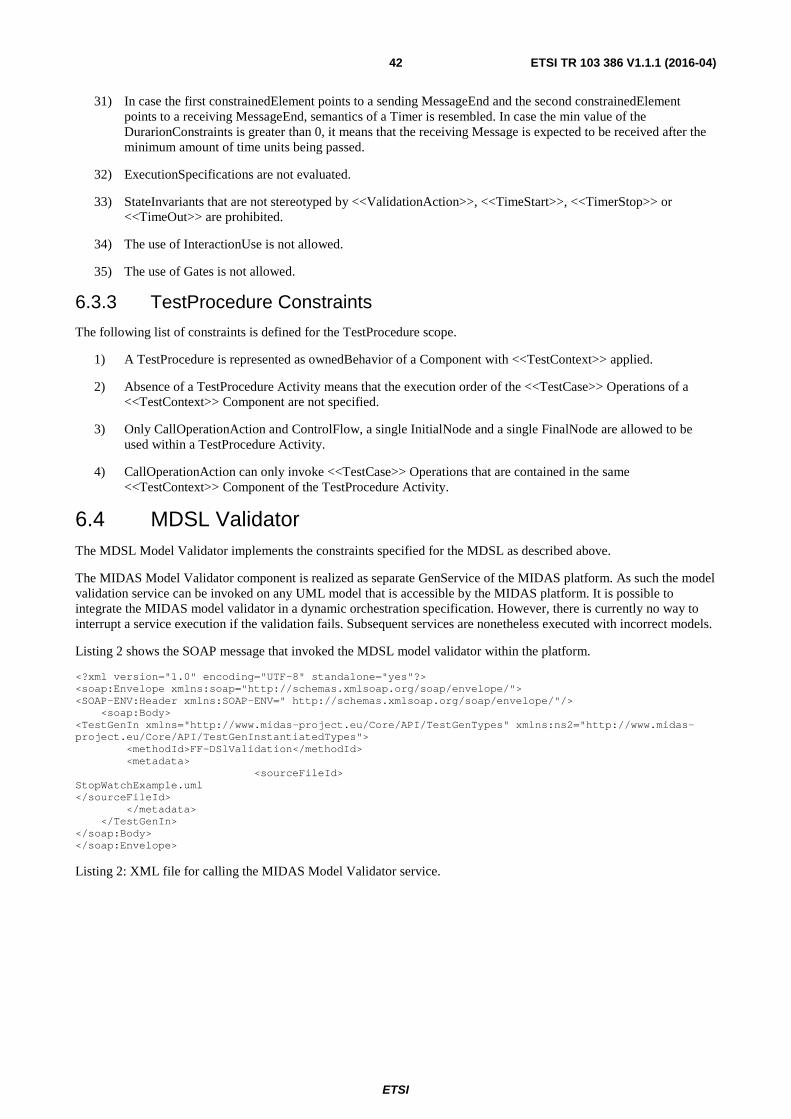
ETSI
ETSI TR 103 386 V1.1.1 (2016-04) 42
31) In case the first constrainedElement points to a sending MessageEnd and the second constrainedElement points to a receiving MessageEnd, semantics of a Timer is resembled. In case the min value of the DurarionConstraints is greater than 0, it means that the receiving Message is expected to be received after the minimum amount of time units being passed.
32) ExecutionSpecifications are not evaluated.
33) StateInvariants that are not stereotyped by <<ValidationAction>>, <<TimeStart>>, <<TimerStop>> or <<TimeOut>> are prohibited.
34) The use of InteractionUse is not allowed.
35) The use of Gates is not allowed.
6.3.3 TestProcedure Constraints
The following list of constraints is defined for the TestProcedure scope.
1) A TestProcedure is represented as ownedBehavior of a Component with <<TestContext>> applied.
2) Absence of a TestProcedure Activity means that the execution order of the <<TestCase>> Operations of a <<TestContext>> Component are not specified.
3) Only CallOperationAction and ControlFlow, a single InitialNode and a single FinalNode are allowed to be used within a TestProcedure Activity.
4) CallOperationAction can only invoke <<TestCase>> Operations that are contained in the same <<TestContext>> Component of the TestProcedure Activity.
6.4 MDSL Validator The MDSL Model Validator implements the constraints specified for the MDSL as described above.
The MIDAS Model Validator component is realized as separate GenService of the MIDAS platform. As such the model validation service can be invoked on any UML model that is accessible by the MIDAS platform. It is possible to integrate the MIDAS model validator in a dynamic orchestration specification. However, there is currently no way to interrupt a service execution if the validation fails. Subsequent services are nonetheless executed with incorrect models.
Listing 2 shows the SOAP message that invoked the MDSL model validator within the platform.
<?xml version="1.0" encoding="UTF-8" standalone="yes"?> <soap:Envelope xmlns:soap="http://schemas.xmlsoap.org/soap/envelope/"> <SOAP-ENV:Header xmlns:SOAP-ENV=" http://schemas.xmlsoap.org/soap/envelope/"/> <soap:Body> <TestGenIn xmlns="http://www.midas-project.eu/Core/API/TestGenTypes" xmlns:ns2="http://www.midas-project.eu/Core/API/TestGenInstantiatedTypes"> <methodId>FF-DSlValidation</methodId> <metadata> <sourceFileId> StopWatchExample.uml </sourceFileId> </metadata> </TestGenIn> </soap:Body> </soap:Envelope>
Listing 2: XML file for calling the MIDAS Model Validator service.

ETSI
ETSI TR 103 386 V1.1.1 (2016-04) 43
6.5 TTCN-3 Generator The TTCN-3 generator generates executable TTCN-3 scripts from any MDSL. The mapping of the two concepts are subsequently summarized.
Table 1: MDSL to TTCN-3 mapping
MDSL Concept TTCN-3 Concept TestContext Module TestContext's Property Module Parameters, Constants TestComponent Component (assuming the role of a tester in a test
configuration) SUT Component (assuming the role of the System
Interface component in TTCN-3) TestCase Operation Test Case TestConfiguration Test Configuration TestCase Operation Parameter Test Case Parameter Test Case Method Functions that runs on Components assuming the
role of a Test Component Primitive Type Basic Type and facets thereof Data Type record Enumeration Enumerated Signal record InstanceSpecification template LiteralSpecification Primitive Type Literal InstanceValue Reference to template DataPartition - Interface Component Port Type Port Component Port Connector Map/Connect Interval Range/Length SetExpression List of templates Property Field (of a record) Test Configuration Part Instance of a Component in a Test Configuration Message Asynchronous Signal Non-blocking send-/receive-Message Message SynchCall call/getcall-Aufruf Message Reply Reply-/getreply-Aufuruf Message AsyncCall Non-Blocking call DetermAlt Altstep Loop do … while, for, while … do Optional CombinedFragment If () then Alternative CombinedFragment If .. else if … else DurationConstraint timer start (duration), timer stop, timer timeout InteractionUse Function call
The TTCN-3 test case generator service takes as input a MIDAS DSL compliant model, which is created by a test engineer. The output of the generator is executable ttcn-3 test code, which can be executed on the Workbench. At this version all test cases that are specified in the model will be used by the ttcn-3 test case generator. Listing 1 shows a complete XML for execution of the ttcn-3 test case generator by using a MIDAS DSL compliant model.
<?xml version="1.0" encoding="UTF-8" standalone="yes"?> <soap:Envelope xmlns:soap="http://schemas.xmlsoap.org/soap/envelope/"> <SOAP-ENV:Header xmlns:SOAP-ENV="http://schemas.xmlsoap.org/soap/envelope/"/> <soap:Body> <TestGenIn xmlns="http://www.midas-project.eu/Core/API/TestGenTypes" xmlns:ns2="http://www.midas-project.eu/Core/API/TestGenInstantiatedTypes"> <taskId>TTCN-3Generation</taskId> <methodId>TTCN-3Generation</methodId> <metadata>

ETSI
ETSI TR 103 386 V1.1.1 (2016-04) 44
<sourceFileId> StopWatchExample.uml</sourceFileId> </metadata> </TestGenIn> </soap:Body> </soap:Envelope>
6.6 SCA4SAUT approach to system modelling
6.6.0 Introduction
The Service Component Architecture for Services Architecture Under Test (SCA4SAUT) is an alternative XML-based notation for the SAUT Construction model used as modelling language within MIDAS. The SAUT Construction model represents in a unified manner the structural model of the SAUT and the configuration model of the test system.
The SAUT Construction model supplies core information such as:
• the topology of the services architecture under test and its environment (see below) as a directed graph of nodes linked by service dependencies;
• the pointers to the service interface models, i.e. the WSDL/XSD files that define the service interfaces involved in the service dependencies between the nodes.
As a structural model of the services architecture under test, the SAUT Construction model is a concise representation of its topology as a directed graph of nodes (component(s)) that expose and declare respectively provided interfaces (service(s)) and required interfaces (reference(s)). The component(s) are connected by directed links (wire(s)) from reference(s) to service(s) that represent service dependencies. As a SAUT structural model, the Construction model is a descriptive model.
As a configuration model of the test system, the SAUT Construction model represents not only the SAUT actual component(s) and actual wire(s) (the SAUT composition) that are deployed as the system under test and are the targets of the test system, but also the SAUT virtual component(s) and virtual wires (the SAUT environment) that act as issuers and recipients of interactions to and from the SAUT actual component(s) and are implemented by the test system.
The SAUT Construction model allows binding the reference(s) and service(s) with their interface models (e.g. portTypes and ports defined in WSDL 1.1 documents [i.22]). The functional and behavioural models of the SAUT represented by protocol state machines that define external behaviours of components and service interaction protocols between components and business rules (pre/post conditions, data-flow requirements) on their interaction. These functional and behavioural models need to refer to the SAUT Construction model to be taken into account by the test generation procedures and the test system.
The SCA4SAUT notation is a restriction of the SCA V1.1 Assembly Model language [i.19] and a SCA4SAUT model is a standard SCA V1.1 Assembly Model.
The SAUT Construction (SCA4SAUT) model is a machine readable model, i.e. a representation that can be taken as a direct input by several MIDAS test components such as:
• The functional test case/oracle high level generator - it produces a Test Scenario Definition (TSD) model and one or more Test Suites (TSs). The TSD/TSs are generated from the SAUT Construction (SCA4SAUT) model, the service interface models (WSDL/XSD and the SAUT component(s) Protocol State Machine (4PSM) models [i.26]), through a sequence of transformation/generation steps.
• The dynamic test scheduler takes the SAUT Construction (SCA4SAUT) model, a related Test Scenario Definition (TSD) model and one Test Suite (TS) data set as inputs in order to build the internal model for the probabilistic inference engine that drives the dynamic scheduling of the test execution.
• The functional test execution environment generator takes as inputs the SAUT Construction (SCA4SAUT) model, the Test Scenario Definition (TSD) model and the Test Suite (TS) data set and produces the TTCN 3 library that implements the executable test system.

ETSI
ETSI TR 103 386 V1.1.1 (2016-04) 45
The SCA4SAUT modelling language represent a novel approach to model test system models. Its applicability to MBT methodology needs further proof-of-concept experimentation that goes beyond the scope of MIDAS project. To date of the present document, the opinion was shared, that the modelling investigate new, straight forward approach where the test models are generated from widely used XML/XSD descriptions. In addition, it takes multiple consideration into account, e.g. service topology, functional and behavioural models, and references and interfaces to the SAUT external environment test stimulus and responses.
6.6.1 Overview of the SCA4SAUT model
The SCA4SAUT model is a structural model of the services architecture under test.
The SCA4SAUT model depicts the structure of the services architecture under test through a directed graph whose nodes are components and whose directed links are wires that connect required interfaces to provided interfaces.
In the SCA4SUT approach, the structure of a SAUT component, that is the required interfaces it declares and the provided interfaces it exposes, is documented by specifying its implementation, i.e. a Participant. The designed Participant describes the structure of the component.
The concept of Participant is taken from the SoaML specification [i.20]: "A participant is the type of a provider and/or consumer of services. In the business domain a participant can be a person, organization, or system. In the systems domain a participant can be a system, application, or component". SCA4SAUT refines the definition in a way that Participant documents the implementation of a SAUT component as an aggregation of provided and required interfaces.
Participants can be Atomic or Compound:
• the Atomic Participant is the basic building block of the SCA4SAUT model; it represents an aggregation of provided and required interfaces whose structure cannot be decomposed further in several interacting sub-components - in the Atomic Participant, the provided and required interfaces are bound with interface definitions included in standard documents;
• the Compound Participant represents an aggregation of interacting components that are implemented by Atomic and Compound Participants - the provided and required interfaces of each component of a Compound Participant can be either wired with the compatible ones of the other components, representing a service composition, or "promoted" as interfaces of the Compound Participant as a whole.
The SAUT components' provided and required interfaces are fully specified by their Participant implementations. In the SCA Assembly Model terminology, a provided interface is called a service and a required interface is called a reference. Each Atomic Participants document specifies the bindings of its services and references with service interface definitions, for instance portType(s) and port(s) defined in a WSDL 1.1 document [i.22].
To specify the actual service dependencies between SAUT (and Compound Participant) components, the SCA4SAUT model utilizes the SCA Assembly Model concept of wire. A wire represents a directed link between a component reference (the wire source) and a component service (the wire target). The meaning is that the reference and service are actually connected in the services architecture and are able to convey interactions between them. The wire source and target need to belong to different components - loops are not allowed in the component/wire directed graph - and need to be compatible, i.e. bound with the same service interface definition.
In summary, a SAUT model specifies components that are connected by wires. A SAUT model represents a closed system: it neither exposes services nor declares references as a whole. In a SAUT, each component plays either an Actual role or a Virtual role.
The SAUT Actual components are used to represent systems that are aggregations of physically deployed, localized service and reference endpoints. These service and reference endpoints are the observation and stimulation points of the service testing activity, i.e. the locations where the behaviour of the deployed SAUT components can be stimulated and observed.
Conversely, the Virtual components are used to model virtualized systems that carry out the stimulation and the observation of the Actual components' behaviours at their interfaces. They need to be implemented by test system components. Hence, when it is said that a Virtual component is implemented by a Participant, this means that the implementation Participant supplies only the abstract specification of the services and references that the component may respectively expose and declare at its level, but the concrete endpoints of these services and references, if any, are not taken into account because these services and references are implemented by the test system.

ETSI
ETSI TR 103 386 V1.1.1 (2016-04) 46
6.6.2 Introduction to the SCA Assembly notation
The Service Component Architecture for Services Architecture Under Test (SCA4SAUT) notation is a restriction of the SCA V1.0 Assembly Model language [i.18]. Hence, the SCA4SAUT model is a standard SCA V1.0 Assembly Model.
Service Component Architecture (SCA) is a set of specifications that describe how to build applications and systems as services architectures. SCA extends and complements prior approaches to implementing services, and it is built on open standards. Thus, it is a standard specification for building and deploying services architectures whose participant systems are implemented in different technologies. The services architecture configuration and implementation are specified through a SCA Assembly Model, i.e. a set of valid XML documents that describe:
• the systems' implementations, through links with the executable software components, built in different technologies;
• the service interfaces that these systems provide and require, through links to standard interface descriptions such as WSDL 1.1 documents [i.22];
• the service provide/consume actual links between these systems, as wires between required and provided interfaces;
• user-defined properties of participants, participants' implementations, required and provided interfaces.
An important characteristic of the SCA V1.0 Assembly Model is that it is machine readable and allows the effective configuration of a services architecture by a SCA run time framework such as Apache Tuscany, that are in charge of building the run time binding between all the aforementioned elements (participant systems, service contracts, wires, etc.). Other tools are available (e.g. the SCA tools plug-in provided with open-source Eclipse Kepler) that allow graphical design and validation of a SCA Assembly Model. The availability of the aforementioned tools allows automated checking of several properties of the SCA4SAUT model as a standard SCA 1.0 Assembly Model.
The main goal of the SCA Assembly Model and the related frameworks is to automate the deployment of services architectures and the mutual binding of the service architecture components. The resulting "augmented" SCA4SAUT model can be used as a standard SCA Assembly Model by at least one of the aforementioned SCA run time frameworks (the reference implementation), as a prescriptive model that drives the deployment of the service architecture under test and the binding of its components.
The SCA V1.0 Assembly Model is recorded through a collection of XML documents whose root element - for each of them - is a composite. A SCA composite is used to assemble SCA elements in logical groupings and can include:
(i) the description of a set of components with their references and services;
(ii) the description of a set of wires that connect components' references to services;
(iii) the description of a set of references and services that "promote" components' services and references, which are respectively exposed and declared by the composite as a whole.
All the SCA4SAUT modelling main elements, i.e. Atomic Participant, Compound Participant and SAUT, are represented as composites.
The terms 'document', 'element', 'attribute', 'document element', 'child element', 'children' employed in the present document refer to information items of the SCA4SAUT XML documents [i.23].
The adopted convention is that the SCA4SAUT traits and the pseudo-schemas of the SCA4SAUT elements are given through XML snippets where attribute values and texts (in italics) name the data types. Characters are appended to elements and attributes in order to specify the element/attribute value multiplicity as follows:
• nothing means multiplicity 1;
• '?' means multiplicity 0 or 1;
• '*' means multiplicity between 0 and unbound upper limit;
• '+' means multiplicity between 1 and unbound upper limit;
• '[n..m]' means multiplicity defined by a non-negative integer interval (n and m are integer variables);

ETSI
ETSI TR 103 386 V1.1.1 (2016-04) 47
• '[n..*]' means multiplicity between n and an unbound upper limit.
The string '…' inserted inside a tag (such as '<element … />' or '<element … >') or in the element content such as '<element> … </element>') indicates that elements, attributes and element contents that are not relevant within the context are being omitted.
The XML namespace prefixes defined in Table 1 are used to designate the namespace of the element being defined.
Table 2: SCA4SAUT namespaces and namespace prefixes
prefix namespace URI definition wsdl http://schemas.xmlsoap.org/wsdl/ WSDL namespace for WSDL framework.
wsdli http://www.w3.org/ns/wsdl-instance WSDL Instance Namespace soap http://schemas.xmlsoap.org/wsdl/soap/ WSDL namespace for WSDL SOAP binding. soap12 http://schemas.xmlsoap.org/wsdl/soap12/ WSDL namespace for WSDL SOAP 1.2 binding. http http://schemas.xmlsoap.org/wsdl/http/ WSDL namespace for WSDL HTTP GET &
POST binding. mime http://schemas.xmlsoap.org/wsdl/mime/ WSDL namespace for WSDL MIME binding. soapenc http://schemas.xmlsoap.org/soap/encoding/ Encoding namespace as defined by SOAP
1.1 [i.21]. soapenv http://schemas.xmlsoap.org/soap/envelope/ Envelope namespace as defined by SOAP
1.1 [i.21]. xsi http://www.w3.org/2000/10/XMLSchema-instance Instance namespace as defined by XSD [i.25]. xs http://www.w3.org/2000/10/XMLSchema Schema namespace as defined by XSD [i.25]. sca http://www.osoa.org/xmlns/sca/1.0 Schema namespace as defined by [i.18]. tns (various) The "this namespace" (tns) prefix is used as a
convention to refer to the present document.
Snippets starting with <?xml contain information that is sufficient to conform to the present document; others snippets are fragments and require additional information to be specified in order to conform.
The XPath 2.0 standard language [i.24] is utilised to localise and designate elements and attributes of the pseudo-schemas.
The pseudo-schema of a "generic" SCA composite is presented in the snippet below:
<?xml version="1.0" encoding="UTF-8"?> <sca:composite xmlns:sca="http://www.osoa.org/xmlns/sca/1.0" xmlns = … … name="xs:NCName" targetNamespace="xs:anyURI"> <sca:component name="xs:NCName">+ <sca:implementation … />? <sca:service … />* <sca:reference … />* <sca:property … />* </sca:component> <sca:service … />* <sca:reference … />* <sca:wire … />* <sca:property … />* </sca:composite>
The composite element has the attributes:
• name : xs:NCName (required) - the name of the composite;
• targetNamespace : xs:anyURI (required) - an identifier for the namespace into which the names of the composite element and its descendants are specified.

ETSI
ETSI TR 103 386 V1.1.1 (2016-04) 48
The composite element has the child elements:
• component (0..n) - The composite element has zero or more child components. Components are configured instances of implementations. A component element carries out data about its implementation and its realised provided interfaces (services) and used required interfaces (references). The component element has the attribute:
- name : xs:NCName (required) - the name of the component.
- The component element has the child elements:
- implementation (0..1) - The component element has at most one implementation child element, which describes the implementation used by the component. The implementation element is an abstract element that needs to be instantiated by type specific implementation elements, such as: implementation.java, implementation.bpel, implementation.cpp, and implementation.c that refer respectively to Java, BPEL, C++, and C implementation types. implementation.composite points make use of a SCA composite as an implementation.
- service (0..n) - The component element can have zero or more service child elements that are utilised to specify the provided interfaces that are exposed by the component.
- reference (0..n) - The component element can have zero or more reference child elements that are utilised to specify the required interfaces that are declared by the component.
- property (0..n) - The component element can have zero or more property child elements that are utilised to configure parameters of the implementation or to provide information about the implementation.
• service (0..n) - each service child element of a composite describes a provided interface exposed by the composite and is defined by promoting a service defined by one of the components of the composite. There can be zero or more service elements in a composite.
• reference (0..n) - each reference child element of a composite represents a required interface declared by the composite and is defined by promoting a reference defined by one of the components of the composite. There can be zero or more reference elements in a composite.
• wire (0..n) - each wire child element of a composite connects a component reference (source) to a component service (target) of the composite. There are zero or more wire elements as children of a composite. The source component of a wire needs to be different from the target component (no graph loops are allowed). The source reference and the target service need to be compatible.
• property (0..n) - properties allow for the configuration of an implementation with external data values. A composite can declare zero or more properties. Each property has a type, which is either simple or complex. An implementation can also define a default value for a property.
The specification of a composite needs to be contained in a document that needs to be stored in a standalone file whose relative name needs to be '$cpst.composite', where $cpst is the value of the /composite/@name attribute and this value is suffixed by the string '.composite'.
The SCA composite element is used within SCA4SAUT to represent all the main elements of the SCA4SAUT model, i.e.:
• Atomic Participants
• Compound Participants
• SAUTs
The pseudo-schemas of the SCA4SAUT composite elements corresponding to the model elements listed above (Atomic and Compound Participants, SAUTs) are presented in the appropriate sections of the present document, where the SCA4SAUT specific restrictions on the SCA V1.0 Assembly Model for each SCA4SAUT modelling element type are also detailed.

ETSI
ETSI TR 103 386 V1.1.1 (2016-04) 49
An Atomic Participant is an aggregation of references and services respectively declared and exposed by only one (unique) /composite/component. The unique Atomic Participant composite/component defines directly the structure of these references and services by binding them to their interfaces definitions (e.g. portType/ports defined in WSDL documents).
A Compound Participant composite represents an aggregation of components that are implemented by Atomic and Compound Participants. The internal structure showing the service links between these components is represented by means of wire child elements. Some services and references respectively exposed and declared by some components of the Participant composite are "promoted", which means that they become respectively services and references of the Compound Participant composite as a whole.
A SAUT is a SCA composite that represents the structure of the services architecture under test. The SAUT composite has a specific component structure:
• At least one (for unit test) or more (for integration test) Actual components. Each Actual component needs to be implemented by an Atomic or Compound Participant composite. Any Participant composite that exposes at least one service MAY implement an Actual component.
• At least one (or more) Virtual components. Each Virtual component needs to be implemented by an Atomic or Compound Participant composite. At least, any Virtual component needs to either declare one reference that be wired with an Actual component service or expose one service that needs to be wired with an Actual component reference. At least, one service exposed by a SAUT Actual component needs to be wired to a reference declared by a SAUT Virtual component.
• The SAUT composite structure needs to be a connected directed graph of components (nodes) linked by wires (links). The SAUT connected directed graph is not allowed to contain any loop, i.e. any link that is incident to and from the same node.
A complete SCA4SAUT specification is provided in [i.26]. Examples of the use of SCA4SAUT modelling approach are provided in clauses A.2 and A.3.
7 Deployment of the TPaaS on the public cloud infrastructure
7.0 Development and production frameworks Within the MIDAS project, the TPaaS has been designed, architected, and implemented according to a SOA-based paradigm, and provided as an integrated Testing as a Service framework available on demand, i.e. on a self-provisioning, pay-per-use, elastic basis.
More specifically, to allow the test method developer partners (is short TMD Partner) to integrate their methods in the developed TPaaS platform, they have been provided with a seamless, loosely coupled development and integration platform adopting a virtualization approach. The TMD partners have been equipped with an environment relying on open-source and stable virtualization technologies to deploy all the TPaaS components in a consolidated virtual machine. The selected tools used to set up the virtual machine allow their users to create and configure lightweight, reproducible, and portable virtual machine environments. The Virtual Box plays the role of the virtual machine hypervisor. This virtual machine includes standard hardware architecture, operating system, developer tools, application containers, web servers, and libraries shared among all partners as a Virtual Machine Image (VMI). The VM software tools are also used to deploy the TPaaS platform on the Cloud infrastructure with all the added components integrated in it (e.g. the TPaaS Production Environment). In such an environment, all TPaaS components, together with a basic TPaaS user front-end, are deployed on the Cloud by exploiting all the Cloud building blocks , such as Cloud Computing resources, Auto Scaling, Storage, Elastic Load Balancing, and so on.
NOTE: The selected tools used to set up the virtual machine are Vagrant and Ansible.
7.1 Integration of test methods on the TPaaS platform
7.1.0 Introduction
To allow the TMD Partners to integrate their methods in the TPaaS platform, they have been provided with a seamless, loosely coupled development and integration platform adopting a virtualization approach.

ETSI
ETSI TR 103 386 V1.1.1 (2016-04) 50
The integration platform supports developer partners in their implementation, debugging and testing activities.
More specifically, the TMD Partners are equipped with a TPaaS Development Environment (in short, devenv_vm). The Development Environment is deployed on a local machine by each developer partner, so allowing to locally provide the basic TPaaS platform by emulating the main building blocks that are available on the TPaaS platform deployed on the Cloud. TPaaS DevE allows TMD Partners the following twofold benefits:
a) to avoid using Cloud resources in the TPaaS development phase, so allowing for a cost-effective strategy to develop and deploy the TPaaS platform on the Cloud without wasting Cloud resources;
b) to guarantee the interoperability of the independently developed components since they are released only once they are stable and run on the same shared development environment aligned among TMD Partners.
The VM software tools are also used to deploy the TPaaS platform in the Cloud infrastructure with all the added components integrated in it. The TPaaS platform was deployed in the Cloud as the Production Environment (in short, prodenv_vm).
In order to allow a complete and easy integration of the software modules into the integrated TPaaS prototype, all the partners develop each module by implementing the correspondent service interface (WSDL) and providing a single Java .war file that includes all the necessary resources (configuration, properties and XML files) and dependencies (.jar and resource files) inside the .war file. In such a way, the Tomcat7 service container can deploy specific class loaders (one per .war) to resolve all dependencies without any external configuration setup.
Beside end user services, which have been described in clause 4.1.1, additional tenancy administration functionalities are offered by two tenancy admin services:
• Identity & Authentication Service: the service implementation exposes APIs to manage the end users of a single tenancy. The tenancy admins will have access to secure mechanisms to register, inspect and delete tenancy end users. Registered tenancy end users will be able to access all tenancy services and test methods with transparent secure mechanisms. This service is one of the crosscutting services of the TPaaS platform since it is used by all TPaaS services requiring authentication of end users before they perform any operation. The implemented APIs are used to store structured information (database table), and are built on top of the MySQL Relational Data Base Management System (RDBMS) engine.
• Accounting & Billing Service: this API allows reporting the Cloud resources consumption and usage of a single tenancy. The tenancy admins will have access to secure mechanisms to inspect the usage and costs of the tenancy Cloud resources, upgraded regularly according to the Cloud provider accounting and billing policies.
7.1.1 The Database structure for the MIDAS TPaaS
Each tenancy has its own database containing all the tables that are used for the implementation of the Tenancy Admin Services and the End User Services. The database name is the same as the tenancy name. The tables created within the database are:
• user: the table stores the information about the end users belonging to a tenancy. The Identity & Authentication Service provides APIs allowing the tenancy admin to create and delete tenancy end users, as well as to list current members of a tenancy, and to verify that each member of a tenancy is authenticated before invoking the facilities of that tenancy. The table is depicted in Figure 23. The username and password fields are the ones used for the login access to the TPaaS Portal or to authenticate end users before invoking the facilities of that tenancy. The password field is stored by using the BCrypt java library that implements OpenBSD-style Blowfish password hashing.

ETSI
ETSI TR 103 386 V1.1.1 (2016-04) 51
Figure 23: The user table
• test_method and test_method_endpoints: they are the tables implemented for the Test Method Query Service. In such tables, the information about the available test methods is stored. The test_method table contains the unique identifiers of the symbolic names of the test methods, the test_method_endpoints table instead stores the information, for each unique symbolic name, about the type of the test component (endpoint_type), and the respective endpoint url (endpoint_url) of the web service implementation. The test components are the service implementations of the WSDL interface related to the Core Services. The database tables are shown in Figure 24.
Figure 24: The test_method and test_method_endpoints tables
• test_task_status: the table represents the structured information for the Test Status Service, a service that keeps trace of the user testing activities carried out within a tenancy. Each test task launched by a user of the tenancy will have a unique identifier and the service keeps trace of the user that launched the test task, the status of the task (running, completed, failed) and the invocation time and completion time. In Figure 25 the structure of the test_task_status table is shown.
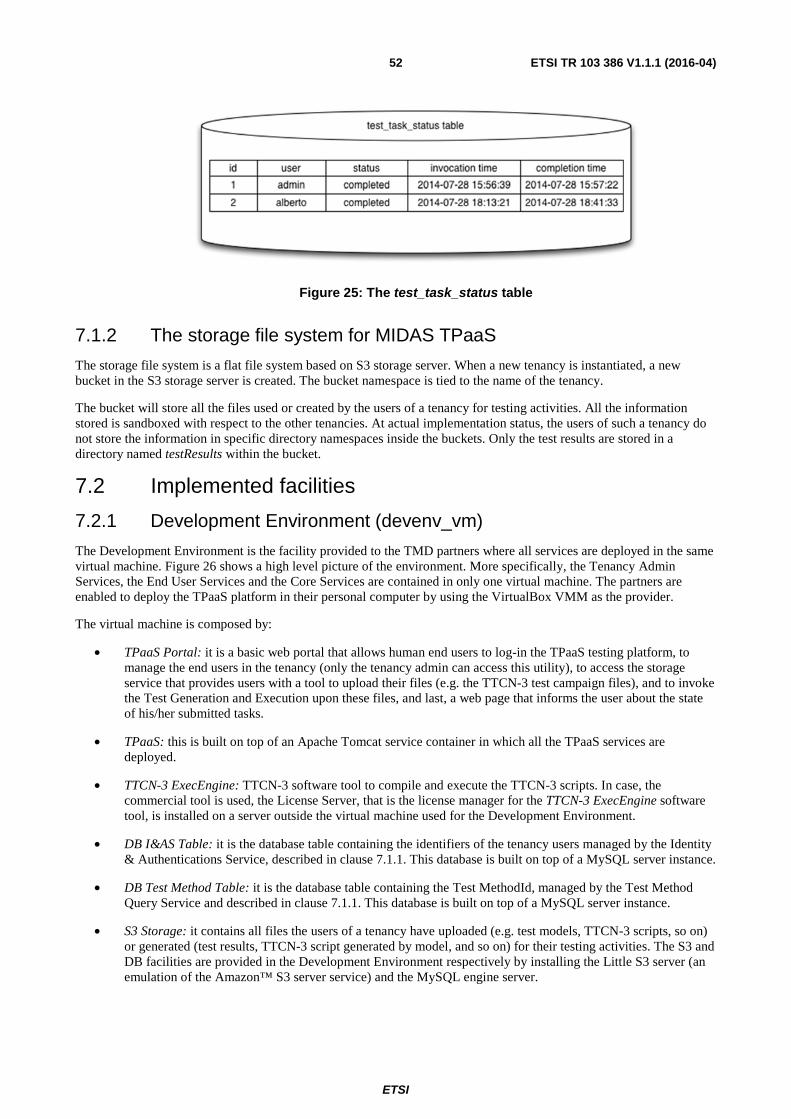
ETSI
ETSI TR 103 386 V1.1.1 (2016-04) 52
Figure 25: The test_task_status table
7.1.2 The storage file system for MIDAS TPaaS
The storage file system is a flat file system based on S3 storage server. When a new tenancy is instantiated, a new bucket in the S3 storage server is created. The bucket namespace is tied to the name of the tenancy.
The bucket will store all the files used or created by the users of a tenancy for testing activities. All the information stored is sandboxed with respect to the other tenancies. At actual implementation status, the users of such a tenancy do not store the information in specific directory namespaces inside the buckets. Only the test results are stored in a directory named testResults within the bucket.
7.2 Implemented facilities
7.2.1 Development Environment (devenv_vm)
The Development Environment is the facility provided to the TMD partners where all services are deployed in the same virtual machine. Figure 26 shows a high level picture of the environment. More specifically, the Tenancy Admin Services, the End User Services and the Core Services are contained in only one virtual machine. The partners are enabled to deploy the TPaaS platform in their personal computer by using the VirtualBox VMM as the provider.
The virtual machine is composed by:
• TPaaS Portal: it is a basic web portal that allows human end users to log-in the TPaaS testing platform, to manage the end users in the tenancy (only the tenancy admin can access this utility), to access the storage service that provides users with a tool to upload their files (e.g. the TTCN-3 test campaign files), and to invoke the Test Generation and Execution upon these files, and last, a web page that informs the user about the state of his/her submitted tasks.
• TPaaS: this is built on top of an Apache Tomcat service container in which all the TPaaS services are deployed.
• TTCN-3 ExecEngine: TTCN-3 software tool to compile and execute the TTCN-3 scripts. In case, the commercial tool is used, the License Server, that is the license manager for the TTCN-3 ExecEngine software tool, is installed on a server outside the virtual machine used for the Development Environment.
• DB I&AS Table: it is the database table containing the identifiers of the tenancy users managed by the Identity & Authentications Service, described in clause 7.1.1. This database is built on top of a MySQL server instance.
• DB Test Method Table: it is the database table containing the Test MethodId, managed by the Test Method Query Service and described in clause 7.1.1. This database is built on top of a MySQL server instance.
• S3 Storage: it contains all files the users of a tenancy have uploaded (e.g. test models, TTCN-3 scripts, so on) or generated (test results, TTCN-3 script generated by model, and so on) for their testing activities. The S3 and DB facilities are provided in the Development Environment respectively by installing the Little S3 server (an emulation of the Amazon™ S3 server service) and the MySQL engine server.

ETSI
ETSI TR 103 386 V1.1.1 (2016-04) 53
Figure 26: The Development Environment
The System Under Test, that represents the target of the testing activity, resides outside the Development Environment.
In the Development Environment, Auto Scaling and Elastic Load Balancing facilities offered by the Cloud environment are not available and not simulated, since they are not required to test the TPaaS components during their development. Furthermore, the VM local computing resources are limited, while in the Cloud both the number of VMs to be used and the appropriate dimension of the computing resources are selected.
To provide the partners with an easy way to update the test components developed and make them available on the MIDAS Portal as test methods, an sql script (testmethod.sql) is used. This script file enables the developer partners to update the tables of the Test Method Query Service in independent and autonomous way when they develop their test components.
7.2.2 Production Environment (prodenv_multivm)
The adopted strategy is one of the possible deployment strategies can be used for the deployment of the MIDAS platform on the Cloud, as described in [i.3].
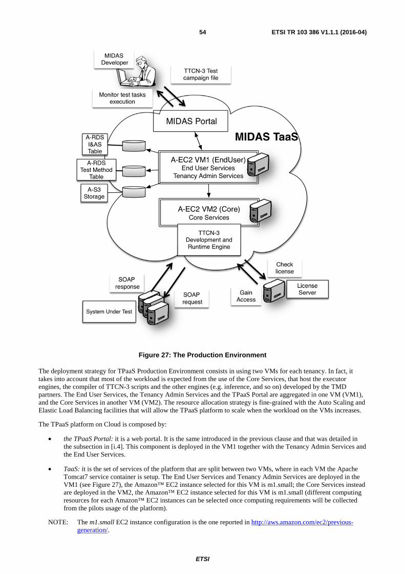
ETSI
ETSI TR 103 386 V1.1.1 (2016-04) 54
Figure 27: The Production Environment
The deployment strategy for TPaaS Production Environment consists in using two VMs for each tenancy. In fact, it takes into account that most of the workload is expected from the use of the Core Services, that host the executor engines, the compiler of TTCN-3 scripts and the other engines (e.g. inference, and so on) developed by the TMD partners. The End User Services, the Tenancy Admin Services and the TPaaS Portal are aggregated in one VM (VM1), and the Core Services in another VM (VM2). The resource allocation strategy is fine-grained with the Auto Scaling and Elastic Load Balancing facilities that will allow the TPaaS platform to scale when the workload on the VMs increases.
The TPaaS platform on Cloud is composed by:
• the TPaaS Portal: it is a web portal. It is the same introduced in the previous clause and that was detailed in the subsection in [i.4]. This component is deployed in the VM1 together with the Tenancy Admin Services and the End User Services.
• TaaS: it is the set of services of the platform that are split between two VMs, where in each VM the Apache Tomcat7 service container is setup. The End User Services and Tenancy Admin Services are deployed in the VM1 (see Figure 27), the Amazon™ EC2 instance selected for this VM is m1.small; the Core Services instead are deployed in the VM2, the Amazon™ EC2 instance selected for this VM is m1.small (different computing resources for each Amazon™ EC2 instances can be selected once computing requirements will be collected from the pilots usage of the platform).
NOTE: The m1.small EC2 instance configuration is the one reported in http://aws.amazon.com/ec2/previous-generation/.

ETSI
ETSI TR 103 386 V1.1.1 (2016-04) 55
• TTCN-3 ExecutionEngine: TTCN-3 software tool to execute the TTCN-3 scripts.
• DB I&AS Table: it is the database table containing the identifiers of the tenancy users managed by the Identity & Authentications Service. This functionality uses the Public Cloud provider RDS for MySQL as structured storage service.
• DB Test Method Table: it is the database table containing the Test Method Ids, managed by the Test Method Query Service. This functionality uses the Public Cloud provider RDS for MySQL as structured storage service.
• S3 Storage: it contains all files the users of a tenancy have uploaded (e.g. test models, TTCN-3 scripts, so on) or generated (test results, TTCN-3 script generated by model, and so on); the content is stored in Public Cloud provider S3.
When the MIDAS platform is deployed on the Cloud, the storage needs for S3 and DB facilities are provided by the Amazon™ Web Services, respectively the Public Cloud provider S3 and Public Cloud provider RDS. This allows relying on Public Cloud provider AWS that makes it easy to set up, operate, and scale a relational database and persistent storages in the Cloud. It provides cost-efficient and resizable capacity while managing time-consuming database administration tasks and storage backups/replications.
The License Server is the license manager for the TTCN-3 Execution engine software tool that is installed on a server outside the Cloud.
In the Production Environment the TPaaS platform is exploiting Auto Scaling and Elastic Load Balancing facilities offered by the underlying Cloud infrastructure. Furthermore, the VMs computing resources can be resized to fit the CPUs, RAM, network I/O requirements of the TPaaS components.

ETSI
ETSI TR 103 386 V1.1.1 (2016-04) 56
Annex A: End User Use Case Examples
A.1 Direct Execution Use Case Example: IMS Conformance testing
A.1.0 Overview In this clause, a demonstration with the Direct Execution use case is presented and, how the MIDAS platform can be used for already existing TTCN-3 test suites. As a starting point, the TTCN-3 test suite was used, that can be found under multi-part test standard ETSI TS 102 790-1 [i.13], ETSI TS 102 790-2 [i.14] and ETSI TS 102 790-3 [i.15] covering the IP Multimedia core network Subsystem (IMS) equipment supporting the Internet Protocol (IP) multimedia call control protocol based on Session Initiation Protocol (SIP) and Session Description Protocol (SDP) Conformance Testing.
The objective of this use case is to evaluate the suitability of the Cloud based testing environment in comparison with the stand-alone commercial TTCN-3 test development and execution tool, which is currently used for conformance testing with the standardized TTCN-3 test suites. For sake of comparison, a standalone TTCN-3 tool was used. The execution engine of the commercial TTCN-3 tool is also integrated into MIDAS TPaaS. Suitability was evaluated from the following perspectives:
• Completeness of the TPaaS Framework, e.g. whether the current TPaaS implementation offer the adequate and complete functionality in order to perform all testing tasks required to execute test cases, make verdicts for each test case and produce test reports.
• Support for efficient regression testing, e.g. does TPaaS efficiently support regression tests, which can either be result of changes in the TTCN-3 test suite or in SUT. The efficiency was measured by the complexity of tasks required by the testing engineer within the TPaaS environment and outside of the TPaaS in comparison with the tasks performed by the commercial TTCN-3 tool.
• Required TPaaS acquisition effort, e.g. measured by training effort required by the testing engineer with hands-on experience with commercial TTCN-3 tool to become comfortable with TPaaS environment for direct execution use-case in order to achieve target test objectives comparable with the commercial test tool.
A.1.1 IMS as SUT As the direct execution use case is independent from system modelling and test suite generation, e.g. it is assumed that TTCN-3 test suites already exist, it is intended that specific MIDAS TPaaS features that support SOA testing cannot have been utilized. Therefore, the non-SOA SUT was selected, for which the TTCN-3 test suites already exist. With this approach, the suitability of the MIDAS TPaaS for other technical domains was also tested.
IP Multimedia Subsystem (IMS) definitions are provided in ETSI TS 123 228 [i.16] which comprises all Core Network(CN) elements for provision of multimedia services. CN elements communicate over different reference points (e.g. Gm, Mw, Ic).

ETSI
ETSI TR 103 386 V1.1.1 (2016-04) 57
Figure A.1: Architecture of the IP Multimedia Core Network Subsystem with marked elements used as SUT
Figure A.1 represents the IMS reference architecture including interfaces towards legacy networks and other IP based multimedia systems. Components P-CSCF, I-CSCF, S-CSCF and IBCF are core IMS elements where the need for conformance testing arises. IMS core network functionality is accessible via SIP based interfaces and defined by ETSI TS 124 229 [i.17].
A.1.2 Test configuration
A.1.2.1 SUT architecture
Standard ETSI TS 124 229 [i.17] was used as a base standard for preparation of multi-part test standard ETSI TS 102 790-1 [i.13], ETSI TS 102 790-2 [i.14] and ETSI TS 102 790-3 [i.15] covering the IP Multimedia core network Subsystem (IMS) equipment supporting the Internet Protocol (IP) multimedia call control protocol based on Session Initiation Protocol (SIP) and Session Description Protocol (SDP) Conformance Testing.
Documents consist of the following parts:
• Part 1: "Protocol Implementation Conformance Statement (PICS)";
• Part 2: "Test Suite Structure (TSS) and Test Purposes (TP)";
• Part 3: "Abstract Test Suite (ATS) and partial Protocol Implementation eXtra Information for Testing (PIXIT) proforma specification".
Figure A.2 shows Test System (TS) components which were connected to the SUT IMS Core Network elements.

ETSI
ETSI TR 103 386 V1.1.1 (2016-04) 58
Figure A.2: Simplified architecture of IMS core elements - CSCFs - connected with other
For the MIDAS platform the original TTCN-3 test suite from ETSI TS 102 790-3 [i.15] was adopted and only few test cases were run against SUT to prove the direct execution concept. A reference point (Gm interface) between UE and P-CSCF was used to demonstrate basic call functionality (Figure A.3).
TS
IMS UE1
Gm1
SUT
Gm2 UE2
Figure A.3: Test configuration CF_2Gm
A.1.2.2 Message flow scenarios
The following call flow represents 3 different entities (UE1, UE2 and IMS CSCFs). TPaaS execution engine with already prepared test cases within test suite simulates the behaviour of one or more UEs entities communicating with the IMS core network under test. Messages between different entities present registration of UE1 and UE2, establishment of basic call between them and release of established call after media conversation. This is only one example of successful call between two UEs. A complex state machine within the IMS system provides communication between UE entities, e.g. to register, connect entities together and release them or make reaction in some other situations.
AS
IMSx
IMSy
UE
SUT
CSCFs
Mw
Ic
Isc
Gm
SIP protocol

ETSI
ETSI TR 103 386 V1.1.1 (2016-04) 59
Figure A.4: Registration, Basic call between two UEs and Call release
Test cases written within ETSI TS 102 790-2 [i.14] represent only preconditions, action done by the UE entities and required reaction due to the base standards which have to be tested and checked by the test system running under TPaaS. To follow the idea of conformance type of testing the normal behaviour of SUT can be achieved by running each test individually where TP represents the middle of the call. Other parts of call flow are hidden in preamble and postamble. For other types of testing (security, performance, fuzzing, etc.) the approach to making those tests needs to be different.
A.1.2.3 Test suite structure
The overall Test suite structure (TSS) is defined in ETSI TS 102 790-2 [i.14]. For a direct test execution example the following parts of existing TSS were used:
1) Test purposes for the Gm interface only:
i) Registration procedures;
ii) Initial dialog request procedures.
A.1.3 Direct execution procedures taken within TPaaS Due to the procedure described within the direct test execution has been executed according to sequence diagram described in 5.1.1 Direct test execution use case TaaS sequence diagram. All related steps were executed from the End User perspective. For usage of this platform, a simplified and reduced Executable Test Suite (ETS) was developed from the existing ATS test suite which was part of ETSI TS 102 790-3 [i.15]. This ETS was archived within IMS_sample.zip file, consisting of several files, that are listed in Table A.1.

ETSI
ETSI TR 103 386 V1.1.1 (2016-04) 60
Table A.1: ETS test suite used for direct test execution use case
Parts Description Files & folders ATS source code structure
ATS and libraries written in TTCN-3 core language
ATS_sample |-- ATS_sample/AtsIms_Gm_TCFunctions.ttcn |-- ATS_sample/AtsIms_Gm_Testcases.ttcn |-- ATS_sample/AtsIms_PICS.ttcn |-- ATS_sample/AtsIms_PIXITS.ttcn |-- ATS_sample/AtsIms_Templates.ttcn |-- ATS_sample/AtsIms_TestCases.ttcn |-- ATS_sample/AtsIms_TestConfiguration.ttcn `-- ATS_sample/AtsIms_TestSystem.ttcn LibCommon |-- LibCommon/LibCommon_AbstractData.ttcn |-- LibCommon/LibCommon_BasicTypesAndValues.ttcn |-- LibCommon/LibCommon_DataStrings.ttcn |-- LibCommon/LibCommon_Sync.ttcn |-- LibCommon/LibCommon_TextStrings.ttcn |-- LibCommon/LibCommon_Time.ttcn `-- LibCommon/LibCommon_VerdictControl.ttcn LibSip_woXSD |-- LibSip_woXSD/LibSip_Interface.ttcn |-- LibSip_woXSD/LibSip_PIXITS.ttcn |-- LibSip_woXSD/LibSip_SDPTypes.ttcn |-- LibSip_woXSD/LibSip_SIPTypesAndValues.ttcn |-- LibSip_woXSD/LibSip_Steps.ttcn |-- LibSip_woXSD/LibSip_Templates.ttcn |-- LibSip_woXSD/LibSip_XMLTypes.ttcn `-- LibSip_woXSD/XSDAUX.ttcn LibIms_wo_XSD |-- LibIms_wo_XSD/LibIms_Interface.ttcn |-- LibIms_wo_XSD/LibIms_PIXITS.ttcn |-- LibIms_wo_XSD/LibIms_SIPTypesAndValues.ttcn |-- LibIms_wo_XSD/LibIms_Steps.ttcn `-- LibIms_wo_XSD/LibIms_Templates.ttcn
Compiled ATS Compiled TTCN-3 ATS source code for execution
ttcn3build |-- ttcn3build/AtsIms_Gm_TCFunctions.jar |-- ttcn3build/AtsIms_Gm_Testcases.jar |-- ttcn3build/AtsIms_PICS.jar |-- ttcn3build/AtsIms_PIXITS.jar |-- ttcn3build/AtsIms_TestCases.jar |-- ttcn3build/AtsIms_TestConfiguration.jar |-- ttcn3build/AtsIms_TestSystem.jar |-- ttcn3build/LibCommon_AbstractData.jar |-- ttcn3build/LibCommon_BasicTypesAndValues.jar |-- ttcn3build/LibCommon_DataStrings.jar |-- ttcn3build/LibCommon_Sync.jar |-- ttcn3build/LibCommon_TextStrings.jar |-- ttcn3build/LibCommon_VerdictControl.jar |-- ttcn3build/LibIms_Interface.jar |-- ttcn3build/LibIms_PIXITS.jar |-- ttcn3build/LibIms_SIPTypesAndValues.jar |-- ttcn3build/LibIms_Steps.jar |-- ttcn3build/LibIms_Templates.jar |-- ttcn3build/LibSip_Interface.jar |-- ttcn3build/LibSip_PIXITS.jar |-- ttcn3build/LibSip_SDPTypes.jar |-- ttcn3build/LibSip_SIPTypesAndValues.jar |-- ttcn3build/LibSip_Steps.jar |-- ttcn3build/LibSip_Templates.jar |-- ttcn3build/LibSip_XMLTypes.jar `-- ttcn3build/XSDAUX.jar
Predefined parameters PICS/PIXITS
Predefined parameters and tests needed for test execution are automatically generated with TTCN-3 tool
clf `-- clf/AtsIms_TestCases.clf
Adaptor & codec/decodec
Adaptation layer of ATS for establishing communication interface with SUT
lib `-- lib/STF467_IMS_CONF_Rel10_TA.jar

ETSI
ETSI TR 103 386 V1.1.1 (2016-04) 61
In addition to the above described test suite, the generation of *.xml file was required, where test suite name and name for the ATS configuration file (*.clf) are stored. The content of the used TTCN3-run-orchestration_IMSSample.xml file is as follows:
<?xml version="1.0" encoding="UTF-8" standalone="yes"?> <testMethodExecutionSpecification xmlns="http://www.midas-project.eu/EndUser/API/TestMethodExecutionSpecification"> <executionSteps> <executionStep logicalServiceId="TTCN3_SEC_RUNNER"> <inputFiles> <sourceModelId>IMS_Sample</sourceModelId> <sourceFileId>AtsIms_TestCases</sourceFileId> </inputFiles> <outputFiles/> </executionStep> </executionSteps> <availableServices> <availableService logicalServiceId="TTCN3_SEC_RUNNER" url="http://localhost:8080/SecRunService/SecRunProviderSOAPPort" type="RUN"/> </availableServices> </testMethodExecutionSpecification>
This *.xml file is then used to invoke the method of test execution. After the invoke is triggered the end user has to wait until the test execution is finished.
The status of the test task can be followed by the end user but the end user cannot interact during the execution. When the execution is finished and the outcome of the test method is listed within the task_id file then the end user can analyse the test results. The end user can get an overview of test results with the verdicts of all executed tests. Verdicts are either pass, fail, error or inconclusive. The verdicts guide the testers in further analyses of the test results. Under the assumption that the test suite is of good quality, a pass verdict does not require further steps. Other verdicts like fail usually indicate incorrect behaviour of SUT. In this case, SUT should be corrected and the test case repeated, until the test reports a positive verdict. This kind of repeated test execution is often referred as Regression testing.
Additional analysis is required for error or inconclusive verdicts. As such, verdicts may be resulting from errors in TTCN-3 codes, and additional help may be required from the developer of the test suite.
The main focus of this task was usability of MIDAS platform for direct test execution where existing test suite was reused.
A.1.4 Lesson learned from direct execution use case The MIDAS TPaaS framework was primarily designed for SOA SUT testing. With this regards, the preparation of the testing environment for non-SOA SUTs, e.g. initialization of the SUT, preparation of the test configuration files, setup of the TPaaS can be quite different from the SOA SUT. Through the direct execution use case for IMS SUT, it was shown that the MIDAS TPaaS can use existing ETSI test suites for IMS conformity testing, however taking into account the following considerations:
a) In contrast to SOA systems, where the test adapter and codec/decodec can be generated by means of TTCN-tool plugin, the test adapter and codec/decodec for IMS SUT required manual implementation.
b) During the execution of test suites, the tester cannot interfere with the test execution, neither can change the configuration of the SUT during the test execution. Test cases which are part of the test suite are executed completely, and at the end the tester may check the test results.
The second consideration currently represents a limitation of the MIDAS TPaaS. In fact, tests in existing ETSI test suites have the possibility to use PICS and PIXIT parameters. PICS and PIXITS parameter values can be dynamically set with TTCN-3 test tools during the test execution, while in the TPaaS framework this is not possible at present. All parameters have to be preset before the testing starts. In case where different PICS are required, re-configuration of the SUT system is required for the execution of test cases with different PICS parameters. To solve the problem of SUT re-configuration, the proposal is that the test cases in a single ETSI test suite are divided and grouped into multiple test suites, where the group of test cases uses one SUT configuration.
Additional improvements of MIDAS TPaaS platform can be required, where some open issues can be solved regarding information to the end user during validation in the runtime. The end user needs to obtain some additional information on execution, completeness of testing or error which might appear during testing. Especially in the case of error preventing tests execution, the end user does not obtain sufficient feedback from the TPaaS. The status of the test task execution can be followed by the end user but the end user cannot interact.

ETSI
ETSI TR 103 386 V1.1.1 (2016-04) 62
Due to the current limitation of the MIDAS platform regarding the use of PICS and PIXITS parameters, and inability to interfere or observe the test execution, it is necessary that existing TTCN-3 test suites are first validated by the stand-alone TTCN-3 test execution tool versus the current MIDAS TPaaS limitations. Once the test suite becomes stable for execution, e.g. without inconclusive and error verdicts, then benefits come from direct execution on the TPaaS platform.
Regression testing can be repeated easily as many times as requested for the same SUT. For a different SUT or different configurations, there needs to be different instances of ETS where PICS and PIXITS values are related to each SUT.
From the end user perspective, the use of MIDAS TPaaS requires relatively small efforts to learn how to upload and execute existing test suites. The end user can easily obtain reports which are stored after test execution and the overall result of tests with achieved verdicts. Those verdicts can provide some information about the SUT. An end user, inexperienced with the TTCN-3 or unable to understand the test verdicts, needs to consult an experienced tester or event test suite developer in order to obtain a correct understanding of test execution outputs. Therefore, TaaS cloud services offering needs to be appropriately combined with the test consultancy, provided by the experienced testers or test suite developers.
A.2 Manual test design example - SCM Pilot
A.2.0 Overview The purpose of this clause is to show a preliminary evaluation of the usage of MIDAS in the Supply Chain Management (SCM) pilot. The clause is structured as follows: firstly, the SCM context and the application of SOA testing in the logistics domain are described. Then, the test configuration is described. Following, the main message flows are detailed. Then, the manual execution explains how tests are performed against SCM. Finally, main conclusions derived from experiences are presented.
A.2.1 SCM Pilot SCM refers to the processes of creating and fulfilling demands for goods and services. It encompasses a trading partner community engaged in the common goal of satisfying end customers. In today's business environment, Information Technologies have become an essential tool for improving the efficiency of the Supply Chain (SC). End-to-end visibility is identified as a challenge in the field of SCM. IT should be the main enabler to achieve this by generating interoperable SOA-based systems of systems solutions. How to test these solutions was the main contribution of the MIDAS project to this use case.
The main existing standards in the field of IT for Logistics in order to develop interoperable systems to achieve an end-to-end visibility in the SC are:
1) Supply Chain Operations Reference (SCOR) Model [i.33];
2) ISO 28000 [i.31]; and
3) GS1 LIM [i.34].
As SCOR [i.33] and ISO 28000 [i.31] standards are not applicable within the domain of software systems testing, as they focus on not computer-based systems, the SCM pilot is based on the GS1 Logistics Interoperability Model (GS1 LIM [i.34]) whose objective is to bring business benefits for global supply chains by fostering interoperability between the Transport and Logistics partners to overcome barriers of scalability and achieve visibility.
This way the SCM pilot contains the definition, set-up, development and deployment of a GS1 LIM [i.34] compliant test-bed service infrastructure, making use of MIDAS to test the service architecture. The SCM pilot contains a simplified version of a GS1 LIM SC [i.34]:
1) Manufacturer: responsible for the production and procurement of freights;
2) Transport: responsible for route & distribution;
3) Logistic Distribution Centre: the warehouse for make to stock strategy and the logistic cross-docking platform for make to order strategy;

ETSI
ETSI TR 103 386 V1.1.1 (2016-04) 63
4) Retailer: the final point of sale; and
5) Customer: final buyer who interacts with the SAUT and acts as a stimuli in the testing domain.
The main service component architecture is shown in Figure A.5.
Figure A.5: Logistics Service Component Architecture
The SCM reference implementation implements a GS1 LIM business scenario where the transportation is managed by the material supplier, as it is shown in Figure A.6 adopted from GS1 LIM standard [i.34].
NOTE: From GS1 LIM [i.34].
Figure A.6: Business Scenario where transport is managed by Material Supplier
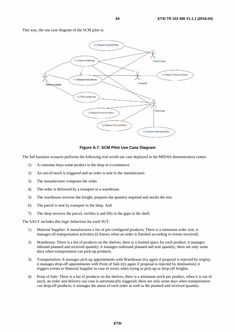
ETSI
ETSI TR 103 386 V1.1.1 (2016-04) 64
This way, the use case diagram of the SCM pilot is:
Figure A.7: SCM Pilot Use Case Diagram
The full business scenario performs the following real-world use case deployed in the MIDAS demonstration centre:
1) A customer buys some product in the shop or e-commerce.
2) An out-of-stock is triggered and an order is sent to the manufacturer.
3) The manufacturer composes the order.
4) The order is delivered by a transport to a warehouse.
5) The warehouse receives the freight, prepares the quantity required and stocks the rest.
6) The parcel is sent by transport to the shop. And
7) The shop receives the parcel, verifies it and fills in the gaps in the shelf.
The SAUT includes this logic behaviour for each SUT:
1) Material Supplier: It manufactures a list of pre-configured products; There is a minimum order size; it manages all transportation activities (it knows when an order is finished according to events received).
2) Warehouse: There is a list of products on the shelves; there is a limited space for each product; it manages inbound planned and received quantity; it manages outbound planned and sent quantity; there are only some days when transportation can pick-up products.
3) Transportation: It manages pick-up appointments with Warehouse (try again if proposal is rejected by origin); it manages drop-off appointments with Point of Sale (try again if proposal is rejected by destination); it triggers events to Material Supplier in case of errors when trying to pick-up or drop-off freights.
4) Point of Sale: There is a list of products on the shelves; there is a minimum stock per product, when it is out of stock, an order and delivery use case is automatically triggered; there are only some days when transportation can drop-off products; it manages the status of each order as well as the planned and received quantity.

ETSI
ETSI TR 103 386 V1.1.1 (2016-04) 65
As a GS1 LIM compliant scenario is available, SUT components interchange messages according to GS1 LIM specification [i.34]. This way, the complexity of data types is great (on average more than 30 parameters per message), so that for a first proof of concept in order to facilitate the adoption of modelling techniques by pilot partners as well as to minimize the complexity for technical partners, a simplified version of SAUT has been developed. The SimpleSAUT reference implementation maintains the same logics but it reduces the complexity of message parameters, losing the GS1 LIM compliance.
As this pilot is in fact a test-bed service infrastructure, the deployment can be extensively configurable on demand. This way, the tester can deploy from all components in the same machine to every service in a different machine. All modules are configurable by their own files. There is an instance of the Logistics SAUT deployed in the public machine with the latest version of all components. The cloud version includes the installation of the usage-based monitor, provided by the project partner, which includes 1 monitor and 12 proxies, as it is shown in Figure A.8:
Figure A.8: Logistics SAUT Deployment in the cloud
A.2.2 Test configuration This clause contains the main results of the modelling phase developed with support of TMC partners. It details the MIDAS DSL compliant model of SCM SAUT. As the main purpose is to ensure that the SAUT is GS1 LIM [i.34] compliant, the test model has to include the interchange of messages between different SUTs, so interceptors and include loop and alt properties were added as combined fragments in the sequence diagrams, so that the model was becoming more difficult and required extra support from TMC. A set of diagrams of the model are shown as follows.

ETSI
ETSI TR 103 386 V1.1.1 (2016-04) 66
Figure A.9: SCM Test Configuration Model with Single Interceptors
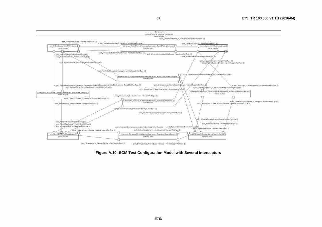
ETSI
ETSI TR 103 386 V1.1.1 (2016-04)67
Figure A.10: SCM Test Configuration Model with Several Interceptors

ETSI
ETSI TR 103 386 V1.1.1 (2016-04) 68
Figure A.11: SCM State Machines Diagram for Usage-based testing
Figure A.12: Some data types (simplest version with fewer parameters than GS1 standard)

ETSI
ETSI TR 103 386 V1.1.1 (2016-04) 69
Figure A.13: SCM Services Interfaces

ETSI
ETSI TR 103 386 V1.1.1 (2016-04) 70
Figure A.14: SCM Service Descriptions
A.2.3 Message flow scenarios As SCM pilot is based on a public specification, the business case follows this sequence diagram to become GS1 LIM [i.34] complaint.

ETSI
ETSI TR 103 386 V1.1.1 (2016-04) 71
Figure A.15: GS1 LIM [i.34] sequence diagram of the business case (use case orderAndDelivery)
In Figures A.16 to A.22 the sequence diagram of every use case according to GS1 LIM standard [i.34] is represented.

ETSI
ETSI TR 103 386 V1.1.1 (2016-04) 72
Figure A.16: GS1 LIM [i.34] sequence diagram of the use case Fill in Warehouse
Figure A.17: GS1 LIM [i.34] sequence diagram of the use case request inventory status

ETSI
ETSI TR 103 386 V1.1.1 (2016-04) 73
Figure A.18: GS1 LIM [i.34] sequence diagram of the use case request inbound status (to Warehouse)
Figure A.19: GS1 LIM [i.34] sequence diagram of the use case request inbound status (to Point of Sale)
Figure A.20: GS1 LIM [i.34] sequence diagram of the use case request outbound status

ETSI
ETSI TR 103 386 V1.1.1 (2016-04) 74
Figure A.21: GS1 LIM [i.34] sequence diagram of the use case request transport status
Figure A.22: GS1 LIM [i.34] sequence diagram of the use case transport and delivery
A.2.4 Manual execution For the manual execution a SAUT reference implementation was developed and deployed in midassaut.itainnova.es according to the GS1 LIM specification [i.34]. The full business scenario performs the following real-world use case, based on the assumption that the transportation activities are managed by the material supplier:
1) A customer buys some product in the shop or e-commerce
2) An out-of-stock is triggered and an order is sent to the manufacturer
3) The manufacturer composes the order
4) The order is delivered by a transport to a warehouse
5) The warehouse receives the freight, prepares the quantity required and stocks the rest
6) The parcel is sent by transport to the shop
7) The shop receives the parcel, verifies it and fills in the gaps in the shelf

ETSI
ETSI TR 103 386 V1.1.1 (2016-04) 75
The SAUT includes this logic behaviour for each SUT:
• Material Supplier
- It manufactures a list of pre-configured products
- There is a minimum order size
- It manages all transportation activities (it knows when an order is finished according to events received)
• Warehouse
- There is a list of products on the shelves
- There is a limited space for each product
- It manages inbound planned and received quantity
- It manages outbound planned and sent quantity
- There are only some days when transportation can pick-up products
• Transportation
- It manages pick-up appointments with Warehouse (try again if proposal is rejected by origin)
- It manages drop-off appointments with Point of Sale (try again if proposal is rejected by destination)
- It triggers events to Material Supplier in case of errors when trying to pick-up or drop-off freights
• Point of Sale
- There is a list of products on the shelves
- There is a minimum stock per product, when it is out of stock, an order and delivery use case is automatically triggered
- There are only some days when transportation can drop-off products
- It manages the status of each order as well as the planned and received quantity
At the moment the reference implementation includes a single version for each SUT component (Material Supplier, Warehouse, Transport and Point of Sale) but the architecture is ready to include some different instances for each component (some Material Suppliers, or Transport, or Warehouses or Point of Sales).
As there is a GS1 LIM [i.34] compliant scenario, SUT components interchange messages according to the GS1 LIM specification [i.34]. This way, the complexity of data types is high (on average more than 30 parameters per message), so that for a first proof of concept in order to facilitate the adoption of modelling techniques by pilot partners as well as to minimize the complexity for technical partners, a simplified version of SAUT was developed. The SimpleSAUT reference implementation maintains the same logics but it reduces the complexity of message parameters, losing the GS1 LIM [i.34] compliance. A list of service descriptions of this new implementation is available in the annex section of the present document. This simple version is replaced in the next increment by real GS1 LIM [i.34] compliant data types.
The first cloud version included a usage-based monitor and 4 proxies configured. In order to trace the usage of the SAUT, the monitor requires knowing the messages interchanged between all SUT components, but as some of them are sent by different SUTs, a new configuration was needed. For this reason a new scenario was configured, based on a single monitor and 12 proxies, one per incoming message.
As it is shown in Figure A.8, for instance, the Material Supplier service is deployed on port 8081, but for incoming messages from warehouse there is a proxy on port 8086, for messages sent by Transportation there is another proxy on port 8087 and there is a third proxy on port 8088 for point-of-sale requests.
A.2.5 Experiences In this clause preliminary results of Logistics pilot activities are described.
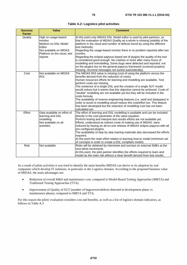
ETSI
ETSI TR 103 386 V1.1.1 (2016-04) 76
Table A.2: Logistics pilot activities
Success Factor
Value Comment
Quality High on usage-based monitor Medium on DSL Model Editor Not available on MIDAS Platform on the cloud, test reports
At this point only MIDAS DSL Model editor is used by pilot partners, so that the evaluation of MIDAS Quality as a whole is missing (stability of the platform in the cloud and number of defects found by using the different test methods). Regarding the usage-based monitor there is no problem reported after two months. Regarding the eclipse papyrus based set of plugins the quality of the tool is considered good enough. No crashes or locks after many hours of modelling and remodelling. Some bugs were detected and reported, not on the plugins but on the general papyrus framework (covered property missing, recv/snd messages not sorted automatically).
Cost Not available on MIDAS ROI
The MIDAS ROI value is missing (cost of using the platform versus the benefits derived from the reduction of costs). Human resources efforts for learning and modelling are available. Test perform costs are missing. The existence of a single DSL and the creation of a single SUT model would reduce but it seems that this objective cannot be achieved. Costs of "double" modelling are not available yet but they will be included in the costs formula. The availability of reverse engineering features (i.e. wsdl and datatypes) in order to avoid re-modelling would reduce this cost/effort too. This feature has been developed but the reduction of modelling cost has not been calculated yet.
Effort Data available on effort of learning and DSL modelling Not available on all activities
The effort of learning and DSL modelling is available and can be included directly in the cost parameter of the value equation. Perform testing and interpret test results efforts are not available yet. Efforts, understood as indirect costs of making use of MIDAS, were reduced by having an all-on-one release of MIDAS eclipse papyrus with all pre-configured plugins. The availability of step by step training materials also decreased the efforts required. At this point the main effort relates to learning how-to model (minimum set of concepts in order to create a DSL compliant model).
Risk Not available Risks will be obtained by interviews and surveys on external SMEs at the next pilots increments. At this point, the pilot partner identifies the efforts required to learn and model as the main risk without a clear benefit derived from test results.
As a result of pilots activities it was tried to identify the main benefits MIDAS can derive to its adoption by real companies which develop IT solutions, in particular in the Logistics domain. According to the proposed business value of MIDAS, the main advantages are:
• Reduction of overall R&D and maintenance cost, compared to Model-Based Testing Approaches (MBTA) and Traditional Testing Approaches (TTA).
• Improvement of Quality of SUT (number of bugs/errors/defects detected in development phase vs maintenance phase), compared to MBTA and TTA.
For this reason the pilots' evaluation considers cost and benefits, as well as a list of logistics domain indicators, as follows in Table A.3

ETSI
ETSI TR 103 386 V1.1.1 (2016-04) 77
Table A.3: Logistics domain indicators
Cost Indicator Value Comment Effort required in learning concepts, methods, technologies and tools to became an end-user of the MIDAS platform
2,8 PMs MIDAS DSL Adoption
Effort required in modelling the SAUT by using the MIDAS DSL and the UML-like tools provided by the project
1,2 PMs MIDAS DSL compliant model creation
Effort required in update the models into the cloud and perform the test campaign
Not available MIDAS on the cloud has not been used yet
Effort required in the interpretation of the test results in terms of bugs in the SAUT
Not available No test results are available yet
Reduction of cost compared to Traditional Testing Approaches
Not available
Reduction of cost compared to other Model-Based Testing Approaches
Not available
A.3 Automated test design example - e-Health Pilot
A.3.0 Overview
Information sharing among eHealth software systems has been one crucial point of investigation for years. Nowadays, the concepts of Electronic Health Record and Personal Health Record give rise to a whole set of applicative scenarios that stress the concept of sharing and communication even more. This has led to a significant awareness of the necessity of sharing information also among stakeholders and professionals.
Often the urge to integrate information has predominated over the clear-minded analysis of the big picture leading to severe bottlenecks and drawbacks in the adopted solutions. At the same time, wrong architectural choices have plagued the integration process and continue to hinder the existing solutions to keep with the pace of modern Internet scale requirements.
Social Networking and Big Data analytics have clearly demonstrated that storing, sharing and computing at Internet scale is now possible. Thus, the major interoperability issue for the systems in eHealth is to be able to cooperate in a loosely coupled, service oriented and scalable way with a whole world of possible counterparts.
In this context, the e-Health pilot of the MIDAS Project has the main goal to validate the expected advantages of the MIDAS prototypes, i.e. reduction of the overall R&D and maintenance costs of the software, improvement of the SUT quality according to Model-Based and Traditional Testing Approaches, in a real healthcare settings. The main goal is to demonstrate the mentioned improvement by providing a plausible yet simplified business scenario where complex service oriented architectures are employed.
In particular, the expectation of the Healthcare Pilot is to check the complex interactions that take place within a typical healthcare context where several actors, software modules and heterogeneous IT systems interact to achieve heterogeneous goals. In these contexts, interoperability issues are critical aspects of the overall software infrastructure deployment and, overall, it is difficult to identify these issues before delivery/deployment. As can be easily figured out, after-delivery, corrections are expensive and time consuming. Having the possibility to use a tool able to support developers in the systematic testing of the basic healthcare processes, at both syntactic and semantic levels, represents a valuable benefit for the improvement of both reliability and quality of the software packages delivered.
A.3.1 e-Health Pilot The healthcare pilot is a service-oriented architecture deployed at the data centre of e-Health solution provider, company commercial. For the MIDAS Pilot, a dedicated virtual-lab was configured and is accessible through the web. Users can access a set of implementations of standard service specifications provided in the context of the HL7 - HSSP (Healthcare Service Specification Program) initiative, that is an open global community focused on improving health interoperability within and across organizations through the use of SOA and standard services.
NOTE: HSSP initiative - https://hssp.wikispaces.com/.
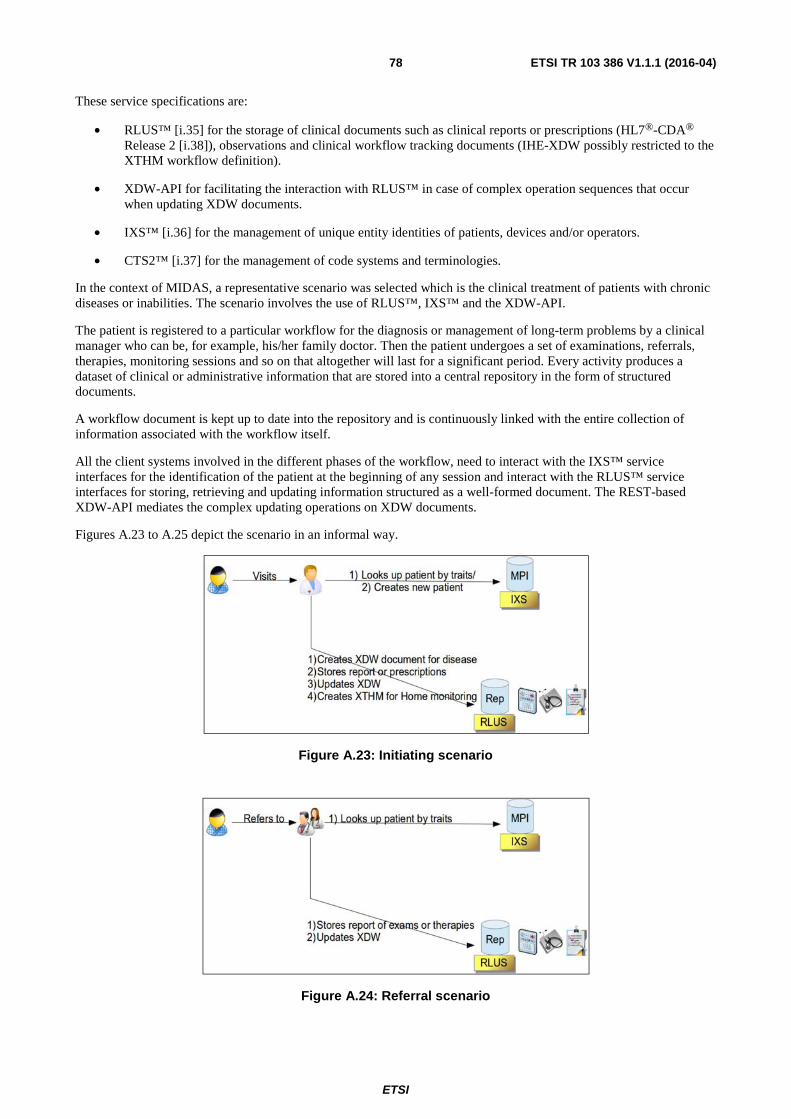
ETSI
ETSI TR 103 386 V1.1.1 (2016-04) 78
These service specifications are:
• RLUS™ [i.35] for the storage of clinical documents such as clinical reports or prescriptions (HL7®-CDA® Release 2 [i.38]), observations and clinical workflow tracking documents (IHE-XDW possibly restricted to the XTHM workflow definition).
• XDW-API for facilitating the interaction with RLUS™ in case of complex operation sequences that occur when updating XDW documents.
• IXS™ [i.36] for the management of unique entity identities of patients, devices and/or operators.
• CTS2™ [i.37] for the management of code systems and terminologies.
In the context of MIDAS, a representative scenario was selected which is the clinical treatment of patients with chronic diseases or inabilities. The scenario involves the use of RLUS™, IXS™ and the XDW-API.
The patient is registered to a particular workflow for the diagnosis or management of long-term problems by a clinical manager who can be, for example, his/her family doctor. Then the patient undergoes a set of examinations, referrals, therapies, monitoring sessions and so on that altogether will last for a significant period. Every activity produces a dataset of clinical or administrative information that are stored into a central repository in the form of structured documents.
A workflow document is kept up to date into the repository and is continuously linked with the entire collection of information associated with the workflow itself.
All the client systems involved in the different phases of the workflow, need to interact with the IXS™ service interfaces for the identification of the patient at the beginning of any session and interact with the RLUS™ service interfaces for storing, retrieving and updating information structured as a well-formed document. The REST-based XDW-API mediates the complex updating operations on XDW documents.
Figures A.23 to A.25 depict the scenario in an informal way.
Figure A.23: Initiating scenario
Figure A.24: Referral scenario

ETSI
ETSI TR 103 386 V1.1.1 (2016-04) 79
Figure A.25: Home-monitoring scenario
A.3.2 Test configuration For the automated test configuration it is crucial to provide all the PSM artefacts that specify the service architecture under test. This has been accomplished by delivering all the WSDLs and XSDs for every semantic signifier involved in the experimentation of MIDAS. These artefacts are the specialization of the original generic WSDLs/XSDs for RLUS™ and IXS™ defined in the HSSP technical specification body, namely OMG.
At the second stage architectural test configuration diagrams have been delivered in two versions: UML-based MIDAS DSL and SCA.
In the MIDAS DSL use case all the datatypes, interfaces, ports and components were generated with an automatic procedure. This is fundamental in order to avoid the overwhelming efforts related to the typical complexity of healthcare related datatypes and with the scalability issue imposed by the generic service approach. Finally, as for the test configuration, one single diagram per HSSP service was produced.
Figure A.26 shows the RLUS™ test suite diagram containing the services specialized for three semantic signifiers (RLP, XDW, CDA2®) and the Metadata interface.
As can be seen, the Testsuite component is profiled to be a UTP TestContext.
Figure A.26: RLUS™ test suite diagram

ETSI
ETSI TR 103 386 V1.1.1 (2016-04) 80
Figure A.27 shows the test suite for the IXS™ service with one semantic signifiers and the metadata interface.
Figure A.27: IXS™ test suite diagram
Moreover, two atomic participants SCA models and one Composite SCA diagram for the overall SAUT scenario were proposed and assessed.
This reflects the second approach available in MIDAS, named SCA4SAUT, for modelling the SAUT architecture using SCA and SCXML diagrams.
The two atomic participants are:
• MPI (Master Patient Index), which implements the IXS™ service interfaces (Management and Query or shortly MQ, Admin) for the semantic signifier POCDPatient plus its MetadataInterface.
• Repository, which implements the Management and Query Interface (shortly MQ) based on the RLUS™ specification for the two semantic signifiers CDA2® and XDW plus its MetadataInterface.
Since there are no particular relations among the services in the eHealth scenario, because all of them work independently from each other, a proper client-based orchestration of the message flow was assumed for the SAUT. This scenario simulates a portal-like interaction where the two atomic participants are orchestrated in a typical interaction use case described in Figures A.23, A.24 and A.25. According to this approach, a portal composite participant was designed.
Figures A.28, A.29 and A.30 show the SCA diagrams.
Figure A.28: SCA diagram of the IXS™ service

ETSI
ETSI TR 103 386 V1.1.1 (2016-04) 81
Figure A.29: SCA diagram of the RLUS™ service
The portal composite participant SCA diagram is shown in Figure A.30.
Figure A.30: SCA diagram of the PORTAL
Besides modelling the SAUT and the test context architecture, other preliminary activities were related to configuring the pilot for test configuration.
In order to be able to exploit Usage Based Testing (UBT) techniques for generating test cases, a usage journal of the services had to be recorded. Usage journal consists of log files tracking all the requests and responses generated by the interaction with the services at transport level in a given period. To this purpose, a monitoring tool called AutoQuest, provided by a project partner, was installed in strategic points of the deployed SoA. Approximately 1 Gb of log data was recorded and used for UBT tuning procedures.
To fully support automated test generation and execution, so called auxiliary services were instantiated. These services, called stateViews (and recorded for example as properties in the SCA models), were implemented and are used to:
1) Reset the internal state of a service implementation in order to re-execute test cases always from the same initial state
2) Extract a resume of the service internal state in order to cross compare the correctness of a service interaction with its actual effects of the service implementation's internal state.

ETSI
ETSI TR 103 386 V1.1.1 (2016-04) 82
A.3.3 Message flow scenarios The message flow of the portal-like scenario has been depicted in Figure A.31 as a state machine.
Figure A.31: State machine representation of the portal-like scenario
1) The flow is initiated by a findIdentitiesByTraits, which is sent to the MPI (IXS™ MQ interface) in order to retrieve a patient context.
2) If the patient is found, the flow continues to point 4. Otherwise, a new patient context is created with the createIdentityFromEntity operation (IXS™ MQ Interface).
3) Accordingly, a new Workflow Document is created for the patient in order to track his pathway through a clinical process. A new XDW document is stored into the repository using the put operation of the RLUS™ MQ Interface.
4) The system enters an idle state waiting for incoming clinical documents (CDA2 reports) through the RLUS™ MQ Interface.
5) When a new ClinicalDocument (CDA2 report) is stored through an RLUS™ MQ put operation, the system retrieves the corresponding workflow document (get operation on RLUS™ MQ) and updates it accordingly in order to track the documented clinical activity. The workflow document is stored back into the repository replacing the previous version.
6) If the new ClinicalDocument is recognized to be a closing action, the workflow document is closed and the state machine reaches the final state.
In order to correctly use the functional test procedures, it is important to provide a formalized vision of the state machine that reflects the scenario. The present document was created using the SCXML format, as shown below.
<?xml version="1.0"?> <scxml xmlns:xsi="http://www.w3.org/2001/XMLSchema-instance" xsi:schemaLocation="http://www.w3.org/2005/07/scxml http://www.w3.org/2011/04/SCXML/scxml.xsd" xmlns="http://www.w3.org/2005/07/scxml" initial="initial" name="fullportal_edited.psm" version="1.0"> <!-- version in which the patient is not found (a stimulator component can only have 1 stimulus type) --> <datamodel> <data id="stimulus_payload" src="findIdentitiesByTraits.xml"/> <!-- find -->

ETSI
ETSI TR 103 386 V1.1.1 (2016-04) 83
<data id="createIdentityFromEntity" src="createIdentityFromEntity.xml"/> <data id="cda2report_put" src="cda2report_put.xml"/> <data id="xdw_create" src="xdw_create.xml"/> <data id="xdw_retrieve" src="xdw_retrieve.xml"/> <data id="xdw_update" src="xdw_update.xml"/> <data id="first_time_idle" expr="true"/> <data id="update_count" expr="2"/> </datamodel> <state id="initial"> <!-- first action of the scenario. Search a patient --> <transition target="SEARCH_PATIENT_STATE"> <log expr="'Initial stimulus for lookup'"/> <send eventexpr="'POCDPatientMQReference::findIdentitiesByTraits::input'" namelist="stimulus_payload"/> </transition> </state> <state id="SEARCH_PATIENT_STATE"> <!-- patient not found, ask for creation --> <transition event="POCDPatientMQReference::findIdentitiesByTraits::output" target="CREATE_PATIENT_STATE" cond="_event.data.getElementsByTagName('statusSuccess').item(0).getTextContent() == 'false'"> <log expr="'Patient not found, going to patient create state'" /> <send eventexpr="'POCDPatientMQReference::createIdentityFromEntity::input'" namelist="createIdentityFromEntity"/> </transition> <!-- patient found, go to idle state --> <transition event="POCDPatientMQReference::findIdentitiesByTraits::output" target="IDLE_STATE" cond="_event.data.getElementsByTagName('statusSuccess').item(0).getTextContent() == 'true'"> <log expr="'Patient found, going to idle state'" /> </transition> </state> <state id="CREATE_PATIENT_STATE"> <!-- response of the creation (assumed OK), put it to RLUS_XDW interface --> <transition event="POCDPatientMQReference::createIdentityFromEntity::output" target="CREATE_XDW_STATE"> <log expr="'Patient created now create workflowdocument'" /> <send eventexpr="'RLUSXDWReference::put::input'" namelist="xdw_create"/> </transition> </state> <state id="CREATE_XDW_STATE"> <!-- patient putted to RLUS_XDW, go to idle state --> <transition event="RLUSXDWReference::put::output" target="IDLE_STATE"> <log expr="'Update workflowdocument'" /> </transition> </state> <!-- update loop, composed of 3 steps --> <!-- step1: ask to retrieve patient informations --> <state id="IDLE_STATE"> <!-- transition taken when entering in this state for the first time. Retrieve patient informations --> <transition cond="first_time_idle == true" target="RETRIEVE_XDW_STATE"> <assign name="first_time_idle" expr="false"/> <log expr="'First idle time, retrieving patient workflow...'"/> <send eventexpr="'RLUSCDA2ReportReference::put::input'" namelist="cda2report_put"/> </transition> <!-- transition taken while update looping. Retrieve patient informations --> <transition event="RLUSXDWReference::put::output" target="RETRIEVE_XDW_STATE"> <log expr="'Upon receipt of a Clinical report proceed to retrieve workflow for update'"/> <send eventexpr="'RLUSCDA2ReportReference::put::input'" namelist="cda2report_put"/> </transition> </state> <!-- step2: successfully retrieve patient informations --> <state id="RETRIEVE_XDW_STATE"> <!-- Patient informations retrieved, proceding to update the patient informations --> <transition event="RLUSCDA2ReportReference::put::output" target="UPDATE_XDW_STATE"> <log expr="'Workflow retrieved. Proceed to updating'"/> <send eventexpr="'RLUSXDWReference::get::input'" namelist="xdw_retrieve"/> </transition> </state>

ETSI
ETSI TR 103 386 V1.1.1 (2016-04) 84
<!-- step3: update patient informations --> <state id="UPDATE_XDW_STATE"> <!-- update and loop to idle state (not closing) --> <transition event="RLUSXDWReference::get::output" target="IDLE_STATE" cond="update_count > 0"> <assign name="update_count" expr="update_count - 1"/> <log expr="'Workflow updated. Update is not closing go back to idle'" /> <send eventexpr="'RLUSXDWReference::put::input'" namelist="xdw_update"/> </transition> <!-- update and close --> <transition event="RLUSXDWReference::get::output" target="CLOSING_STATE" cond="update_count == 0"> <log expr="'Workflow updated. Update is closing so close PSM'" /> </transition> </state> <!-- finished updating loop, closing --> <state id="CLOSING_STATE"> <transition target="final" /> </state> <final id="final"/> </scxml>
A.3.4 Automated execution In this clause, the two approaches for automating test generation and execution are shown. One for the execution guided by UML-based models and the other by using the SCA4SAUT/SCXML models.
In the UML based approach the models defined with the Papyrus tool are stored as XMI files. The models are then uploaded into the MIDAS TaaS file system, bundled with the usage journals if UBT has to be employed.
When fuzzy methods are to be employed, it is recommended to add more models that refine the fuzzyfication strategies. These models are expressed as UML sequence diagrams and, in the eHealth pilot, the message exchanges are all synchronous.
The sequence diagrams were designed using the same UML modelling tool as the SAUT models and are bundled together as XMI files. Figures A.32, A.33 and A.34 show examples of sequence diagrams modelling two interactions with IXS™ MQ interface, one interaction with RLUS™ MQ interface and one interaction with RLUS™ Metadata interface.
Figure A.32: Sequence diagrams modelling two interactions with IXS™ MQ interface

ETSI
ETSI TR 103 386 V1.1.1 (2016-04) 85
Figure A.33: Sequence diagrams modelling one interaction with RLUS™ MQ
Figure A.34: Sequence diagrams modelling one interaction with RLUS™ Metadata interface
At this stage, the proper TestGenAndRun method has to be called through the MIDAS TaaS interfaces and this starts a rather lengthy asynchronous process of generation, compilation and execution of test cases.
A.3.5 Experiences At the time of writing, the MIDAS TaaS is in the phase of finalization, therefore the complete automated test generation use case has not been achieved so far. The preliminary experiences are mainly related to the modelling and auxiliary activities. In particular, there is no complete assessment of the fully automated test scenario yet since the pilot has not yet been able to generate executable TTCN code from the supplied models and PSM artefacts.
Modelling with the UML-based language could be quite overwhelming for typical industrial context. Especially when considering that many technical descriptions of a SoA are usually already available in the form of WSDL, XSD, Schematrons and in some cases even UML models. In particular, the datatypes modelling is very expensive and it is hardly reusable or shareable because there is still a severe interoperability issue among the different UML modelling tools.
The effort spent by the MIDAS development team to realize a WSDL/XSD importer that transforms all data and component structures into UML significantly, enhances the ratio between automated vs manual activities.

ETSI
ETSI TR 103 386 V1.1.1 (2016-04) 86
To summarize, the most significant issues that are currently open to assess the automated use case are:
1) Is the datatype importer stable enough to face all the challenges posed by the very complex models available in XSD and that could be used in a scenario like the eHealth Pilot where generic services are employed? Currently the complexity impedance between XSD and UML is the major cause that has blocked the generation of TTCN code for the healthcare pilot. It is fundamental that this importer becomes stable and the import of datatypes fully automated in order to be able to achieve a positive result for the automated use case.
2) The journal that is used for generating test cases for the usage based testing cannot be used (or only to a certain degree) for the security based testing. This causes the MIDAS user who wants to deploy security-testing procedures, to explicitly draw sequence diagrams and instance specifications for the generation of test cases, thus reducing significantly the benefit of the automated testing use-case.
The SCA4SAUT/SCXML approach, was considered to be somehow a more bottom-up approach, it works by associating with the already available PSM level information, and other lower level models based on XML (SCA and SCXML). From a developer point of view, this is surely a straightforward and more interoperable approach because it eliminates ambiguities related to graphical models, simplifies the editing of artefacts and in general allows the treatment of the models with the same techniques and procedures adopted for source code management.
Anyway, the current lack of a commonly accepted graphical formalism could represent an obstacle to its adoption by people without specific technical skills.
Moreover, as this approach is based on rather novel standards (particularly true for SCXML), it appears that there are still some issues to be faced in the relation between described artefacts and functionalities inside MIDAS.
Currently there is no possibility to fully assess the automated testing use case with this tool stack mainly because of technical issues related to the advanced functionalities, like intelligent planner and scheduler of test cases. Anyway, the lower impedance among the adopted models and the PSM level artefacts will probably be a positive key factor in the final demonstration and, possibly, in a future commercial exploitation.
Regarding the installation and implementation of extra tooling, an important consideration is that the installation of software in the form of HTTP proxies into an operating SoA could be an issue which challenges and violates company or customer security policies. In this case, the creation of a usage journal for UBT could become a complex issue. The implementation of state-view auxiliary services also presents some impact on the SoA, but since the approach is service oriented and optional, the assumption was made of a smaller impact compared to the first approach.
Finally, interfaces for accessing service implementations' internal state are in general already present and they can typically be reused and adapted. The biggest issue, in this case, is the requirement that those services have a WS* based interface. In order to reduce the burden on SoA developers and maintainers, it could be useful to adapt MIDAS services to use also REST-based auxiliary services.

ETSI
ETSI TR 103 386 V1.1.1 (2016-04) 87
History
Document history
V1.1.1 April 2016 Publication