tr 102 300-3 - v1.2.1 - terrestrial trunked radio (tetra - etsi
TRANSCRIPT

ETSI TR 102 300-3 V1.2.1 (2002-01)
Technical Report
Terrestrial Trunked Radio (TETRA);Voice plus Data (V+D);
Designers' guide;Part 3: Direct Mode Operation (DMO)

ETSI
ETSI TR 102 300-3 V1.2.1 (2002-01)2
Reference RTR/TETRA-01011-3
Keywords radio, TETRA
ETSI
650 Route des Lucioles F-06921 Sophia Antipolis Cedex - FRANCE
Tel.: +33 4 92 94 42 00 Fax: +33 4 93 65 47 16
Siret N° 348 623 562 00017 - NAF 742 C
Association à but non lucratif enregistrée à la Sous-Préfecture de Grasse (06) N° 7803/88
Important notice
Individual copies of the present document can be downloaded from: http://www.etsi.org
The present document may be made available in more than one electronic version or in print. In any case of existing or perceived difference in contents between such versions, the reference version is the Portable Document Format (PDF).
In case of dispute, the reference shall be the printing on ETSI printers of the PDF version kept on a specific network drive within ETSI Secretariat.
Users of the present document should be aware that the document may be subject to revision or change of status. Information on the current status of this and other ETSI documents is available at
http://portal.etsi.org/tb/status/status.asp
If you find errors in the present document, send your comment to: [email protected]
Copyright Notification
No part may be reproduced except as authorized by written permission. The copyright and the foregoing restriction extend to reproduction in all media.
© European Telecommunications Standards Institute 2002.
All rights reserved.

ETSI
ETSI TR 102 300-3 V1.2.1 (2002-01)3
Content
Intellectual Property Rights ..............................................................................................................................10
Foreword...........................................................................................................................................................10
1 Scope ......................................................................................................................................................11
2 References ..............................................................................................................................................11
3 Definitions, symbols and abbreviations .................................................................................................12 3.1 Definitions........................................................................................................................................................12 3.2 Symbols............................................................................................................................................................14 3.3 Abbreviations ...................................................................................................................................................14
4 What is direct mode and why do we need it?.........................................................................................15 4.1 General .............................................................................................................................................................15 4.2 Frequency of operation.....................................................................................................................................17 4.3 Managed Direct Mode......................................................................................................................................17 4.4 Direct mode on European shared harmonized spectrum ..................................................................................18
5 Direct mode services and facilities.........................................................................................................18 5.1 Service definitions............................................................................................................................................18 5.1.1 Teleservice..................................................................................................................................................18 5.1.2 Bearer service .............................................................................................................................................19 5.1.3 Intrinsic service...........................................................................................................................................19 5.1.4 Summary of tele/bearer services offered in TETRA DMO ........................................................................19 5.2 Direct mode teleservices ..................................................................................................................................20 5.2.1 Individual call .............................................................................................................................................20 5.2.2 Group call ...................................................................................................................................................20 5.3 Direct mode bearer services .............................................................................................................................20 5.3.1 Circuit mode unprotected bearer services ...................................................................................................20 5.3.2 Circuit mode protected bearer services .......................................................................................................21 5.3.3 Short Data Service (SDS) ...........................................................................................................................21 5.4 Intrinsic services...............................................................................................................................................22 5.4.1 DM late entry..............................................................................................................................................22 5.4.2 Transmitting party identification ................................................................................................................22 5.4.3 Emergency calls..........................................................................................................................................22 5.4.4 OTAR .........................................................................................................................................................22
6 Description of direct mode equipment types..........................................................................................23 6.1 General .............................................................................................................................................................23 6.2 Direct mode mobile station (DM-MS) .............................................................................................................24 6.3 Dual watch mobile station (DW-MS)...............................................................................................................24 6.4 Direct mode repeater (DM-REP)......................................................................................................................25 6.5 Direct mode gateway (DM-GATE)..................................................................................................................26 6.6 Direct mode repeater/gateway combination (DM-REP/GATE).......................................................................26 6.7 Direct mode power classes ...............................................................................................................................27 6.8 Limitations imposed by the physical layer for direct mode type equipment ....................................................27
7 Direct mode operational examples .........................................................................................................28 7.1 General .............................................................................................................................................................28 7.2 MS to MS communication with full Dual Watching........................................................................................29 7.3 DMO communication via a repeater with full Dual Watching.........................................................................29 7.4 Gateway operation............................................................................................................................................30 7.5 Direct mode repeater/gateway operation..........................................................................................................32
8 Outline of direct mode protocols............................................................................................................33 8.1 OSI reference model.........................................................................................................................................33 8.2 TDMA frame and slot structure for direct mode operation ..............................................................................33 8.2.1 Frame structure ...........................................................................................................................................34 8.2.2 Timeslots and bursts ...................................................................................................................................34 8.3 Physical layer functionality ..............................................................................................................................35

ETSI
ETSI TR 102 300-3 V1.2.1 (2002-01)4
8.4 Single call protocols .........................................................................................................................................36 8.4.1 MS-MS Normal Mode ................................................................................................................................36 8.4.2 Repeater type 1A ........................................................................................................................................36 8.4.3 Repeater type 1B.........................................................................................................................................37 8.4.4 Gateway ......................................................................................................................................................37 8.4.5 Repeater/Gateway types 1A and 1B ...........................................................................................................37 8.5 Two call protocols ............................................................................................................................................38 8.5.1 MS-MS frequency efficient mode ..............................................................................................................38 8.5.2 Repeater type 2 ...........................................................................................................................................39 8.6 Choosing the repeater type ...............................................................................................................................39 8.6.1 Background.................................................................................................................................................39 8.6.2 Mobile trunked mode base station ..............................................................................................................39 8.6.2.1 Advantages of using a stand-alone mobile trunked mode base station for repeater operation..............40 8.6.2.2 Disadvantages of using a stand-alone mobile trunked mode base station for repeater operation .........40 8.7 Co-existence with trunked mode ......................................................................................................................40 8.7.1 General........................................................................................................................................................40 8.7.2 Type 1A DM-REP in TM-BS transmit band ..............................................................................................41 8.7.3 Type 1A DM-REP in TM-BS receive band................................................................................................42 8.7.4 Type 1B or type 2 DM-REP transmitter in TM-BS transmit band .............................................................43 8.7.5 Type 1B or type 2 DM-REP transmitter in TM-BS receive band...............................................................44 8.7.6 DM-REP and DM-MSs far from TM-BS and TM-MSs .............................................................................45 8.7.7 DM-REP and DM-MSs far from TM-BS, close to TM-MSs .....................................................................45 8.7.8 DM-REP and DM-MSs close to TM-BS, far from TM-MSs .....................................................................46 8.7.9 DM-REP and DM-MSs close to TM-BS and TM-MSs..............................................................................46 8.8 Co-existence with direct mode MS-MS operation ...........................................................................................47 8.8.1 General........................................................................................................................................................47 8.8.2 MS-MS call in type 1B DM-REP uplink band ...........................................................................................47 8.8.3 MS-MS call in type 1B DM-REP downlink band ......................................................................................48 8.9 Direct mode frequency re-use ..........................................................................................................................49 8.9.1 General........................................................................................................................................................49 8.9.2 MS-MS call on type 1B DM-REP uplink frequency ..................................................................................50 8.9.3 MS-MS call on type 1B DM-REP downlink frequency .............................................................................51 8.10 Implementation and operation issues affecting dual watch ..............................................................................52 8.10.1 General........................................................................................................................................................52 8.10.2 Basis for dual watch operation....................................................................................................................52 8.10.3 Implementation of dual watch operation ....................................................................................................53 8.10.3.1 Switching from idle to active ................................................................................................................53 8.10.3.2 Switching from active to active.............................................................................................................54 8.11 Channel surveillance ........................................................................................................................................55 8.12 Battery economy ..............................................................................................................................................55 8.13 Testable boundaries..........................................................................................................................................56
9 Security features.....................................................................................................................................56 9.1 General .............................................................................................................................................................56 9.2 Authentication ..................................................................................................................................................56 9.2.1 Mobile to mobile operation.........................................................................................................................56 9.2.2 Dual Watch Operation ................................................................................................................................56 9.2.3 Gateway mode operation ............................................................................................................................56 9.3 Confidentiality..................................................................................................................................................57 9.3.1 Air Interface (AI) encryption ......................................................................................................................57 9.3.1.1 Cipher Key ............................................................................................................................................57 9.3.1.2 The Time Variant Parameter (TVP)......................................................................................................57 9.3.2 End-to-end encryption ................................................................................................................................58 9.4 Key Management .............................................................................................................................................58 9.4.1 Air Interface Encryption keys.....................................................................................................................58 9.4.2 End to End Encryption keys .......................................................................................................................58 9.4.3 Over The Air Re-keying (OTAR)...............................................................................................................58 9.5 Secure Enable and Disable ...............................................................................................................................58
10 Radio Aspects.........................................................................................................................................58 10.1 DMO deployment constraints...........................................................................................................................58 10.2 Transmitter noise..............................................................................................................................................59

ETSI
ETSI TR 102 300-3 V1.2.1 (2002-01)5
10.3 Blocking ...........................................................................................................................................................61 10.4 Effects of transmitter noise and blocking .........................................................................................................61 10.5 Methodology ....................................................................................................................................................61 10.5.1 Assumptions ...............................................................................................................................................63 10.5.2 Calculating the effect of transmitter noise ..................................................................................................63 10.5.3 Calculating the effect of blocking...............................................................................................................63 10.5.4 Allowing for a noise floor uplift .................................................................................................................63 10.5.5 Translating path losses into distances .........................................................................................................64 10.6 Example 1 - wanted signal at extremity of range, unwanted interferer close by..............................................65 10.6.1 Step 1 - Calculate allowable noise ..............................................................................................................65 10.6.2 Step 2 - Translate allowable noise into path loss and stay-away distance ..................................................65 10.6.3 Step 3 - Calculate path loss and stay-away distance for blocking...............................................................65 10.7 Example 2 - wanted signal at close range, unwanted interferer close by .........................................................66 10.7.1 Step 1 - Calculate noise floor uplift ............................................................................................................66 10.7.2 Step 2 - Calculate allowable noise ..............................................................................................................66 10.7.3 Step 3 - Translate allowable noise into path loss and stay-away distance ..................................................66 10.7.4 Step 4 - Calculate path loss and stay-away distance for blocking...............................................................66 10.8 Unwanted transmission noise versus blocking .................................................................................................67 10.9 Variation of stay-away distance with transmitter power and frequency separation .........................................68 10.10 Effect of assumptions .......................................................................................................................................69 10.11 Implementation issues ......................................................................................................................................69 10.12 Recommended frequency separation for DMO MS-MSs.................................................................................72
11 Operational scenarios .............................................................................................................................72 11.1 Range extension scenario using type 1A repeater ............................................................................................72 11.2 Range extension scenarios using a gateway .....................................................................................................74 11.3 DMO range extension scenario with link into TMO Dispatcher using a type 1B repeater/gateway ................76 11.4 DMO range extension scenario with link into TMO Dispatcher using a gateway ...........................................77 11.5 Range extension inside buildings using a type 2 repeater ................................................................................78
Annex A: Teleservices, bearer and supplementary services supported by TMO/DMO..................80
Annex B: Short range propagation models used in the co-existence studies....................................81
B.1 Introduction ............................................................................................................................................81
B.2 Free space propagation...........................................................................................................................81
B.3 Bacon model...........................................................................................................................................82
B.4 CEPT SE21 model .................................................................................................................................83
B.5 Discussion ..............................................................................................................................................85
Annex C: Trial results for short range propagation model and comparison between theoretical and measured stay-away distances...................................................................88
C.1 Introduction ............................................................................................................................................88
C.2 Results of the trials .................................................................................................................................88
C.3 Assumptions of the theoretical calculations...........................................................................................89
C.4 Propagation model..................................................................................................................................91
C.5 Losses between receiver and transmitters ..............................................................................................91
C.6 Reduction in voice quality......................................................................................................................93
C.7 Measured transmitter losses and the decreased margin..........................................................................94
C.8 The assumption of linearity....................................................................................................................95
C.9 Conclusions and discussion....................................................................................................................97
C.10 Quantitative assessment .........................................................................................................................98
Annex D: RF channel selection, numbering and addressing..............................................................99

ETSI
ETSI TR 102 300-3 V1.2.1 (2002-01)6
D.1 Background ............................................................................................................................................99
D.2 Numbering..............................................................................................................................................99
D.3 Addressing in repeater and gateway direct mode operation.................................................................100
D.4 Summary ..............................................................................................................................................100
Annex E: Detailed direct mode protocols ..........................................................................................101
E.1 General .................................................................................................................................................101
E.2 MS-MS direct mode normal operation.................................................................................................101 E.2.1 DM protocol layering .....................................................................................................................................101 E.2.2 MS-MS direct mode functionality..................................................................................................................102 E.2.3 MS-MS physical resources.............................................................................................................................102 E.2.4 Slot timing diagrams ......................................................................................................................................102 E.2.4.1 Constraints on the frame structure (including synchronization) ...............................................................103 E.2.4.2 Direct mode operation ..............................................................................................................................103 E.2.5 MS-MS call set-up protocol ...........................................................................................................................104 E.2.5.1 MS-MS call set-up without presence check..............................................................................................104 E.2.5.2 MS-MS call set-up time (fundamental constraints) ..................................................................................105 E.2.5.3 MS-MS call set-up with presence check...................................................................................................105 E.2.6 Late entry........................................................................................................................................................105 E.2.7 Channel reservation and changeover in a call ................................................................................................106 E.2.8 Pre-emption of a DM call ...............................................................................................................................107 E.2.9 Terminating a call...........................................................................................................................................108 E.2.10 DM short data call ..........................................................................................................................................108 E.2.10.1 Unacknowledged short data message .......................................................................................................108 E.2.10.2 Acknowledged short data message ...........................................................................................................108 E.2.11 Implementation issues ....................................................................................................................................109 E.2.11.1 Configuration............................................................................................................................................109 E.2.11.2 Calling/dialling procedures.......................................................................................................................109
E.3 Repeater Type 1A.................................................................................................................................110 E.3.1 DM protocol layering .....................................................................................................................................110 E.3.2 Direct mode functionality...............................................................................................................................110 E.3.3 Physical resources ..........................................................................................................................................110 E.3.4 Slot timing diagrams ......................................................................................................................................110 E.3.4.1 Constraints on the frame structure (including synchronization) ...............................................................110 E.3.4.2 Direct mode operation ..............................................................................................................................110 E.3.5 Call set-up protocol ........................................................................................................................................111 E.3.5.1 Call set-up without presence check...........................................................................................................111 E.3.5.2 Call set-up time (fundamental constraints) ...............................................................................................112 E.3.5.3 Call set-up with presence check................................................................................................................112 E.3.6 Late entry........................................................................................................................................................113 E.3.7 Channel reservation and changeover in a call ................................................................................................113 E.3.8 Pre-emption of a DM call ...............................................................................................................................114 E.3.9 Terminating a call...........................................................................................................................................115 E.3.10 DM short data call ..........................................................................................................................................115 E.3.10.1 Unacknowledged short data message .......................................................................................................115 E.3.10.2 Acknowledged short data message ...........................................................................................................116 E.3.11 Implementation Issues ....................................................................................................................................117 E.3.11.1 Configuration............................................................................................................................................117 E.3.11.2 Calling/dialling procedures.......................................................................................................................118 E.3.11.3 Operational procedures .............................................................................................................................118 E.3.11.4 Constraints ................................................................................................................................................118
E.4 Repeater Type 1B.................................................................................................................................119 E.4.1 DM protocol layering .....................................................................................................................................119 E.4.2 Direct mode functionality...............................................................................................................................119 E.4.3 Physical resources ..........................................................................................................................................119 E.4.4 Slot timing diagrams ......................................................................................................................................119 E.4.4.1 Constraints on the frame structure (including synchronization) ...............................................................119

ETSI
ETSI TR 102 300-3 V1.2.1 (2002-01)7
E.4.4.2 Direct mode operation ..............................................................................................................................119 E.4.5 Call set-up protocol ........................................................................................................................................119 E.4.5.1 Call set-up without presence check...........................................................................................................119 E.4.5.2 Call set-up time (fundamental constraints) ...............................................................................................119 E.4.5.3 Call set-up with presence check................................................................................................................120 E.4.6 Late entry........................................................................................................................................................120 E.4.7 Channel reservation and changeover in a call ................................................................................................120 E.4.8 Pre-emption of a DM call ...............................................................................................................................120 E.4.9 Terminating a call...........................................................................................................................................120 E.4.10 DM short data call ..........................................................................................................................................120 E.4.10.1 Unacknowledged short data message .......................................................................................................120 E.4.10.2 Acknowledged short data message ...........................................................................................................120 E.4.11 Implementation Issues ....................................................................................................................................120 E.4.11.1 Configuration............................................................................................................................................120 E.4.11.2 Calling/dialling procedures.......................................................................................................................120 E.4.11.3 Operational procedures .............................................................................................................................120 E.4.11.4 Constraints ................................................................................................................................................120
E.5 Gateway................................................................................................................................................121 E.5.1 DM protocol layering .....................................................................................................................................121 E.5.2 Direct mode functionality...............................................................................................................................121 E.5.3 Physical resources ..........................................................................................................................................121 E.5.4 Slot timing diagrams ......................................................................................................................................121 E.5.4.1 Constraints on the frame structure (including synchronization) ...............................................................123 E.5.4.2 Direct mode operation ..............................................................................................................................123 E.5.5 Call set-up protocol ........................................................................................................................................123 E.5.5.1 Group call from V+D to DM-MS via a DM-GATE .................................................................................123 E.5.5.2 Group call from DM-MS via a DM-GATE ..............................................................................................125 E.5.5.3 Call set-up time (fundamental constraints) ...............................................................................................127 E.5.5.4 Individual call from V+D MS to DM-MS via a DM-GATE ....................................................................128 E.5.5.5 Individual call from DM-MS to V+D MS via a DM-GATE ....................................................................130 E.5.6 Late entry........................................................................................................................................................131 E.5.7 Channel reservation and changeover in a call ................................................................................................131 E.5.8 Pre-emption of a DM call ...............................................................................................................................133 E.5.9 Terminating a DM-GATE call .......................................................................................................................135 E.5.10 DM short data call ..........................................................................................................................................135 E.5.11 Implementation Issues ....................................................................................................................................136 E.5.11.1 Configuration............................................................................................................................................136 E.5.11.2 Calling/dialling procedures.......................................................................................................................136 E.5.11.3 Operational procedures .............................................................................................................................137 E.5.11.4 Constraints ................................................................................................................................................137
E.6 Repeater/Gateway Type 1A .................................................................................................................137 E.6.1 DM protocol layering .....................................................................................................................................137 E.6.2 Direct mode functionality...............................................................................................................................137 E.6.3 Physical resources ..........................................................................................................................................138 E.6.4 Slot timing diagrams ......................................................................................................................................138 E.6.4.1 Constraints on the frame structure (including synchronization) ...............................................................138 E.6.4.2 Direct mode operation ..............................................................................................................................138 E.6.5 Group call from DM-MS via DM-REP/GATE ..............................................................................................138 E.6.6 Implementation Issues ....................................................................................................................................139 E.6.6.1 Configuration............................................................................................................................................139 E.6.6.2 Calling/dialling procedures.......................................................................................................................140 E.6.6.3 Operational procedures .............................................................................................................................141 E.6.6.4 Constraints ................................................................................................................................................141
E.7 Repeater/Gateway Type 1B..................................................................................................................141 E.7.1 DM protocol layering .....................................................................................................................................141 E.7.2 Direct mode functionality...............................................................................................................................141 E.7.3 Physical resources ..........................................................................................................................................141 E.7.4 Implementation Issues ....................................................................................................................................141 E.7.4.1 Configuration............................................................................................................................................141 E.7.4.2 Calling/dialling procedures.......................................................................................................................142

ETSI
ETSI TR 102 300-3 V1.2.1 (2002-01)8
E.7.4.3 Operational procedures .............................................................................................................................142 E.7.4.4 Constraints ................................................................................................................................................142
E.8 MS-MS frequency efficient operation..................................................................................................142 E.8.1 DM protocol layering .....................................................................................................................................142 E.8.2 Direct mode functionality...............................................................................................................................142 E.8.3 Physical resources ..........................................................................................................................................142 E.8.4 Slot timing diagrams ......................................................................................................................................142 E.8.4.1 Constraints on the frame structure (including synchronization) ...............................................................142 E.8.4.2 Direct mode operation ..............................................................................................................................142 E.8.5 Call set-up protocol ........................................................................................................................................143 E.8.5.1 Call set-up without presence check...........................................................................................................143 E.8.5.2 Call set-up time (fundamental constraints) ...............................................................................................143 E.8.5.3 Call set-up with presence check................................................................................................................143 E.8.6 Late entry........................................................................................................................................................143 E.8.7 Channel reservation and changeover in a call ................................................................................................144 E.8.8 Pre-emption of a DM call ...............................................................................................................................144 E.8.9 Terminating a call...........................................................................................................................................144 E.8.10 DM short data call ..........................................................................................................................................144 E.8.10.1 Unacknowledged short data message .......................................................................................................144 E.8.10.2 Acknowledged short data message ...........................................................................................................144 E.8.11 Implementation Issues ....................................................................................................................................144 E.8.11.1 Configuration............................................................................................................................................144 E.8.11.2 Calling/dialling procedures.......................................................................................................................144
E.9 Repeater Type 2 ...................................................................................................................................144 E.9.1 DM protocol layering .....................................................................................................................................144 E.9.2 Direct mode functionality...............................................................................................................................144 E.9.3 Physical resources ..........................................................................................................................................145 E.9.4 Slot timing diagrams ......................................................................................................................................145 E.9.4.1 Constraints on the frame structure (including synchronization) ...............................................................145 E.9.4.2 Direct mode operation ..............................................................................................................................145 E.9.5 Call set-up protocol ........................................................................................................................................145 E.9.5.1 Call set-up without presence check...........................................................................................................146 E.9.5.2 Call set-up time (fundamental constraints) ...............................................................................................147 E.9.5.3 Call set-up with presence check................................................................................................................147 E.9.6 Late entry........................................................................................................................................................148 E.9.7 Channel reservation and changeover in a call ................................................................................................148 E.9.8 Pre-emption of a DM call ...............................................................................................................................149 E.9.9 Terminating a call...........................................................................................................................................150 E.9.10 DM short data call ..........................................................................................................................................150 E.9.10.1 Unacknowledged short data message .......................................................................................................150 E.9.10.2 Acknowledged short data message ...........................................................................................................151 E.9.11 Implementation Issues ....................................................................................................................................152 E.9.11.1 Configuration............................................................................................................................................152 E.9.11.2 Calling/dialling procedures.......................................................................................................................152 E.9.11.3 Operational procedures .............................................................................................................................152 E.9.11.4 Constraints ................................................................................................................................................152
Annex F: Support of security features...............................................................................................153
F.1 Time Variant Parameter .......................................................................................................................153
F.2 Synchronization of end-to-end encryption ...........................................................................................153
Annex G: DMO user preferences for different configurations ........................................................154
G.1 Background ..........................................................................................................................................154
G.2 Conclusions from the DMO workshop ................................................................................................154 G.2.1 The existing DMO standards should be completed, supported and maintained .............................................154 G.2.2 Frequency Assignment for DMO ...................................................................................................................154 G.2.3 Frequency efficient mode ...............................................................................................................................154 G.2.4 TETRA Interoperability Profile (TIP) tests....................................................................................................155

ETSI
ETSI TR 102 300-3 V1.2.1 (2002-01)9
G.2.5 Further DMO features and facilities...............................................................................................................155 G.2.6 Direct mode and trunked mode inter-operation..............................................................................................155
Annex H: TETRA interoperability profiles (TIPs) for DMO ..........................................................156
H.1 Background ..........................................................................................................................................156
H.2 User input .............................................................................................................................................156
Annex I (informative): Bibliography.................................................................................................157
History ............................................................................................................................................................158

ETSI
ETSI TR 102 300-3 V1.2.1 (2002-01)10
Intellectual Property Rights IPRs essential or potentially essential to the present document may have been declared to ETSI. The information pertaining to these essential IPRs, if any, is publicly available for ETSI members and non-members, and can be found in ETSI SR 000 314: "Intellectual Property Rights (IPRs); Essential, or potentially Essential, IPRs notified to ETSI in respect of ETSI standards", which is available from the ETSI Secretariat. Latest updates are available on the ETSI Web server (http://webapp.etsi.org/IPR/home.asp).
Pursuant to the ETSI IPR Policy, no investigation, including IPR searches, has been carried out by ETSI. No guarantee can be given as to the existence of other IPRs not referenced in ETSI SR 000 314 (or the updates on the ETSI Web server) which are, or may be, or may become, essential to the present document.
Foreword This Technical Report (TR) has been produced by ETSI Project Terrestrial Trunked Radio (TETRA).
The present document is part 3 of a multi-part deliverable covering TETRA Voice plus Data Designers' Guide, as identified below:
ETR 300-1: "Overview, technical description and radio aspects";
ETR 300-2: "Radio channels, network protocols and service performance";
TR 102 300-3: "Direct Mode Operation (DMO)";
ETR 300-4: "Network management";
ETR 300-5 "Guidance on Numbering and addressing"

ETSI
ETSI TR 102 300-3 V1.2.1 (2002-01)11
1 Scope The present document is written as a "Read-me-first" manual or "Getting started with TETRA DMO". It is not intended to be a guide to the TETRA DMO standard nor an authoritative interpretation of the standard. If any conflict is found between the present document and the corresponding sections in the TETRA standard then the standard takes precedence.
The aims of the present document are:
• to provide the reader with sufficient knowledge to engage in qualified discussions with the equipment and service suppliers;
• to expose the reader to the specific language and technical terminology used in the standard;
• to enable the reader to understand the flexibility in system design, system network topography, system availability, various modes of operation and security features;
• in clause 10, sufficiently detailed design information is given to allow link budget calculations to be carried out and outline radio coverage planning to be performed. Some preliminary calculations are also given for co-existence between trunked and direct mode terminals and also for the number of direct mode talk groups (Nets) that can operate simultaneously at the same location.
The scope of this second version of the DMO Designers' Guide adds detailed consideration of repeaters and gateways to the detailed consideration of mobile station to mobile station direct mode operation which was covered in the first edition.
It should be understood that, as in all standardization activities, there is an inherent conflict between the users' wish to have as broad a standard as possible and at the same time wanting to have as much as possible of that broad standard available and implemented right from the beginning of service. Potential equipment purchasers, network operators and service users must make sure they influence the suppliers to have their required functionality available when they need it.
Equipment manufacturers will use the broad flexibility provided within the standard to develop and implement equipment in various ways, and still be conforming to the standard. This broad availability of equipment, each optimized around certain features and functionalities, needs to be carefully analysed by network operators and system users to find the supplier with equipment suited best for their needs.
2 References For the purposes of this Technical Report (TR) the following references apply:
[1] ETSI ETS 300 396-1: "Terrestrial Trunked Radio (TETRA); Technical requirements for Direct Mode Operation (DMO); Part 1: General network design".
[2] ETSI ETS 300 396-2: "Terrestrial Trunked Radio (TETRA); Technical requirements for Direct Mode Operation (DMO); Part 2: Radio aspects".
[3] ETSI ETS 300 396-3: "Terrestrial Trunked Radio (TETRA); Technical requirements for Direct Mode Operation (DMO); Part 3: Mobile Station to Mobile Station (MS-MS) Air Interface (AI) protocol".
[4] ETSI ETS 300 396-5: "Terrestrial Trunked Radio (TETRA); Technical requirements for Direct Mode Operation (DMO); Part 5: Gateway air interface".
[5] ETSI ETS 300 392-1: "Radio Equipment and Systems (RES); Trans-European Trunked Radio (TETRA) System; V+D Part 1: Network Aspects".
[6] ETSI EN 300 392-2: "Terrestrial Trunked Radio (TETRA); Voice plus Data (V+D); Part 2: Air Interface (AI)".

ETSI
ETSI TR 102 300-3 V1.2.1 (2002-01)12
[7] ETSI EN 300 392-5: "Radio Equipment and Systems (RES); Trans-European Trunked Radio (TETRA) System; V+D; Part 5: Vocoder".
[8] ETSI ETR 300-1 (1996): "Terrestrial Trunked Radio (TETRA); Voice plus Data (V+D); Designers' guide; Part 1: Overview, technical description and radio aspects".
[9] ETSI ETR 300-5: "Terrestrial Trunked Radio (TETRA); Voice plus Data (V+D); Designers' guide; Part 5: Guidance on Numbering and addressing".
[10] ITU-R Recommendation SM.329-6: "Spurious emissions".
[11] EPT/DMO PTG 010: "Suggestions on propagation models for TETRA scenarios" January 2001.
[12] UK Home Office Study No. 95/27/256/4/CS201: "TETRA RF Co-Existence Study Final Report June 1996 Telecom Consultants International (TCI)".
[13] ETSI EN 300 396 (all parts): "Terrestrial Trunked Radio (TETRA); Technical requirements for Direct Mode Operation (DMO)".
3 Definitions, symbols and abbreviations
3.1 Definitions For the purposes of the present document, the following terms and definitions apply:
call: Individual call or group call.
NOTE: These are slightly different for each type of direct mode but follow the same basic principles:
- individual call: complete sequence of related call transactions between two user MSs. There are always two participants in an individual call.
- group call: complete sequence of related call transactions involving two or more user MSs. The number of participants in a group call is not fixed, but is at least two. Participants may join (late entry) and leave an ongoing group call.
call transaction: all of the functions associated with a complete unidirectional transmission of information during a call
NOTE: A call is made up of one or more call transactions. In a simplex call these call transactions are sequential.
called user application: user application which receives an incoming call
calling user application: user application which initiates an outgoing call
carrier: See RF carrier.
changeover: within a call, process of effecting a transfer of the master role (and hence transmitting unit) at the end of one call transaction so that another can commence
channel: work or operational group selected by the user on the MS MMI
NOTE: See also DM channel.
Direct Mode Operation (DMO): mode of simplex operation where mobile subscriber radio units may communicate using radio frequencies which may be monitored by, but which are outside the control of, the TETRA V+D network
NOTE: Direct Mode Operation is performed without intervention of any base station.
DM Call Control (DMCC): layer 3 entity responsible for setting up and maintaining a call in DMO
DM channel: specific grouping of timeslots in the DM multiplex structure related to a particular DM RF carrier, i.e. DM frequency (or to a pair of duplex-spaced RF carriers for operation with a type 1B or type 2 DM-REP or a type 1B DM-REP/GATE)

ETSI
ETSI TR 102 300-3 V1.2.1 (2002-01)13
NOTE: The grouping may not always be fixed, but in DMO when operating in frequency efficient mode as an example, there are two DM channels, identified by the letters A and B.
Direct Mode Mobile Station (DM-MS): Physical grouping that contains all of the mobile equipment that is used to obtain TETRA DM services. A DM-MS may have one of three states:
• Master: if the DM-MS is active in a call transaction transmitting traffic or control data or is reserving the channel by means of channel reservation signalling;
• Slave: if the DM-MS is receiving traffic and/or signalling in a call;
• Idle: if the DM-MS is not in a call.
DM-REP presence signal: message transmitted by a DM-REP in order to indicate its presence on an RF carrier
Dual Watch Mobile Station (DW-MS): MS that is capable of both TETRA DMO and TETRA V+D operation
NOTE: In full dual watch a DW-MS is capable of periodically monitoring the V+D control channel while in a DM call, a DM RF carrier while in a V+D call and, when idle, of periodically monitoring both the DM RF carrier and the V+D control channel. In idle dual watch a DW-MS is not capable of monitoring the other channel while involved in an activity (e.g. a call), but, when idle, is still capable of periodically monitoring both the DM RF carrier and the V+D control channel.
DM GATEway (DM-GATE): device which provides gateway connectivity between DM-MS(s) and the TETRA V+D network
NOTE: The gateway provides the interface between TETRA DMO and TETRA V+D mode.
DM REPeater (DM-REP): device that operates in TETRA DMO and provides a repeater function to enable two or more DM-MSs to extend their coverage range
NOTE: It may be either a type 1 DM-REP, capable of supporting only a single call on the air interface, or a type 2 DM-REP, capable of supporting two calls on the air interface. A type 1 DM-REP may operate on either a single RF carrier (type 1A DM-REP) or a pair of duplex-spaced RF carriers (type 1B DM-REP). A type 2 DM-REP operates on a pair of duplex-spaced RF carriers.
DM REPeater/GATEway (DM-REP/GATE): device that combines the functions of a DM repeater and a DM gateway in a single implementation and is capable of providing both functions simultaneously (so that, during a call transaction initiated by a DM-MS, the DM-REP/GATE provides gateway connectivity to the TETRA V+D network and also provides a repeater function on the DM channel)
NOTE: The repeater part of the combined implementation may be either a type 1A repeater, operating on a single DM RF carrier, or a type 1B repeater, operating on a pair of duplex-spaced DM RF carriers.
frequency efficient mode: mode of operation where two independent DM communications are supported on a single RF carrier (or pair of duplex-spaced RF carriers for operation with a type 2 DM-REP)
NOTE: In frequency efficient mode the two DM channels are identified as channel A and channel B.
gateway: generic term used to describe either a pure DM-GATE or a combined implementation with a repeater (DM-REP/GATE)
logical channel: generic term for any distinct data path
NOTE: Logical channels are considered to operate between logical endpoints.
managed DMO: form of direct mode operation that requires authorization from the V+D infrastructure or a M-DMO authorizing unit in order for the DM-MS to be permitted to transmit
master link: communication link used for transmissions between master DM-MS and DM-REP or DM-REP/GATE
mobile trunked mode base station: trunked mode base station isolated from the SwMI but capable of single site trunking
NOTE: Such a BS can be rapidly located at an event or incident.
net: traditional name for a group call

ETSI
ETSI TR 102 300-3 V1.2.1 (2002-01)14
normal mode: mode of operation where only one DM communication is supported on an RF carrier (or pair of duplex-spaced RF carriers for operation with a type 1B DM-REP or type 1B DM-REP/GATE)
presence signal: signal transmitted by a gateway or a repeater in order to indicate its presence on a DM RF carrier
quarter symbol number: timing of quarter symbol duration 125/9 µs within a burst
recent user: DM-MS that was master of the call transaction immediately prior to the current master's call transaction in a call
recent user priority: service which gives the recent user preferred access to request transmission when the current master is ceasing its call transaction in a group call
NOTE: This service is controlled by the current master.
registration phase: period of time during which a gateway is actively soliciting registration requests
RF carrier: distinct radio frequency on which the DM channel may be active
simplex: mode of working in which information can be transferred in both directions but not at the same time
slave link: communication link used for transmissions between the DM-REP or DM-REP/GATE and slave DM-MSs
solicited registration: registration request which is made by a DM-MS during a registration phase initiated by a gateway
surveillance: process of determining the current state of the DM RF carrier when in idle mode
timebase: device which determines the timing state of signals transmitted by a DM-MS
type 1 DM-REP: DM repeater that supports a single call on the air interface
NOTE: There are two varieties of type 1 DM-REP. A type 1A DM-REP operates on a single RF carrier. A type 1B DM-REP operates on a pair of duplex-spaced RF carriers, one used as the "uplink" from DM-MSs to the DM-REP and the other used as the "downlink" from the DM-REP to DM-MSs.
type 2 DM-REP: DM repeater that is capable of supporting two simultaneous calls on the air interface
NOTE: A type 2 DM-REP operates on a pair of duplex-spaced RF carriers, one used as the "uplink" from DM-MSs to the DM-REP and the other used as the "downlink" from the DM-REP to DM-MSs.
unsolicited registration: registration request which is made by a DM-MS at any time other than within a registration phase
V+D operation: mode of operation for communication via the TETRA V+D air interface which is controlled by the TETRA Switching and Management Infrastructure (SwMI)
3.2 Symbols For the purposes of the present document, the following symbols apply:
Ud Direct Mode air interface Um Trunked Mode air interface
3.3 Abbreviations For the purposes of the present document, the following abbreviations apply:
BER Bit Error Rate BS Base Station CEPT Conférence Européenne des Postes et des Télécommunications DLB Direct mode Linearization Burst DLL Data Link Layer is a synonym for the whole layer 2 DM Direct Mode DM-GATE Direct Mode GATEway

ETSI
ETSI TR 102 300-3 V1.2.1 (2002-01)15
DM-MS Direct Mode Mobile Station DM-REP Direct Mode REPeater DM-REP/GATE Direct Mode REPeater/GATEway DMCC Direct Mode Call Control entity DMO Direct Mode Operation DNB Direct mode Normal Burst DO-MS Direct mode Only Mobile Station DSB Direct mode Synchronization Burst DU-MS DUal Mode (Trunked Mode/Direct Mode) Switchable Mobile Station DW-MS Dual Watch Mobile Station EU European Union GTSI Group TETRA Subscriber Identity HH Hand Held (mobile station) IOP InterOperability Profile ISSI Individual Short Subscriber Identity ITSI Individual TETRA Subscriber Identity M-DMO Managed Direct Mode Operation MAC Medium Access Control MMI Man Machine Interface MNI Mobile Network Identity (see note 1) MS Mobile Station (see note 2) MTM-BS Mobile Trunked Mode BS OTAR Over The Air Re-keying OUA Operator and Users Association (of the TETRA MoU) PDU Protocol Data Unit PNP Private Numbering Plan PTT Press To Talk switch, otherwise known as pressel SCK Static Cipher Key SDS Short Data Service SSI Short Subscriber Identity SwMI Switching and Management Infrastructure TDMA Time Division Multiple Access TE Terminal Equipment TIP TETRA Interoperability Profile TM Trunked Mode TMO Trunked Mode Operation TSI TETRA Subscriber Identity TVP Time Variant Parameter TxI Transmit Inhibit URT Usage Restriction Type V+D Voice plus Data (trunked infrastructure)
NOTE 1: These values may be different and their implementation different from other radio systems (such as GSM).
NOTE 2: The generic term MS includes hand portable and vehicular mounted radio terminals.
4 What is direct mode and why do we need it?
4.1 General Direct mode is a TETRA mode of operation in which two or more mobile stations communicate together without using the switching and management infrastructure (SwMI). This mode of operation is similar to the back-to-back operation of conventional half duplex radio schemes used by many existing private mobile radio systems such as that of the emergency services.
The use of direct mode is appropriate in the following situations:
• Rural areas with no infrastructure.

ETSI
ETSI TR 102 300-3 V1.2.1 (2002-01)16
• Urban areas with poor coverage e.g. in-building, car parks and underground.
• Covert and special operations.
• Contingency operational reasons e.g. when trunked system is not operational due to fault or is overloaded and the access time cannot be guaranteed.
• Secondary coverage from vehicle to handheld terminal.
Conventional back-to-back operation has the following disadvantages:
i) it leads to unstructured communications since the command structure cannot intervene;
ii) it leads to fragmented communications since there is no connection between back-to-back mobile stations and mobile stations using the infrastructure;
iii) it is not possible to record the communication.
The DMO capability standardized by ETSI overcomes these deficiencies in particular situations but to use the extended capability it will often be necessary to define operational procedures to ensure that the communication net is set up correctly. One of the purposes of the present document is to describe the extended functionality included in the DMO standard and to explain the basis of the procedures which must be put in place to make full use of this functionality.
As with all parts of the TETRA standard (V+D and DMO) the specification is not prescriptive about whether or how something must be implemented. All that the standard strives to achieve is compatibility between different implementations. Hence in many instances a particular user requirement may be stated to be "an implementation issue" i.e. it is supported by the protocol but how the functionality is invoked is left for the manufacturer and the user to agree.
Addressing the drawbacks of back-to-back operation identified above we will briefly outline the methods defined in the TETRA DMO standard for overcoming them. The technical terms used to define the functionality and the methods of achieving the desired objectives will become more apparent in the following clauses.
In all direct mode operation (remember that there are several types of DMO operation namely MS-MS, via a repeater and including a gateway) a pre-emption facility is included which allows higher priority direct mode MSs to seize the channel from lower priority users. If a gateway is included in the call then it is even possible for a dispatcher to take over the call.
The dual watch facility is of use when one of the radios in a local back-to-back group is within the range of the trunked system. By selectively listening in to the infrastructure it is possible for the MS in a back-to-back conversation group to be contacted if required by anyone else using the trunked system i.e. the DMO MS is contactable from the infrastructure if within range. In a similar way, if an MS operating in trunked mode is within range of its DMO talk group then it is able to dual watch on that group and be included in any calls that are set up (see note).
NOTE: It is possible to perform dual watch in today's conventional FDMA radio systems so long as the mobile is not in a call. The TDMA structure of DMO/V+D allows dual watch even within a call without losing any information, providing that the DW-MS is configured for full dual watch.
On point iii) above, if a DMO/TMO gateway is included in the DMO group then it is possible for the direct mode message exchanges to be recorded (so long as the transmitting MS is within range of the gateway).
In direct mode there are the normal issues of blocking and desensitization as suffered in conventional radio systems. These problems are however more acute for direct mode than trunked mode since there is no power control in direct mode (except repeater operation). Furthermore there is a potential for interference of the direct mode MSs with the trunked mode infrastructure leading to degraded performance of the trunked system. This is a problem that needs to be recognized and controlled if direct mode is to operate effectively within the coverage area of the trunked system. These issues are examined in clause 10.
Note however, that mutual interference is not a problem particular to TETRA. Similar effects are experienced with conventional analogue radio systems if operated in close proximity.

ETSI
ETSI TR 102 300-3 V1.2.1 (2002-01)17
4.2 Frequency of operation A major difference between TETRA trunked and direct mode operation is that in the latter only simplex voice operation is supported for both individual and group call operation (see note 1), and multi-slot circuit mode data is not allowed. There are other differences between the functionality supported by trunked and direct mode. This is summarized in annex A.
NOTE 1: In simplex operation only one party can speak at any time. The other party (or parties) must listen.
To minimize the risk of mutual interference it is desirable to provide frequency separation between the allocation for DMO and TMO services. This can be achieved by operating DMO in a sub-band at one end of each of the available TETRA allocations (see example in figure 1). This has been proposed for internationally agreed common channels but for national use each country is also free to allocate DMO channels within the BS transmit and BS receive bands.
Since DMO is basically single frequency operation (except Repeater types 1B and 2, and repeater/gateway type 1B) other channel arrangements are possible depending on the National regulatory administration.
InternationalCommon Channels
TMO & OptionalNational DMO
Frequency (MHz)
380 385 390 395 400
Base receivesMobile transmits
Base transmitsMobile receives
InternationalCommon Channels
TMO & OptionalNational DMO
Figure 1: Proposal for spectrum lay-out in the 380 MHz to 400 MHz frequency range
This draft CEPT arrangement proposes that the DMO frequencies are symmetrically positioned at the bottom of each of the uplink and downlink frequency bands. This has the advantage of allowing pairing of the DMO frequencies (as in trunked operation) so that at least 2 well isolated direct mode frequencies would be available simultaneously at the same location. Furthermore it allows easy co-ordination between user groups and between neighbouring countries. However there are many disadvantages especially if many co-incident DMO groups need to be set up at the same physical location (see note 2).
NOTE 2: If intermodulation free DMO channels are to be set up then there is a defined relation between the frequencies.
The detailed effect of the DMO frequency assignments in different spectrum positions will be considered in clause 10.11. As a preview we can state that if the DMO RF carrier is positioned in the TM-BS transmit band then any receiver desensitization it produces will be confined to surrounding TMO MSs in its immediate vicinity. If the DMO RF carrier is positioned in the BS receive band (TM-MS transmit band) then the interference it produces can affect the BS Rx sensitivity and consequently reduce the effective cell size.
Both situations have advantages and disadvantages. It could be argued that BS desensitization potentially affects many mobiles that are towards the limits of cell coverage. The counter argument is that there may be only one TM-BS serving an area and an active DM-MS is statistically less likely to be in proximity to the BS than to several TM-MSs.
4.3 Managed Direct Mode Managed Direct Mode Operation (M-DMO) is of interest to organizations who wish to control access to direct mode operation by means of time and geographical location. Commercially available DMO frequencies are not yet fully harmonized (see clause 4.4) and in any case, due to the unregulated nature of DMO use, there may be a need to restrict operation of DMO MSs outside their country of origin. This is why managed DMO (M-DMO) is being developed.

ETSI
ETSI TR 102 300-3 V1.2.1 (2002-01)18
The aim of M-DMO is to deliver direct mode operation (DMO) which is under the control of an M-DMO management station. The M-DMO management station may be a station accessed via the V+D network or may be an application located within the V+D SwMI. Like unmanaged DMO, M-DMO can operate both inside and outside infrastructure radio coverage. M-DMO will provide a high level of service similar to DMO and may be of interest to Emergency Service and other professional users.
Managed DMO can be controlled in several ways:
• Under coverage of the trunked network, the M-DMO management station will authorize use of pre-assigned DMO channels to a dual watch M-DMO terminal or to a number of dual watch M-DMO terminals. Alternatively an authorized dual watch M-DMO terminal can transmit a "Presence" signal that allows M-DMO capable terminals to communicate on that RF carrier within range of the presence signal. These types of operation are normally both time and location limited. Location is limited by needing to remain within a specified location area (LA) or set of LAs or within range of the authorizing terminal.
• Outside coverage a M-DMO authorizing unit will normally be used to generate the "Presence" signal. Again, this allows M-DMO capable terminals to communicate on that RF carrier within range of the presence signal. Time or geographical location, or both control the M-DMO authorizing unit.
At the time of release of the present document, standardization of Managed DMO is not yet complete.
4.4 Direct mode on European shared harmonized spectrum ETSI has recently requested that the CEPT Frequency Management (FM) Working Group allocate a number of RF carriers (6) at around 446 MHz where also the "PMR 446" initiative has been allocated spectrum for a similar application. These RF carriers will be able to support a large number of users, without significant interference being experienced, because of the limited range of the DMO terminals and because of the usage profile. The driving force behind having European wide harmonized DMO spectrum is that this would make it legal to have DMO in a terminal that could roam into other countries. The problem, at least for Civil TETRA, is that the standard DMO, as described in the present document, will require individual national license to be issued to the end-user of the equipment. This immediately implies that the equipment cannot be used outside its home country.
5 Direct mode services and facilities
5.1 Service definitions In TETRA DMO three distinct classes of service are provided, teleservices, bearer services and intrinsic services.
The following clauses explain the difference between these services.
5.1.1 Teleservice
A teleservice is defined as a type of service that provides the complete capability, including Terminal Equipment (TE) functions, for communication between users according to TETRA protocols. In other words a teleservice provides the user with the possibility of gaining access to various forms of applications via the TE, and it is carried through the network by the bearer service.
Figure 2 illustrates in a simple sense the basic differences between these two services in terms of user access point within the MS.

ETSI
ETSI TR 102 300-3 V1.2.1 (2002-01)19
Teleservices
Bearer Services
DM-MS
Equipment TerminationMobile
DM-MS
Air Interface
Terminal TerminalEquipmentTermination
Mobile
Figure 2: DMO teleservices and bearer services
5.1.2 Bearer service
A bearer service is defined as a type of service that provides the capability for information transfer between user-network interfaces and only involves lower layer functions (layers 1-3 in the OSI model as described in clause 8.1). The user application may use any set of higher layer protocols for communication, but the bearer service will not ascertain compatibility between applications at these layers.
Bearer services are provided in DMO as a means to transfer data between DM-MSs via the DM air interface. This data may be speech or any other form of data. What the DMO bearer service offers is similar to a data "pipe", and the transmission effected through that pipe is independent of its content.
5.1.3 Intrinsic service
An intrinsic service is a service which is inherently available within a normal teleservice or bearer service. An intrinsic service exists by virtue of it being included as an integral part of the signalling associated with the basic services. In this respect it is different from the Supplementary Services (SS) supported in V+D mode as it requires no explicit invocation. Options may however exist within an intrinsic service which requires application level intervention.
5.1.4 Summary of tele/bearer services offered in TETRA DMO
Table 1 provides a summary of the tele and bearer services supported within TETRA DMO.
Table 1: Voice and Data (V+D) services supported in DMO
Teleservice Bearer service TETRA speech Individual Call (pt-to-pt)
Group Call (pt-to-multipoint) N/A
Circuit mode unprotected data N/A 7,2 kbit/s (point-to-point) or (point-to-multipoint)
Circuit mode low protected data (one of three different interleaving schemes can be demanded)
N/A 4,8 kbit/s (point-to-point) 4,8 kbit/s (point-to-multipoint)
Circuit mode high protected data (one of three different interleaving schemes can be demanded)
N/A 2,4 kbit/s (point-to-point) 2,4 kbit/s (point-to-multipoint)
Short data service - type 1 16 bits user defined data Short data service - type 2 32 bits user defined data Short data service - type 3 64 bits user defined data Short data service - type 4 2 047 bits user defined data Status messages 16 bits
Speech and circuit mode data services may, as an option, have end-to-end encryption and/or air interface encryption. Short data messages and status messages may have air interface encryption.
A table identifying the intrinsic services supported in direct mode operation is given in annex A.

ETSI
ETSI TR 102 300-3 V1.2.1 (2002-01)20
5.2 Direct mode teleservices TETRA DM voice teleservices support the transmission of speech utilizing a TETRA specific voice codec as defined in EN 300 392-5 [7]. They use standard TETRA speech and channel coding as defined in ETS 300 396-2 [2]. Optional encryption is discussed in clause 9.
TETRA DM voice teleservices support speech on a point-to-point (individual call) and point-to-multipoint (group call) circuit mode basis. The voice mode of operation is always simplex.
5.2.1 Individual call
An individual call is a point-to-point communication between one calling party and one called party. It may only be set up between two MSs which have selected the same DM RF carrier. An individual MS has a pre-defined number (ITSI) by which it is addressed. The mode of operation is simplex.
Individual calls may be set up with or without a presence check. The presence check is a method by which the call initiator can find out whether the called party terminal is switched to the RF carrier and responds to an interrogating message in advance of the call being set up.
Unlike V+D trunked mode, in DMO there is no facility for ON/OFF hook signalling. With DMO response to all calls comes from the radio terminal (i.e. there is no facility to wait for the user to go off hook).
5.2.2 Group call
A group call is a two way point-to-multipoint communication between a calling party and one or more called parties. It may only be set up between MSs which have selected the same DM RF carrier.
The members of a group have one common pre-defined number which is called their group number (GTSI) and by which they are addressed. The Ud air interface uses the same addressing scheme for group numbers as defined in ETS 300 392-1 [5]. The air interface supports more than one group on a DM RF carrier although, for normal mode of operation, only one group is able to communicate using the channel at any given time (see note).
NOTE: In normal mode of operation there is one DM channel per RF carrier, whilst in frequency efficient mode there are two.
In addition, there is an "open" or "common" group number which includes all users to allow calls to be made to all users who have selected the same DM RF carrier, providing for open channel operation.
Only one number (group number-GTSI) is sent on the air interface and no acknowledgement is expected. The primary objective is to have a fast call set up. The mode of operation is simplex.
5.3 Direct mode bearer services A circuit mode bearer connection is a point-to-point or point-to-multipoint data communication between one calling MS and one or more called MSs. It may only be set up between MSs which have selected the same DM RF carrier. The mode of operation is simplex.
Three types of circuit mode bearer service are offered within TETRA DMO depending on whether or not the data is protected or unprotected, and depending on the level of protection provided. The difference between the protected and unprotected bearer services is that the protected bearer service provides error protection as defined in ETS 300 396-2 [2], clause 8 for the user data being transmitted. The result as far as the user is concerned is a more reliable and robust channel at the expense of a reduction in the net user data rate.
5.3.1 Circuit mode unprotected bearer services
Circuit mode unprotected bearer services support circuit mode data on a point-to-point (individual call), and point-to-multipoint (group call) basis. Data throughput at the user interface is 7,2 kbit/s.

ETSI
ETSI TR 102 300-3 V1.2.1 (2002-01)21
5.3.2 Circuit mode protected bearer services
Circuit mode protected bearer services support data on a point-to-point and point-to-multipoint basis. Six protected bearer services are defined in TETRA DMO offering two different levels of protection against bit error by using forward error protection in the transmitted bit stream. Error protection is as defined in ETS 300 396-2 [2], clause 8 and the six services offer data throughput at the user interface at 4,8 kbit/s or 2,4 kbit/s with error protection rates of approximately 2/3 or 1/3 respectively. In order to provide further protection against errors, interleaving at depths 1, 4 or 8 may be applied along with the two levels of error protection, resulting in the six service options.
5.3.3 Short Data Service (SDS)
The TETRA DM SDS is similar to the SDS offered within the TETRA V+D standard. Both point-to-point and point-to-multipoint services are supported in DM SDS. Point-to-point SDS offers optional acknowledgement whereas the point-to-multipoint service is unacknowledged.
The SDS is essentially a message service which can be optimized for speed, enabling the user to exchange a short user defined message or a short pre-defined message such as an emergency message. The message is sent within signalling capacity and may be sent or received in parallel with an ongoing speech or data call. The SDS may be used for applications such as automatic vehicle location, status or Over The Air Re-keying (OTAR), etc.
The SDS in DM supports up to the same number of data bits as the SDS in V+D mode (2 047 bits maximum) with the content being user defined or pre-defined.
DMO SDS may be carried on an individual call or group call basis across the DMO air interface. It may also be carried via a DM-REP and may be directed into or received from the V+D system via a DM-GATE or a DM-REP/GATE.
A point-to-point short data message is sent from one originating MS to one receiving MS using the currently selected DM RF carrier. The receiving MS is addressed by its ITSI in the usual manner [5]. The receiving MS acknowledges receipt of the message if acknowledgement has been requested and the originating MS may retry a number of times if acknowledgement is expected and no acknowledgement is received.
A point-to-multipoint short data message is sent from one originating MS to a group of one or more receiving MSs using the currently selected DM RF carrier. The group is addressed by its GTSI in the normal manner [5]. There is no acknowledgement from the receiving MSs in this case, but the originating MS may re transmit the message a number of times for reliability.
The following SDS/status message functional capabilities may be supported in DMO terminals:
a) send/receive short data messages of defined length;
SDS type Size of user defined message (bits)
1 16 2 32 3 64 4 Up to 2 047
b) send/receive pre-defined status messages;
Status number Definition 0 Emergency
1 to 31 743 Reserved 31 744 to 32 767 Reserved for SDS-TL Short Report [6] 32 768 to 65 535 Available for user/network definition
c) address a single party by using the ITSI address of the target message receiver;
d) receive the ITSI address of the message sender and to relay it to the user application;
e) address multi-parties by using the GTSI of the target message receivers;
f) apply priority to the message;

ETSI
ETSI TR 102 300-3 V1.2.1 (2002-01)22
g) receive the priority applied to the message and to relay it to the user application.
5.4 Intrinsic services The following clauses describe the intrinsic services which are supported by DMO. Intrinsic services are offered in association with all of the voice and data services described in the previous clauses and form an integral part of the signalling on the Ud interface.
5.4.1 DM late entry
This intrinsic service allows an MS, when it accesses an active DM RF carrier, to enter an ongoing call if that call is addressed to a group of which it is a member. An MS may access a DM RF carrier in a number of ways, for example:
• the user switches on the MS and selects that RF carrier;
• the user switches from another DM RF carrier to that RF carrier;
• the MS returns to DM coverage after a period of lost coverage;
• the user switches the MS from V+D mode to DM and selects that RF carrier.
5.4.2 Transmitting party identification
This intrinsic service provides the ability for the MSs receiving a call to receive the number of the currently transmitting MS. This requires that, at the beginning of each call transaction, the transmitting MS transmit an individual subscriber number. This allows the receiving MS(s) to display the identity of the transmitting MS.
A user option allows details of the originating ITSI to be concealed. This option allows a transmitting MS to withhold its identity (by substituting a pseudo SSI), a feature which may be required for certain authorized users.
NOTE: The pseudo SSI is an identity chosen at random by the MS and declared as such when it is used.
5.4.3 Emergency calls
The DM air interface supports emergency calling. A DM-MS initiating an emergency call out of coverage of the system may use a DM channel and, if necessary, over-ride any call on that channel. The only exception is if the existing call is also an emergency priority call.
This intrinsic service provides the ability for the DM communication to be pre-empted in order to support the emergency calling service.
5.4.4 OTAR
TETRA DMO provides extensive security services (see clause 9). To support these services a special data service called Over The Air Re-keying (OTAR) is required.
DMO supports OTAR by means of a specially designated MS. The OTAR MS may generate and distribute Static Cipher Keys (SCKs) for each MS using a sealing key distributed from an authentication centre in a secure manner that is specific to each DM-MS (derived from the secret key K associated with each ITSI). A multi-pass protocol for key request and key delivery is defined with implicit authentication only required (as the SCK can only be recovered by the holder of K).
Any DM-MS may act as a store and forward station for a Sealed Static Cipher Key (SSCK).

ETSI
ETSI TR 102 300-3 V1.2.1 (2002-01)23
6 Description of direct mode equipment types
6.1 General In this clause a number of reference models are identified which apply to TETRA DMO. The purpose behind these models is to assist in providing a definition of the interfaces which exist between various device types and, if relevant, to any other involved terminal or network entities.
The reference models cover all distinct operating possibilities and provide a framework for describing the technical operation for the various interfaces.
The abbreviations used in the reference models are defined in clause 3.2. The abbreviation DM-MS is used throughout the Designers' Guide as a generalized term to include all MSs capable of working in DMO. The full capability of any particular DM-MS is not a standardized parameter but is an issue for implementation.
Some basic assumptions on the likely types of mobile station are however useful in order to define specific operational issues and, where this is appropriate in the present document, the following terminology is used:
• DM-MS: generalized term for any DMO capable MS;
• DO-MS: Direct mode Only MS;
• DU-MS: DUal mode switchable MS (i.e. between direct and trunked modes);
• DW-MS: Dual Watch MS;
• DM-REP: Direct Mode REPeater;
• DM-GATE: Direct Mode GATEway;
• DM-REP/GATE: Direct Mode REPeater/GATEway.
Implementations which combine dual functionality in a single unit, e.g. a DM-REP and MS end equipment are not considered to be distinct and separate stations, but for the purposes of the present document are considered to be combinations of those listed above.
The general term DM-MS will be used as applying to all DM-MSs, but the other terms listed above may be applied where specific differentiation is necessary.
Each direct mode type of operation identified above (i.e. MS, REP, GATE) has a different air interface protocol. To differentiate them in the present document we have labelled them as Ud1 , Ud2 and Ud3 respectively. In the ETSI
standards documents this differentiation has not been made since each DM air interface is dealt with in a separate document and there is no ambiguity which is being referred to. They are all designated as Ud. To the casual reader this may imply that they are all the same. Beware, they are different.
Hence to achieve the required functionality it is important to realize at the outset that each direct mode type of operation needs the appropriate software to be present in the mobile station and to be manually selected by the User.
One of the distinguishing features of the different DM equipment types is the number of RF carriers required to provide the defined functionality and the maximum number of ongoing voice calls. This information is summarized in table 2.
NOTE: For MS-MS frequency efficient mode two simplex calls per single carrier can be supported. However it is not expected that one frequency efficient MS will be in two ongoing calls. On the other hand a DM-REP type 2 will support two ongoing calls on two RF carriers.

ETSI
ETSI TR 102 300-3 V1.2.1 (2002-01)24
Table 2: Characteristics of the different DM equipment types
DM type No. of RF carriers No. of voice calls MS-MS Normal 1 1
MS-MS Frequency Efficient 1 2 (per channel) Repeater Type 1A 1 1 Repeater Type 1B 2 (duplex pair) 1 Repeater Type 2 2 (duplex pair) 2 (per equipment)
DM-GATE 1 1 Type 1A REP-GATE 1 1 Type 1B REP-GATE 2 (duplex pair) 1
6.2 Direct mode mobile station (DM-MS) The basic reference model for DMO applies to a simple point-to-point or point-to-multipoint communication between DM-MSs using the DM air interface, Ud1. Figure 3 shows the most basic configuration and is the most simple with
which to define the range of services which are to be supported by DMO.
DM-MSUd1
DM-MS
Figure 3: DM-MS connected to DM-MS via DM air interface, Ud1
The basic Ud1 air interface protocol is further described in clauses 8.4.1 and E.2. In the definition of the air interface,
differentiation is made between the current transmitting and the current receiving MSs at any point in a call.
The transmitting DM-MS provides the synchronization reference and is defined as the "master" DM-MS. A DM-MS which initiates a call becomes the master for the duration of that transaction. Any DM-MS which receives the traffic or signalling from a "master" DM-MS is defined as a "slave" DM-MS.
The general DM-MS to DM-MS network configuration is shown in figure 3. The dual watch capability of the DM-MS allows it to monitor activity on the trunked mode air interface and detect calls addressed to it. The inverse functionality can be supported in trunked mode terminals allowing them to monitor activity on the direct mode channel and detect DMO calls intended for them whilst they are operational in trunked mode. This will be described further in the next clause.
The same Ud1 air interface applies to a DO-MS, a DU-MS when set for DMO and the DM aspects of a DW-MS (either
in active or monitoring mode). The Ud air interface also applies to links between DM-MSs and DM-REPs, or to links between DM-MSs and DM-GATEs and DM-REP/GATEs, though in these latter cases there are slight differences within the protocol operating over the air interface in order to cater for additional functionality. The differences between the air interface protocols for each different type of direct mode operation is signified by the different subscripts following Ud.
There are two types of MS-MS direct mode of operation. Normal mode of operation permits a single simplex call to be supported per 25kHz channel. Frequency Efficient mode permits two simplex calls per 25 kHz channel. These two DM-MS modes of operation will be further described in clauses 8.4.1, 8.5.1, E.2 and E.8.
6.3 Dual watch mobile station (DW-MS) The reference model shown in figure 4 applies to a DM-MS which is capable of dual watch.
DW-MSDM-MS SwMIUmUd1
Figure 4: Dual Watch reference model

ETSI
ETSI TR 102 300-3 V1.2.1 (2002-01)25
There are two types of dual watch, full dual watch and idle dual watch.
In full dual watch the DW-MS can be in any one of three states as follows:
• idle in both modes and periodically monitoring both the V+D mode control channel and a selected DM RF carrier;
• communicating with another DM-MS via the Ud air interface and periodically monitoring the V+D mode control channel over the Um air interface without interrupting direct mode operation;
• communicating with the TETRA Switching and Management Infrastructure (SwMI) in V+D mode via the Um air interface and periodically monitoring a selected DM RF carrier without interrupting trunked mode operation.
In idle dual watch the DW-MS can be in any one of three states as follows:
• idle in both modes and periodically monitoring both the V+D mode control channel and a selected DM RF carrier;
• communicating with another DM-MS via the Ud air interface and not able to monitor the V+D mode control channel over the Um air interface;
• communicating with the TETRA Switching and Management Infrastructure (SwMI) in V+D mode via the Um air interface and not able to monitor a selected DM RF carrier.
It is important to stress that simultaneous active communication over the two air interfaces is not supported by the standard.
For dual mode mobile stations (DU-MS), a similar reference model applies. However the MS is firmly in one mode or the other (trunked or direct mode). There is no capability to monitor the inactive mode (as there would be for a DW-MS).
For a DMO terminal to perform full dual watch, the DW-MS needs to register on the trunked network and then request a mode similar to energy economy mode operation. The V+D network subsequently only attempts to contact the subscriber in the negotiated TMO time slots. The DW-MS will monitor these TMO time slots to see if there are any messages for the subscriber on the trunked network. The disadvantages of full dual watch are similar to V+D energy economy mode operation. For instance if the subscriber is a member of a group then, unless all members of the group are in the same economy mode regime, trunked mode group call starts will be missed (or optionally group call starts delayed).
For a DMO terminal to perform idle dual watch it may, as for full dual watch, request to the SwMI for a mode similar to energy economy mode of operation. Alternatively the terminal may perform idle dual watch without energy economy operation. The latter may be the only option when operating on an infrastructure that does not support energy economy mode. In this case it is probable that the battery life will be reduced due to the intense reception activity performed on both the trunked and direct mode channels. Moreover performance in idle dual watch is constrained by activity on the V+D or DMO channel (or internal housekeeping such as adjacent site surveillance) which is not necessarily visible to the user (see further discussion under clause 8.10). As a consequence the MS may miss some call set-up signalling in either TMO or DMO.
If users can accept the limitations in the performance of idle dual mode then the advantage it offers to the DW-MS manufacturers is that there is no longer a need to actively monitor the other air interface when active in a call, e.g. the TMO Um when active in a DMO call.
6.4 Direct mode repeater (DM-REP) This reference model applies to operation using a direct mode repeater (DM-REP) between the end MSs.
Figure 5 shows the simplest form of link between DM-MSs using the Ud air interface via a DM-REP.
DM-REPDM-MSUd2Ud2
DM-MS
Figure 5: DM-REP reference model

ETSI
ETSI TR 102 300-3 V1.2.1 (2002-01)26
The DM-REP receives information from a transmitting mobile station on an "uplink timeslot" and re-transmits this information to another mobile station or group of mobile stations on a "downlink timeslot". The DM-REP specified within the standard is regenerative i.e. it decodes and re-encodes received speech and signalling bursts which it receives (one slots-worth at a time), to improve the overall link performance.
The standard defines three different types of repeater:
• Type 1A: single call single frequency repeater.
• Type 1B: single call two frequency repeater.
• Type 2: two call two frequency repeater.
Each of these repeater types has advantages and disadvantages in different operational scenarios. Type 1A is suitable for single vehicle operation. Type 1B is needed for operational vehicles which must support multiple repeaters whilst Type 2 provides a better solution for non-interfering operations vehicle.
The direct mode repeater network configuration is illustrated in figure 5. Note that two way dual watch between trunked and direct mode terminals is supported for repeater operation.
6.5 Direct mode gateway (DM-GATE) This reference model applies to operation when using a direct mode gateway (DM-GATE) into a TETRA V+D network. In the present document, DM-GATE concerns only the link between TETRA DMO and TETRA V+D mode.
Figure 6 shows the simplest form of link between a DM-MS and the TETRA V+D SwMI (and hence onward, e.g. to a V+D MS or Line connected Station (LS)) using the Ud air interface via a DM-GATE.
DM-GATEDM-MSUmUd3
SwMI
Figure 6: Gateway into a TETRA SwMI
The DM-GATE caters for the differences in protocol between the Ud3 and Um air interfaces and provides for the
required inter-connectivity between DM and the TETRA V+D network.
It is important to realize that DM-GATE supports only a single ongoing call interconnected between the trunked network and the DM group or individual.
Dual watch is not supported by the DM gateway protocol. This is not an oversight but an accepted limitation in functionality for the DM terminals when in gateway mode. The function of a DM gateway is to provide access to the V+D network to those mobile stations out of coverage of the trunked network or those MSs working only in direct mode. Dual watch and gateway operation provides similar capability so the DMO protocol has no need to support dual watch in gateway operation.
If a user has access to the trunked network (i.e. within coverage) then a better service will be obtained by dual watching trunked mode and accepting calls directed by the dual watch capability.
6.6 Direct mode repeater/gateway combination (DM-REP/GATE)
This is a special case of combined repeater/gateway functionality, e.g. in a single equipment where a vehicle based repeater serving a DM network is also required to have a link back to the TETRA V+D network over the Um air interface. Figure 7 shows a DM-GATE combined with a Type 1 DM-REP.

ETSI
ETSI TR 102 300-3 V1.2.1 (2002-01)27
DM-MS
DM-MS
DM-REP/GATE SwMIUm
Ud3
Ud3
Figure 7: Repeater/gateway into a TETRA SwMI
This device can offer a combination DM-REP/GATE and may offer a DM-REP function. The user will select which functionality is required when setting up the call. When no call is in progress the DM-REP/GATE will be broadcasting a presence signal identifying itself to potential users.
In the DM-REP/GATE mode a single call is relayed to the trunked network and also repeated to a wide range with the DM operation.
As previously discussed in the introduction to this section, it is important to realize that a DM-MS needs to have additional protocols to work with a repeater or a gateway.
6.7 Direct mode power classes There are ten power classes defined for direct mode equipment, ranging from 22,5 dBm to 45 dBm in 2,5 dB steps. Direct mode equipment does not support power control. When operated on DM repeaters the transmitting MS may optionally control its uplink transmit power (in a manner similar to trunked mode terminals). The direct mode power classes are defined as follows in table 3.
Table 3: Nominal power of MS transmitters
Power class Nominal power 1 (30 W) 45 dBm (not defined for DM-MS)
1L (17,5 W) 42,5 dBm (not defined for DM-MS) 2 (10 W) 40 dBm
2L (5,6 W) 37,5 dBm 3 (3 W) 35 dBm
3L (1,8 W) 32,5 dBm 4 (1 W) 30 dBm
4L (0,56 W) 27,5 dBm 5 (0,3 W) 25 dBm
5L (0,18 W) 22,5 dBm
A direct mode MS may be switched to operate in more than one power class.
6.8 Limitations imposed by the physical layer for direct mode type equipment
Some DMO equipment needs to support inter-slot switching i.e. the ability to transmit on one slot and to receive on the adjacent slot. These limitations are as follows:
• One slot switching required for direct mode MS-MS communications and for MSs operating with a repeater or gateway.
• Half slot switching between the DM RF carrier and the V+D channel frequency is needed to support dual watch with its additional requirement to synchronize to both DMO and TM simultaneously.
• Repeaters and gateways require interslot working i.e. the ability to transmit/receive on adjacent slots.

ETSI
ETSI TR 102 300-3 V1.2.1 (2002-01)28
• Repeater and gateway protocols have not been designed to achieve high energy economy and hence practical implementations are unlikely to be in handheld equipment. It is more likely for the repeaters and gateways to be implemented in vehicle mounted MSs, and be communicated with by handheld DM-MSs.
• Type 2 repeaters need to be frequency duplex (i.e. transmitting and receiving at the same time as in trunked mode base stations). Hence they require some form of antenna filtering and diplexing arrangement similar to trunked mode base stations.
• There are extra physical requirements for DM-REP/GATE as specified in ETS 300 396-5 [4].
7 Direct mode operational examples
7.1 General This clause presents examples of how communication between the various types of TETRA V+D and DMO radio equipment can take place. Details of how the protocols work for different types of direct mode operation are given in later clauses.
Figure 8 to figure 11 show two groupings of mobile stations:
• Direct Mode Net - Mobile Stations working in Direct Mode using one of the following:
- Ud1 - Direct Mode: mobile-to-mobile radio air interface (see note).
NOTE: The direct mode air interface nomenclature used in the Designers Guide Part 1 [8] is slightly different from that shown here. In [8] Ud1 is called I6, Ud2 is called I6'' and Ud3 is called I6'.
- Ud2 - Direct Mode: via repeater radio air interface.
- Ud3 - Direct Mode: radio air interface gateway from Trunked Mode.
• Trunk Mode Net - Mobile Stations working in Trunk Mode using the Um Trunked Mode radio air interface.
It is assumed that for the operational examples shown here, all MSs are members of the same Talk Group, whether active in Direct Mode or Trunked Mode. The MSs can simultaneously be members of other talk groups and potential operational conflicts are identified.
In figure 8 to figure 11, the following key is used.
Key: —— – – —— Denotes Transmissions initiated by active Trunk Mode MSs
—————— Denotes Transmissions initiated by active Direct Mode MSs

ETSI
ETSI TR 102 300-3 V1.2.1 (2002-01)29
7.2 MS to MS communication with full Dual Watching The first example (shown in figure 8) considers two separate physical groupings of mobile stations (called mobile nets). One net is working in direct mode and the other net is working in trunked mode. One mobile station in each net is eavesdropping (dual watching) on activity in the other net.
Mobile 4 : Rx Um/Ud1
Active Trunked Mode
Dual WatchingDirect ModeMobile 2 : Rx Ud1
Active Direct Mode
Mobile 5 : Rx Um
Active Trunked Mode
Mobile 3 : Rx Ud1 / Um
Active Direct Mode
Dual WatchingTrunked Mode
Mobile 1 : Tx Ud1
Active Direct Mode
Mobile 6 : Tx Um
Active Trunked Mode
Trunked ModeSWMI
Direct ModeNet
Trunked Mode
Net
Dual Watch
Dual Watch
Um : Trunked Mode Radio Air InterfaceUd1 : Direct Mode Radio Air Interface
Figure 8: Functional network configuration showing Direct Mode MS-MS air interface
MS 1 transmits on the direct mode channel and this is received directly by MS 2 and MS 3. MS 4 is in active Trunk Mode but has a Dual Watch facility monitoring the direct mode Channel and is also in range of MS 1. Therefore MS 4 also receives the direct mode set-up from MS 1 and the user receives an indication that a direct mode set-up has been received. The user of MS 4 may choose to switch to direct mode operation to join the direct mode call that is being set up. Note that once the direct mode call has been set up there is an intrinsic late entry message sequence transmitted during the call transaction and at the start of each call transaction when other dual watch trunked mode MSs may join the call.
NOTE: The dual watch capability is not restricted to circuit mode voice and data. It can also be used to send and receive SDS messages and packet mode data if the destination MS is not busy in a call.
Alternatively, MS 6 transmits on the Trunk Mode channel and is received via the infrastructure by both MS 5 and MS 4. MS 3 is in active direct mode but has a Dual Watch facility and is in range of the infrastructure. Therefore MS 3 periodically monitors the Trunk Mode Control channel and receives the Trunk Mode set-up from the infrastructure. The user of MS 3 may choose to switch to trunked mode operation to join the trunked mode call that is being set up. Note that while all MS may be members of the same talk group in the example shown there are two independent calls set up, one on the trunked network and the other a DMO call.
7.3 DMO communication via a repeater with full Dual Watching To achieve extended and stable radio coverage two or more direct mode MSs can communicate using a Direct Mode Repeater, as is shown in figure 9.
DMO Repeaters are similar in operation to the DM-MS terminals described previously so far as pre-determined choice of RF carrier is concerned. However the 10 bit address identifying the repeater also needs to be known by each operational MS which will be allowed to use the repeater. This can be done by prior arrangement or by the DMO MS receiving the repeater presence signal containing the 10 bit address. If access to the repeater is to be restricted it needs to know in advance which MSs it will be required to serve.
Repeaters may optionally transmit a presence signal which may include the individual and group addresses to which it offers service. This aspect is discussed further in annex C.

ETSI
ETSI TR 102 300-3 V1.2.1 (2002-01)30
Mobile 4: Rx Um/Ud2
Active Trunked Mode
Dual WatchingDirect Mode
Mobile 2 : Rx Ud2
Active Direct Mode
Mobile 5 : Rx Um
Active Trunked Mode
Mobile 3:Rx Ud2 /Um
Active Direct Mode
Dual WatchingTrunked Mode
Mobile 1 : Tx Ud2
Active Direct Mode
Mobile 6 : Tx Um
Active Trunked Mode
Trunked ModeSWMI
Direct ModeNet
Trunked ModeNet
Dual Watch
Dual Watch
Um : Trunked Mode Radio Air Interface Ud2 : Direct Mode Repeater
Repeater : Ud2
Direct Mode
Figure 9: Functional network configuration showing Direct Mode Repeater air interface
MS 1 is instructed either by pre-programming or by detection of the Repeater presence signal to address the Repeater when transmitting to the Talk Group. MSs 2 and 3 both ignore the set-up received directly from MS 1 due to inclusion of the Repeater address. The Repeater repeats set-up from MS 1 and is received by both MSs 2 and 3. MS 4 is in active Trunk Mode but has a Dual Watch facility monitoring the direct mode channel and is also in range of the Repeater. Therefore MS 4 also receives the direct mode set-up from the Repeater and the User receives an indication that a direct mode call set-up has been received.
Alternatively, MS 6 transmits on the Trunk Mode channel and is received via the infrastructure by both MS 5 and MS 4. MS 3 is in active direct mode but has a Dual Watch facility and is in range of the infrastructure. Therefore MS 3 periodically monitors the Trunk Mode Control channel and receives the Trunk Mode set-up from the infrastructure.
7.4 Gateway operation A direct mode gateway provides connectivity between a direct mode mobile station and the TETRA trunked network. A gateway can only ever handle one call at a time. This means that for DMO gateway operation the direct mode group call and the trunked mode group call effectively operates as single group call. This situation is depicted in figure 10.
A direct mode gateway may optionally transmit presence signals on the free direct mode channel (it always transmits presence signals during calls). The presence signal contains the 10 bit address of the gateway and may contain the individual and group addresses which are offered gateway service. Knowing the gateway 10 bit address, the DM-MS may register on to the direct mode gateway.
Users wanting to include a gateway in their direct mode call will need to select the appropriate instruction/switch position on their MS (so that the correct gateway protocol is used). The direct mode MSs will then incorporate the address of the appropriate gateway in the call set up (there may be more than one gateway in the area on the same RF carrier). A call set up is directed to the Gateway. The Gateway will grant the direct mode call as soon as the trunked network has allocated a time slot. A direct mode call that incorporates a Gateway will only be possible if there is capacity available on the Trunked network. This means that the gateway call may take some time to set up. Some users (such as emergency services) may choose to set up the gateway access in advance and keep it "alive" (by occasional presselling) if a rapid response is required. However users should be aware that this blocks access to the gateway for other user groups.
The direct mode gateway can make adjustments to the direct mode timing in order to avoid overlap with the trunked mode time slots. This reduces the physical requirements for the gateway.
An example use for a direct mode gateway would be to extend the range of a hand portable MS to the trunked mode via a car mounted gateway.

ETSI
ETSI TR 102 300-3 V1.2.1 (2002-01)31
As is the case for DMO repeaters, the MSs again need to know the pre-determined RF carriers for operations and the 10 bit gateway address (either by prior arrangement or by receiving the presence signal). Likewise the Gateway needs to know the identities of the MSs that will be allowed to use it. The MSs may indicate their presence to the gateway and the gateway may then send the list of active MSs to the trunked infrastructure so that those MSs can receive individual calls from the trunked network. The gateway also needs to know the group identities that will be used via the gateway.
Mobile 3 : Rx Um
Active Trunked Mode
Mobile 2 : Rx Ud3
Active Direct Mode
Mobile 4 : Rx Um
Active Trunked Mode
Mobile 1 : Tx Ud3
Active Direct Mode
Mobile 5 : Tx Um
Active Trunked Mode
Trunked Mode SWMI
Direct Mode Net
Trunked Mode
Net
Um : Trunked Mode Radio Air Interface
Ud3 : Direct Mode : Radio Air Interface Gateway from trunked Mode
Gateway Ud3 - Um
Trunked Mode
Direct Mode
Figure 10: Functional network configuration showing Direct Mode Gateway air Interface
This example considers a single TMO/DMO group call spanning the gateway. The call can be set up either from the direct mode side or the trunked mode side of the gateway as follows:
MS 1 (call initiator) is instructed either by pre-programming or by selection or by detection of the Gateway presence signal to address the Gateway when transmitting to the Talk Group. The Gateway detects the set-up message from MS 1 and forwards it to the TMO infrastructure. The infrastructure goes through the normal trunked mode group call set-up procedure allocating a channel to the Talk Group which includes MSs 3, 4, and 5 and also the gateway when resources are available. On receiving the trunked mode channel allocation the gateway then informs MS 1 that the call can proceed. MS 1's traffic is then received by MS 2 and also by the gateway which forwards it to the infrastructure for re-transmission to MSs 3, 4, and 5.
When initiated from the trunked network the call set-up is as follows:
MS 5 transmits a group call set-up request on the Trunk Network. A normal trunked mode group call is set up to the Talk Group which includes MSs 5, 4, 3 and the Gateway. The Gateway then sets up a direct mode group call to the Talk Group which includes MSs 1 and 2.
Note that dual watch (on trunked mode) is not supported when in DMO gateway operation. Similarly dual watch (on DMO) is not supported when participating in a trunked mode gateway group call. This restriction is not serious if the MS operates principally in a single group. However if the MS is a member of several groups it means that when active in a gateway call the MS can not dual watch to detect its individual or group calls on the other mode.

ETSI
ETSI TR 102 300-3 V1.2.1 (2002-01)32
7.5 Direct mode repeater/gateway operation A Direct Mode Repeater/Gateway combines the functionality of a Direct Mode Repeater and a Direct Mode Gateway in a single unit. Any call is initially set up as a gateway call and then repeated by the DM-REP/GATE equipment. An example of such a network configuration is given in figure 11.
Mobile 3 : Rx Um/ Ud3
Active Trunked Mode
Mobile 2 : Rx Ud3
Active Direct Mode
Mobile 4 : Rx Um
Active Trunked Mode
Mobile 1 : Tx Ud3
Active Direct Mode
Mobile 5 : Tx Um
Active Trunked Mode
Trunked ModeSWMI
Direct Mode Net
Trunked Net
Um : Trunked Mode Radio Air Interface Ud3 : Direct Mode : Radio Air InterfaceGateway from trunked Mode
Repeater GatewayUd3' - Um
Trunked Mode
Direct Mode
Figure 11: Functional network configuration showing Direct Mode Repeater/Gateway air interface
The single TMO/DMO group call spanning the repeater/gateway can be set up either from the direct mode side or the trunked mode side of the repeater/gateway as follows:
MS 1 (call initiator) is instructed either by pre-programming or by selection or by detection of the Repeater/Gateway presence signal to address the Repeater/Gateway when transmitting to the Talk Group. The Repeater/Gateway detects the set-up message from MS 1 and forwards it to the TMO infrastructure. The infrastructure goes through the normal trunked mode group call set-up procedure allocating a channel to the Talk Group which includes MSs 3, 4, and 5 and also the gateway when resources are available. On receiving the trunked mode channel allocation the gateway then informs MS 1 that the call can proceed. MS 1's traffic is then received by the repeater/gateway which forwards it to MS 2 and also to the infrastructure for re-transmission to MSs 3, 4 and 5.
When initiated from the trunked network the call set-up is as follows:
MS 5 transmits a group call set-up request on the Trunk Network. A normal trunked mode group call is set up to the Talk Group which includes MSs 5, 4, 3 and the Repeater/Gateway. The Repeater/Gateway then sets up a direct mode group call to the Talk Group which includes MSs 1 and 2.
The Dual watch restrictions on gateway operation will apply as described in clause 7.

ETSI
ETSI TR 102 300-3 V1.2.1 (2002-01)33
8 Outline of direct mode protocols
8.1 OSI reference model The OSI model shown in figure 12, with seven functional layers identified, is generally accepted for reference description and specification of layered communication architectures.
Application layer
Presentation layer
Session layer
Transport layer
Network layer
Data link layer
Application layer
Presentation layer
Session layer
Transport layer
Network layer
Data link layer
Physical layer Physical layer
Physical Medium
Higher levelprotocols
Networkservices
Network functions
End userfunctions
End user A End user B Layer No.
1
2
3
4
5
6
7
Figure 12: OSI reference model for communication architectures
The bottom three layers of the protocol stack are associated with the network services. The upper four layers of the protocol stack provide services to the end users.
The philosophy of layered architectures is based on each layer being independently specified in terms of the services it provides to its immediately higher layer and the services it relies on from its immediately lower layer. The whole layered architecture concept is based on "peer-to-peer" exchanges in which each layer exchanges information with its peer entity at the remote end. Layers at each location are thus self contained and isolated from one another.
The layered architecture concept leads to equipment (usually with large software content) in which each layer can in theory be developed separately. The result of any changes to a layer is transparent to the layers above and below provided the interface signals passed between layers remain unchanged (see also the remarks below on testable boundaries).
The TETRA standard defines network protocols only up to the top of layer 3 in the OSI model.
8.2 TDMA frame and slot structure for direct mode operation The overriding constraint on the DMO physical layer is that it must be compatible with trunked mode operation. Hence the DMO access scheme is Time Division Multiple Access (TDMA) with carrier separation of 25 kHz.
The basic radio resource is a timeslot lasting 14,167 ms (85/6 ms) and transmitting information at a modulation rate of 36 kbit/s. This means that the timeslot duration, including guard and ramping times, is 510 bit (255 symbol) duration.

ETSI
ETSI TR 102 300-3 V1.2.1 (2002-01)34
8.2.1 Frame structure
A diagrammatic representation of the TDMA frame structure is shown in figure 13.
3 41 2 17
31 2
1 frame = 4 timeslots ( ~ 56,67 ms )
1 multiframe = 18 frames ( = 1,02 s )
1 time slot = 510 modulation bits durations ( ~ 14,167 ms )
1 modulation bit duration = 250/9 µs (~ 27,78 µs)
1 2 3 509
5 18
4
5104
control frame
Figure 13: DM framing structure
One multiframe is subdivided into 18 frames, and has a duration of 1,02 s. The eighteenth frame in a multiframe is a control frame.
Each frame is subdivided into 4 timeslots. Each frame has a duration of 170/3 ≈ 56,67 ms.
8.2.2 Timeslots and bursts
The timeslot is a time interval of 85/6 ≈ 14,167 ms, which corresponds to 255 symbol durations.
The physical contents of a timeslot is carried by a burst. There are three different types of DM-MS bursts.
Table 4: Burst types for DM
Abbreviation Burst type DLB DMO Linearization burst DNB DMO Normal burst DSB DMO Synchronization burst
Note that whilst the basic timeslot burst structure closely follows the form from the V+D standards there is not the concept of the up- and down-link bursts since there is no infrastructure. Also the half slot access structure used to increase access probability in the trunked protocol is not used for direct mode.

ETSI
ETSI TR 102 300-3 V1.2.1 (2002-01)35
504 bitsramping &
PA linearisation
6 bitsguard
Direct Mode Linearisation Burst
216 bitsblock 1
216 bitsblock 2
22 bits
training seq
2 bits
adjustment
34 bitsramping &
PA linearise
6 bitsguard
2 bitstail
Direct Mode Normal Burst
120 bitsblock 1
216 bitsblock 2
38 bits
training seq
34 bitsramping &
PA linearise
6 bitsguard
2 bitstail
80 bitsfrequency
Direct Mode Synchronisation Burst
normal
synchronise
PreambleP1 or P2
12 bitsphase
PreambleP3
12 bits 2 bits
adjustmentphase
correction
Figure 14: DMO burst structures
8.3 Physical layer functionality Let us examine in more detail the TDMA slot and frame structure outlined in figure 13. As with trunked mode operation four slots are grouped together to make a TDMA frame and 18 frames are grouped to make a multi-frame. This slot arrangement allows simple mobiles to transmit and receive on alternate slots allowing a full slot for switching between Tx/Rx and Rx/Tx.
Unlike trunked mode DMO is not designed to support full duplex voice operation even in individual calls. The receive path for the transmitting mobile is to allow pre-emption and other control signalling to take place.
The other major difference between trunked mode and direct mode is that (except for Type 1B and Type 2 repeaters, plus Type 1B repeater gateways) DMO requires only a single frequency not a duplex pair of frequencies.
Hence in its simplest form DMO will operate on a single 25 kHz RF carrier with the active Tx mobile transmitting on slot 1 and slot 3 used for other signalling.
In a similar manner to trunked mode 18 frames of voice packets are compressed and conveyed in 17 frames. Although frame 18 is used exclusively for signalling there is not the concept of an associated control channel in DMO.
1 2 3 4 1 2 3 4 3 4 1 2 3 4 3 4 2 obile
Station
FR AM E 7 FR AM E 8 FR AM E 9 FR AM E 10 FR AM E 6
R x/TX Rx/Tx Rx/Tx Rx/Tx Rx/Tx Tx Tx Tx Tx
Figure 15: TDMA slot and frame arrangement for DMO master
Observing figure 15 it is apparent that the signalling resources are not being used efficiently since usually only half of the slots (i.e. 1 and 3) are used for the call. This is the normal mode of operation for most DMO communications. The protocols based on this type of operation are named single call protocols since only a single call is supported per RF channel. A more efficient mode of operation supporting two calls per RF channel has been developed for MS-MS operation. This is aptly named Frequency Efficient Mode. A similar arrangement for Type Two repeaters supports two calls per RF duplex frequency pair. The single call and two call protocols are outlined in clauses 8.4 and 8.5.

ETSI
ETSI TR 102 300-3 V1.2.1 (2002-01)36
8.4 Single call protocols
8.4.1 MS-MS Normal Mode
DM-MS 1 DM-MS 2 Channel
Frequency 1
Figure 16: MS-MS normal mode
This is the basic direct mode protocol. It is designed to be used for communication between DM-MSs when no base station is available (e.g. if trunked mode coverage is poor or the infrastructure is overloaded or faulty), or when the DM-MS users wish to bypass the infrastructure (e.g. for covert operation). A DM call takes place on a DM channel, and in MS-MS normal mode only one DM channel may exist on a DM RF carrier, so a DM RF carrier can only support one MS-MS normal mode DM call at a time.
Since there is no base station, synchronization requires special procedures which vary depending on the state of the channel. More detailed information is given in clause E.2, but all the protocols operate by the receiving MSs (the slaves) synchronizing to the transmitting MS (the master), which transmits DM synchronization bursts (DSBs) in frames 6, 12 and 18 when setting up the call.
The RF carrier is not allocated by the infrastructure, so any valid user may access the carrier at any time. The channel may be seen by the MS as free, occupied or reserved. A DM channel is free when there is no activity detected on it. A DM channel is occupied when a call transaction is in progress on it, and reserved when a channel reservation signal is present on it. When a DM channel is reserved, it has been in use for a call transaction in a group or individual call. The channel reservation signal is carried in the DSBs in frames 6, 12 and 18, and indicates that the channel is reserved, for which group or individual, and for how long the channel may continue to be reserved. A DM channel may become reserved after the conclusion of each call transaction, in which case it normally stays reserved until either a changeover of the master role has been successfully achieved or until the channel reservation timer of the master DM-MS has expired.
8.4.2 Repeater type 1A
Frequency 1DM-MS 2
Slave
Master Link DM-REP
Type 1A
Slave Link
Frequency 1DM-MS 1
Master
Figure 17: Repeater type 1A
The purpose of all the direct mode repeaters is to extend the coverage area of DM communications beyond that attained by MS-MS mode. A DM-REP re-transmits information received from one DM-MS to other DM-MSs over the air interface. It normally decodes and re-encodes the transmission to improve BER. The type 1A repeater, like MS-MS normal mode, uses a single DM channel on a single RF carrier. If the channel is free it may optionally generate a presence signal to inform any DM-MSs monitoring the RF carrier that it is available for service. Note that the repeater always transmits its presence signal during call transactions. In order to operate with a DM-REP, a DM-MS needs to implement additional protocols, which are outlined in clause E.3. It is highly desirable that all DM-MSs are able to understand the presence signal, otherwise they could take it to mean that the channel is occupied when it is free.
As in MS-MS normal mode, the channel can be free, occupied or reserved. The definitions are the same as MS-MS normal mode.

ETSI
ETSI TR 102 300-3 V1.2.1 (2002-01)37
Also as in MS-MS normal mode, the master DM-MS transmits synchronization bursts in frames 6, 12 and 18. However, communications between the master DM-MS and the DM-REP are conducted on the master link, while communications between the DM-REP and the slave DM-MSs are conducted on the slave link. Both links use the DM RF carrier. Information received by the DM-REP on the master link is decoded, error corrected and re-transmitted on the slave link, which lags the master link by three slots. (e.g. slave link frame 1 slot 1 coincides with master link frame 1 slot 4, slave link frame 1 slot 2 coincides with master link frame 2 slot 1 and so on). Since both links normally use only slots 1 and 3, this means that the master and slave link transmissions do not overlap.
8.4.3 Repeater type 1B
Frequency 1
2
DM-MS 1
Master
DM-MS 2
Slave
Master LinkDM-REPType 1B
Slave Link
FrequencyFrequency
Frequency 2
1
Figure 18: Repeater type 1B
This type of repeater is similar to type 1A, except that it uses a pair of duplex-spaced RF carriers, one as an uplink from the DM-MSs to the DM-REP, and the other as the downlink from the DM-REP to the DM-MSs. It can also only support one call at a time, and so is the least frequency efficient of the repeaters. The standard was extended to cover repeaters working on two frequencies to reduce possible mutual interference between co-located trunked mode and direct mode repeater systems. The type 2 repeater was introduced first, allowing two calls on two RF carriers, then the type 1B was introduced because, although less frequency efficient, it is easier to implement.
8.4.4 Gateway
The primary function of a DM gateway is to provide communication between DM-MSs and a V+D trunked system. This can also be done, and with a better service, by DW-MSs, but only if the DW-MSs are within coverage of the trunked system. If they are not, then a gateway will extend coverage to the DM-MSs. The standard does not support dual watch operation by DM-MSs operating with a gateway, so either dual watch or gateway operation must be chosen, not both. The gateway re-transmits information received from DM-MSs on the Ud3 air interface to the V+D system on the Um air interface and vice versa. Only a single on-going call can be supported.
The gateway registers and authenticates to the SwMI using its own ITSI, and may then generate a presence signal on the DM RF carrier to inform any DM-MSs monitoring the carrier that the gateway is available for service, and to provide frame and slot numbering. It can choose whether or not to inform the SwMI that it is a gateway. If it does not, the SwMI will see it as a normal V+D MS, and the gateway will only be able to support group calls, a single DM-MS, or individual calls from DM to V+D, but not individual calls from V+D to DM. If it does, then those DM-MSs that have registered their presence with the gateway will also be able to receive individual calls from the V+D system.
The protocol is outlined in clause E.5.
8.4.5 Repeater/Gateway types 1A and 1B
Gateways may be combined with type 1 repeaters (not type 2, since gateways can only support one call at a time), and the protocol is basically the same as the gateway only protocol, but when gateway and repeater functions are used simultaneously, consideration must be given to transmission timing to avoid the need to transmit while receiving in the same sub-band. (See clause 8.7 on trunked mode and direct mode co-existence). The protocols are outlined in clauses E.6 and E.7.

ETSI
ETSI TR 102 300-3 V1.2.1 (2002-01)38
8.5 Two call protocols
8.5.1 MS-MS frequency efficient mode
Frequency
Frequency 1DM-MS 1 DM-MS 2
Channel A
DM-MS 3 DM-MS 4Channel B
1
Figure 19: MS-MS frequency efficient mode
As its name implies, MS-MS frequency efficient mode makes better use of the frequency spectrum by allowing two DM channels per RF carrier so that two calls can take place simultaneously on the same RF carrier. Since a single DM channel generally only uses two of the four timeslots available in the TDMA frame structure, this increased efficiency is achieved by using the two vacant slots for a second DM channel. The two DM channels are referred to as channel A and channel B. This does require that any call on channel B is synchronized to the channel A call so that the necessary slot timing alignment is maintained and mutual interference prevented.
In order that inter DM channel interference on an RF carrier is minimized the master MS on channel B acquires its timing synchronization from channel A. From the perception of a DM-MS on channel B, operation is conducted in timeslot 1 (i.e. timeslot 2 as seen by channel A), and timeslot 3 (i.e. timeslot 4 as seen by channel A). This structure is illustrated in figure 20. The master DM-MS on channel B aligns its frame numbering with the frame numbering on channel A so that the slot and frame numbering on channel B lags one timeslot behind the slot and frame numbering on channel A.
Channel Atimeslot 1,frame K
Channel Atimeslot 2,frame K
Channel Atimeslot 3,frame K
Channel Atimeslot 4,frame K
Channel Atimeslot 1,frame K+1
Channel Btimeslot 1,frame K
Channel Btimeslot 3,frame K
Figure 20: Illustration of DM channel A and B timeslots
If the channel A call finishes, but the channel B call is still continuing, then the channel B master no longer has a signal with which to align its timing and will use its own master reference clock to maintain the timing. If a new call starts up on the RF carrier while channel B is still present then the new call sets up as the channel A call, taking its initial timing from the existing channel B master. Following this initial synchronization, the channel A master is no longer required to monitor channel B and it is the responsibility of the channel B master to then track the new channel A master.
An issue arises if frequency efficient MSs are permitted to operate on the same RF carrier as normal mode MSs. Whereas an MS-MS normal mode mobile may be able to pre-empt another MS-MS normal mode mobile in order to access the DM RF carrier, it is not able to do so with an MS-MS frequency efficient mode mobile as no pre-emption mechanism exists for this situation. MS-MS normal mode mobiles would therefore be disadvantaged to some extent by the presence on the same RF carrier of MS-MS frequency efficient mobiles.
However, for the frequency efficient MS, if it finds that the carrier is occupied by an existing MS-MS normal mode call, then it could not use the carrier as a channel B call as the existing MS-MS normal mode call may on occasions use slots 2 and 4 i.e. for set-up messages at the start of a new call transaction. Thus an MS-MS normal mode call effectively prevents a frequency efficient mode MS from using the channel (other than by pre-emption) so losing the benefits of MS-MS frequency efficient operation. To get the full benefits of MS-MS frequency efficient mode operation the RF carrier should be devoted to this type of operation.
The MS-MS frequency efficient protocols are outlined in clause E.8.

ETSI
ETSI TR 102 300-3 V1.2.1 (2002-01)39
8.5.2 Repeater type 2
DM-REPType 2
DM-MS 1
Master
DM-MS 3
Master
Master Link A
Master Link B
Frequency 1 DM-MS 2
Slave
DM-MS 4
Slave
Slave Link A
Slave Link B
Frequency 1Frequency
2
Frequency 1
Frequency
Frequency 2
Frequency 2
Frequency
2
1
Figure 21: Repeater type 2
This repeater, like type 1B, uses a pair of duplex-spaced RF carriers, one as an uplink from the DM-MSs to the DM-REP, the other as the downlink from the DM-REP to the DM-MSs, but, by using a protocol based on the MS-MS frequency efficient mode protocol, can support two simultaneous calls on the air interface. The protocol is outlined in clause E.9. Note that this repeater has the same frequency efficiency as the type 1A (the efficiency of two calls on two RF carriers is the same as one call on one RF carrier).
8.6 Choosing the repeater type
8.6.1 Background
The purpose of repeaters is to stabilize and extend the range of DM MS-MS communications. When a group of DM-MSs are operating in MS-MS normal mode spread out over a significant area, some MSs may not be within range of all of the others, and therefore are not able to participate fully in group calls. The introduction of a repeater stabilizes the range because any MS which can communicate with the repeater can communicate with all the MSs within range of the repeater, and extends the range because, with no repeater, the diameter of the area is limited to the MS-MS range, but with a repeater at the centre, the MS-MS range becomes the radius of the area. To a first approximation this will double the size of the area if the repeater is deployed at the centre.
Originally it was envisaged that a repeater would be a single frequency device to match the single frequency MS-MS operation, capable of handling one call at a time. It was then realized that DM-MSs operating within TM coverage could cause interference to TM system carriers in the same band, and that this could be mitigated by operating the DM repeater system on two carriers, one for the uplink to the repeater, the other for the downlink from the repeater. The single carrier repeater was designated as type 1, the two carrier as type 2, and, to maintain efficient use of the carriers, the type 2 repeater was designed to use a version of the DM frequency efficient mode, and support two calls simultaneously.
It then became apparent that implementing a type 2 repeater was not a trivial exercise, so it was decided to add a further repeater type using two carriers but only supporting one call at a time. This repeater was designated as type 1B, and the single carrier single call repeater was designated as type 1A.
So far in the present document we have considered exclusively the use of direct mode repeaters to stabilize and extend coverage out of range of the infrastructure. In fact functionality similar to DM repeaters can be achieved by using a mobile trunked mode base station. This option will be briefly examined in clause 8.6.2.
8.6.2 Mobile trunked mode base station
One of the prime functions of direct mode is to provide communications where there is no or poor trunked mode coverage (see clause 4.1). In this situation, as explained in clause 8.6.1, the purpose of repeaters is to stabilize and extend the range of the direct mode communications. Use of a mobile trunked mode base station (MTM-BS) provides an alternative solution with the following advantages and disadvantages.

ETSI
ETSI TR 102 300-3 V1.2.1 (2002-01)40
8.6.2.1 Advantages of using a stand-alone mobile trunked mode base station for repeater operation
Direct mode is not required in the user terminals for this option, so the users only need standard trunked mode terminals. The same terminals can connect to the infrastructure when they are within coverage. Care must be taken to ensure that appropriate network parameters are in the mobile BS and the MSs to allow them to work together in the absence of infrastructure.
Trunked mode allows a control channel plus three voice channels per carrier pair, whilst a direct mode repeater allows a maximum of two. In fact if only type 1A and type 1B repeaters are produced then the traffic limitation is one voice call per repeater.
So long as exclusive frequencies are found for the mobile TM-BS then it will have minimal impact on trunked mode operations, even if it is deployed within the infrastructure coverage. In the latter scenario attention must be given to ensuring that MSs in the operational group are all registered with the stand-alone BS else the group could become fragmented.
8.6.2.2 Disadvantages of using a stand-alone mobile trunked mode base station for repeater operation
Direct mobile to mobile operation is not possible if simple trunked mode only terminals are used, so communications cannot commence until the mobile base station is deployed.
This solution requires its own exclusive frequencies and these are likely to be taken from the DM pool of frequencies.
An isolated BS is cut off from the infrastructure in a similar way to DM MS-MS operation and so has the same disadvantages of loss of command structure and no record of voice transactions.
The cost of a mobile trunked mode base station is uncertain at this time, but, if it is comparable with a type 2 repeater, then it could possibly find widespread application.
8.7 Co-existence with trunked mode
8.7.1 General
DM groups may need to operate in areas where there is TM coverage, and because frequency allocation considerations will require DM and TM RF carriers to share frequency bands, there is the potential for transmissions by one mode to impact the performance of receivers of the other mode in adjacent channels. The major contributor to this effect is wideband noise transmission from the base station and mobile station transmitters. The subject of RF interference is covered in detail in clause 10. One of the major criteria for the selection of DM repeater type is to ensure co-existence with trunked mode base and mobile stations. In this clause we will examine the use of different repeater types in different frequency bands (trunked mode base station uplink and downlink).

ETSI
ETSI TR 102 300-3 V1.2.1 (2002-01)41
8.7.2 Type 1A DM-REP in TM-BS transmit band
CROW N
Band 1: Trunked mode MS transmit band
Band 2: Trunked mode BS transmit band
Figure 22: DM group with type 1A DM-REP in TM-BS transmit band
TM-MS TxTM-BS Rx
TM-MS RxTM-BS Tx
DM-MS TxDM -MS RxDM- REP TxDM -REP
Band 1 Band 2
Frequency
Rx
Figure 23: Frequencies with type 1A DM-REP in TM-BS transmit band
Figure 22 shows the situation when a direct mode group is working through a type 1A DM-REP with the DM RF carrier in the base station transmit band.Figure 23 shows the trunked mode and direct mode frequency utilization. It will be seen that the DM-MS Tx/DM-REP Tx are in the same band as the TM-MS Rx and hence will have a high probability of desensitization and blocking. Likewise the TM-BS TX are in the same band as DM-MS Rx and DM-REP Rx and hence will also have a high probability of desensitization and blocking. The figures show the potential interference paths as follows:
• the TM-MSs could be affected by the DM-MSs and the DM-REP;
• the DM-MSs and the DM-REP could be affected by the TM-BS.

ETSI
ETSI TR 102 300-3 V1.2.1 (2002-01)42
8.7.3 Type 1A DM-REP in TM-BS receive band
CROW N
Band 1: Trunked mode MS transmit band
Band 2: Trunked mode BS transmit band
Figure 24: DM group with type 1A DM-REP in TM-BS receive band
TM-MS TxTM-BS Rx
TM-MS RxTM-BS Tx
DM-MS TxDM-MS RxDM-REP TxDM-REP
Band 1 Band 2
Frequency
Rx
Figure 25: Frequencies with type 1A DM-REP in TM-BS receive band
Figure 24 shows the situation when a direct mode group is working through a type 1A DM-REP with the DM RF carrier in the base station receive band; figure 25 shows the trunked mode and direct mode frequency utilization. The figures show the potential interference paths:
• the TM-BS could be affected by the DM-MSs and the DM-REP;
• the DM-MSs and the DM-REP could be affected by the TM-MSs.

ETSI
ETSI TR 102 300-3 V1.2.1 (2002-01)43
8.7.4 Type 1B or type 2 DM-REP transmitter in TM-BS transmit band
Band 1: Trunked mode MS transmit band
Band 2: Trunked mode BS transmit band
CROW N
Figure 26: DM group with type 1B or type 2 DM-REP transmitter in TM-BS transmit band
TM-MS TxTM-BS Rx
TM-MS RxTM-BS Tx
DM-MS RxDM-REP Tx
Band 1 Band 2
FrequencyDM-MS TxDM-REP Rx
Figure 27: Frequencies with type 1B or type 2 DM-REP transmitter in TM-BS transmit band
Figure 26 shows the situation when a direct mode group is working through a type 1B or type 2 DM-REP with the DM-REP transmit RF carrier in the base station transmit band; figure 27 shows the trunked mode and direct mode frequency utilization. These figures also apply to a mobile trunked mode base station. The figures show the potential interference paths:
• the TM-BS could be affected by the DM-MSs;

ETSI
ETSI TR 102 300-3 V1.2.1 (2002-01)44
• the DM-MSs could be affected by the TM-BS;
• the DM-REP could be affected by the TM-MSs;
• the TM-MSs could be affected by the DM-REP.
The conclusion from these constraints is that TM-MSs should not be used close to DM-REPs and vice versa. However this configuration does have least adverse impact on the trunked mode infrastructure if the type 1B or type 2 DM-REP/GATE were inadvertently to be placed close to a trunked mode base station.
Unfortunately it is not clear whether the type 1B or type 2 DM repeater will actually work in this frequency configuration in conjunction with a TM-MS or gateway. Although figure 26 shows the DM repeater and the trunked mode call being made from different vehicles there will be many instances when they are co-located. When this happens the TM-MSs and DM-REPs strongly interfere with each other.
The frequency configuration envisaged for co-located DM-REP and TM-MSs is shown in figure 28. The standards for type 1B and type 2 DM-REPs were developed to satisfy these specific requirements. However, care must be taken that this arrangement does not operate close to a TM-BS.
8.7.5 Type 1B or type 2 DM-REP transmitter in TM-BS receive band
Band 1: Trunked mode MS transmit band Band 2: Trunked mode BS transmit band
CROW N
Figure 28: DM group with type 1B or type 2 DM-REP transmitter in TM-BS receive band

ETSI
ETSI TR 102 300-3 V1.2.1 (2002-01)45
TM-MS TxTM-BS Rx
TM-MS RxTM-BS Tx
DM-MS TxDM-REP Rx
Band 1 Band 2
FrequencyDM-MS RxDM-REP Tx
Figure 29: Frequencies with type 1B or type 2 DM-REP transmitter in TM-BS receive band
Figure 28 shows the situation when a direct mode group is working through a type 1B or type 2 DM-REP with the DM-REP transmit RF carrier in the base station receive band; figure 29 shows the trunked mode and direct mode frequency utilization. Note that this configuration should not be used for a mobile trunked mode base station as the frequencies are the reverse of normal trunked mode. The figures show the potential interference paths:
• the TM-BS could be affected by the DM-REP;
• the DM-REP could be affected by the TM-BS;
• the DM-MSs could be affected by the TM-MSs;
• the TM-MSs could be affected by the DM-MSs.
The effects of interference, and therefore the choice of configuration will depend on the relative positions of the DM and TM operations. The configuration described in this clause gives good results when a DM-MS and TM-MS (or gateway) are to be co-located. However care must be taken to ensure that such an arrangement does not operate close to a TM-BS.
8.7.6 DM-REP and DM-MSs far from TM-BS and TM-MSs
In this scenario there is unlikely to be any co-existence problem since the potentially interfering equipment are physically separated.
8.7.7 DM-REP and DM-MSs far from TM-BS, close to TM-MSs
In this scenario the TM-BS is too far away from the DM terminals to affect them or be affected by them. Any interference will be between the DM terminals and the TM-MSs, and the TM-MSs will be particularly susceptible because the signal level from the TM-BS will be low.
Table 5: Interference paths, DM-REP and DM-MSs far from TM-BS, close to TM-MSs
DM-REP type 1A in TM-BS
transmit band (figure 22)
DM-REP type 1A in TM-BS
receive band (figure 24)
DM-REP type 1B transmitter in TM-BS
transmit band (figure 26)
DM-REP type 1B transmitter in TM-BS
receive band (figure 28)
TM-BS → DM-REP TM-MS → DM-REP TM-BS → DM-MS TM-MS → DM-MS DM-REP → TM-BS DM-MS → TM-BS
DM-REP → TM-MS DM-MS → TM-MS
Legend: A black square signifies possible serious consequences, because interference to a DM-REP will reduce its range. A vertically hatched square signifies possible serious interference to individual MSs.

ETSI
ETSI TR 102 300-3 V1.2.1 (2002-01)46
There is no perfect solution:
• DM-REP type 1A in TM-BS transmit band will cause no interference to the DM terminals, but the TM-MSs will be affected by the DM-REP and DM-MSs within the stay-away distance (see clause 10 for stay-away distance calculations).
• DM-REP type 1A in TM-BS receive band will cause no interference to the TM-BS or TM-MSs, but the DM terminals will be affected by the TM-MSs within the stay-away distance.
• DM-REP type 1B transmitter in TM-BS transmit band will result in the TM-MSs and the DM-REP interfering with each other.
• DM-REP type 1B transmitter in TM-BS receive band will result in the TM-MSs and DM-MSs interfering with each other.
8.7.8 DM-REP and DM-MSs close to TM-BS, far from TM-MSs
This scenario is unlikely to happen since the TM MSs are widely distributed throughout the coverage area and hence are never likely to be far from TM-MSs. The following scenario is more typical and also more demanding on co-existence.
8.7.9 DM-REP and DM-MSs close to TM-BS and TM-MSs
In this scenario the TM-BS and TM-MSs could affect and be affected by the DM terminals. The TM-BS will be particularly susceptible because it could always be trying to receive the low signal level from a distant TM-MS. The TM-MSs will be less susceptible because the signal level from the TM-BS will be relatively high.
Table 6: Interference paths, DM-REP and DM-MSs close to TM-BS and TM-MSs
DM-REP type 1A in TM-BS
transmit band (figure 22)
DM-REP type 1A in TM-BS
receive band (figure 24)
DM-REP type 1B transmitter in TM-BS
transmit band (figure 26)
DM-REP type 1B transmitter in TM-BS
receive band (figure 28)
TM-BS→DM-REP TM-MS→DM-REP TM-BS→DM-MS TM-MS→DM-MS DM-REP→TM-BS DM-MS→TM-BS DM-REP→TM-MS DM-MS→TM-MS Legend: A black square signifies possible serious consequences, because interference to either a TM-MS
or a DM-REP will reduce their ranges. A vertically hatched square signifies possible serious interference to individual MSs, while a horizontally hatched square signifies possible less serious interference to individual MSs.
This solution is even less perfect than that described in clause 8.7.6. Comparison between tables 5 and 6 shows the problems that arise when direct mode operates close to a TM-BS:
• It is assumed that the DM terminals cannot be guaranteed to be outside their stay-away distances from the TM-BS (see comments below), otherwise the more favourable scenario in clause 8.7.6 would apply.
• The only solution which prevents interference reducing the range of the TM-BS is DM-REP type 1A in TM-BS transmit band, but the DM range will be reduced by interference from the TM-BS.
Stay-away distances between the trunked and direct mode equipment can be calculated using the methodology defined in clause 10. Precise calculations should take into account the vertical plane directivity of the trunked mode antenna (which will help to improve isolation) but the order of magnitude can be gauged from the results shown in figure 43 (for trunked mode) and those in figure C.9 (for a tightly bound direct mode group). Broadly speaking these figures show that:
a) if the trunked mode BS is to be little affected by the direct mode equipment they must keep away by up to 110 m (depending on the BS transmitter power and frequency separation between DM and TM equipment);

ETSI
ETSI TR 102 300-3 V1.2.1 (2002-01)47
b) the direct mode equipment working in a physically compact group (i.e. not at the extremity of range) is much less susceptible to interference and blocking from the trunked infrastructure and can work within 5 m to 10 m of the BS.
8.8 Co-existence with direct mode MS-MS operation
8.8.1 General
There may be situations where several direct mode groups will operate in the same area, some in MS-MS mode, others in repeater mode, and, just as in clause 8.7, there will be the potential for the groups to interfere with each other.
8.8.2 MS-MS call in type 1B DM-REP uplink band
CROW N VICTORIA
Band 1: DM-REP uplink band Band 2: DM-REP downlink band
Figure 30: MS-MS call in type 1B DM-REP uplink band

ETSI
ETSI TR 102 300-3 V1.2.1 (2002-01)48
MS-MS TxMS-MS Rx
DM-MS RxDM-REP Tx
DM-MS TxDM-REP Rx
Band 1 Band 2
Frequency
Figure 31: Frequencies with MS-MS call in type 1B DM-REP uplink band
Figure 30 shows the situation when an MS-MS call is taking place in the uplink band of a type 1B repeater. The figure shows the potential interference paths:
• the MS-MS MSs could be affected by the DM-REP MSs;
• the DM-REP could be affected by the MS-MS MSs.
8.8.3 MS-MS call in type 1B DM-REP downlink band
CROW N VICTOR IA Band 1: DM-REP uplink band
Band 2: DM-REP downlink band
Figure 32: MS-MS call in type 1B DM-REP downlink band

ETSI
ETSI TR 102 300-3 V1.2.1 (2002-01)49
DM-MS TxDM-REP Rx
DM-MS RxDM-REP Tx
MS-MS TxMS-MS Rx
Band 1 Band 2
Frequency
Figure 33: Frequencies with MS-MS call in type 1B DM-REP downlink band
Figure 32 shows the situation when an MS-MS call is taking place in the downlink band of a type 1B repeater. The figure shows the potential interference paths:
• the DM-REP MSs could be affected by the MS-MS MSs;
• the MS-MS MSs could be affected by the DM-REP.
So it is probably better to use the configuration in figure 32, because the DM-REP will not be affected, which could result in reduced range for all the DM-REP MSs.
8.9 Direct mode frequency re-use
8.9.1 General
Since trunked mode is the primary TETRA service, the number of frequencies available for direct mode is likely to be limited. Consequently the situation may arise when separate direct mode groups may need to operate in the same area and on the same RF carriers. If the groups are using MS-MS mode or type 1A repeaters, there may be congestion, causing access problems, but all the MSs will monitor the same RF carrier and so will detect when it is occupied by another group. However, if any group uses a type 1B or type 2 repeater, the situation becomes complicated because of the second RF carrier.

ETSI
ETSI TR 102 300-3 V1.2.1 (2002-01)50
8.9.2 MS-MS call on type 1B DM-REP uplink frequency
CROW N VICTOR IA Frequency 1: DM-REP uplink
Frequency 2: DM-REP downlink
Figure 34: MS-MS call on type 1B DM-REP uplink frequency
Figure 34 shows an MS-MS call taking place on the uplink RF carrier of a type 1B repeater. The detection capabilities are:
• the DM-REP MSs cannot detect the MS-MS MSs;
• the DM-REP can detect the MS-MS MSs;
• the MS-MS MSs cannot detect the DM-REP;
• the MS-MS MSs can detect the DM-REP MSs.

ETSI
ETSI TR 102 300-3 V1.2.1 (2002-01)51
8.9.3 MS-MS call on type 1B DM-REP downlink frequency
CROW N VICTORIA
Frequency 1: DM-REP uplink Frequency 2: DM-REP downlink
Figure 35: MS-MS call on type 1B DM-REP downlink frequency
Figure 35 shows an MS-MS call taking place on the downlink RF carrier of a type 1B repeater. The detection capabilities are:
• the DM-REP cannot detect the MS-MS MSs;
• the DM-REP MSs can detect the MS-MS MSs;
• the MS-MS MSs cannot detect the DM-REP MSs;
• the MS-MS MSs can detect the DM-REP.
If the configuration in figure 34 is used, the MS-MS MSs will be able to detect the DM-REP MSs, and so will not try to initiate a call while a DM-REP call is in progress. They will not be able to detect the DM-REP, but the only time that a DM-REP transmits by itself is when it transmits its presence signal when it considers the channel to be free. So it would be possible for an MS-MS MS to initiate a call while the DM-REP is transmitting its presence signal, but this is unlikely to cause a problem, because the DM-REP should then detect the MS-MS call set-up and stop transmitting. However, if an MS-MS call is in progress, the DM-REP MSs will not be able to detect it, so may attempt to initiate a call. This call should fail, because the DM-REP will detect the MS-MS call and so not repeat the call from the DM-REP MS, but the MS-MS call will still have been interfered with. For this reason, this configuration is not recommended.

ETSI
ETSI TR 102 300-3 V1.2.1 (2002-01)52
If the configuration in figure 35 is used, the opposite happens. The MS-MS MSs will not be able to detect the DM-REP MSs, but will be able to detect the DM-REP, and so will still not try to initiate a call while a DM-REP call is in progress. The DM-REP MSs will be able to detect the MS-MS MSs, and so will still not try to initiate a call while an MS-MS call is in progress. However, the DM-REP will not be able to detect the MS-MS MSs, so, if it is configured to transmit its presence signal when it considers the channel to be free, it could interfere with an MS-MS call in progress. This configuration is therefore recommended, provided that the DM-REP is not configured to transmit its presence signal on a free channel.
NOTE: This problem could be solved if the DM-REP also carried out channel surveillance on its downlink, which is allowed by the standard, but, at the time of writing the present document, this capability was unlikely to be implemented by the manufacturers.
8.10 Implementation and operation issues affecting dual watch
8.10.1 General
Dual watch operation is the underlying feature that allows a suitably enabled MS to keep track of calls addressed to its individual identity (ITSI) or one of its group identities (GTSIs) on both the trunked and direct mode nets as described in clause 7. As is common throughout the TETRA standardization documentation wide ranging functionality is supported in a standard manner but no particular implementation is prescribed. It is thus necessary for the equipment manufacturers to choose a sub-set of the available functionality to satisfy user operational requirements.
It is advantageous for the users to understand the functionality supported by the technology in order to better articulate their requirements.
This clause examines a particular implementation of the dual watch functionality and should serve as a basis for developing user specific solutions based on using standard options defined in the TETRA DMO specifications.
8.10.2 Basis for dual watch operation
A Dual Watch mobile station (DW-MS) can operate in both Direct Mode and Trunked Mode. The MS can only be active in one mode at a given time but, in full dual watch the MS is capable of monitoring the Trunked Mode control channel while active in Direct Mode or a Direct Mode channel while active in Trunked Mode. In idle dual watch the MS can only dual watch on the other mode when it is not active in either trunked or direct mode.
It is important to realize in idle dual watch that there are other services, not necessarily visible to the users, such as authentication, DGNA, OTAR, background scanning of adjacent cells, new direct mode RF carrier selection and periodic registration which may suspend the dual watch activity. In these circumstances the idle dual watching MS may be precluded from receiving voice calls on one side when involved in one of the above services on the other mode.
In order to operate with the V+D system a DW-MS must first register with the SwMI in the same manner as a normal V+D mode MS.
The monitoring of the control channel or a direct mode channel will be combined with one or more selected addresses (e.g. groups and own address).
The signalling in direct mode allows an MS that operates in Dual Watch to make adjustments to the direct mode timing in order to optimize the Dual Watch abilities. However, points to note are:
NOTE 1: Frequency efficient mode does not support timing changes. This means that if a DO-MS initiates a call with unsuitable timing, any DW-MSs participating in the call will have to revert to idle dual watch.
NOTE 2: Dual watch is not supported for gateway calls neither in the direct mode nor trunked mode groups.
An MS in full dual watch uses energy economy mechanisms on the Trunked Mode control channel to ensure that the MS listens at negotiated times to the TMO. This is optional for idle dual watch.

ETSI
ETSI TR 102 300-3 V1.2.1 (2002-01)53
8.10.3 Implementation of dual watch operation
Dual watch operation, as defined in the TETRA DMO standard [3], clause 8.4.7.10, allows for a dual watching MS to select the incoming call based only on priority and addressing. In a practical implementation there are several other possibilities to deal with an incoming call in the monitored mode. These are however local implementation specific applications in the Dual Watch mobile station.
For instance a Dual Watch mobile station could be implemented such that it will always transmit in the selected (preferred) operational mode even if the mobile station is receiving a monitored call in the other mode.
In an automatic mode the mobile station could switch to the monitored mode if this is active and as long as the selected operational mode is in idle. This automatic mode will only deal with unacknowledged calls.
In a manual mode the mobile station could give an indication of activity in the monitored mode. The user can then accept this manually and the mobile station could switch to the active monitored mode as long as the selected operational mode is in idle. This manual mode can deal with all calls.
The user could also accept this manually by changing the selected operational mode. This manual mode will be suitable for acknowledged calls.
The indication of activity in the manual mode could also include information about the type of call. This indication could also be used in the automatic mode if a call is in progress in the operational mode and a call is started in the monitored mode. Note however that user acknowledged calls are never generated in DMO so that manual intervention in DMO is meaningless.
There could also be an indication to distinguish the receiving of a monitored call from the receiving of a call in the selected operational mode. This could be especially useful in the automatic mode.
Above we have outlined some of the issues to be taken into account when specifying or designing dual watch operation. However we must emphasize that the standard only provides an agreed mechanism for supporting different functionality. For example the standard does not specify whether the TMO or DMO will have priority for call reception. This particular functionality must be built into the equipment by a manufacturer specific implementation of the protocol.
8.10.3.1 Switching from idle to active
When no calls are active in the dual watch MS it is relatively easy to ascertain what should happen. This is shown in table 7.
Table 7: Impact of incoming calls on Dual Watch Operation - switching from idle to active
Direct Mode
Trunked Mode
Received in Dual Watch
Call Call Direct Mode selected operational Trunked Mode selected operational Incoming Incoming Manual Automatic Manual Automatic
no no - - - - no yes 0* T# T T yes no D D 0* D#
Legend: 0 = No call is being received. D = Switch to DMO and accept call. T = Switch to TMO calls and accept call. - = No action. * = give indication to the Dual Watch user of call in the monitored mode. User may accept call. # = give indication to the user that the call is from the monitored mode, not preferred mode.
When no calls are presently active on the MS and dual watch (DW) indications on the monitored mode are received as follows:
i) No DW calls are incident and so no indication is given of incoming calls.

ETSI
ETSI TR 102 300-3 V1.2.1 (2002-01)54
ii) A trunked mode call addressed to the DW-MS's ITSI or one of its GTSIs is detected by the MS performing dual watch. Depending on the default setting one of the following actions is performed:
- DMO manual mode selected - indication given to user that a call in monitored mode has been detected.
- DMO preference automatic mode selected: switch to trunked mode accept the call but give an indication to the user that the call is from the monitored mode and not the preferred mode.
- Trunked manual mode selected - call is incident in the preferred mode and immediately accepted.
- Trunked preference automatic mode selected: switch automatically to trunked mode and accept the call.
iii) A DMO call addressed to the DW-MS's ITSI or one of its GTSIs is detected by the MS performing dual watch when one of the following functions is selected:
- DMO manual mode selected - call is incident in the preferred mode and immediately accepted.
- DMO preference automatic mode selected: switch automatically to DMO and accept the call.
- Trunked manual mode selected - indication given to the user that a call in monitored mode has been detected.
- Trunked preference automatic mode selected: switch to DMO and accept the call but give an indication to the user that the call is from the monitored mode and not the preferred mode.
Note that if the master DM-MS wants to switch, it must first close down the call.
8.10.3.2 Switching from active to active
When a call is already in progress on a dual watch MS it becomes unclear what should happen with the new call from the monitored mode. The example shown in table 8 illustrates the principle of a possible implementation. It ignores any effects that would arise due to different call priorities on the active and monitored channel.
Table 8: Impact of incoming calls on Dual Watch Operation - switching from active in one mode to active in the other model
Direct Mode
Trunked Mode
Received in Dual Watch
Call Call Direct Mode selected operational Trunked Mode selected operational Manual Automatic Manual Automatic
incoming active D D# ÷* ÷* active incoming ڤ *ڤ* T T#
Legend: .Ongoing Direct Mode call continues = ڤ÷ = Ongoing Trunked Mode call continues. D = Switch to DMO and accept call. T = Switch to TMO calls and accept call. * = give indication to the Dual Watch user of a call in the secondary monitored mode. # = give indication to the user that the received call is from the preferred monitored mode.
When the MS is active in a trunked mode call and the dual watch facility detects a call to one of its TSIs on DMO:
• If DMO manual mode is selected, it means that the ongoing trunked mode call was not accepted by the user. The incident call is in the preferred mode and is immediately accepted.
• If DMO automatic mode is selected; the MS should switch to direct mode and accept the incoming call but also give an indication to the user that the call is from the monitored mode.
• If trunked manual mode is selected the ongoing call should continue but with an indication that a call in monitored mode is incident.
• If trunked automatic mode is selected the ongoing call should continue but with an indication that a call in monitored mode is incident.

ETSI
ETSI TR 102 300-3 V1.2.1 (2002-01)55
When the MS is active in a direct mode call and the dual watch facility detects a call to one of its TSIs on trunked mode:
• If DMO manual mode is selected the ongoing call should continue but with an indication that a call in monitored mode is incident.
• If DMO automatic mode is selected the ongoing call should continue but with an indication that a call in monitored mode is incident.
• If trunked manual mode is selected , it means that the ongoing direct mode call was not accepted by the user. The incident call is in the preferred mode and is immediately accepted.
• If trunked automatic mode is selected; the MS should switch to trunked mode and accept the incoming call but also give an indication to the user that the call is from the monitored mode.
8.11 Channel surveillance A DM-MS carries out channel surveillance while tuned to an RF carrier in order to determine the state of the channel before initiating a call and to detect incoming calls that may be addressed to it. A DM channel is perceived by a DM-MS as being free, occupied or reserved. A DM RF carrier is available when there is no direct mode activity detected on that channel above the Rx sensitivity level.
NOTE: MS-MS frequency efficient operation permits two independent calls to exist on the same RF carrier by means of an appropriate timing alignment. This mode of operation is described in more detail in clauses 8.5.1 and E.8.
Direct mode channel surveillance offers the possibility of implementing one or a number of thresholds within the MS which can be used to vary the performance of the MS under different circumstances.
The MS may implement an optional signal strength threshold to determine if the MS should respond to an incoming call - this is equivalent to the "squelch" threshold used in analogue FM radio systems.
A number of channel surveillance procedures are standardized in direct mode, some or all of which may be implemented in a particular MS. Direct mode specifies a minimum level of surveillance which must be carried out if the MS is to be able to perform "fast call set-up". This requires the MS to carry out the surveillance on the RF carrier with sufficient frequency that it reliably knows the state of the RF carrier at all times. Under these circumstances the MS can immediately make a decision on call set up when the user initiates a call request. This form of channel surveillance also has the benefit that an MS will also reliably detect incoming calls addressed to it. The disadvantage of "fast call set-up" surveillance is that the MS has less opportunity for battery economy.
An MS need not implement the "fast call set-up" surveillance and can implement a reduced degree of surveillance instead. In this case, when a call is initiated, the MS must carry out surveillance on the channel to glean the necessary information to process the call request. This obviously adds a delay to call set-up times and also means that the MS may not detect calls addressed to it. This "slow call set-up" can offer very good battery economy which may be necessary in certain specialized applications.
8.12 Battery economy A feature of direct mode is the possibility for energy economy techniques to extend the operating time of the MS. This is particularly important for battery operated equipment such as hand portable MSs. Direct mode does not standardize any recommended means of achieving battery economy but offers designers the possibility of implementing suitable schemes given the known characteristics of direct mode operation. The most important characteristics are the number and frequency of transmission of DSBs by the Master DM-MS and the channel surveillance scheme in the slave MS.
A DM-MS does not need to keep its receiver permanently powered but may choose to come awake only at specified intervals. For "fast call set-up" surveillance, knowing that call set-up messages are sent in a minimum of 2 frames and that occupation and reservation messages on an occupied channel are sent periodically during the call, an MS designer can design a battery economy regime that permits the MS receiver to be powered off for periods of time, powering up only when necessary to permit it to reliably detect the necessary signalling messages.

ETSI
ETSI TR 102 300-3 V1.2.1 (2002-01)56
As well as those aspects resulting from the DMO protocol, the degree of energy efficiency that can be achieved depends on many factors, such as the number of DSBs the receiver requires to see to obtain the necessary synchronization information. Thus MSs from different manufacturers may vary in their battery economy performance.
8.13 Testable boundaries It is important to realize that the layered architecture represents only a conceptual model and does not impose any particular implementation of the protocol except at the testable boundaries. For DMO the only testable boundary is at the air interface . Defining the tests to be performed at the testable boundaries is a meticulously detailed task that is only carried out for the conformance test specifications.
The protocol architecture of the radio air interface is described in more detail in annex E.
9 Security features
9.1 General TETRA DMO contains mechanisms for security of control signalling and user speech and data at the air interface.
Mechanisms are included for:
• authentication;
• confidentiality;
• key management, including an OTAR mechanism; and
• enable/disable of terminals.
TETRA DMO can also support end-to-end encryption using a synchronous stream cipher to provide a high level of protection for user traffic.
The security features described in this clause are appropriate for MS-MS operation. Security features relating to repeaters and gateways will be included in a later edition.
9.2 Authentication
9.2.1 Mobile to mobile operation
Implicit authentication is provided between mobile stations belonging to the same DMO net when successful encrypted communication takes place, due to the fact that static cipher keys are used (which are generated, controlled and distributed through the DMO system security management).
9.2.2 Dual Watch Operation
In dual-watch mode a DM-MS is a valid member of the TETRA V+D network and authenticates itself to that network using the procedures for V+D operation.
9.2.3 Gateway mode operation
Calls established through a gateway are considered as multi-hop calls and as such use a multi-pass call set-up protocol.
For secure calls the gateway authenticates itself to the TETRA V+D network.

ETSI
ETSI TR 102 300-3 V1.2.1 (2002-01)57
9.3 Confidentiality
9.3.1 Air Interface (AI) encryption
AI encryption provides confidentiality on the radio link between a DM-MS and either a single DM-MS or a group of DM-MSs.
AI encryption operates as a synchronous stream cipher by combining the output of an encryption algorithm (keystream sequence (KSS)), implemented in a Key Stream Generator (KSG) with the contents of messages to be transmitted across the air interface. The encryption process takes place in the upper MAC layer of the TETRA protocol stack.
Air interface encryption is a separate function to the end-to-end encryption service described below. In DMO the encryption synchronization applies only to the current call.
The key stream bits are modulo 2 added (XORed) with plain text bits in data, speech and control channels to obtain encrypted cipher text bits, with the exception of the MAC header bits and fill bits.
The ciphering process is shown in figure 36.
Time Variant Parameter
Text Plain/Cipher
Key Stream Generator
Modulo-2 Addition
Key Stream Segment
KSS
Cipher Key
KSG
Text Cipher/Plain
Figure 36: Speech and control information encryption
The KSG has two inputs, a Time Variant Parameter (TVP) and a cipher key. The KSG produces a sequence of key stream bits referred to as a Key Stream Segment (KSS).
9.3.1.1 Cipher Key
For direct mode only one type of cipher key is defined:
- the Static Cipher Key (SCK).
The SCK can be considered a binary vector of 80 bits.
For use in direct mode up to 32 SCKs can be stored.
9.3.1.2 The Time Variant Parameter (TVP)
To prevent the same segment of keystream being used more than once a TVP is included in the keystream generation. The initial value of the TVP can be randomly chosen by the call master. TVP on messages from master to slave is independent of TVP on messages from slave to master.
To provide some degree of protection against the possibility of messages being recorded and replayed later the initial TVP may contain a time of day element. The TVP is incremented on every time slot as explained in annex F.

ETSI
ETSI TR 102 300-3 V1.2.1 (2002-01)58
9.3.2 End-to-end encryption
End-to-end encryption algorithms and key management can be provided. End to end encryption operates in addition to Air Interface encryption but can only be applied to user traffic, not control signalling. The mechanism is not standardized but is intended to offer a higher level of protection, and so be specific to the user. There is however, a recommended mechanism for synchronization of the encryption system to be employed when using a synchronous stream cipher. This is described in annex F.
9.4 Key Management
9.4.1 Air Interface Encryption keys
The keys used in DMO air interface encryption are Static Cipher Keys (SCKs) and these may be loaded directly or from a SIM card.
9.4.2 End to End Encryption keys
The keys used in end to end encryption are user defined. These may be loaded directly or from a SIM card or by other means.
9.4.3 Over The Air Re-keying (OTAR)
Keys for the air interface encryption unit (KSG) may be transmitted over the air interface in a secure manner. This requires the establishment of a peer-to-peer messaging service at layer 3.
Keys for end to end encryption may be transmitted over the air interface in a secure manner by means of the Short Data Service with user defined data content (SDS message type 4).
9.5 Secure Enable and Disable An optional mechanism is provided for the enabling and disabling of terminal equipment and subscriptions. The mechanism allows an authorized DM-MS to disable or enable another DM-MS over the air interface. The disablement may be of two classes: permanent and temporary.
There may a number of reasons for wishing to disable a DM-MS: faulty equipment operation, illegal or damaging use of radio resource by user, etc.
In the case of a temporary disablement the disabled DM-MS may be enabled over the air interface by an authorized DM-MS. A permanent disablement can only be reversible at an authorized service centre.
10 Radio Aspects
10.1 DMO deployment constraints The physical deployment of direct mode operations differs from that of trunked mode operations as the transmitter and receiver of the DM-MS are on the same RF carrier for direct mode operation.
The direct mode RF carrier assignment can in principle be placed anywhere, either within the same band as used for the trunked mode, outside it or between the BS transmit and receive segments. In many implementations, for example the CEPT frequency planning model outlined in figure 1, they will be in the same band as those used for trunked mode. Therefore system designers have two options. The direct mode channels can be placed in the same band as the trunked mode base station transmit band (downlink channels) or they can place them in the same band as the trunked mode base station receive band (uplink channels). The rest of this clause will be based on the CEPT frequency planning model.
This inevitably means that there will be a risk that a direct mode transmitter will be transmitting when a trunked mode receiver is receiving in the same frequency band or vice versa. If this occurs, two main effects can arise.

ETSI
ETSI TR 102 300-3 V1.2.1 (2002-01)59
The first is unwanted transmitter noise, where the transmitter, transmitting on its own frequency, produces unwanted noise at the receiving frequency. The second is the desensitization of the receiver by signals on adjacent frequencies (blocking). Both these effects decrease in importance as the frequency separation between the unwanted transmitter and the receiver increases and also as the physical separation between the unwanted transmitter and the receiver increases.
These two effects occur on all radio systems no matter what their modulation method is not unique to TETRA DMO. In the past, back-to-back communications schemes such as direct mode have had to be provided with a separate direct mode band as well as the normal transmit and receive band of the parent system. However, the modulation scheme employed by TETRA is sufficiently robust to permit direct mode systems to be implemented within the trunked mode frequency band.
The purpose of this section is to explore the effects of transmitter noise and blocking on direct mode and trunked mode systems and to provide a methodology for assessing the effects of sharing either the trunked mode transmit or receive band with direct mode operations.
Field trials carried out by the EPT DMO Task Group has shown that frequency separation of 50 kHz in rural areas and 100 kHz in urban areas will allow a 5 m stay away distance and cope with transmitter noise and blocking.
10.2 Transmitter noise Any radio transmitter produces unwanted transmissions in frequencies to either side of its own transmission frequency. If these unwanted transmissions coincide with a receiver frequency then they produce additional noise at the receiver, hence requiring an increase in the wanted signal. As the noise increases, so the wanted signal must also increase in power to compensate and thus maintain the required signal-to-noise ratio for successful reception. This has the effect as far as the user is concerned of reducing the range of the receiver as signals at the maximum range are those just above the noise floor. Thus increasing the noise drowns out these signals and the effective range is reduced.
The TETRA specification lays down maximum levels of transmitter noise that can be produced by a TETRA transmitter, depending on the transmitter class (i.e. power) and the frequency offset from its transmission frequency. These levels are expressed relative to the power of the transmitter rather than as absolute levels.
The levels are given in table 9 which have been extracted from clause 6.4.3.2.1 of the DMO radio specification (ETS 300 396-2 [2]). This covers both wideband noise (100 kHz or more) and adjacent channel power levels.
Table 9: Maximum adjacent power levels and wideband noise limits (relative to carrier)
Maximum adjacent power levels and wideband noise limits Frequency offset Class 5 and 5L
mobile Class 4 and 4L
mobile Class 3 and 3L
mobile Class 2 and 2L
mobile 25kHz -55 dBc -55 dBc -60 dBc -60 dBc
50 kHz - 100 kHz -70 dBc -70 dBc -70 dBc -70 dBc 100 kHz - 250 kHz -75 dBc -75 dBc -78 dBc -80 dBc 250 kHz - 500 kHz -80 dBc -80 dBc -83 dBc -85 dBc
> 500 kHz -80 dBc -80 dBc -85 dBc -90 dBc
Above 500 kHz, there is a further limit of -100 dBc which applies, depending on the frequency offset and the frequency of the transmitting DM-MS.
The following terms are defined:
• frb is defined as the frequency offset between the edge of the V+D base station receive band and the near edge of the
V+D base station transmit band. In all cases, frb ≥ 5 MHz (frb ≥ 10 MHz for frequencies above 520 MHz).
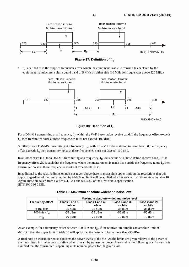
ETSI
ETSI TR 102 300-3 V1.2.1 (2002-01)60
375 380 385 390 395 400
F u F rb F rb
Base Station receive Mobile transmit band
Base Station transmit Mobile receive band
FREQUENCY (MHz)
Figure 37: Definition of frb
• fx is defined as is the range of frequencies over which the equipment is able to transmit (as declared by the
equipment manufacturer) plus a guard band of 5 MHz on either side (10 MHz for frequencies above 520 MHz).
Base Station receiveMobile transmit band
Base Station transmitMobile receive band
375 380 385 390 395 400
FREQUENCY (MHz)
Fx
5M5M HzHz Fd
Figure 38: Definition of fx
For a DM-MS transmitting at a frequency, fU, within the V+D base station receive band, if the frequency offset exceeds
frb then transmitter noise at these frequencies must not exceed -100 dBc.
Similarly, for a DM-MS transmitting at a frequency, Fd, within the V + D base station transmit band, if the frequency
offset exceeds frb then transmitter noise at these frequencies must not exceed -100 dBc.
In all other cases (i.e. for a DM-MS transmitting at a frequency, fU, outside the V+D base station receive band), if the
frequency offset, ∆f, is such that the frequency where the measurement is made lies outside the frequency range fx, then transmitter noise at these frequencies must not exceed -100 dBc.
In additional to the relative limits on noise as given above there is an absolute upper limit on the restrictions that will apply. Regardless of the limits implied by table 9, no limit will be applied which is stricter than those given in table 10. Again, these are taken from clauses 6.4.3.2.1 and 6.4.3.3.2 of the DMO radio specification (ETS 300 396-2 [2]).
Table 10: Maximum absolute wideband noise level
Maximum absolute wideband noise level Frequency offset Class 5 and 5L
mobile Class 4 and 4L
mobile Class 3 and 3L
mobile Class 2 and 2L
mobile < 100 kHz -36 dBm -36 dBm -36 dBm -36 dBm
100 kHz - frb -55 dBm -55 dBm -55 dBm -55 dBm
> frb -70 dBm -70 dBm -70 dBm -70 dBm
As an example, for a frequency offset between 100 kHz and frb, if the relative limit implies an absolute limit of -60 dBm then the upper limit in table 10 will apply, i.e. the noise will be no more than -55 dBm.
A final note on transmitter noise concerns the power levels of the MS. As the limits are given relative to the power of the transmitter, it is necessary to define what is meant by transmitter power. Here and in the following calculations, it is assumed that the transmitter is operating at its nominal power for the given class.

ETSI
ETSI TR 102 300-3 V1.2.1 (2002-01)61
10.3 Blocking Blocking is caused by a strong signal in an adjacent frequency to the required frequency. The presence of such a signal causes noise on the receiver local oscillator signal to be mixed on to the wanted signal. Note that it is assumed in our model (described below) that there is a linear relationship between the signal level and the noise produced. This implies that the receiver has a very large dynamic range. These assumptions of linearity and dynamic range are examined in clause C.3.
Blocking performance is specified in clause 6.5.1.2 of the DMO radio specification (ETS 300 396-2 [2]). This is in terms of the level of interfering signal in an adjacent channel that will produce a 3 dB increase in noise in the wanted channel. These are reproduced in table 11.
Table 11: Blocking levels of the receiver
Frequency Offset Level of blocking signal 50 kHz to 100 kHz -45 dBm
100 kHz to 200 kHz -40 dBm 200 kHz to 500 kHz -35 dBm
> 500 kHz -30 dBm
If the level of the adjacent signal exceeds that given above, then it is assumed that the noise produced also increases linearly.
10.4 Effects of transmitter noise and blocking Unwanted wideband transmitter noise and blocking signals both produce noise in the receiver on the wanted channel so the wanted signal must increase in power to compensate and maintain the required signal-to-noise ratio for successful reception. This has the effect, as far as the user is concerned, of reducing the range of the receiver since signals at the maximum range are those just above the noise floor. Thus increasing the noise drowns out these wanted signals and the effective range is reduced.
One attempt to quantify the effect of the interference would therefore be to calculate the reduced effective range of the receiver depending on the location and class of the unwanted transmitter.
However, from a user perspective, the reduction in range is not an immediately noticeable effect. All the user perceives is whether or not they can make or receive a call. Therefore, a more practical calculation is to determine the "exclusion zone" or "stay-away" distance required between the receiver and the unwanted transmitter for the wanted signal to be received.
A methodology to calculate this distance, based on the required path-loss, is given in clause 10.5.
10.5 Methodology This clause gives a general methodology for calculating the effect of transmitter noise and blocking on a given receiver. The following clauses give several worked examples and also discuss the implications of the effects of transmitter noise and blocking.
For a given wanted signal, what is required is the acceptable level of unwanted transmission noise and blocking. As the effects of unwanted transmitter noise and blocking decrease with separation (due to increased path loss between the receiver and transmitter) there will be some distance where the effects on the receiver will be below the critical level needed to disrupt communications. The methodology presented here allows the user to calculate that critical distance.

ETSI
ETSI TR 102 300-3 V1.2.1 (2002-01)62
Figure 39: Stay-away distance between interferer and victim receiver
The following terms are defined:
unwanted transmitter the transmitter responsible for generating the unwanted transmitter noise and the blocking;
victim receiver the receiver for which the critical distance is being calculated;
wanted signal the signal which the victim receiver is trying to receive.
The following general symbols are also defined:
fU the frequency at which the unwanted transmitter is transmitting (unwanted signal);
fW the frequency of the wanted signal being received by the victim receiver;
∆f the frequency offset between the wanted and unwanted signal (= |fW - fU|); C the power class of the unwanted transmitter; PC the power of the unwanted transmitter in dBm at the transmitter output socket;
NF the noise floor of the receiver in dBm;
NU the uplift in the allowed noise floor of the receiver in dB; L the total path loss experienced between the victim receiver and the unwanted transmitter in dB; LA the additional path loss due to antenna gains and body loss, etc, experienced between the victim
receiver and the unwanted transmitter in dB.
The following symbols are defined for calculating the effect of unwanted transmitter noise:
PNR the allowed unwanted transmitter noise relative to the transmitter power in dBc;
PNA the absolute level of allowed unwanted transmitter noise in dBm;
LN the required path loss such that transmitter noise has negligible effect on the unwanted signal in dB;
dN the stay-away distance such that transmitter noise has negligible effect on the unwanted signal in metres.
The following symbols are defined for calculating the effect of blocking:
PB the allowed level of blocking signal in dBm;
LB the required path loss such that blocking has negligible effect on the unwanted signal in dB;
dB the stay-away distance such that blocking has negligible effect on the unwanted signal in metres.

ETSI
ETSI TR 102 300-3 V1.2.1 (2002-01)63
10.5.1 Assumptions
The following assumptions have been made:
• the noise floor of the receiver, NF, is -122 dBm;
• the additional path loss, LA, is 14 dB (made up of 7dB body loss per MS and assumed isotropic antennas).
Note that these two assumptions hold only for mobile stations. In particular, the noise floor of the receiver is different for a base station, which is more sensitive. Therefore, it is recommended that for a base station the noise floor of the receiver, NF, is assumed to be -125 dBm.
10.5.2 Calculating the effect of transmitter noise
Assume that the unwanted transmitter is of power class C and that the frequency offset between it and the victim receiver is ∆f. From table 9, the allowed noise, PNR, can be determined. The maximum absolute noise level, PNA, is then:
P P PNA C NR= + (1)
If this is less than the absolute level given in table 10, then it shall be replaced with the level given in table 9.
If this absolute level of noise is greater than the noise floor of the receiver, NF, then the wanted signal will be affected by the noise. Therefore, to reduce the noise incident on the receiver, there will need to be a total path loss, L, of:
L P N L LNA F A N= − = + (2)
where the total path loss is made up of the loss due to the separation of the victim receiver and the unwanted transmitter, LN, and the loss due to other effects, LA. Therefore, rearranging equation (2), the required path loss is given by:
L P N LN NA F A= − − (3)
10.5.3 Calculating the effect of blocking
Assume that the unwanted transmitter is of power class C and that the frequency offset between it and the victim receiver is ∆f. From table 11, the allowed signal level at which blocking occurs, PB, can be determined. If this incident
signal from the transmitter, PC, is greater than this at the victim receiver, then blocking will occur. Therefore, to reduce the signal incident on the receiver, there will need to be a total path loss, L, of:
L P P L LC B B A= − = + (4)
where the total path loss is made up of the loss due to the separation of the victim receiver and the unwanted transmitter, LB, and the loss due to other effects, LA. Therefore, rearranging equation (4), the required path loss is given by:
L P P LB C B A= − − (5)
10.5.4 Allowing for a noise floor uplift
The above methodology assumes that the wanted signal is at the maximum range permissible, i.e. it is just above the noise floor and any additional noise will cause that signal to be indecipherable.
However, it is often the case that wanted signal will be transmitted from much closer than the maximum permissible range and therefore will be significantly above the noise floor. This can be allowed for in the above methodology by introducing a noise floor uplift.
The reference threshold defined by the TETRA standard is 19 dB above the receiver noise floor. Therefore, with a noise floor of -122 dBm, a signal of -103 dB will be the minimum that is capable of being received. However, if the signal is, for example, 39 dB above the noise floor, then an additional 20 dB of noise can be introduced and the signal will still be capable of being received. This 20 dB is the noise floor uplift, NU.

ETSI
ETSI TR 102 300-3 V1.2.1 (2002-01)64
When calculating the effect of unwanted transmitter noise, the noise floor uplift can simply be added to the noise floor. Thus equation (3) becomes:
( )L P N N LN NA F U A= − + − (6)
For blocking, the effect is similar. As blocking induces noise in the receiver, if the wanted signal is uplifted above the noise floor by an amount equal to the noise floor uplift, then the allowed level of interfering signal can also be uplifted by a similar amount (provided that the response of the receiver to blocking is linear). Thus equation (5) becomes:
( )L P P N LB C B U A= − + − (7)
10.5.5 Translating path losses into distances
The conversion of path loss into the physical distance separating the victim receiver and unwanted transmitter requires a knowledge of the local propagation conditions. The TETRA Designers Guide Part 1 [8] uses the Hata model which is valid for separations of over one kilometre. However, for the vast majority of circumstances of interest here, the path losses will equate to separations of less than a kilometre.
While the user should use whichever model best suits their local propagation conditions, for the purposes of the worked examples and discussion given here, the Bacon model will be used (see clause B.3).
The Bacon model is shown graphically in figure 40 for antennae heights of 1,5 m and 2 m at a frequency of 400 MHz, along with the path loss in free space and the path loss given by the CEPT SE21 model.
25
45
65
85
105
125
145
0 200 400 600 800 1000
Dis tance (m )
Pa
th L
os
s (
dB
)
Free Space Bacon CEPT SE21
Figure 40: Characteristics of the short range propagation models

ETSI
ETSI TR 102 300-3 V1.2.1 (2002-01)65
As can be seen, the Bacon model is a fairly conservative model, giving more loss than in the free-space scenario, but not as much the CEPT SE21 model. However, it must be stressed that the Bacon model has been chosen purely for illustrative purposes and users must determine which propagation model best suites their own local propagation conditions. In particular, the Bacon model was developed for an open, flat area and is not suitable for built-up areas.
A full discussion of the three models is given in annex B.
10.6 Example 1 - wanted signal at extremity of range, unwanted interferer close by
Consider a Class 4 transmitter (1 w power at the output socket) with a transmit frequency 125 kHz away from the victim receiver. What is the required path loss and stay-away distance in order that the victim receiver can still receive a wanted signal at its maximum range?
10.6.1 Step 1 - Calculate allowable noise
A Class 4 transmitter produces a signal of PC = +30 dBm. For a frequency separation of 125 kHz, table 9 gives a
maximum wideband noise level of PNR = -75 dBc. Substituting into equation (1), this gives an absolute noise level of:
dBm 45)75(30 −=−+=NAP
As this is a less stringent requirement than that given in table 10 (which is -55 dBm for a frequency separation of 125 kHz), it can be assumed that the unwanted transmitter will produce -45 dBm of noise.
10.6.2 Step 2 - Translate allowable noise into path loss and stay-away distance
Assuming a noise floor of NF = -122 dBm, other losses of LA = 14 dB and a noise floor uplift of NU = 0 dB (as the
received signal is at the maximum range), substituting into equation (6) gives a required path loss due to noise, LN, of:
dB 6314)0122(45 =−+−−−=NL
Using the Bacon model, this equates to a stay-away distance of 60 m.
10.6.3 Step 3 - Calculate path loss and stay-away distance for blocking
A Class 4 transmitter produces a signal of PC = +30 dBm. For a frequency separation of 125 kHz, table 11 gives a
maximum blocking signal of PB = -40 dBm. Substituting into equation (4), this gives a required path loss of:
dB 70)40(30 =−−=L
Assuming other losses of LA = 14 dB and a noise floor uplift of NU = 0 dB (as the received signal is at the maximum
range), substituting into equation (7) gives a required path loss due to blocking, LB, of:
dB 5614)040(30 =−+−−=BL
Using the Bacon model, this is equivalent to a stay-away distance of 36,5 m.
Therefore the limiting case is unwanted transmitter noise, which requires unwanted transmitters to remain 60 m or more away from the victim receiver.
This first example shows that if the wanted signal is at the limit of range then the unwanted interferer must stay some considerable distance away from the victim receiver to have negligible effect. We will show in the next example that if the wanted signal is not at the limit of range then the victim receiver is much more tolerant of interferers.

ETSI
ETSI TR 102 300-3 V1.2.1 (2002-01)66
The first example above relates to an operational scenario in which the victim receiver is at range limit corresponding to a widely distributed DMO group, to a trunked mode receiver in communication with a distant base station, to a DMO/TMO gateway in communication with a distant trunked mode BS or to a dual watch DMO terminal listening to a trunked BS (for messages addressed to it).
The following example corresponds to a number of DMO terminals working in close proximity such as independent operational groups attending the same incident.
10.7 Example 2 - wanted signal at close range, unwanted interferer close by
Consider a Class 3 transmitter (3 watts) with a transmit frequency 225 kHz away from the victim receiver. What is the required path loss and stay-away distance in order that the victim receiver can still receive a wanted signal being broadcast from 300 m away by a Class 4 transmitter?
10.7.1 Step 1 - Calculate noise floor uplift
In this example, the receiver noise floor does not limit the performance of the receiver. The Class 4 transmitter produces a signal of PC = +30 dBm, which is attenuated by a path loss caused by a separation of 300 m. The Bacon model gives a
path loss of 90 dB. It is assumed that the wanted signal also suffers further losses of 14 dB. Therefore the signal incident on the receiver, PW, is given by:
dBm 74149030 −=−−=WP
Allowing that this signal has to be 19 dB above the noise floor, this gives an effective noise floor of -93 dBm, which is 29 dB above the receiver noise floor. Therefore the noise floor uplift, NU, is 29 dB.
10.7.2 Step 2 - Calculate allowable noise
A Class 3 transmitter produces a signal of PC = +35 dBm. For a frequency separation of 225 kHz, table 9 gives a
maximum wideband noise level of PNR = -78 dBc. Substituting into equation (1), this gives an absolute noise level of:
dBm 43)78(35 −=−+=NAP
As this is a less stringent requirement than that given in table 9 (which is -55 dBm for a frequency separation of 225 kHz), it can be assumed that the unwanted transmitter will produce -43 dBm of noise.
10.7.3 Step 3 - Translate allowable noise into path loss and stay-away distance
Assuming a noise floor of NF = -122 dBm, other losses of LA = 14 dB and a noise floor uplift of NU = 29 dB (see
step 1), substituting into equation (6) gives a required path loss due to noise, LN, of:
dB 3614)29122(43 =−+−−−=NL
Using the Bacon model, this equates to a stay-away distance of 5,1 m.
10.7.4 Step 4 - Calculate path loss and stay-away distance for blocking
A Class 4 transmitter produces a signal of PC = +35 dBm. For a frequency separation of 225 kHz, table 10 gives a
maximum blocking signal of PB = -35 dBm. Substituting into equation (4), this gives a required path loss of:
dB 70)35(35 =−−=L

ETSI
ETSI TR 102 300-3 V1.2.1 (2002-01)67
Assuming other losses of LA = 14 dB and a noise floor uplift of NU = 29 dB (as in step 1), substituting into equation (7)
gives a required path loss due to blocking, LB, of:
dB 2714)2935(35 =−+−−=BL
Using the Bacon model, this equates to a stay-away distance of 1,8 m.
Therefore the limiting case is again unwanted transmitter noise, which requires unwanted transmitters to remain 5,1 m or more away from the victim receiver.
In contrast to the victim receiver in contact with a distant transmitter (such as trunked mode base station for trunked mode terminals, DMO gateways or dual watch DMO terminals) it will be seen that a number of DMO groups working in close proximity to each other are tolerant of the blocking and transmitter noise they impose on each other.
10.8 Unwanted transmission noise versus blocking The two worked examples above have shown that the transmitter noise dominates over blocking in both cases. It is worth noting that this is the general case for all frequency separations and for all classes of MS. This is illustrated for a Class 4 transmitter in figure 41, which shows the required path loss for a victim receiver receiving a signal at maximum range for frequency separations from 50 kHz to 600 kHz.
It can be seen that in all cases, the path loss for unwanted noise is greater than that for blocking.
30
35
40
45
50
55
60
65
70
75
50 150 250 350 450 550
Frequency Separation (kHz)
Req
uir
ed P
ath
Lo
ss (
dB
)
Transmitter noise path loss Blocking path loss
Figure 41: Path loss to reduce blocking Tx or wideband Tx interferer to negligible level
This path loss result can be translated into stay-away distances using the Bacon model as shown in figure 42.

ETSI
ETSI TR 102 300-3 V1.2.1 (2002-01)68
0.0
20.0
40.0
60.0
80.0
100.0
120.0
50 150 250 350 450 550
Frequency Separation (kHz)
Sta
y-aw
ay D
ista
nce
(m
)
Transmitter Noise Blocking
Figure 42: Stay away distance to ensure effects of blocking Tx or wideband Tx interferer are at negligible level
10.9 Variation of stay-away distance with transmitter power and frequency separation
The main variables in determining the stay-away distance, apart from the short range propagation model used, are the power of the unwanted transmitter and the frequency separation between the wanted and unwanted signals. This is illustrated in figure 43 for class 2, 3, 4 and 5 MSs with frequency separations from 50 kHz to 600 kHz.
0.0
20.0
40.0
60.0
80.0
100.0
120.0
50 100 150 200 250 300 350 400 450 500 550 600
Frequency Separation (kHz)
Sta
y-aw
ay d
ista
nce
(m
)
5
4
3
2
Figure 43: Stay away distance to ensure effects of blocking Tx or wideband Tx interferer are at negligible level for different interfering Tx power classes

ETSI
ETSI TR 102 300-3 V1.2.1 (2002-01)69
As can be seen, the effects increase with increasing class of MS (i.e. with increasing MS power) and decrease with increasing frequency separation. Note that the stay-away distances given here are for the unwanted transmitter noise case (as this is always the limiting case) and assume that the victim receiver is at the maximum range to receive the wanted signal. Therefore, these are the worst case stay-away distances.
Note also that the graphs are step functions rather than smooth curves. This is because they are based on the maximum permissible unwanted noise emitted by the unwanted transmitter in any given band. In reality, the transmitter noise is likely to be lower than the maximum permissible in the band as the frequency separation increases. However, without real data from real transmitters, this cannot be modelled here.
10.10 Effect of assumptions One of the main assumptions made here has been that of receiver linearity, which impacts on the levels of blocking experienced by the receiver. Providing that the receiver maintains linearity across its whole input range, then the calculations are valid. However, if the receiver exhibits non-linear behaviour, then the levels of blocking experienced at high signal strengths may well have been underestimated.
The main assumption given here is the amount of attenuation and other path losses represented by the term LA. This includes antenna losses and body losses. However, the loss produced by the human body is highly anisotropic and cannot be accurately defined by a single figure. Although a single figure has been used by necessity in these worked examples, in real scenarios the value of the term LA will depend on the circumstances.
For example, the loss provided by human body absorption is going to be significantly different if the body in question is between the receiver and the transmitter or if the receiver has a clear line of sight to the transmitter. Therefore, provided that the wanted transmitter and the unwanted transmitter are not in the same direction, considerable extra protection can be provided by judicious positioning of the users' body.
Similarly, if the victim receiver is not a hand-held MS (e.g. a vehicle mounted MS) then the assumption of an additional loss term of LA = 14 dB may well no longer hold.
It should be realized that for distances greater than about 30 m the choice of short range propagation model had a significant effect. All calculations have been performed with the Bacon model which is intermediate between the highly attenuating SE21 model (which allows MSs to work close together) and the free space model (which has lower attenuation and requires larger stay-away distance).
Finally, the assumed noise floor of the receiver will depend on whether the receiver is a mobile station or a base station, since under the TETRA specification, MS and base stations have different reference sensitivities. The assumption made for the calculations given here is that the receiver is a mobile station in all cases.
10.11 Implementation issues One of the main issues facing DMO system designers is whether to place the direct mode band in the trunked mode base station transmit band or in the base station receive band.
This clause discusses the various consequences associated with this decision, including the differing effects of the choice of band on the end user and the probability that, due to synchronization between direct and trunked mode operation, transmissions will take place in different time slots.
The effects presented here apply equally to direct mode and trunked mode receivers. However, there are some differences, depending on whether the receiver in question is a base station or an MS, which in turn will influence whether the system designer places the direct mode carrier frequencies in the trunked mode base station transmit band or in the base station receive band.
Figure 44 is a diagram of the situation when the direct mode frequencies are placed in the base station transmit band.
Practical experience and user preference (see annex G) suggests that DM-MS transmit in TMO BS transmit band should reduce the interference of DMO to the TMO network. This should reduce the effects of interference to the largest number of TMO users by avoiding TMO BS receiver blocking.

ETSI
ETSI TR 102 300-3 V1.2.1 (2002-01)70
CROW N
Band 1: Trunked mode BS receive band Band 2: Trunked mode BS transmit band
Figure 44: DM frequencies in TM-BS transmit band
TM-MS TxTM-BS Rx
TM-MS RxTM-BS Tx
DM-MS TxDM-MSRx
Band 1 Band 2
Frequency
Figure 45: Frequencies with DM MS-MS call in trunked mode downlink band
If the direct mode frequencies are placed in the base station transmit band (as shown in figure 45), this means that the trunked mode base station and the direct mode MSs are both transmitting close to same frequency. The following problems could therefore occur:
• direct mode MSs could suffer effects from trunked mode base station transmissions;
• direct mode MS transmissions could cause problems to trunked mode MSs.
As stated above this is the preferred configuration since trunked mode operation will be least affected if direct mode MS operates close to a base station.
Figure 46 is a diagram of the alternative situation when the direct mode MS-MS frequencies are placed in the base station receive band. This configuration should be used with care since the DM MSs, if allowed to operate close to the trunked mode BS, may cause severe desensitization.

ETSI
ETSI TR 102 300-3 V1.2.1 (2002-01)71
CROW N
Band 1: Trunked mode BS receive bandBand 2: Trunked mode BS transmit band
Figure 46: DM frequencies in TM-BS receive band
TM-MS TxTM-BS Rx
TM-MS RxTM-BS Tx
DM-MS TxDM-MS Rx
Band 1 Band 2
Frequency
Figure 47: Frequencies with DM MS-MS call in trunked mode uplink band
If the direct mode frequencies are placed in the base station receive band (as shown in figures 46 and 47), this means that both the trunked mode and direct mode MSs are transmitting close to the same frequencies. The following problems could therefore occur:
• direct mode MSs could suffer blocking and desensitization from trunked mode MS transmissions;
• direct mode MS transmissions could cause problems for trunked mode base stations.
When considering the effects suffered by direct mode MSs, it can be seen that these are very different in figures 44 and 46. In the first case, direct mode MSs will only be affected by base stations. As stated previously DM-MSs working in close proximity to each other (i.e. not range limited) are tolerant of other interfering transmitters. Furthermore, in many operational scenarios, direct mode may be used to extend the range of users who will, by definition, be operating around the margins of trunked mode coverage and therefore unlikely to be affected by base station transmissions.

ETSI
ETSI TR 102 300-3 V1.2.1 (2002-01)72
In the second case, direct mode MSs could suffer effects from trunked mode MSs operating in the same physical area. In many operational scenarios, trunked mode and direct mode MSs will be deployed in the same physical location, which could lead to operational difficulties.
When considering the effect caused by direct mode MSs, it can be seen that these are also very different. In the first case, the presence of direct mode MSs could lead to problems for trunked mode MS users, while in the second case, the presence of direct mode MSs could lead to problems for the trunked mode base station.
While both of these will have consequences for users, effectively reducing the range of nearby trunked mode MSs will probably affect one or two users, while reducing the range of a base station could potentially affect many users on that base station, which would be a more serious problem.
It is possible to calculate the stay-away distance for the DM MS from the trunked mode BS using the methodology established in clause 10. However the vertical directivity in the trunked mode BS (i.e. effective attenuation close-in) needs to be taken into effect if accurate results are to be obtained. Order of magnitude figures for stay-away distances are discussed in clause 8.7.9.
The restrictions caused by the choice of band are summarized in table 12, along with the equipment affected if the restrictions are not maintained.
Table 12: Service Restrictions and equipment affected by choice of DMO operating band
Scenario Restriction Equipment affected DMO band in TM base station transmit band
1. Stay-away zone between DMO MSs and TM MSs
1. TM MSs
2. Stay-away zone around TM base stations for DMO MSs
2. DMO MSs
DMO band in TM base station receive band
1. Stay-away zone between DMO MSs and TM MSs
1. DMO MSs
2. Stay-away zone around TM base stations for DMO MSs
2. TM base stations
10.12 Recommended frequency separation for DMO MS-MSs The methodology defined in clause 10.5 for calculating the stay away distance for an interfering transmitter from a victim receiver has been used to compare calculated and measured results. This is documented in annex C.
Field trials carried out in the course of this validation exercise based on a wanted signal from a transmitter up to 500 m distant (i.e. not noise limited) and taking into account non-linear blocking indicated that if a 5 m stay-away distance is to be achieved then:
• in rural areas a frequency separation of 50 kHz (between wanted and unwanted signals) is required;
• in urban areas a frequency separation of 100 kHz (between wanted and unwanted signals) is required.
11 Operational scenarios
11.1 Range extension scenario using type 1A repeater A Communications Officer responsible for facilitating communications on behalf of professional users such as the Emergency Services or a commercial organization has the job of planning for operational scenarios that staff will encounter in the course of their duties. This clause describes how a direct mode repeater could be used to define the range of DM MSs in critical operational scenarios such as at a road traffic accident, or a major fire.
DM MSs could be deployed (or more likely DM operation selected on the handheld MS control) because trunked mode radio coverage is not available at the incident, for example, if the incident is in a rural area with no coverage, or if it is in a building with no in-building hand-held radio coverage. DM MSs could be deployed with no repeater, but then the communications coverage would not be well defined because coverage would be different for each transmitting MS.

ETSI
ETSI TR 102 300-3 V1.2.1 (2002-01)73
Indeed, MSs at opposite ends of the incident might not be within range of each other. Deploying a repeater at the centre of the incident will ensure that all MSs within range of the repeater can reliably communicate with each other.
In advance of the incident operational and contingency planning would need to have been done to ensure that the users could begin communicating with each other as soon as they arrived at the incident. This preparation requires the selection and installation of the appropriate options for both the MSs and the repeater. The MS options are:
• DM only or TM radio with DM capability. Since there may be no TM coverage either of these options may be selected.
• MS to MS only or repeater capable. For full flexibility the repeater capable option must be selected.
The repeater options are:
• Choice of repeater type 1A or 1B or 2. These are all physically different with different co-existence characteristics as describes in clause 8.7. Type 1A supports one call on one frequency, type 1B supports one call on two frequencies and type 2 supports two calls on two frequencies. For this scenario we will assume we are outside TM coverage and type 1A has been chosen.
• Repeater presence signal. The repeater sends this signal during calls, but can also optionally send it when it detects that the channel is free in order to indicate its presence to the MSs. Whether or not this option is selected will depend on the group's operational procedures. See below for more detail.
• Usage restriction type. This determines which MSs may use the repeater. The options are no restriction (open), restricted by prior arrangement, restricted to a single MNI, or restricted to a single TSI. Which option is selected will depend on the group's operational procedures.
In common with MS-MS scenarios the usual mobile station parameters must be pre-defined:
• which operational frequency(channel) to select;
• which group identity (GTSI);
• which static cipher key (SCK).
Having selected the above options, the MSs and repeater are now ready to be deployed. Let us assume that some of the MSs arrive at the incident before the repeater, and that they will need to begin communicating immediately. Then at various intervals the repeater and the rest of the MSs will arrive, and that when the repeater arrives, the MSs will be required to make their calls through it. The operation should be planned as follows:
a) The first MSs to arrive at the incident should be instructed to begin communicating amongst themselves using DM MS-MS normal mode (because frequency efficient mode is not valid for operation with a type 1 repeater). They will have been organized in one or more talkgroups on the same channel. The receiving MSs (the slaves) will synchronize to the transmitting MS (the master). The protocols are described in clause 8.4.1 (outline) and clause E.2 (detailed).
b) More MSs will arrive, and will monitor talk groups on the designated channel. If the channel is free they can either listen for the next call or initiate one. If a call is in progress, they can join it using the late entry protocol described in clause E.2.6.
c) The repeater arrives. This is where the presence signal option applies because it will determine how the MSs switch to repeater operation:
i) If it was planned for the incident commander, using his MS in MS-MS normal mode, to instruct the MSs when to begin using the repeater, then it is not necessary for the repeater to send its presence signal when the channel is free. Note that if there is more than one group he may need to instruct each group separately. MSs arriving after the repeater will only know that the repeater is operating by monitoring the channel. However, if a MS initiates a call in MS-MS normal mode while a type 1A repeater is operational, it will still be received by all MSs in its talkgroup that are within range, but the standard does not define whether or not they will accept the call. Hence it is preferable to configure the repeater to send its presence signal when the channel is free.

ETSI
ETSI TR 102 300-3 V1.2.1 (2002-01)74
ii) If it is necessary for the MSs to start using the repeater as soon as it becomes available, then the repeater should be configured to send its presence signal when the channel is free. Then MSs arriving at the incident will always know if the repeater is operational. The incident commander will still be able to control when the MSs switch to repeater mode by powering the repeater up.
iii) How the MSs switch from MS-MS normal to repeater mode is not defined in the standard. It will be determined by the manufacturer with user input. It could be carried out manually by the user, or automatically by the user application (on detection of valid repeater presence signal).
d) Range effects:
iv) Single carrier. Without a repeater a group of DM MSs can communicate, but the range will vary depending on the locations of the transmitting MS and the receiving MSs. This means that MSs near the centre of the incident have a better chance of communicating with the whole group than MSs near the edge. Deploying a repeater near the centre of the incident or on local high ground stabilizes the range, because any MS which can communicate with the repeater can communicate with all the MSs within range of the repeater.
v) The range over which the MSs can communicate with each other will also be extended. With no repeater, the diameter of the group is limited to the MS to MS range, but with a repeater at the centre or in a location with height gain in the area of DM operation, the MS to MS range becomes the radius of the group. To a first approximation this would quadruple the area over which the group would have reliable communication, but could be less than this because every transmission path now has two legs. This reduction is minimized because the repeater de-encodes and re-encodes the MS transmissions before forwarding them, which improves the bit error performance. The reduction could also be more than offset by the location of the probably more efficient repeater antenna.
(vi) Two or more carriers in the same band. There may need to be several groups at the incident, using more than one frequency to avoid congestion delaying calls, or the groups may have already been allocated different frequencies. If possible frequencies should be chosen that are far apart from each other (see note), but there may be no choice, and the closer they are, the more interference they can cause each other. Refer to clause 10, Radio Aspects for the details. Interference will most likely be caused by the radios transmitting noise in their neighbouring channels. This noise can desensitize any receivers that are close to the transmitter and so reduce their range. Clause 10 shows you how to calculate stay away distances, which depend on frequency and physical separation. The location of the repeaters is critical. They should be no closer than their stay away distance, but not much further, and the plan should be for the MS users on different frequencies to keep as far away from the repeater and MSs on other frequencies as is practical.
NOTE: Frequency separation greater than 50 kHz in rural areas or greater than 100 kHz in urban areas for a 5 m stay-away distance. See clause C.10 for justification.
e) Communications for the incident are now operational through the repeater. Calls can now proceed using the protocols in clause E.3.
f) When the incident is over, some MSs may remain at the scene, for example to clear up, but the repeater may need to be re-deployed. In this case, there should be a procedure for the remaining MSs to revert to MS-MS normal mode.
11.2 Range extension scenarios using a gateway A direct mode gateway (DM-GATE) can be used to extend trunked mode radio coverage, thus allowing users to keep in touch with their dispatchers and other members of their group. A typical scenario would be a DM gateway fitted to a vehicle, allowing a user with a handheld (HH) terminal to keep in radio contact when they leave their vehicle. In this clause a number of closely related scenarios will be examined, corresponding to:
• Gateway with no infrastructure support; single user.
• Gateway with no infrastructure support; multiple users.
• Gateway with infrastructure support; single or multiple users.
In all of these scenarios the functionality encountered will closely depend on the implementation approach taken by the infrastructure manufacturers. The examples outlined below should only be taken as typical (not definitive) and clarification sought from equipment suppliers on points of detail.

ETSI
ETSI TR 102 300-3 V1.2.1 (2002-01)75
In early implementations there is likely to be very simple switched infrastructure capability, explicitly without the message exchanges needed to register multiple DM users behind a gateway. However there will still be useful functionality provided by a gateway in such circumstances. This will be outlined below.
a) No infrastructure support for gateway operation: single user
Since in this example there is no explicit gateway signalling supported by the infrastructure the gateway acts just like any other trunked MS. Each gateway (MS) must select which group(s) to attach to the infrastructure. In this case it seems logical that the MS(s) on the DMO side of the gateway will be restricted to the same groups as the gateway. In infrastructures with different group attach arrangements the gateway may perform differently. Hence the basic trunked mode MS operation needs to be examined for the particular manufacturer implementation.
Now let us follow how a user may need to interface to the equipment. Consider a user in a vehicle with HH terminal. When the user leaves vehicle, wanting to stay in touch with their dispatcher, they must first select "gateway operation" on the vehicle mounted MS. Then the user must switch their HH terminal to "gateway operation". As in the previous example for Repeater Operation the basic MS parameters should already have been planned and enabled in the terminals by their communications officer; namely operational frequency (channels) and group identity to use. Similarly the gateway should have the requisite parameters planned and enabled, namely the frequency and group ID it can support on the DM side, any user restrictions that will be invoked, whether a presence signal will be transmitted. This same information needs to be in the DM MS so that it will know how to respond when it encounters a gateway at an incident.
With a single user implementation any individual calls through the gateway can be relayed straight to the HH terminal.
In our example the vehicle mounted gateway transmits its presence signalling. The HH synchronizes with the gateway and listens for communications from the infrastructure. The HH can also initiate individual calls into the infrastructure via the gateway.
b) No infrastructure support for gateway operation: multiple users in the DM group
This is an extension to the previous implementation, still based on the restricted infrastructure implementation. Even if we consider that the gateway MS is not limited to a single group but can send and receive control signalling for several groups it seems clear that the gateway and DMO HH must be members of the same group set.
Alternatively, the gateway may have pre-ordained (frequency) channel allocations but be capable of performing a proprietary number (GTSI to GTSI) translation between the trunked and DM side of the gateway. This arrangement will support interconnection between roaming national DMO/GTSI MSs who have a defined GTSI and local users performing similar functions on different GTSIs. The gateways will need to have the number translation coded in and the relevant numbers will need to be known in advance both by the gateway and the DM MSs.
Note that this gateway scenario would be appropriate for group operation inside a building (e.g. fire or police) where there is a need to keep the control room informed on activities. The gateway must be included in the call from the beginning, it can not be included after the call has been set up. As the operation proceeds deeper into the building there may be a point reached where the gateway loses contact with the transmitting MS. Whilst outside contact has now been lost the MSs are still able to communicate with each other without the need to clear down the call and set up an MS-MS call. This is in contrast to repeater and repeater/gateway operation for which the ongoing call would have to be cleared and a new call set up to re-establish contact with close-by MSs in the group.
c) With infrastructure support for gateway operation: single and multiple users
Full infrastructure support of gateway operation will allow individuals behind the DM gateway to register with the gateway and hence for calls individually addressed to them to be forwarded.
The air interface specification will allow any terminal to participate in any authorized protocol exchanges and any restrictions (such as a single group or sub-set of available groups) has been imposed by the manufacturer implementation. Whether similar restrictions will be imposed for gateways operating in a supported manner on advanced infrastructures has yet to be seen.

ETSI
ETSI TR 102 300-3 V1.2.1 (2002-01)76
The gateway should not to be a member of any particular group but simply monitor air interface signalling directed to one of the MSs or groups behind it. Therefore the DM-MS should attach to the GTSIs of the trunked network via the DM-GATE following the procedures defined in ETS 300 396-5 [4].
At the time of release of the present document (Version 1.2.1) there was no mechanism defined for authenticating DM MSs through a gateway and hence they represent a potential threat to network security. That is not to say they have no security. Indeed they do but it relies on SCK static cipher keys in the DM net providing a secure communication to the gateway. The gateway itself can be rigorously authenticated to the infrastructure.
11.3 DMO range extension scenario with link into TMO Dispatcher using a type 1B repeater/gateway
This scenario, using a cliff rescue as an example, builds on the DMO range extension scenario in clause 11.1 and the gateway scenario described in clause 11.2. Note that in this scenario neither the repeater nor the gateway alone would satisfy the operational requirements. The repeater alone would not provide connectivity back to the trunked infrastructure. The gateway alone would not work (if all local MSs are to be in direct mode) because the DM users have no line of sight radio path between them. However if the cliff top local MSs are allowed to be in trunked mode and interconnected to the direct mode users at the foot of the cliff via the gateway then an airborne gateway would indeed satisfy the requirements. However let us consider a scenario where local trunked radio coverage to a handheld MS is not supported or the decision is made operationally not to use the local infrastructure, for instance if it is felt that the traffic load will be too large.
Consequently, the Communications Officer decides to deploy a DM-REP/GATE in a helicopter. Figure 48: Cliff rescue shows a representation of the scenario.
Figure 48: Cliff rescue using repeater/gateway

ETSI
ETSI TR 102 300-3 V1.2.1 (2002-01)77
In advance of the incident operational and contingency planning would need to have been done to ensure that the users could begin communicating with each other as soon as they arrived at the incident with the simplest operating procedures. To do this requires the selection and installation of the appropriate options for both the MSs and the repeater/gateway. The MS options are:
• DM only or TM radio with DM capability. Since there may be no TM coverage over part of the scenario (e.g. foot of cliff), either of these options may be selected.
• MS to MS only or repeater/gateway capable. The repeater/gateway capable option must be selected.
The repeater/gateway options are:
• Repeater/gateway type 1A or 1B. Type 1A supports one call on one frequency, while type 1B supports one call on two frequencies. Which type is chosen will depend on which types are allocated to the group, but for this scenario we will assume type 1B.
• Repeater/gateway presence signal. The repeater/gateway sends this signal during calls, but can also optionally send it when it detects that the channel is free in order to indicate its presence to the MSs. Whether or not this option is selected will depend on the group's operational procedures. See below for more detail.
• Usage restriction type. This determines which MSs may use the repeater. The options are no restriction (open), restricted by prior arrangement, restricted to a single MNI, restricted to a single TSI, or to one TSI and one SSI or to three SSIs. Which option is selected will depend on the group's operational procedures.
• TM frequencies. Normally a helicopter would use special air to ground sites and frequencies. This is to avoid interference to the to the normal TM system caused by the extended range of the helicopter at altitude. However, in this scenario, the helicopter could well be just above cliff top level, out of range of the air to ground sites and would need to use the nearest normal site and frequencies.
• DM frequencies. Direct MS to MS communications may take place on either the uplink or downlink DM-REP/GATE frequency. Whether or not this option is selected will depend on the group's operational procedures. See below for more detail.
As in clause 11.1, some of the MSs may arrive before the helicopter, and communicate in MS-MS normal mode, provided that they are not obscured from each other by the cliff. Later arrivals can monitor the channel and initiate a call or use late entry. However, when the helicopter arrives with a REP/GATE a changeover procedure needs to be adopted. How the MSs switch to repeater/gateway operation will depend on whether the MS to MS communications are on the DM-REP/GATE uplink or downlink frequency as well as whether or not the DM-REP/GATE transmits its presence signal on the free channel. This is because if the uplink frequency is used, the MSs will not detect the presence signal on the downlink frequency, so they will need to be told to switch by a call on the downlink frequency, preferably from the helicopter, since it has the best chance of seeing all the MSs. (The mobile users will probably hear the helicopter arriving, so this could be the signal in this scenario, but it might not work in other scenarios where the repeater/gateway is vehicle mounted). Conversely, if the downlink frequency is used for transmission, the repeater/gateway would preferably have the facility to monitor activity on its downlink frequency, so that it did not start transmitting its presence signal while a MS to MS call was taking place.
The remainder of clauses 11.1 and 11.2 apply.
11.4 DMO range extension scenario with link into TMO Dispatcher using a gateway
This scenario is very similar to the previous except that the operational decision has been made to use a gateway in the helicopter rather than the repeater/gateway. As a result of this choice it must be realized that the cliff top MS and the cliff foot MS can not communicate directly nor via the helicopter since in gateway operation communication is from the transmitting MS direct to the receiving MSs. Hence good TM coverage must be assured for the cliff top officer. TM coverage to the helicopter is unlikely to be a problem due to vehicle altitude, vehicle mounted equipment and connection (possibly) to a separate airborne vehicle trunked mode network.
The scenario connectivity is shown in figure 49.
In many ways this scenario is simpler than the REP-GATE solution but it does require that the cliff top MS is in good trunked mode radio coverage.

ETSI
ETSI TR 102 300-3 V1.2.1 (2002-01)78
Figure 49: Cliff rescue using airborne gateway
Gateway (only) functionality will be simpler for manufacturers to implement than the repeater/gateway combination so this scenario may find wider application than that described in clause 11.3.
11.5 Range extension inside buildings using a type 2 repeater This scenario uses a fire in a large building as an example. TM coverage is available outside the building, but not inside. The communications required are mainly between officers inside and just outside the building, with occasional calls to the TM infrastructure. Due to possible propagation difficulties caused by the building, the Communications Officer decides that a repeater should be deployed inside the building, and, because the situation may require more than one call to take place at a time, he decides to use a type 2 repeater which will allow two calls to take place simultaneously.
However, a type 2 repeater cannot be combined with a gateway to make a repeater/gateway, so it is decided to issue the officers with dual watch radios, so that any officer outside the building in TM coverage can make a call to the infrastructure when necessary. There is always the possibility that, even with the repeater deployed inside the building, an officer may reach a part of the building where his radio loses contact with the repeater. To cope with this eventuality, the radios are programmed with a separate DM frequency for normal direct mode MS to MS communication.
In advance of the incident operational and contingency planning is necessary to ensure that the users could begin communicating with each other as soon as they arrived at the incident with the simplest operating procedures. To do this requires the selection and installation of the appropriate options for both the MSs and the repeater. The MS options are:
• DM only or dual mode capable or dual watch capable. Dual watch should be selected. Since any officer engaged in a TM call will want to monitor the DM channels simultaneously, full dual watch should be implemented.
• MS to MS only or repeater capable. The repeater capable option must be selected.

ETSI
ETSI TR 102 300-3 V1.2.1 (2002-01)79
The repeater options are:
• Repeater type 2 is the only repeater which allows two simultaneous calls.
• Repeater presence signal. The repeater sends this signal during calls, but can also optionally send it when it detects that the channels are free in order to indicate its presence to the MSs. Whether or not this option is selected will depend on the group's operational procedures. See below for more detail.
• Usage restriction type. This determines which MSs may use the repeater. The options are no restriction (open), restricted by prior arrangement, restricted to a single MNI, restricted to a single TSI, or to one TSI and one SSI or to three SSIs. Which option is selected will depend on the group's operational procedures.
• DM frequencies. The repeater downlink frequency can either be in the TM downlink band or in the TM uplink band. See clauses 8.7.4 and 8.7.5 for more detail. The separate MS to MS frequency could also be in either band. See below for more detail.
In this scenario the repeater will arrive at the scene at the same time as the MSs, and all MSs will use it initially. If possible, the repeater will be taken inside the building to try and maximize in building coverage. The lead officer outside the building will be responsible for communications to the infrastructure using dual watch. Dual watch synchronization will have to be carefully managed. While channel A calls are initiated by dual watch radios still within TM coverage they will align the timing reference to the TM downlink, and channel B calls will be synchronized to channel A, so there will be no problem. However, if a MS inside the building and outside TM coverage initiates a channel A call, if not properly configured it could choose an arbitrary timing reference, and dual watch would no longer be possible. It is important, therefore, that MSs initiating channel A calls should be programmed to take their timing reference from the repeater presence signal, particularly if the presence signal dual watch synchronization flag is set to 1. It would also be good practice for MSs within TM coverage to initiate channel A calls fairly frequently to ensure that synchronization is maintained.
It will still be possible for there to be areas inside the building where there is no repeater coverage. If this happens, the officers should have been trained to switch their MSs to the direct MS-MS frequency. This, of course, relies on another MS in the vicinity also being switched, but it is assumed that officers in a hazardous area will always be within sight of at least one other officer, so some visible signal could be devised to signal the switch.

ETSI
ETSI TR 102 300-3 V1.2.1 (2002-01)80
Annex A: Teleservices, bearer and supplementary services supported by TMO/DMO
Table A.1: Comparison of Trunked and Direct mode tele, bearer and supplementary services
Service Trunked Mode Direct Mode Teleservices: Clear speech or encrypted speech in each of the following: Individual call (point-to-point) � �simplex only Group call (point-to-multipoint) � � Acknowledged group call �
Broadcast call (point-to-multipoint one way) � � Data bearer services: Circuit mode unprotected data 7,2, 14,4, 21,6, 28,8 kbit/s � 7,2 (single slot)
Circuit mode protected data 4,8, 9,6, 14,4, 19,2 kbit/s � 4,8 (single slot)
Circuit mode protected data 2,4, 4,8, 7,2, 9,6 kbit/s � 2,4 (single slot)
IP Packet data �
Short data service (type 1, 2, 3, 4) � � Status messages � � PMR type supplementary services: Access priority � Pre-emptive priority � � Priority call � Include call � Transfer of control � Late entry � � Call authorized by dispatcher � Ambience listening � Discreet listening � Gateway option only
Area selection � Short number addressing � Talking party identification � � Dynamic group number assignment � Telephone type supplementary services: List search call � p
Call forwarding – unconditional/busy/no reply/not reachable �
Call barring – incoming/outgoing calls �
Call report � p
Call waiting �
Call hold �
Calling/connected line identity presentation � p
Calling/connected line identity restriction �
Call completion to busy subscriber/on no reply � p
Advice of charge �
Call retention �
Application: OTAR (over the air re-keying) � � p = proprietary.

ETSI
ETSI TR 102 300-3 V1.2.1 (2002-01)81
Annex B: Short range propagation models used in the co-existence studies
B.1 Introduction This annex discusses three short range propagation models, all applicable for separations under a kilometre. The three models are:
• Free Space;
• Bacon;
• CEPT SE21.
Each model is discussed in turn in clauses B.2, B.3 and B.4.
B.2 Free space propagation The free space propagation model serves as a baseline model against which other models can be judged. It can also be derived from first principles, as described below.
Consider the ideal free space attenuation between separated antennas. If a transmitting antenna with gain GT in the
direction of the receiving antenna radiates PT Watts of power then the power density, W, (in units of power per unit area) at a distance d is given by:
24 d
GPW TT
π= (1)
The available power at the receive antenna with effective area A is therefore:
Ad
GPP TT
R ×=24π
(2)
Substituting for the effective area, A, gives:
π
λπ 44
2
2RTT
RG
d
GPP ×= (3)
and thus the ratio of received to transmitted power is:
2
4
=d
GGP
PTR
T
R
πλ
(4)
Using the fundamental relationship:
λ×= fc
where: c is the speed of light ( 8103× m/s); f is the operational frequency;
λ is the free space wavelength;

ETSI
ETSI TR 102 300-3 V1.2.1 (2002-01)82
and expressing the frequency units in MHz, distance in km, the path loss, L, in dB, can be written as:
kdfGG
P
PL
RT
T
R
+⋅−⋅−⋅+⋅=
⋅=
10101010
10
log20log20log10log10
log10 (5)
where:
.44,32104
103log20
9
8
10 −=
××⋅=
πk (6)
The basic path loss between isotropic antennas can thus be stated as:
32,44+log20+log20= 1010 dfL ⋅⋅ (7)
where f is in MHz and d is in km. For a frequency of 400 MHz, equation (7) reduces to:
32,44.+log20+52,0= 10dL ⋅ (8)
This is the path loss for ideal free space propagation at 400 MHz.
This is shown graphically in figures B.1, B.2 and B.3.
B.3 Bacon model The Bacon model was proposed in reference [11] and is designed for use in flat, open areas. The model incorporates antenna heights as well as the propagation frequency. The following variables are used:
f operational frequency (MHz); d separation between antenna (km); h1 antenna height at one end of path (m);
h2 antenna height at other end of path (m); p percentage of locations where signal is exceeded.
The Bacon model gives a basic transmission loss of:
( )2110log10 LL L +⋅= (9)
where:
( ) [ ]( )84,0100log2310101 1010log10log204,32 --p) ( - df L +⋅+⋅⋅+= ⋅ (10)
cm L LL +=2 . (11)
The term Lm is given by:
( )211010 log20log40120 hhd - Lm ⋅⋅⋅+= (12)
while the term Lc is a more complicated function given by:
( )( ) otherwise101.0
5.001.0
σσ
⋅−=>⋅=
pI
ppILc (13)
The standard deviation, σ, is defined as:
otherwise0
03.2
=
>= dd L
Lσ (14)

ETSI
ETSI TR 102 300-3 V1.2.1 (2002-01)83
where:
4,32log20 10 d) - (f - L L md ⋅⋅= . (15)
It is also necessary to calculate the minimum value of standard deviation:
5.0min 1.02 f+=σ (16)
and if σ < σmin then set σ = σmin.
The function I(x) in equation (13) is defined as:
( ) ( ) ( )xTxxI ⋅= ξ (17)
with T(x) defined as:
( )x- T(x) ln2 ⋅= (18)
and ξ(x) defined as:
)(
)()(
xB
xAx =ξ (19)
where:
[ ] 012 )()( CxTCxTCA(x) +⋅+⋅= (19a)
[ ]( ) 1)()()()( 345 +⋅+⋅+⋅= xTCxTCxTCxB (19b)
with:
C0 = 2,515516698
C1 = 0,802853
C2 = 0,010328
C3 = 1,432788
C4 = 0,189269
C5 = 0,001308
This is shown graphically in figures B.1, B.2 and B.3.
B.4 CEPT SE21 model The CEPT SE21 propagation model was proposed in ITU-R Recommendation SM.329-6 [10]. It is a three part model, which also incorporates the antenna heights as well as the propagation frequency.
The following variables are defined:
hmin height of smaller antenna;
hmax height of larger antenna;
d is the spacing between the antennas.
The three part CEPT SE21 model gives a path loss of:
32,44+log20+log20= 10101 dfL ⋅⋅ 0,04km≤d (20)
( ) ( ))04,0(log)1,0(log
(0,04))1,0(04,0log-log+(0,04)=
1010
13101012 −
−× LLdLL 0,1km0,04 <d< (21)

ETSI
ETSI TR 102 300-3 V1.2.1 (2002-01)84
( )[ ]( )[ ]( )
( ) ( )maxmin
10max10
max10103
,
log;30maxlog55,69,44
;30maxlog82,13log2,266,69
hbhfa
dh
hfL
−−×⋅−+
⋅−⋅+=
0,1km≥d (22)
where the constants a and b are given by:
( ) ( )
⋅−⋅×−⋅10
log0;20max+8,0log1,56-);10min(7,0log1,1= min1010min10
hfhfa
⋅30
log0;20min= max10
hb (23)
Looking at the model terms, it is clear that the CEPT SE21 model for separations under 40m (equation 20) is none other than the free space propagation model (equation 7). Equation (22), which applies to separations greater than 100 m, is quite a complex equation, but for a fixed frequency of 400 MHz and antenna heights of less than 30m, it reduces (see reference [12]) to:
)()(log5,22336,117 maxmin103 hbhadL −−+= (24)
which is similar to the free space propagation model (equation 7) except that the constants are significantly larger. The CEPT SE21 model for separations between 40 m and 100 m (equation 11) is simply a linear interpolation between the value of the model at 40 m and at 100 m.
This is shown graphically in figures B.1, B.2 and B.3.

ETSI
ETSI TR 102 300-3 V1.2.1 (2002-01)85
B.5 Discussion The three models are shown graphically in figure B.1. They have been calculated for a frequency of 400 MHz and the Bacon and CEPT SE21 models for antenna heights of 2 m and 1,5 m respectively. It is immediately clear that for small separations (50 m or less) the three models give similar results, but as the separation increases, so do the differences between the models, with the CEPT SE21 model giving by far the largest path loss, while the free space model gives much lower path losses.
25
45
65
85
105
125
145
0 200 400 600 800 1000
Dis tance (m )
Pa
th L
os
s (
dB
)
Free Space Bacon CEPT SE21
Figure B.1: Calculated path loss for the three propagation models h1 = 1,5m, h2 = 2m
Although figure B.1 is representative of the Free-Space model, the Bacon and CEPT SE21 models also have the antenna heights as model parameters. The antenna heights significantly affect the behaviour of the two models at separations over 100 m.
The antenna heights of 2 m and 1,5 m used in figure B.1 are representative of two hand portables. However, if one antenna is significantly higher than the other, then the path loss is reduced at large separations (approaching 1 km). This is illustrated in figure B.2 for antenna heights of 30 m and 1,5 m.

ETSI
ETSI TR 102 300-3 V1.2.1 (2002-01)86
25
45
65
85
105
125
145
0 200 400 600 800 1000
Dis tance (m )
Pa
th L
os
s (
dB
)
Free Space Bacon CEPT SE21
Figure B.2: Calculated path loss for the three propagation models h1 = 1,5 m, h2 = 30 m
Here the CEPT SE21 model gives lower path losses at a large separation (up to 1 km), but the most noticeable change is to the Bacon model, which now compares almost exactly with the Free-Space model. An antenna height of 30 m is equivalent to a tall mast, with 1,5 m equivalent to a hand portable.
To illustrate the extremes of the Bacon and CEPT SE21 models, figure B.3 shows the path loss for two antennas of 30 m and 10 m respectively.

ETSI
ETSI TR 102 300-3 V1.2.1 (2002-01)87
25
45
65
85
105
125
145
0 200 400 600 800 1000
Dis tance (m )
Pa
th L
os
s (
dB
)
Free Space Bacon CEPT SE21
Figure B.3: Calculated path loss for the three propagation models h1 = 10 m, h2 = 30 m
Although these antenna heights are unrealistic for the scenarios considered in the present document, it does illustrate the variation inherent in Bacon and CEPT SE21 model, which are now both very close to the Free-space model.
This reinforces the message that it is the responsibility of the system designer to choose the most appropriate propagation model for their local conditions when working out the effects of mixed direct and trunked mode operation.

ETSI
ETSI TR 102 300-3 V1.2.1 (2002-01)88
Annex C: Trial results for short range propagation model and comparison between theoretical and measured stay-away distances
C.1 Introduction This annex documents the results of experimental trials carried out by the EPT DMO Planning Task Group at Newbury Racecourse UK during February 2001. A comparison is made between measured stay-away distances and theoretical calculations based on the methodology defined in clause 10. In establishing the theoretical stay-away distances a modified Bacon Free-Space short range propagation model has been used based a simple curve fit to actual path loss measurements.
C.2 Results of the trials Figure C.1 shows the physical layout of the trials that were performed.
Tx ‘B’
Rx ‘A’
d1
d2
Tx ‘A’
Figure C.1: Physical layout of the trials
The distance d1 was varied between 10 m and 500 m and the distance d2 measured as the point where the user of the
receiver perceived that the voice quality of the communication was no longer acceptable. The experiment was then repeated for frequency separations between the wanted and unwanted transmitters of 25 kHz, 50 kHz, 75 kHz, 100 kHz and 250 kHz.
The trials were carried out using a Class 4 (1 watt) wanted transmitter (Tx 'A' in figure C.1) and a Class 5 (0,3 watt) unwanted transmitter (Tx 'B' in figure C.1).
The measured stay-away distances (d2) are shown in figure C.2 as a function of physical separation (d1) and DMO
frequency spacing.

ETSI
ETSI TR 102 300-3 V1.2.1 (2002-01)89
Class 4 wanted, Class 5 unwanted transmitter, Measured results
0
5
10
15
20
25
0 50 100 150 200 250 300 350 400 450 500
Separation (m)
Sta
y-aw
ay D
ista
nce
(m
)
25 kHz
50 kHz
75 kHz
100 kHz
250 kHz
Figure C.2: Measured stay-away distances
C.3 Assumptions of the theoretical calculations The methodology for the theoretical calculations is defined in clause 10. The main assumptions are as follows:
• the propagation model used to convert path loss into physical distance;
• the losses occurring due to antenna and body loss between receiver and transmitters;
• the level of noise over received signal required to reduce voice quality;
• the linearity of the receiver.
Of these assumptions, only the last one, the linearity of the receiver, cannot be directly checked. This assumes that the receiver responds linearly to noise such that if, for example, 10 dB of noise is incident on the receiver, the required signal must increase by 10 dB in order to be received.
However, if the other assumptions are consistent with the conditions under which the measurements are made, then this provides an indirect check of the assumption of linearity.
The following assumptions have been made as standard:
• the Bacon propagation model is used as defined in annex C;
• the losses between receiver and transmitters are 14 dB;
• any noise in excess of the required signal will reduce voice quality;
• the receiver is linear.
Using these assumptions for a Class 4 wanted and a Class 5 unwanted transmitter, the calculated stay-away distances are shown in figure C.3.

ETSI
ETSI TR 102 300-3 V1.2.1 (2002-01)90
Class 4 wanted, Class 5 unwanted transmitter, Bacon Model
0
5
10
15
20
25
30
35
40
45
50
0 50 100 150 200 250 300 350 400 450 500
Separation (m)
Sta
y-aw
ay D
ista
nce
(m
)
25 kHz (new)
25 kHz (old)
50 kHz
100 kHz
Figure C.3: Stay-away distances for Bacon propagation model with standard assumptions
Note that no stay-away distances are given for frequency separations of 75 kHz and 250 kHz. This is because the ACP and ACR figures are taken from the TETRA DMO standard. These figures are given in bands and therefore the ACP and ACR for 75 kHz are the same as those for 50 kHz, while those for 250 kHz are the same as those for 100 kHz.
Two sets of stay-away distances are given for 25 kHz, one for the original ACP/ACR figures (shown as 25 kHz (old) in figure C.3) and the other for the proposed relaxed ACP/ACR figures which only affect the adjacent channel (shown as 25 kHz (new) in figure C.3).
For purposes of comparison with the measured stay-away distances shown in figure C.2, the 25 kHz (new) figures should be used. Looking at figure C.3, these stay-away distances are significantly larger than those shown in figure C.2.
However, the assumptions used in generating the stay-away distances in figure C.3 are not consistent with the actual conditions at the trial. These are discussed in the following clauses.

ETSI
ETSI TR 102 300-3 V1.2.1 (2002-01)91
C.4 Propagation model As part of the trials, measurements were taken of the path loss against distance. These are shown in figure C.4.
25
35
45
55
65
75
85
95
105
115
125
0 200 400 600 800 1000
Distance (m)
Pat
h L
oss
(d
B)
Bacon-FS
Free Space
Bacon
Measured
Figure C.4: Path loss models compared to measured path loss
The measured path loss is shown as the non-smooth line in figure C.4, with the Bacon and Free-space models also shown for comparison. As can be seen, the measured path loss lies somewhere between the two models at separations between 100 m and 600 m, while at higher separations, it matches the Bacon model.
Therefore a composite model has been developed, the Bacon-FS model, which conforms to the Free-space model at separations below 100 m and to the Bacon model at separations above 600 m. Between the two, the model follows a linear interpolation between the two models.
The resulting propagation model is shown in figure C.4 and provides a good fit to the measured data. This propagation model will therefore be used for the calculations for the remainder of the present document.
Using the same assumptions as before for a Class 4 wanted and a Class 5 unwanted transmitter, but replacing the Bacon model with the Bacon-FS model, the stay-away distances are shown in figure C.5.
This leads to some reduction in stay-away distances compared to using the Bacon model (see figure C.3), but the stay-away distances are still significantly higher than those measured during the trials (see figure C.2).
C.5 Losses between receiver and transmitters In the theoretical calculations, it is assumed that the loss between both the wanted and unwanted transmitter and the receiver is 14 dB. However, these losses were measured at the trials and found to be:
• between receiver and unwanted transmitter, 6,6 dB;
• between receiver and wanted transmitter, 9,2 dB.
Using these loss figures and the Bacon-FS model, the calculated stay-away distances are shown in figure C.6.

ETSI
ETSI TR 102 300-3 V1.2.1 (2002-01)92
Class 4 wanted, Class 5 unwanted transmitter, Bacon-FS Model
0
5
10
15
20
25
30
35
40
0 50 100 150 200 250 300 350 400 450 500
Separation (m)
Sta
y-aw
ay D
ista
nce
(m
)
25 kHz (new)
25 kHz (old)
50 kHz
100 kHz
Figure C.5: Stay-away distances using the Bacon-FS model
Class 4 wanted, Class 5 unwanted transmitter, Bacon-FS Model, Measured Losses
0
5
10
15
20
25
30
35
40
45
50
0 50 100 150 200 250 300 350 400 450 500
Separation (m)
Sta
y-aw
ay D
ista
nce
(m
)
25 kHz (new)
25 kHz (old)
50 kHz
100 kHz
Figure C.6: Stay-away distances using the Bacon-FS model and measured losses
Looking at figure C.6, it is clear that using the measured losses actually increases the stay-away distances by a significant amount, making the discrepancy even greater when compared to the measured stay-away distances (see figure C.2).
This is fairly easy to understand as the wanted transmitter losses (at 9,2 dB) are greater than the unwanted transmitter losses (6,6 dB) whereas in the original calculations, they are assumed to be the same. Therefore, the unwanted transmitter signal is effectively 2,6 dB stronger in the second set of calculations, leading to an increased stay-away distance.

ETSI
ETSI TR 102 300-3 V1.2.1 (2002-01)93
C.6 Reduction in voice quality In the original theoretical calculations, it was assumed that any noise in excess of the wanted signal plus a margin (assumed to be 19 dB) would reduce the quality of the received (wanted) signal and therefore should be considered as unacceptable. This was discussed at length at the December meeting of the EPT DMO Planning Task Group (see item 3.3 of the minutes, EPT DMO PTG 023), where it was decided to remain with this method of calculating the stay-away distance, although it was recognized that this may lead to pessimistic stay-away distances.
However, when carrying out the trials, it was not possible, using the human ear, to determine exactly when the level of noise started to reduce the received voice quality. It was therefore decided to use the more practical measure of determining when the voice quality became unacceptable.
In order to compare the theoretical calculations with the actual measurements it is therefore necessary to reduce the 19 dB margin. For these calculations, it was decided to reduce the margin to 8 dB (based on the assumption that if the incident, wanted signal, is 8 dB above the noise floor, the TETRA vocoder will still be capable of producing an acceptable voice quality). This simulates a reduction in voice quality such that the voice quality is unacceptable.
Using this reduced margin and the Bacon-FS propagation model, the calculated stay-away distances are shown in figure C.7.
Class 4 wanted, Class 5 unwanted transmitter, Bacon-FS Model, Decreased Margin
0
2
4
6
8
10
12
0 50 100 150 200 250 300 350 400 450 500
Separation (m)
Sta
y-aw
ay D
ista
nce
(m
)
25 kHz25 kHz50 kHz100 kHz
Figure C.7: Stay-away distances using the Bacon-FS model and decreased margin
Looking at figure C.7, it is clear that using a decreased margin significantly decreases the stay-away distances, such that they are now comparable. In fact, the stay-away distances are now significantly less than the measured stay-away distances (see figure C.2).
For the 25 kHz (adjacent channel) case, the predicted stay-away distances are under 2 m for separations of up to 300 m, while the measured stay-away distances rise steadily between 2,0 m and 17,7 m. This is shown in table C.1.

ETSI
ETSI TR 102 300-3 V1.2.1 (2002-01)94
Table C.1: Calculated and measured stay-away distances for the adjacent channel
Separation between wanted transmitter and receiver
Calculated stay-away distance for adjacent channel (figure 59)
Measured stay-away distance for adjacent channel (figure 54)
10 m 0 m 2 m 25 m 0 m 3,3 m 50 m 0,1 m 7,4 m 75 m 0,1 m 9,6 m
100 m 0,2 m 10 m 150 m 0,4 m 10,6 m 200 m 0,7 m 14,3 m 250 m 1,1 m 15,8 m 300 m 1,7 m 17,7 m 350 m 2,6 m 18 m 400 m 4,1 m 19,8 m 450 m 6,4 m 21,9 m 500 m 9,9 m 22,3 m
For the 50 kHz and 100 kHz separations, the stay-away distances are smaller and hence the discrepancies are smaller, but the same general pattern remains, with the calculations predicting smaller stay-away distances than those actually measured.
However, it must be remembered that these calculations were performed using the assumed equal losses of 14 dB for both wanted and unwanted transmitters. Clause C.7 looks at using the measured transmitter losses and decreased margin.
C.7 Measured transmitter losses and the decreased margin
Combining the actual, measured transmitter losses of 9,2 dB (wanted transmitter) and 6,6 dB (unwanted transmitter) with the reduced margin of 8 dB, the theoretical calculations give the stay-away distances shown in figure C.8.
Compared to the stay-away distances in figure C.7, there is a slight increase in the stay-away distances, as would be expected. However, they are still smaller than the measured stay-away distances shown in figure C.2. As before, the greatest discrepancy is for the adjacent channel case where the stay-away distances are the greatest.
Class 4 wanted, Class 5 unwanted transmitter, Bacon-FS Model, Decreased Margin and Measured Losses
0
2
4
6
8
10
12
14
0 50 100 150 200 250 300 350 400 450 500
Separation (m)
25 kHz (new)
25 kHz (old)50 kHz
100 kHz
tay-
away
Dis
tan
ce (
m)
Figure C.8: Stay-away distances using the Bacon-FS model and decreased margin

ETSI
ETSI TR 102 300-3 V1.2.1 (2002-01)95
C.8 The assumption of linearity One of the main assumptions of the theoretical calculations is that the receiver responds linearly to noise across the whole dynamic range of the receiver. If this is not the case, then the effects of blocking may be significantly higher than has been accounted for.
This assumption can only be indirectly checked against the measured values. In all cases, the theoretical calculations show that transmitter noise is the dominant effect. However, it is clear from figure C.9 (which shows both the measured and calculated stay-away distances) that there are significant differences between the measured results and the theoretical calculations. What is most significant is that the theoretical calculations are now predicting smaller stay-away distances than those actually measured, which supports the suggestion that the contribution from blocking has been under-estimated. The data are also shown in table 2.
It is possible to make a simple calculation of the effect of non-linear blocking. It is assumed that for adjacent channel blocking, the receiver is linear from the noise floor to around -25 dBm (dependent on the IF filter characteristics), while for other blocking effects, the receiver is linear up to around -5 dBm.
Therefore, if the incident noise (i.e. unwanted signal) is greater than -25 dBm (adjacent channel) or -5 dBm (otherwise), blocking will dominate due to non-linear responses in the receiver. As it is difficult to calculate the size of these non-linear responses, a simple model will be used, whereby a "non-linear" stay-away distance will be calculated, such that the path loss between the unwanted transmitter and the receiver causes the unwanted signal to fall below -25 dBm (adjacent channel) or -5 dBm (otherwise).
If this "non-linear" stay-away distance is greater than the stay-away distance due to transmitter noise, then the "non-linear" stay-away distance will be used instead. The resulting stay-away distances are shown in figure C.10, along with the measured stay-away distances.
Class 4 wanted, Class 5 unwanted transmitter, Bacon-FS Model, Decreased Margin and Measured Losses
0
5
10
15
20
25
0 50 100 150 200 250 300 350 400 450 500
Separation (m)
25 kHz25 kHz (measured)50 kHz (calculated)
50 kHz (measured)
100 kHz (calculated)
100 kHz (measured)
Sta
y-aw
ay D
ista
nce
(m
)
Figure C.9: Calculated and measured stay-away distances

ETSI
ETSI TR 102 300-3 V1.2.1 (2002-01)96
Table C.2: Calculated and measured stay-away distances
25 kHz 50 kHz 100 kHz Separation Calculated Measured Calculated Measured Calculated Measured
10 m 0 m 2 m 0 m 0,9 m 0 m 0,9 m 25 m 0 m 3,3 m 0 m 1 m 0 m 0,9 m 50 m 0,1 m 7,4 m 0 m 1,6 m 0 m 0,9 m 75 m 0,2 m 9,6 m 0,1 m 2,8 m 0 m 1 m 100 m 0,3 m 10 m 0,1 m 3,4 m 0 m 1 m 150 m 0,5 m 10,6 m 0,2 m 2,8 m 0 m 1,4 m 200 m 0,9 m 14,3 m 0,4 m 3 m 0 m 1,7 m 250 m 1,4 m 15,8 m 0,7 m 3,1 m 0,1 m 1,7 m 300 m 2,3 m 17,7 m 1,1 m 3 m 0,2 m 1,9 m 350 m 3,6 m 18 m 1,8 m 3 m 0,3 m 1,8 m 400 m 5,6 m 19,8 m 2,8 m 3 m 0,5 m 1,4 m 450 m 8,6 m 21,9 m 4,3 m 3,3 m 0,8 m 2 m 500 m 13 m 22,3 m 6,7 m 3,2 m 1,3 m 3,1 m
Class 4 wanted, Class 5 unwanted transmitter, Bacon-FS Model, Decreased Margin and Measured Losses
0
5
10
15
20
25
0 50 100 150 200 250 300 350 400 450 500
Separation (m)
Sta
y-aw
ay D
ista
nce
(m)
25 kHz (calculated)
25 kHz (measured)
50 kHz (calculated)
50 kHz (measured)
100 kHz (calculated)100 kHz (measured)
Figure C.10: Calculated and measured stay-away distances using non-linear blocking
From figure C.10, it can be seen that for 50 kHz and 100 kHz frequency separations there is now a much better match between the calculations and the measured stay-away distances. At 25 kHz, there is less agreement. Here the calculated values show no variation with separation, which implies that non-linear blocking dominates at all separations.
However, it must be remembered that the non-linear blocking calculation is very crude. The estimate of -25 dBm as the threshold is an uncalibrated assumption, while there is no account at all of the effects of the wanted signal. Instead, it is merely assumed that as soon as the receiver experiences non-linear effects, no incident (wanted) signal will get through, no matter how strong. In reality, there will be a region where the receiver, although experiencing severe non-linear affects, will still be able to receive a strong, wanted signal and hence for small separations (i.e. strong incident signals), the stay-away distances will be reduced.
It would be possible to model this, but without an accurate knowledge of the non-linear behaviour of the receiver, any such modelling would only result in the theoretical calculations being forced to fit the observed data.

ETSI
ETSI TR 102 300-3 V1.2.1 (2002-01)97
C.9 Conclusions and discussion It is never possible to provide an exact match between the theoretical calculations and the measured results. Instead, the aim of this exercise has been to show that they can produce broadly comparable results. In order to do this, the assumptions of the theoretical calculations have been changed to match the actual observed conditions at the trials. In particular:
• the propagation model was changed to a composite Bacon-Free Space model which gave a broad match to the observed path losses;
• the assumed losses for the wanted and unwanted transmitter of 14 dB were replaced by the measured losses of 9,2 dB (wanted transmitter) and 6,6 dB (unwanted transmitter);
• the margin by which the wanted signal has to exceed the noise floor and still produce an acceptable signal has been reduced from 19 dB to 8 dB;
• the non-linearity of the receiver has been taken into account.
It is clear from figure C.10 that the measured results and the theoretical calculations are broadly similar and agree well in most cases. The main difference arises for the adjacent channel.
This is illustrated in figure C.11, which shows both the transmitter noise dominated case and the non-linear blocking dominated case, along with the measured values for the adjacent channel. It is clear that neither case provide a good match with the measured results. However, it should be remembered that, as discussed in clause C.8, the non-linear blocking model is particularly crude and likely to over-estimate stay-away distances at short separations.
Comparison between non-linear blocking, transmitter noise and measuredstay-away distances
0
5
10
15
20
25
0 100 200 300 400 500
Separation (m)
Sta
y-aw
ay D
ista
nce
(m
)
25 kHz (non-linear blocking)
25 kHz (transmitter noise)
25 kHz (measured)
Figure C.11: Calculated and measured stay-away distances for adjacent channel
However, looking at the measured values in figure C.11, there is another possible reason for the disagreement between the theoretical calculations and the measured results. The measured stay-away distances look to go up in steps, very reminiscent of the steps in the filters of the receiver itself. It is therefore likely that for the adjacent channel case, what is being witnessed is the limitations of the receiver, rather than any fundamental limitations imposed by the TETRA standards.
In summary it should be noted that when the wanted and unwanted signal sources are relatively close to the receiving MS, the prime cause of signal degradation is likely to be blocking and not the unwanted adjacent power or noise emitted from the interfering MS. However, when the wanted signal is weak, either because its transmitter is a long way away or the transmission has been highly attenuated by local absorbers, then the stay-away distance will become more dependent on the level of unwanted noise emission from the local interferer.

ETSI
ETSI TR 102 300-3 V1.2.1 (2002-01)98
In conclusion, the theoretical calculations are a useful tool for determining the likely stay-away distances. For adjacent channel interference, they can only be used to give a ball-park figure and cannot be relied upon to give accurate results as the performance may well be dominated by the performance of the radio rather than the limitations of the standard.
However, for larger frequency separations, the theoretical calculations provide a good match with the measured values, provided that they are properly calibrated and that non-linear blocking is taken into account.
C.10 Quantitative assessment A broad quantitative assessment of the field trials described in this annex show that to achieve a stay-away distance of less than 5 m a DMO frequency separation of 50 kHz in rural areas and 100 kHz in urban areas must be maintained.

ETSI
ETSI TR 102 300-3 V1.2.1 (2002-01)99
Annex D: RF channel selection, numbering and addressing
D.1 Background Traditional PMR only required the user to select an RF channel and speak to his colleagues on the same radio net. There was no concept of addressing. Other members of the same net would select the same RF channel (pre-arranged by their communications officer) and so the talk group could be set up. There was a type of individual addressing in the form of call signs that speakers were required to identify themselves by on the channel but it was by no means selective addressing. Everyone on channel heard everything and selected for themselves what was relevant to them.
Then came various automated selective addressing schemes that either selectively opened up a communication channel on the addressed MS or, in the case of trunked radio systems (analogue or digital), allocated a separate traffic channel for the duration of the transaction for exclusive use of the addressed MSs. These selective calling schemes provided user privacy on channel and required the addresses of the called party to be inserted in some form into the calling radio.
TETRA trunked mode has a fully automatic call control protocol. The control system of the MS first searches for the control channel, communicates with the BS to gain service and then manages the service on behalf of the user. As long as the MS has access to valid cipher keys for the air interface encryption all that the user needs to do is to key in or select the destination address and initiate the call.
TETRA DMO is not fully automated and lies somewhere between traditional PMR and trunked radio so far as user interfacing is concerned. In DMO the user (or application) must select the RF channel in addition to keying in (or accessing) the required destination address. In a particular implementation both of these actions may be achieved by a single switch selection or operation but so far as the protocol is concerned they amount to two independent actions.
This annex examines a number of operational scenarios which are of relevance to direct mode users and explains some of the potential implementations which are supported by the TETRA direct mode standards. However they are only example implementations. The DMO standard has been drafted with great flexibility and manufacturers will be able to offer other implementations which may more closely match the users' precise requirements. Users are encouraged to make known their precise requirements to service/equipment suppliers to get the best solution rather than accept supplier offerings as the TETRA standard solution. The disadvantage of this fully flexible approach (which is present throughout all of the TETRA standards) is that different suppliers will offer slightly different approaches but all based on and fully compliant with the TETRA standard protocol. When the manufacturers eventually implement all of the DM protocol in their MSs there will not be a problem but until that time user organizations may need to establish an interoperability profile (i.e. a minimum set of common procedures which all manufacturers implement) to ensure that there will be interoperability between DMO equipment from different manufacturers.
D.2 Numbering Whilst not precluded by the ETSI standard EN 300 396 serie [13] it is unlikely (due to expected national licensing constraints) that DMO will be available for free standing operation. In other words DMO will usually operate in conjunction with a trunked radio system. Consequently users will expect that the same individual and group numbers will be applicable for both trunked and direct mode operation. This of itself is not difficult since both modes of operation use the same ITSI/GTSI numbering scheme (see ETS 300 396-1 [1]).
Where numbering does start to get more challenging is if a private numbering plan (PNP) is laid on top of the basic TETRA numbering scheme and if this PNP is to be made compatible with a corporate PABX or national PSTN numbering scheme. These options are considered at greater length in the Designers' Guide Part 5 [9] but will be briefly examined below.

ETSI
ETSI TR 102 300-3 V1.2.1 (2002-01)100
As an example let us examine an emergency services or transport company type of scenario in which a simple telephone numbering scheme is to be used for identifying the terminals. Basically there needs to be an association between the simple telephone number of the called party and the required ITSI. In practice the user inputs the telephone number representing the called MS at the terminal MMI (keypad) and the destination ITSI is substituted for it, allowing the call to be completed. In trunked mode the number substitution can be done either in the handset or in the infrastructure. Clearly for operational expediency it is preferable to make the substitution in the infrastructure since it can be more easily updated. However if an MS can be called on trunked or direct mode with the same "telephone number" then there is a need for the translation to be done in the MS for DMO.
The need to perform the number translation in the DMO MS imposes stringent logistical problems on management of the DMO service in keeping the number translation directory up to date. The difficulties are further compounded if the terminals are not personal issue since it means either that a large database needs to be maintained in each DMO MS or that the MS database must be changed at each user change. Neither of these options is ideal but it would seem that use of a SIM card may provide a suitable solution and would also be compatible with the distribution of encryption keys.
D.3 Addressing in repeater and gateway direct mode operation
The addressing issues in repeater and gateway operation are similar to MS-MS operation so far as the basic need for number translation to support private numbering plans. The main difference in using repeaters and gateways is that that the repeaters and gateways themselves also need to be addressed by the transmitting MS at the start of each transaction. For outline of protocols, see annex E.
If access to the repeaters and gateways is to be limited (and for most operational purposes access will need to be restricted in some way) each DM-MS may need to know in advance the address of the repeaters and gateways it will be allowed to use (otherwise much RF channel capacity could be used by DM-MSs attempting access on the wrong repeaters and gateways). This joint need for address information can be satisfied in a number of different ways. For highly secure and covert operations the repeaters and gateways will stay silent or broadcast limited information. There will be no alternative but that the DM-MSs will need to know in advance the addresses of the repeaters and gateways on which they will receive service. The repeater and gateway may not broadcast a presence signal or may broadcast a presence signal that only indicates its address and "available only by prior arrangement".
Besides their own identity, repeaters and gateways may broadcast TETRA Subscriber Identities (TSIs), individual or group addresses, which are allowed access. Besides individual access for particular TSIs, this mechanism also allows easy identification of repeaters and gateways operated by different organizations. For instance if all MSs of a particular organization are made members of an organization-wide group then broadcast of that group identity could enable access from all members of that organization, even if they are making individual calls or calls to different group numbers. Clearly access can be restricted to smaller groups as required.
The precise access control for DM repeaters and DM gateways are slightly different and are explained further in annex E. Basically all that the gateway can do is check the ITSI address of the DM-MS against its list. Also, if the gateway provides the DM-MS individual address to the infrastructure (optional), the infrastructure can check the address against a list. However, the rigorous authentication procedure to the SwMI authentication centre is not supported by the DM gateway.
Due to the use of pseudo identities in DM MS-MS and repeater operations it may be possible for rogue MSs to access DM repeaters but there are mechanisms for performing further identity checks of the calling parties on channel after the initial call set-up.
D.4 Summary MSs need to know the addresses of gateways and repeaters on which they will be given service. This information can be gained by pre-arrangement or by receiving the broadcasts from active gateways and repeaters.
Conversely the repeaters and gateways will need to know the identities of the DM-MSs which they will serve. This needs to be done by pre-arrangement, possibly using generic addresses or address ranges.

ETSI
ETSI TR 102 300-3 V1.2.1 (2002-01)101
Annex E: Detailed direct mode protocols
E.1 General In clause 8 the TDMA slot and frame structures were introduced and the unifying concepts of single call and two call protocols were described with outline functionality for the different types of direct mode. In this clause the operation of each of the different types of direct mode operation will be described in more detail.
E.2 MS-MS direct mode normal operation
E.2.1 DM protocol layering The DM MS-MS protocol stack for MS-MS operation is shown in figure E.1.
DM AI Layer 2
DM AI Layer 1
Direct Mode Call Control
Data Link Layer
Physical Layer
Speech Circuit Mode Data
DM AI Layer 3
Short Data
Control Plane User Plane
Call Control Information Intrinsic Services
Figure E.1: Protocol stack for direct MS-MS operation
Layer 2 (the Data Link Layer (DLL)) deals with sharing the radio medium by a number of radio users. At the DLL, the protocol stack is divided vertically into two parts:
• The User plane (U-plane) is responsible for transporting circuit mode speech or data information without addressing information.
• The Control plane (C-plane) is responsible for transfer of signalling with addressing capability.
Layer 3 (the direct mode call control entity (DMCC)) lies in the C-plane and is responsible for control of the call, provides the intrinsic services supported in DM and supports the carriage of short data messages. U-plane access at layer 2 (DLL) supports the speech teleservice and the circuit mode data bearer services which are available in TETRA DMO.

ETSI
ETSI TR 102 300-3 V1.2.1 (2002-01)102
E.2.2 MS-MS direct mode functionality Direct mode offers the following functionality:
• a channel surveillance mechanism designed to control access to the channel in order to prevent transmission over an ongoing call, while allowing access in emergency situations;
• a changeover mechanism designed to prevent several users transmitting simultaneously when responding within an ongoing call;
• a pre-emption mechanism whereby a transmitting radio can be interrupted to enable a higher priority call to take place;
• a channel reservation mechanism to enable an existing call to have priority access over a new call;
• a dual watch mechanism which enables a radio to monitor the trunked mode system even while participating in a direct mode call;
• the ability to offer effective battery economy while maintaining a rapid response to incoming calls.
Each of these features will be described here in order to give the potential user an understanding of the way in which they operate and to enable the best use to be made of these facilities.
In order to fully understand how these facilities are provided and operate it is first of all necessary to understand the TDMA slot and frame structure of direct mode operation and the way in which the slots are used to carry the traffic and signalling necessary for the set-up, maintenance and clearing of calls.
E.2.3 MS-MS physical resources A direct mode call takes place on a "DM channel". In MS-MS normal mode, only one DM channel may exist on a DM RF carrier. In MS-MS frequency efficient mode, two DM channels (designated channel A and channel B) may exist on a DM RF carrier. A call using channel A is primarily conducted in timeslots 1 and 3 in each frame (see note), whereas a call using channel B occupies the other two timeslots. In MS-MS normal mode the DM channel is always designated as channel A.
NOTE: The TDMA slot structure is similar to that of trunked mode. It is shown in clause 8.2. Its operation is different from trunked mode as described in this clause.
In TETRA DMO, the absence of a base station requires that special procedures have to be followed in order to achieve synchronization between MSs participating in a call. The procedures vary depending on the state of the channel, but, basically, the master DM-MS provides the timing and frequency synchronization for the channel, although any slave DM-MS may request a timing change, usually because it is dual watching.
E.2.4 Slot timing diagrams The method of operation of direct mode protocol is best illustrated using slot timing diagrams. Only single occupancy of a DM RF carrier (i.e. MS-MS normal mode) will be shown in the diagrams presented here.
Abbreviations are used in the slot timing diagrams to represent Protocol Data Units (PDUs which are basically signalling messages) sent within the protocol. The actual message types and the TDMA burst types which carry them are set out below:
cn = DM-CONNECT (sent in DSB); cnk = DM-CONNECT ACK (sent in DSB); occ = DM-OCCUPIED (sent in DSB); pa = DM-PRE ACCEPT (sent in DSB); par = DM-PRE ACCEPT + DM-RELEASE (sent in DNB); prq = DM-PREEMPT (sent in DSB); rsv = DM-RESERVED (sent in DSB); sdk = DM-SDS ACK (or first fragment if fragmented) (sent in DSB); sdo = DM-SDS OCCUPIED (sent in DSB); sds = DM-SDS DATA (or first fragment if fragmented) (sent in DSB);

ETSI
ETSI TR 102 300-3 V1.2.1 (2002-01)103
sdu = DM-SDS UDATA (or first fragment if fragmented) (sent in DSB); su = DM-SETUP (sent in DSB); sup = DM-SETUP PRES (sent in DSB); txa = DM-TX ACCEPT (sent in DSB); txc = DM-TX CEASED (sent in DNB or DSB); txr = DM-TX REQUEST (sent in DSB).
Other abbreviations used are:
- tc, representing traffic transmission;
- lch, representing slots available for linearization;
- p?, representing slots available for pre-emption requests;
- sd, representing continuation fragments of DM-SDS UDATA or DM-SDS DATA; and
- sda, representing continuation fragment of DM-SDS ACK.
E.2.4.1 Constraints on the frame structure (including synchronization)
In DMO the entire protocol procedure is based on a fixed frame structure and a knowledge of the current position (in time) within this structure. The essential building blocks of the DMO structure are the frame which comprises four timeslots, and the multiframe which comprises 18 frames (see clause 8.2). To allow mobile stations to operate in this frame structure there must be regular synchronization burst transmissions by the transmitting MS.
Furthermore, in order to facilitate the DMO protocol, a number of other constraints are placed on this structure, in terms of what can be transmitted in any particular slot during a call:
• frame 18 is always used for synchronization purposes, and usually carries a DMO Synchronization Burst (DSB) in both slots 1 and 3;
• frames 6 and 12 carry channel occupation information in a DSB in slot 3 (note that the DSB carries both synchronization and control messages identified above in the same slot) and may carry traffic in a DM Normal Burst (DNB) in slot 1;
• frames 6 and 12 carry reservation information in DSBs in slots 1 and 3;
• pre-emption is permitted, during occupation, in slot 3 of frames 2, 5, 8, 11, 14 and 17;
• linearization, which is carried out in a DMO Linearization Burst (DLB), may be permitted in slot 3 of frame 3 during a call;
• during occupation, frames 1 to 17 usually carry traffic in slot 1 (in a DNB).
E.2.4.2 Direct mode operation
For an MS to operate in direct mode it must first be tuned to a suitable RF carrier and then it must determine the state of that carrier.
The means by which the DM-MS selects the appropriate RF carrier on which to operate is not specified in the direct mode standard. The available channels are likely to be programmed into the radio and selection will be made by the user via a channel select knob or a keypad, just as with conventional non-trunked analogue equipment.
When the channel has been chosen, the DM-MS then carries out a monitoring process in order to detect any signalling that may be present on the channel. This serves two main purposes: firstly it enables the MS to detect calls that are addressed to it. Secondly, it permits the MS to know if other users are on the channel when its user wishes to make a call. The MS can then take the appropriate action to either place the call or alert the user to the fact that the channel is busy. This monitoring process is called channel surveillance and is described in more detail in clause 8.11.

ETSI
ETSI TR 102 300-3 V1.2.1 (2002-01)104
E.2.5 MS-MS call set-up protocol In DM MS-MS operation there are two protocol options for call set-up:
• a call set-up without presence checking whereby transmission commences without explicit knowledge of the presence of any receiving MS(s);
• a call set-up with presence checking whereby a specific acknowledgement is sought from the called MS before transmission commences.
For calls to an individual radio either type of call set-up may be used. For calls to a group, only call set-up without presence check may be used.
E.2.5.1 MS-MS call set-up without presence check
For group (point-to-multipoint) and individual (point-to-point) calls a set-up without presence check is the most basic mode of setting up a call in a DM channel. Figure E.2 illustrates this procedure.
Frame # 17 18 1 2 3 4 Slot # 1 2 3 4 1 2 3 4 1 2 3 4 1 2 3 4 1 2 3 4 1 2 3 4 Channel su su su su su su su su tc tc p? tc lch tc Frame # 5 6 7 8 9 10 Slot # 1 2 3 4 1 2 3 4 1 2 3 4 1 2 3 4 1 2 3 4 1 2 3 4 Channel tc p? tc occ tc tc p? tc tc
Figure E.2: Call sequence for set-up without presence check
The direct mode call works in the following manner:
After following the channel surveillance procedures to ascertain the state of the channel, and provided the channel is found to be free, the calling DM-MS may linearize its transmitter. It then initiates the call by sending a number of call set-up messages ("su" in figure E.2), with 8 being sent in this example (2 frames, each containing 4 slots).
The call set-up messages are sent using the DSB structure as given in clause 8.2. The synchronization bursts sent by the transmitting MS establish the channel synchronization (both frequency and time) and hence the transmitting MS is known as the "master". The synchronization bursts, as well as carrying the call set-up messages also contain information which permits the receiving "slave" MSs to synchronize to the transmitting master MS in both frequency and time. It is necessary for the receiving MSs to synchronize closely to the master in order to reliably demodulate and decode the master's signalling and traffic messages.
After the call set-up messages have been sent, the master DM-MS then immediately transmits traffic ("tc" in figure E.2) using the DNB structure in the next available frame which in this example is frame number 1. Traffic continues to be sent in slot 1 of all frames (apart from frame 18) until the call transaction is ended.
Slot 3 of the frames is used for a variety of call maintenance purposes. Figure E.2 also illustrates some of these: the position of slots which are allocated to allow pre-emption requests to be made ("p?"), the slot available for linearization ("lch"), and the synchronization bursts denoting occupation of the channel ("occ") which occur in slot 3 of frames 6, 12 and 18 following the initial synchronization.
This simple example highlights a number of the key aspects of direct mode functionality and these are discussed in the following clauses.

ETSI
ETSI TR 102 300-3 V1.2.1 (2002-01)105
E.2.5.2 MS-MS call set-up time (fundamental constraints)
The number of set-up messages sent is permitted to lie in the range of 2 to 4 frames, the actual number being determined by the MS configuration. The minimum of 2 frames worth gives faster call set-up while 4 frames worth improves reliability at the expense of set-up time. For the MS to reliably decode the traffic messages carried in DNBs, it must have first achieved good frequency and timing synchronization from the DSBs. For reasons of battery economy (discussed later) an MS may not keep its receiver permanently active while performing channel surveillance but may only bring it alive at specific intervals. With a call set-up period of 2 frames, an MS must wake up at least once every two frames in order to have an opportunity to detect any call set-up messages that may be present. The number of DSBs that must be received in order to achieve synchronization and to decode the set-up message may vary according to the design of the MS and is also affected by factors such as received signal strength, fading etc.
In the example of figure E.2, traffic is shown as being available immediately after the set-up messages are sent. This may well occur when for instance, circuit mode data is being sent. However, for voice, there will generally be some delay between pressing the PTT and speaking. In any case, the TETRA codec requires some processing time to prepare the speech and so it is unlikely that actual speech would be available so quickly.
Two frames of call set-up comprise approximately 113 ms while 4 frames comprise approximately 227 ms.
E.2.5.3 MS-MS call set-up with presence check
For call set-up with presence check the call set-up time will obviously be longer as an acknowledgement is required from the called DM-MS.
Figure E.3 illustrates this type of call set-up.
Frame # 16 17 18 1 2 3 Slot # 1 2 3 4 1 2 3 4 1 2 3 4 1 2 3 4 1 2 3 4 1 2 3 4 Master sup sup sup sup sup sup sup sup sup sup sup cnk cnk Slave lch cn cn cn
Frame # 4 5 6 7 8 9 Slot # 1 2 3 4 1 2 3 4 1 2 3 4 1 2 3 4 1 2 3 4 1 2 3 4 Master tc tc p? tc occ tc tc p? tc Slave
Figure E.3: Call sequence for set-up with presence check
The procedure starts in a similar manner to the set-up without presence check, but the set-up message in the synchronization burst ("sup", with 11 being sent in this example) now requests a response indicating presence of the DM-MS which has been addressed as the recipient in the set-up attempt. This DM-MS, which is defined as a "slave" for the transaction, responds with a connect message ("cn") indicating its wish to receive the call; the slave sends this message several times. On receipt of a connect message the master responds with a connection acknowledgement message ("cnk" in figure E.3). This is sent in a number of frames determined by a frame countdown element, after which the master commences to transmit traffic. Note that in this example, compared to call set-up without a presence check, the start of transmission of traffic is delayed by four frames (approximately 227 ms).
E.2.6 Late entry The ability to late enter a call is an intrinsic feature of TETRA direct mode. This permits an MS which for some reason missed the initial call set-up messages, to enter the call while it is still in progress.
This is achieved by causing the currently transmitting master MS to periodically send "occupation" messages. These are sent using DSBs in slot 3 of frames 6, 12 and 18 and also in slot 1 of frame 18. These occupation messages are very similar to the original call set-up messages and contain all the information necessary to join the call. As these are sent 4 times a second it permits many chances to late enter an ongoing call.
These occupation messages can also be received by other idle MSs which are carrying out channel surveillance, and serve to indicate that the channel is currently in use and by whom (encryption permitting).
Late entry is generally only applicable for calls set up without presence check as it is these calls that proceed without an acknowledgement from the called DM-MS.

ETSI
ETSI TR 102 300-3 V1.2.1 (2002-01)106
E.2.7 Channel reservation and changeover in a call In a DM call, each call transaction constitutes a separate transmission, with a designated master and slave(s) for each call transaction. The procedure for terminating one call transaction and starting another during a call is termed changeover and is illustrated in figure E.4.
Frame # 11 12 13 14 15 16 Slot # 1 2 3 4 1 2 3 4 1 2 3 4 1 2 3 4 1 2 3 4 1 2 3 4 Master tc p? txc txc txc p? txa txa txa txa Slave txr Frame # 17 18 1 2 3 4 Slot # 1 2 3 4 1 2 3 4 1 2 3 4 1 2 3 4 1 2 3 4 1 2 3 4 Slave� Master� su su su su su su su su tc tc p? tc lch tc
NOTE: � indicates roles changed around after "txa" messages.
Figure E.4: Call sequence for changeover with no collisions
In order to change over the talker (or sender) in a call, the master DM-MS first indicates that its call transaction has come to an end, using a transmit ceased message ("txc" in figure E.4). This message is sent at least twice in slot 1 in consecutive frames and using the same burst format (i.e. DNB) as for normal traffic. Recipients of the call are therefore aware of the termination of that call transaction and of the fact that the master is reserving the channel for this call for a period of time. While the reservation period is in force the master MS sends reservation messages using DSBs in slots 1 and 3 of frames 6, 12 and 18. These DSBs can be received by other idle MSs on the channel and serve to inform them that the call is not necessarily finished but may restart with another speaker. This prevents another user group setting up their own call during a momentary break in traffic within the previous call.
Within this reservation period, the master MS may start transmitting again (simply starting up again with set-up messages followed by traffic) or one of the slave MSs in the call may apply to the master to continue the call with a new call transaction. If no MS starts up again the call is considered terminated at the end of the reservation period and the channel is available for use for another call.
A slave MS requests to continue with the call by using a changeover request message ("txr" in figure E.4 which may be sent in a slot 3 of certain frames. On receipt of a valid changeover request, the master then surrenders the channel to the successful applicant using a series of changeover acknowledgement messages ("txa" in figure E.4). On transmission of the changeover acknowledgement messages, the master then becomes a slave and has no further responsibility for the channel. On receipt of the changeover acknowledgement, the requester transmits a sequence of set-up messages in synchronization bursts ("su" in figure E.4) the action of which effects the call changeover with the requester becoming the new master for the next call transaction.
Figure E.4 applies to both group and individual calls but, in group calls, there may be additional potential for contention between DM-MSs wishing to talk next and transmitting simultaneous changeover requests on the channel. In such instances a contention control random retry procedure is adopted as illustrated in figure E.5.
Frame # 12 13 14 15 16 17 Slot # 1 2 3 4 1 2 3 4 1 2 3 4 1 2 3 4 1 2 3 4 1 2 3 4 Master tc occ txc txc p? p? Slave 1 txr txr Slave 2 txr Frame # 18 1 2 3 4 5 Slot # 1 2 3 4 1 2 3 4 1 2 3 4 1 2 3 4 1 2 3 4 1 2 3 4 Master txa txa txa txa Slave 1 su su su su su su su su tc tc p? Slave 2
Figure E.5: Call sequence for changeover with one collision

ETSI
ETSI TR 102 300-3 V1.2.1 (2002-01)107
In this example two slave DM-MSs transmit a changeover request at the same time. These requests may interfere at the master and produce an unintelligible result. The master thus receives no clear request and maintains the channel in reservation mode, transmitting reservation signalling when appropriate, until such time as another changeover request is successfully received or the reservation timer times out and the channel is released totally. In the example, slave 1 is shown to transmit a second changeover request, which in this case is shown to be successful. Slave 1 then becomes the master and goes to traffic in the normal way. The contention control/retry mechanism is fully described in [3], clause 8.5.7.
The channel reservation mechanism ensures an orderly use of the channel by giving a degree of priority to the existing call while the change-over mechanism overcomes one of the major drawbacks with conventional analogue equipment used in a simplex manner by ensuring that only one user can speak at a time within the call.
Direct mode does however, offer a mechanism which permits the current transmitting MS to be interrupted. This is achieved by a process known as pre-emption.
E.2.8 Pre-emption of a DM call During a DM call, a DM-MS, which may or may not be involved in the present call, may wish to access the DM channel for a priority reason such as an emergency. In this case a mechanism for pre-empting the already occupied channel exists. It is illustrated in figure E.6.
Frame # 9 10 11 12 13 14 Slot # 1 2 3 4 1 2 3 4 1 2 3 4 1 2 3 4 1 2 3 4 1 2 3 4 Master tc tc tc p? par pa par pa Pre-emptor prq su su su su Frame # 15 16 17 18 1 2 Slot # 1 2 3 4 1 2 3 4 1 2 3 4 1 2 3 4 1 2 3 4 1 2 3 4 Pre-emptor su su su su tc tc p? occ occ tc tc p?
Figure E.6: Call sequence for pre-emption of a DM call
The first master sequence shows normal progress of a call, with traffic bursts in slot 1. A DM-MS wishing to use the channel would, if not participating in the call, have had to first determine the state of the channel and in this illustration would have discovered the ongoing call. It would then have synchronized to the master MS and in the process determined the timing state of the channel, including the frame and slot numbers.
To perform pre-emption, the DM-MS transmits a pre-emption request message ("prq" in figure E.6) in one of the slots allocated for this purpose. During occupation, pre-emption is allowed in slot 3 of frames 2, 5, 8, 11, 14 and 17, giving 6 opportunities per second which allows for a rapid pre-emption.
An ongoing call can be pre-empted only by a call of higher priority. Direct mode supports 4 levels of call priority which are (in order of increasing priority): normal, high, pre-emptive priority and emergency pre-emptive priority. Only the latter 2 priorities are sufficiently high in priority to pre-empt another call.
When the master successfully decodes the pre-emption request, assuming it is a valid request, it announces that the channel has been pre-empted to both the pre-empting DM-MS and the other DM-MSs which were involved in the ongoing call. This announcement is by means of the pre-emption acknowledgement message ("par" and "pa" in figure E.6), and on issuing this message the master ceases its role and relinquishes the channel.
The successful pre-emptor now transmits set-up messages for the new call, with a new group or individual addressee, and becomes master for the initial transaction of this new call.
NOTE: In this example, the pre-empting DM-MS has not included a timing adjustment indication within the pre-emption request and so, in the new call set-up, it adopts the timing reference and frame numbering used by the old master DM-MS.

ETSI
ETSI TR 102 300-3 V1.2.1 (2002-01)108
E.2.9 Terminating a call At the end of a call transaction, the master DM-MS sends transmit ceased messages (as usual) and then provides reservation DSBs in frames 6, 12 and 18. If the channel reservation timer expires without either a changeover of the master role having occurred or the master DM-MS resuming traffic transmission then the master DM-MS stops sending reservation DSBs and the call ends.
Alternatively, there is an option for the master DM-MS to terminate the call prematurely by sending channel release messages (DM-RELEASE PDU).
E.2.10 DM short data call DM short data messages can use either unacknowledged or acknowledged protocols.
E.2.10.1 Unacknowledged short data message
A DM-MS wishing to send an unacknowledged short data message follows the procedures to ascertain the state of the channel. Provided that the channel is found to be free the DM-MS may linearize its transmitter. It then establishes the channel synchronization and simultaneously its role as "master" by transmitting a sequence of DM-SDS UDATA message headers using the DSB structure ("sdu" in figure E.7, with 8 being sent in this example). The DM-SDS UDATA message headers contain frame count information which in the example defines their position in the timing structure in frames 17 and 18 of the 18-frame cyclic multiframe structure. The master DM-MS then transmits the remaining parts of the short data message ("sd" in figure E.7), without repetition and using the DNB structure, in slot 1 of the following frames. In this example the remaining parts of the message occupy three slots and are sent in frames 1 to 3.
For reliability, the master DM-MS may repeat the complete message transmission immediately (without re-checking that the channel is free), and starting again with DSBs. In this example there is one complete message repetition, with the DSBs sent in frames 4 and 5, and the three DNBs sent in frames 6 to 8.
Figure E.7 also illustrates where pre-emption signalling is permitted during an SDS transmission. Short data occupation DSBs are sent in slot 3 of frames 6, 12 and 18 during the transmission of the DNBs.
Frame # 17 18 1 2 3 4 Slot # 1 2 3 4 1 2 3 4 1 2 3 4 1 2 3 4 1 2 3 4 1 2 3 4 Channel sdu sdu sdu sdu sdu sdu sdu sdu sd sd p? sd lch sdu sdu sdu sdu Frame # 5 6 7 8 9 10 Slot # 1 2 3 4 1 2 3 4 1 2 3 4 1 2 3 4 1 2 3 4 1 2 3 4 Channel sdu sdu sdu sdu sd sdo sd sd p?
Figure E.7: Call sequence for SDS - for unacknowledged data
E.2.10.2 Acknowledged short data message
When sending short data to an individual DM-MS, the calling DM-MS may request an acknowledgement from the called DM-MS. Figure E.8 illustrates this procedure.
If the channel is found to be free the calling DM-MS may linearize its transmitter. It then establishes the channel synchronization and simultaneously its role as "master" by transmitting a sequence of DM-SDS DATA message headers using the DSB structure ("sds" in figure E.8, with 8 being sent in this example, in frames 17 and 18). The master DM-MS then transmits the remaining parts of the short data message ("sd" in figure E.8), without repetition and using the DNB structure, in slot 1 of the following frames. In this example the remaining parts of the message occupy four slots and are sent in frames 1 to 4.
The receiving slave DM-MS sends an acknowledgement to the master DM-MS following the receipt of the last burst containing data. In this example data is included in the acknowledgement; the slave DM-MS sends SDS acknowledgement DSBs ("sdk") in slots 1 and 3 of frame 5 and 6, indicating that the message is fragmented and is continued in the next frame, frame 7 ("sda").
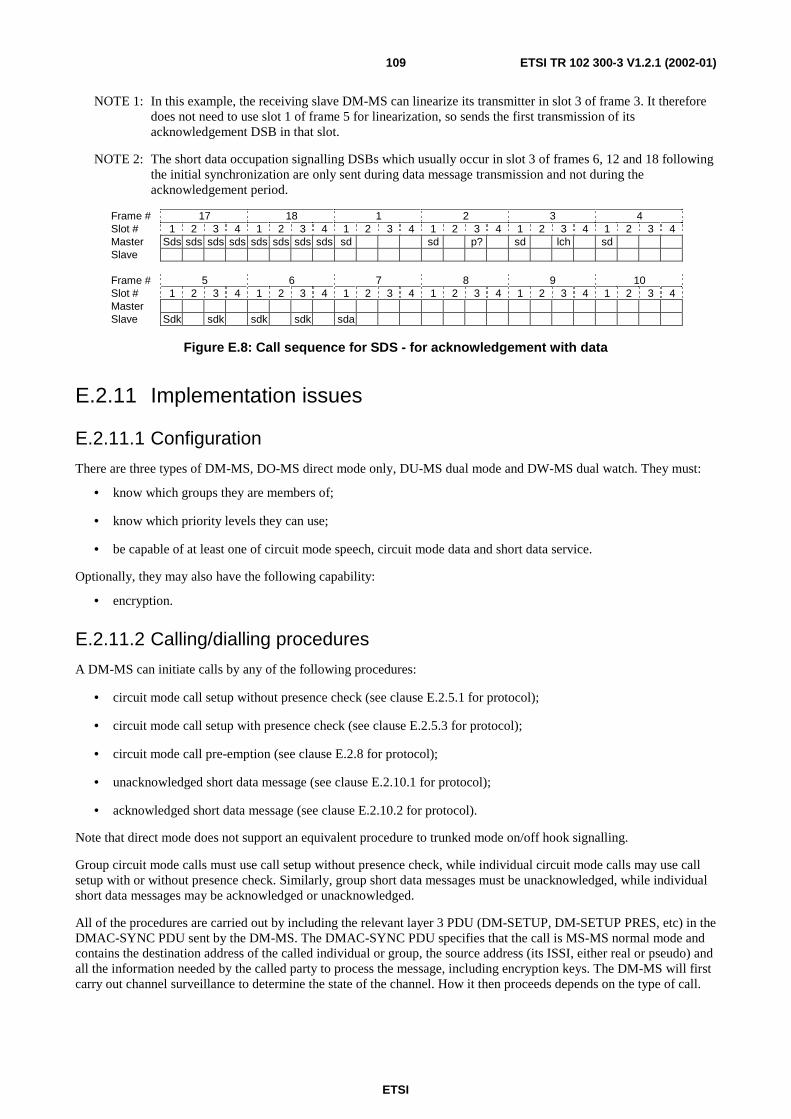
ETSI
ETSI TR 102 300-3 V1.2.1 (2002-01)109
NOTE 1: In this example, the receiving slave DM-MS can linearize its transmitter in slot 3 of frame 3. It therefore does not need to use slot 1 of frame 5 for linearization, so sends the first transmission of its acknowledgement DSB in that slot.
NOTE 2: The short data occupation signalling DSBs which usually occur in slot 3 of frames 6, 12 and 18 following the initial synchronization are only sent during data message transmission and not during the acknowledgement period.
Frame # 17 18 1 2 3 4 Slot # 1 2 3 4 1 2 3 4 1 2 3 4 1 2 3 4 1 2 3 4 1 2 3 4 Master Sds sds sds sds sds sds sds sds sd sd p? sd lch sd Slave Frame # 5 6 7 8 9 10 Slot # 1 2 3 4 1 2 3 4 1 2 3 4 1 2 3 4 1 2 3 4 1 2 3 4 Master Slave Sdk sdk sdk sdk sda
Figure E.8: Call sequence for SDS - for acknowledgement with data
E.2.11 Implementation issues
E.2.11.1 Configuration
There are three types of DM-MS, DO-MS direct mode only, DU-MS dual mode and DW-MS dual watch. They must:
• know which groups they are members of;
• know which priority levels they can use;
• be capable of at least one of circuit mode speech, circuit mode data and short data service.
Optionally, they may also have the following capability:
• encryption.
E.2.11.2 Calling/dialling procedures
A DM-MS can initiate calls by any of the following procedures:
• circuit mode call setup without presence check (see clause E.2.5.1 for protocol);
• circuit mode call setup with presence check (see clause E.2.5.3 for protocol);
• circuit mode call pre-emption (see clause E.2.8 for protocol);
• unacknowledged short data message (see clause E.2.10.1 for protocol);
• acknowledged short data message (see clause E.2.10.2 for protocol).
Note that direct mode does not support an equivalent procedure to trunked mode on/off hook signalling.
Group circuit mode calls must use call setup without presence check, while individual circuit mode calls may use call setup with or without presence check. Similarly, group short data messages must be unacknowledged, while individual short data messages may be acknowledged or unacknowledged.
All of the procedures are carried out by including the relevant layer 3 PDU (DM-SETUP, DM-SETUP PRES, etc) in the DMAC-SYNC PDU sent by the DM-MS. The DMAC-SYNC PDU specifies that the call is MS-MS normal mode and contains the destination address of the called individual or group, the source address (its ISSI, either real or pseudo) and all the information needed by the called party to process the message, including encryption keys. The DM-MS will first carry out channel surveillance to determine the state of the channel. How it then proceeds depends on the type of call.

ETSI
ETSI TR 102 300-3 V1.2.1 (2002-01)110
For circuit mode calls, if the channel is free the DM-MS will then initiate the call. The destination address can be plain or encrypted. If the channel is reserved or occupied the DM-MS may be able to initiate the call if it is able to pre-empt the current call. Note that a normal mode DM-MS is not able to pre-empt a frequency efficient call.
For short data messages, in addition to the procedures for circuit mode calls, a master DM-MS in a circuit mode call can send an unacknowledged short data message by stealing from the traffic capacity, or a slave DM-MS in a circuit mode call can become the master by pre-emption or changeover and then send a short data message.
E.3 Repeater Type 1A
E.3.1 DM protocol layering The DM protocol stack for a type 1A DM-REP operation is the same as for direct MS-MS operation. See clause E.2.1.
E.3.2 Direct mode functionality In addition to the basic DM functionality in clause E.2.2, type 1A DM repeaters offer the following:
• stabilization and extension of coverage area;
• an optional protocol to signal that the repeater is available.
E.3.3 Physical resources A DM call takes place on a "DM channel". With repeater type 1A operation, only one DM channel may exist on one DM RF carrier. Frequency synchronization is provided by the DM-REP. Timing synchronization is provided by the master DM-MS. The DM-REP synchronizes its timing to the master DM-MS, and the slave DM-MSs then synchronize their timing to the DM-REP. A slave DM-MS may request a timing change, for example if it is dual watching.
E.3.4 Slot timing diagrams The method of operation of DM protocol with a type 1A repeater is best illustrated using slot timing diagrams. The abbreviations used are the same as in MS-MS normal mode, see clause E.2.4, with the addition that an abbreviation with a (') indicates a repeated transmission sent by the repeater, on either the master link or the slave link.
E.3.4.1 Constraints on the frame structure (including synchronization)
The constraints on type 1A repeater operation are the same as in MS-MS normal mode, see clause E.2.4.1, except that:
• pre-emption signalling is permitted, during occupation, in slot 3 of slave link frames 2, 5, 8, 11, 14 and 17; the DM-REP then re-transmits the pre-emption message to the current master DM-MS in slot 3 of master link frame 4, 7, 10, 13, 16, or 1 respectively;
• frames 1, 7 and 13 of the master link may carry a DM-REP presence signal in a DSB in slot 3.
E.3.4.2 Direct mode operation
For a repeater and MSs to operate in DM repeater mode they must first tune to a suitable RF carrier and then determine the state of that carrier.
The means by which the repeater and MSs select the appropriate RF carrier on which to operate is not specified in the direct mode standard. The available channels are likely to be programmed into the radio and selection will be made by the user via a channel select knob or a keypad, just as with conventional non-trunked analogue equipment.

ETSI
ETSI TR 102 300-3 V1.2.1 (2002-01)111
When the channel has been chosen, the repeater then continuously carries out a monitoring process in order to detect any signalling that may be present on the channel. This serves two main purposes: firstly it enables the repeater to detect calls that are addressed through it; secondly, it permits the repeater to know if other users are on the channel, preventing it from (optionally) signalling its presence and availability to forward calls addressed through it. On detecting a call addressed through it, the repeater can then take the appropriate action to either forward the call or ignore it if the channel is busy. This monitoring process is called channel surveillance and is described in more detail in clause 8.11.
When the repeater is operational, it sends its presence signal when it is forwarding a call and optionally when the channel is free, so that MSs monitoring the channel can inform their users that the repeater is available. The means by which the MSs inform their users is not specified in the DMO standard [13].
E.3.5 Call set-up protocol In DMO through a type 1 DM-REP there are two options for call set-up:
• a set-up without presence checking whereby transmission commences without explicit knowledge of the presence of any receiving DM-MS(s);
• a set-up with presence checking whereby a specific acknowledgement is sought before transmission commences.
For calls to an individual radio either type of call set-up may be used. For calls to a group, only call set-up without presence check may be used. In both cases the calling DM-MS monitors the slave link in order to determine that the DM-REP has successfully received and re-transmitted the messages.
E.3.5.1 Call set-up without presence check
For group (point-to-multipoint) and individual (point-to-point) calls a set-up without presence check is the most basic mode of setting up a call in a DM channel. Figure E.9 illustrates this procedure.
master link 17 18 1 2 3 1 2 3 4 1 2 3 4 1 2 3 4 1 2 3 4 1 2 3 4 master-rep su su su su su su su tc lch rep-master lch slave link 17 18 1 2 3 1 2 3 4 1 2 3 4 1 2 3 4 1 2 3 4 1 2 3 4 rep-slave su' su' su' su' su' su' su' su' tc' lch slave-rep p? lch master link 4 5 6 7 8 1 2 3 4 1 2 3 4 1 2 3 4 1 2 3 4 1 2 3 4 master-rep tc tc tc occ tc tc rep-master p?' rps slave link 4 5 6 7 8 1 2 3 4 1 2 3 4 1 2 3 4 1 2 3 4 1 2 3 4 rep-slave tc' tc' tc' occ' tc' tc' slave-rep p? p?
Figure E.9: Call sequence for set-up without presence check through type 1 DM-REP
After following the channel surveillance procedures to ascertain the state of the channel, provided the channel is found to be in the state "free", the calling DM-MS may linearize its transmitter. It then establishes the channel synchronization and simultaneously its role as "master" by transmitting a sequence of call set-up messages on the master link. These are sent in an appropriate number of frames, using the DSB structure as given in ETS 300 396-2 [2], clause 9.4.3. These synchronization bursts contain frame count information which defines their position in the timing structure of the 18-frame cyclic multiframe structure. In the example shown in figure E.9, 7 synchronization bursts ("su" in figure E.9) are sent containing frame count information defining their position in frames 17 and 18 of the master link.
The master DM-MS then listens for the synchronization bursts to be re-transmitted by the DM-REP on the slave link in order to confirm that its signalling to the DM-REP was successful. The DM-REP may transmit in a different number of frames from the number used by the master DM-MS. However, in this example, it sends synchronization bursts in 2 frames giving a total of 8 bursts.

ETSI
ETSI TR 102 300-3 V1.2.1 (2002-01)112
The master DM-MS then transmits traffic ("tc" in figure E.9) using the DNB structure, as given in ETS 300 396-2 [2], clause 9.4.3, in the next available frame which in this example is frame 3 of the master link.
Figure E.9 also illustrates the position of slots which are allocated to allow pre-emption requests to be made ("p?" in figure E.9), the slots available for linearization ("lch" in figure E.9), and the synchronization bursts indicating occupation of the channel ("occ" in figure E.9) which occur in slot 3 of frames 6, 12 and 18 following the initial synchronization.
In this example, pre-emption opportunities occur in slot 3 of frames 2, 5 and 8 on the slave link. A pre-emption request made in slot 3 of frame 2 on the slave link would have been re-transmitted 5 slots later in slot 3 of frame 4 on the master link.
Figure E.9 also shows the transmission of the DM-REP presence signal in slot 3 of frame 7 on the master link. (This slot would have been used for the re-transmission of a pre-emption request from a slave if such a request had been received in slot 3 of frame 5 on the slave link.)
E.3.5.2 Call set-up time (fundamental constraints)
Clause E.2.5.2, call set-up time (fundamental constraints) for MS-MS operation applies with the addition that the master MS sends only three call set-up messages in the last frame on the master link, and the repeater then re-sends them on the slave link with four call set-up messages in the last frame. The MS and DM-REP do not have to transmit the same number of frames. The master MS then sends traffic, which is re-sent by the DM-REP three slots later.
If both master and repeater send two frames of call set-up messages, then the time to set up the call is approximately 269 ms. If both master and repeater send four frames of call set-up messages, then the time to set up the call is approximately 496 ms.
E.3.5.3 Call set-up with presence check
For individual (point-to-point) calls, but not for group calls, it is also possible to set up a call using a presence check in order to ascertain the availability of the destination DM-MS. Figure E.10 illustrates this procedure.
master link 17 18 1 2 3
1 2 3 4 1 2 3 4 1 2 3 4 1 2 3 4 1 2 3 4
master-rep sup sup sup sup sup sup sup
rep-master
slave link 17 18 1 2 3
1 2 3 4 1 2 3 4 1 2 3 4 1 2 3 4 1 2 3 4
rep-slave sup' sup' sup' sup' sup' sup' sup' sup'
slave-rep lch cn cn cn
master link 4 5 6 7 8
1 2 3 4 1 2 3 4 1 2 3 4 1 2 3 4 1 2 3 4
master-rep cnk cnk tc tc
rep-master cn' cn' cn' rps
slave link 4 5 6 7 8
1 2 3 4 1 2 3 4 1 2 3 4 1 2 3 4 1 2 3 4
rep-slave cnk' cnk' tc' tc'
slave-rep p?
Figure E.10: Call sequence for set-up with presence check through type 1 DM-REP

ETSI
ETSI TR 102 300-3 V1.2.1 (2002-01)113
The procedure starts in a similar manner to the set-up without presence check, but the set-up message in the synchronization burst ("sup" in figure E.10, with 7 being sent in this example) now requests a response indicating the presence of the DM-MS which has been addressed as the recipient in the set-up attempt. This DM-MS which is defined as a "slave" for the transaction responds on the slave link with the connect message ("cn" in figure E.10) indicating its wish to receive the call. In this example, the slave linearizes its transmitter in slot 1 of frame 2 of the slave link, sending a connect message in slot 3 of this frame and then repeating the connect message in the following frame. The connect message is re-transmitted by the DM-REP to the master DM-MS in the appropriate frames on the master link, in this case frames 4 and 5. On receipt of a connect message, the master responds with a connection acknowledgement message ("cnk" in figure E.10) sent in at least one frame and then, in this example, begins traffic transmission in frame 7 of the master link.
E.3.6 Late entry The ability to late enter a call is an intrinsic feature of TETRA direct mode. This permits an MS which for some reason missed the initial call set-up messages, to enter the call while it is still in progress.
This is achieved by causing the currently transmitting master MS to periodically send "occupation" messages. These are sent using DSBs in slot 3 of master link frames 6, 12 and 18 and also in slot 1 of master link frame 18 and are re-transmitted by the DM-REP on the slave link. These occupation messages are very similar to the original call set-up messages and contain all the information necessary to join the call. As these are sent 4 times a second it permits many chances to late enter an ongoing call.
These occupation messages can also be received by other idle MSs which are carrying out channel surveillance, and serve to indicate that the channel is currently in use and by whom (encryption permitting).
Late entry is generally only applicable for calls set up without presence check as it is these calls that proceed without an acknowledgement from the called DM-MS.
E.3.7 Channel reservation and changeover in a call In a DM call through a type 1 DM-REP, each call transaction constitutes a separate transmission, with a designated master and slave(s) for each call transaction. The procedure for terminating one call transaction and starting another during a call is termed changeover and is illustrated in figure E.11.
master link 11 12 13 14 15
1 2 3 4 1 2 3 4 1 2 3 4 1 2 3 4 1 2 3 4
master-rep tc txc txc txc
rep-master rps txr'
slave link 11 12 13 14 15
1 2 3 4 1 2 3 4 1 2 3 4 1 2 3 4 1 2 3 4
rep-slave tc' txc' txc' txc'
slave-rep p? txr p?
master link 16 17 18 1 2
1 2 3 4 1 2 3 4 1 2 3 4 1 2 3 4 1 2 3 4
master-rep txa txa txa txa *su su su
rep-master
slave link 16 17 18 1 2
1 2 3 4 1 2 3 4 1 2 3 4 1 2 3 4 1 2 3 4
rep-slave txa' txa' txa' txa' su' su' su' su' su' su' su' su'
slave-rep
NOTE: * indicates start of transmissions by new master DM-MS.
Figure E.11: Call sequence for changeover in call through type 1 DM-REP (no collisions)
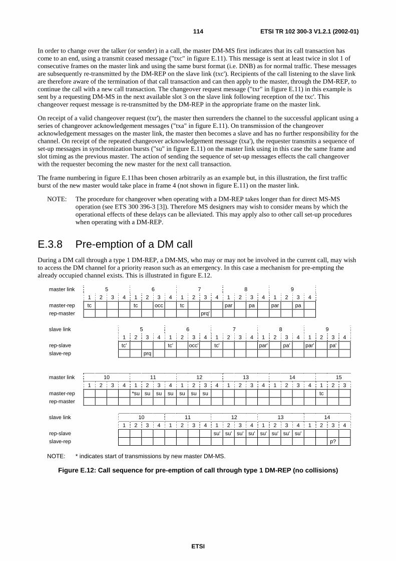
ETSI
ETSI TR 102 300-3 V1.2.1 (2002-01)114
In order to change over the talker (or sender) in a call, the master DM-MS first indicates that its call transaction has come to an end, using a transmit ceased message ("txc" in figure E.11). This message is sent at least twice in slot 1 of consecutive frames on the master link and using the same burst format (i.e. DNB) as for normal traffic. These messages are subsequently re-transmitted by the DM-REP on the slave link (txc'). Recipients of the call listening to the slave link are therefore aware of the termination of that call transaction and can then apply to the master, through the DM-REP, to continue the call with a new call transaction. The changeover request message ("txr" in figure E.11) in this example is sent by a requesting DM-MS in the next available slot 3 on the slave link following reception of the txc'. This changeover request message is re-transmitted by the DM-REP in the appropriate frame on the master link.
On receipt of a valid changeover request (txr'), the master then surrenders the channel to the successful applicant using a series of changeover acknowledgement messages ("txa" in figure E.11). On transmission of the changeover acknowledgement messages on the master link, the master then becomes a slave and has no further responsibility for the channel. On receipt of the repeated changeover acknowledgement message (txa'), the requester transmits a sequence of set-up messages in synchronization bursts ("su" in figure E.11) on the master link using in this case the same frame and slot timing as the previous master. The action of sending the sequence of set-up messages effects the call changeover with the requester becoming the new master for the next call transaction.
The frame numbering in figure E.11has been chosen arbitrarily as an example but, in this illustration, the first traffic burst of the new master would take place in frame 4 (not shown in figure E.11) on the master link.
NOTE: The procedure for changeover when operating with a DM-REP takes longer than for direct MS-MS operation (see ETS 300 396-3 [3]). Therefore MS designers may wish to consider means by which the operational effects of these delays can be alleviated. This may apply also to other call set-up procedures when operating with a DM-REP.
E.3.8 Pre-emption of a DM call During a DM call through a type 1 DM-REP, a DM-MS, who may or may not be involved in the current call, may wish to access the DM channel for a priority reason such as an emergency. In this case a mechanism for pre-empting the already occupied channel exists. This is illustrated in figure E.12.
master link 5 6 7 8 9
1 2 3 4 1 2 3 4 1 2 3 4 1 2 3 4 1 2 3 4
master-rep tc tc occ tc par pa par pa
rep-master prq'
slave link 5 6 7 8 9
1 2 3 4 1 2 3 4 1 2 3 4 1 2 3 4 1 2 3 4
rep-slave tc' tc' occ' tc' par' pa' par' pa'
slave-rep prq
master link 10 11 12 13 14 15
1 2 3 4 1 2 3 4 1 2 3 4 1 2 3 4 1 2 3 4 1 2 3
master-rep *su su su su su su su tc
rep-master
slave link 10 11 12 13 14
1 2 3 4 1 2 3 4 1 2 3 4 1 2 3 4 1 2 3 4
rep-slave su' su' su' su' su' su' su' su'
slave-rep p?
NOTE: * indicates start of transmissions by new master DM-MS.
Figure E.12: Call sequence for pre-emption of call through type 1 DM-REP (no collisions)

ETSI
ETSI TR 102 300-3 V1.2.1 (2002-01)115
The first master sequence in figure E.12 shows normal progress of a call through a type 1 DM-REP, with traffic bursts in slot 1 of each frame (1 to 17) on the master link being re-transmitted by the DM-REP on the slave link. A DM-MS wishing to use the channel would, if not participating in the call, have had to first determine the state of the channel and in this illustration would have identified that the ongoing call is a type 1 call being transmitted through a DM-REP. The pre-empting DM-MS would then have synchronized to the DM-REP transmissions on the slave link and in the process determined the timing state of the channel, including the slave link frame and slot numbers.
To effect the pre-emption, the DM-MS transmits a pre-emption request message ("prq" in figure E.12) at an appropriate position in the slave link frame structure. During occupation, pre-emption is allowed only in slot 3 of slave link frames 2, 5, 8, 11, 14 and 17. When the master successfully decodes the repeated pre-emption request on the master link, assuming it is a valid request, it announces that the channel has been pre-empted to both the pre-empting DM-MS and the other DM-MSs which were involved in the ongoing call. This announcement is by means of the pre-emption acknowledgement message ("par" and "pa" in figure E.12) sent on the master link and subsequently repeated on the slave link. Having issued the pre-emption acknowledgement messages the master ceases its role and relinquishes the channel.
The successful pre-emptor now transmits set-up messages to the DM-REP using the master link for the new call, with a new group or individual addressee, and becomes master for the initial transaction of this new call. In this example the traffic transmissions begin in slot 1 of frame 15 on the master link.
NOTE: In this example, the pre-empting DM-MS has not included a timing adjustment indication within the pre-emption request and so, in the new call set-up, it adopts the timing reference and frame numbering used by the old master DM-MS.
E.3.9 Terminating a call At the end of a call transaction, the master DM-MS sends transmit ceased messages (as usual) and then provides reservation DSBs in frames 6, 12 and 18; these messages are re-transmitted by the DM-REP on the slave link. If the channel reservation timer expires without either a changeover of the master role having occurred or the master DM-MS resuming traffic transmission then the master DM-MS stops sending reservation DSBs and the call ends.
Alternatively, the master DM-MS may terminate the call prematurely by sending channel release messages (DM-RELEASE PDU). The DM-REP re-transmits these messages on the slave link.
E.3.10 DM short data call DM short data messages can use either unacknowledged or acknowledged protocols.
E.3.10.1 Unacknowledged short data message
A DM-MS wishing to send an unacknowledged short data message through a type 1 DM-REP follows the procedures to ascertain the state of the channel. Provided that the channel is found to be in the state "free" the DM-MS may linearize its transmitter. It then establishes the channel synchronization and simultaneously its role as "master" by transmitting a sequence of DM-SDS UDATA message headers on the master link, in an appropriate number of frames, using the DSB structure. The DM-SDS UDATA message headers contain frame count information which defines their position in the timing structure of the 18-frame cyclic multiframe structure. In the example shown in figure E.13, 7 synchronization bursts ("sdu" in figure E.13) are sent containing frame count information defining their position in frames 17 and 18.
The master DM-MS then listens for the DM-SDS UDATA message headers to be re-transmitted by the DM-REP on the slave link in order to confirm that its signalling to the DM-REP was successful. The DM-REP may transmit in a different number of frames from the number used by the master DM-MS. However, in this example, it sends synchronization bursts in 2 frames giving a total of 8 bursts.
The master DM-MS then transmits the remaining parts of the short data message ("sd" in figure E.13), without repetition and using the DNB structure, in slot 1 of the following frames. In this example the remaining parts of the message occupy two slots and are sent in frames 3 and 4.
For reliability, the master DM-MS may repeat the complete message transmission immediately (without re-checking that the channel is free), and starting again with DSBs. In this example there is one message repetition, with the DSBs sent in frames 5 and 6; the two DNBs (not shown in figure E.13) are sent in frames 9 and 10.

ETSI
ETSI TR 102 300-3 V1.2.1 (2002-01)116
Figure E.13 also illustrates where pre-emption signalling is permitted during an SDS transmission.
master link 17 18 1 2 3
1 2 3 4 1 2 3 4 1 2 3 4 1 2 3 4 1 2 3 4
master-rep sdu sdu sdu sdu sdu sdu sdu sd lch
rep-master lch
slave link 17 18 1 2 3
1 2 3 4 1 2 3 4 1 2 3 4 1 2 3 4 1 2 3 4
rep-slave sdu' sdu' sdu' sdu' sdu' sdu' sdu' sdu' sd' lch
slave-rep p? lch
master link 4 5 6 7 8
1 2 3 4 1 2 3 4 1 2 3 4 1 2 3 4 1 2 3 4
master-rep sd sdu sdu sdu sdu sdu sdu sdu
rep-master p?'
slave link 4 5 6 7 8
1 2 3 4 1 2 3 4 1 2 3 4 1 2 3 4 1 2 3 4
rep-slave sd' sdu' sdu' sdu' sdu' sdu' sdu' sdu' sdu'
slave-rep p?
Figure E.13: Call sequence for SDS (for unacknowledged data) through type 1 DM-REP
E.3.10.2 Acknowledged short data message
When sending short data to an individual DM-MS, the calling DM-MS may request an acknowledgement from the called DM-MS. Figure E.14 illustrates the procedure for an acknowledged short data message comprising the DM-SDS DATA message headers followed by three DNBs.
The procedure starts in a similar manner to an unacknowledged short data message, but the DM-SDS DATA message headers request an acknowledgement from the receiving slave DM-MS. The slave DM-MS sends the acknowledgement following the receipt of the last burst containing data. In this example the slave DM-MS sends SDS acknowledgement DSBs ("sdk" in figure E.14) in slots 1 and 3 of frames 6 and 7 of the slave link. The acknowledgement is re-transmitted by the DM-REP to the master DM-MS in the appropriate frames on the master link, in this case frames 8 and 9.
NOTE 1: In this example, the receiving slave DM-MS may linearize its transmitter in slot 3 of slave link frame 3. It therefore does not need to use slot 1 of slave link frame 6 for linearization, so sends the first transmission of its acknowledgement DSB in that slot.
NOTE 2: The short data occupation signalling DSBs which usually occur in slot 3 of frames 6, 12 and 18 following the initial synchronization are only sent during data message transmission and not during the acknowledgement period.

ETSI
ETSI TR 102 300-3 V1.2.1 (2002-01)117
master link 17 18 1 2 3
1 2 3 4 1 2 3 4 1 2 3 4 1 2 3 4 1 2 3 4
master-rep sds sds sds sds sds sds sds sd lch
rep-master lch
slave link 17 18 1 2 3
1 2 3 4 1 2 3 4 1 2 3 4 1 2 3 4 1 2 3 4
rep-slave sds' sds' sds' sds' sds' sds' sds' sds' sd' lch
slave-rep p? lch
master link 4 5 6 7 8 9
1 2 3 4 1 2 3 4 1 2 3 4 1 2 3 4 1 2 3 4 1 2 3
master-rep sd sd
rep-master p?' p?' sdk' sdk' sdk' sdk'
slave link 4 5 6 7 8
1 2 3 4 1 2 3 4 1 2 3 4 1 2 3 4 1 2 3 4
rep-slave sd' sd'
slave-rep p? sdk sdk sdk sdk
Figure E.14: Call sequence for SDS (for acknowledgement without data) through type 1 DM-REP
E.3.11 Implementation Issues
E.3.11.1 Configuration
All three types of DM-MS (DO-MS direct mode only, DU-MS dual mode and DW-MS dual watch) can be used with a DM-REP, provided that they are configured with the additional protocols to enable operation with a DM-REP. They must be able to recognize the DM-REP presence signal, and read its type and address. They must also:
• know which groups they are members of;
• know which priority levels they can use;
• be capable of at least one of circuit mode speech, circuit mode data and short data service;
• have a procedure for switching from MS-MS mode to repeater mode.
Optionally, they may also have the following capabilities:
• automatic procedure for switching from MS-MS mode to repeater mode;
• encryption.
The options for the DM-REP are:
• presence signal on free channel - the repeater may optionally transmit its presence signal when it considers that the channel is free. This is recommended as all MSs monitoring the channel are notified of its presence and availability. It is also recommended that the DM-REP sends the signal at irregular intervals to avoid repeated collisions if other DM-REPs or gateways are trying to use the channel. The repetition rate is controlled by the two timers DT253 and DT254, which are the minimum and maximum intervals respectively. Setting them to be equal results in regular transmissions;
• usage restriction type - this parameter determines which MSs may use the DM-REP. It can be no restriction (open), or restricted by prior arrangement, to a single network identity, or to one, two or three addresses (individual or group). More addresses can be added by sending them in more URTs in further presence signals. Addresses can be deleted by sending URTs with zero time validity;
• maximum power class of MS - this can be used to restrict the maximum power transmitted by MSs using the DM-REP;

ETSI
ETSI TR 102 300-3 V1.2.1 (2002-01)118
• dual watch synchronization flag - this is part of the presence signal, and informs listening mobiles not performing dual watch if the DM-REP considers that its timing is synchronized for dual watch, so that DO-MSs know to use the DM-REP timing to avoid preventing DW-MSs from full dual watching.
E.3.11.2 Calling/dialling procedures
A DM-MS can initiate calls through a DM-REP by any of the following procedures:
• circuit mode call setup without presence check (see clause E.3.5.1 for protocol);
• circuit mode call setup with presence check (see clause E.3.5.3 for protocol);
• circuit mode call pre-emption (see clause E.3.8 for protocol);
• unacknowledged short data message (see clause E.3.10.1 for protocol);
• acknowledged short data message (see clause E.3.10.2 for protocol).
Note that direct mode does not support an equivalent procedure to trunked mode on/off hook signalling.
Group circuit mode calls must use call setup without presence check, while individual circuit mode calls may use call setup with or without presence check. Similarly, group short data messages must be unacknowledged, while individual short data messages may be acknowledged or unacknowledged.
All of the procedures are carried out by including the relevant layer 3 PDU (DM-SETUP, DM-SETUP PRES, etc) in the DMAC-SYNC PDU sent by the DM-MS. The DMAC-SYNC PDU specifies that the call is via a DM-REP and contains the DM-REP address, whether the PDU is being sent on the slave link or the master link, the source address (the DM-MS's ISSI, either real or pseudo), the destination address of the called individual or group and all the information needed by the called party to process the message, including encryption keys. The DM-MS will first carry out channel surveillance to determine the state of the channel. How it then proceeds depends on the type of call.
For circuit mode calls, if the channel is free, the DM-MS will then initiate the call. Obviously it must know the DM-REP address, either from the presence signal or by prior knowledge. It must also have permission to use the DM-REP, either from the Usage Restriction Type in the presence signal or by prior arrangement. The destination address can be plain or encrypted. If the channel is reserved or occupied the DM-MS may be able to initiate the call if it is able to pre-empt the current call.
For short data messages, in addition to the procedures for circuit mode calls, a master DM-MS in a circuit mode call can send an unacknowledged short data message by stealing from the traffic capacity, or a slave DM-MS in a circuit mode call can become the master by pre-emption or changeover and then send a short data message.
E.3.11.3 Operational procedures
Deployment of DM-REPs needs to be planned in advance. The following decisions must be made:
• which frequency will be used;
• will the DM-REP transmit its presence signal when the channel is free, and how frequently;
• will access to the DM-REP be open or controlled;
• if controlled, by prior arrangement or by inclusion in the presence signal.
E.3.11.4 Constraints
Proximity to other TETRA systems.

ETSI
ETSI TR 102 300-3 V1.2.1 (2002-01)119
E.4 Repeater Type 1B The type 1B repeater is very similar to the type 1A, the major difference being that its downlink and uplink channels are on different frequencies. For this reason, the subclauses in clause E.4 only cover the differences, and the corresponding subclause in clause E.3 should be referred to for full information.
E.4.1 DM protocol layering See clause E.3.1.
E.4.2 Direct mode functionality In addition to the basic DM functionality in clause E.2.2, type 1B DM repeaters offer the following:
• stabilization and extension of coverage area;
• an optional protocol to signal that the repeater is available;
• improved co-existence with trunked mode networks due to the two frequency operation.
E.4.3 Physical resources A DM call takes place on a "DM channel". With repeater type 1B operation, only one DM channel may exist on a pair of DM RF carriers. Frequency synchronization is provided by the DM-REP. Note that the DM-MSs align their frequency with the DM-REP's downlink carrier and use that reference when transmitting on the uplink carrier. Timing synchronization is provided by the master DM-MS. The DM-REP synchronizes its timing to the master DM-MS, and the slave DM-MSs then synchronize their timing to the DM-REP. A slave DM-MS may request a timing change, for example if it is dual watching.
E.4.4 Slot timing diagrams See clause E.3.4.
E.4.4.1 Constraints on the frame structure (including synchronization)
See clause E.3.4.1.
E.4.4.2 Direct mode operation
Clause E.3.4.2 applies, except that the repeater and MSs must tune to a suitable duplex pair of RF carriers. The MSs will monitor the repeater's downlink frequency, while the repeater will monitor its uplink frequency.
E.4.5 Call set-up protocol See clause E.3.5.
E.4.5.1 Call set-up without presence check
See clause E.3.5.1. Note that both the master and slave links use one RF carrier for signalling from MSs to DM-REP and the other for signalling from DM-REP to the MSs.
E.4.5.2 Call set-up time (fundamental constraints)
See clause E.3.5.2.

ETSI
ETSI TR 102 300-3 V1.2.1 (2002-01)120
E.4.5.3 Call set-up with presence check
See clause E.3.5.3.
E.4.6 Late entry See clause E.2.6.
E.4.7 Channel reservation and changeover in a call See clause E.3.7.
E.4.8 Pre-emption of a DM call See clause E.3.8.
E.4.9 Terminating a call See clause E.3.9.
E.4.10 DM short data call See clause E.3.10.
E.4.10.1 Unacknowledged short data message
See clause E.3.10.1.
E.4.10.2 Acknowledged short data message
See clause E.3.10.2.
E.4.11 Implementation Issues
E.4.11.1 Configuration
See clause E.3.11.1. Note that the DM-MS will need to know the uplink and downlink frequencies, either by prior knowledge or from the DM-REP presence signal.
E.4.11.2 Calling/dialling procedures
See clause E.3.11.2.
E.4.11.3 Operational procedures
See clause E.3.11.3.
E.4.11.4 Constraints
See clause E.3.11.4.

ETSI
ETSI TR 102 300-3 V1.2.1 (2002-01)121
E.5 Gateway
E.5.1 DM protocol layering The protocol stack for operation with a DM-GATE operation is shown in figure E.15. It is the same as for MS-MS and repeater operation with the addition of a Direct Mode Mobility Management (DMMM) entity to support the additional optional procedure of registration.
DM AI Layer 2
DM AI Layer 1
Direc t Mode Call Control
Data Link Layer
Physical Layer
DM AI Layer 3
Short Data
Control Plane User Plane Call Control Information
Intrinsic Services
Mobility Management
Speech
Circuit Mode Data
Direct Mode
Registration
Figure E.15: DM-MS protocol stack for operation with a gateway
E.5.2 Direct mode functionality In addition to the basic DM functionality in clause E.2.2, DM-GATEs offer the following:
• connection of DM-MSs to the V+D trunking system in individual and group calls;
• stabilization and extension of V+D to DM coverage;
• an optional protocol to signal that the gateway is available.
E.5.3 Physical resources A DM call takes place on a DM channel. With gateway operation, only one DM channel may exist on one DM RF carrier. Frequency and timing synchronization are both provided by the DM-GATE. If a DM-MS wishes to make a call through a DM-GATE, but has not received signals from the DM-GATE sufficiently recently, it chooses an arbitrary timing. The DM-GATE can then announce a modification of the timing, and the DM-MS will align its timing to the DM-GATE.
E.5.4 Slot timing diagrams The method of operation of a DM-GATE is best illustrated using slot timing diagrams. The procedures and sequences given in the following clauses are intended to illustrate possible scenarios and the mechanisms which the protocol may take in those circumstances for DM-MS operation with a gateway. The gateway operates on a single carrier frequency on the DM air interface and on a frequency pair on the V+D interface. A gateway can support only one call at a time.
The procedures presented here are not exhaustive and are not intended to show every possible scenario.

ETSI
ETSI TR 102 300-3 V1.2.1 (2002-01)122
In particular, the V+D SwMI may use the protocol facilities for call set-up and channel usage for circuit mode calls in many different ways. For example:
• early or late channel assignment;
• transmission, quasi-transmission or message trunking;
• demanded layer 2 acknowledgements or repeated transmissions of Protocol Data Units (PDUs).
In the particular examples presented here the following assumptions have been made about the operation of the V+D trunked system:
• The gateway and the V+D MS are located within the same cell and are allocated the same traffic channel (i.e. the same timeslot on the same V+D carrier).
• The SwMI demands layer 2 acknowledgements rather than using repeated transmissions for individually addressed messages. In the case of a channel allocation, the acknowledgement is requested on the allocated traffic channel.
• The called MSs are paged successfully on the first attempt.
• There are no signalling collisions.
Abbreviations are used in the diagrams to represent PDUs sent within the protocol. The actual message types are as follows:
su = DM-SETUP sup = DM-SETUP PRES occ = DM-OCCUPIED txc = DM-TX CEASED cn = DM-CONNECT cnk = DM-CONNECT ACK gak = DM-GACK gtxa = DM-GTX ACCEPT gtxr = DM-GTX REQUEST gpa = DM-GPRE ACCEPT (sent in DSB) gpac = DM-GPRE ACCEPT + DM-TX CEASED (sent in DNB) gsu = DM-GSETUP gcn = DM-GCONNECT gprq = DM-GPREEMPT usu = U-SETUP utxd = U-TX DEMAND utxc = U-TX CEASED ucn = U-CONNECT dsu = D-SETUP dscn = D-SETUP + D-CONNECT dscp = D-SETUP + D-CALL PROCEEDING dcnk = D-CONNECT + D-CONNECT ACKNOWLEDGE dtxg = D-TX GRANTED dtxc = D-TX CEASED dtgi = D-TX GRANTED + D-TX INTERRUPT
Other abbreviations used are:
- gps, representing the gateway presence signal;
- tc1, tc2 .... etc, representing traffic transmissions;
- lch, representing slots available for linearization;
- p?, representing slots available for pre-emption requests;
- l2a, representing a layer 2 acknowledgement;
- npd, representing a null PDU.

ETSI
ETSI TR 102 300-3 V1.2.1 (2002-01)123
NOTE: In all cases an abbreviation with a (') indicates a transmission repeated once whereas an abbreviation with a ('') indicates a transmission which has been repeated twice.
E.5.4.1 Constraints on the frame structure (including synchronization)
The constraints on gateway operation are the same as in MS-MS normal mode, with the addition that:
• frames 1, 7 and 13 of the master link may carry a DM-GATE presence signal in a DSB in slot 3.
E.5.4.2 Direct mode operation
For a gateway and MSs to operate in DM gateway mode they must first tune to a suitable RF carrier and then determine the state of that carrier.
The means by which the gateway and MSs select the appropriate DM RF carrier on which to operate is not specified in the direct mode standard. The available channels are likely to be programmed into the radio and selection will be made by the user via a channel select knob or a keypad, just as with conventional non-trunked analogue equipment.
The gateway registers and authenticates to the SwMI using its own ITSI.
The gateway may generate a presence signal on the DM RF carrier after it has successfully registered and authenticated to the SwMI. The purpose of this signal is to inform any DM-MSs monitoring the RF carrier that the gateway is now present and available for service, and to provide frame and slot numbering.
The gateway is specifically addressed by a DM-MS if a connection is required to be made with the V+D system, by inclusion of the gateway address within the call set-up messages.
E.5.5 Call set-up protocol In Direct Mode operation there are two options for call set-up: a call set-up without presence checking whereby transmission commences without explicit knowledge of the presence of any receiving DM-MS(s), and set-up with presence checking whereby a specific acknowledgement is sought before transmission commences. For group (point-to-multipoint) and individual (point-to-point) calls a call set-up without presence check is the most basic mode of setting up a call in a DM channel.
In V+D operation there are also two methods for call set-up, dependent on the selection of hook signalling. Direct set-up does not employ hook signalling and the call is established irrespective of the presence of the user. Set-up with hook signalling requires the user to be present and to accept the call.
The examples presented here show the fastest possible call set-up by assuming that processing delays within the SwMI are negligible. It is also assumed that the gateway is broadcasting a presence signal and the DM-MSs have aligned their timing, on the DM channel, in a suitable manner with that signal.
E.5.5.1 Group call from V+D to DM-MS via a DM-GATE
The message sequence diagram illustrated in figure E.16 shows the signalling transactions involved in setting up a group call from a V+D MS via a DM-GATE. The diagram shows the layer 3 PDUs and does not show any layer 2 signalling.
The process starts when the V+D MS sends a U-SETUP message to the SwMI which responds with a D-CONNECT and a D-SETUP message sent within the same slot. On receipt of the D-SETUP the gateway initiates a call set-up on the DM channel by sending the DM-SETUP message.
The V+D MS which originated the call will, on receipt of the D-CONNECT message, start to send its traffic which is relayed by the SwMI to the gateway and by the gateway on the DM channel once it has finished sending the DM-SETUP messages.

ETSI
ETSI TR 102 300-3 V1.2.1 (2002-01)124
DM-MS DM-GATE SwMI MS
DM-SETUP(su)
U-SETUP(usu)
D-SETUP(part of dscn)
D-CONNECT(part of dscn)
TRAFFIC(tc)
Figure E.16: Message sequence chart for group call from V+D via DM-GATE
Example timings of the call set-up can be seen in figure E.17.
This figure shows the slot and frame structure on both the DM RF carrier and the V+D system uplink RF carrier and the downlink RF carrier. The V+D downlink RF carrier is the second line in the figure and shows the signalling messages sent by the V+D base station to the V+D MS and the gateway.
The V+D uplink is a single RF carrier although it is shown twice in figure E.17. The first line in the diagram shows the uplink as used by the V+D MS while the third line shows the signalling on the same uplink frequency from the gateway.
The fourth line on the figure represents the DM RF carrier and shows the signalling between the gateway and the DM-MS. For clarity the RF carrier is shown as two sets of slots.
The four lines are repeated in the bottom half of the figure and are a continuation of the lines in the top half of figure E.17.
Figure E.17 illustrates that the DM channel has been aligned, using the slot and frame numbering broadcast in the presence signal, such that it lags the V+D downlink slot 1 of the main carrier by 3 slots.
The call set-up is initiated by the U-SETUP message from the calling V+D MS in slot 1 of frame 10 on the uplink ('usu' in figure E.17) and the SwMI response of a D-CONNECT message and a D-SETUP message ('dscn' in figure E.17) is sent in slot 1 in frame 11 on the downlink. This is the fastest possible response and assumes that the SwMI has resource immediately available. These messages allocate slot 3 on the same carrier as the traffic channel.
In this example the SwMI has also, in the D-CONNECT message, demanded a layer 2 acknowledgement from the calling MS in a reserved subslot on the allocated traffic channel and this is sent by the V+D MS in slot 3 of frame 11 on the uplink. It then begins to send traffic, starting in slot 3 of frame 12.
The gateway, after receiving the D-SETUP giving slot 3 as the channel allocation re-aligns the slot and frame numbering on the DM channel (while sending the DM-SETUP messages) to suit this allocation. This can be seen in the figure on the set of slots representing the DM channel where the first DM-SETUP message marks the slot as slot 1 of frame 11 when it would otherwise have been slot 3 of frame 11. The original 3-slot lag used during the signalling phase is maintained when the traffic channel is allocated since this imposes the minimum requirements on the gateway's physical layer. As shown in this example it also avoids the need for the gateway to store and forward a burst of traffic over frame 18.
The DM-SETUP messages are sent in a sequence of synchronization bursts ('su' in figure E.17, with 6 being sent in this example), using the DSB structure as given in EN 300 392-2 [6], clause 9.4.3. These synchronization bursts contain the desired slot and frame count information which defines their position in the timing structure of the 18-frame cyclic multiframe structure and achieves the necessary alignment with the allocated traffic channel on V+D.
The gateway, in this example, sends DM-SETUP messages over 2 frames and then begins relaying the traffic forwarded on the V+D downlink. Note that the DM-SETUP messages are not sent in slot 2 of frames 11 and 12 in order to enable the gateway to receive the V+D downlink traffic slot (since a DM-GATE is not required to be able to transmit and receive at the same time). The reliability of the DM call set-up signalling can be increased by sending more DM-SETUP messages but this could result in the loss of some of the traffic from the V+D MS.

ETSI
ETSI TR 102 300-3 V1.2.1 (2002-01)125
The delay incurred in relaying the traffic from the V+D MS to the DM channel is 5 slots.
Figure E.17 also illustrates the position of DM slots which are allocated to allow pre-emption requests to be made ('p?' in figure E.17), and the synchronization bursts denoting occupation of the DM channel ('occ' in figure E.17) which occur in slot 3 of frames 6 and 12 and slots 1 and 3 of frame 18 following the initial synchronization.
Frame # 10 11 12 13 14 15 Slot # 1 2 3 4 1 2 3 4 1 2 3 4 1 2 3 4 1 2 3 4 1 2 3 4 V+D MS uplink usu l2a tc1 tc2 tc3 tc4 Frame # 10 11 12 13 14 15 16 Slot # 3 4 1 2 3 4 1 2 3 4 1 2 3 4 1 2 3 4 1 2 3 4 1 2
V+D BS downlink dscn
npd tc1' tc2' tc3'
Frame # 10 11 12 13 14 15 Slot # 1 2 3 4 1 2 3 4 1 2 3 4 1 2 3 4 1 2 3 4 1 2 3 4 Gate V+D uplink Frame # 10 11 12 13 14 Slot # 4 1 2 3 4 1 2 3 4 1 2 3 4 1 2 3 4 1 2 3 4 1 Gate to DM-MS su su su su su su tc1'' tc2'' p? tc3'' DM-MS to Gate Frame # 16 17 18 1 2 3 Slot # 1 2 3 4 1 2 3 4 1 2 3 4 1 2 3 4 1 2 3 4 1 2 3 V+D MS uplink tc5 tc6 tc7 tc8 tc9 Frame # 16 17 18 1 2 3 Slot # 3 4 1 2 3 4 1 2 3 4 1 2 3 4 1 2 3 4 1 2 3 4 1 V+D BS downlink tc4' tc5' tc6' tc7' tc8' Frame # 16 17 18 1 2 3 Slot # 1 2 3 4 1 2 3 4 1 2 3 4 1 2 3 4 1 2 3 4 1 2 3 Gate V+D uplink Frame # 15 16 17 18 1 2 Slot # 2 3 4 1 2 3 4 1 2 3 4 1 2 3 4 1 2 3 4 1 2 3 4 Gate to DM-MS tc4'' tc5'' p? occ occ tc6'' tc7'' p? DM-MS to Gate
Figure E.17: Timing diagram for group call from V+D via DM-GATE
E.5.5.2 Group call from DM-MS via a DM-GATE
A group call initiated by a DM-MS to a group whose members are on both the DM channel and the V+D system must take account of the response time of the V+D system. The V+D system may take some time to respond and the gateway waits for the SwMI to respond before proceeding with the call. Figure E.18 illustrates the message exchanges involved in a group call set-up from a DM-MS via a DM-GATE.
The basic philosophy of the message sequence for a request originating from a DM-MS is that it comprises the request, an optional interim acknowledge, then a final acknowledgement (or rejection). In the event of a final acknowledgement then this is followed by a normal DM call set-up and traffic. This same basic message sequence philosophy of request, optional interim acknowledgement and final response, also applies to the processes of individual call set-up, call changeover and pre-emption through a gateway.
During the call set-up the gateway is master of the channel. The calling DM-MS begins the call set-up with the DM-GSETUP message which is sent on the DM channel to the gateway. The gateway then forwards a U-SETUP to the SwMI and waits for a D-CONNECT in response giving the channel allocation. While waiting for the D-CONNECT from the SwMI the gateway may send an acknowledgement to the calling DM-MS (DM-GACK) to prevent repeats of the call set-up request and may then subsequently generate reservation signalling.

ETSI
ETSI TR 102 300-3 V1.2.1 (2002-01)126
On receipt of the D-CONNECT the gateway sends DM-GCONNECT to the calling DM-MS which then assumes the role of master and begins the normal DM call set-up followed by traffic. The DM-SETUP messages and traffic are received by the gateway and also by DM members of the group.
DM-MS DM-GATE SwMI MS
DM-GSETUP(gsu)
U-SETUP(usu)
D-SETUP(part of dscn)
D-CONNECT(part of dscn)
DM-GCONNECT(gcn)
DM-SETUP(su)
TRAFFIC(tc)
Figure E.18: Message sequence chart for group call from DM-MS via DM-GATE
The timing diagram in figure E.19 illustrates this call set-up. The initial alignment of the DM channel to the V+D downlink slot 1 is a 3-slot lag as in the previous example.
After following the procedures to ascertain the state of the channel, provided the channel is found to be in the state "free", the calling DM-MS may linearize its transmitter. It then sends the set-up request messages 'gsu' on the DM channel to the gateway. In this example, the gateway sends the U-SETUP message 'usu' on the V+D uplink 3 slots later having successfully decoded the first set-up burst from the DM-MS. It is a gateway choice as to whether the gateway sends the DM-GACK interim acknowledgement to the calling DM-MS before it sends the call request to the SwMI. In this example, the call request is passed to the V+D system ('usu') without an interim acknowledgement being generated.
The SwMI has resource immediately available and responds by sending the D-SETUP and D-CONNECT messages to the V+D group members and gateway respectively in the same slot ('dscn'). It demands a layer 2 acknowledgement from the gateway in a reserved subslot on the allocated traffic channel, slot 3.
As the SwMI has responded quickly there is no need for the interim acknowledgement to the DM-MS and so the gateway responds to the calling DM-MS with the DM-GCONNECT message. This message is also used to re-align the slot and frame numbering on the DM channel. Again, as in the previous example, the same 3-slot lag is maintained between the DM channel and the allocated V+D traffic channel.
In the meantime, in the absence of genuine traffic, the gateway generates null PDUs on the V+D uplink. After receipt of the DM-GCONNECT from the gateway, the DM-MS assumes the role of master, but follows the new timing established by the gateway, and generates DM-SETUP messages on the DM channel to alert the DM members of the group. It then proceeds to send its traffic which is relayed by the gateway on the V+D uplink 3 slots later and by the SwMI on the V+D downlink a further 2 slots after this.

ETSI
ETSI TR 102 300-3 V1.2.1 (2002-01)127
In this example the slot and frame alignment on the DM channel has been chosen to lag that on the V+D traffic channel, as was done for the example in figure E.17. This means that, for traffic flowing from the V+D channel to the DM channel, the frame 18 alignment is such that there is no need for the gateway to store a burst of traffic. However this same frame alignment means that, for traffic flowing from the DM channel to the V+D channel, the gateway is required to store one burst of traffic across the frame 18 boundary. This may be seen in figure E.19 where the traffic burst tc2 sent in slot 1 of frame 17 on the DM channel cannot be relayed as usual 3 slots later on the V+D uplink as this lies inside a frame 18. The gateway is thus forced to store the traffic burst and to relay it in the next available frame (frame 1). It is recommended that the frame numbering remain consistent with change-over and that the numbering be chosen initially as in the example in figure E.19, with the DM channel numbering lagging that of the V+D downlink.
The figure also illustrates the position of DM slots which are allocated to allow pre-emption requests to be made ('p?' in figure E.19), and the synchronization bursts denoting occupation of the DM channel ('occ' in figure E.19) which occur in slot 3 of frames 6 and 12 and slots 1 and 3 of frame 18 following the initial synchronization. It also shows, in slot 3 of frame 1 on the DM channel, the gateway presence signal which is transmitted by the gateway in slot 3 of frames 1, 7 and 13 during occupation by a DM-MS as master.
Frame # 10 11 12 13 14 15 Slot # 1 2 3 4 1 2 3 4 1 2 3 4 1 2 3 4 1 2 3 4 1 2 3 4 V+D MS uplink Frame # 10 11 12 13 14 15 16 Slot # 3 4 1 2 3 4 1 2 3 4 1 2 3 4 1 2 3 4 1 2 3 4 1 2 V+D BS downlink
dscn npd npd
Frame # 10 11 12 13 14 15 Slot # 1 2 3 4 1 2 3 4 1 2 3 4 1 2 3 4 1 2 3 4 1 2 3 4 Gate V+D uplink usu l2a npd npd npd
Frame # 10 11 12 13 14 Slot # 4 1 2 3 4 1 2 3 4 1 2 3 4 1 2 3 4 1 2 3 4 1 Gate to DM-MS gcn gcn gcn gcn
DM-MS to Gate lch gsu gsu gsu gsu gsu gsu gsu su su su su su
Frame # 16 17 18 1 2 3 Slot # 1 2 3 4 1 2 3 4 1 2 3 4 1 2 3 4 1 2 3 4 1 2 3 V+D MS uplink Frame # 16 17 18 1 2 3 Slot # 3 4 1 2 3 4 1 2 3 4 1 2 3 4 1 2 3 4 1 2 3 4 1 V+D BS downlink npd npd tc1'' tc2'' tc3''
Frame # 16 17 18 1 2 3 Slot # 1 2 3 4 1 2 3 4 1 2 3 4 1 2 3 4 1 2 3 4 1 2 3 Gate V+D uplink npd tc1' tc2' tc3' tc4'
Frame # 15 16 17 18 1 2 Slot # 2 3 4 1 2 3 4 1 2 3 4 1 2 3 4 1 2 3 4 1 2 3 4 Gate to DM-MS gps
DM-MS to Gate su su su tc1 tc2 p? occ occ tc3 tc4 p?
Figure E.19: Timing diagram for group call from DM-MS via DM-GATE
E.5.5.3 Call set-up time (fundamental constraints)
For gateway operation, set-up times vary, depending on whether the call is initiated by a V+D MS or a DM-MS. This is because, in the examples shown, when the V+D MS initiated the call, it was allocated a channel by the infrastructure in two slots and the gateway only sent two frames of set-up PDUs, whereas when the DM-MS initiated the call, it sent two frames of gate set-up PDUs, received two frames of gate connect PDUs and then sent two frames of set-up PDUs before starting traffic transmissions.
Call set-up times including a gateway can be estimated bearing in mind that two frames of call set-up from a V+D MS comprise approximately 212 ms while four frames comprise approximately 326 ms.

ETSI
ETSI TR 102 300-3 V1.2.1 (2002-01)128
Two frames of call set-up from a DM-MS comprise approximately 510 ms while four frames comprise approximately 629 ms.
E.5.5.4 Individual call from V+D MS to DM-MS via a DM-GATE
The message sequence chart in figure E.20 illustrates the signalling involved in setting up an individual call from a V+D MS to a DM-MS on the DM channel, via a DM-GATE.
The V+D MS makes its request using the U-SETUP message which is acknowledged by the SwMI with a D-CALL PROCEEDING PDU. The gateway, having received the call set-up request from the SwMI (D-SETUP), sends the DM-SETUP PRES PDU on the DM channel to page the called DM-MS.
DM-MS DM-GATE SwMI MS
DM-SETUP PRES(sup)
DM-CONNECT(cn)
DM-CONNECT ACK(cnk)
U-CONNECT(ucn)
D-CONNECT ACK(part of dcnk)
D-CONNECT(part of dcnk)
U-SETUP(usu)
D-SETUP(part of dscp)
D-CALL PROCEEDING(part of dscp)
TRAFFIC(tc)
Figure E.20: Message sequence chart for individual call from V+D via DM-GATE
This DM-MS, if available and willing to accept the call, responds with the DM-CONNECT message. The gateway forwards a U-CONNECT to the SwMI which allocates a traffic channel with the D-CONNECT and D-CONNECT ACKNOWLEDGE messages. The gateway may use the reservation message to reserve the DM channel while it waits for the SwMI response.
On receipt of the D-CONNECT the calling V+D MS commences to send its traffic.
On receipt of the D-CONNECT ACKNOWLEDGE the gateway sends DM-CONNECT ACK to the called DM-MS to enable it to prepare for receipt of traffic and then forwards the traffic received from the SwMI.
Example timings involved with the individual call set-up can be seen in figure E.21.
The initial alignment between the DM channel and the V+D control channel (slot 1) is the 3-slot lag. The U-SETUP PDU is sent by the calling V+D MS in slot 1 of frame 10 ('usu' in figure E.21). The SwMI response of D-CALL PROCEEDING to the calling MS and the page to the called party (D-SETUP) are sent in the control channel slot in downlink frame 11 ('dscp'). The D-SETUP demands a layer 2 acknowledgement from the gateway which is sent in frame 11 on the V+D uplink.

ETSI
ETSI TR 102 300-3 V1.2.1 (2002-01)129
The gateway then sends the DM-SETUP PRES message on the DM channel to page the called DM-MS. This message ('sup') is sent in 6 slots over 2 frames. The gateway then listens for the DM-CONNECT response ('cn' in figure E.21). On receipt of this response the gateway then responds to the SwMI with a U-CONNECT message. Note that, in this example, direct call set-up is used on the SwMI side. The gateway uses call set-up signalling with presence check on the DM side in order to ascertain that the called DM-MS is actually present before it responds to the SwMI.
Frame # 10 11 12 13 14 15 Slot # 1 2 3 4 1 2 3 4 1 2 3 4 1 2 3 4 1 2 3 4 1 2 3 4 V+D MS uplink usu
Frame # 10 11 12 13 14 15 16 Slot # 3 4 1 2 3 4 1 2 3 4 1 2 3 4 1 2 3 4 1 2 3 4 1 2 V+D BS downlink
dscp dcnk
Frame # 10 11 12 13 14 15 Slot # 1 2 3 4 1 2 3 4 1 2 3 4 1 2 3 4 1 2 3 4 1 2 3 4 Gate V+D uplink
l2a ucn
Frame # 10 11 12 13 14 15 Slot # 4 1 2 3 4 1 2 3 4 1 2 3 4 1 2 3 4 1 2 3 4 1 2 3 Gate to DM-MS sup sup sup sup sup sup
DM-MS to Gate lch cn cn cn cn cn cn
Frame # 16 17 18 1 2 3 Slot # 1 2 3 4 1 2 3 4 1 2 3 4 1 2 3 4 1 2 3 4 1 2 3 V+D MS uplink l2a tc1 tc2 tc3 tc4
Frame # 16 17 18 1 2 3 Slot # 3 4 1 2 3 4 1 2 3 4 1 2 3 4 1 2 3 4 1 2 3 4 1 V+D BS downlink
npd tc1' tc2' tc3'
Frame # 16 17 18 1 2 3 Slot # 1 2 3 4 1 2 3 4 1 2 3 4 1 2 3 4 1 2 3 4 1 2 3 Gate V+D uplink
l2a
Frame # 16 17 18 1 2 Slot # 4 1 2 3 4 1 2 3 4 1 2 3 4 1 2 3 4 1 2 3 4 Gate to DM-MS cnk cnk cnk cnk occ occ tc1'' tc2'' p?
DM-MS to Gate
Figure E.21: Timing diagram for individual call from V+D MS via DM-GATE
The SwMI then sends a D-CONNECT and a D-CONNECT ACKNOWLEDGE ('dcnk' in figure E.21) to the calling party and the gateway respectively, giving the traffic channel allocations, in this case slot 3 on the same carrier. Both the V+D MS and the gateway are requested to generate layer 2 acknowledgements to the SwMI and these are sent in different halves of the same slot as determined by the SwMI. The gateway then informs the called DM-MS of the successful connection using a DM-CONNECT ACK ('cnk'), at the same time re-defining the slot numbering to achieve a suitable alignment with the allocated channel on the V+D system. This is done by setting the slot number and frame number elements appropriately. As before a 3-slot lag is used.
The calling V+D MS, after receipt of the D-CONNECT, may then transmit traffic ('tc' in figure E.21) in the allocated channel (slot 3). This is forwarded to the gateway 2 slots later on the SwMI downlink (tc') and then to the DM-MS on the DM channel (tc'') a further 3 slots later.
In this example, the SwMI responds to the U-CONNECT from the gateway in the next frame. It is possible that the SwMI may not respond so swiftly. In this case, during the call set-up phase, between DM-CONNECT and DM-CONNECT ACK, the gateway may generate a reservation signal, reserving the channel and optionally inviting pre-emption requests.

ETSI
ETSI TR 102 300-3 V1.2.1 (2002-01)130
Figure E.21 also illustrates the position of DM slots which are allocated to allow pre-emption requests to be made ('p?' in figure E.21), and the synchronization bursts denoting occupation of the DM channel ('occ' in figure E.21) which occur in slot 3 of frames 6 and 12 and slots 1 and 3 of frame 18 following the initial synchronization.
E.5.5.5 Individual call from DM-MS to V+D MS via a DM-GATE
The sequence diagram shown in figure E.22 illustrates the signalling involved in setting up an individual call from a DM-MS to an MS in the V+D system. Figure E.23 illustrates the timing of the call set-up.
DM-MS DM-GATE SwMI MS
DM-GSETUP(gsu)
DM-GACK(gak)
U-SETUP(usu) D-SETUP
(dsu)
D-CONNECT ACK(part of dcnk)
U-CONNECT(ucn)
D-CONNECT(part of dcnk) DM-GCONNECT
(gcn)
DM-SETUP(su)
TRAFFIC(tc)
Figure E.22: Message sequence chart for individual call from DM-MS via DM-GATE
The process starts when the DM-MS sends the DM-GSETUP call request ('gsu' in figure E.23) having determined the frame and slot numbering on the link established by the gateway presence signal. The gateway forwards the call request to the SwMI which in turn pages the required V+D MS. It is a gateway choice as to whether the gateway sends the interim acknowledgement to the calling DM-MS before it sends the call set-up to the SwMI. In this example, the call request is passed to the V+D system ('usu') before the interim gateway acknowledgement ('gak') is sent to the DM-MS.
On receipt of a U-CONNECT from the called V+D MS the SwMI sends a D-CONNECT and a D-CONNECT ACKNOWLEDGE ('dcnk' in figure E.23) to the gateway and the V+D MS respectively giving the channel allocation, in this example, slot 3 on the same carrier. The gateway then sends the final acknowledgement, DM-GCONNECT ('gcn'), to the calling DM-MS redefining the slot numbering as necessary for alignment with the V+D channel. In this case, the DM-GCONNECT message delays the slot numbering by two slots, maintaining the 3-slot lag between DM and the V+D channel. The gateway also sends null PDUs to the SwMI until the calling DM-MS is ready to send traffic.
After receipt of the final acknowledgement, the calling DM-MS becomes master of the DM channel, and then follows the standard DM call set-up procedures, sending DM-SETUP messages followed by traffic.
In this instance, the chosen slot and frame alignment between the V+D traffic channel and the DM channel necessitates the gateway storing a burst of traffic over frame 18. The traffic sent on the DM channel in slot 1 of frame 17 cannot be sent 3 slots later on the V+D uplink as this is frame 18 and so must be held for one frame period to be sent later in slot 3 of frame 1.

ETSI
ETSI TR 102 300-3 V1.2.1 (2002-01)131
Frame # 10 11 12 13 14 15 Slot # 1 2 3 4 1 2 3 4 1 2 3 4 1 2 3 4 1 2 3 4 1 2 3 4 V+D MS uplink ucn l2a
Frame # 10 11 12 13 14 15 16 Slot # 3 4 1 2 3 4 1 2 3 4 1 2 3 4 1 2 3 4 1 2 3 4 1 2 V+D BS downlink
dsu dcnk npd
Frame # 10 11 12 13 14 15 Slot # 1 2 3 4 1 2 3 4 1 2 3 4 1 2 3 4 1 2 3 4 1 2 3 4 Gate V+D uplink
usu l2a npd npd
Frame # 10 11 12 13 14 Slot # 4 1 2 3 4 1 2 3 4 1 2 3 4 1 2 3 4 1 2 3 4 1 Gate to DM-MS gak gak gak gcn gcn gcn gcn
DM-MS to Gate lch gsu gsu gsu gsu gsu gsu gsu su
Frame # 16 17 18 1 2 3 Slot # 1 2 3 4 1 2 3 4 1 2 3 4 1 2 3 4 1 2 3 4 1 2 3 V+D MS uplink Frame # 16 17 18 1 2 3 Slot # 3 4 1 2 3 4 1 2 3 4 1 2 3 4 1 2 3 4 1 2 3 4 1 V+D BS downlink
npd npd npd tc1'' tc2''
Frame # 16 17 18 1 2 3 Slot # 1 2 3 4 1 2 3 4 1 2 3 4 1 2 3 4 1 2 3 4 1 2 3 Gate V+D uplink
npd npd tc1' tc2' tc3'
Frame # 15 16 17 18 1 2 Slot # 2 3 4 1 2 3 4 1 2 3 4 1 2 3 4 1 2 3 4 1 2 3 4 Gate to DM-MS gps
DM-MS to Gate su su su su su su su tc1 p? occ occ tc2 tc3 p?
Figure E.23: Timing diagram for individual call from DM-MS to V+D MS via DM-GATE
E.5.6 Late entry See clause E.2.6.
E.5.7 Channel reservation and changeover in a call In a DM call, each call transaction constitutes a separate transmission, with a designated master and slave(s) for each call transaction. Similarly, in V+D, each call transaction also comprises a separate transmission. The procedure for terminating one call transaction and starting another during a call is termed changeover and is illustrated by the diagram in figure E.24.

ETSI
ETSI TR 102 300-3 V1.2.1 (2002-01)132
DM-MS DM-GATE SwMI MS
DM-TX CEASED(txc)
DM-GTX REQUEST(gtxr)
DM-GACK(gak)
DM-GTX ACCEPT(gtxa)
DM-SETUP(su)
U-TX DEMAND(utxd)
D-TX GRANTED(dtxg)
D-TX GRANTED(dtxg)
U-TX CEASED(utxc)
D-TX CEASED(dtxc)
D-TX CEASED(dtxc)
TRAFFIC(tc)
TRAFFIC(tc)
Figure E.24: Message sequence chart for changeover from V+D MS to DM-MS
In this example, traffic is being sent in an individual call by an MS in the V+D system. In order to effect a changeover the talker (or sender) first indicates that its call transaction has come to an end, using a U-TX CEASED message. The SwMI informs the gateway using a D-TX CEASED message and the gateway in turn informs the DM-MS using the DM-TX CEASED message.
In this example the DM-MS wishes to transmit and requests permission from the gateway by sending the DM-GTX REQUEST message. Receipt of this changeover request message may optionally be acknowledged by the gateway with the DM-GACK message.
The gateway forwards the request to the SwMI using the U-TX DEMAND message. The SwMI then, in this example, gives transmit permission to the gateway and receive permission to the V+D MS at the same time using D-TX GRANTED messages.
On receipt of this permission from the SwMI, the gateway as master then surrenders the channel to the DM-MS using the DM-GTX ACCEPT message. The requesting DM-MS now becomes master, sending the DM-SETUP message followed by traffic.
Figure E.25 illustrates the timing involved in the changeover process. The V+D MS indicates that its call transaction has come to an end, using a U-TX CEASED message ('utxc' in figure E.25). The SwMI informs the gateway and acknowledges the V+D MS using D-TX CEASED messages and requests a layer 2 acknowledgement from both parties. The gateway in turn informs the DM-MS using the DM-TX CEASED message ('txc' in figure E.25). The changeover request message ('gtxr' in figure E.25) in this example is sent by a requesting mobile in the next available slot 3 on the DM channel following reception of the txc.
The gateway, in this example, then makes the transmission request to the SwMI ('utxd') before acknowledging receipt of the changeover request message on the DM channel ('gak' in frame 7).

ETSI
ETSI TR 102 300-3 V1.2.1 (2002-01)133
In this example, the SwMI gives transmit and receive permission to the gateway and the V+D MS respectively using D-TX GRANTED messages ('dtxg'), demanding a layer 2 acknowledgement from both parties. Slot 3 is still used as the traffic channel.
On receipt of this permission from the SwMI, the gateway then surrenders the channel to the DM-MS using a series of final acknowledgement messages ('gtxa' in figure E.25). On receipt of the changeover acknowledgement messages, the requesting DM-MS now transmits a sequence of set-up messages as master ('su' in figure E.25).
Note that, after the transmission grant from the SwMI, the gateway sends null PDUs until traffic is received from the DM-MS.
Frame # 3 4 5 6 7 8
Slot # 1 2 3 4 1 2 3 4 1 2 3 4 1 2 3 4 1 2 3 4 1 2 3 4
V+D MS uplink tc utxc l2a l2a
Frame # 3 4 5 6 7 8 9
Slot # 3 4 1 2 3 4 1 2 3 4 1 2 3 4 1 2 3 4 1 2 3 4 1 2
V+D BS downlink
tc' tc' dtxc dtxg
Frame # 3 4 5 6 7 8
Slot # 1 2 3 4 1 2 3 4 1 2 3 4 1 2 3 4 1 2 3 4 1 2 3 4
Gate V+D uplink
l2a utxd l2a
Frame # 2 3 4 5 6 7
Slot # 2 3 4 1 2 3 4 1 2 3 4 1 2 3 4 1 2 3 4 1 2 3 4 1
Gate to DM-MS tc'' tc'' txc p? txc txc gak gak gtxa
DM-MS to Gate gtxr
Frame # 9 10 11 12 13 14
Slot # 1 2 3 4 1 2 3 4 1 2 3 4 1 2 3 4 1 2 3 4 1 2 3
V+D MS uplink
Frame # 9 10 11 12 13 14
Slot # 3 4 1 2 3 4 1 2 3 4 1 2 3 4 1 2 3 4 1 2 3 4 1
V+D BS downlink
npd npd npd npd tc1''
Frame # 9 10 11 12 13 14
Slot # 1 2 3 4 1 2 3 4 1 2 3 4 1 2 3 4 1 2 3 4 1 2 3
Gate V+D uplink
npd npd npd npd tc1' tc2'
Frame # 8 9 10 11 12 13
Slot # 2 3 4 1 2 3 4 1 2 3 4 1 2 3 4 1 2 3 4 1 2 3 4
Gate to DM-MS gtxa gtxa gtxa gps
DM-MS to Gate su su su su su su su su tc1 occ tc2
Figure E.25: Timing diagram for a changeover of an individual call from V+D MS to DM-MS
E.5.8 Pre-emption of a DM call During a call through a gateway, a DM-MS, who may or may not be involved in the current call may wish to access the DM channel for a priority reason such as an emergency. In this case a mechanism for pre-empting the already occupied channel exists. It is illustrated in figure E.26 which shows the case where a transmitting V+D MS operating through the gateway is pre-empted by a DM-MS wishing to transmit in the same call.

ETSI
ETSI TR 102 300-3 V1.2.1 (2002-01)134
DM-MS DM-GATE SwMI MS
DM-GPREEMPT(gprq)
DM-GACK(gak)
DM-GPREACCEPT+ DM-TX CEASED
(gpac)
DM-SETUP(su)
U-TX DEMAND(utxd)
D-TX GRANTED(part of dtgi)
D-TX INTERRUPT(part of dtgi)
TRAFFIC(tc)
TRAFFIC(tc)
Figure E.26: Message sequence chart for pre-emption of V+D MS by DM-MS via DM-GATE
In this example a V+D MS is sending traffic which is being relayed by the gateway on the DM channel with the gateway acting as the master.
To effect the pre-emption, the DM-MS sends a DM-GPREEMPT message. When the gateway successfully decodes the pre-emption request, assuming it is a valid request, it sends a transmission demand to the SwMI using a U-TX DEMAND PDU with the priority set appropriately. It is a gateway choice as to whether it acknowledges receipt of the pre-emption request using the interim acknowledgement message (DM-GACK) before sending the U-TX DEMAND request to the SwMI.
The SwMI instructs the transmitting V+D MS to stop sending using the D-TX INTERRUPT message and, in this example, simultaneously grants transmit permission to the gateway using the D-TX GRANTED message. On receipt of this message from the SwMI, the gateway then surrenders the channel to the DM-MS using the DM-GPRE ACCEPT message. It also sends the DM-TX CEASED message.
The requesting DM-MS then sends the DM-SETUP message as master followed by traffic.
Figure E.27 illustrates the timing of the pre-emption procedure.
To effect the pre-emption, the DM-MS transmits a pre-emption request message ('gprq' in figure E.27) at an appropriate position in the DM frame structure. During occupation, pre-emption is allowed only in slot 3 of frames 2, 5, 8, 11, 14 and 17. On receipt of the pre-emption request the gateway sends the U-TX DEMAND message to the SwMI in slot 3 of frame 7 on the V+D uplink. This is the first possible frame as slot 3 of frame 6 would not have allowed sufficient time to decode the pre-emption request received in the preceding slot.
In this example the SwMI instructs the transmitting V+D MS to stop sending and simultaneously grants transmit permission to the gateway ('dtgi' in figure E.27), demanding a layer 2 acknowledgement from both parties.
The gateway then informs the pre-empting DM-MS of this using the DM-GPRE ACCEPT message. This is sent in the traffic slots (slot 1) of frames 8 and 9 on the DM channel along with a DM-TX CEASED message ('gpac'). The DM-GPRE ACCEPT message is repeated in slot 3 of both frames for increased reliability ('gpa').

ETSI
ETSI TR 102 300-3 V1.2.1 (2002-01)135
On receipt of these acknowledgement messages, the requesting DM-MS now transmits a sequence of set-up messages as master ('su' in figure E.27).
Note that, after the transmission grant from the SwMI, the gateway sends null PDUs until traffic is received from the DM-MS.
Frame # 3 4 5 6 7 8 Slot # 1 2 3 4 1 2 3 4 1 2 3 4 1 2 3 4 1 2 3 4 1 2 3 4 V+D MS uplink tc tc tc tc tc l2a Frame # 3 4 5 6 7 8 9 Slot # 3 4 1 2 3 4 1 2 3 4 1 2 3 4 1 2 3 4 1 2 3 4 1 2 V+D BS downlink
tc' tc' tc' tc' tc' dtgi
Frame # 3 4 5 6 7 8 Slot # 1 2 3 4 1 2 3 4 1 2 3 4 1 2 3 4 1 2 3 4 1 2 3 4 Gate V+D uplink
utxd l2a
Frame # 2 3 4 5 6 7 Slot # 2 3 4 1 2 3 4 1 2 3 4 1 2 3 4 1 2 3 4 1 2 3 4 1 Gate to DM-MS p? tc'' tc'' tc'' p? tc'' occ tc'' gak gpac
DM-MS to Gate gprq Frame # 9 10 11 12 13 14 Slot # 1 2 3 4 1 2 3 4 1 2 3 4 1 2 3 4 1 2 3 4 1 2 3 V+D MS uplink Frame # 9 10 11 12 13 14 Slot # 3 4 1 2 3 4 1 2 3 4 1 2 3 4 1 2 3 4 1 2 3 4 1 V+D BS downlink
npd npd npd npd tc''
Frame # 9 10 11 12 13 14 Slot # 1 2 3 4 1 2 3 4 1 2 3 4 1 2 3 4 1 2 3 4 1 2 3 Gate V+D uplink npd npd npd npd tc' tc'
Frame # 8 9 10 11 12 13 Slot # 2 3 4 1 2 3 4 1 2 3 4 1 2 3 4 1 2 3 4 1 2 3 4 Gate to DM-MS gpa gpac gpa gps DM-MS to Gate su su su su su su su su tc occ tc
Figure E.27: Timing diagram for pre-emption of a call through a DM-GATE
E.5.9 Terminating a DM-GATE call See clauses E.3.9 and E.5.7. Note that the call may be terminated by either a DM-MS or a V+D MS. The outline protocol is indicated in clause E.5.7 as the first part of the changeover protocol.
E.5.10 DM short data call The protocol for the DM Short Data Service when operating with a gateway is similar to that defined in ETS 300 396-3 [3], clause 6.3. The short data messages may be sent in any of the same four modes and the PDUs are the same.
For operation with a gateway there are a number of differences. Short data messages are only acknowledged at layer 2 on the V+D system. For consistency, when a DM-MS sends a short data message through a gateway using the acknowledged service, the acknowledgement is generated by the gateway as the equivalent of the V+D layer 2 acknowledgement.

ETSI
ETSI TR 102 300-3 V1.2.1 (2002-01)136
The DM-MS sends the short data message to the gateway which then generates an acknowledgement if required. The gateway then forwards the short data message to the SwMI using the appropriate procedures defined in EN 300 392-2 [6].
Short data messages may also be sent from a V+D user to a DM-MS (or DM-MSs) via the gateway. The gateway receives the short data message from the SwMI and generates a layer 2 acknowledgement if required. It then forwards the short data message on the DM channel to the DM-MS(s).
E.5.11 Implementation Issues
E.5.11.1 Configuration
All three types of DM-MS (DO-MS direct mode only, DU-MS dual mode and DW-MS dual watch) can be used with a DM-GATE, provided that they are configured with the additional protocols to enable operation with a DM-GATE. They must be able to recognize the DM-GATE presence signal, and read its type and address. They must also:
• know which groups they are members of;
• know which priority levels they can use;
• be capable of at least one of circuit mode speech, circuit mode data and short data service;
• have a procedure for switching from MS-MS mode to gateway mode.
Optionally, they may also have the following capabilities:
• automatic procedure for switching from MS-MS mode to gateway mode;
• encryption.
Note that the standard does not support dual watch operation by a DM-MS operating with a gateway.
The options for the DM-GATE are:
• presence signal on free channel - the gateway may optionally transmit its presence signal when it considers that the channel is free. This is recommended as all mobiles monitoring the channel are notified of its presence and availability. It is also recommended that the DM-GATE sends the signal at irregular intervals to avoid repeated collisions if other gateways or repeaters are trying to use the channel. The repetition rate is controlled by the two timers DT263 and DT264, which are the minimum and maximum intervals respectively. Setting them to be equal results in regular transmissions;
• usage restriction type - this parameter determines which MSs may use the DM-GATE. It can be no restriction (open), or restricted by prior arrangement, to a single network identity, or to one, two or three addresses (individual or group). More addresses can be added by sending them in more URTs in the repeated presence signals. Addresses can be deleted by sending URTs with zero time validity;
• maximum power class of MS - this can be used to restrict the maximum power transmitted by MSs using the DM-GATE;
• SwMI availability flag - this is part of the presence signal, and informs listening mobiles whether the gateway is currently within range of the SwMI.
E.5.11.2 Calling/dialling procedures
A DM-MS can initiate calls through a DM-GATE by any of the following procedures:
• circuit mode call setup without presence check (see clause E.5.5.2 for protocol);
• circuit mode call setup with presence check;
• circuit mode call pre-emption (see clause E.5.8 for protocol);
• unacknowledged short data message;

ETSI
ETSI TR 102 300-3 V1.2.1 (2002-01)137
• acknowledged short data message.
Note that direct mode does not support an equivalent procedure to trunked mode on/off hook signalling.
All of the procedures are carried out by including the relevant layer 3 PDU (DM-SETUP, DM-SETUP PRES, etc) in the DMAC-SYNC PDU sent by the DM-MS. The DMAC-SYNC PDU specifies that the call is via a DM-GATE and contains the DM-GATE address, the source address (the DM-MS's ISSI, either real or pseudo), the destination address of the called individual or group and all the information needed by the called party to process the message, including encryption keys. The DM-MS will first carry out channel surveillance to determine the state of the channel. How it then proceeds depends on the type of call.
For circuit mode calls, if the channel is free, the DM-MS will then initiate the call. Obviously it must know the DM-GATE address, either from the presence signal or by prior knowledge. It must also have permission to use the DM-GATE, either from the Usage Restriction Type in the presence signal or by prior arrangement. The destination address can be plain or encrypted. If the channel is reserved or occupied the DM-MS may be able to initiate the call if it is able to pre-empt the current call.
For short data messages, in addition to the procedures for circuit mode calls, a master DM-MS in a circuit mode call can send an unacknowledged short data message by stealing from the traffic capacity, or a slave DM-MS in a circuit mode call can become the master by pre-emption or changeover and then send a short data message.
E.5.11.3 Operational procedures
Deployment of DM-GATEs needs to be planned in advance. The following decisions must be made:
• which frequency will be used;
• will the DM-GATE transmit its presence signal when the channel is free, and how frequently;
• will access to the DM-GATE be open or controlled;
• if controlled, by prior arrangement or by inclusion in the presence signal.
E.5.11.4 Constraints
If the gateway has not informed the SwMI that it is operating as a DM gateway or if its request to operate as a DM gateway was not accepted, and if the gateway does not know whether the SwMI is following the recommendation in EN 300 392-2 [6], clause 14.5.2.2.1, note 1, then it should modify its behaviour as follows. If the gateway has sent a U-TX DEMAND PDU and then receives a group addressed D-TX GRANTED PDU not containing the transmitting party address, it should wait for a few frames (continuing to look for an individually addressed D-TX GRANTED PDU) before proceeding with the DM signalling for a call transaction from V+D.
E.6 Repeater/Gateway Type 1A
E.6.1 DM protocol layering See clause E.5.1.
E.6.2 Direct mode functionality In addition to the basic DM functionality in clause E.2.2, type 1A DM-REP/GATEs offer the following:
• an optional protocol to signal that the DM-REP/GATE is available;
• connection of DM-MSs to the V+D trunking system in individual and group calls;
• stabilization and extension of DM to DM and V+D to DM coverage.

ETSI
ETSI TR 102 300-3 V1.2.1 (2002-01)138
E.6.3 Physical resources A DM call takes place on a DM channel. With type 1A DM-REP/GATE operation, only one DM channel may exist on one DM RF carrier. Frequency and timing synchronization are both provided by the DM-REP/GATE. If a DM-MS wishes to make a call through a DM-REP/GATE, but has not received signals from the DM-REP/GATE sufficiently recently, it chooses an arbitrary timing. The DM-REP/GATE can then announce a modification of the timing, and the DM-MS will align its timing to the DM-REP/GATE.
E.6.4 Slot timing diagrams The operation of DM-REP/GATEs basically uses the DM-GATE protocols, with additions to cover the repeater functions. Only one slot diagram is given as an example. The abbreviations used are the same as for DM-GATE operation, see clause E.5.4, with the addition that an abbreviation with a (') indicates a repeated transmission sent by the repeater, on either the master link or the slave link.
E.6.4.1 Constraints on the frame structure (including synchronization)
See clause E.5.4.1.
E.6.4.2 Direct mode operation
See clause E.5.4.2.
E.6.5 Group call from DM-MS via DM-REP/GATE It is possible for a DM gateway to be part of a combined implementation with a DM repeater, providing the gateway and repeater functions simultaneously as a DM-REP/GATE. This poses some additional considerations in regard to timing of the various transmissions in order to avoid the need for transmitting while receiving in the same sub-band.
In the example illustrated in figure E.28 a group call is being set up by a DM-MS via a type 1A DM-REP/GATE. The DM RF carrier lies in the V+D downlink sub-band. The initial timing has been established by the gateway presence signal such that slot 1 of the DM master link aligns with slot 1 of the V+D downlink. This alignment minimizes the conflict between requirements to transmit on the DM RF carrier while receiving on the V+D downlink frequency.
The call set-up is established by the calling DM-MS, as a slave, sending a number of DM-GSETUP messages ('gsu') to the gateway, 7 being sent in this example. The gateway forwards a U-SETUP message ('usu') on the V+D uplink, receiving in response a D-CONNECT message, sent in the same slot as the D-SETUP message ('dscn') and allocating slot 3 on the same carrier as the traffic channel. The SwMI also demands a layer 2 acknowledgement from the gateway. The principle established earlier is followed in that the call set-up on the DM channel is delayed until the V+D system has responded. In this case it has responded quickly and the gateway returns the DM-GCONNECT ('gcn') on the DM slave link to the calling DM-MS, having re-aligned the timing to suit the allocated slot 3 traffic channel.
The DM-MS then generates the set-up signalling ('su') as master which is then repeated by the gateway on the DM slave link. The calling DM-MS waits for the repeated transmissions to be completed before it sends traffic. Note that DM-SETUP messages are not sent in the slot 2's of the DM slave link in order to enable the gateway to receive the V+D downlink. Also it can be seen that the transmissions of the DM-SETUP messages in slot 4 of the DM slave link occur simultaneously with transmissions by the gateway on the V+D uplink.

ETSI
ETSI TR 102 300-3 V1.2.1 (2002-01)139
Frame # 10 11 12 13 14 15 Slot # 1 2 3 4 1 2 3 4 1 2 3 4 1 2 3 4 1 2 3 4 1 2 3 4
V+D MS uplink
Frame # 10 11 12 13 14 15 16 Slot # 3 4 1 2 3 4 1 2 3 4 1 2 3 4 1 2 3 4 1 2 3 4 1 2
V+D BS downlink
dscn npd npd
Frame # 10 11 12 13 14 15
Slot # 1 2 3 4 1 2 3 4 1 2 3 4 1 2 3 4 1 2 3 4 1 2 3 4 Gate V+D
uplink usu l2a npd npd npd
Frame # 10 11 12 13 14 15
Slot # 3 4 1 2 3 4 1 2 3 4 1 2 3 4 1 2 3 4 1 2 3 4 Gate to Master Master to Gate su su su su
Frame # 10 11 12 13 14
Slot # 4 1 2 3 4 1 2 3 4 1 2 3 4 1 2 3 4 1 2 3 4 1 Gate to Slave gcn gcn gcn gcn gcn gcn Slave to Gate lch gsu gsu gsu gsu gsu gsu gsu
Frame # 16 17 18 1 2 3 Slot # 1 2 3 4 1 2 3 4 1 2 3 4 1 2 3 4 1 2 3 4 1 2 3
V+D MS uplink
Frame # 16 17 18 1 2 3
Slot # 3 4 1 2 3 4 1 2 3 4 1 2 3 4 1 2 3 4 1 2 3 4 1
V+D BS downlink npd npd npd npd tc1'' tc2''
Frame # 16 17 18 1 2 3
Slot # 1 2 3 4 1 2 3 4 1 2 3 4 1 2 3 4 1 2 3 4 1 2 3
Gate V+D uplink npd npd npd tc1' tc2'
Frame # 16 17 18 1 2 3
Slot # 1 2 3 4 1 2 3 4 1 2 3 4 1 2 3 4 1 2 3 4 1 2 3
Gate to Master gps
Master to Gate su su su tc1 tc2 tc3
Frame # 15 16 17 18 1 2
Slot # 2 3 4 1 2 3 4 1 2 3 4 1 2 3 4 1 2 3 4 1 2 3 4
Gate to Slave su' su' su' su' su' su' tc1' tc2'
Slave to Gate
Figure E.28: Timing diagram for group call from DM-MS via type 1A DM-REP/GATE
E.6.6 Implementation Issues
E.6.6.1 Configuration
All three types of DM-MS (DO-MS direct mode only, DU-MS dual mode and DW-MS dual watch) can be used with a DM-REP/GATE, provided that they are configured with the additional protocols to enable operation with a DM-REP/GATE. They must be able to recognize the DM-REP/GATE presence signal, and read its type and address. They must also:
• know which groups they are members of;
• know which priority levels they can use;
• be capable of at least one of circuit mode speech, circuit mode data and short data service;
• have a procedure for switching from MS-MS mode to gateway mode.

ETSI
ETSI TR 102 300-3 V1.2.1 (2002-01)140
Optionally, they may also have the following capabilities:
• automatic procedure for switching from MS-MS mode to gateway mode;
• encryption.
Note that the standard does not support dual watch operation by a DM-MS operating with a gateway.
The options for the DM-REP/GATE are:
• presence signal on free channel - the gateway may optionally transmit its presence signal when it considers that the channel is free. This is recommended as all mobiles monitoring the channel are notified of its presence and availability. It is also recommended that the DM-REP/GATE sends the signal at irregular intervals to avoid repeated collisions if other gateways or repeaters are trying to use the channel. The repetition rate is controlled by the two timers DT263 and DT264, which are the minimum and maximum intervals respectively. Setting them to be equal results in regular transmissions;
• usage restriction type - this parameter determines which MSs may use the DM-REP/GATE. It can be no restriction (open), or restricted by prior arrangement, to a single network identity, or to one, two or three addresses (individual or group). More addresses can be added by sending them in more URTs in the repeated presence signals. Addresses can be deleted by sending URTs with zero time validity;
• maximum power class of MS - this can be used to restrict the maximum power transmitted by MSs using the DM-REP/GATE;
• SwMI availability flag - this is part of the presence signal, and informs listening mobiles whether the gateway is currently within range of the SwMI.
E.6.6.2 Calling/dialling procedures
A DM-MS can initiate calls through a DM-REP/GATE by any of the following procedures:
• circuit mode call setup without presence check (see clause E.5.5.2 for protocol);
• circuit mode call setup with presence check;
• circuit mode call pre-emption (see clause E.5.8 for protocol);
• unacknowledged short data message;
• acknowledged short data message.
Note that direct mode does not support an equivalent procedure to trunked mode on/off hook signalling.
All of the procedures are carried out by including the relevant layer 3 PDU (DM-SETUP, DM-SETUP PRES, etc) in the DMAC-SYNC PDU sent by the DM-MS. The DMAC-SYNC PDU specifies that the call is via a DM-REP/GATE and contains the DM-REP/GATE address, whether the PDU is being sent on the slave link or the master link, the source address (the DM-MS's ISSI, either real or pseudo), the destination address of the called individual or group and all the information needed by the called party to process the message, including encryption keys. The DM-MS will first carry out channel surveillance to determine the state of the channel. How it then proceeds depends on the type of call.
For circuit mode calls, if the channel is free, the DM-MS will then initiate the call. Obviously it must know the DM-REP/GATE address, either from the presence signal or by prior knowledge. It must also have permission to use the DM-REP/GATE, either from the Usage Restriction Type in the presence signal or by prior arrangement. The destination address can be plain or encrypted. If the channel is reserved or occupied the DM-MS may be able to initiate the call if it is able to pre-empt the current call.
For short data messages, in addition to the procedures for circuit mode calls, a master DM-MS in a circuit mode call can send an unacknowledged short data message by stealing from the traffic capacity, or a slave DM-MS in a circuit mode call can become the master by pre-emption or changeover and then send a short data message.

ETSI
ETSI TR 102 300-3 V1.2.1 (2002-01)141
E.6.6.3 Operational procedures
Deployment of DM-REP/GATEs needs to be planned in advance. The following decisions must be made:
• which frequency will be used;
• will the DM-REP/GATE transmit its presence signal when the channel is free, and how frequently;
• will access to the DM-REP/GATE be open or controlled;
• if controlled, by prior arrangement or by inclusion in the presence signal.
E.6.6.4 Constraints
See clause E.5.11.4.
E.7 Repeater/Gateway Type 1B
E.7.1 DM protocol layering See clause E.5.1.
E.7.2 Direct mode functionality In addition to the basic DM functionality in clause E.2.2, type 1B DM-REP/GATEs offer the following:
• connection of DM-MSs to the V+D trunking system in individual and group calls;
• stabilization and extension of DM to DM and V+D to DM coverage;
• an optional protocol to signal that the DM-REP/GATE is available;
• improved co-existence with trunked mode networks due to the two frequency operation.
Note that the gateway may offer a type 2 DM-REP function when out of range of the SwMI. It is not precluded from offering a type 2 DM-REP function when within range of the SwMI. However there is no procedure for a DM-MS to pre-empt a type 2 call in order to make a normal mode call (such as a call using the gateway function), so use of this option will stop DM-MSs from using gateway operation until the type 2 call(s) have ended.
E.7.3 Physical resources A DM call takes place on a DM channel. With type 1B DM-REP/GATE operation, only one DM channel may exist on a pair of DM RF carriers. Frequency and timing synchronization are both provided by the DM-REP/GATE. Note that the DM-MSs align their frequency with the DM-REP/GATE's downlink carrier and use that reference when transmitting on the uplink carrier. If a DM-MS wishes to make a call through a DM-REP/GATE, but has not received signals from the DM-REP/GATE sufficiently recently, it chooses an arbitrary timing. The DM-REP/GATE can then announce a modification of the timing, and the DM-MS will align its timing to the DM-REP/GATE.
E.7.4 Implementation Issues
E.7.4.1 Configuration
See clause E.6.6.1. Note that the DM-MS will need to know the uplink and downlink frequencies, either by prior knowledge or from the gateway presence signal.

ETSI
ETSI TR 102 300-3 V1.2.1 (2002-01)142
E.7.4.2 Calling/dialling procedures
See clause E.6.6.2.
E.7.4.3 Operational procedures
See clause E.6.6.3.
E.7.4.4 Constraints
See clause E.6.6.4.
E.8 MS-MS frequency efficient operation
E.8.1 DM protocol layering See clause E.2.1.
E.8.2 Direct mode functionality In addition to the basic DM functionality in clause E.2.2, frequency efficient mode offers a method whereby two calls can take place simultaneously on the same RF carrier.
E.8.3 Physical resources A direct mode call takes place on a "DM channel". In MS-MS frequency efficient mode, two DM channels (designated channel A and channel B) may exist on a DM RF carrier. A call using channel A is primarily conducted in timeslots 1 and 3 in each frame (see note), whereas a call using channel B occupies the other two timeslots. (From the perception of the DM-MSs on channel B, the channel B timeslots are also regarded as being timeslots 1 and 3).
NOTE: The TDMA slot structure is similar to that of trunked mode. It is shown in clause 8.2. Its operation is different from trunked mode as described in this clause.
In TETRA DMO, the absence of a base station requires that special procedures have to be followed in order to achieve synchronization between MSs participating in a call. The procedures vary depending on the state of the channel, but, basically, the channel A master DM-MS provides the timing synchronization for both the A and B channels, while both masters provide the frequency synchronization for their respective channels. If a call on channel A terminates while a call on channel B continues, the channel B master provides the synchronization. Should another call on channel A begin, the channel A master will initially align its timing to the channel B master, then the channel B master will align its timing to the channel A master.
E.8.4 Slot timing diagrams See clause E.2.4.
E.8.4.1 Constraints on the frame structure (including synchronization)
See clause E.2.4.1 Note that it applies to both channels, and that channel B slots 1 and 3 coincide with channel A slots 2 and 4.
E.8.4.2 Direct mode operation
See clause E.2.4.2. Note that the DM-MS must monitor both channel A and channel B.

ETSI
ETSI TR 102 300-3 V1.2.1 (2002-01)143
E.8.5 Call set-up protocol Clause E.2.5 applies to both channel A and channel B.
E.8.5.1 Call set-up without presence check
For group (point-to-multipoint) and individual (point-to-point) calls a set-up without presence check is the most basic mode of setting up a call in a DM channel. Figure E.29 illustrates this procedure for two overlapping calls in frequency efficient mode.
Frame # 17 18 1 2 3 4
Slot # 1 2 3 4 1 2 3 4 1 2 3 4 1 2 3 4 1 2 3 4 1 2 3 4
Channel A su su su su su su su su tc tc p? tc lch tc
Frame # 16 17 18 1 2 3 4
Slot # 4 1 2 3 4 1 2 3 4 1 2 3 4 1 2 3 4 1 2 3 4 1 2 3
Channel B
Frame # 5 6 7 8 9 10
Slot # 1 2 3 4 1 2 3 4 1 2 3 4 1 2 3 4 1 2 3 4 1 2 3 4
Channel A tc p? tc occ tc tc p? tc tc
Frame # 4 5 6 7 8 9 10
Slot # 4 1 2 3 4 1 2 3 4 1 2 3 4 1 2 3 4 1 2 3 4 1 2 3
Channel B su su su su tc tc p? tc tc
Frame # 11 12 13 14 15 16
Slot # 1 2 3 4 1 2 3 4 1 2 3 4 1 2 3 4 1 2 3 4 1 2 3 4
Channel A tc p? tc occ tc tc p? tc tc
Frame # 10 11 12 13 14 15 16
Slot # 4 1 2 3 4 1 2 3 4 1 2 3 4 1 2 3 4 1 2 3 4 1 2 3
Channel B tc p? tc occ tc tc p? tc tc
Figure E.29: Call sequence for set-up without presence check
Figure E.29 shows that the first call set-up on channel A is identical to normal MS-MS mode, while the second call set-up on channel B differs only in that the synchronization bursts must be transmitted in the alternate slots unoccupied by channel A.
If the channel A call finishes, but the channel B call is still continuing, then the channel B master no longer has a signal with which to align its timing and will use its own master reference clock to maintain the timing. If a new call starts up on the RF carrier while channel B is still present then the new call sets up as the channel A call, taking its initial timing from the existing channel B master. Following this initial synchronization, the channel A master is no longer required to monitor channel B and it is the responsibility of the channel B master to then track the new channel A master.
E.8.5.2 Call set-up time (fundamental constraints)
See clause E.2.5.2.
E.8.5.3 Call set-up with presence check
As in call set-up without presence check, if both channels are free, then the first call will use channel A, and set-up can be identical to MS-MS normal mode. If one channel is not free, then the only difference is that synchronization bursts must be transmitted in the alternate slots unoccupied by the other channel.
E.8.6 Late entry See clause E.2.6.

ETSI
ETSI TR 102 300-3 V1.2.1 (2002-01)144
E.8.7 Channel reservation and changeover in a call See clause E.2.7.
E.8.8 Pre-emption of a DM call See clause E.2.8. Note that a frequency efficient DM-MS can pre-empt a normal mode call, but a normal mode DM-MS cannot pre-empt a frequency efficient call.
E.8.9 Terminating a call See clause E.2.9.
E.8.10 DM short data call See clause E.2.10.
E.8.10.1 Unacknowledged short data message
See clause E.2.10.1.
E.8.10.2 Acknowledged short data message
See clause E.2.10.2.
For MS-MS frequency efficient mode, DSBs are not sent in timeslots 2 and 4 for the message repetition.
E.8.11 Implementation Issues
E.8.11.1 Configuration
See clause E.2.11.1.
E.8.11.2 Calling/dialling procedures
See clause E.2.11.2.
E.9 Repeater Type 2 Gives improved co-existence with trunked networks due to two frequency operation.
E.9.1 DM protocol layering See clause E.3.1.
E.9.2 Direct mode functionality See clause E.3.2.

ETSI
ETSI TR 102 300-3 V1.2.1 (2002-01)145
E.9.3 Physical resources A DM call takes place on a "DM channel". Two DM channels (designated channel A and channel B) may exist on the pair of duplex-spaced RF carriers. A call using channel A is primarily conducted in timeslots 1 and 3 in each frame on each of the RF carriers, whereas a call using channel B occupies the other two timeslots. From the perception of the DM-MSs on channel B, the channel B timeslots are also regarded as being timeslots 1 and 3.
In TETRA DMO, the absence of a base station requires that special procedures have to be followed in order to achieve synchronization between MSs participating in a call. The procedures vary depending on the state of the channel, but, basically, the channel A master DM-MS provides the timing synchronization for both the A and B channels, while the DM-REP provides the frequency synchronization for both channels. If a call on channel A terminates while a call on channel B continues, the DM-REP provides the synchronization. Should another call on channel A begin, the channel A master will initially align its timing to the DM-REP, then the DM-REP will align its timing to the channel A master.
E.9.4 Slot timing diagrams The method of operation of DM protocol with a type 2 repeater is best illustrated using slot timing diagrams. The abbreviations used are the same as in MS-MS normal mode, see clause E.2.4, with the addition that an abbreviation with a (') indicates a repeated transmission sent by the repeater, on either the master link or the slave link.
E.9.4.1 Constraints on the frame structure (including synchronization)
The constraints on type 2 repeater operation are the same as in MS-MS normal mode, see clause E.2.4.1, except that:
• pre-emption signalling is permitted, during occupation, in slot 3 of slave link frames 2, 5, 8, 11, 14 and 17; the DM-REP then re-transmits the pre-emption message to the current master DM-MS in slot 3 of master link frame 4, 7, 10, 13, 16, or 1 respectively;
• frames 1, 7 and 13 of the master link may carry a DM-REP presence signal in a DSB in slot 3;
• linearization, which is carried out in a DM Linearization Burst (DLB), may be permitted in slot 3 of master link frame 3 (equivalent to slave link frame 2) during a call;
• frames 2, 8 and 14 of the master link may carry a DM-REP presence signal in a DSB in slot 3.
These constraints apply independently for channel A and channel B.
E.9.4.2 Direct mode operation
Clause E.3.4.2 applies, except that the repeater and MSs must tune to a suitable duplex pair of RF carriers. The MSs will monitor the repeater's downlink frequency, while the repeater will monitor its uplink frequency. Note that the DM-MS must monitor both channel A and channel B.
E.9.5 Call set-up protocol In DMO through a type 2 DM-REP there are two options for call set-up:
• a set-up without presence checking whereby transmission commences without explicit knowledge of the presence of any receiving DM-MS(s);
• a set-up with presence checking whereby a specific acknowledgement is sought before transmission commences.
For calls to an individual radio either type of call set-up may be used. For calls to a group, only call set-up without presence check may be used. In both cases the calling DM-MS monitors the slave link in order to determine that the DM-REP has successfully received and re-transmitted the messages.

ETSI
ETSI TR 102 300-3 V1.2.1 (2002-01)146
E.9.5.1 Call set-up without presence check
For group (point-to-multipoint) and individual (point-to-point) calls a set-up without presence check is the most basic mode of setting up a call in a DM channel. Figure E.30 illustrates this procedure for a call being set up on a completely free pair of RF carriers. In this case the call is established on channel A.
master link 17 18 1 2 3 4
1 2 3 4 1 2 3 4 1 2 3 4 1 2 3 4 1 2 3 4 1 2 3 4
master-rep f1 su su su su su su su su tc lch tc
rep-master f2 lch
slave link 16 17 18 1 2 3
1 2 3 4 1 2 3 4 1 2 3 4 1 2 3 4 1 2 3 4 1 2 3 4
rep-slave f2 su' su' su' su' su' su' su' su' lch tc'
slave-rep f1 lch p?
master link 5 6 7 8 9 10
1 2 3 4 1 2 3 4 1 2 3 4 1 2 3 4 1 2 3 4 1 2 3 4
master-rep f1 tc su su tc su occ su tc tc tc tc tc tc
rep-master f2 p?' rps
slave link 4 5 6 7 8 9
1 2 3 4 1 2 3 4 1 2 3 4 1 2 3 4 1 2 3 4 1 2 3 4
rep-slave f2 tc' tc' tc' su' occ' su' tc' su' su' tc' tc' tc'
slave-rep f1 p? p? p?
Figure E.30: Call sequence for set-up without presence check through type 2 DM-REP
After following the procedures given in clause 8.4.2 to ascertain the state of the channel, provided the channel is found to be in the state "free", the calling DM-MS may linearize its transmitter. It then establishes the channel synchronization and simultaneously its role as "master" by transmitting a sequence of call set-up messages on the master link. These are sent in an appropriate number of frames, using the DSB structure as given in ETS 300 396-2 [2], clause 9.4.3. These synchronization bursts contain frame count information which defines their position in the timing structure of the 18-frame cyclic multiframe structure. In the example shown in figure E.30, 8 synchronization bursts ("su" in figure E.30) are sent containing frame count information defining their position in frames 17 and 18 of the master link.
The master DM-MS then listens for the synchronization bursts to be re-transmitted by the DM-REP on the slave link in order to confirm that its signalling to the DM-REP was successful. The DM-REP may transmit in a different number of frames from the number used by the master DM-MS. However, in this example, it sends synchronization bursts in 2 frames giving a total of 8 bursts.
NOTE: In this example the DM-REP does not start re-transmission on the slave link until after the end of the master DM-MS's set-up messages. However, if it had received one of the first of the master DM-MS's set-up messages, it could have chosen to start the re-transmission sooner. This would have allowed the DM-REP to indicate as soon as possible that channel A had become busy, thereby preventing other DM-MSs from sending colliding set-up signalling.
The master DM-MS then transmits traffic ("tc" in figure E.30) using the DNB structure, as given in ETS 300 396-2 [2], clause 9.4.3, in the next available frame which in this example is frame 3 of the master link.
Figure E.30 also illustrates the position of slots which are allocated to allow pre-emption requests to be made ("p?" in figure E.30), the slots available for linearization ("lch" in figure E.30), and the synchronization bursts indicating occupation of the channel ("occ" in figure E.30) which occur in slot 3 of frames 6, 12 and 18 following the initial synchronization.
In this example, pre-emption opportunities occur in slot 3 of frames 3, 6 and 9 on the slave link. A pre-emption request made in slot 3 of frame 3 on the slave link would have been re-transmitted 4 slots later in slot 3 of frame 5 on the master link.

ETSI
ETSI TR 102 300-3 V1.2.1 (2002-01)147
Figure E.30 also shows the transmission of the DM-REP presence signal in slot 3 of frame 8 on the master link. (This slot would have been used for the re-transmission of a pre-emption request from a slave if such a request had been received in slot 3 of frame 6 on the slave link).
Figure E.30 also shows a second call being placed on the DM-REP while the first call is still in progress. A DM-MS wishing to make a call will have been monitoring the DM-REP downlink and will have established synchronization to the existing channel A call. The DM-MS then acts as a channel B master and sends call set-up messages in slots 1 and 3 of channel B (in this example these are sent in frames 5 and 6 on the master link and are shown in slots 2 and 4 from the perception of channel A). These set-up messages are repeated by the type 2 DM-REP on the slave link in frames 6 and 7. The channel B master DM-MS monitors the downlink for these repeat transmissions and sends its traffic after completion of transmission of these messages. In this example the first burst of traffic for the call on channel B is sent in frame 9 on the channel B master link (shown as slot 2 from the perception of channel A).
E.9.5.2 Call set-up time (fundamental constraints)
Clause E.2.5.2, call set-up time (fundamental constraints) for MS-MS operation applies with the addition that the repeater re-sends the master's set-up messages on the slave link. The MS and DM-REP do not have to transmit the same number of frames. The master MS then sends traffic, which is re-sent by the DM-REP four slots later.
Two frames of call set-up comprise approximately 269 ms while four frames comprise approximately 383 ms.
E.9.5.3 Call set-up with presence check
For individual (point-to-point) calls, but not for group calls, it is also possible to set up a call using a presence check in order to ascertain the availability of the destination DM-MS. Figure E.31 illustrates this procedure.
master link 17 18 1 2 3 4
1 2 3 4 1 2 3 4 1 2 3 4 1 2 3 4 1 2 3 4 1 2 3 4
master-rep f1 sup sup sup sup sup sup sup sup
rep-master f2 cn'
slave link 16 17 18 1 2 3
1 2 3 4 1 2 3 4 1 2 3 4 1 2 3 4 1 2 3 4 1 2 3 4
rep-slave f2 sup' sup' sup' sup' sup' sup' sup' sup' sup' sup' sup' sup' sup'
slave-rep f1 lch cn cn cn
master link 5 6 7 8 9 10
1 2 3 4 1 2 3 4 1 2 3 4 1 2 3 4 1 2 3 4 1 2 3 4
master-rep f1 cnk cnk tc tc tc tc
rep-master f2 cn' cn' rps
slave link 4 5 6 7 8 9
1 2 3 4 1 2 3 4 1 2 3 4 1 2 3 4 1 2 3 4 1 2 3 4
rep-slave f2 cnk' cnk' tc' tc' tc'
slave-rep f1 p? p?
Figure E.31: Call sequence for set-up with presence check through type 2 DM-REP
The procedure starts in a similar manner to the set-up without presence check, but the set-up message in the synchronization burst ("sup" in figure E.31, with 8 being sent in this example) now requests a response indicating the presence of the DM-MS which has been addressed as the recipient in the set-up attempt. This DM-MS which is defined as a "slave" for the transaction responds on the slave link with the connect message ("cn" in figure E.31) indicating its wish to receive the call. In this example, the slave linearizes its transmitter in slot 1 of frame 2 of the slave link, sending a connect message in slot 3 of this frame and then repeating the connect message in the following frame. The connect message is re-transmitted by the DM-REP to the master DM-MS in the appropriate frames on the master link, in this case frames 4 and 5. On receipt of a connect message, the master responds with a connection acknowledgement message ("cnk" in figure E.31) sent in at least one frame and then, in this example, begins traffic transmission in frame 7 of the master link.

ETSI
ETSI TR 102 300-3 V1.2.1 (2002-01)148
NOTE: In this example the DM-REP received the master DM-MS's first set-up message and chooses to start the re-transmission on the slave link as soon as possible, thereby preventing other DM-MSs from sending colliding set-up signalling.
E.9.6 Late entry See clause E.2.6.
E.9.7 Channel reservation and changeover in a call In a DM call through a type 2 DM-REP, each call transaction constitutes a separate transmission, with a designated master and slave(s) for each call transaction. The procedure for terminating one call transaction and starting another during a call is termed changeover and is illustrated in figure E.32.
NOTE 1: Figure E.32 shows the signalling on only one DM channel. The other DM channel may be supporting another call.
master link 11 12 13 14 15 16
1 2 3 4 1 2 3 4 1 2 3 4 1 2 3 4 1 2 3 4 1 2 3 4
master-rep f1 tc txc txc txc txa txa txa txa
rep-master f2 txr'
slave link 10 11 12 13 14 15
1 2 3 4 1 2 3 4 1 2 3 4 1 2 3 4 1 2 3 4 1 2 3 4
rep-slave f2 tc' tc' txc' txc' txc' txa' txa'
slave-rep f1 txr
master link 17 18 1 2 3 4
1 2 3 4 1 2 3 4 1 2 3 4 1 2 3 4 1 2 3 4 1 2 3 4
master-rep f1 *su su su su lch tc
rep-master f2
slave link 16 17 18 1 2 3
1 2 3 4 1 2 3 4 1 2 3 4 1 2 3 4 1 2 3 4 1 2 3 4
rep-slave f2 txa' txa' su' su' su' su'
slave-rep f1 lch p?
NOTE: * indicates start of transmissions by new master DM-MS.
Figure E.32: Call sequence for changeover in call through type 2 DM-REP (no collisions)
In order to change over the talker (or sender) in a call, the master DM-MS first indicates that its call transaction has come to an end, using a transmit ceased message ("txc" in figure E.32). This message is sent at least twice in slot 1 of consecutive frames on the master link and using the same burst format (i.e. DNB) as for normal traffic. These messages are subsequently re-transmitted by the DM-REP on the slave link (txc'). Recipients of the call listening to the slave link are therefore aware of the termination of that call transaction and can then apply to the master, through the DM-REP, to continue the call with a new call transaction. The changeover request message ("txr" in figure E.32) in this example is sent by a requesting DM-MS in the next available slot 3 on the slave link following reception of the txc'. This changeover request message is re-transmitted by the DM-REP in the appropriate frame on the master link.

ETSI
ETSI TR 102 300-3 V1.2.1 (2002-01)149
On receipt of a valid changeover request (txr'), the master then surrenders the channel to the successful applicant using a series of changeover acknowledgement messages ("txa" in figure E.32). On transmission of the changeover acknowledgement messages on the master link, the master then becomes a slave and has no further responsibility for the channel. On receipt of the repeated changeover acknowledgement message (txa'), the requester transmits a sequence of set-up messages in synchronization bursts ("su" in figure E.32) on the master link using the same frame and slot timing as the previous master. The action of sending the sequence of set-up messages effects the call changeover with the requester becoming the new master for the next call transaction. The set-up messages sent by the new master in frames 18 and 1 of the master link are sent only in slots 1 and 3 and not slots 2 and 4 in case there may be a call on the other DM channel. The DM-REP, when repeating the call set-up messages on the slave link, may choose to use slots 2 and 4 if the other DM channel is free.
The frame numbering in figure E.32 has been chosen arbitrarily as an example but, in this illustration, the first traffic burst of the new master would take place in frame 4 on the master link.
NOTE 2: The procedure for changeover when operating with a DM-REP takes longer than for direct MS-MS operation (see ETS 300 396-3 [3]). Therefore MS designers may wish to consider means by which the operational effects of these delays can be alleviated. This may apply also to other call set-up procedures when operating with a DM-REP.
E.9.8 Pre-emption of a DM call During a DM call through a type 2 DM-REP, a DM-MS, who may or may not be involved in the current call, may wish to access the DM channel for a priority reason such as an emergency. In this case a mechanism for pre-empting the already occupied channel exists. This is illustrated in figure E.33.
NOTE: Figure E.33 shows the signalling on only the DM channel that is being pre-empted. The other DM channel is supporting another call.
master link 11 12 13 14 15 16
1 2 3 4 1 2 3 4 1 2 3 4 1 2 3 4 1 2 3 4 1 2 3 4
master-rep f1 tc tc occ tc tc par pa par pa
rep-master f2 prq'
slave link 10 11 12 13 14 15
1 2 3 4 1 2 3 4 1 2 3 4 1 2 3 4 1 2 3 4 1 2 3 4
rep-slave f2 tc' tc' tc' occ' tc' tc' par' pa'
slave-rep f1 prq
master link 17 18 1 2 3 4
1 2 3 4 1 2 3 4 1 2 3 4 1 2 3 4 1 2 3 4 1 2 3 4
master-rep f1 *su su su su lch tc
rep-master f2
slave link 16 17 18 1 2 3
1 2 3 4 1 2 3 4 1 2 3 4 1 2 3 4 1 2 3 4 1 2 3 4
rep-slave f2 par' pa' su' su' su' su'
slave-rep f1 lch p?
NOTE: * indicates start of transmissions by new master DM-MS.
Figure E.33: Call sequence for pre-emption of call through type 2 DM-REP (no collisions)
The first master sequence in figure E.33 shows normal progress of a call through a type 2 DM-REP, with traffic bursts in slot 1 of each frame (1 to 17) on the master link being re-transmitted by the DM-REP on the slave link. A DM-MS wishing to use the channel would, if not participating in the call, have had to first determine the state of the channel and in this illustration would have identified that the ongoing call is a type 2 call being transmitted through a DM-REP. The pre-empting DM-MS would then have synchronized to the DM-REP transmissions on the slave link and in the process determined the timing state of the channel, including the slave link frame and slot numbers.

ETSI
ETSI TR 102 300-3 V1.2.1 (2002-01)150
To effect the pre-emption, the DM-MS transmits a pre-emption request message ("prq" in figure E.33) at an appropriate position in the slave link frame structure. During occupation, pre-emption is allowed only in slot 3 of slave link frames 3, 6, 9, 12, 15 and 18. When the master successfully decodes the repeated pre-emption request on the master link, assuming it is a valid request, it announces that the channel has been pre-empted to both the pre-empting DM-MS and the other DM-MSs which were involved in the ongoing call. This announcement is by means of the pre-emption acknowledgement message ("par" and "pa" in figure E.33) sent on the master link and subsequently repeated on the slave link. Having issued the pre-emption acknowledgement messages the master ceases its role and relinquishes the channel.
The successful pre-emptor now transmits set-up messages to the DM-REP using the master link for the new call, with a new group or individual addressee, and becomes master for the initial transaction of this new call. In this example the traffic transmissions begin in slot 1 of frame 4 on the master link.
E.9.9 Terminating a call See clause E.3.9.
E.9.10 DM short data call
E.9.10.1 Unacknowledged short data message
A DM-MS wishing to send an unacknowledged short data message through a type 2 DM-REP follows the procedures to ascertain the state of the channel. Provided that the channel is found to be in the state "free" the DM-MS may linearize its transmitter. It then establishes the channel synchronization and simultaneously its role as "master" by transmitting a sequence of DM-SDS UDATA message headers on the master link, in an appropriate number of frames, using the DSB structure. The DM-SDS UDATA message headers contain frame count information which defines their position in the timing structure of the 18-frame cyclic multiframe structure. In the example shown in figure E.34, 8 synchronization bursts ("sdu" in figure E.34) are sent containing frame count information defining their position in frames 17 and 18. In this example the DM-MS transmits in slots 2 and 4 (in addition to slots 1 and 3) as it has determined that the RF carrier is completely free and that there is not a call already on the DM-REP.
The master DM-MS then listens for the DM-SDS UDATA message headers to be re-transmitted by the DM-REP on the slave link in order to confirm that its signalling to the DM-REP was successful. The DM-REP may transmit in a different number of frames from the number used by the master DM-MS. However, in this example, it sends synchronization bursts in 2 frames giving a total of 8 bursts.
The master DM-MS then transmits the remaining parts of the short data message ("sd" in figure E.34), without repetition and using the DNB structure, in slot 1 of the following frames. In this example the remaining parts of the message occupy two slots and are sent in frames 3 and 4.
For reliability, the master DM-MS may repeat the complete message transmission immediately (without re-checking that the channel is free), and starting again with DSBs. In this example there is one message repetition, with the DSBs sent in frames 5 and 6; the two DNBs are sent in frames 9 and 10. Note that the master DM-MS does not use slots 2 and 4 in case the other DM channel may now be in use. The DM-REP may choose to use slots 2 and 4 when it repeats the messages on the slave link if the other DM channel is not in use. In this example it has chosen to do so in order to increase the reliability of the signalling.

ETSI
ETSI TR 102 300-3 V1.2.1 (2002-01)151
master link 17 18 1 2 3 4
1 2 3 4 1 2 3 4 1 2 3 4 1 2 3 4 1 2 3 4 1 2 3 4
master-rep f1 sdu sdu sdu sdu sdu sdu sdu sdu sd lch sd
rep-master f2
slave link 16 17 18 1 2 3
1 2 3 4 1 2 3 4 1 2 3 4 1 2 3 4 1 2 3 4 1 2 3 4
rep-slave f2 sdu' sdu' sdu' sdu' sdu' sdu' sdu' sdu' sd'
slave-rep f1 lch
master link 5 6 7 8 9 10
1 2 3 4 1 2 3 4 1 2 3 4 1 2 3 4 1 2 3 4 1 2 3 4
master-rep f1 sdu sdu sdu sdu sd sd
rep-master f2
slave link 4 5 6 7 8 9
1 2 3 4 1 2 3 4 1 2 3 4 1 2 3 4 1 2 3 4 1 2 3 4
rep-slave f2 sd' sdu' sdu' sdu' sdu' sdu' sdu' sdu' sdu' sd'
slave-rep f1
Figure E.34: Call sequence for SDS (for unacknowledged data) through type 2 DM-REP
E.9.10.2 Acknowledged short data message
When sending short data to an individual DM-MS, the calling DM-MS may request an acknowledgement from the called DM-MS. Figure E.35 illustrates the procedure for an acknowledged short data message comprising the DM-SDS DATA message headers followed by three DNBs. Again, in this example, the sending DM-MS has determined that the DM-REP is completely free and so transmits in all 4 slots in each frame for enhanced reliability.
The procedure starts in a similar manner to an unacknowledged short data message, but the DM-SDS DATA message headers request an acknowledgement from the receiving slave DM-MS. The slave DM-MS sends the acknowledgement following the receipt of the last burst containing data. In this example data is included in the acknowledgement; the slave DM-MS sends SDS acknowledgement DSBs ("sdk" in figure E.35) in slots 1 and 3 of frames 6 and 7 of the slave link, indicating that the message is fragmented and is continued in the next frame, frame 8 ("sda" in figure E.35). The acknowledgement is re-transmitted by the DM-REP to the master DM-MS in the appropriate frames on the master link, in this case frames 8, 9 and 10.
NOTE 1: In this example, the receiving slave DM-MS may linearize its transmitter in slot 3 of slave link frame 2. It therefore does not need to use slot 1 of slave link frame 6 for linearization, so sends the first transmission of its acknowledgement DSB in that slot.
NOTE 2: The short data occupation signalling DSBs which usually occur in slot 3 of frames 6, 12 and 18 following the initial synchronization are only sent during data message transmission and not during the acknowledgement period.

ETSI
ETSI TR 102 300-3 V1.2.1 (2002-01)152
master link 17 18 1 2 3 4
1 2 3 4 1 2 3 4 1 2 3 4 1 2 3 4 1 2 3 4 1 2 3 4
master-rep f1 sds sds sds sds sds sds sds sds sd lch sd
rep-master f2
slave link 16 17 18 1 2 3
1 2 3 4 1 2 3 4 1 2 3 4 1 2 3 4 1 2 3 4 1 2 3 4
rep-slave f2 sds' sds' sds' sds' sds' sds' sds' sds' sd'
slave-rep f1 lch p?
master link 5 6 7 8 9 10
1 2 3 4 1 2 3 4 1 2 3 4 1 2 3 4 1 2 3 4 1 2 3 4
master-rep f1 sd
rep-master f2 p?' sdk' sdk' sdk' sdk' sda'
slave link 4 5 6 7 8 9
1 2 3 4 1 2 3 4 1 2 3 4 1 2 3 4 1 2 3 4 1 2 3 4
rep-slave f2 sd' sd'
slave-rep f1 sdk sdk sdk sdk sda
Figure E.35: Call sequence for SDS (for acknowledgement with data) through type 2 DM-REP
E.9.11 Implementation Issues
E.9.11.1 Configuration
See clause E.3.11.1. Note that the DM-MS will need to know the uplink and downlink frequencies, either by prior knowledge or from the DM-REP presence signal.
E.9.11.2 Calling/dialling procedures
See clause E.3.11.2.
E.9.11.3 Operational procedures
See clause E.3.11.3.
E.9.11.4 Constraints
See clause E.3.11.4.

ETSI
ETSI TR 102 300-3 V1.2.1 (2002-01)153
Annex F: Support of security features
F.1 Time Variant Parameter The Time Variant Parameter (TVP) is generally incremented on every time slot with a cycle of 229 time slots. However during call set up the TVP is not incremented during the set-up synchronization bursts but is repeated across each slot of the set-up synchronization frames. For direct MS-MS operation TVP is first incremented on the first timeslot of the first frame following the set-up synchronization burst as shown in figure F.1. It is important to note that TVPS is the value of
TVP used in the set-up synchronization bursts.
FN17 FN18 FN1 FN2TN1 TN2 TN3 TN4 TN1 TN2 TN3 TN4 TN1 TN2 TN3 TN4 TN1 TN2 TN3 TN4Synchronisation Synchronisation
TVPS TVPS TVPS TVPS TVPS TVPS TVPS TVPS
TVPS
+1TVPS
+2TVPS
+3TVPS
+4TVPS
+5TVPS
+6TVPS
+7TVPS
+8
Figure F.1: Incrementing of TVP after call set-up synchronization bursts
F.2 Synchronization of end-to-end encryption
F1-1F2 F3F1
PT PTCT CT
EKSS EKSS
EKSG EKSG
IV CKIVCK
SynchDetect
SynchControl
Sychronisation frame
End-to-end transport mechanism
SV
Sychronisation frame
Figure F.2: Functional diagram of voice encryption and decryption mechanisms

ETSI
ETSI TR 102 300-3 V1.2.1 (2002-01)154
Annex G: DMO user preferences for different configurations
G.1 Background A detailed review of DMO user requirements covering services, functionality and market priorities, took place at a joint ETSI/TETRA MoU DMO user workshop held in Brussels on 6th and 7th June 2001, hosted by ASTRID, the Belgian Public Safety network operator.
Represented at this workshop were Public Safety users from the "15 Country Group" of the EU Police Co-operation Council (PCC), a PAMR Operator and Manufacturer representatives active in EPT WG1, responsible for user requirement capture and EPT WG8, responsible for developing the DMO suite of standards.
G.2 Conclusions from the DMO workshop Users indicated that DMO provides very important functionality to complement Trunked Mode Operation (TMO) and for special operations required inside and outside TMO radio coverage. Details regarding the outcome of this workshop are recorded in the following clauses.
G.2.1 The existing DMO standards should be completed, supported and maintained
Users concluded that all the DMO standards are required. They recognized that availability of the DMO products, services and facilities would depend on the combination of market priorities and customer specific commitments of participating TETRA manufacturers. The manufacturer representatives assured users that the market priorities for DMO services and facilities discussed and agreed at the meeting would stimulate more manufacturers to participate in the production and timely delivery of DMO products.
G.2.2 Frequency Assignment for DMO The users collectively agreed that DMO products should be developed so that the DM transmit is assigned in the TMO BS transmit band. This DMO frequency assignment was considered the optimum choice to minimize interference to TMO BS receivers. The users also agreed that a certain amount of interference was acceptable between DMO MSs and TMO MSs as well as DMO Repeaters, but TMO network coverage reliability should not be compromised (see note).
NOTE: Whilst this simple rule is adequate for MS-MS frequency allocation it appears that no one at the workshop realized that if this frequency allocation is used for type 1B or type 2 repeaters at an incident then concurrent use of the DM repeater and trunked MSs can not be supported. This is because each transmits in the others receive band (see clause 8.7.4). The alternative arrangement (see clause 8.7.5) allows concurrent trunked and repeater operation but could interfere with the trunked infrastructure if the repeater is located close to a TM-BS.
G.2.3 Frequency efficient mode The Frequency Efficient part of the DMO standard was developed to provide multiple communication channels at a busy incident. The users concluded that traditional DMO was sufficient for their immediate needs but further investigation should be carried out within the TETRA MoU to establish whether frequency efficient DMO was actually required.

ETSI
ETSI TR 102 300-3 V1.2.1 (2002-01)155
G.2.4 TETRA Interoperability Profile (TIP) tests The users commented that the DMO TETRA Interoperability Profiles generally followed the agreed priorities previously established between the TETRA MoU Operator/User Association (OUA) and the TETRA MoU Technical Forum (TF) (see annex H for further information). However, users at the workshop collectively revised their priorities, which were forwarded to the OUA and TF.
In order of priority (highest first) the user requirements are listed below:
a) MS-MS operation
b) Gateway
c) Repeater (type 1B)
d) Group calls
e) Emergency call
f) Late entry
g) Individual call
h) Status messages
i) SDS short data messages
G.2.5 Further DMO features and facilities The users identified further features and facilities for standardization on DMO. These include:
a) Transmit Inhibit (TxI)
b) PEI control of TXI
c) Switchable low power operation
d) PEI control of switchable low power operation
e) Automatic DMO channel assignment
f) Channel surveillance
g) Packet Data Extension via Gateway
G.2.6 Direct mode and trunked mode inter-operation Users reinforced the need to have a seamless access (MMI, etc.) and performance between DMO and the TMO network with regard to services, numbering and user interfacing.

ETSI
ETSI TR 102 300-3 V1.2.1 (2002-01)156
Annex H: TETRA interoperability profiles (TIPs) for DMO
H.1 Background The TETRA standard [13]offers users and manufacturers a rich portfolio of services and facilities as well as the possibility of choosing from a variety of options to implement a particular service. As a result, the TETRA standard can be interpreted and implemented in different ways potentially causing problems with interoperability between different manufacturers' products.
Recognizing this potential interoperability problem as early as 1997, the TETRA MoU formed a technical committee reporting to it called the Technical Forum (TF). This technical committee was given the responsibility for producing a subset of the overall capabilities of the standard to be implemented and tested in an agreed way. This subset of the standard is called the TETRA Interoperability Profile (TIP) and will be established for each service and facility in accordance with market priorities. The market priorities are established by another committee of the MoU called the Operator/User Association (OUA). The TF also has responsibility to carry out and witness interoperability (IOP) tests and issue certificates of conformance to manufacturers.
Priorities in the production and testing of TIPs are regularly reviewed by the OUA and TF and, as a result, the programme for TIP availability can change. It is important to note that ETSI produce the standards and the TETRA MoU Association produce TIPs and carry out testing to ensure interoperability (IOP) conformance.
Manufacturers conversant with the TIPs and skilled in developing TETRA products will work together with the TF of the TETRA MoU Association to prove interoperability of their respective equipment. For direct mode this will entail:
a) MS manufacturers working with other MS manufacturers;
b) MS manufacturers working with repeater manufacturers;
c) MS manufacturers working with gateway manufacturers;
d) MS and gateway manufacturers working with SwMI manufacturers.
H.2 User input The user priorities for services and functionality established at the DMO workshop on 6-7th June 2001 (see annex G), have been adopted by the TF of the MoU for setting the timetable for producing TETRA interoperability Profiles (TIPs). It is anticipated that further workshops will be organized by the TETRA MoU to keep the TIPs aligned with user requirements and product availability. Those persons or organizations wishing to make an input to the TIP development process should contact the TETRA MoU Operator/User Association via the MoU Secretary by emailing [email protected].
For up to date information on the DMO TIP documents and for details of manufacturer conformance, reference should be made to the TETRA MoU web site at http://www.tetramou.com.

ETSI
ETSI TR 102 300-3 V1.2.1 (2002-01)157
Annex I (informative): Bibliography
• ETSI EN 300 396-4: "Terrestrial Trunked Radio (TETRA); Technical requirements for Direct Mode Operation (DMO); Part 4: Type 1 repeater air interface".
• ETSI ETS 300 396-6: "Terrestrial Trunked Radio (TETRA); Direct Mode Operation (DMO); Part 6: Security".
• ETSI EN 300 396-7: "Terrestrial Trunked Radio (TETRA); Technical requirements for Direct Mode Operation (DMO); Part 7: Type 2 repeater air interface".

ETSI
ETSI TR 102 300-3 V1.2.1 (2002-01)158
History
Document history
Edition 1 February 2000 Publication as ETR 300-3
V1.2.1 January 2002 Publication