tq340/85y power casing tong - goldenman.com
TRANSCRIPT

Standard: SY/T5074-2012
Permit: XK14-002-00020
Patent No.: 200520128518.X
201020142103.9
7K-0048
TQ340/85Y Power Casing Tong
Operation ManualTQ340-85Y-SM
Goldenman Petroleum Equipment Co., LtdAdd:7/F, Wanda International Mansion, 67 Fuqian Street , Dongying China
Tel:+0086-546-8058779 http://www.goldenman.com E-mail:[email protected]
OPERATION INSTRUCTIONS OF TQ340/85Y POWER CASING TONG
Goldenman Petroleum Equipment Co., Ltd1
Contents
I Overview .................................................................................................................2
II. Performance Parameters..........................................................................................3
III. Installation................................................................................................................3
IV. Operation .................................................................................................................7
V. Maintenance ..........................................................................................................10
VI. Fault Diagnosis and Troubleshooting....................................................................13
VII. Storage Suggestions .............................................................................................15
VIII. Atlas .........................................................................................................15
IX. List of Recommended Spare Parts............................................................20
OPERATION INSTRUCTIONS OF TQ340/85Y POWER CASING TONG
Goldenman Petroleum Equipment Co., Ltd2
I. OverviewThe manual introduces the performance, installation, operation, maintenance and caring of TQ340/85Y
power casing tong. Please read the manual carefully before using. Any doubt for the manual, please contact with the technical center of Goldenman Petroleum Equipment Co., Ltd.
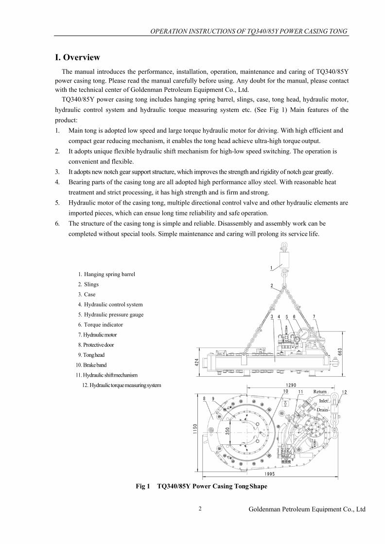
TQ340/85Y power casing tong includes hanging spring barrel, slings, case, tong head, hydraulic motor, hydraulic control system and hydraulic torque measuring system etc. (See Fig 1) Main features of the product:1. Main tong is adopted low speed and large torque hydraulic motor for driving. With high efficient and
compact gear reducing mechanism, it enables the tong head achieve ultra-high torque output.2. It adopts unique flexible hydraulic shift mechanism for high-low speed switching. The operation is
convenient and flexible.3. It adopts new notch gear support structure, which improves the strength and rigidity of notch gear greatly.4. Bearing parts of the casing tong are all adopted high performance alloy steel. With reasonable heat
treatment and strict processing, it has high strength and is firm and strong.5. Hydraulic motor of the casing tong, multiple directional control valve and other hydraulic elements are
imported pieces, which can ensue long time reliability and safe operation.6. The structure of the casing tong is simple and reliable. Disassembly and assembly work can be
completed without special tools. Simple maintenance and caring will prolong its service life.
1. Hanging spring barrel
2. Slings
3. Case
4. Hydraulic control system
5. Hydraulic pressure gauge
6. Torque indicator
7. Hydraulic motor
8. Protective door
9. Tong head
10. Brake band
11. Hydraulic shift mechanism
12. Hydraulic torque measuring system
Fig 1 TQ340/85Y Power Casing Tong Shape
Return
Inlet
Drain
OPERATION INSTRUCTIONS OF TQ340/85Y POWER CASING TONG
Goldenman Petroleum Equipment Co., Ltd3
II. Performance Parameters1. Applicable tube's diameter: ø114.3—ø339.7(41/2″—133/8″)
2. Opening dimensions: 350 mm
3. Nominal working pressure: 17.2 MPa (2500 psi)
4. Hydraulic pump flow: 110—170 L/min
5. Max torque of tong head: High gear: 12.5—14 kN.m
Low gear: 85—90 kN.m
6. Rotation speed of tong head: High gear: 30—45 rpm
Low gear: 3.2—5 rpm
7. Torque arm length: 1290 mm (50.8″)
8. Dimensions (L×W×H): 1995×1150×680 mm3
9. Weight: 1700 kg
10. Port:
High pressure inlet opening:
Low pressure return opening:
NPT1 or M30×1.5(C)
NPT11/4 or M42×2(D)
Drainage port: M18×1.5(C)
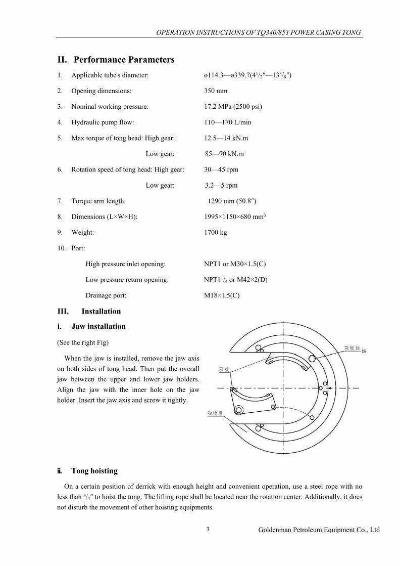
III. Installation
i. Jaw installation
(See the right Fig)
When the jaw is installed, remove the jaw axis on both sides of tong head. Then put the overall jaw between the upper and lower jaw holders. Align the jaw with the inner hole on the jaw holder. Insert the jaw axis and screw it tightly.
ii. Tong hoisting
On a certain position of derrick with enough height and convenient operation, use a steel rope with no less than 3/4″ to hoist the tong. The lifting rope shall be located near the rotation center. Additionally, it does not disturb the movement of other hoisting equipments.
Jaw holder
Jaw
Jaw axis

OPERATION INSTRUCTIONS OF TQ340/85Y POWER CASING TONG
Goldenman Petroleum Equipment Co., Ltd4
3t Single-sheaved block
3/4” Steel rope
Hanging spring cylinder
Slings
Tong
Torque measuring tension cylinder
One end of the lifting rope can be pulled through one pulley (with no less than 3 t load). Additionally, use a balance block (similar with the weight of tong) to take balance. It can also tie it on the derrick to form a dead line. Wherever the dead line is, it must use a hanging spring cylinder to compensate the downward movement distance in make-up of tong. (See Fig 2)
Fig 2 Hoisting Diagrammatic Sketch of Power Casing Tong

OPERATION INSTRUCTIONS OF TQ340/85Y POWER CASING TONG
Goldenman Petroleum Equipment Co., Ltd5
7/8” Steel rope
Torque measuring tension cylinder
iii. Tong Leveling
To ensure the tong teeth bite the casing tightly and notch gear of tong is operated normally, tong leveling is very important. After the tong is hoisted, just adjust the turnbuckles on the slings to complete leveling. Send the tong to the wellhead and rotate the 4 turnbuckles. Observe tong head until the tong teeth is aligned with the pipe. (See the following Fig)
iv. Tail rope connection
It is suggested to use 7/8″ or larger steel rope as the buffer tail rope of the tong. One end of the tail rope is connected with the torque measurer (tension cylinder), and the other end is fixed on an appropriate fixed leg. To ensure correct operation of torque measurer and torque indicator, the tail rope must be in 90 ° angle with the tong body. Furthermore, it shall be in the same level. (See the following Fig)

OPERATION INSTRUCTIONS OF TQ340/85Y POWER CASING TONG
Goldenman Petroleum Equipment Co., Ltd6
v. Hydraulic lifting cylinder connection
To align the upward and downward movement of tong with the casing conveniently, the hydraulic casing tong is equipped with hydraulic lifting cylinder. The lifting cylinder motor and the tong motor share a hydraulic source, and the action is controlled by a multiple directional control valve and hydraulic control non return valve.
The lifting cylinder is installed on the hanging spring cylinder. Connect the cylinder end with the shackle of hanging spring cylinder through a coupling fork. One end of the pipeline is connected with the inlet adapter of hydraulic cylinder. The other end is connected with the quick coupling on multiple directional control valve (See the following Fig)
vi. Hydraulic line connection
When the hydraulic power station does not work, use hydraulic line to connect the tong and power station. Inlet pipeline is 1" high-pressure hose, and return line is 11/4″ hose. Both are equipped with a self-styled quick change coupler. In installation, pay attention that two ends of the self-styled coupler shall be fully coupled to prevent cut-off valve in the coupler cannot be opened fully.

OPERATION INSTRUCTIONS OF TQ340/85Y POWER CASING TONG
Goldenman Petroleum Equipment Co., Ltd7
Gear shift hydraulic cylinder
Multiple directional control valves
Lifting hydraulic cylinder
Pressure gauge Hydraulic motor
IV. Operationi. Start-up
Start up the hydraulic station according to the operation instructions of hydraulic station operation manual. Before starting up the hydraulic station, release the overflow valve and check the oil volume in the oil tank. Check all hydraulic line fittings and ensure they all have been installed correctly.
Note: Before starting up the hydraulic station, make sure the protective door of power tong is closed, so as to ensure the safety of operator.
Start up the hydraulic station and let the hydraulic fluid flow for about 10 min. Adjust the overflow valve and raise the pressure to around 4 MPa. Set the shift lever at low gear, and operate the multiple directional control valves. Rotate the tong head slowly on both positive and negative directions.
Note: If the self-styled coupler of Hydraulic Hose is not connected in place, it will limit the hydraulic flow and result in pressure rising of hydraulic station system.
If the forward and reverse rotation is flexible and the jaw is installed correctly, the tong can be used for casing operation.
ii. Hydraulic Control System
The action of motor, gear shift hydraulic cylinder and lifting hydraulic cylinder in the tong can all be controlled by multiple directional control valves. The fluid pipe is parallel structure. Motor and hydraulic cylinder can be activated respectively and also simultaneously. (See Fig 3)
Fig 3 Hydraulic Schematics of TQ340/85Y Power Casing Tong

OPERATION INSTRUCTIONS OF TQ340/85Y POWER CASING TONG
Goldenman Petroleum Equipment Co., Ltd8
High gear Low gear
CaseDisc spring barrelGear shifting
hydraulic cylinder
iii. Direction and Speed ControlMultiple directional control valves can control the rotation direction and speed of tong head. Pull or push
the valve handle and the tong head is rotated in clockwise direction or anticlockwise direction, thus to achieve making-up or breaking out. As the spool of multiple unit valve has choking effect, the speed is in proportion to the distance between the central position of pushing or pulling of valve handle in forward and reverse rotation.
iv. High gear and low gear controlThe gear shifting mechanism is used to control the high speed and low speed rotation of tong. High gear
and low gear shifting is taken by flexible gear shifting mechanism. Operate the multiple directional control valve to extend the gear shifting hydraulic cylinder, and the clutch gear is up to hang together. The tong is in low gear. When the gear shifting hydraulic cylinder is extracted, the clutch gear is down to hang together and the tong is in high gear. (See the following Fig)
Note: High gear and low gear speed shifting shall be taken under the stop condition of motor.
v. Making-up1. Align the opening of tong head.2. Push the tong to wellhead and place it in working position.3. Close the protective door.4. Insert the direction changing pin into the “making-up” hole. (See the following Fig)
Correct pin position in making-up
5. Switch the variable speed gear to high gear.6. Push the handle of multiple unit valve forward slightly until the case coupler starts making up.7. When the coupler screw thread is connected correctly, push the handle of multiple unit valve forward
Making-up
OPERATION INSTRUCTIONS OF TQ340/85Y POWER CASING TONG
Goldenman Petroleum Equipment Co., Ltd9
completely until the tong head starts stopping rotation.8. Release the handle of multiple unit valve and switch to low gear.9. Make up the casing to appointed torque.10. Pull the handle of multiple unit valve backward slightly and rotate the tong head reversely. Release the
jaw and align the opening.11. Open the protective door and withdraw the tong from the casing.
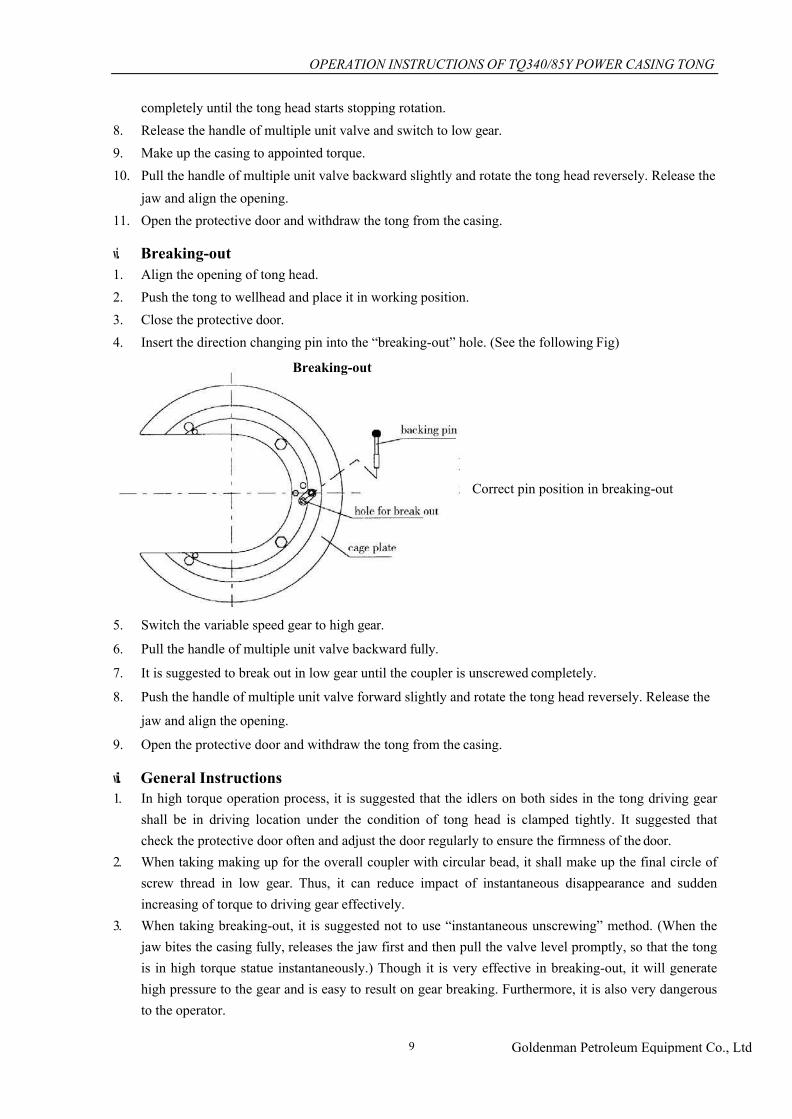
vi. Breaking-out1. Align the opening of tong head.2. Push the tong to wellhead and place it in working position.3. Close the protective door.4. Insert the direction changing pin into the “breaking-out” hole. (See the following Fig)
Correct pin position in breaking-out
5. Switch the variable speed gear to high gear.
6. Pull the handle of multiple unit valve backward fully.
7. It is suggested to break out in low gear until the coupler is unscrewed completely.
8. Push the handle of multiple unit valve forward slightly and rotate the tong head reversely. Release the
jaw and align the opening.
9. Open the protective door and withdraw the tong from the casing.
vii. General Instructions1. In high torque operation process, it is suggested that the idlers on both sides in the tong driving gear
shall be in driving location under the condition of tong head is clamped tightly. It suggested that check the protective door often and adjust the door regularly to ensure the firmness of the door.
2. When taking making up for the overall coupler with circular bead, it shall make up the final circle of screw thread in low gear. Thus, it can reduce impact of instantaneous disappearance and sudden increasing of torque to driving gear effectively.
3. When taking breaking-out, it is suggested not to use “instantaneous unscrewing” method. (When the jaw bites the casing fully, releases the jaw first and then pull the valve level promptly, so that the tong is in high torque statue instantaneously.) Though it is very effective in breaking-out, it will generate high pressure to the gear and is easy to result on gear breaking. Furthermore, it is also very dangerous to the operator.
Breaking-out
OPERATION INSTRUCTIONS OF TQ340/85Y POWER CASING TONG
Goldenman Petroleum Equipment Co., Ltd10
viii. Operation instruction in extremely cold weather
1. Read the preventive measures on operation in extremely cold weather in the hydraulic power station
manual.
2. Select gear and bearing lubricant that is suitable for the operation environment.
3. Select hydraulic fluid that is suitable for the operation environment.
4. In extremely code weather, after the hydraulic station is started up, it shall let the hydraulic fluid flow
about 20 min. Then start up the tong.
5. When cleaning the tong in extremely code weather, it shall dry the tong before lubricating.
V. MaintenanceIt is suggested to establish post responsibility system and maintenance plan to ensure the reliable using
of hydraulic power tong. It is suggested to take cleaning, lubrication and adjustment to the tong according to the following requirements, thus to prolong the service life of tong and ensure the safety of operator.
i. Cleaning
1. Before completing storage of the tong, it shall use petroleum-based cleaning agents to clean the tong
thoroughly.
2. After every tripping, it shall clean the slope surface of tong, jaw roller and pin etc. Additionally, coat a
thin layer of lubrication grease to ensure flexible rotation of roller and pin roll.
3. After every tripping, it shall clean the hydraulic cylinder and wipe the piston rod. Additionally, coat a
thin layer of lubrication grease.
4. It is suggested to disassemble the tong case regularly to clean the gears, rollers and bearings inside.
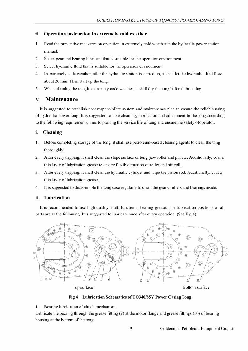
ii. Lubrication
It is recommended to use high-quality multi-functional bearing grease. The lubrication positions of all parts are as the following. It is suggested to lubricate once after every operation. (See Fig 4)
Top surface Bottom surface
Fig 4 Lubrication Schematics of TQ340/85Y Power Casing Tong
1. Bearing lubrication of clutch mechanismLubricate the bearing through the grease fitting (9) at the motor flange and grease fittings (10) of bearing housing at the bottom of the tong.

OPERATION INSTRUCTIONS OF TQ340/85Y POWER CASING TONG
Goldenman Petroleum Equipment Co., Ltd11
2. Bearing lubrication of duplex gear set
Lubricate the bearing through the grease fitting (5) of bearing housing on the top and at the bottom of the
tong.
3. Bearing lubrication of idler and duplex idler
Lubricate the bearing through the grease fitting (4, 6) of shaft end at the tong top.
4. Bearing lubrication of centering wheel
Lubricate the bearing through the grease fitting (2, 3) of shaft end at the tong top and tong bottom.
5. Roller and supporting roller lubrication on upper and lower panel
Coat a thin layer of lubrication grease on the surface of roller wheel and roller.
6. Lubrication of selector rod
Lubricate the rod through the grease fitting (8) of guide sleeve on the top of the tong.
7. Lubrication of disc spring barrel in hydraulic shift mechanism
Lubricate through the grease fitting (7) on the disc spring barrel.
8. Lubrication of bolt shaft of protective door
Lubricate through the grease fitting (1) of bolt shaft end on the top of the tong.
9. Lubrication of release link of protective door
Coat a thin layer of lubrication grease on the link and spring.
10. It is suggested to coat a thin layer of lubrication grease on the slope surface and surface of jaw roller
when the jaw is installed.
11. It is suggested to remove the observation plates on both sides of the main tong case. Coat lubrication
grease on clutch gear, gear sleeve and selector rod. Coat grease on teeth part of the driving gear.
iii. Adjustment
1. Bolt adjustment
During the using process of tong, the bolt may be worn, which will result loosing of door frame. Then, it can ensure using through adjusting the bolt shaft. (See the following Fig)
3/8” bolt
Left door Right door
Bolt shaft Bolt
Bolt shaft which is installed on the left door is an eccentric shaft. The flange board on the shaft top has 8
positioning holes, and it is fixed with the left door via a M10 bolt. When taking adjustment, remove the bolt
first and then rotate the bolt shaft to an appropriate angle. After aligning with the screw hole, screw up the
bolt.
OPERATION INSTRUCTIONS OF TQ340/85Y POWER CASING TONG
Goldenman Petroleum Equipment Co., Ltd12
Note: Correct door fitting is very important. It is conducive to correct gear meshing and reduction of transmission impact to ensure the safety of operation.
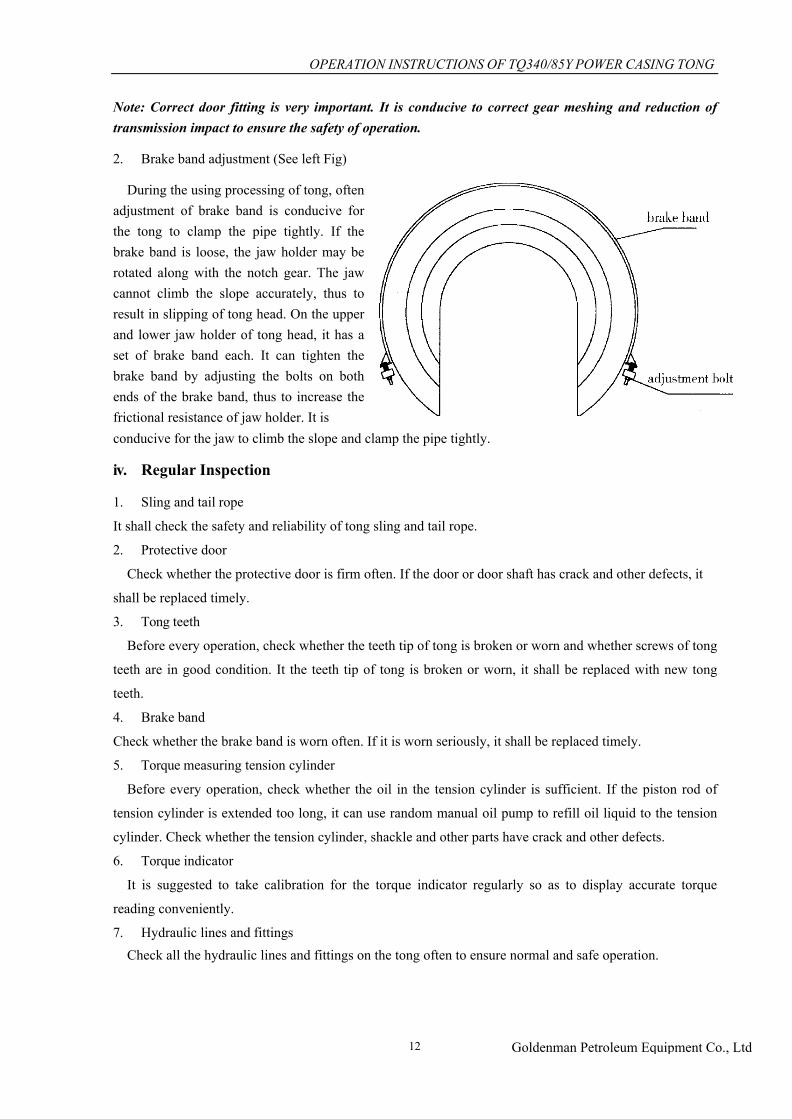
2. Brake band adjustment (See left Fig)
During the using processing of tong, often adjustment of brake band is conducive for the tong to clamp the pipe tightly. If the brake band is loose, the jaw holder may be rotated along with the notch gear. The jaw cannot climb the slope accurately, thus to result in slipping of tong head. On the upper and lower jaw holder of tong head, it has a set of brake band each. It can tighten the brake band by adjusting the bolts on both ends of the brake band, thus to increase the frictional resistance of jaw holder. It isconducive for the jaw to climb the slope and clamp the pipe tightly.
iv. Regular Inspection
1. Sling and tail rope
It shall check the safety and reliability of tong sling and tail rope.
2. Protective door
Check whether the protective door is firm often. If the door or door shaft has crack and other defects, it
shall be replaced timely.
3. Tong teeth
Before every operation, check whether the teeth tip of tong is broken or worn and whether screws of tong
teeth are in good condition. It the teeth tip of tong is broken or worn, it shall be replaced with new tong
teeth.
4. Brake band
Check whether the brake band is worn often. If it is worn seriously, it shall be replaced timely.
5. Torque measuring tension cylinder
Before every operation, check whether the oil in the tension cylinder is sufficient. If the piston rod of
tension cylinder is extended too long, it can use random manual oil pump to refill oil liquid to the tension
cylinder. Check whether the tension cylinder, shackle and other parts have crack and other defects.
6. Torque indicator
It is suggested to take calibration for the torque indicator regularly so as to display accurate torque
reading conveniently.
7. Hydraulic lines and fittingsCheck all the hydraulic lines and fittings on the tong often to ensure normal and safe operation.

OPERATION INSTRUCTIONS OF TQ340/85Y POWER CASING TONG
Goldenman Petroleum Equipment Co., Ltd13
VI. Fault Diagnosis and Troubleshootingi. Hydraulic system is overheating.
1. Too large press (overflow valve setting is too high.)
Solution: Adjust the overflow valve and adjust the liquid pressure.
2. Too high or too low oil viscosity
Solution: According to the using environment, change the hydraulic fluid.
3 Internal leakage of hydraulic system is too serious.
Solution: Replace the worn parts.
4. Oil leakage or blocking of hydraulic valve
Solution: Repair or replace the valve.
5. Oil level in the oil tank is too low and it cannot be cooled efficiently.
Solution: Refill oil.
6. Pump delivery is blocked.
Solution: Check overflow valve or throttle valve. Check whether the self - sealing coupling is connected
fully.
Note: Under high hydraulic pressure, it is prohibited to operate the pump continuously for a long period
with large displacement.
ii. Tong is run too slowly.
1. Suction line of the pump is blocked.
Solution: Clean the suction line.
2. Oil level in the oil tank is too low and the suction line is exposed out of the oil level.
Solution: Refill oil.
3. Suction line of the pump has air leak.
Solution: Repair
4. Pump rotation speed is too slow.
Solution: Check according to the manufacturer recommended speed value.
5. The pump or the tong has excessive wear.
Solution: According to the suggestion of manufacturer, replace the quick-wear parts.
6. Oil viscosity is too high and the pump cannot be started.
Solution: Replace the oil.
7. Hydraulic lines are blocked.
Solution: Check the lines .Check whether the self - sealing coupling is connected fully.
8. Overflow valve does not work.
Solution: Repair or replace the valve.

OPERATION INSTRUCTIONS OF TQ340/85Y POWER CASING TONG
Goldenman Petroleum Equipment Co., Ltd14
iii. Tong head does not have sufficient torque.
1. Overflow valve does not work.
Solution: Check whether the overflow valve is set too low, or is blocked, or has oil leak. Repair or replace the
valve.
2. Pump rotation speed is too slow.
Solution: Check according to the recommended speed value.
3. Oil viscosity is too high and the pump cannot be started.
Solution: Replace into proper oil.
4. The oil viscosity is too low and the system is overheating.
Solution: Replace into proper oil.
5. The tong motor is worn or damaged.
Solution: Repair or replace the motor.
6. Bearing or gear of transmission part is damaged and the resistance is increased.
Solution: Repair or replace damaged parts.
7. Hydraulic lines are blocked.
Solution: Check the lines .Check whether the self - sealing coupling is connected fully.
8. Oil liquid in the tension cylinder is insufficient. Torque indicator or connection pipeline has fault.
Solution: Refill oil liquid to the tension cylinder. Repair or replace damaged parts. Calibrate the torque indicator.
iv. Jaw cannot bite the pipe column.
1. Tong teeth are blunt.
Solution: Replace into new tong teeth.
2. The brake band is too loose and jaw cannot climb slope correctly.
Solution: Tighten the brake band.
3. Jaw roller is fractured or worn.
Solution: Replace the roller.
v. Tong head cannot be rotated.
1. The pressure is too low.
Solution: Adjust the overflow valve and adjust the liquid pressure.
2. Multiple directional control valve is damaged.
Solution: Repair or replace the valve.
3. Gear clutch mechanism is damaged.
Solution: Repair or replace the damaged parts.
vi. General instructions
It may result in fault of hydraulic system under the following conditions:
1. Oil changing frequency is insufficient or filtering is incorrect.
OPERATION INSTRUCTIONS OF TQ340/85Y POWER CASING TONG
Goldenman Petroleum Equipment Co., Ltd15
2. Correct hydraulic is not selected.
3. Sealing of hydraulic system has defects.
4. The understanding to hydraulic elements is not enough and the operation is improper.
VII. Storage Suggestions1. When storing the tong, it shall seal all liquid and gas ports to outside. Place the tong in a clean, dry
and ventilated place.
2. During the storing process, the tong shall be lubricated properly.
3. If the quick-wear parts are stored for a long period, rust preventing oil shall be coated on the surface
and the parts shall be placed in dry environment.
4. All seal components shall be stored in moisture-proof and anticorrosion sealed container.
5. All bearings must be lubricated and stored in boxes or contained without dust and moisture.
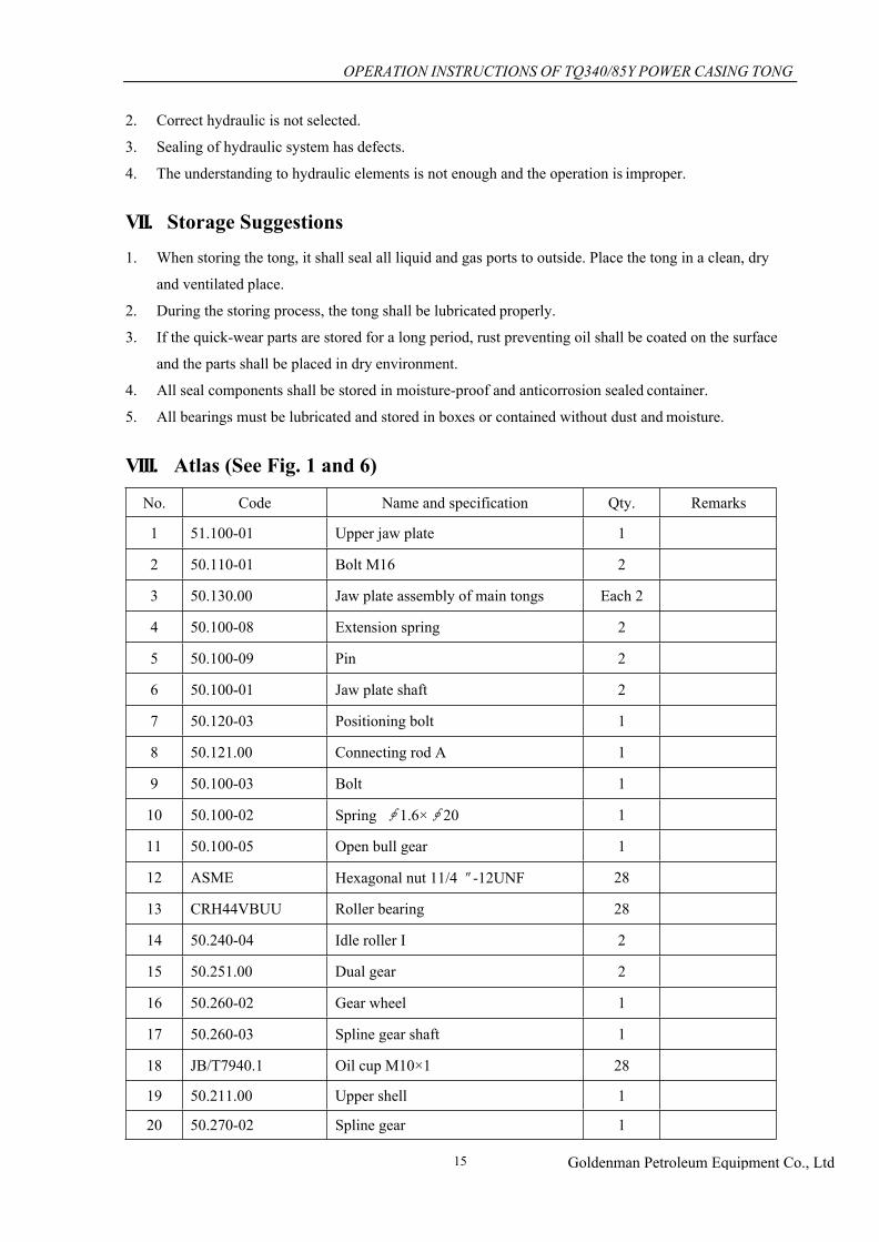
VIII. Atlas (See Fig. 1 and 6)
No. Code Name and specification Qty. Remarks
1 51.100-01 Upper jaw plate 1
2 50.110-01 Bolt M16 2
3 50.130.00 Jaw plate assembly of main tongs Each 2
4 50.100-08 Extension spring 2
5 50.100-09 Pin 2
6 50.100-01 Jaw plate shaft 2
7 50.120-03 Positioning bolt 1
8 50.121.00 Connecting rod A 1
9 50.100-03 Bolt 1
10 50.100-02 Spring ∮1.6×∮20 1
11 50.100-05 Open bull gear 1
12 ASME Hexagonal nut 11/4"-12UNF 28
13 CRH44VBUU Roller bearing 28
14 50.240-04 Idle roller I 2
15 50.251.00 Dual gear 2
16 50.260-02 Gear wheel 1
17 50.260-03 Spline gear shaft 1
18 JB/T7940.1 Oil cup M10×1 28
19 50.211.00 Upper shell 1
20 50.270-02 Spline gear 1
OPERATION INSTRUCTIONS OF TQ340/85Y POWER CASING TONG
Goldenman Petroleum Equipment Co., Ltd16
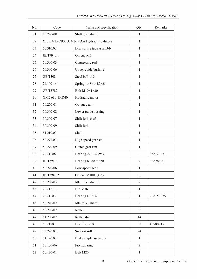
No. Code Name and specification Qty. Remarks
21 50.270-08 Shift gear shaft 1
22 YJ01140L-CB32B140N30AA Hydraulic cylinder 1
23 50.310.00 Disc spring tube assembly 1
24 JB/T7940.1 Oil cup M6 1
25 50.300-03 Connecting rod 1
26 50.300-06 Upper guide bushing 1
27 GB/T308 Steel ball ∮9 1
28 24.100-14 Spring ∮8×∮1.2×25 1
29 GB/T5782 Bolt M10×1×30 1
30 GM2-630-1HD40 Hydraulic motor 1
31 50.270-01 Output gear 1
32 50.300-08 Lower guide bushing 1
33 50.300-07 Shift fork shaft 1
34 50.300-09 Shift fork 1
35 51.210.00 Shell 1
36 50.271.00 High speed gear set 1
37 50.270-09 Clutch gear rim 1
38 GB/T288 Bearing 22213C/W33 2 65×120×31
39 JB/T7918 Bearing K68×76×20 4 68×76×20
40 50.270-06 Low-speed gear 1
41 JB/T7940.2 Oil cup M10×1(45°) 6
42 50.250-03 Idle roller shaft II 2
43 GB/T6170 Nut M36 1
44 GB/T283 Bearing NF314 1 70×150×35
45 50.240-02 Idle roller shaft I 2
46 50.230-02 Roller 32
47 51.230-02 Roller shaft 14
48 GB/T281 Bearing 1208 32 40×80×18
49 50.220.00 Support roller 24
50 51.120.00 Brake staple assembly 1
51 50.100-06 Friction ring 2
52 50.120-01 Bolt M20 1

OPERATION INSTRUCTIONS OF TQ340/85Y POWER CASING TONG
Goldenman Petroleum Equipment Co., Ltd17
No. Code Name and specification Qty. Remarks
53 50.120-02 Rear positioning sleeve 1
54 51.100-00 Lower jaw plate 1
55 50.110-02 Front positioning sleeve 2
56 GB/T276 Bearing 6206 4
57 51.220-01 Door shaft 2
58 51.220-02 Outer spacer 4
59 51.220-04 Door bolt shaft 1
60 51.221.00 Left door 1
61 51.223.00 Right door 1
62 51.224.00 Release link assembly 2
63 59.221.00 Velometer interface 1
64 Type A swaged hose fitting 32Ⅰ-630 (single 90°) 1
65 JB/ZQ4224 O ring 35×3.1 2
66 Type A swaged hose fitting 25Ⅲ-560(single 90°) 1
67 JB/ZQ4224 O ring 30×3.1 6
68 52.440-04A Return oil connector 1
69 NPT11/4″ self-sealing fast connector 1
70 52.420-01A Oil inlet connector 1
71 NPT1″ self-sealing fast connector 1
72 CTC106 Ranging device 1
73 JB8112-99 Breakout T-DW10 1
74 59.410-01 Motor connector G1-M36×2 2
75 Type A swaged hose fitting 25Ⅲ-440(single 90°) 2
76 YK-160 Torque gauge, 90 kN.m 1
77 YN-60 Hydraulic pressure gauge 1
78 DCV140/3-E2-S4-S1-S1-U1G12 Multi-way directional valve 1
79 Type A swaged hose fitting 8Ⅱ-440(single 90°) 1
80 JB/ZQ4224 O ring 11×1.9 6
81 SV10GA2-30/2 Hydraulic check valve 1
82 MK8G1.2/2 One-way throttle valve 1
83 Type A swaged hose fitting 8Ⅱ-420(single 90°) 2

OPERATION INSTRUCTIONS OF TQ340/85Y POWER CASING TONG
Goldenman Petroleum Equipment Co., Ltd18
Fig. 5 Structural Diagram of TQ340/85Y Hydraulic Casing Tongs

OPERATION INSTRUCTIONS OF TQ340/85Y POWER CASING TONG
Goldenman Petroleum Equipment Co., Ltd19
Fig. 6 General Drawing of TQ340/85Y Hydraulic Casing Tongs

IX. List of Recommended Spare Parts
No. Code Name Qty. for each set Using position Remarks
1 50.100-01 Jaw plate shaft 4
2 50.100-03 Bolt 2
3 50.151.00A Brake staple 4
4 50.100-06 Friction ring 2
Tong head
5 50.100-10 Tong tooth 4
6 50.131-02 Roller shaft 2
7 50.131-04 Tong head screw 8
8 50.134-02 Roller φ76 2
Jaw plate assembly
9 50.270-09 Clutch gear rim 1
10 50.300-07 Shift fork shaft 1
11 50.300-09 Shift fork 1
Shift mechanism
Bearing
1 JB/T7918 Bearing K68×76×20 4 Shift gear 68×76×20
2 GB/T281 Bearing 1208 32 Support roller wheel 40×80×18
3 CRH44VBUU Roller bearing 28 Tong head
Hydraulic parts
1 YJ01140L-CB32B140N30AAhydraulic cylinder 1 Shift
mechanism
2 HSGL01-63/35E-1110hydraulic cylinder (S=622) 1 Lifting
cylinder
3 Type A swaged hose fitting 8Ⅱ-420 (single 90°) 2
4 Type A swaged hose fitting 25Ⅲ-560(single 90°) 1
5 Type A swaged hose fitting 25Ⅲ-440(single 90°) 2
6 Type A swaged hose fitting 32Ⅰ-630(single 90°) 1
Hydraulic pipe
Seal
1 Washer 14 1
2 Washer 18 2
3 Washer 22 2
4 Washer 27 6
5
JB982
Washer 33 4
6 O ring 11×1.9 6
7 O ring 30×3.1 6
8
JB/ZQ4224
O ring 35×3.1 2
Hydraulic pipe
20