t&p chapter 13 - Óbudai egyetem bánki donát gépész ... · chapter 13/tooling ... broaches...
TRANSCRIPT

www.toolingandproduction.com Chapter 13/Tooling & Production 1
Metal RemovalCutting-Tool Materials
Metal Removal MethodsMachinability of Metals
Single Point MachiningTurning Tools and Operations
Turning Methods and MachinesGrooving and Threading
Shaping and Planing
Hole Making ProcessesDrills and Drilling Operations
Drilling Methods and MachinesBoring Operations and Machines
Reaming and Tapping
Multi Point MachiningMilling Cutters and OperationsMilling Methods and Machines
Broaches and BroachingSaws and Sawing
Abrasive ProcessesGrinding Wheels and OperationsGrinding Methods and Machines
Lapping and Honing
George Schneider, Jr. CMfgEProfessor Emeritus
Engineering TechnologyLawrence Technological University
Former ChairmanDetroit Chapter ONESociety of Manufacturing Engineers
Former PresidentInternational Excutive BoardSociety of Carbide & Tool Engineers
Lawrence Tech.- www.ltu.edu
Prentice Hall- www.prenhall.com
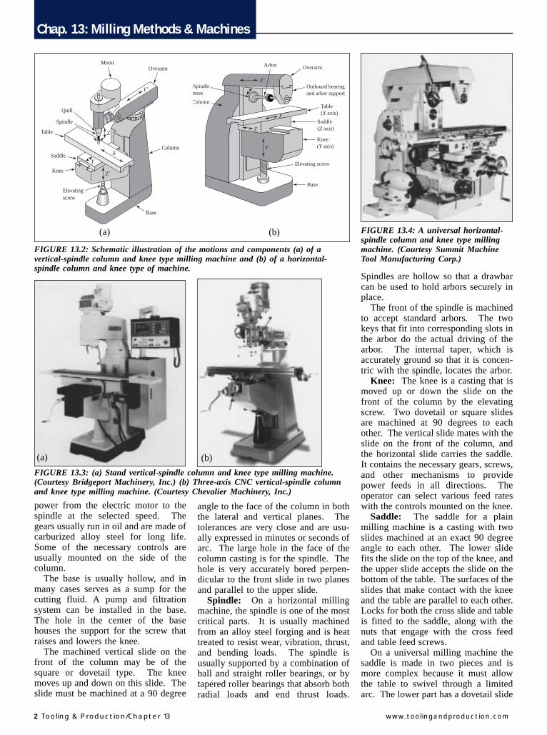
CHAPTER 13Milling Methodsand Machines13.1 IntroductionModern milling machines look muchthe same as they did 25 years ago.However, they now must cut superalloys, titanium, and high tensile steelsto closer tolerances and at faster ratesthen previously. To handle these re-quirements, the new milling machinesprovide higher horsepower, greaterstiffness, and wider speed and feedranges than before. In addition, moreaccurate lead screws, closer alignment,numerical control (NC) and computernumerical control (CNC) all result infaster work with better finishes andgreater accuracy than ever before at-tained. A modern CNC vertical mill-ing machine is shown in Figure 13.1
13.2 Types of Milling MachinesThe many types of milling machinesused in manufacturing have been
grouped into three general classes.• Column and Knee Machines• Bed Type Milling Machines• Special Purpose Machines
The common subtypes are also iden-tified and discussed.
13.2.1 Column and Knee MachinesColumn and knee milling machinesare made in both vertical and horizon-tal types. The schematic diagrams(Fig. 13.2a and Fig.13.2b) show bothtypes of machines. Versatility is a ma-jor feature of knee and column millingmachines. On a basic machine of thistype, the table, saddle, and knee can bemoved. Many accessories such as uni-versal vises, rotary tables, and dividingheads, further increase the versatilityof this type of machine.
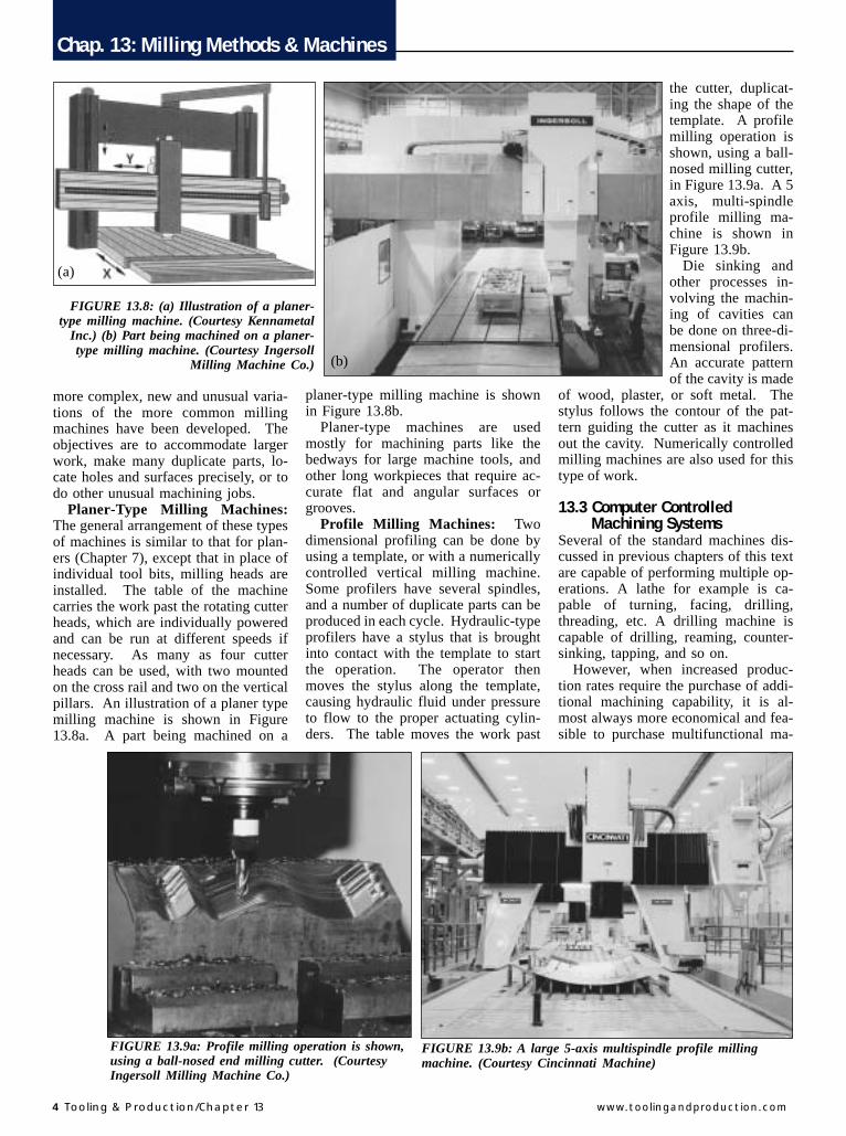
Regardless of whether the machineis of the vertical or horizontal type,several components on all column andknee milling machines are similar, ex-cept for size and minor variations be-cause of manufacturer’s preference.These similarities are described interms of general shape, geometric rela-tionship to the rest of the machine,function, and the material from whichthe components are made. Figure13.3a shows a standard vertical millingmachine and Figure 13.3b shows a 3axis CNC vertical milling machine
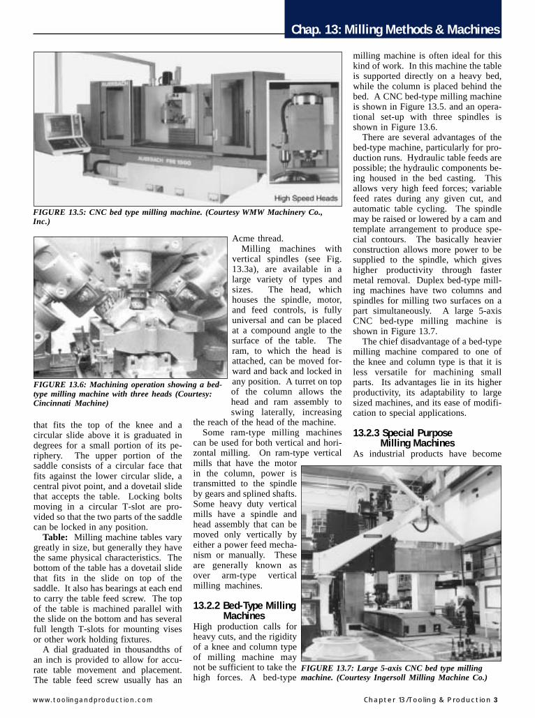
A universal Horizontal Column andKnee milling machine is shown inFigure 13.4.
Column: The column, which isusually combined with the base as asingle casting, is cast gray iron orductile iron. The column houses thespindle, bearings, and the necessarygears, clutches, shafts, pumps, andshifting mechanisms for transmitting
FIGURE 13.1: Modern CNC verticalmilling machine (Courtesy IngersollMilling Machine Co.)
Chap. 13: Milling Methods & Machines
2 Tooling & Production/Chapter 13 www.toolingandproduction.com
power from the electric motor to thespindle at the selected speed. Thegears usually run in oil and are made ofcarburized alloy steel for long life.Some of the necessary controls areusually mounted on the side of thecolumn.
The base is usually hollow, and inmany cases serves as a sump for thecutting fluid. A pump and filtrationsystem can be installed in the base.The hole in the center of the basehouses the support for the screw thatraises and lowers the knee.
The machined vertical slide on thefront of the column may be of thesquare or dovetail type. The kneemoves up and down on this slide. Theslide must be machined at a 90 degree
angle to the face of the column in boththe lateral and vertical planes. Thetolerances are very close and are usu-ally expressed in minutes or seconds ofarc. The large hole in the face of thecolumn casting is for the spindle. Thehole is very accurately bored perpen-dicular to the front slide in two planesand parallel to the upper slide.
Spindle: On a horizontal millingmachine, the spindle is one of the mostcritical parts. It is usually machinedfrom an alloy steel forging and is heattreated to resist wear, vibration, thrust,and bending loads. The spindle isusually supported by a combination ofball and straight roller bearings, or bytapered roller bearings that absorb bothradial loads and end thrust loads.
Spindles are hollow so that a drawbarcan be used to hold arbors securely inplace.
The front of the spindle is machinedto accept standard arbors. The twokeys that fit into corresponding slots inthe arbor do the actual driving of thearbor. The internal taper, which isaccurately ground so that it is concen-tric with the spindle, locates the arbor.
Knee: The knee is a casting that ismoved up or down the slide on thefront of the column by the elevatingscrew. Two dovetail or square slidesare machined at 90 degrees to eachother. The vertical slide mates with theslide on the front of the column, andthe horizontal slide carries the saddle.It contains the necessary gears, screws,and other mechanisms to providepower feeds in all directions. Theoperator can select various feed rateswith the controls mounted on the knee.
Saddle: The saddle for a plainmilling machine is a casting with twoslides machined at an exact 90 degreeangle to each other. The lower slidefits the slide on the top of the knee, andthe upper slide accepts the slide on thebottom of the table. The surfaces of theslides that make contact with the kneeand the table are parallel to each other.Locks for both the cross slide and tableis fitted to the saddle, along with thenuts that engage with the cross feedand table feed screws.
On a universal milling machine thesaddle is made in two pieces and ismore complex because it must allowthe table to swivel through a limitedarc. The lower part has a dovetail slide
OverarmMotor
Quill
Table
Saddle
Knee
Column
Base
Elevatingscrew
Spindle
Z ′
Y ′
Y
X
Z
OverarmArbor
Outboard bearingand arbor support
Table(X axis)
Saddle(Z axis)
Knee(Y axis)
Base
Elevating screw
Spindlenose
Column
Y
Z ′
Z
X
(a) (b)
FIGURE 13.2: Schematic illustration of the motions and components (a) of avertical-spindle column and knee type milling machine and (b) of a horizontal-spindle column and knee type of machine.
FIGURE 13.3: (a) Stand vertical-spindle column and knee type milling machine.(Courtesy Bridgeport Machinery, Inc.) (b) Three-axis CNC vertical-spindle columnand knee type milling machine. (Courtesy Chevalier Machinery, Inc.)
FIGURE 13.4: A universal horizontal-spindle column and knee type millingmachine. (Courtesy Summit MachineTool Manufacturing Corp.)
(b)(a)
Chap. 13: Milling Methods & Machines
www.toolingandproduction.com Chapter 13/Tooling & Production 3
that fits the top of the knee and acircular slide above it is graduated indegrees for a small portion of its pe-riphery. The upper portion of thesaddle consists of a circular face thatfits against the lower circular slide, acentral pivot point, and a dovetail slidethat accepts the table. Locking boltsmoving in a circular T-slot are pro-vided so that the two parts of the saddlecan be locked in any position.
Table: Milling machine tables varygreatly in size, but generally they havethe same physical characteristics. Thebottom of the table has a dovetail slidethat fits in the slide on top of thesaddle. It also has bearings at each endto carry the table feed screw. The topof the table is machined parallel withthe slide on the bottom and has severalfull length T-slots for mounting visesor other work holding fixtures.
A dial graduated in thousandths ofan inch is provided to allow for accu-rate table movement and placement.The table feed screw usually has an
Acme thread.Milling machines with
vertical spindles (see Fig.13.3a), are available in alarge variety of types andsizes. The head, whichhouses the spindle, motor,and feed controls, is fullyuniversal and can be placedat a compound angle to thesurface of the table. Theram, to which the head isattached, can be moved for-ward and back and locked inany position. A turret on topof the column allows thehead and ram assembly toswing laterally, increasing
the reach of the head of the machine.Some ram-type milling machines
can be used for both vertical and hori-zontal milling. On ram-type verticalmills that have the motorin the column, power istransmitted to the spindleby gears and splined shafts.Some heavy duty verticalmills have a spindle andhead assembly that can bemoved only vertically byeither a power feed mecha-nism or manually. Theseare generally known asover arm-type verticalmilling machines.
13.2.2 Bed-Type Milling MachinesHigh production calls forheavy cuts, and the rigidityof a knee and column typeof milling machine maynot be sufficient to take thehigh forces. A bed-type
milling machine is often ideal for thiskind of work. In this machine the tableis supported directly on a heavy bed,while the column is placed behind thebed. A CNC bed-type milling machineis shown in Figure 13.5. and an opera-tional set-up with three spindles isshown in Figure 13.6.
There are several advantages of thebed-type machine, particularly for pro-duction runs. Hydraulic table feeds arepossible; the hydraulic components be-ing housed in the bed casting. Thisallows very high feed forces; variablefeed rates during any given cut, andautomatic table cycling. The spindlemay be raised or lowered by a cam andtemplate arrangement to produce spe-cial contours. The basically heavierconstruction allows more power to besupplied to the spindle, which giveshigher productivity through fastermetal removal. Duplex bed-type mill-ing machines have two columns andspindles for milling two surfaces on apart simultaneously. A large 5-axisCNC bed-type milling machine isshown in Figure 13.7.
The chief disadvantage of a bed-typemilling machine compared to one ofthe knee and column type is that it isless versatile for machining smallparts. Its advantages lie in its higherproductivity, its adaptability to largesized machines, and its ease of modifi-cation to special applications.
13.2.3 Special Purpose Milling MachinesAs industrial products have become
FIGURE 13.5: CNC bed type milling machine. (Courtesy WMW Machinery Co.,Inc.)
FIGURE 13.6: Machining operation showing a bed-type milling machine with three heads (Courtesy:Cincinnati Machine)
FIGURE 13.7: Large 5-axis CNC bed type millingmachine. (Courtesy Ingersoll Milling Machine Co.)
Chap. 13: Milling Methods & Machines
4 Tooling & Production/Chapter 13 www.toolingandproduction.com
more complex, new and unusual varia-tions of the more common millingmachines have been developed. Theobjectives are to accommodate largerwork, make many duplicate parts, lo-cate holes and surfaces precisely, or todo other unusual machining jobs.
Planer-Type Milling Machines:The general arrangement of these typesof machines is similar to that for plan-ers (Chapter 7), except that in place ofindividual tool bits, milling heads areinstalled. The table of the machinecarries the work past the rotating cutterheads, which are individually poweredand can be run at different speeds ifnecessary. As many as four cutterheads can be used, with two mountedon the cross rail and two on the verticalpillars. An illustration of a planer typemilling machine is shown in Figure13.8a. A part being machined on a
planer-type milling machine is shownin Figure 13.8b.
Planer-type machines are usedmostly for machining parts like thebedways for large machine tools, andother long workpieces that require ac-curate flat and angular surfaces orgrooves.
Profile Milling Machines: Twodimensional profiling can be done byusing a template, or with a numericallycontrolled vertical milling machine.Some profilers have several spindles,and a number of duplicate parts can beproduced in each cycle. Hydraulic-typeprofilers have a stylus that is broughtinto contact with the template to startthe operation. The operator thenmoves the stylus along the template,causing hydraulic fluid under pressureto flow to the proper actuating cylin-ders. The table moves the work past
the cutter, duplicat-ing the shape of thetemplate. A profilemilling operation isshown, using a ball-nosed milling cutter,in Figure 13.9a. A 5axis, multi-spindleprofile milling ma-chine is shown inFigure 13.9b.
Die sinking andother processes in-volving the machin-ing of cavities canbe done on three-di-mensional profilers.An accurate patternof the cavity is made
of wood, plaster, or soft metal. Thestylus follows the contour of the pat-tern guiding the cutter as it machinesout the cavity. Numerically controlledmilling machines are also used for thistype of work.
13.3 Computer Controlled Machining SystemsSeveral of the standard machines dis-cussed in previous chapters of this textare capable of performing multiple op-erations. A lathe for example is ca-pable of turning, facing, drilling,threading, etc. A drilling machine iscapable of drilling, reaming, counter-sinking, tapping, and so on.
However, when increased produc-tion rates require the purchase of addi-tional machining capability, it is al-most always more economical and fea-sible to purchase multifunctional ma-
FIGURE 13.8: (a) Illustration of a planer-type milling machine. (Courtesy Kennametal
Inc.) (b) Part being machined on a planer-type milling machine. (Courtesy Ingersoll
Milling Machine Co.)
(a)
(b)
FIGURE 13.9a: Profile milling operation is shown,using a ball-nosed end milling cutter. (CourtesyIngersoll Milling Machine Co.)
FIGURE 13.9b: A large 5-axis multispindle profile millingmachine. (Courtesy Cincinnati Machine)

Chap. 13: Milling Methods & Machines
www.toolingandproduction.com Chapter 13/Tooling & Production 5
chines capable of quickchanges, simultaneousmachining, and automaticprocessing.
The term “Automation”was coined in the 1950’sand applied to devicesthat automatically loadand unload parts. Theterm is now accepted to cover, in addi-tion to loading and unloading, func-tions such as processing, measuringworkpiece size, adjusting a machine tomaintain size, and repeating ofworkpiece cycles.
Computer Controlled Manufactur-ing Systems discussed here will beMachining Centers and Flexible Ma-chining Systems.
13.3.1 Machining CentersMachining centers are designed andbuilt to provide for flexible manufac-turing. They can be used to machinejust a few parts or large productionruns. Programming can be relativelysimple and the use of ‘canned’ cyclesprovides a great deal of versatility. AnNC machining center by definition isable to perform milling, drilling, andboring cuts and has either indexing
turret tool holders or provides for auto-matic tool change. A tool holdermagazine is shown in Figure 13.10
Machining centers are built in eitherhorizontal or vertical configuration.
The relative merits of each will bediscussed briefly.
Horizontal Machines: Horizontalmachines tend to be advantageous forheavy box-shaped parts, such as gearhousings, which have many featuresthat need to be machined on the sidefaces. The horizontal machine easilysupports heavy workpieces of this type.If a rotary indexing worktable is added,four sides of the workpiece can bemachined without re-fixturing.
Pallet systems used to shuttle piecesin and out of the workstation tend to beeasier to design for horizontal ma-chines, where everything in front of themain column is open and accessible. Ahorizontal machining center with apallet shuttling system is shown inFigure 13.11.
Vertical Machines: Vertical ma-chining centers are often preferred forflat parts that must have through holes.Fixtures for these parts are more easilydesigned and built for a verticalspindle. Also, the thrust of the cutdeveloped in drilling or in millingpockets can be absorbed directly by thebed of the machine. The motions of a 3and 5-axis CNC vertical machiningcenter are shown in Figure 13.12.
The vertical machine is preferredwhere three-axis work is done on asingle face as in mold and die work.The weight of the head of a verticalmachine as it extends away from thecolumn, particularly on large ma-chines, can be a factor in maintainingaccuracy, as there may be some ten-dency for it to drop and lose accuracyand cause chatter. A vertical machin-ing center is shown in Figure 13.13and a machining center with an adjust-able head, tool change magazine and apallet system is shown in Figure 13.14
FIGURE 13.10: Preset machining center tools are stored in a toolholder magazine.(Courtesy Kennametal Inc.)
FIGURE 13.11:Horizontal machining
center with pallet shuttlingsystem. (Courtesy
Cincinnati Machine)
(a) (b)FIGURE 13.12: The motions of (a) a 3-axis CNC vertical machining center and (b)a 5-axis CNC vertical machining center. (Courtesy Kennametal Inc.)

Chap. 13: Milling Methods & Machines
6 Tooling & Production/Chapter 13 www.toolingandproduction.com
13.3.2 Flexible Machining SystemsFlexible machining systems employone or more machining centers, usu-ally along with other equipment, toproduce medium-volume workpieces.A workpiece-handling system is re-quired, and a central computer typi-cally controls the entire arrangement.A flexible machining system is shownin Figure 13.15.
Material Handling: Parts aremoved from storage and between ma-chine elements by means of one ofseveral different types of systems. Thematerial-handling system selectedmust be capable of routing any part toany machine in any order and also toprovide a bank of parts ahead of eachmachine to realize maximum produc-tivity. Parts are normally loaded andunloaded manually.
The various types of material-han-dling systems used include: automatedguided vehicles, towline systems, rollerconveyer systems, overhead conveyer
systems, monorails, cranes and robots.An FMS material-handling system isshown in Figure 13.16.
Control Systems: The computercontrols of flexible machining systemshave three functional levels
Master Control – The master controlmonitors and controls the entire sys-tem, including routing workpieces toappropriate machines, schedulingwork, and monitoring machine func-tions.
Direct Numerical Control – A DNCcomputer distributes appropriate pro-grams to individual CNC machinesand supervises and monitors their op-erations.
Element Control – The third andlowest level of control is
computer control of the machining
cycles of individual machines.
13.4 Milling Machine Attachments and AccessoriesMany accessories have been developedfor milling machines. Some are spe-cialized and can be used for only a fewoperations. Others, such as vises, ar-bors, and collets, are used in almost allmilling operations.
13.4.1 Special Milling HeadsSeveral types of special heads havebeen developed for use on horizontal orvertical milling machines. These ac-cessories increase the versatility of themachine. For example, a vertical headcan be attached to a conventional hori-zontal column and knee milling ma-
FIGURE 13.13: Transparent rendition of a verticalmachining center. (Courtesy Monarch Machine Tool)
FIGURE 13.14: Machining center with adjustable head, toolmagazine and pallet system (Courtesy Cincinnati Machine)
FIGURE 13.15: Flexible machiningsystem. (Courtesy Sandvik CoromantCo.)
FIGURE 13.16: FMS material-handling system. (Courtesy Giddings +Lewis LLC)

Chap. 13: Milling Methods & Machines
www.toolingandproduction.com Chapter 13/Tooling & Production 7
chine, greatly increasing its usefulness,especially in small shops with a limitednumber of machines.
Vertical Heads: Vertical heads aregenerally attached to the face of thecolumn or to the overarm of a horizon-tal milling machine. The head is asemi-universal type, which pivots onlyon the axis parallel to the centerline ofthe spindle, or it is fully universal.Fully universal heads can be set to cutcompound angles. Both types of headsare powered by the spindle of the mill-ing machine and accept standard ar-bors and collets. A universal millinghead attachment is shown in Figure13.17a.Figure 13.17b shows a univer-sal milling head attachment being usedon a horizontal milling machine.
Rack-Milling Attachment: Therack-milling attachment bolts to thespindle housing of the milling ma-chine. Its spindle is at a right angle tothe main spindle of the machine. Bothspur and helical racks can be milledwith this attachment, and it can also beused to mill worms. Some rack-mill-ing attachments have an outboard sup-port for the spindle, which makes itpossible to take heavier cuts.
Slotting Attachment: This attach-ment that is bolted to the column of ahorizontal milling machine can beswiveled 90 degrees in either directionfrom the vertical position. It is usedprimarily in toolmaking and prototypework for cutting keyways, internalsplines, and square or rectangular cavi-ties. The crank that actuates the recip-rocating slide is driven directly by thespindle, and the stroke is adjustable.
High Speed Attachment: Whenspindle speeds beyond the operating
range of the machine are necessary,high speed attachments can be placedon both horizontal and vertical millingmachines. A gear train is generallyused to step up the speed as much as 6to 1, which allows more efficient use ofsmall cutters.
13.4.2 Vises and FixturesIn all milling operations, the work isheld by fixtures, vises, or clampingarrangements. In most cases the workis held stationary in relation to thetable while it is being machined, butwork held in indexing heads and rotarytables can be moved in two planeswhile machining operations are inprogress.
Plain Vise: Plain milling vises (Fig.13.18a) are actuated by an Acmethreaded screw, and the movable jawmoves on either a dovetail or rectangu-lar slide. The vises are usually cast ofhigh grade gray cast iron or ductileiron and can be heat treated. Steel keysare attached in slots machined into thebottom of the vise, parallel with andperpendicular to, the fixed jaw to allowaccurate placement on the millingtable. The jaw inserts are usually heattreated alloy steel and are attached bycap screws. The jaw width and maxi-
mum opening classify vises of thistype. Cam-operated plain milling visesare widely used in production workbecause of the savings in time andeffort and the uniform clamping pres-sure that can be achieved.
Swivel-Base Vise: A swivel-basevise is more convenient to use than theplain vise, although it is somewhat lessrigid in construction. The base, whichis graduated in degrees, is slotted forkeys that align it with the T-slots in thetable. The upper part of the vise is heldto the base by T-bolts that engage acircular T-slot. The swivel-base vise,when used on a milling machine with asemi-universal head, makes it possibleto mill compound angles on aworkpiece.
Universal Vise: A universal vise(Fig. 13.18b) is used mostly intoolroom diemaking, and prototypework. The base of the vise is graduatedin degrees and held to the table by T-bolts. The intermediate part of the visehas a horizontal pivot upon which thevise itself can rotate 90 degrees. Be-cause there are several joints and piv-
FIGURE 13.17: (a) Universal millinghead attachment. (b) A universal millinghead attachment being used on ahorizontal milling machine. (CourtesyWMW Machinery Co., Inc.)
(a)
(b)
(a)
(b)
FIGURE 13.18: (a) A plain vise. (b) Auniversal vise, which is generally usedin a toolroom diemaking and protypework. (Courtesy Palmgren SteelProducts, Inc.)
Chap. 13: Milling Methods & Machines
8 Tooling & Production/Chapter 13 www.toolingandproduction.com
ots in the vise assembly, the universalvise is usually the least rigid of thevarious types of milling machine vises.
Angle Plates: Several types ofangle plates can be used to hold workor work holding fixtures for milling(Fig. 13.19). Plain angle plates areavailable in T-slotted or blank formand are usually strong iron castings.Adjustable angle plates may tilt in onedirection only or have a swivel base.They are very useful for millingworkpieces that are irregular in shape
and cannot be held easily in avise.
Holding fixtures, that are acombination of a simpleangle plate and a collet, aresometimes used to holdround or hexagonal work formilling. The collet-holdingfixture may be manually orair operated. Both fixturescan be bolted to the millingtable in the vertical or hori-zontal position or attached toan adjustable angle plate forholding workpieces at simpleor compound angles to thetable or other reference sur-face.
Indexing Heads: The in-dexing head, also known asthe dividing head (Fig.13.20), can be used on verti-cal and horizontal millingmachines to space the cutsfor such operations as mak-ing splines, gears, wormwheels, and many other partsrequiring accurate division.It can also be geared to thetable screw for helical mill-ing operations such as cutting
flutes in twist drills and making helicalgears.
Indexing heads are of the plain oruniversal type. Plain heads cannot betilted; universal heads can be tilted tothe vertical or any intermediate posi-tion. The spindle of the indexing headcan be fitted with a chuck, or withother work holding devices, includingcollets or a center. A cross-sectionalview of an indexing head is shown inFigure 13.21.
Most indexing heads have a worm
and wheel reduction ratio of 40:1, re-quiring 40 turns of the hand crank tomake the spindle revolve once. Whenthe necessary index plates are avail-able, all divisions up to and including50 can be achieved by plain indexing.For some numbers above 50, differen-tial indexing is necessary.
In recent years, programmable pre-cision indexers have become fairlycommon in shops doing work that re-quires accurate spacing of complexhole patterns on surfaces. The indexermay be mounted with the axis of thechuck vertical or horizontal, and insome cases the chuck may be replacedwith a specially made holding fixtureor a faceplate. If necessary, a tailstockmay be used to support the end of theworkpiece. The controller is capable ofstoring a series of programs, each ofwhich may incorporate as many as 100operational steps or positions.
Rotary Table: Rotary tables (Fig.13.22) are available in a wide range ofsizes and can be used on both verticaland horizontal milling machines.Most can also be clamped with the faceat a 90 degree angle to the surface ofthe milling machine table. The face ofthe rotary table has four or more T-slots and an accurately bored hole inthe center, which is concentric with theaxis about which the table rotates.
The base of the rotary table, which
FIGURE 13.19: Adjustable-angle tables can be tiltedin one or more directions to machine irregularlyshaped parts. (Courtesy Palmgren Steel Products,Inc.)
FIGURE 13.20: Indexing heads, also called dividingheads, can be used on vertical and horizontalmilling machines. (Courtesy Cincinnati Machine)
FIGURE 13.21:Cross-sectional
view of indexinghead. (Courtesy
CincinnatiMachine)
(a)
(b)FIGURE 13.22: (a) Rotary tables can beused on both vertical and horizontalmilling machines. (b) A rotary table,that can also be tilted. (CourtesyPalmgren Steel Products, Inc.)
Chap. 13: Milling Methods & Machines
www.toolingandproduction.com Chapter 13/Tooling & Production 9
houses the worm drive mechanism, isgraduated in degrees, and thehandwheel can be graduated in incre-ments as small as 5 minutes or 1/12 of1 degree. On some rotary tables anindex plate may be attached to thebase.
Rotary tables can also be geared tothe table feed screw. When set up inthis manner, the rotary table can beused to make plate cams and to gener-ate a number of other irregular shapes.
13.4.3 Arbors, Collets, and Tool HoldersSeveral basic types of arbors andcollets are used to hold milling cuttersand to transmit power from the spindleto the cutter. Regardless of type, theyare usually precisely made of alloysteel and heat treated for wear resis-tance and strength.
Arbors: Arbors for horizontal mill-ing machines (Fig. 13.23) are availablein three basic types: style A, style B,and style C. A draw bolt, that goesthrough the spindle of the machine,screws into the small end of the taperand draws the arbor tightly into thetapered hole in the milling machinespindle. Power is transmitted from thespindle to the arbor by two short keysthat engage with the slots on the flange
of the arbor.Style A arbors consist of the tapered
portion that fits the spindle, the shafton which the cutter or cutters fit, thespacers, and the nut. The shaft has akeyway along its entire length. Theoutboard end of the arbor has a pilotthat fits into a bronze bushing in theoutboard support of the milling ma-chine overarm (Fig. 13.2b). One ormore cutters can be mounted on thearbor, either adjacent to each other orseparated by spacers and shims. StyleA arbors are used primarily for lightand medium duty milling jobs.
Style B arbors are used for heavymilling operations, especially where itis necessary to provide support close toa milling cutter, such as in a straddlemilling operation. One or more bear-ing sleeves may be placed on the arboras near to the cutters as possible. Anoutboard bearing support is used foreach bearing sleeve on the arbor.
Style C arbors are used to hold anddrive shell end mills (Fig. 25.25b) andsome types of face milling cutters andrequire no outboard support. In somecases, they can also be fitted withadapters for mounting other types ofcutters.
Collets: On some vertical millingmachines the spindle is bored to accept
a collet that has a partly straight andpartly tapered shank. The collet issecured by a drawbar that is screwedinto a tapped hole in the back of thecollet and tightened from the top of thespindle. Some milling machine manu-facturers offer collet arrangements thatdo not need a drawbar. Collets of thistype can be closed with a lever-oper-ated cam or with a large locking nut.Figure 13.24a shows various sizecollets and Figure 13.24b shows anumber of tool holders includingcollets and a set-up fixture.
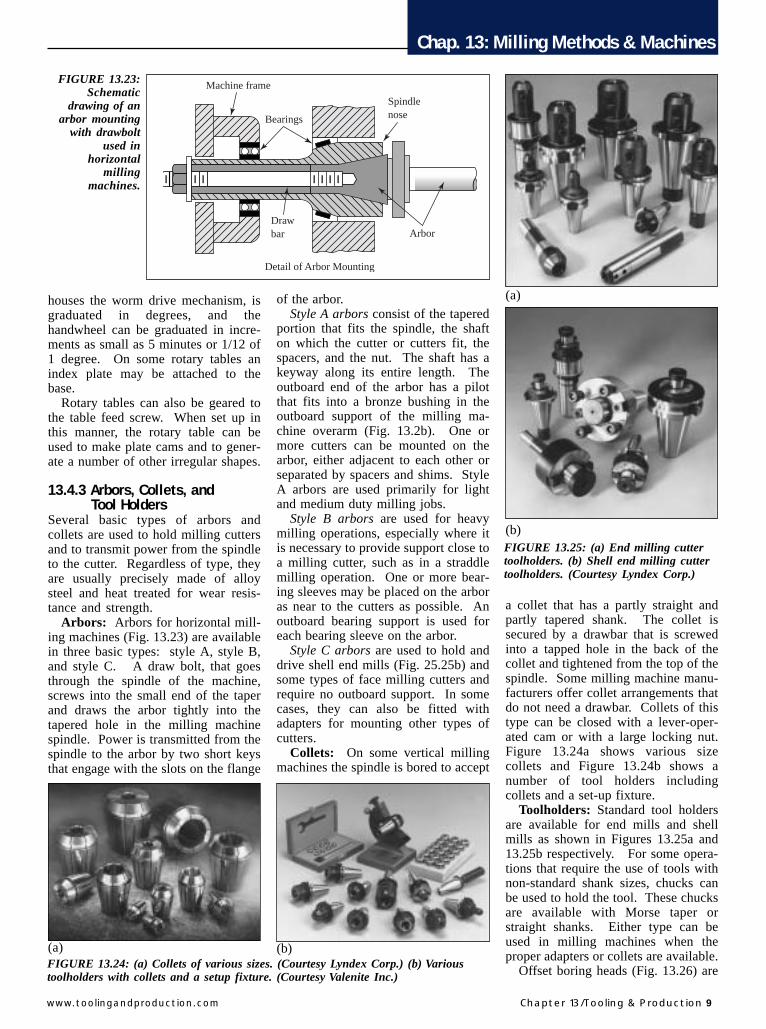
Toolholders: Standard tool holdersare available for end mills and shellmills as shown in Figures 13.25a and13.25b respectively. For some opera-tions that require the use of tools withnon-standard shank sizes, chucks canbe used to hold the tool. These chucksare available with Morse taper orstraight shanks. Either type can beused in milling machines when theproper adapters or collets are available.
Offset boring heads (Fig. 13.26) are
Machine frame
Drawbar Arbor
SpindlenoseBearings
Detail of Arbor Mounting
FIGURE 13.23:Schematic
drawing of anarbor mounting
with drawboltused in
horizontalmilling
machines.
FIGURE 13.24: (a) Collets of various sizes. (Courtesy Lyndex Corp.) (b) Varioustoolholders with collets and a setup fixture. (Courtesy Valenite Inc.)
(a) (b)
(a)
(b)FIGURE 13.25: (a) End milling cuttertoolholders. (b) Shell end milling cuttertoolholders. (Courtesy Lyndex Corp.)

Chap. 13: Milling Methods & Machines
10 Tooling & Production/Chapter 13 www.toolingandproduction.com
often used in vertical milling machinesfor boring, facing, chamfering, andoutside diameter turning operations.They are available with straight, Morsetaper, or standard milling machinetaper shanks and usually have threemounting holes for boring bars. Twoof the holes are usually parallel withthe centerline of the tool, and one isperpendicular to the centerline. Someboring heads have two adjustingmechanisms, and the movable slidecan be adjusted accurately in incre-ments of 0.0001 inch.
Flycutters can be used for facingoperations. The tools in cutters of thistype are adjusted so that both a rough-ing and finishing cut are taken in onepass.
13.5 Types of Milling OperationsMilling cutters are used either indi-vidually or in combinations to machinevarious surfaces as described belowand shown in Figure 13.27.
Plain Milling: Plain milling is theprocess of milling a surface that isparallel to the axis of the cutter andbasically flat. It is done on plain oruniversal horizontal milling machineswith cutters of varying widths thathave teeth only on the periphery.
Side Milling: For side milling, a
cutter that has teeth on the periphery,and on one or both sides, is used.When a single cutter is being used, theteeth on both the periphery and sidesmay be cutting. The machined sur-faces are usually either perpendicularor parallel to the spindle. Angle cut-ters can be used to produce surfacesthat are at an angle to the spindle forsuch operations as making externaldovetails or flutes in reamers.
Straddle Milling: In a typicalstraddle milling set-up (Fig. 13.27)two-side milling cutters are used. Astraddle milling operation is shown inFigure 13.28. The cutters are half-sideor plain side milling cutters, and havestraight or helical teeth. Stagger-toothside milling cutters can also be used.
The cutters cut on the inner sidesonly, or on the inner sides and theperiphery. If the straddle milling op-eration involves side and peripheral
cuts, the diameter of the two cuttersmust be exactly the same. When cut-ters with helical teeth are used, thehelix angles must be opposite.
Since straddle milled surfaces mustbe parallel to each other and are usu-ally held to close tolerances in terms ofwidth, the condition and size of thecollars and shims that separate thecutters are important. The arbor mustalso turn as true as possible to avoidcutting the workpiece undersize.
Usually, a combination of collarsand steel shims can be assembled toprovide the correct spacing betweencutters. For some production opera-tions, a special collar can be made fromalloy or medium-carbon steel, heattreated, and surface ground to length.The faces must be perpendicular to thebore and parallel to each other. Thecutters should be keyed to the arbor,and the outboard bearing supportsmust be placed as close to the cutters aspossible.
Gang Milling: In gang milling,three or more cutters are mounted onthe arbor, and several horizontal, verti-cal, or angular surfaces are machinedin one pass (Fig. 13.29). When mak-ing a gang milling set-up, several dif-ferent types of cutters can be used,depending on the job to be done. Cut-ters used for producing vertical or an-gular surfaces must be of the side-
FIGURE 13.26: Offset boring heads areoften used in milling machines forboring, facing, and chamferingoperations. (Courtesy BridgeportMachine, Inc.)
(a) Straddle milling (b) Form milling (c) Slotting (d) Slitting
FIGURE 13.27: Drawing of a milling cutter showing the difference between advanceper revolution (apr) and advance per tooth (apt).
FIGURE13.28:Conventionalor up-millingas compared oclimb or down-milling.
FIGURE 13.29:In gang milling
operations,horizontal,vertical, or
angularsurfaces aremachined in
one path.(Courtesy
SandvikCoromant Co.)
Chap. 13: Milling Methods & Machines
www.toolingandproduction.com Chapter 13/Tooling & Production 11
cutting type; plain milling cutters ofthe proper width can be used for hori-zontal surfaces. In some cases facemills with the teeth facing inward canbe used at one or both ends of the gangmilling set-up.
When only one wide plain helicalmilling cutter is used as part of a gangmilling set-up, the side thrust causedby that cutter should be directed towardthe spindle of the machine. If possible,interlocking cutters with opposite helixangles should be used to eliminate sidethrust and reduce the possibility ofchatter.
Because of the time and effort in-volved in setting up the milling ma-chine for gang milling, the process isused mainly for production work.Since all or almost all of the workpieceis being machined at one time, powerand rigidity are very desirable featuresin the machine being used. Everyeffort should be made to control vibra-tion, including the use of support barsthat are bolted to both the knee and theoutboard bearing support.
Form Milling: The number of par-allel surfaces and angular relationships
that can be machined by peripheralmilling is limited almost only by cutterdesign. Form cutters are expensive,but often there is no other satisfactorymeans of producing complex contoursas shown in Figure 13.27.
Slotting and Slitting Operations:Milling cutters of either the plain orside-cutting type are used for slottingand slitting operations (Fig.13.30a and13.30b). Slotting and Slitting are usu-ally done on horizontal milling ma-chines, but can also be done on verticalmills by using the proper adaptors andaccessories. Metal slitting cutters ofvarious diameters and widths are alsoused to cut slots. A number of identi-cal cutters can also be mounted on thesame arbor for cutting fins. When thethickness of the fins must be held to
close tolerances, spacers are usuallymachined and surface ground to pro-vide the necessary accuracy.
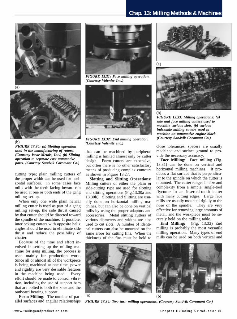
Face Milling: Face milling (Fig.13.31) can be done on vertical andhorizontal milling machines. It pro-duces a flat surface that is perpendicu-lar to the spindle on which the cutter ismounted. The cutter ranges in size andcomplexity from a simple, single-toolflycutter to an inserted-tooth cutterwith many cutting edges. Large facemills are usually mounted rigidly to thenose of the spindle. They are veryeffective for removing large amounts ofmetal, and the workpiece must be se-curely held on the milling table.
End Milling: (Fig. 13.32) Endmilling is probably the most versatilemilling operation. Many types of endmills can be used on both vertical and
(a)
(b)FIGURE 13.30: (a) Slotting operationused in the manufacturing of rotors.(Courtesy Iscar Metals, Inc.) (b) Slittingoperation to separate cast automotiveparts. (Courtesy Sandvik Coromant Co.)
FIGURE 13.31: Face milling operation.(Courtesy Valenite Inc.)
FIGURE 13.32: End milling operation.(Courtesy Valenite Inc.)
(a)
(b)FIGURE 13.33: Milling operations: (a)side and face milling cutters used tomachine various slots, (b) variousindexable milling cutters used tomachine an automotive engine block.(Courtesy Sandvik Coromant Co.)
FIGURE 13.34: Two turn milling operations. (Courtesy Sandvik Coromant Co.)
(a) (b)
Chap. 13: Milling Methods & Machines
12 Tooling & Production/Chapter 13 www.toolingandproduction.com
horizontal milling machines. Endmills are available in sizes rangingfrom 1/32 to 6 inches (for shell endmills) and in almost any shape needed.
Milling cutters can be used individu-ally or in pairs to machine various slots(Fig. 13.33a). Many milling cutterscan also be mounted onto an arbor toperform in a gang milling operation ofautomotive engine blocks as shown inFigure 25.33b
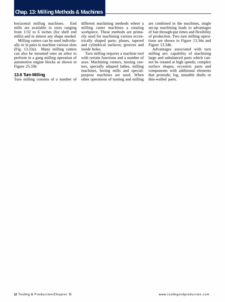
13.6 Turn MillingTurn milling consists of a number of
different machining methods where amilling cutter machines a rotatingworkpiece. These methods are prima-rily used for machining various eccen-trically shaped parts; planes, taperedand cylindrical surfaces; grooves andinside holes.
Turn milling requires a machine toolwith certain functions and a number ofaxes. Machining centers, turning cen-ters, specially adapted lathes, millingmachines, boring mills and special-purpose machines are used. Whenother operations of turning and milling
are combined in the machines, singleset-up machining leads to advantagesof fast through-put times and flexibilityof production. Two turn milling opera-tions are shown in Figure 13.34a andFigure 13.34b.
Advantages associated with turnmilling are: capability of machininglarge and unbalanced parts which can-not be rotated at high speeds; complexsurface shapes, eccentric parts andcomponents with additional elementsthat protrude; log, unstable shafts orthin-walled parts.