towards the enhancement of aircraft cargo compartment fire detection system certification using...
TRANSCRIPT

Towards the Enhancement of Aircraft Cargo CompartmentFire Detection System Certification using
Smoke Transport Modeling
Walt Gill and Jill Suo-Anttila
Fire Science and Technology Department
Sandia National LaboratoriesAlbuquerque, NM
David BlakeFire Safety Section
FAA Technical Center
International Fire and Cabin Safety Research ConferenceNovember 2004
Sandia is a multi-program laboratory operated by Sandia Corporation, a Lockheed-Martin Company, for the United States Department of Energy under Contract DE-AC04-94AL85000.

Sandia National Laboratories Team Members
• Experimental – David Blake, Walt Gill, and Jill Suo-Anttila
• Model Development – Jim Nelsen and Stefan Domino
• Graphical User Interface and Code Development– Carlos Gallegos
• Technical Support– Louis Gritzo, manager of the Fire Science and
Technology Department
Modeling Smoke Transport in Aircraft Cargo Compartments
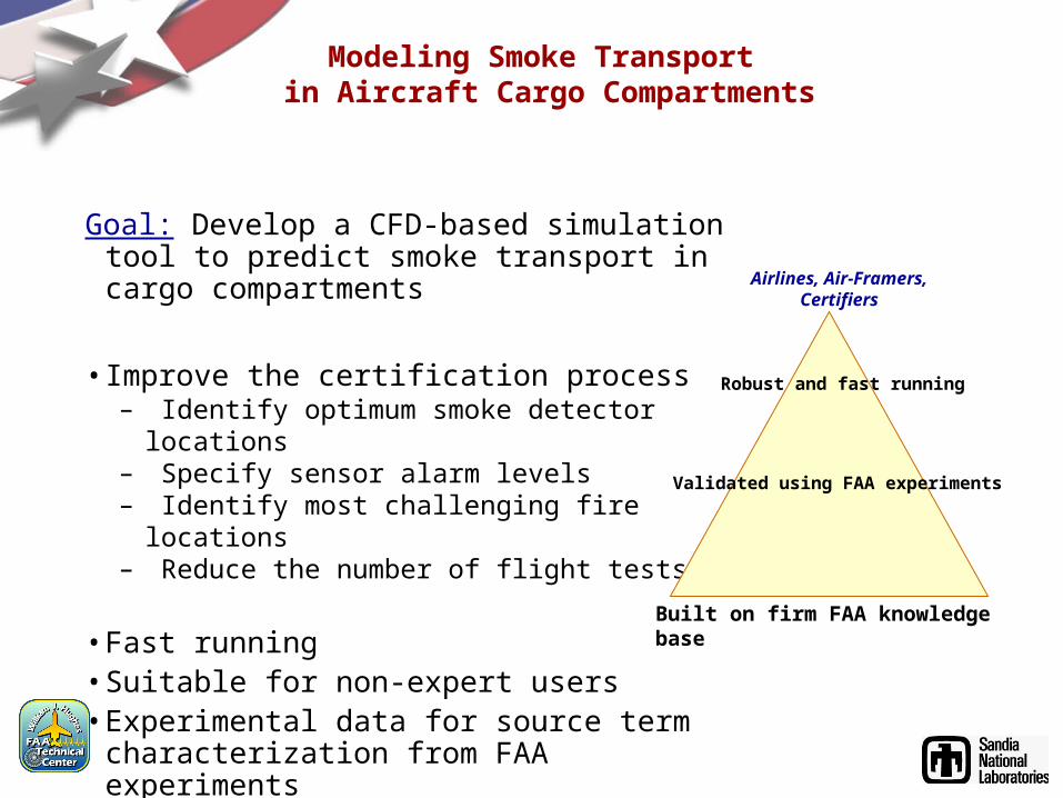
Goal: Develop a CFD-based simulation tool to predict smoke transport in cargo compartments
• Improve the certification process– Identify optimum smoke detector locations– Specify sensor alarm levels – Identify most challenging fire locations– Reduce the number of flight tests
• Fast running • Suitable for non-expert users • Experimental data for source term
characterization from FAA experiments• Validated using FAA full-scale experiments
Built on firm FAA knowledge base
Validated using FAA experiments
Airlines, Air-Framers, Certifiers
Robust and fast running
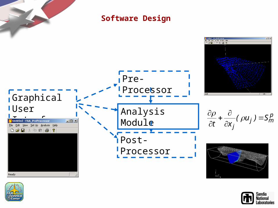
Software Design
Graphical User Interface
Pre-Processor
Analysis Module
Post-Processor
pmj
jS)u(
xt

Pre-Processor Overview
• Provide models for different aircraft
• Boeing 707, 727, 747, etc.
• User defined
• Capabilities
• Refine mesh
• Enter fire(s) location and type
• Enter ventilation velocities and locations
• Enter compartment temperature and pressure
• Add obstacles and recessed areas
• Instantaneous visual feedback

Running a Simulation Compartment and Mesh Specification
• Execute the Pre-Processor
• Select the type of compartment
– 707
– DC-10
– User Defined
• Input the dimensions
• Enter the mesh size - # of nodes
FAA_PreProcessor.lnk
custom
707 or DC-10

Running a Simulation Created 707 and DC-10 Meshes
• Automatically generated 707 mesh
• Curvature captured by mesh
• Right side of screen shows selected plane
• Automatically generated DC-10 mesh
• Internal view of compartment

Running a Simulation Recessed Area Specification
1. Advance to selected Y-plane
2. Select desired cells
3. Perform operation using buttons
1
2
3

Running a Simulation Obstacle Specification
Obstacle
Recessed Area

Running a Simulation Ventilation and Fire Specification
1. Select cells
2. Enter type of cell (inlet, outlet, fire) – cell colored to denote type
3. Use table to enter ventilation properties
4. Fire properties in file
31
2
Fire
Inlet
Outlet

Running a Simulation Mesh Refinement Specification
1. Select the plane for refinement
2. Use refinement tool
3. Enter level of refinement
12
3
Resulting Grid

Running a Simulation Running the Analysis Code
• Analysis - - - Run Analysis
• Status monitored on screen

Smoke Transport Analysis Code
• Curvature of compartment is resolved on grid
• HRR, MLR are time varying inputs (as measured in FAA experiments)
• Species tracking: presently soot, CO, and CO2 but addition of more or different species possible
• Simulation time = 1 hour per minute of real time
• Validated using FAA full-scale experiments
computational computational grid cell on wallgrid cell on wall
cellmass VMS /
cellener VQS /
180 240120600
12
10
8
6
4
2
0
Co
nce
ntr
atio
n C
O2,
CO
, HC
l, H
2O
(pa
rts
pe
r th
ou
san
d)
Time (seconds)
Co
nce
ntra
tion
All O
the
r Ga
ses
(pa
rts pe
r millio
n)
120
100
80
60
40
20
0
CO2
CO
H20
HCl
HCN
NO
ethylene
acteylene
methane
HCl
Temp (K)

Post-Processor
Allow users to manipulate data in a variety of ways • contour plots
• time history of field variables
• 3D smoke visualization in time
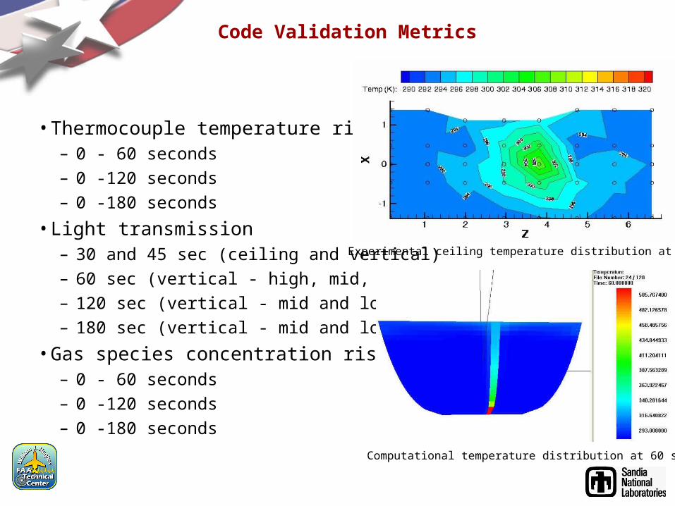
Code Validation Metrics
Insert most recent movie of temperature distribution
• Thermocouple temperature rise
– 0 - 60 seconds
– 0 -120 seconds
– 0 -180 seconds
• Light transmission– 30 and 45 sec (ceiling and vertical)
– 60 sec (vertical - high, mid, low)
– 120 sec (vertical - mid and low)
– 180 sec (vertical - mid and low)
• Gas species concentration rises– 0 - 60 seconds
– 0 -120 seconds
– 0 -180 seconds
Experimental ceiling temperature distribution at 60 sec
Computational temperature distribution at 60 sec
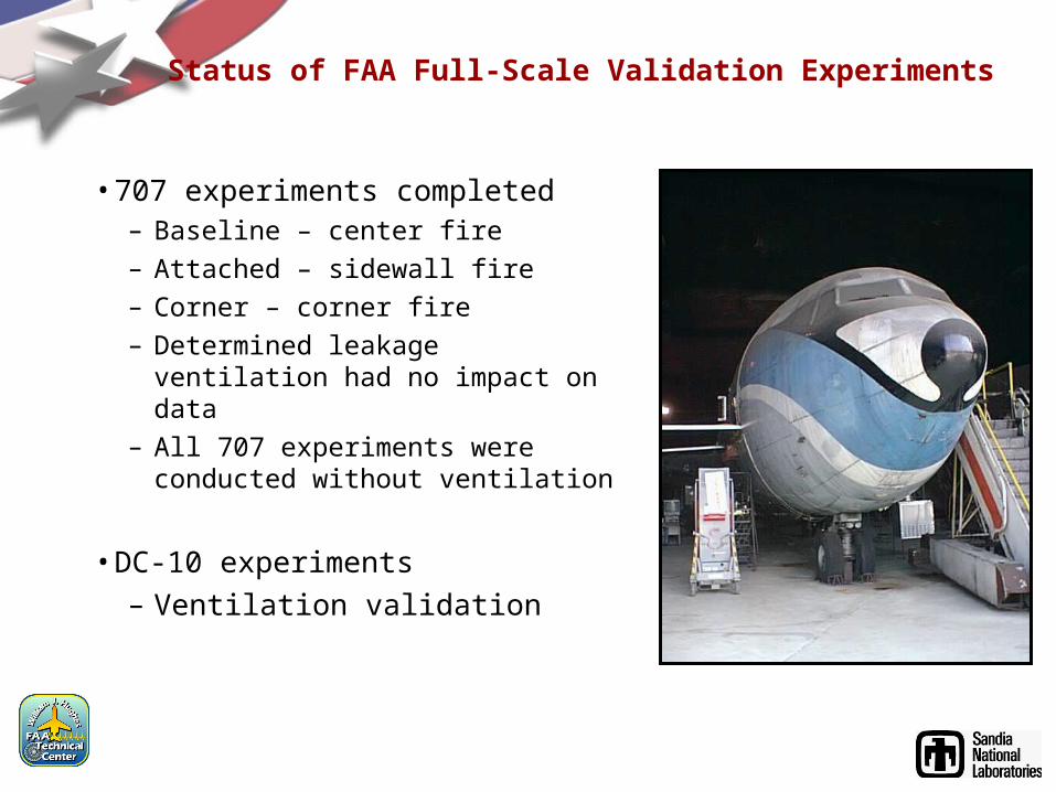
Status of FAA Full-Scale Validation Experiments
Insert most recent movie of temperature distribution
• 707 experiments completed– Baseline – center fire
– Attached – sidewall fire
– Corner – corner fire
– Determined leakage ventilation had no impact on data
– All 707 experiments were conducted without ventilation
• DC-10 experiments– Ventilation validation

707 Validation Simulations
Insert most recent movie of temperature distribution
• Interface described used to create mesh and run simulation
• Results and comparisons follow
Internal view (showing fire and recessed areas) of 707 computational domain
707 Baseline computational mesh
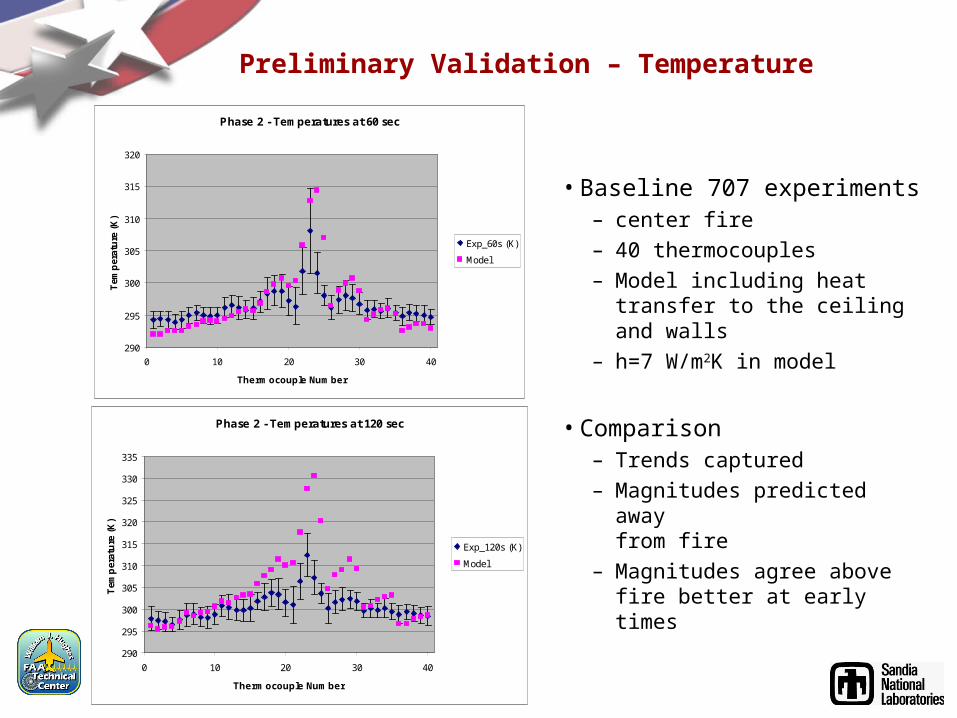
Preliminary Validation – Temperature
Insert most recent movie of temperature distribution
• Baseline 707 experiments– center fire– 40 thermocouples– Model including heat transfer to
the ceiling and walls – h=7 W/m2K in model
• Comparison– Trends captured– Magnitudes predicted away
from fire – Magnitudes agree above fire
better at early times
Phase 2 - Temperatures at 60 sec
290
295
300
305
310
315
320
0 10 20 30 40
Thermocouple Number
Tem
per
atu
re (
K)
Exp_60s (K)
Model
Phase 2 - Temperatures at 120 sec
290
295
300
305
310
315
320
325
330
335
0 10 20 30 40
Thermocouple Number
Tem
per
atu
re (
K)
Exp_120s (K)
Model

Preliminary Validation – Light Transmission
Insert most recent movie of temperature distribution
Phase 2 - Smokemeters at 30 sec
70
75
80
85
90
95
100
0 1 2 3 4 5 6 7
Smokemeter (Fwd, Mid, Aft, High, Mid, Low)
% L
igh
t T
ran
smis
sio
n
EXP_30s
Model
Phase 2 - Smokemeters at 45 sec
70
75
80
85
90
95
100
0 1 2 3 4 5 6 7
Smokemeter (Fwd, Mid, Aft, High, Mid, Low)
% L
igh
t T
ran
smis
sio
n
EXP_45s
Model
Phase 2 - Smokemeters at 60 sec
70
75
80
85
90
95
100
0 1 2 3 4 5 6 7
Smokemeter (Fwd, Mid, Aft, High, Mid, Low)
% L
igh
t T
ran
smis
sio
n
EXP_60s
Model
• Baseline 707 experiments– center fire– 6 smoke meters
• Comparison– Good agreement in trends and
magnitudes

• Continue validation of the smoke transport code– Finish code modifications– 707 validation comparisons– DC-10 validation comparison
• Release of code to small user community– Includes theory and users manual– Tutorial at FCS conference
• Revisions and final release of code (Summer ’05)
Future Activities

The Fourth Triennial The Fourth Triennial International Aircraft Fire and Cabin Safety International Aircraft Fire and Cabin Safety Research ConferenceResearch Conference