towards engineering isotropic behaviour of mechanical properties in thermally sprayed ceramic...
TRANSCRIPT

Available online at www.sciencedirect.com
202 (2008) 3643–3652www.elsevier.com/locate/surfcoat
Surface & Coatings Technology
Towards engineering isotropic behaviour of mechanical properties inthermally sprayed ceramic coatings
R.S. Lima ⁎, S.E. Kruger, B.R. Marple
National Research Council of Canada, 75 de Mortagne Blvd., Boucherville, QC, Canada J4B 6Y4
Received 15 October 2007; accepted in revised form 4 January 2008Available online 12 January 2008
Abstract
It is widely recognized by the scientific community that thermal spray coatings exhibit anisotropic behaviour of mechanical properties, e.g., theelastic modulus values of the coating in-plane (i.e., parallel to the substrate surface) or through-thickness (i.e., perpendicular to the substratesurface) will tend to be significantly different due to their anisotropic microstructures. This work shows that thermally sprayed ceramic coatingsmay exhibit isotropic mechanical behaviour similar to that of bulk materials even when exhibiting the typical anisotropic coating microstructure.Elastic modulus values on the in-plane and through-thickness directions were measured via Knoop indention and laser-ultrasonic techniques on acoating produced via flame spray (FS) using a nanostructured titania (TiO2) powder. No significant differences were found between the coatingdirections. In addition, four major cracks with similar lengths were observed originating near or at the corners of Vickers indentation impressionson the coating cross-section (i.e., a typical characteristic of bulk ceramics), instead of two major cracks propagating parallel to the substratesurface, which is normally the case for these types of coatings. It was observed by scanning electron microscopy (SEM) that coatings tended toexhibit an isotropic behaviour when the average length of microcracks within the coating structure oriented perpendicular to the substrate surfacewas about twice that of the microcracks aligned parallel to the substrate surface. Modelling, based on scalar crack densities of horizontal andvertical cracks, was also used to estimate when thermal spray coatings tend to exhibit isotropic behaviour.Crown Copyright © 2008 Published by Elsevier B.V. All rights reserved.
Keywords: Isotropic mechanical properties; Nanostructured titania (TiO2) powder; Processing; Microstructure; Thermal spray coatings
1. Introduction
1.1. Anisotropic microstructure of thermally sprayed coatings
Thermally sprayed coatings are formed by the impact,spreading, resolification and overlapping of fully molten and/orsemi-molten particles on a substrate surface. Consequently,thermally sprayed coatings typically exhibit a lamellar,anisotropic microstructure of randomly stacked splats andwell-defined horizontal splat boundaries. It is also possible toobserve coarse (globular) pores, which are associated withdefects in the structure, such as, the incomplete filling ofinterstices between previously deposited particles. For ceramiccoatings, in addition to these characteristics, it is common toobserve a network of intra- and inter-lamellar microcracks or
⁎ Corresponding author. Tel.: +1 450 641 5150; fax: +1 450 641 5105.E-mail address: [email protected] (R.S. Lima).
0257-8972/$ - see front matter. Crown Copyright © 2008 Published by Elsevier Bdoi:10.1016/j.surfcoat.2008.01.005
voids, which are normally generated due to imperfect splat-to-splat contact and quenching stress relaxation [1].
Due to this anisotropic microstructure, it is known thatthermally sprayed coatings tend to exhibit anisotropic char-acteristics of mechanical properties. For example, mechanicalproperties, such as elastic modulus (E), tend to exhibit differentvalues for the in-plane (parallel to the substrate surface) andthrough-thickness (perpendicular to the substrate surface)directions [2–4].
This phenomenon can be explained based on the shapes andorientation of pores and cracks. Inter-splat horizontal pores(voids) and intra-splat cracks may be considered as ellipsesexhibiting different aspect ratios, i.e., the ratio of the majoraxis over the minor axis, and regarded as pores parallel orperpendicular to the substrate surface, respectively. For example,a spherical void could be considered as an ellipse exhibiting aneccentricity value of zero or close to zero, whereas, a crack or aninter-splat pore could be considered as an ellipse that exhibits aneccentricity value equal to or near one. It is known that each
.V. All rights reserved.
3644 R.S. Lima et al. / Surface & Coatings Technology 202 (2008) 3643–3652
pancake-shaped splat is horizontally deformed/oriented withdimensions of approximately a few microns in thickness and tensof microns in diameter [5]. Due to this geometrical factor, thesurface area provided by horizontal inter-splat pores will tend tobe higher than that provided by the vertical intra-splat cracks[3,4,6]. As it is known that E values of bulk ceramics are loweredwhen the internal surface area of the material (i.e., porosity level)increases [7], it is then understandable why ceramic thermal spraycoatings tend to exhibit anisotropic E values.
The effect of the orientation and shape of cavities on the Evalues of materials was extensively discussed and modelled byKachanov et al. [8]. These models are very effective in helping tobetter understand the anisotropic character of complex structureslike thermal spray coatings. Kroupa et al. [9,10], based onthis previous work [8], adapted these mathematical models todescribe specifically the relationship between the microstruc-tural characteristics of thermally sprayed coatings with theanisotropy of the E values measured on the in-plane (Eip) andthrough-thickness (Ett) directions. The modeling is a function ofglobular pores, inter-splat horizontal pores/cracks and intra-splatcracks. According to the model, the material comprising thesplats is isotropic and homogeneous, exhibiting an elasticmodulus E0 and a Poisson's ratio ν0. Within the thermal spraycoating there are approximately N spherical (globular) pores ofradii Ri randomly distributed. The overall coating porosity (p) isgiven by:
p ¼ 1=Vð ÞXNi¼1
4=3ð ÞpR3i ð1Þ
where V is the representative volume element of the coating.According to the model, cracks do not contribute to porosity p. Afamily of approximately n3 circular and randomly distributedmicrocracks of radii r3 parallel to the substrate surface representsthe imperfect bonding between splats along the interfaces(boundaries). Their effect is given in terms of a scalar crackdensity ρ3:
q3 ¼ 1=Vð ÞXn3i¼1
r33i ð2Þ
A family of approximately n1 circular and randomly distri-buted microcracks of radii r1 perpendicular to the substratesurface represents the vertically oriented cracking. Their effect isgiven in terms of a scalar crack density ρ1:
q1 ¼ 1=Vð ÞXn1i¼1
r31i ð3Þ
In these equations, which try to represent a thermal spraymicrostructure, it is important to distinguish the difference betweenglobular spherical pores of radii Ri from microcracks of radii riperpendicular or parallel to the substrate surface. The resulting Evalues are given by two equations. For Eip, the equation is:
Eip ¼ E0
1þ p1−p
� �3 1�m0ð Þ 9þ5m0ð Þ
2 7�5m0ð Þ þ q11�p
� �8 1�m20ð Þ 1�3m0=8ð Þ
3 1�m0=2ð Þ
ð4Þ
For Ett, the equation is:
Ett ¼ E0
1þ p1�p
� �3 1�m0ð Þ 9þ5m0ð Þ
2 7�5m0ð Þ þ q31�p
� �16 1�m20ð Þ
3
ð5Þ
Based on these equations, the dependencies of the ratios ofthe elastic moduli Eip/E0 on ρ1 and Ett/E0 on ρ3 were plotted fordifferent values of porosity (p). It was observed that for thesame porosity levels (p) and scalar crack density values (ρ), theEip/E0 ratios were higher than those of the Ett/E0, i.e., themodeling was able to represent the anisotropic mechanicalbehaviour of thermal spray coatings.
1.2. Near-isotropic characteristics
Previous works have shown that ceramic thermal spraycoatings produced via air plasma spray (APS) and high velocityoxy-fuel (HVOF) from nanostructured and fused and crushed(F&C) powders may exhibit isotropic characteristics ofmechanical properties [11–13]. These near-isotropic coatingsexhibited at least some of the following characteristics:(i) absence of the typical lamellar microstructure, (ii) highdensity, (iii) extensive vertical intra-splat crack network, and(iv) tendency to exhibit four major cracks with similar lengthsemanating from or near the corners of the Vickers indentationimpression produced on the cross-section (when one of thediagonals of the Vickers indenter was positioned parallel to thesubstrate surface). Concerning this last characteristic (accordingto the best knowledge of the authors), this behaviour has beenobserved only for some coatings produced from nanostructuredagglomerated ceramic powders by APS [13] and HVOF [12].These coatings were also shown to exhibit improved wearresistance (however, their E values were not measured in thetwo directions to confirm the isotropic behaviour). Therefore,there seems to be some type of correlation between the nano-structural character of the feedstock with this type of isotopiccrack propagation behaviour of the coating, which may alsohave influenced the wear performance of this material.
1.3. Isotropic crack propagation
During an ongoing research project on the development oftitania (TiO2) coatings for sliding wear applications, it wasobserved that a coating developed by flame spray (FS) from ananostructured powder exhibited isotropic behaviour. DuringVickers indentation measurements on the cross-section, withone of the diagonals of the indenter aligned parallel to thesubstrate surface, four major cracks with similar lengths tendedto be observed originating at or near the corners of Vickersindentation impressions. This behaviour, which is typical of thatobserved in bulk ceramics [14], is shown in Fig. 1.
This is not a typical characteristic of ceramic thermal spraycoatings, which tend to exhibit two major cracks parallel to thesubstrate surface (in-plane direction) propagating from thecorners of the Vickers indentation impression, when the inden-tation is performed on the cross-section with one of thediagonals aligned parallel to the substrate surface [15]. This

Fig. 1. Isotropic behaviour— four major cracks with similar lengths originatingnear or at the corners of Vickers indentation impressions on the cross-section ofa flamesprayed nanostructured titania coating.
3645R.S. Lima et al. / Surface & Coatings Technology 202 (2008) 3643–3652
anisotropic crack propagation occurs predominantly due to thetypical microstructure of thermal spray coatings, with its well-defined splat boundaries, which provide easy crack propagationpaths.
Consequently, it is hypothesized that thermal spray coatingsexhibiting isotropic characteristics of crack propagation mayrespond differently to mechanical stresses, which may lead tonew types of applications and improved performances. Theevaluation of these coatings will also lead to a better under-standing of thermal spray microstructures. Therefore, theobjective of this work was to study in more detail the natureand origin of this type of isotropic behaviour of crack propagation.To achieve this objective, measurements of elastic modulusvalues on the in-plane and through-thickness directions of thecoating were carried out using a static, high strain, direct-contactand destructive technique (Knoop indentation), and a dynamic,low strain, non-contact and non-destructive technique (laser-ultrasonics). In addition, modeling of the elastic behaviour ofthermal spray coatingswas considered and carried out. The resultsof this research are intended to provide some additional guidanceon how to engineer isotropic ceramic thermal spray coatings.
2. Experimental procedure
2.1. Powder and thermal spraying
The nanostructured titania powder (TiCp2, Altair Nanoma-terials Inc., Reno, NV, USA) was deposited using an oxy-acetylene FS torch (Metco 6P-II, Sulzer Metco (US) Inc.,Westbury, NY, USA). Despite the fact that part of the originalnanostructure of the powder is partially destroyed duringthermal spraying, the expression “nanostructured coating” willbe used in this work to differentiate this type of coating fromthose produced from conventional powders. Powder particlesize distribution was evaluated using a laser diffraction particlesize analyzer (Beckman Coulter LS 13320, Beckman Coulter,Miami, FL, USA). The sprayed particles had their velocity and
temperature values measured by using an in-flight diagnostictool (Accuraspray, Tecnar Automation, Saint Bruno, QC,Canada), which is based on pyrometry and time-of-flightmeasurements. The particle detector was placed at the samespray distance as used when depositing the coatings, i.e., 10 cm.The coating was deposited onto 1.25 cm-thick low carbon steelsubstrates that had been grit-blasted before spraying. Coatingthickness was approximately 500–600 μm.
2.2. Microstructural characterization
The structural characteristics of the powder and the cross-section of the coating were evaluated by scanning electronmicroscopy (SEM) (Model S4700, Hitachi Instruments Inc.,Tokyo, Japan). In order to better preserve and reveal the truestructural features of the coating (cross-section), it was mountedin epoxy resin using vacuum impregnation and polished usingstandard metallographic procedures. The porosity of the coatingwas evaluated by using SEM and image analysis on the cross-section. A total of 10 pictures were taken (at 500×) to evaluateporosity levels. The powder and coating phase compositionswere determined by means of X-ray diffraction (XRD) using CuKα radiation (step: 0.05°/step time: 2.5 s) for values of 2θ inbetween 20° and 60°.
2.3. Microhardness values measured via Vickers indentation
For Vickers indentations (300 gf — 15 s), one diagonal ofthe Vickers indenter was positioned parallel to the substratesurface on the coating cross-section. A total of 10 indentationswere performed.
2.4. Elastic modulus values measured via Knoop indentation
Elastic modulus values were evaluated on the cross-sectionof the coating using Knoop indentations according to atechnique developed by Marshall et al. [16]. The Knoopindenter is a diamond ground to pyramidal form that produces adiamond shaped indentation having an approximate ratiobetween long (a) and short (b) diagonals of 7:1. The depth ofindentation is about 1/30 of its length. The Knoop techniqueemployed to measure E is based on the measurement of theelastic recovery of the dimensions of the Knoop indentationimpressions. The formula for determining the elastic modulus(E, in Pa) is:
E ¼ �aHð ÞbVaV� b
a
� � ð6Þ
where α is a constant (0.45), H is the Knoop hardness (in Pa),and a′ and b′ are the lengths of the major and minor diagonalsof the Knoop indentation impression.
During unloading, the elastic recovery reduces the length ofthe minor diagonal of the indentation impression (b′), while thelength of the major diagonal of the indentation impression (a′)remains relatively unaffected. The known major to minordiagonal ratio (7.11) of the indenter is compared to that of the

Fig. 2. Schematic of Eip and Ett measurements on the coating cross-section viaKnoop indentation.
3646 R.S. Lima et al. / Surface & Coatings Technology 202 (2008) 3643–3652
indentation impression. The extent of recovery depends on thehardness-to-modulus (H/E) ratio of the material being indented.
Therefore, as the measurement of E values via Knoopindentation is largely based on the elastic recovery of the minordiagonal (b′), this technique can be used to measure E values indifferent directions by simply aligning b′ with the desired Edirection. Consequently, the indentations were applied with theminor diagonal of the Knoop indenter positioned parallel to thesubstrate surface to measure Eip and perpendicular to thesubstrate surface to measure Ett, as shown in Fig. 2. A load of1000 gf, an indentation time of 15 s and a total of 10indentations per direction were applied for Knoop evaluation.
2.5. Elastic modulus values measured via laser-ultrasonics
The values of the elastic constants were measured on the in-plane and through-thickness directions of the coating via a laser-ultrasonics technique [17]. The ultrasonic waves are generatedby a Nd:YAG (third harmonic: 355 nm) laser pulse. For thethrough-thickness measurements the generation laser is focusedto a spot of about 3 mm in diameter on the back of the substrate(Fig. 3a), whereas, for the in-plane configuration the laser is
Fig. 3. Schematic of Eip and Ett measureme
focused in a line (∼200 μm×5 mm) on the coating surface(Fig. 3b). The detection is done by a long pulse Nd:YAG laser(1064 nm) focused on a region of about 1 mm in diameter on thecoating surface for the through-thickness measurement andwith a line geometry as in the generation for the in-planemeasurements. As the ultrasonic wave reaches the detection spotsurface, it modulates the detection light and a two-wave mixingGaAs interferometer is used to demodulate the collecteddetection light. Fig. 3 also shows signals obtained for in-planeand through-thickness measurements.
The elastic modulus value (E) of a material is directlyproportional to its density (ρ) and the velocity (v) of theultrasonic acoustic wave to the square travelling in the material(E=ρ · v2). By measuring the travel time of a longitudinal wavebouncing within the coating surface and substrate-coatinginterface (Fig. 3a) an elastic constant in the through-thicknessdirection can be calculated. Using the Cij notation for elasticconstants of anisotropic solids [18], the longitudinal modulus inthe through-thickness direction (direction 3) is given by:
C33 ¼ q2ett
� �2
ð7Þ
where e is the coating thickness and tt is the time delay betweenechoes bouncing in the coating (see Fig. 3a). For the in-planemeasurement, considering in-plane isotropy (C11=C22), thelongitudinal elastic constant is given by:
C11 ¼ qdtt
� �2
ð8Þ
where d and tt are respectively the travel distance and time ofarrival of the longitudinal waves, which are illustrated in Fig. 3b.
It is important to point out that a previous work indicated a“good” correlation between the E values measured via Knoopindentation and the laser-ultrasonics technique for APS andHVOF-sprayed TiO2 coatings produced from conventionalfused and crushed powders [19].
nts on the coating via laser-ultrasonics.
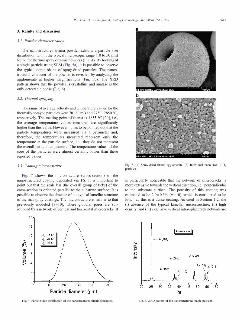
Fig. 5. (a) Spray-dried titania agglomerate. (b) Individual nano-sized TiO2
particles.
3647R.S. Lima et al. / Surface & Coatings Technology 202 (2008) 3643–3652
3. Results and discussion
3.1. Powder characterization
The nanostructured titania powder exhibits a particle sizedistribution within the typical microscopic range (10 to 50 μm)found for thermal spray ceramic powders (Fig. 4). By looking ata single particle using SEM (Fig. 5a), it is possible to observethe typical donut shape of spray-dried particles. The nanos-tructural character of the powder is revealed by analyzing theagglomerate at higher magnifications (Fig. 5b). The XRDpattern shows that the powder is crystalline and anatase is theonly detectable phase (Fig. 6).
3.2. Thermal spraying
The range of average velocity and temperature values for thethermally sprayed particles were 70–80 m/s and 2750–2850 °C,respectively. The melting point of titania is 1855 °C [20], i.e.,the average temperature values measured are significantlyhigher than this value. However, it has to be pointed out that theparticle temperatures were measured via a pyrometer and,therefore, the temperatures measured represent only thetemperature at the particle surface, i.e., they do not representthe overall particle temperature. The temperature values of thecore of the particles were almost certainly lower than thesereported values.
3.3. Coating microstructure
Fig. 7 shows the microstructure (cross-section) of thenanostructured coating deposited via FS. It is important topoint out that the scale bar (the overall group of ticks) of thecross-section is oriented parallel to the substrate surface. It ispossible to observe the absence of the typical lamellar structureof thermal spray coatings. The microstructure is similar to thatpreviously modeled [8–10], where globular pores are sur-rounded by a network of vertical and horizontal microcracks. It
Fig. 4. Particle size distribution of the nanostructured titania feedstock.
is particularly noticeable that the network of microcracks ismore extensive towards the vertical direction, i.e., perpendicularto the substrate surface. The porosity of this coating wasestimated to be 2.0±0.3% (n=10), which is considered to below, i.e., this is a dense coating. As cited in Section 1.2, the(i) absence of the typical lamellar microstructure, (ii) highdensity, and (iii) extensive vertical intra-splat crack network are
Fig. 6. XRD pattern of the nanostructured titania powder.

Fig. 7. Cross-section of the FS nanostructured coating.
3648 R.S. Lima et al. / Surface & Coatings Technology 202 (2008) 3643–3652
typical conditions previously observed for thermal spraycoatings that tended to exhibit isotropic behaviour of mechan-ical properties [11–13].
Fig. 8 shows the XRD pattern of the coating. A significantphase change from the powder is observed. The anatase phasepresent in the powder, was not detected in the coating (Fig. 6).Different phases were detected in the coating. The major phaseis crystalline rutile, which can be identified from the diffractionpeaks. Based on the characteristically amorphous humps foundin the ∼25–30° and ∼53–57° 2θ regions, it can be inferred thatamorphous titania is also present in the coating microstructure.The rutile phase probably originated from the melting andresolidification of the powder particles during thermal spraying,as observed by other authors [21,22], whereas, the amorphoustitania may have originated from the rapid cooling andresolidification of the molten particles that could have beenfast enough (in some cases) to prevent the formation of acrystalline phase from the melt, and/or semi-molten particlesthat did not fully transform from anatase to rutile phase duringthermal spraying. It has to be pointed out that the humpsobserved in Fig. 8 may also have been caused by an overlappingof peaks of the rutile, anatase and suboxide phases of titanium.
Fig. 8. XRD pattern of the nanostructured titania coating.
3.4. Vickers microhardness
The Vickers microhardness number (300 gf) of the coating is862±20 (n=10), which is within the values typically reportedfor titania thermal spray coatings, i.e., ∼800–900 [23].
3.5. Elastic modulus
The values of E measured via Knoop indentation and laser-ultrasonics on the in-plane and through-thickness directions ofthe FS nanostructured coating are listed in Table 1. The valuesof E measured via Knoop indentation in both directions are notstatistically different.
The E values measured via laser-ultrasonics technique agreewith the results obtained via Knoop indentation, i.e., the E valueson the in-plane and through-thickness directions tend to besimilar. The average Eip/Ett ratios measured via Knoop indenta-tion and laser-ultrasonics are 0.99 and 0.92, respectively. This isan important result because these two techniques, which areexhibiting the same isotropic trend, are totally different in theirapproaches to measure E values, i.e., static, high strain, direct-contact and destructive mode (Knoop) and dynamic, low strain,non-contact and non-destructive mode (laser-ultrasonics).
In early work, isotropic and homogeneous bulk ceramicmaterials were employed to model and develop crack propaga-tion behaviour on the elastic/plastic field of sharp indenters(e.g., Vickers) [24]. The isotropic elastic modulus behaviourand homogenous microstructures of these materials typicallyproduce a crack pattern of two half-penny cracks represented onthe surface as four major cracks with similar lengths propagat-ing from or near the corners of the Vickers indentationimpression [14,24]. Typical materials that are known for theiranisotropic E values, such as thermal spray coatings [2–4], tendto exhibit two major cracks parallel to the substrate surfacepropagating from the corners of the Vickers indentationimpression, when the indentation is performed on the cross-section with one of the diagonals aligned parallel to thesubstrate surface [15,25]. This anisotropic crack propagationoccurs predominantly due to the well-defined lamellar bound-aries, which provide less resistant crack propagation paths.Therefore, the crack propagation behaviour demonstrated by theFS nanostructured coating (Fig. 1) is definitely associated withthe isotropic E values observed for this coating.
The differences in the absolute E values obtained by the twotechniques (Table 1) are probably related to the microstructureof these ceramic thermal spray coatings and the nature of thetwo techniques. It is known that under tensile or compressivestresses the microcracks and pores of thermal spray coatings
Table 1Elastic modulus values measured via Knoop indentation and laser-ultrasonics onthe in-plane and through-thickness directions of the FS nanostructured coating
Eip (Knoop) Ett (Knoop) Eip (laser) Ett (laser)
(GPa) (GPa) (GPa) (GPa)
n=10 n=10 n=10 n=3
159±19 161±18 120±10 130±15
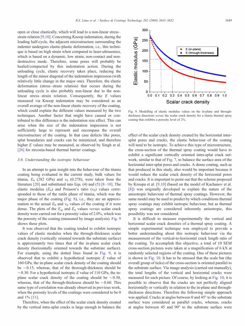
Fig. 9. Modelling of elastic modulus values on the in-plane and through-thickness directions versus the scalar crack density for a titania thermal spraycoating that exhibits a porosity level of 2%.
3649R.S. Lima et al. / Surface & Coatings Technology 202 (2008) 3643–3652
open or close elastically, which will lead to a non-linear stress–strain relation [9,10]. Concerning Knoop indentation, during theloading half-cycle, the adjacent microstructure surrounding theindenter undergoes elastic-plastic deformation, i.e., this techni-que is based on high strain when compared to laser-ultrasonics,which is based on a dynamic, low strain, non-contact and non-destructive mode. Therefore, some pores will probably behealed/compacted by this indentation action. During theunloading cycle, elastic recovery takes place, reducing thelength of the minor diagonal of the indentation impression (withrelatively little change in the major one). Therefore, the elasticdeformation (stress–strain relation) that occurs during theunloading cycle is also probably non-linear due to the non-linear stress–strain relation. Consequently, the E valuesmeasured via Knoop indentation may be considered as anoverall average of the non-linear elastic recovery of the coating,which could explain the different values measured by the twotechniques. Another factor that might have caused or con-tributed to this difference is the indentation size effect. This canarise when the size of the indentation impression is notsufficiently large to represent and encompass the overallmicrostructure of the coating. In that case defects like pores,splat boundaries and cracks can be minimized, and thereforehigher E values may be measured, as observed by Singh et al.[26] for zirconia-based thermal barrier coatings.
3.6. Understanding the isotropic behaviour
In an attempt to gain insight into the behaviour of the titaniacoating being evaluated in the current study, bulk values fortitania, E0 (282 GPa) and ν0 (0.278), were taken from theliterature [20] and substituted into Eqs. (4) and (5) [8–10]. Theelastic modulus (E0) and Poisson's ratio (ν0) values corre-sponded to those of the rutile phase of titania, which was themajor phase of the coating (Fig. 8), i.e., they are an approxi-mation to the actual E0 and ν0 values of the coating if it weredense. The plots of the Eip and Ett values versus scalar crackdensity were carried out for a porosity value of 2.0%, which wasthe porosity of the coating (measured by image analysis). Fig. 9shows these plots.
It was observed that the coating tended to exhibit isotropicvalues of elastic modulus when the through-thickness scalarcrack density (vertically oriented towards the substrate surface)is approximately two times that of the in-plane scalar crackdensity (horizontally oriented towards the substrate surface).For example, using the dotted lines found in Fig. 9, it isobserved that to exhibit a hypothetical isotropic E value of160 GPa, the in-plane scalar crack density of the coating shouldbe ∼0.15, whereas, that of the thorough-thickness should be∼0.30. For a hypothetical isotropic E value of 110 GPa, the in-plane scalar crack density of the coating should be ∼0.30,whereas, that of the through-thickness should be ∼0.60. Thissame type of correlation was already observed in previous work,when the porosity levels of the coatings were considered to be 0and 1% [11].
Therefore, when the effect of the scalar crack density createdby the vertical intra-splat cracks is large enough to balance the
effect of the scalar crack density created by the horizontal inter-splat pores and cracks, the elastic behaviour of the coatingwill tend to be isotropic. To achieve this type of microstructure,the cross-section of the thermal spray coating would have toexhibit a significant vertically oriented intra-splat crack net-work, similar to that of Fig. 7, to balance the surface area of thehorizontal inter-splat pores and cracks. A dense coating, such asthat produced in this study, also would be important because itwould reduce the scalar crack density of the horizontal poresand cracks. It is important to point out that the scheme proposedby Kroupa et al. [9,10] (based on the model of Kachanov et al.[8]) was originally developed to explain the nature of theanisotropic behaviour of thermal spray coatings. However, thesame model may be used to predict by which conditions thermalspray coatings may exhibit isotropic behaviour, but as thermalspray coatings are considered inherently anisotropic, thispossibility was not considered.
It is difficult to measure experimentally the vertical andhorizontal scalar crack densities of a thermal spray coating. Asimple experimental technique was employed to provide abetter understanding about this isotropic behaviour via themeasurement of the vertical-to-horizontal crack length ratio ofthe coating. To accomplish this objective, a total of 10 SEMcross-section pictures were taken at a magnification of 6 kX atrandomly selected regions of the coating. One of these picturesis shown in Fig. 10. It has to be stressed that the scale bar (theoverall group of ticks) of the cross-section is oriented parallel tothe substrate surface. Via image analysis (carried out manually),the total lengths of the vertical and horizontal cracks weremeasured for each picture. Of course, by looking at Fig. 10, it ispossible to observe that the cracks are not perfectly alignedhorizontally or vertically in relation to the in-plane and through-thickness directions. Therefore the following simple approachwas applied. Cracks at angles between 0 and 45° to the substratesurface were considered as parallel cracks, whereas, cracksat angles between 45 and 90° to the substrate surface were
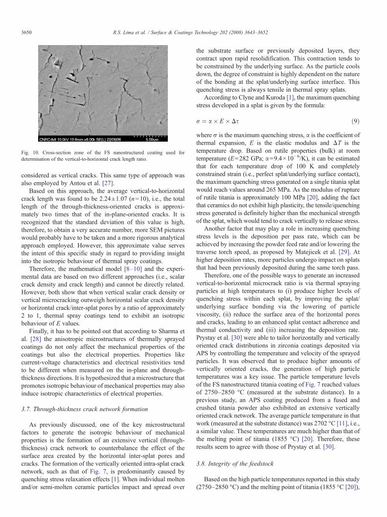
Fig. 10. Cross-section zone of the FS nanostructured coating used fordetermination of the vertical-to-horizontal crack length ratio.
3650 R.S. Lima et al. / Surface & Coatings Technology 202 (2008) 3643–3652
considered as vertical cracks. This same type of approach wasalso employed by Antou et al. [27].
Based on this approach, the average vertical-to-horizontalcrack length was found to be 2.24±1.07 (n=10), i.e., the totallength of the through-thickness-oriented cracks is approxi-mately two times that of the in-plane-oriented cracks. It isrecognized that the standard deviation of this value is high,therefore, to obtain a very accurate number, more SEM pictureswould probably have to be taken and a more rigorous analyticalapproach employed. However, this approximate value servesthe intent of this specific study in regard to providing insightinto the isotropic behaviour of thermal spray coatings.
Therefore, the mathematical model [8–10] and the experi-mental data are based on two different approaches (i.e., scalarcrack density and crack length) and cannot be directly related.However, both show that when vertical scalar crack density orvertical microcracking outweigh horizontal scalar crack densityor horizontal crack/inter-splat pores by a ratio of approximately2 to 1, thermal spray coatings tend to exhibit an isotropicbehaviour of E values.
Finally, it has to be pointed out that according to Sharma etal. [28] the anisotropic microstructures of thermally sprayedcoatings do not only affect the mechanical properties of thecoatings but also the electrical properties. Properties likecurrent-voltage characteristics and electrical resistivities tendto be different when measured on the in-plane and through-thickness directions. It is hypothesized that a microstructure thatpromotes isotropic behaviour of mechanical properties may alsoinduce isotropic characteristics of electrical properties.
3.7. Through-thickness crack network formation
As previously discussed, one of the key microstructuralfactors to generate the isotropic behaviour of mechanicalproperties is the formation of an extensive vertical (through-thickness) crack network to counterbalance the effect of thesurface area created by the horizontal inter-splat pores andcracks. The formation of the vertically oriented intra-splat cracknetwork, such as that of Fig. 7, is predominantly caused byquenching stress relaxation effects [1]. When individual moltenand/or semi-molten ceramic particles impact and spread over
the substrate surface or previously deposited layers, theycontract upon rapid resolidification. This contraction tends tobe constrained by the underlying surface. As the particle coolsdown, the degree of constraint is highly dependent on the natureof the bonding at the splat/underlying surface interface. Thisquenching stress is always tensile in thermal spray splats.
According to Clyne and Kuroda [1], the maximum quenchingstress developed in a splat is given by the formula:
r ¼ a� E � Ds ð9Þwhere σ is the maximum quenching stress, α is the coefficient ofthermal expansion, E is the elastic modulus and ΔT is thetemperature drop. Based on rutile properties (bulk) at roomtemperature (E=282 GPa; α=9.4×10⁻⁶/K), it can be estimatedthat for each temperature drop of 100 K and completelyconstrained strain (i.e., perfect splat/underlying surface contact),the maximum quenching stress generated on a single titania splatwould reach values around 265 MPa. As the modulus of ruptureof rutile titania is approximately 100 MPa [20], adding the factthat ceramics do not exhibit high plasticity, the tensile/quenchingstress generated is definitely higher than the mechanical strengthof the splat, which would tend to crack vertically to release stress.
Another factor that may play a role in increasing quenchingstress levels is the deposition per pass rate, which can beachieved by increasing the powder feed rate and/or lowering thetraverse torch speed, as proposed by Matejicek et al. [29]. Athigher deposition rates, more particles undergo impact on splatsthat had been previously deposited during the same torch pass.
Therefore, one of the possible ways to generate an increasedvertical-to-horizontal microcrack ratio is via thermal sprayingparticles at high temperatures to (i) produce higher levels ofquenching stress within each splat, by improving the splat/underlying surface bonding via the lowering of particleviscosity, (ii) reduce the surface area of the horizontal poresand cracks, leading to an enhanced splat contact adherence andthermal conductivity and (iii) increasing the deposition rate.Prystay et al. [30] were able to tailor horizontally and verticallyoriented crack distributions in zirconia coatings deposited viaAPS by controlling the temperature and velocity of the sprayedparticles. It was observed that to produce higher amounts ofvertically oriented cracks, the generation of high particletemperatures was a key issue. The particle temperature levelsof the FS nanostructured titania coating of Fig. 7 reached valuesof 2750–2850 °C (measured at the substrate distance). In aprevious study, an APS coating produced from a fused andcrushed titania powder also exhibited an extensive verticallyoriented crack network. The average particle temperature in thatwork (measured at the substrate distance) was 2702 °C [11], i.e.,a similar value. These temperatures are much higher than that ofthe melting point of titania (1855 °C) [20]. Therefore, theseresults seem to agree with those of Prystay et al. [30].
3.8. Integrity of the feedstock
Based on the high particle temperatures reported in this study(2750–2850 °C) and the melting point of titania (1855 °C [20]),
3651R.S. Lima et al. / Surface & Coatings Technology 202 (2008) 3643–3652
it can be hypothesized that the nanostructured powder particleswere molten during thermal spraying. It is important to point outthat the temperatures measured (via pyrometry) represent thoseat the particle surface; therefore, the inner particle temperaturesmay be lower (or even higher) than those measured.
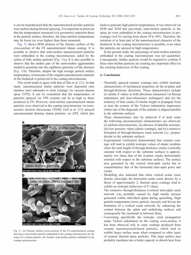
Fig. 11 shows SEM pictures of the fracture surface of thecross-section of the FS nanostructured titania coating. It ispossible to observe that semi-molten nanostructured particleswere embedded in the coating microstructure, aided by theaction of fully molten particles (Fig. 11a). It is also possible toobserve that the molten part of the semi-molten agglomeratestended to penetrate into the capillaries (porosity) of the structure(Fig. 11b). Therefore, despite the high average particle surfacetemperatures, at least part of the original nanostructural characterof the feedstock is preserved in the coating microstructure.
This result tends to agree with that of Zhu et al. [31]. In thatstudy, nanostructured titania particles were deposited ontostainless steel substrates to form coatings via vacuum plasmaspray (VPS). It can be considered that the temperatures ofparticles sprayed via VPS systems can be as high as thoseproduced in FS. However, semi-molten nanostructured titaniaparticles were observed in the coating microstructure via trans-mission electron microscopy (TEM). Gell et al. [32] sprayednanostructured alumina–titania particles via APS, which also
Fig. 11. (a) Fracture surface (cross-section) of the FS nanostructured coatingshowing a semi-molten particle embedded in the coating microstructure by theaction of a molten particle. (b) Another semi-molten particle embedded in thecoating microstructure.
tends to generate high particle temperatures. It was observed viaSEM and TEM that previously semi-molten particles in thespray jet were embedded in the coating microstructure in per-centages (vol.%) varying from about 10 to 50%. Therefore, theretention of at least part of the nanostructured character of thefeedstock in the coating microstructure is possible, even whenthe particles are sprayed at high temperatures.
In the present study, the percentage of semi-molten particlesembedded in the coating microstructure was not quantified.Consequently, further analysis would be required to confirm ifthese semi-molten particles are creating any important effect onthe cracking behaviour of this coating.
4. Conclusions
– Thermally sprayed ceramic coatings may exhibit isotropiccharacteristics of mechanical properties on the in-plane andthrough-thickness directions. These characteristics include(i) similar E values in both directions (measured via Knoopindentation and laser-ultrasonics techniques) and (ii) thetendency of four cracks of similar length to propagate fromor near the corners of the Vickers indentation impression(when one of the diagonals of the indenter is aligned parallelto the substrate surface).
– These characteristics may be achieved if at least somethe following microstructural characteristics are observed:(i) uniform microstructure, (ii) absence of lamellar structure,(iii) low porosity values (dense coatings), and (iv) extensiveformation of through-thickness crack network (i.e., perpen-dicular to the substrate surface).
– Experimental verification demonstrated that ceramic coat-ings will tend to exhibit isotropic values of elastic moduluswhen the total length of through-thickness cracks (verticallyoriented with respect to the substrate surface) is approxi-mately two times that of the in-plane cracks (horizontallyoriented with respect to the substrate surface). The surfacearea generated by the vertical intra-splat cracks has tocounterbalance that of the horizontal inter-splat pores andcracks.
– Modelling also indicated that when vertical scalar crackdensity outweighs the horizontal scalar crack density by afactor of approximately 2, thermal spray coatings tend toexhibit an isotropic behaviour of E values.
– The extensive through-thickness (vertical) intra-splat cracknetwork was probably caused by high tensile stressesgenerated within individual splats during quenching. Highparticle temperatures lower particle viscosity and favour theformation of a vertical crack network, by enhancing thecontact between the splats and underlying surfaces andconsequently the constraint in between them.
– Concerning specifically the isotropic crack propagationunder Vickers indentation on the coating cross-section, ithas been observed only in some coatings produced fromceramic nanostructured-based particles, which tend toexhibit larger surface areas when compared to other typesof ceramic thermal spray particles. This large surface areaprobably translates into a better capacity to absorb heat from

3652 R.S. Lima et al. / Surface & Coatings Technology 202 (2008) 3643–3652
the thermal spray jet, thereby lowering the viscosity of theparticle near the surface. This would result in increasedquenching rates and improved splat-to-splat adhesion.Further analysis would be required to confirm this hypoth-esis. Other factors that were not investigated in this study,such as residual stress and phase orientation (texture), mayalso play a role in this vertical microcrack formation.
– Thermal spray coatings exhibiting isotropic characteristicsof crack propagation and E values will probably responddifferently to mechanical stresses when compared to typicalcoatings. Such behaviour may lead to new types of appli-cations and improved performances.
Acknowledgements
The authors would like to thank Sulzer Metco (US) Inc.(Westbury, NY, USA), especially Mr. C. Perdikaris for thefruitful discussions and Mr. M. R. Dorfman for encouraging thisresearch.
References
[1] S. Kuroda, T.W. Clyne, Thin Solid Films 200 (1991) 49.[2] T. Nakamura, G. Qian, C.C. Berndt, J. Am. Ceram. Soc. 83 (3) (2000) 578.[3] A.J. Allen, J. Ilavsky, G.G. Long, J.S. Wallace, C.C. Berndt, H. Herman,
Acta Mater. 49 (2001) 1661.[4] J.S. Wallace, J. Ilavsky, J. Therm. Spray Technol. 7 (4) (1998) 521.[5] A. Kucuk, R.S. Lima, C.C. Berndt, J. Am. Ceram. Soc. 84 (4) (2001) 693.[6] S.-H. Leigh, C.-K. Lin, C.C. Berndt, J. Am. Ceram. Soc. 80 (8) (1997)
2093.[7] J.-F. Yang, T. Ohji, S. Kanzaki, A. Diaz, S. Hampshire, J. Am. Ceram. Soc.
85 (6) (2002) 1512.[8] M. Kachanov, I. Tsukrov, B. Shafiro, Appl. Mech. Rev. 47 (1) (January
1994) S151 (part 2).[9] F. Kroupa, M. Kachanov, in: J.V. Carstensen, T. Leffers, T. Lorentzen, O.B.
Pedersen, B.F. Sorensen, G. Winther (Eds.), Proceedings of the 19th RisøInternational Symposium on Materials Science: Modeling of Structure andMechanics of Materials from Microscale to Product, RisØ NationalLaboratory, Roskide, Denmark, 1998, p. 325.
[10] F. Kroupa, J. Dubsky, Scr. Mater. 40 (11) (1999) 1249.[11] R.S. Lima, B.R. Marple, Acta Mater. 52 (2004) 1163.[12] R.S. Lima, B.R. Marple, J. Therm. Spray Technol. 16 (1) (2007) 40.[13] C. Moreau, J.-F. Bisson, R.S. Lima, B.R. Marple, Pure Appl. Chem. 77 (2)
(2005) 443.[14] G.D. Quinn, R.C. Bradt, J. Am. Ceram. Soc., 90 (3) (2007) 673.[15] P. Ostojic, R. McPherson, Mater. Forum 10 (4) (1987) 247.[16] D.B. Marshall, T. Noma, A.G. Evans, J. Am. Ceram. Soc. 65 (10) (1982)
C–175.[17] J.-P. Monchalin, in: D.O. Thompson, D.E. Chimenti (Eds.), Review of the
Quantitative Nondestructive Evaluation, American Institute of Physics,Melville, NY, USA, 2004, p. 3.
[18] M. Levy, in: Levy, Bass, Stern (Eds.), Handbook of Elastic Properties ofSolids, Liquids and Gases, vol. II, Academic Press, 2001, p. 3.
[19] R.S. Lima, S.E. Kruger, G. Lamouche, B.R. Marple, J. Therm. SprayTechnol. 14 (1) (2005) 52.
[20] M. Miyayama, K. Koumoto, H. Yanagida, in: S.J. Schneider (Ed.),Engineered Materials Handbook – Vol. 4 – Ceramics and Glasses, ASMInternational, Materials Park, OH, USA, 1991, p. 748.
[21] N. Berger-Keller, G. Bertrand, C. Filiatre, C. Meunier, C. Coddet, Surf.Coat. Technol. 168 (2003) 281.
[22] G. Bertrand, N. Berger-Keller, C. Meunier, C. Coddet, Surf. Coat. Technol.200 (2006) 5013.
[23] R.S. Lima, B.R. Marple, Surf. Coat. Technol. 200 (2006) 3428.[24] G.R. Anstis, P. Chantikul, B.R. Lawn, D.B. Marshall, J. Am. Ceram. Soc.
64 (9) (1981) 533.[25] G. Bolelli, V. Cannillo, L. Lusvargui, T. Manfredini, Wear 261 (2006)
1298.[26] J.P. Singh, M. Sutaria, M. Ferber, Use of Indentation Technique to Measure
Elastic Modulus of Plasma-sprayed Zirconia Thermal Barrier Coating,Ceramic Engineering and Science Proceedings, vol. 18, American CeramicSociety, Westerville, OH, USA, 1997, p. 191, no. 4.
[27] G. Antou, G. Montavon, F. Hlawka, A. Cornet, C. Coddet, Mater. Charact.53 (2004) 361.
[28] A. Sharma, R.J. Gambino, S. Sampath, Acta Mater. 54 (2006) 59.[29] J. Matejicek, S. Sampath, D. Gilmore, R. Neiser, Acta Mater. 51 (2003)
873.[30] M. Prystay, P. Gougeon, C. Moreau, J. Therm. Spray Technol. 10 (1)
(2001) 67.[31] Y. Zhu, M. Huang, J. Huang, C. Ding, J. Therm. Spray Technol. 8 (2)
(1999) 219.[32] M. Gell, E.H. Jordan, Y.H. Sohn, D. Goberman, L. Shaw, T.D. Xiao, Surf.
Coat. Technol. 146–147 (2001) 48.