towards endoscopic ultrafast laser microsurgery of vocal...
TRANSCRIPT

Towards endoscopic ultrafast lasermicrosurgery of vocal folds
Christopher L. HoyW. Neil EverettMurat YildirimJames KoblerSteven M. ZeitelsAdela Ben-Yakar
Downloaded From: http://biomedicaloptics.spiedigitallibrary.org/ on 11/12/2013 Terms of Use: http://spiedl.org/terms

Towards endoscopic ultrafast laser microsurgeryof vocal folds
Christopher L. Hoy,a W. Neil Everett,a Murat Yildirim,a James Kobler,b Steven M. Zeitels,b and Adela Ben-YakaraaThe University of Texas at Austin, Department of Mechanical Engineering, Austin, Texas 78712bMassachusetts General Hospital, Center for Laryngeal Surgery and Voice Rehabilitation, Boston, Massachusetts 02114
Abstract. Vocal fold scarring is a predominant cause of voice disorders yet lacks a reliable treatment method. Theinjection of soft biomaterials to improve mechanical compliance of the vocal folds has emerged as a promisingtreatment. Here, we study the use of precise femtosecond laser microsurgery to ablate subsurface voids, with a goalof eventually creating a plane in dense subepithelial scar tissue into which biomaterials can be injected for theirimproved localization. Specifically, we demonstrate the ablation of small subepithelial voids in porcine vocal foldtissue up to 120 μm below the surface such that larger voids in the active area of vocal fold mucosa (∼3 × 10 mm2)can eventually be ablated in about 3 min. We use sub-μJ, 776-nm pulses from a compact femtosecond fiber lasersystem operating at a 500-kHz repetition rate. The use of relatively high repetition rates, with a small number ofoverlapping pulses, is critical to achieving ablation in a very short time while still avoiding significant heat deposi-tion. Additionally, we use the same laser for nonlinear optical imaging to provide visual feedback of tissue structureand to confirm successful ablation. The ablation parameters, including pulse duration, pulse energy, spot size, andscanning speed, are comparable to the specifications in our recently developed miniaturized femtosecond lasersurgery probes, illustrating the feasibility of developing an ultrafast laser surgical instrument. © 2012 Society of Photo-
Optical Instrumentation Engineers (SPIE). [DOI: 10.1117/1.JBO.17.3.038002]
Keywords: ultrafast lasers; femtosecond laser surgery; second-harmonic generation; endoscope; nonlinear optics; multiphoton process;laser-induced damage.
Paper 11709P received Nov. 30, 2011; revised manuscript received Jan. 20, 2012; accepted for publication Jan. 23, 2012; publishedonline Mar. 16, 2012.
1 IntroductionVocal fold scarring, resulting from disease, mechanical stressfrom overuse, or postsurgical healing, reduces the mechanicalcompliance of the vocal fold tissue and is a major cause ofvoice disorders. An estimated 2 to 6 million people in the UnitedStates alone suffer from chronic voice impairment due to vocalfold scarring.1 Unfortunately, no reliable treatment exists forrestoring proper phonation to scarred vocal folds. One treatmentmethod that has shown promise utilizes the injection of soft bio-materials aimed at restoring the proper viscoelasticity to thetissue.2–4 In scarred vocal fold tissue, the density of the tissueand the required injection pressure are likely to impair the properlocalization of the injected material in the desired tissue layer,thus reducing the effectiveness of the injection treatment. Toenhance the ability of surgeons to place injectables into scarredtissue with precision, we are investigating a technique that usesfemtosecond laser pulses to ablate subepithelial planar voids inthe vocal fold.
Human vocal folds have a layered structure that consists ofepithelium as the outermost layer followed by the lamina propriaand the vocalis muscle. The lamina propria is often divided ana-tomically into the superficial, intermediate, and deep laminasublayers.5 The superficial lamina propria (SLP) has a thinsheet of collagen fibers that are highly aligned along the lengthof the vocal fold in its most superficial aspect.5 Below thesefibers, the SLP consists largely of amorphous ground substance
(primarily proteoglycans and glycosaminoglycans) with scat-tered elastin and collagen fibers, fibroblasts, and other elementstypical of loose connective tissue.6 As a result, the SLP is oftendescribed as having a jelly-like viscoelasticity. The SLP inhumans is frequently referred to clinically as Reinke’s space.The SLP and the epithelial layer together make up the mucosa,which is the vibratory outer layer of the vocal fold responsiblefor phonation. Unlike adjacent respiratory mucosa, which con-tains ciliated and secretory cells, the vocal fold is covered by astratified squamous nonkeratinizing epithelium, which presum-ably is better suited to handle the contact and vibratory stressesof phonation, coughing, and other glottal functions. During thewound healing response, scar tissue can replace the superficialmucosal layer along with deeper parts of the lamina propria. Thescar tissue consists predominantly of collagen and fibronectin,both of which increase the stiffness of the mucosa and can leadto dysphonia.2
One proposed treatment method focuses on injecting softbiomaterials, such as hydrogels and microgels, to mimic themechanical properties of healthy tissue, or to inject biologicallyactive materials, such as hyaluronic acid, in an effort to limitcollagen formation.2,7,8 Surgical experience suggests that directinjection into scarred vocal fold tissue will be difficult, particu-larly when the goal is to place a layer of material in a subepithe-lial location to recreate a pliable mucosa. We hypothesize thatthe creation of a planar void in the SLP will provide a function-ally appropriate space for the injected material to fill. The planarvoid needs to cover the approximate width and length of theactive area of the mucosa affected by scarring, estimated to
Address all correspondence to: Adela Ben-Yakar, The University of Texas atAustin, Department of Mechanical Engineering, Austin, Texas 78712. Tel:+512-471-7342; Fax: 512-471-1045; E-mail: [email protected] 0091-3286/2012/$25.00 © 2012 SPIE
Journal of Biomedical Optics 17(3), 038002 (March 2012)
Journal of Biomedical Optics 038002-1 March 2012 • Vol. 17(3)
Downloaded From: http://biomedicaloptics.spiedigitallibrary.org/ on 11/12/2013 Terms of Use: http://spiedl.org/terms

be maximally 3 × 10 mm2. We hypothesize that a void willreduce the required injection pressure and improve localizationof injected materials to the superficial location occupied byhealthy SLP.
Focused ultrafast laser pulses (mode-locked laser pulses withfemtosecond or picosecond durations) are uniquely suited forcreating the subsurface void. The nonlinear absorption of tightlyfocused ultrafast laser pulses confines ablation to the focalvolume, which can be positioned inside the bulk of the tissue.Three-dimensional (3-D) confinement gives ultrafast laser abla-tion the ability to cut inside tissue without cutting through thesurface. Furthermore, the ablation process relies upon efficientabsorption and rapid buildup of a high pressure, expandingplasma/gas bubble. Since peak intensities of ultrashort laserpulses are extremely high, only small pulse energies are requiredto initiate ablation. During this highly efficient process, theenergy of ultrashort laser pulses mainly goes into the ionizationof tissue at the focal volume and for the work required to removethe ablated tissue in the form of an expanding bubble. Short dura-tion of these processes also ensures that there is minimal heatdiffusion, namely energy loss, to the surrounding tissue. There-fore, the ultrashort laser pulses reduce the energies required toinitiate ablation by orders of magnitude when compared tonanosecond or longer pulse duration laser pulses and greatlyminimize collateral damage to neighboring cells and tissues.9
Such a high degree of damage confinement is especially impor-tant when working with delicate tissue such as vocal folds and itmay help preventing scar formation. Successful laser microsur-gery of vocal fold tissue using femtosecond laser pulses has beenpreviously demonstrated, showing the potential for subsurfaceablation confined within the sublayers of the lamina propria.10
In addition to microsurgery, focused ultrafast laser pulses canbe used to generate images of biological samples through multi-photon-excited fluorescence and second harmonic generation(SHG).11 Specifically, pulses in the femtosecond regime arebest suited for nonlinear imaging of biological tissues becauseof the lower pulse energies required for signal generation.Because these techniques again rely upon the non-linear interaction of light with tissue at high intensities, signal
generation can be confined to the focal volume. This confine-ment results in an intrinsic depth-sectioning capability alongwith submicron resolution, which is sufficient to resolve the cel-lular and fibrous structures that define the various levels of thelamina propria. The use of low-energy femtosecond laser pulsesfor imaging can provide femtosecond laser microsurgerydevices a means for visualizing the region of surgery withthe identical field of view and resolution as the surgical laser.
We have recently demonstrated fiber-based miniaturizedprobes for delivering femtosecond laser pulses for microsurgery,as well as nonlinear imaging.12,13 The advent of such devicesopens the door for the development of new surgical applicationsof femtosecond laser pulses, such as the laryngeal surgical tech-nique proposed here. For the exploratory experiments presentedin this paper, we investigated the creation of thin voids withinex vivo porcine vocal fold samples using a benchtop microscopesystem. Our focus was on creating subsurface voids with laserparameters (i.e., spot size, scanning speed, and pulse energy)that are readily achievable in miniaturized, fiber-based opticalsystems and also with a single compact laser system suitablefor use in a clinical environment.
2 Methods and Materials
2.1 Experimental Setup
We used a home-built, benchtop, laser scanning microscope,combining microsurgery and nonlinear imaging capabilitiesusing a single femtosecond laser system, a 500-kHz-repeti-tion-rate erbium-doped fiber laser (Discovery, RaydianceInc.) shown in Fig. 1. When frequency-doubled, the laser pro-duces 750-fs pulses at 776 nm with a maximum pulse energy of2.5 μJ. The laser is delivered into a laser scanning microscopeand focused at the sample with a 0.75-NA, 20 × air objective(Nikon Plan Apo 20 × ∕0.75) for both nonlinear imaging andfemtosecond laser microsurgery. We deduced the focused1∕e2 spot size of the laser beam by imaging 100 nm fluorescentbeads and measuring the full width at half maximum (FWHM)of the two-photon point spread function (PSF). To better
Fig. 1 Schematic representation of the benchtop microsurgery microscope system for combined imaging and microsurgery. Femtosecond laser pulsesare delivered from a compact fiber laser system to an energy attenuator consisting of a half-wave plate (λ∕2) and polarizing cube beamsplitter (PCBS).The beam is then scanned by a pair of galvanometric scanning mirrors (SM) through a scan lens (SL) and tube lens (TL), which image the mirrors to theback aperture of a 0.75-NA 20 × objective lens (OL). The laser is then used to either ablate or image the sample on a three-axis motorized stage (XYZ).Emitted light is redirected by a cold mirror (CM) through collection optics (CO) and a laser-blocking filter (F) to the photomultiplier tube (PMT). ThePMT, stage, and scanning mirrors are all in communication with a personal computer through data acquisition cards, not shown. Inset: (a) Schematic ofthe laser scanning pattern at the sample during microsurgery. The y direction of beam scanning results from translation of the sample stage (XYZ). Forimaging, a similar raster pattern is employed; however, here the scanning mirrors provide beam scanning in both x and y directions. (b) Illustration ofthe degree of overlap between subsequent laser pulses during imaging and microsurgery.
Hoy et al.: Towards endoscopic ultrafast laser microsurgery of vocal folds
Journal of Biomedical Optics 038002-2 March 2012 • Vol. 17(3)
Downloaded From: http://biomedicaloptics.spiedigitallibrary.org/ on 11/12/2013 Terms of Use: http://spiedl.org/terms

simulate the focusing conditions in tissue, the beads were sus-pended in agar gel, and the PSF was measured between imagingdepths of 70 to 140 μm. The average lateral FWHM of the two-photon PSF was found to be 0.61 μm, which corresponds to a1.47-μm 1∕e2 diameter of the intensity distribution. The 1∕e2diameter of the intensity distribution is 2∕½lnð2Þ�1∕2 times ofthe FWHM of the two-photon PSF according to the work ofZipfel and colleagues.14 These values are comparable to thespot sizes achievable in our current miniaturized femtosecondlaser surgery probes. For microsurgery, the laser beam wasscanned by the x-axis of a pair of galvanometric scanning mir-rors (Cambridge Technologies, Inc.) sweeping the focal spot235 μm at the tissue, while the sample was translated using pre-cision stepper-motor stages (NanoMax MAX343, Thorlabs,Inc.) in the y-axis for covering 235 μm of tissue.
The duration of surgery is a key factor in development of aclinical technique. Our goal was to minimize the ablation dura-tion while using low pulse energies that are deliverable througha fiber-coupled miniature system. The duration of ablationdepends on the beam scanning speed, which in turn controlsthe degree to which sequential pulses overlap (or the distancebetween sequential pulses) at the focal plane. The degree ofpulse-to-pulse overlap, on the other hand, determines boththe ablation volume and the speed of ablation, two competingparameters that require optimization. A high degree of overlap-ping increases pulse-to-pulse accumulation effects, providingthe desired extent of tissue ablation at low pulse energies.For a fixed repetition rate, increasing pulse overlap decreasesthe speed of ablation, thus increasing the time required for ablat-ing a given region. We therefore chose to perform our experi-ments using four overlapping pulses in the x direction bydeflecting the laser beam such that 75% of the focused spot dia-meter overlapped the spot of the previous pulse. The length ofthe line scanned by the galvo-mirror on the tissue was chosento be 235 μm, which is achievable in our miniaturized femto-second laser systems.12,13 To achieve 75% pulse-to-pulse over-lap with the 235-μm scanning length, the mirror scanning speedwas 390 Hz, and the translation speed of the y-axis was0.72 mm∕s (resulting in one to two overlapping pulses in they-direction).
For multiphoton imaging, the laser beam was scanned over a430 × 430 μm2 field of view using both axes of the scanningmirrors. We separated the emitted light from the laser lightby a cold mirror (HT-1.00, CVI Laser), directed it into aPMT (H7422-40, Hamamatsu), and reconstructed the signalinto 512 × 512 pixel images at a frame rate of 0.75 framesper second. This imaging speed roughly corresponds to thesame 75% pulse-to-pulse overlap used during surgery. Wechose to keep the laser scanning speed approximately equalfor both microsurgery and imaging because most miniaturizedbeam scanning systems rely upon resonant actuation and exhibitoptimum deflection at a fixed frequency. The use of the samescanning speed for both imaging and surgery was chosen todemonstrate that both functions could be achieved in the futureby a single resonant scanning device.
During imaging, we occasionally performed simultaneoustwo-photon fluorescence (TPF) and SHG imaging with a wave-length-tunable femtosecond laser oscillator (Mai Tai, SpectraPhysics) set to 870-nm excitation wavelength and a bandpassfilter (λ0 ¼ 436 nm; Δλ ¼ 20 nm) inserted before the PMT.The filter effectively blocks the majority of TPF signal generatedat this wavelength while passing any frequency-doubled signal
generated by SHG. This protocol enables us to determinewhether the source of our signal is fluorescent or SHG in nature.We used the wavelength-tunable laser simply to access the pass-band of the filter currently used in our lab.
2.2 Ex Vivo Tissue Samples
We acquired frozen whole porcine airway specimens from alocal slaughterhouse, after which the larynx was isolated andthawed in a room-temperature saline bath. Porcine vocalfolds have a layered lamina propria similar in organizationand constituents to human vocal folds. Preliminary nonlinearimaging and histology of the superior (false) vocal fold showedthe presence of a prominent subepithelial collagen layer in theSLP, which was not identified in the inferior fold. Becausescarred human vocal fold consists of dense collagen, wechose the superior vocal fold for our experiments so as to bettermodel the structural components and sources of the nonlinearimage signal we expect to find in the first few hundred micronsof scarred human vocal fold. Additionally, recent studies suggestthat the superior vocal fold may play the dominant role in por-cine phonation, similar to the inferior or “true” vocal fold inhumans.15
After excision, the vocal fold was placed in saline and cov-ered by a glass cover slip to flatten the upper surface. The coverslip acted to gently flatten the surface of the sample so that auniform plane could be accessed for experimentation. In a clin-ical application, the glass cover slip would be akin to having thewindow of a microsurgery probe in contact with the sample, thushelping to maintain a constant depth of ablation. As a result ofthe freezing process, little cellular autofluorescence was presentfrom which the surface of the sample could be identified duringimaging. To ensure proper identification of the tissue surface,5 μL of a solution of 1-μm fluorescent beads in saline(0.002% solids after dilution in PBS, F-8823, Invitrogen) wasdeposited onto the tissue surface prior to placement of thecover slip. Samples that were to be examined by follow-uphistology were placed in 10 mL of 10% formalin (SF98-4,Fisher) immediately after ablation and TPF/SHG imaging andstored at 4°C for at least 48 h prior to delivery for histology pre-paration, paraffin embedding, sectioning, and hematoxylin andeosin (H&E) staining (TherapeUTex; Austin, Texas).
3 ResultsWe used nonlinear imaging to target the ablation within thedesired tissue architecture of the vocal folds before the ablationand to verify the success of the ablation after the procedure.Figure 2 shows a representative image stack through thevocal fold mucosa of one sample before ablation. The tissue sur-face was readily identified by the presence of the fluorescentbeads [Fig. 2(a)]. As imaging depth was increased, we detectedSHG signals that appeared to correspond to highly organizedand dense collagen fibers. The depth at which collagen fibersfirst appeared varied significantly between samples, rangingfrom 29 to 66 μm below the surface [Fig. 2(b)], while thedepth at which the image plane was entirely within the collagenvaried between 72 and 90 μm below the surface [Fig. 2(c)].
We verified whether the fibers were indeed collagen, ratherthan elastin, through use of the SHG differentiation protocoldescribed earlier. The images with and without the filter at con-stant imaging power demonstrated equal signal intensity,indicating that the signal source was SHG and not TPF; collagenfibers are well known sources of SHG, whereas nonlinear
Hoy et al.: Towards endoscopic ultrafast laser microsurgery of vocal folds
Journal of Biomedical Optics 038002-3 March 2012 • Vol. 17(3)
Downloaded From: http://biomedicaloptics.spiedigitallibrary.org/ on 11/12/2013 Terms of Use: http://spiedl.org/terms

optical signal from elastin fibers is due to the more broadbandTPF.16 The identification of a large amount of collagen highlyoriented along the length of the vocal fold is consistent withthe structure of the upper SLP in porcine vocal fold.17 We there-fore determined the collagen interface as the interface of theepithelial and SLP layers and chose it as our desired plane ofablation.
We investigated subsurface void formation by irradiating aseries of 235 × 235 μm squares at the epithelium—SLP inter-face using pulse energies of 50, 100, 500, and 750 nJ. Thesepulse energies correspond to fluences of approximately 3, 6,30 and 45 J∕cm2, respectively. The size of the ablation was cho-sen so that the entire region of interest could be visualized beforeand after ablation in the 430 × 430 μm field of view of the multi-photon microscope. In some cases, nonlinear optical imaging1 min after ablation revealed a region or regions of signalloss. We considered these dark regions as the location of thephoto-disrupted area and classified them as voids or bubbles.Because the source of the collagen imaging signal is SHG,we can rule out photobleaching as the cause of lost signalin this region. Furthermore, we observed deflection of the
surrounding collagen in cases of larger voids, supporting theview that bubble expansion occurred rather than a photochemi-cal depolymerization of collagen.
Figure 3 presents a representative example of a sampleablated with 100-nJ pulses. While we did not observe anynoticeable tissue modification using 50-nJ pulses, irradiationwith 100-nJ pulses produced a very thin plane of induced lumi-nescence around the photo-disrupted region and occasionallysmall localized voids within that region. Figure 3 shows theinduced luminescence after ablation with 100-nJ laser pulses.When a notch filter was employed to filter out broadband fluor-escent emission as before, this luminescence signal could not bedetected. The broadband nature of the luminescence signal indi-cates that it is fluorescent in nature rather than due to anenhancement or generation of second harmonic signal. Thisluminescence border appeared long-lived and could still beobserved 1 h after ablation. Though the mechanism behindthe increased luminescence has yet to be determined, this phe-nomenon has been observed by several other groups using fluor-escence imaging to visualize femtosecond laser ablation oftissue.18–20
Fig. 2 Representative nonlinear optical images of excised porcine vocal fold mucosa. (a) Three-dimensional (3-D) reconstruction of the image stack.Each image comprises a five-frame average, and the separation between each image is 2 μm. The punctuated bright spots on the surface are thefluorescent beads that were placed for surface identification. Total imaging depth is 120 μm, and lateral field of view is 430 × 430 μm2. Dottedlines in (a) represent the planes shown in (b) and (c), at depths of 46 and 72 μm below the surface, respectively. The average laser power duringimaging was 0.85 mW at the surface, gradually increasing to 4.35 mW at a depth of 120 μm below the surface. In (c), the imaging plane is entirelywithin the collagen, and the straight, strongly aligned fibers can be clearly seen.
y
x
y
-z
z
x
z
x
0 µm
-96 µm
(a) (b)
(c)
(d) (e)
(f)
y
-z
y
x
Fig. 3 Irradiation using 100 nJ pulses. (a) Second harmonic generation (SHG) images of collagen structure show the plane, 36 μm below the surface,targeted for ablation just prior to irradiation. (d) The same field of view, 1 min after irradiation with 100-nJ pulses. Cross sections through the centerlinesof (a) and (d) are provided in (b) and (c), and (e) and (f), respectively. Arrows in cross-section images indicate the imaging planes of (a) and (d). In (d), noteboth the square region of induced luminescence corresponding to the size of the ablated region and the two circular regions resulting from localizedbubble nucleation during irradiation. Two dashed circles highlight what appear to be disrupted fibers in the collagen layer, suggesting that a thinsubresolution plane may have been disrupted at this energy. Imaging depth in both sets of images is 96 μm. Scale bars are 100 μm.
Hoy et al.: Towards endoscopic ultrafast laser microsurgery of vocal folds
Journal of Biomedical Optics 038002-4 March 2012 • Vol. 17(3)
Downloaded From: http://biomedicaloptics.spiedigitallibrary.org/ on 11/12/2013 Terms of Use: http://spiedl.org/terms
At low laser fluences near the damage threshold, the extent ofablation can be smaller than the spot size of the focused laserbeam. When the imaging resolution is similar in size to the sur-gical ablation, near-threshold voids, such as those created by100-nJ pulses, would likely be difficult to identify since theywould be smaller than the imaging resolution. Accordingly,we did not observe any single large void with 100-nJ laserpulses, but instead we occasionally observed small voids inthe tissue. These voids most often occurred at the beginningor end of the ablation region and likely resulted from theseareas receiving increased exposure. Less frequently, small bub-bles were observed in the middle of the region of ablation. Thesebubbles were likely a result of inhomogeneity in the tissue thatgave rise to a slightly lower breakdown threshold at certain loca-tions. Both cases can be seen in the example shown in Fig. 3(d).The presence of induced luminescence and occasional bubblenucleation indicates that the tissue was modified when usingpulses as low as 100 nJ. However whether or not the scannedregions were entirely ablated at this energy or less will require asecondary means of verification, such as histology.
Higher pulse energies generally resulted in the formation oflarger voids within the tissue. The use of 500- and 750-nJ pulsescreated large voids that covered the scanned region of ablationand extended above and below the plane of ablation. We theo-rize that these large voids are caused by long-lasting bubblescreated at the plane of ablation that then merge and expand, dis-placing the tissue above and below the ablation plane. The
formation of bubbles that expand beyond the focal volume isconsistent with femtosecond laser ablation well above the opti-cal breakdown threshold. Increased pulse energy beyond thethreshold leads to increased maximum bubble diameter. The lar-ger amount of vaporized biomolecules produces a volume of gasthat cannot be condensed and must diffuse, leading to longerbubble lifetimes.9
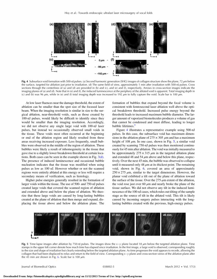
Figure 4 illustrates a representative example using 500-nJpulses. In this case, the subsurface void has maximum dimen-sions in the ablation plane of 275 × 305 μm and has a maximumheight of 108 μm. In one case, shown in Fig. 5, a similar voidcreated by scanning 750-nJ pulses was then monitored continu-ously for 45min after ablation. Thevoidwas initiallymeasured tobe approximately 275 × 315 μm in the targeted ablation planeand extended 48 and 54 μm above and below this plane, respec-tively. Over the next 45 min, the bubblewas observed to collapseuntil it measured only 48 μm at its thickest point. The remainingvoid, shown in Fig. 6, covered an area of approximately250 × 275 μm, similar to the target dimensions. However, theplanar void exhibited a tilt out of the plane of ablation towardthe surface of the tissue. Over the 275-μm extent of the ablation,the void rose just over 60 μm and nearly broke the plane of thetissue surface. We did not observe any tilt in the induced lumi-nescence of the 100-nJ cases, which rules out tilting of the samplestage as the source of tilt in the ablated void. This tilt is likelycaused by incoming surgery pulses interacting with the long-lasting bubbles created with the previous, high-energy pulses.
-192 µm
y
x
y
-z
z
x
0 µm
-96 µm
(a) (b)
(c)
(d) (e)
(f)
y
-z
y
x
z
x
Fig. 4 Subsurface void formation with 500-nJ pulses. (a) Second harmonic generation (SHG) images of collagen structure show the plane, 72 μm belowthe surface, targeted for ablation just prior to irradiation. (d) The same field of view, approximately 1 min after irradiation with 500-nJ pulses. Crosssections through the centerlines of (a) and (d) are provided in (b) and (c), and (e) and (f), respectively. Arrows in cross-section images indicate theimaging planes of (a) and (d). Note that in (e) and (f), the induced luminescence at the periphery of the ablated void is apparent. Total imaging depth in(c) and (b) was 96 μm, while in (e) and (f) total imaging depth was increased to 192 μm to fully capture the void. Scale bar is 100 μm.
Fig. 5 Time-lapse images after ablation by 750-nJ pulses. The images show the x�y plane located 18 μm below the targeted ablation plane. Timestamps in the upper left corner denote how much time has elapsed since irradiation. In the first image, a large void is observed, corresponding roughlyto the size and shape of irradiation but clearly extending below the targeted ablation plane. As time progresses the void appears to recede, allowing thecollagen that had been displaced to relax and return to the field of view. Corresponding x�y plane and cross-section views of the ablation plane afterthe 45 min are shown in Fig. 6. Scale bar is 100 μm.
Hoy et al.: Towards endoscopic ultrafast laser microsurgery of vocal folds
Journal of Biomedical Optics 038002-5 March 2012 • Vol. 17(3)
Downloaded From: http://biomedicaloptics.spiedigitallibrary.org/ on 11/12/2013 Terms of Use: http://spiedl.org/terms

Last, we ablated a series of voids using 500-nJ pulses, spaced100 μm apart, at a fixed depth of 120 μm beneath the surface toexamine by follow-up histology. The appearance of the voidsidentified in histology (Fig. 7) correlate well with the in situimages taken by nonlinear optical imaging. Figure 7(a) presentsa cross-sectional image reconstructed from nonlinear opticalimages of one void in the series, taken approximately 25 minafter ablation. From this image, the void appears to be localizedentirely within the collagen layer, with a centerline depth of116 μm and a length of 215 μm. Estimated uncertainty ofthe measurements from image size calibration is approximately�2 μm. The same void was identified during follow-up histol-ogy [Fig. 7(b)], exhibiting similar epithelial morphology, andmeasured centerline depth and length of 99 and 175 μm, respec-tively. For histological analysis, the estimated uncertainty isapproximately �1 μm. The histological measurements agreewell with the in situ measurements considering that the tissueis expected to contract during the histology preparation. Inthis histology image, no visible modification was identifiedin the cell layers above the ablated void. Another void in theseries [Fig. 7(c)] occurred underneath a thinner portion ofepithelium and even separated a small number of epithelialcells. Interestingly, the void beneath the thinner section ofepithelium is much thicker, indicating that the reduced epithelialscattering allowed more energy to reach the focal plane, subse-quently increasing void dimensions. By cutting into a small partof the epithelial layer, this void provided further evidence thatthe spaces identified in histology are in fact ablated voids (ratherthan, perhaps, an abnormally shallow blood vessel). To ensurethe epithelium is not disrupted in clinical use, future voidsshould be created at deeper depths below the tissue surface.
4 DiscussionThe imaging and void formation observed in these experimentsdemonstrate the potential for a femtosecond laser-assistedmicrosurgery/imaging technique for vocal fold restoration.By utilizing the damage confinement properties of femtosecondlaser ablation, planar voids could be created near theepithelium–SLP boundary, which may aid in the localization
of injected biomaterials. With the use of lower energy pulsesfrom the same laser system for nonlinear optical imaging ofthe sample, the structure and orientation of collagen fiberscan be clearly distinguished. In addition to determining the tis-sue type at a given depth, this ability may be useful in identify-ing scarring in the vocal fold, where scarring is expected tomanifest as dense, but less organized, collagen infiltratingthroughout the SLP. Additionally, the induced luminescencephenomenon that we observed always accompanied void forma-tion and was localized in the 3-D periphery of the ablated region.In clinical applications, it may be possible to use the inducedluminescence as a signal source to determine the extent of suc-cessful ablation. For this use, further histology of near-thresholdablations or a better understanding of the induced luminescencemechanism may be required to ensure that the presence ofinduced luminescence always indicates successful ablation. Itis possible that, just below the ablation threshold, the energyis sufficient for generation of luminescence but not ablation.
Ablation using larger pulse energies well above the opticalbreakdown threshold produced voids that expanded signifi-cantly above and below the plane of ablation. Creating largevoids may be advantageous for localizing injected materialsas they should increase the likelihood of correctly locatingthe void during injection. In the envisioned application, the bio-material is expected to track away from and along the injectionneedle during injection until it encounters the void, which willthen fill selectively as it is the path of least resistance. In the caseof the 750-nJ-irradiated void, shown in Figs. 5 and 6, weobserved that the void bubble lasted 45 min, which providesmore than ample time for injection. The interaction of surgerypulses with an expanding bubble from previous pulses appearsto have caused the ablated void to rise away from the plane ofablation toward the tissue surface. This tilt needs to be avoidedfor clinical applications, as it would prevent localization of thevoid in a consistent tissue layer over the 10 mm maximumanticipated ablation length. To reduce this source of tilting ofthe ablation plane, the pulse energy can be decreased, asshown in the 100-nJ case, or the slow-axis speed of ablationcan be increased to provide more separation between lines of
0 µm
-144 µm
y
x
y
-z
z
x
z
x
(a) (b)
(c)
(d) (e)
(f)
y
-z
y
x
Fig. 6 Subsurface void formation with 750-nJ pulses. (a) Second harmonic generation (SHG) images of collagen structure show the plane, 78 μm belowthe surface, targeted for ablation just prior to irradiation. (d) The plane targeted for ablation approximately 45 min after irradiation, once the void hadmostly collapsed. Cross sections through the centerlines of (a) and (d) are provided in (b) and (c), and (e) and (f), respectively. Arrows in cross-sectionimages indicate the imaging planes of (a) and (d). After irradiation with 750-nJ pulses, a large void was observed which then collapsed over 45 min,shown in Fig. 5. Note that in (e) and (f), the induced luminescence at the periphery of the ablated void is apparent. Also, note the tilting of the void in they�z plane in (e). During ablation, laser scanning progressed in the positive y direction. The apparent rise of the ablation during the ablation process isattributed to the interaction of incoming laser pulses with the preexisting bubble from previous pulses. Total imaging depth in both sets of images is144 μm. Scale bar is 100 μm.
Hoy et al.: Towards endoscopic ultrafast laser microsurgery of vocal folds
Journal of Biomedical Optics 038002-6 March 2012 • Vol. 17(3)
Downloaded From: http://biomedicaloptics.spiedigitallibrary.org/ on 11/12/2013 Terms of Use: http://spiedl.org/terms

ablation. The second option is most likely preferable for clinicalapplication where the clinician may wish to ensure continuousablation and a larger void.
As previously mentioned, by maintaining a constant beamscanning speed for imaging and ablation, a single resonant scan-ning device could be used to provide beam scanning within aclinical manifestation of this technique. Many miniaturizedscanning systems, such as microelectromechanical system(MEMS) mirrors and piezoelectric fiber scanners, exhibit opti-mum deflection on resonance, and the use of a single scanningdevice can greatly reduce complexity and final packaging size.The ablation dimensions are also consistent with the field ofview of our initial femtosecond-microsurgery probe prototype.12
The maximum pulse energy deliverable by our previous devicewas 350 nJ; however, the use of a reflective coating on theMEMS scanning mirror would easily increase the maximumenergy to over 900 nJ. Further improvements can be gainedby increased stretching of the pulse prior to fiber coupling toavoid damage to the fiber tip, which can greatly reduce couplingefficiency. The stretching of the pulse was the limiting conditionin our previous study for achieving higher energy deliverythrough the fiber. A longer length of air-core fiber can thenbe used to ensure proper recompression of the pulse at the sam-ple, as was demonstrated in our most recent probe prototype.13
The objective lens used in this study provided a measured spotsize of 1.47 μm inside an agar phantom at the depths we inves-tigated in our study. For comparison, point-spread function mea-surements using a 0.8-NA miniaturized aspheric lens with 3-mmdiameter in our tabletop microscope achieve a 1.1 μm 1∕e2 focalspot diameter,13 indicating that these spot sizes can be readilyachieved in miniaturized femtosecond laser systems.
With use of the scanning parameters and the 500-kHz pulserepetition rate employed in this study, a 3 × 10 mm2 area couldbe ablated in just under 3 min, which is considered acceptablefor clinical use. For comparison, the same scanning parameterscoupled with a 1-kHz rate common to most chirped-pulse ampli-fication (CPA) systems would require over 24 h to ablate thesame region, making these systems unrealistic for clinicalmicrosurgery or imaging with regard to this application.Pulse repetition rates of hundreds of kilohertz are well-suited
for this application, as these systems can easily be used forboth imaging and microsurgery above optical breakdown.Fiber laser systems such as the one used in this study are parti-cularly well-suited for clinical applications, since they are oftenmuch more compact and robust than CPA systems.
5 ConclusionWe have demonstrated the use of a single, compact, high-repetition-rate femtosecond laser system for imaging andmicrosurgery of porcine vocal fold as a first step toward thedevelopment of an ultrafast laser-assisted method of treatingscarred vocal folds in humans. Preliminary experiments showthat large long-lasting subsurface voids can be created andthat collagen fiber organization can be clearly resolved, allusing laser conditions achievable in a miniaturized fiber-based probe. Future steps will include follow-up histology ofnear-threshold ablation conditions and investigation of themaximum depth of ablation. Our goal is to now use a scarmodel to determine the degree to which the voids reduce injec-tion pressures and localize injected biomaterials.
AcknowledgmentsThis work was supported by grants from the National ScienceFoundation (IDR: CBET-1014953 and Career Award: CBET-0846868) and a grant from the Texas Ignition Fund. The authorswould like to thank Raydiance, Inc. for use of their Discoveryfiber laser, as well as Dr. R. Rox Anderson and Dr. NicholasDurr for consultation.
References1. L. O. Ramig and K. Verdolini, “Treatment efficacy: voice disorders,”
J. Speech Lang. Hear. Res. 41(1), S101–S116 (1998).2. S. Hirano, “Current treatment of vocal fold scarring,” Curr. Opin.
Otolaryngol. Head Neck Surg. 13(3), 143–147 (2005).3. S. M. Zeitels and G. B. Healy, “Laryngology and phonosurgery,” New
Engl. J. Med. 349(9), 882–892 (2003).4. S. M. Zeitels et al., “Foresight in laryngology and laryngeal surgery: a
2020 vision,” Ann. Otol. Rhinol. Laryngol. 116(Supplement 198),2–16 (2007).
Fig. 7 Histological follow-up of voids created with 500-nJ pulses. (a) Cross-sectional second harmonic generation (SHG) image of a void ablatedapproximately 120 μm beneath the tissue surface. Arrows denote the plane targeted for ablation. (b) Follow-up histology of the void shown in(a). Arrow indicates subepithelial void created by femtosecond laser ablation. (c) Histology section of a different void in the series. Arrow indicatessmall section of basal-layer cell nuclei that were separated from the epithelium during femtosecond laser ablation. Note the thicker void and the thinnerepithelium in comparison with (c). Histology images are stained by H & E. All scale bars are 50 μm.
Hoy et al.: Towards endoscopic ultrafast laser microsurgery of vocal folds
Journal of Biomedical Optics 038002-7 March 2012 • Vol. 17(3)
Downloaded From: http://biomedicaloptics.spiedigitallibrary.org/ on 11/12/2013 Terms of Use: http://spiedl.org/terms

5. J.-M. Prades et al., “Lamina propria of the human vocal fold: histomor-phometric study of collagen fibers,” Surg. Radiol. Anat. 32(4), 377–382(2010).
6. T. H. Hammond et al., “The intermediate layer: a morphologic study ofthe elastin and hyaluronic acid constituents of normal human vocalfolds,” J. Voice 11(4), 59–66 (1997).
7. M. S. Hahn et al., “Collagen composite hydrogels for vocal fold laminapropria restoration,” Biomaterials 27(7), 1104–1109 (2006).
8. X. Q. Jia et al., “Hyaluronic acid-based microgels and microgelnetworks for vocal fold regeneration,” Biomacromolecules 7(12),3336–3344 (2006).
9. A. Vogel et al., “Mechanisms of femtosecond laser nanosurgery of cellsand tissues,” Appl. Phys. B 81(8), 1015–1047 (2005).
10. H. Wisweh et al., “Optical coherence tomography monitoring ofvocal fold femtosecond laser microsurgery,” Therapeutic Laser Appli-cations and Laser-Tissue Interaction III, Proc. SPIE 6632(6),6632071–6632077 (2007).
11. W. R. Zipfel, R. M. Williams, and W. W. Webb, “Nonlinear magic:multiphoton microscopy in the biosciences,” Nat. Biotechnol. 21(11),1368–1376 (2003).
12. C. L. Hoy et al., “Miniaturized probe for femtosecond laser micro-surgery and two-photon imaging,” Opt. Express 16(13), 9996–10005(2008).
13. C. L. Hoy et al., “Optical design and imaging performance testing of a9.6-mm diameter femtosecond laser microsurgery probe,” Opt. Express19(11), 10536–10552 (2011).
14. W. R. Zipfel, R. M. Williams, and W. W. Webb, “Nonlinear magic:multiphoton microscopy in the biosciences,” Nat. Biotechnol. 21(11),1369–1377 (2003).
15. F. Alipour and S. Jaiswal, “Phonatory characteristics of excised pig,sheep, and cow larynges,” J. Acous. Soc. Am. 123(6), 4572–4581(2008).
16. A. Zoumi et al., “Imaging coronary artery microstructure using second-harmonic and two-photon fluorescence microscopy,” Biophys. J. 87(4),2778–2786 (2004).
17. C. Boudoux et al., “Preliminary evaluation of noninvasive microscopicimaging techniques for the study of vocal fold development,” J. Voice23(3), 269–276 (2009).
18. K. König, O. Krauss, and I. Riemann, “Intratissue surgery with 80 MHznanojoule femtosecond laser pulses in the near infrared,” Opt. Express10(3), 171–176 (2002).
19. J. A. Galbraith and M. Terasaki, “Controlled damage in thick specimensby multiphoton excitation,” Mol. Biol. Cell 14(5), 1808–1817 (2003).
20. B. G. Wang et al., “Multiphoton microscopy for monitoring intratissuefemtosecond laser surgery effects,” Lasers Surg. Med. 39(6), 527–533(2007).
Hoy et al.: Towards endoscopic ultrafast laser microsurgery of vocal folds
Journal of Biomedical Optics 038002-8 March 2012 • Vol. 17(3)
Downloaded From: http://biomedicaloptics.spiedigitallibrary.org/ on 11/12/2013 Terms of Use: http://spiedl.org/terms