towards a synchronization theory of microwave-induced zero
TRANSCRIPT

See discussions, stats, and author profiles for this publication at: https://www.researchgate.net/publication/235438798
Towards a synchronization theory of microwave-induced zero-resistance
states
Article in Physical Review B · July 2013
DOI: 10.1103/PhysRevB.88.035410 · Source: arXiv
CITATIONS
49READS
78
3 authors, including:
Some of the authors of this publication are also working on these related projects:
Quantum-Classical Correspondence View project
ELASTIC ENHANCEMENT FACTOR View project
O. Zhirov
Budker Institute of Nuclear Physics
66 PUBLICATIONS 793 CITATIONS
SEE PROFILE
All content following this page was uploaded by O. Zhirov on 30 May 2014.
The user has requested enhancement of the downloaded file.

PHYSICAL REVIEW B 88, 035410 (2013)
Towards a synchronization theory of microwave-induced zero-resistance states
O. V. Zhirov,1 A. D. Chepelianskii,2 and D. L. Shepelyansky3
1Budker Institute of Nuclear Physics, 630090 Novosibirsk, Russia2Cavendish Laboratory, Department of Physics, University of Cambridge, CB3 0HE, United Kingdom
3Laboratoire de Physique Theorique du CNRS, IRSAMC, Universite de Toulouse, UPS, 31062 Toulouse, France(Received 12 February 2013; revised manuscript received 27 April 2013; published 3 July 2013)
We develop a synchronization theory for the dynamics of two-dimensional electrons under a perpendicularmagnetic field and microwave irradiation showing that dissipative effects can lead to the synchronization of thecyclotron phase with the driving microwave phase at certain resonant ratios between microwave and cyclotronfrequencies. We demonstrate two important consequences of this effect: the stabilization of skipping orbits alongthe sample edges and the trapping of the electrons on localized short-ranged impurities. We then discuss howthese effects influence the transport properties of ultrahigh-mobility two-dimensional electron gas and proposemechanisms by which they lead to microwave-induced zero-resistance states. Our theoretical analysis showsthat the classical electron dynamics along the edge and around circular disk impurities is well described by theChirikov standard map providing a unified formalism for those two rather different cases. We argue that thiswork will provide the foundations for a full quantum synchronization theory of zero-resistance states for whicha fully microscopic detailed theory still should be developed.
DOI: 10.1103/PhysRevB.88.035410 PACS number(s): 73.40.−c, 05.45.−a, 72.20.My
I. INTRODUCTION
The experiments on resistivity of high-mobility two-dimensional electron gas (2DEG) in the presence of arelatively weak magnetic field and microwave radiation ledto a discovery of striking zero-resistance states (ZRS) inducedby a microwave field by Mani et al.1 and Zudov et al.2 Otherexperimental groups also found the microwave-induced ZRSin various 2DEG samples (see, e.g., Refs. 3–5). A similarbehavior of resistivity is also observed for electrons on asurface of liquid helium in the presence of magnetic andmicrowave fields.6,7 These experimental results obtained withdifferent systems stress the generic nature of ZRS. Varioustheoretical explications for this striking phenomenon havebeen proposed during the decade after the first experiments.1,2
An overview of experimental and theoretical results is give ina recent review.8
In our opinion the most intriguing feature of ZRS is theiralmost periodic structure as a function of the ratio j = ω/ωc
between the microwave frequency ω and cyclotron frequencyωc = eB/mc (in the following we are using units with electroncharge e and mass m equal to unity). Indeed, the Hamiltonian ofelectrons in a magnetic field is equivalent to an oscillator; it hasa magnetoplasmon resonance at j = 1 but in a linear oscillatorthere are no matrix elements at j = 2,3, . . . and hence arelatively weak microwave field is not expected to affectelectron dynamics and resistivity properties of transport. Ofcourse, one can argue that impurities can generate harmonicsbeing resonant at high j > 1 but ZRS is observed only inhigh-mobility samples and thus the density of impurities isexpected to be rather low. It is also important to note that ZRSappears at high Landau levels ν ∼ 50 so that a semiclassicalanalysis of the phenomenon seems to be rather relevant.
In this work we develop the theoretical approach proposedin Ref. 9. This approach argues that impurities produce onlysmooth potential variations inside a bulk of a sample sothat ZRS at high j appear from the orbits moving alongsharp sample boundaries. It is shown9 that collisions with
boundaries naturally generate high harmonics and that amoderate microwave field gives stabilization of edge channeltransport of electrons in a vicinity of j ≈ jr = 1 + 1/4, 2 +1/4, 3 + 1/4, . . . producing at these j a resistance goingto zero with increasing microwave power. This theory isbased on classical dynamics of electrons along a sharpedge. The treatment of relaxation processes is modeled ina phenomenological way by a dissipative term in the Newtonequations. An additional noise term in the dynamical equationstakes into account thermal fluctuations. The dissipation leadsto synchronization of the cyclotron phase with a phase ofmicrowave field producing stabilization of edge transportalong the edges in the vicinity of resonant jr values. Thus,according to the edge stabilization theory9 the ZRS phase isrelated to a universal synchronization phenomenon which is awell-established concept in nonlinear sciences.10
While the description of edge transport stabilization9
captures a number of important features observed in ZRSexperiments it assumes that the contribution of bulk orbitsin transport is negligibly small. This assumption is justifiedfor smooth potential variations inside the bulk of a sample.However, the presence of isolated small-scale scatterers insidethe bulk combined with a smooth potential component cansignificantly affect the transport properties of electrons (see,e.g., Ref. 11). Also the majority of theoretical explanationsof the ZRS phenomenon considers only a contribution ofscattering in a bulk.8 Thus it is necessary to analyze how ascattering on a single impurity is affected by a combined actionof magnetic and microwave fields. In this work we performsuch an analysis modeling impurity by a rigid circular diskof finite radius. We show that the dynamics in the vicinity ofa disk has significant similarities with the dynamics of orbitsalong a sharp edge leading to the appearance of ZRS-typefeatures in a resistivity dependence on j .
The paper is composed as follows: In Sec. II we discuss thedynamics in the edge vicinity; in Sec. III we analyze scatteringon a single disk; in Sec. IV we study scattering on many disks
035410-11098-0121/2013/88(3)/035410(14) ©2013 American Physical Society

ZHIROV, CHEPELIANSKII, AND SHEPELYANSKY PHYSICAL REVIEW B 88, 035410 (2013)
when their density is low—here we determine the resistivitydependence on j and other system parameters. Physical scalesof ZRS effects are analyzed in Sec. V; the effects of twomicrowave driving fields and other theory predictions areconsidered in Sec. VI; and discussion of the results is given inSec. VII.
We study various models which we list here for thereader’s convenience: the wall model described by the Newtonequations (1) and (2) with microwave field polarizationperpendicular to the wall [model (W1) equivalent to model(1) in Ref. 9]; the Chirikov standard map description (3) ofthe wall model dynamics called model (W2) [equivalent tomodel (2) in Ref. 9 at parameter ρ = 1]; the single-disk modelwith radial microwave field called model (DR1); the Chirikovstandard map description (3) of model (DR1) called model(DR2) [here vy → vr in (3), ρ > 1]; the model of a single diskin a linearly polarized microwave field and static electric fieldcalled model (D1); the model of transport in a system withmany disks called model (D2) which extends model (D1); anextension of model (D2) with disk roughness and dissipationin space called model (D3); the wall model (W2) extended totwo microwave fields is called model (W3).
II. DYNAMICS IN EDGE VICINITY
We recall first the approach developed in Ref. 9. Here,the classical electron dynamics is considered in the proximityof the Fermi surface and in the vicinity of the sample edgemodeled as a specular wall. The motion is described by Newtonequations
dv/dt = ωc × v + ω�ε cos ωt − γ (v)v + Iec + Is, (1)
where a dimensionless vector �ε = eE/(mωvF ) describesmicrowave driving field E. Here an electron velocity v ismeasured in units of Fermi velocity vF and γ (v) = γ0(|v|2 −1) describes a relaxation processes to the Fermi surface. Wealso use the dimensionless amplitude of velocity oscillationsinduced by a microwave field ε = e|E|/(mωvF ). As in Ref. 9,in the following we use units with vF = 1. The last two termsIec and Is in (1) account for elastic collisions with the walland small-angle scattering. Disorder scattering is modeled asrandom rotations of v by small angles in the interval ±αi
with Poissonian distribution over time interval τi = 1/ω. Theamplitude of noise is assumed to be relatively small so thatthe mean-free path e is much larger than the cyclotron radiusrc = vF /ωc. We note that the dissipative term is also known asa Gaussian thermostat12 or as a Landau-Stuart dissipation.10
The dynamical evolution described by Eq. (1) is simulatednumerically using the Runge-Kutta method. Following Ref. 9we call this system model (W1) [equivalent to model (1) inRef. 9].
We note that for typical experimental ZRS parame-ters we have electron density ne = 3.5 × 1011 cm−2, ef-fective electron mass m = 0.065me, microwave frequencyf = ω/2π = 50 GHz, and Fermi energy EF = mv2
F /2 =πneh
2/m = 0.01289 V, corresponding to EF /kB = 149.5 K,with Fermi velocity vF = 2.641 × 107 cm/s. At such afrequency the cyclotron resonance ω = ωc = eB/mc takesplace at B = 0.1161 T with the cyclotron radius rc = vF /ωc =0.8873 μm. At such a magnetic field we have the energy
spacing between Landau levels hω = hωc = 0.2067 mV =2.40 K × kB corresponding to a Landau level ν = EF /hωc ≈62. For a microwave field strength E = 1 V/cm we have theparameter ε = eE/(mωvF ) = 0.003261. With these physicalvalues of system parameters we can always recover thephysical quantities from our dimensionless units with m =e = vF = 1.
Examples of orbits running along the edge of specular wallare given in Ref. 9 (see Fig. 1 there). A microwave fieldcreates resonances between the microwave frequency ω and afrequency of nonlinear oscillations of orbits colliding with thewall. Due to the specular nature of this collision the electronmotion has high harmonics of cyclotron frequency that leadsto the appearance of resonances around j = 1,2,3,4, . . . (thereis an additional shift of approximate value 1/4 to jr values dueto a finite width of nonlinear resonance).
To characterize the dynamical motion it is useful toconstruct the Poincare section following the standard methodsof nonlinear systems.13,14 We consider the Hamiltonian caseat γ0 = 0 in the absence of noise. Also we choose a linearpolarized microwave field being perpendicular to the wallwhich is going along the x axis (same geometry as in Ref. 9).In this case the generalized momentum px = vx + By = yc isan integral of motion since there are no potential forces acting
0.0
0.5
1.0
1.5
2.0
2.5
0.0
0.2
0.4
0.6
0.8
0.0
0.2
0.4
0.6
0.8
-1.0 -0.5 0.0 0.5 1.0-1.0 -0.5 0.0 0.5 1.0
v r/v
0v r
/v0
v r/v
0
φ/π φ/π
FIG. 1. Poincare sections of Hamiltonian (2) for j = 7/4 (leftcolumn) and j = 9/4 (right column) and different amplitudes ofmicrowave field ε = 0.02,0.04,0.2 (from bottom to top). Here, theintegral px/mvF = 1, trajectories start from wall with fixed vx =px = v0 = 1. Data for model (W1) at γ0 = 0, αi = 0.
035410-2
TOWARDS A SYNCHRONIZATION THEORY OF . . . PHYSICAL REVIEW B 88, 035410 (2013)
on electrons along the wall (here we use the Landau gauge witha vector potential Ax = By). The momentum px determinesa distance yc between a cyclotron center and the wall, whichalso remains constant in time. The Hamiltonian of the systemhas the form
H = p2y/2 + (px − By)2/2 + εωy cos ωt + Vw(y), (2)
where Vw(y) is the wall potential being zero or infinity fory < 0 or y � 0. Thus, we have here a so-called case of one anda half degrees of freedom (due to periodic dependence of theHamiltonian on time) and the Poincare section has continuousinvariant curves in the integrable regions of phase space.13,14
The Poincare sections for (1) and (2) at j = 7/4,9/4 andvarious amplitudes of microwave field ε are shown in Fig. 1.It shows a velocity vy at moments of collision with the wallat y = 0 as a function of microwave phase φ = ωt at thesemoments of time. All orbits initially start at the wall edgey = 0 with the initial velocity vx = v0 = px = yc. The valueof px = yc is the integral of motion. However, the kineticenergy of electron Ek = (v2
x + v2y)/2 varies with time. We see
that at a small ε = 0.02 the main part of the phase spaceis covered by invariant curves corresponding to integrabledynamics. However, the presence of a chaotic component withscattered points is also visible in the vicinity of the separatrix ofresonances, especially at large ε = 0.2. The points at vy closeto zero correspond to orbits only slightly touching the wall,while the orbits at vy/v0 � 1 have a large cyclotron radius andcollide with the wall almost perpendicularly. There are alsosliding orbits which have the center of cyclotron orbit insidethe wall (yc > 0) but we do not discuss them here. Indeed,the orbits, which only slightly touch the wall (yc ≈ −vF /ωc),play the most important role for transport since the scatteringangles in the bulk are small for high-mobility samples andan exchange between bulk and edge goes via such type ofdominant orbits.9
We note that the section of Fig. 1 at j = 9/4, ε = 0.02 isin a good agreement with those shown in Fig. 1(b) of Ref. 9.However, here we have single invariant curves while in Ref. 9the curves have a certain finite width. This happens due tothe fact that in Ref. 9 the Poincare section was done withtrajectories having different values of the integral px = yc thatgave some broadening of invariant curves. For a fixed integralvalue we have no overlap between invariant curves as is wellseen in Fig. 1 here.
The phase space in Fig. 1 has a characteristic resonanceat a certain vy/v0 value which position depends on j .9 Anapproximate description of the electron dynamics and phasespace structure can be obtained on a basis of the Chirikovstandard map.13–15 In this description developed in Ref. 9 anelectron velocity has an oscillating component δvy = ε sin ωt
(assuming that ω > ωc) and a collision with the wall gives achange of modulus of vy by 2δvy (like a collision with a movingwall). For small collision angles the time between collisionsis t = 2(π − vy)/ωc. Indeed, 2π/ωc is the cyclotron period.However, the time between collisions is slightly smaller byan amount 2vy/ωc: At vy � vx ≈ vF an electron moves inan effective triangular well created by the Lorentz force andlike for a stone thrown against a gravitational field this givesthe above reduction of t (formally this expression for t isvalid for sliding orbits but for orbits slightly touching the wall
we have the same t but with minus that gives the correction−2vy/ωc). The same result can be obtained via semiclassicalquantization of edge states developed in Ref. 16. It also can befound from a geometric overlap between the wall and cyclotroncircle. This yields an approximate dynamics description interms of the Chirikov standard map:13
vy = vy + 2ε sin φ + Icc, φ = φ + 2(π − vy/ρ)ω/ωc, (3)
with the chaos parameter K = 4εω/(ρωc). Usually we are inthe integrable regime with K < 1 due to small values of ε usedin experiments. A developed chaos appears at K > 1.13,14 Herebars mark the new values of variables going from one collisionto a next one, vy is the velocity component perpendicular tothe wall, and φ = ωt is the microwave phase at the momentof collision. Here we introduced a dimensionless parameter ρ
which is equal to ρ = 1 for the case of the wall model (W2)considered here. However, we will show that for the dynamicsaround a disk with a radial field in model (DR1) we havethe same map (3) with ρ = 1 + rc/rd . Thus it is convenientto write all formulas with ρ. We note that a similar map(3) describes also a particle dynamics in a one-dimensionaltriangular well and a monochromatic field.17
The term Icc = −γcvy + αn in (3) describes dissipationand noise. The latter gives fluctuations of velocity vy at eachiteration [−α < αn < α; corresponding to random rotation ofvelocity vector in (1)]. Damping from electron-phonon andelectron-electron collisions contributes to γc. The Poincaresections of this map are in good agreement with those obtainedfrom the Hamiltonian dynamics as seen in Fig. 1 here and inFig. 1 in Ref. 9. Following Ref. 9 we call this system model(W2) [equivalent to model (2) in Ref. 9].
A phase shift of φ by 2π does not affect the dynamicsand thus the phase space structure changes periodically withinteger values of j . Indeed, the position of the main resonancecorresponds to a change of phase by an integer numberof 2π values φ − φ = 2πm = 2(π − vy/ρ)ω/ωc that givesthe position of resonance at vres = vy = πρ(1 − mωc/ω) =πρδj/j where m is the nearest integer of ω/ωc and δj is thefractional part of j . Due to this relation we have the differentresonance position for j = 7/4 and 9/4 being in agreementwith the data of Fig. 1 at small values of ε when nonlinearcorrections are small (we have here ρ = 1). Thus at j = 9/4we have the resonance position at vy = 0.1111π ≈ 0.35 inagreement with Fig. 1 (right bottom panel). For j = 2 wehave vy = 0 and at j = 7/4 the resonance position moves to anegative value vy = −0.45. Thus, at j = 2; 7/4 the resonanceseparatrix easily moves particles out from the edge at vy < 0where they escape to the bulk due to noise. In contrast atj = 9/4 particles move along the separatrix closer to theedge being then captured inside the resonance which givessynchronization of the cyclotron phase with the microwavephase. This mechanism stabilizes the transmission along theedge.
In Ref. 9 it is shown that the orbits started in the edgevicinity are strongly affected by a microwave field that leadsto ZRS-type oscillations of transmission along the edge andlongitudinal resistivity Rxx . The ZRS structure appears both inthe frame of dynamics described by (1) [model (W1)] and inmap description (3) [model (W2)]. The physical mechanismis based on synchronization of a cyclotron phase with a phase
035410-3

ZHIROV, CHEPELIANSKII, AND SHEPELYANSKY PHYSICAL REVIEW B 88, 035410 (2013)
-4
-2
0
2
4
1 2 3 4 5 6 7 1 2 3 4 5 6 7
yc/r c
j j
FIG. 2. (Color online) Density distribution w of electrons asa function of their dimensionless cyclotron center position yc/rc
between two walls and the frequency ratio j = ω/ωc. The distancebetween specular walls is 6rc. The amplitude of microwave field isε = 0.1 with polarization parallel (left panel) and perpendicular (rightpanel) to the walls (see text for more details). Here γ0/ω = 0.05,αi = 0.01, τi = 1/ω. The variation of j = ω/ωc is obtained bychanging magnetic field (ωc = B) keeping ω = const.; 100 electronsare simulated at each j up to time tr = 105/ω. Density is proportionalto color changing from zero (black) to maximal density (white). Datafor model (W1).
of microwave driving that leads to stabilization of electrontransport along the edge. An extensive amount of numericaldata has been presented in Ref. 9 and we think there is noneed to add more. Here, we simply want to illustrate thateven those orbits which start in the bulk are affected bythis synchronization effect. For that we take a band of twowalls with a bandwidth between them being y = L = 6rc.Initially 100 trajectories are distributed randomly in a bulkpart between walls when a cyclotron radius is not touching thewalls (−2rc < yc < 2rc). Their dynamics is followed duringthe run time tr = 105/ω according to Eq. (1) and a densitydistribution w(yc) averaged in a time interval 5 × 10⁴ < ωt <
105 is obtained for a range of 0.5 � j � 7 (261 values ofj are taken homogeneously in this interval). The value of trapproximately corresponds to a distance propagation alongthe wall of rw ∼ vytr ∼ 0.1vF tr ∼ 5 × 10³vF /ω ∼ 0.2 cm attypical values vF ∼ 2 × 107 cm/s, ω/2π = 100 GHz. This iscomparable with a usual sample size used in experiments.1,2
Similar values of rw were used in Ref. 9.The dependence of density w on yc and j is shown in Fig. 2
for two polarizations of the microwave field. The data showthat orbits from a bulk can be captured in the edge vicinityfor a long time giving an increase of density in the vicinityof the edge. This capture is significant around resonancevalues j ≈ jr . This is confirmed by a direct comparison ofdensity profiles in Fig. 3 at j = 1.7 ≈ 2 − 1/4 and j = 2.4 ≈2 + 1/4. In the latter case we have a large density peak due totrajectories trapped in a resonance (see Fig. 1) where they aresynchronized with the microwave field. An increase of noiseamplitude αi gives a significant reduction of the amplitude ofthese resonant peaks (Fig. 3, bottom panels). The increaseof density is more pronounced for polarization perpendic-ular to the wall in agreement with data shown in Fig. 2of Ref. 9.
The results of Figs. 2 and 3 clearly show that the electronsfrom the bulk can be trapped by a microwave field in an edgevicinity that enhances the propagation along the edge. At thesame time the skipping orbits, the cyclotron circle center of
0.0
0.3
0.6
0.0
0.3
0.6
0
1
2
-3 -2 -1 0 1 2 3
0.0
0.3
0.6
0.0
0.3
0.6
0
1
2
-3 -2 -1 0 1 2 3
w
yc/rc yc/rc
FIG. 3. Profile of density distribution w(yc) as a function of yc/rc
for microwave polarization parallel (left panels) and perpendicular(right panels) to the walls. Here we have no microwave at top panels,ε = 0.1, j = 1.7 at middle panels, ε = 0.1, j = 2.4 at bottom panels.In all panels we have noise amplitude αi = 0.01 as in Fig. 2; dashedcurves in bottom panels are obtained with αi = 0.05. Simulations aredone with 500 trajectories, other parameters are the same as in Fig. 2.Data for model (W1).
which is outside the sample, are practically unaffected by amicrowave field (indeed, from Fig. 3 we see a significantdensity drop at the edge vicinity that results from a separationof skipping orbits from those linked with the bulk). Such orbitsremain disconnected from the bulk and hence they do not givesignificant contribution to Rxx as is the case in absence ofmicrowave field.
We also performed numerical simulations using Eq. (1)with a smooth wall modeled by a potential Vw(y) = κy2/2.For large values κ/ωc (e.g., κ/ωc = 10) we find the Poincaresections to be rather similar to those shown in Fig. 1 that givesa similar structure of electron density as in Figs. 2 and 3. Afinite wall rigidity can produce a certain shift of optimal captureconditions appearing as a result of additional correction to acyclotron period due to a part of orbit inside the wall.
The data presented in this section show that electrons fromthe bulk part of the sample can be captured for a long timein the edge vicinity thereby increasing the electron densitynear the edge. This effect is very similar to the accumulationof electrons on the edges of the electron cloud under ZRSconditions that was reported for surface electrons on heliumin Ref. 7. However we have to emphasize that the confinementpotential for surface electrons is very different from the hardwall potential assumed in our simulations; as a consequenceour results cannot be applied directly to this case. It is possiblethat the formation of ballistic channels on the edge of thesample combined with the redistribution of the electron densitycan effectively short the bulk contribution and induce directly avanishing Rxx . However, it is also very important to understandhow a scattering on impurities inside the bulk is affectedby a microwave radiation. Indeed, the volume of the bulkis significantly larger than the volume of strips of cyclotronradius width along the edges. Thus a presence of low-densitysharp impurity scatterers inside the bulk can give the dominantcontribution to the global resistivity of a large-size sample.
035410-4

TOWARDS A SYNCHRONIZATION THEORY OF . . . PHYSICAL REVIEW B 88, 035410 (2013)
Hence, the analysis of scattering inside the bulk is veryimportant. We study this question in the next sections.
III. SCATTERING ON A SINGLE DISK
It should be noted that resistivity properties of a reg-ular lattice of disk antidots in 2DEG have been studiedexperimentally18,19 and theoretically.20,21 But the effects ofthe microwave field were not considered till present.
In our studies we model an impurity as a rigid disk of fixedradius rd ; we measure rd in units of distance vF /ω, keepingω = constant and changing ωc = B. We usually have a fixedratio rdω/vF = 1. In a magnetic field a cyclotron radius movesin free space only due to a static dc electric field Edc. We fixthe direction of Edc along the x axis and measure its strengthby a dimensionless parameter εs = Edc/(ωvF ). Even in theabsence of a microwave field a motion in the vicinity of thedisk in crossed static electric and magnetic fields of moderatestrength is not so simple. The studies presented in Refs. 22and 23 show that dynamics in the disk vicinity is described by asymplectic disk map which is rather similar to the map (3). It ischaracterized by a chaos parameter εd = 2πvd/(rdωc) wherevd = Edc/B is the drift velocity; εd gives an amplitude ofchange of radial velocity at collision. Orbits from the vicinityof the disk can escape for εd > 0.45.22
We start our analysis from the construction of the Poincaresection in the presence of the microwave field at zero staticfield. To have a case with one and half degrees of freedom westart from a model case when the microwave field is directedonly along the radius from the disk center. The dynamicsis described by Eq. (1) with a dimensionless microwaveamplitude ε. The dynamical evolution is obtained numericallyby the Runge-Kutta method. At first we consider a case withoutdissipation and noise. Due to radial force direction the orbitalmomentum is an additional integral of motion (as px = yc forthe wall case) and thus we have again 3/2 degrees of freedom.We call this disk model with radial microwave field as model(DR1).
The Poincare sections at the moments of collisions with thedisk are shown in Figs. 4 and 5 for model (DR1). Here, vr is theradial component of electron velocity and φ is a microwavephase both taken at the moment of collision with the disk.We see that the phase space structure remains approximatelythe same when j is increased by unity (compare j = 9/4,13/4panels in Fig. 4). This happens for orbits only slightly touchingthe disk (small vr ) since the microwave phase change duringa cyclotron period is shifted by an integer amount of 2π (ina first approximation at rd � rc). The similarity between thewall and disk cases is directly seen from Fig. 5 as well asperiodicity with j → j + 1.
In fact in the case of a disk with a radial field the dynamicscan be also described by the Chirikov standard map (3) wherevy should be understood as a radial velocity vr at the momentof collision. The second equation has the same form since thechange of the phase between two collisions is given by the sameequation but with the parameter ρ = 1 + rc/rd . This expres-sion for ρ is obtained from the geometry of slightly intersectingcircles of radius rd for disk and radius rc for cyclotron orbit(the angle segment of the cyclotron circle is ϕ = 2vr/ρ).For rd � rc this expression naturally reproduces the wall case
0.0
0.2
0.4
0.6
0.8
1.0
0.0
0.2
0.4
0.6
0.8
1.0
0.0
0.2
0.4
0.6
0.8
1.0
-1.0 -0.5 0.0 0.5 1.0-1.0 -0.5 0.0 0.5 1.0
v r/v
0v r
/v0
v r/v
0
φ/π φ/π
FIG. 4. Poincare section for Hamiltonian dynamics in a diskvicinity in presence of radial microwave field. Left column panels:j = 7/4,2,9/4 at ε = 0.04 (from top to bottom); right columnpanels: j = 7/4,13/4,9/4 at ε = 0.02. Here the integral of orbitalmomentum is 0/vF rd = v0/vF = 1, trajectories start from disk withfixed tangent velocity component v0 = 1. Data for model (DR1).
0.00.20.40.60.8
0.00.20.40.6
0.00.20.40.6
-1.0 -0.5 0.0 0.5 1.0
0.00.40.81.21.6
0.00.40.81.2
0.00.40.81.2
-1.0 -0.5 0.0 0.5 1.0
v yv y
v y
v yv y
v y
φ/π φ/π
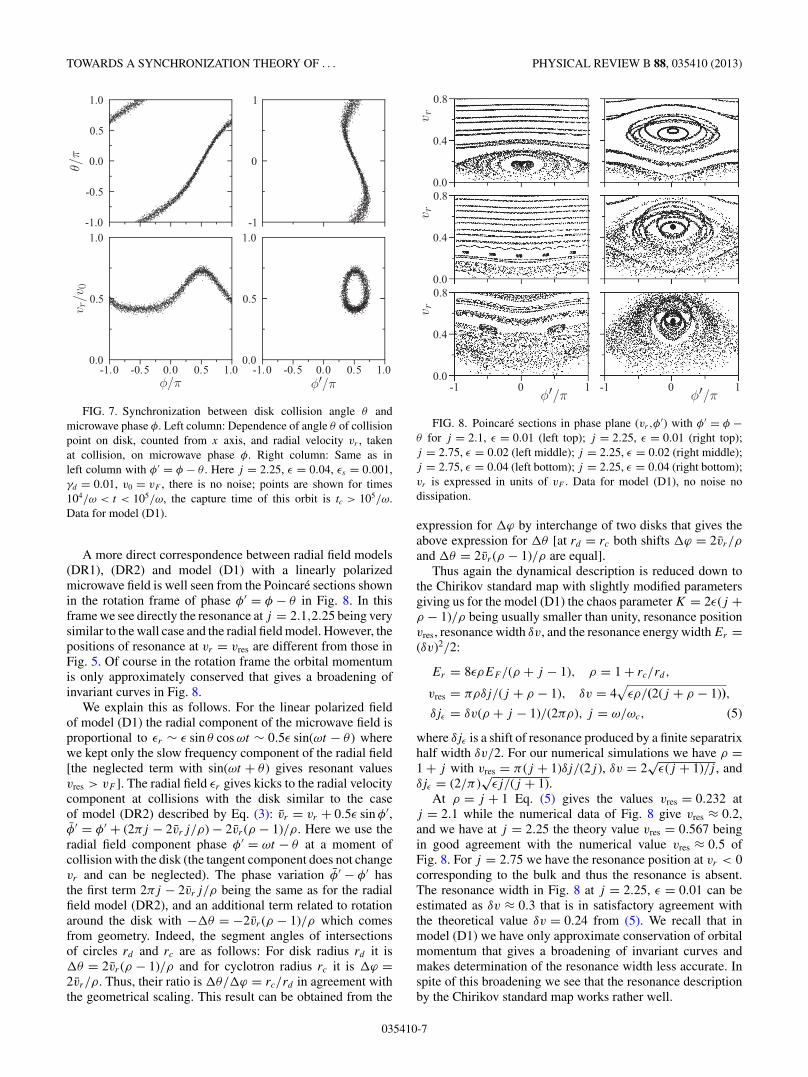
FIG. 5. Poincare sections for wall model (W1) (left) and diskmodel with radial electric field (DR1) (right) at ε = 0.01 and j = 2.1(top, middle) and j = 3.1 (bottom). Top panels are obtained from theChirikov standard map (3) at ρ = 1 (left top panel), correspondingto the wall model (W2), and at ρ = 1 + j = 3.1 (right top panel),corresponding to the disk model (DR2). Middle and bottom panelsare obtained from solution of Newton equations (1) for wall (left) anddisk (right). Other parameters are as in Fig. 1 and Fig. 4; vy and vr
are expressed in units of vF . There is no dissipation and no noise.
035410-5
ZHIROV, CHEPELIANSKII, AND SHEPELYANSKY PHYSICAL REVIEW B 88, 035410 (2013)
while at rd � rc we have the correction term proportional to vy
going to zero that also well corresponds to the geometry of twodisks. After such modification of ρ we find that the resonancepositions vres = πρδj/j are proportional to ρ. Thus the model(DR1) reduced to the map description (3) at ρ > 1 is calledmodel (DR2).
The expression for vres works rather well. Indeed, for j =2.1 in Fig. 5 we obtain vres = 0.149 for model (W2) and 0.463for model (DR2). These values are in a good agreement withnumerical values vres ≈ 0.15 for model (W2) and vres ≈ 0.6 formodel (DR1). In the latter case the agreement is less accuratedue to a larger size of nonlinear resonance. The comparisonof Poincare sections given by the Chirikov standard map (3)and the dynamics from Newton equations, shown in Fig. 5,confirm the validity of the map description.
According to the well-established results for the Chirikovstandard map13 we find for models (W1), (W2) and (DR1),(DR2) the width of separatrix δv and the correspondingresonance energy width Er = (δv)2/2:
Er = 16εωcρEF /ω, ρ = 1 + rc/rd,
vres = πρδj/j, δv = 4√
ερ/j, (4)
δjε = δvj/(2πρ), j = ω/ωc,
where δjε is the resonance shift produced by a resonance halfwidth δv/2 = vres. This relation shows that for the disk casethis energy is increased by a factor ρ compared to the wallcase. In the majority of our numerical simulations we haveρ = 1 + j .
Thus the radial field models (DR1), (DR2) represent auseful approximation to understand the properties of dynamicsin the disk vicinity, but a real situation corresponds to a linearmicrowave polarization and the Poincare section analysisshould be modified to understand the dynamics in this case.
Therefore we start to analyze the scattering problem on adisk in the presence of weak static field εs and microwave fieldε using Eq. (1). For the scattering problem we find it moresimple to have dissipation work only at the time momentsof electron collisions with disk: At such time moments themodulus of electron velocity is reduced by a factor |v| →|v|/(1 + γd ); the reduction is done only if the kinetic energy ofthe electrons is larger than the Fermi energy. Such a dissipationcan be induced by phonon excitations inside the antidot disk.We fix the geometry directing the dc field along the x axis andmicrowaves along the y axis. The noise is modeled in the sameway as above in Eq. (1). We call this system disk model (D1).Below we present data for a fixed value of γd = 0.01 but wechecked that the variation of this parameter by a factor 2–3 doesnot modify the typical dependence Rxx(j ) presented below.
We note that the presence of dissipation only in the vicinityof the disk corresponds to the experimental reality: The ZRSeffect exists only in high-mobility samples; in a free spacewithout disks we have only a small smooth angle scatteringwhich cannot generate j > 1 resonances due to the absenceof such matrix elements in an oscillator potential effectivelycreated by a magnetic field. Therefore the dissipative processesgive significant contribution to transport only in the vicinity ofsharp impurities (disks) or sample edges.
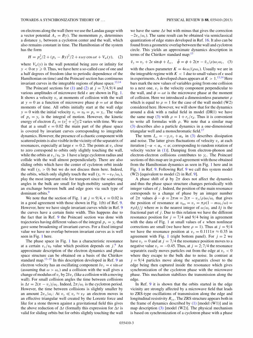
Examples of electron cyclotron trajectories scattering on adisk are shown in Fig. 6. In the absence of the microwave field
-6
-4
-2
0
2
4
6
...................................................................
...................................................................
...................................................................
............................................................. .. ......
...
......................................................................
...................................................................
..................................................................
................................................
.............................................................................................................................................................................................................................................................................................................................................................................
.........
........
... .. ... .....
........
...
... ..
...
...........
........
... ..
...
.....
....
...
................................................................................................................................................................................................................................................................................................................................................................................................................................................................
-6
-4
-2
0
2
4
-6 -4 -2 0 2 4.......................................................................................................................................................................................................................................................................................................................................................
...
.....
...
......
..
..............
.... ...
..
......
.... ...
.....
...........
...
.....
...
.....
...
.. .....
.........
........
...
.....
..
......
..... ... ..
....
........
...
...
.....
.....
............
.....
..
.....
...
...... ..
......
........
...
...
.. ...
...
.....
.....
.. ... ...
..
........
...... ...
..
............
..
...... ..
...
......
..... .. ...
...
.......
...
...
... ...
...
........
..
.....
...
...
.....
..
...... .. ...
...
...........
.....
..
.....
...........
.. ...
...
.....
..
..... ...
...
........
...
...
.....
...
........
......
.. ...
...
.......
...
.....
...
...
.........
..
.....
...
.....
.........
... .....
........
...
..... ...
..
........
......
.. ...
...
.....
...
..
-6 -4 -2 0 2 4 6...................................................................................................................................................................................................................................................................................................................... ... ..
.....
................................................................................
............................................................................
..........................................................................
.......................................................................................
yy
x x
FIG. 6. (Color online) Scattering of electron cyclotron trajectoryon a disk scatterer (blue/black circle) in model (D1). Top left panelshows the case in absence of microwave, ε = 0, j = 9/4. Topright panel: Temporary captured path at ε = 0.04, j = 9/4. Bottomleft panel: Path captured forever at ε = 0.04, j = 9/4. Bottomright panel: No capture at ε = 0.04, j = 2. The trajectory partcolliding with disk is shown by black curve; its part before andafter collisions is shown in gray. The red (light gray) points andcurves show the trajectory of cyclotron center. Here the dissipationparameter is γd = 0.01; the static electric field is directed along the x
axis and εs = 0.001; the microwave field is directed along the y axis.There is no noise here. Coordinates x,y are expressed in units of rd .Data for model (D1).
a trajectory escapes from the disk rather rapidly. A similarsituation appears at j = 2 and a microwave field with ε =0.04. In contrast, for j = 9/4 and ε = 0.04 a trajectory canbe captured for a long time or even forever depending on theinitial impact parameter.
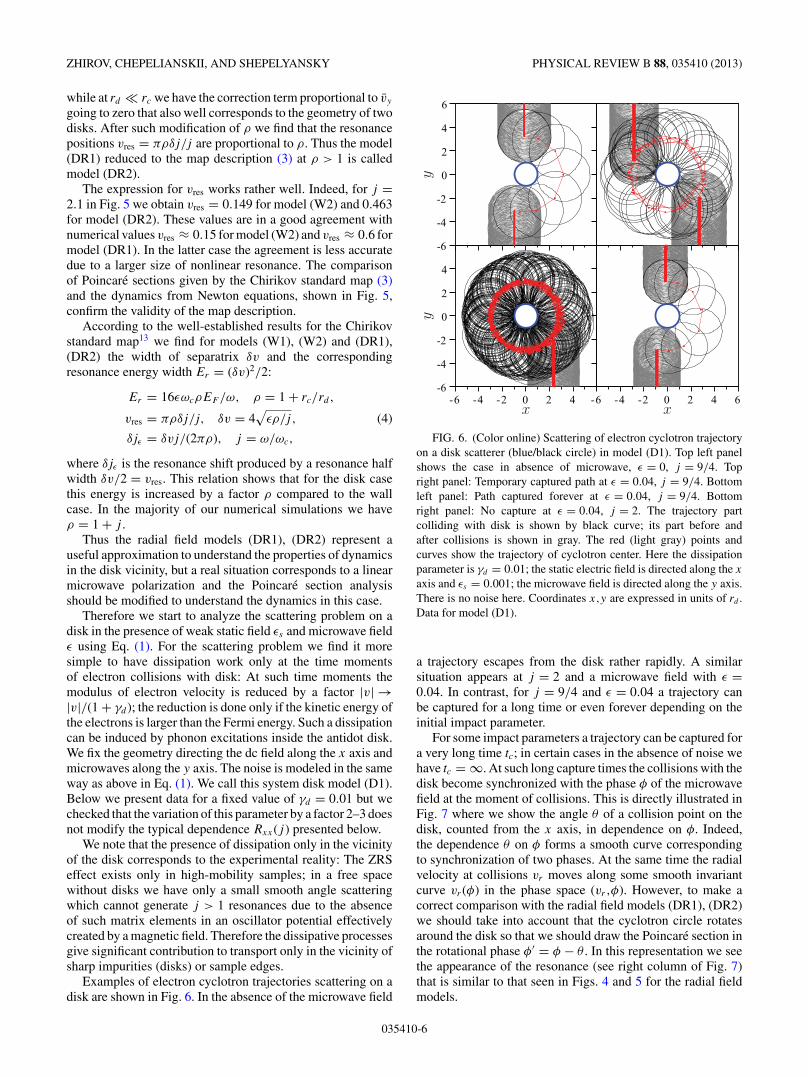
For some impact parameters a trajectory can be captured fora very long time tc; in certain cases in the absence of noise wehave tc = ∞. At such long capture times the collisions with thedisk become synchronized with the phase φ of the microwavefield at the moment of collisions. This is directly illustrated inFig. 7 where we show the angle θ of a collision point on thedisk, counted from the x axis, in dependence on φ. Indeed,the dependence θ on φ forms a smooth curve correspondingto synchronization of two phases. At the same time the radialvelocity at collisions vr moves along some smooth invariantcurve vr (φ) in the phase space (vr,φ). However, to make acorrect comparison with the radial field models (DR1), (DR2)we should take into account that the cyclotron circle rotatesaround the disk so that we should draw the Poincare section inthe rotational phase φ′ = φ − θ . In this representation we seethe appearance of the resonance (see right column of Fig. 7)that is similar to that seen in Figs. 4 and 5 for the radial fieldmodels.
035410-6
TOWARDS A SYNCHRONIZATION THEORY OF . . . PHYSICAL REVIEW B 88, 035410 (2013)
-1.0
-0.5
0.0
0.5
1.0
.
.
.
.
.
.
.
.
.
.
.
.
.
.
.
.
.
.
.
.
.
.
.
.
.
.
.
.
.
.
.
.
.
.
.
.
.
.
.
.
.
.
.
.
.
.
.
.
.
.
.
.
.
.
.
.
.
.
.
.
.
.
.
.
.
.
.
.
.
.
.
.
.
.
.
.
.
.
.
.
.
.
.
.
.
.
.
.
.
.
.
.
.
.
.
.
.
.
.
.
.
.
.
.
.
.
.
.
.
.
.
.
.
.
.
.
.
.
.
.
.
.
.
.
.
.
.
.
.
.
.
.
.
.
.
.
.
.
.
.
.
.
.
.
.
.
.
.
.
.
.
.
.
.
.
.
.
.
.
.
.
.
.
.
.
.
.
.
.
.
.
.
.
.
.
.
.
.
.
.
.
.
.
.
.
.
.
.
.
.
.
.
.
.
.
.
.
.
.
.
.
.
.
.
.
.
.
.
.
.
.
.
.
.
.
.
.
.
.
.
.
.
.
.
.
.
.
.
.
.
.
.
.
.
.
.
.
.
.
.
.
.
.
.
.
.
.
.
.
.
.
.
.
.
.
.
.
.
.
.
.
.
.
.
.
.
.
.
.
.
.
.
.
.
.
.
.
.
.
.
.
.
.
.
.
.
.
.
.
.
.
.
.
.
.
.
.
.
.
.
.
.
.
.
.
.
.
.
.
.
.
.
.
.
.
.
.
.
.
.
.
.
.
.
.
.
.
.
.
.
.
.
.
.
.
.
.
.
.
.
.
.
.
.
.
.
.
.
.
.
.
.
.
.
.
.
.
.
.
.
.
.
.
.
.
.
.
.
.
.
.
.
.
.
.
.
.
.
.
.
.
.
.
.
.
.
.
.
.
.
.
.
.
.
.
.
.
.
.
.
.
.
.
.
.
.
.
.
.
.
.
.
.
.
.
.
.
.
.
.
.
.
.
.
.
.
.
.
.
.
.
.
.
.
.
.
.
.
.
.
.
.
.
.
.
.
.
.
.
.
.
.
.
.
.
.
.
.
.
.
.
.
.
.
.
.
.
.
.
.
.
.
.
.
.
.
.
.
.
.
.
.
.
.
.
.
.
.
.
.
.
.
.
.
.
.
.
.
.
.
.
.
.
.
.
.
.
.
.
.
.
.
.
.
.
.
.
.
.
.
.
.
.
.
.
.
.
.
.
.
.
.
.
.
.
.
.
.
.
.
.
.
.
.
.
.
.
.
.
.
.
.
.
.
.
.
.
.
.
.
.
.
.
.
.
.
.
.
.
.
.
.
.
.
.
.
.
.
.
.
.
.
.
.
.
.
.
.
.
.
.
.
.
.
.
.
.
.
.
.
.
.
.
.
.
.
.
.
.
.
.
.
.
.
.
.
.
.
.
.
.
.
.
.
.
.
.
.
.
.
.
.
.
.
.
.
.
.
.
.
.
.
.
.
.
.
.
.
.
.
.
.
.
.
.
.
.
.
.
.
.
.
.
.
.
.
.
.
.
.
.
.
.
.
.
.
.
.
.
.
.
.
.
.
.
.
.
.
.
.
.
.
.
.
.
.
.
.
.
.
.
.
.
.
.
.
.
.
.
.
.
.
.
.
.
.
.
.
.
.
.
.
.
.
.
.
.
.
.
.
.
.
.
.
.
.
.
.
.
.
.
.
.
.
.
.
.
.
.
.
.
.
.
.
.
.
.
.
.
.
.
.
.
.
.
.
.
.
.
.
.
.
.
.
.
.
.
.
.
.
.
.
.
.
.
.
.
.
.
.
.
.
.
.
.
.
.
.
.
.
.
.
.
.
.
.
.
.
.
.
.
.
.
.
.
.
.
.
.
.
.
.
.
.
.
.
.
.
.
.
.
.
.
.
.
.
.
.
.
.
.
.
.
.
.
.
.
.
.
.
.
.
.
.
.
.
.
.
.
.
.
.
.
.
.
.
.
.
.
.
.
.
.
.
.
.
.
.
.
.
.
.
.
.
.
.
.
.
.
.
.
.
.
.
.
.
.
.
.
.
.
.
.
.
.
.
.
.
.
.
.
.
.
.
.
.
.
.
.
.
.
.
.
.
.
.
.
.
.
.
.
.
.
.
.
.
.
.
.
.
.
.
.
.
.
.
.
.
.
.
.
.
.
.
.
.
.
.
.
.
.
.
.
.
.
.
.
.
.
.
.
.
.
.
.
.
.
.
.
.
.
.
.
.
.
.
.
.
.
.
.
.
.
.
.
.
.
.
.
.
.
.
.
.
.
.
.
.
.
.
.
.
.
.
.
.
.
.
.
.
.
.
.
.
.
.
.
.
.
.
.
.
.
.
.
.
.
.
.
.
.
.
.
.
.
.
.
.
.
.
.
.
.
.
.
.
.
.
.
.
.
.
.
.
.
.
.
.
.
.
.
.
.
.
.
.
.
.
.
.
.
.
.
.
.
.
.
.
.
.
.
.
.
.
.
.
.
.
.
.
.
.
.
.
.
.
.
.
.
.
.
.
.
.
.
.
.
.
.
.
.
.
.
.
.
.
.
.
.
.
.
.
.
.
.
.
.
.
.
.
.
.
.
.
.
.
.
.
.
.
.
.
.
.
.
.
.
.
.
.
.
.
.
.
.
.
.
.
.
.
.
.
.
.
.
.
.
.
.
.
.
.
.
.
.
.
.
.
.
.
.
.
.
.
.
.
.
.
.
.
.
.
.
.
.
.
.
.
.
.
.
.
.
.
.
.
.
.
.
.
.
.
.
.
.
.
.
.
.
.
.
.
.
.
.
.
.
.
.
.
.
.
.
.
.
.
.
.
.
.
.
.
.
.
.
.
.
.
.
.
.
.
.
.
.
.
.
.
.
.
.
.
.
.
.
.
.
.
.
.
.
.
.
.
.
.
.
.
.
.
.
.
.
.
.
.
.
.
.
.
.
.
.
.
.
.
.
.
.
.
.
.
.
.
.
.
.
.
.
.
.
.
.
.
.
.
.
.
.
.
.
.
.
.
.
.
.
.
.
.
.
.
.
.
.
.
.
.
.
.
.
.
.
.
.
.
.
.
.
.
.
.
.
.
.
.
.
.
.
.
.
.
.
.
.
.
.
.
.
.
.
.
.
.
.
.
.
.
.
.
.
.
.
.
.
.
.
.
.
.
.
.
.
.
.
.
.
.
.
.
.
.
.
.
.
.
.
.
.
.
.
.
.
.
.
.
.
.
.
.
.
.
.
.
.
.
.
.
.
.
.
.
.
.
.
.
.
.
.
.
.
.
.
.
.
.
.
.
.
.
.
.
.
.
.
.
.
.
.
.
.
.
.
.
.
.
.
.
.
.
.
.
.
.
.
.
.
.
.
.
.
.
.
.
.
.
.
.
.
.
.
.
.
.
.
.
.
.
.
.
.
.
.
.
.
.
.
.
.
.
.
.
.
.
.
.
.
.
.
.
.
.
.
.
.
.
.
.
.
.
.
.
.
.
.
.
.
.
.
.
.
.
.
.
.
.
.
.
.
.
.
.
.
.
.
.
.
.
.
.
.
.
.
.
.
.
.
.
.
.
.
.
.
.
.
.
.
.
.
.
.
.
.
.
.
.
.
.
.
.
.
.
.
.
.
.
.
.
.
.
.
.
.
.
.
.
.
.
.
.
.
.
.
.
.
.
.
.
.
.
.
.
.
.
.
.
.
.
.
.
.
.
.
.
.
.
.
.
.
.
.
.
.
.
.
.
.
.
.
.
.
.
.
.
.
.
.
.
.
.
.
.
.
.
.
.
.
.
.
.
.
.
.
.
.
.
.
.
.
.
.
.
.
.
.
.
.
.
.
.
.
.
.
.
.
.
.
.
.
.
.
.
.
.
.
.
.
.
.
.
.
.
.
.
.
.
.
.
.
.
.
.
.
.
.
.
.
.
.
.
.
.
.
.
.
.
.
.
.
.
.
.
.
.
.
.
.
.
.
.
.
.
.
.
.
.
.
.
.
.
.
.
.
.
.
.
.
.
.
.
.
.
.
.
.
.
.
.
.
.
.
.
.
.
.
.
.
.
.
.
.
.
.
.
.
.
.
.
.
.
.
.
.
.
.
.
.
.
.
.
.
.
.
.
.
.
.
.
.
.
.
.
.
.
.
.
.
.
.
.
.
.
.
.
.
.
.
.
.
.
.
.
.
.
.
.
.
.
.
.
.
.
.
.
.
.
.
.
.
.
.
.
.
.
.
.
.
.
.
.
.
.
.
.
.
.
.
.
.
.
.
.
.
.
.
.
.
.
.
.
.
.
.
.
.
.
.
.
.
.
.
.
.
.
.
.
.
.
.
.
.
.
.
.
.
.
.
.
.
.
.
.
.
.
.
.
.
.
.
.
.
.
.
.
.
.
.
.
.
.
.
.
.
.
.
.
.
.
.
.
.
.
.
.
.
.
.
.
.
.
.
.
.
.
.
.
.
.
.
.
.
.
.
.
.
.
.
.
.
.
.
.
.
.
.
.
.
.
.
.
.
.
.
.
.
.
.
.
.
.
.
.
.
.
.
.
.
.
.
.
.
.
.
.
.
.
.
.
.
.
.
.
.
.
.
.
.
.
.
.
.
.
.
.
.
.
.
.
.
.
.
.
.
.
.
.
.
.
.
.
.
.
.
.
.
.
.
.
.
.
.
.
.
.
.
.
.
.
.
.
.
.
.
.
.
.
.
.
.
.
.
.
.
.
.
.
.
.
.
.
.
.
.
.
.
.
.
.
.
.
.
.
.
.
.
.
.
.
.
.
.
.
.
.
.
.
.
.
.
.
.
.
.
.
.
.
.
.
.
.
.
.
.
.
.
.
.
.
.
.
.
.
.
.
.
.
.
.
.
.
.
.
.
.
.
.
.
.
.
.
.
.
.
.
.
.
.
.
.
.
.
.
.
.
.
.
.
.
.
.
.
.
.
.
.
.
.
.
.
.
.
.
.
.
.
.
.
.
.
.
.
.
.
.
.
.
.
.
.
.
.
.
.
.
.
.
.
.
.
.
.
.
.
.
.
.
.
.
.
.
.
.
.
.
-1
0
1
.
.
.
.
.
.
.
.
.
.
.
.
.
.
.
.
.
.
.
.
.
.
.
.
.
.
.
.
.
.
.
.
.
.
.
.
.
.
.
.
.
.
.
.
.
.
.
.
.
.
.
.
.
.
.
.
.
.
.
.
.
.
.
.
.
.
.
.
.
.
.
.
.
.
.
.
.
.
.
.
.
.
.
.
.
.
.
.
.
.
.
.
.
.
.
.
.
.
.
.
.
.
.
.
.
.
.
.
.
.
.
.
.
.
.
.
.
.
.
.
.
.
.
.
.
.
.
.
.
.
.
.
.
.
.
.
.
.
.
.
.
.
.
.
.
.
.
.
.
.
.
.
.
.
.
.
.
.
.
.
.
.
.
.
.
.
.
.
.
.
.
.
.
.
.
.
.
.
.
.
.
.
.
.
.
.
.
.
.
.
.
.
.
.
.
.
.
.
.
.
.
.
.
.
.
.
.
.
.
.
.
.
.
.
.
.
.
.
.
.
.
.
.
.
.
.
.
.
.
.
.
.
.
.
.
.
.
.
.
.
.
.
.
.
.
.
.
.
.
.
.
.
.
.
.
.
.
.
.
.
.
.
.
.
.
.
.
.
.
.
.
.
.
.
.
.
.
.
.
.
.
.
.
.
.
.
.
.
.
.
.
.
.
.
.
.
.
.
.
.
.
.
.
.
.
.
.
.
.
.
.
.
.
.
.
.
.
.
.
.
.
.
.
.
.
.
.
.
.
.
.
.
.
.
.
.
.
.
.
.
.
.
.
.
.
.
.
.
.
.
.
.
.
.
.
.
.
.
.
.
.
.
.
.
.
.
.
.
.
.
.
.
.
.
.
.
.
.
.
.
.
.
.
.
.
.
.
.
.
.
.
.
.
.
.
.
.
.
.
.
.
.
.
.
.
.
.
.
.
.
.
.
.
.
.
.
.
.
.
.
.
.
.
.
.
.
.
.
.
.
.
.
.
.
.
.
.
.
.
.
.
.
.
.
.
.
.
.
.
.
.
.
.
.
.
.
.
.
.
.
.
.
.
.
.
.
.
.
.
.
.
.
.
.
.
.
.
.
.
.
.
.
.
.
.
.
.
.
.
.
.
.
.
.
.
.
.
.
.
.
.
.
.
.
.
.
.
.
.
.
.
.
.
.
.
.
.
.
.
.
.
.
.
.
.
.
.
.
.
.
.
.
.
.
.
.
.
.
.
.
.
.
.
.
.
.
.
.
.
.
.
.
.
.
.
.
.
.
.
.
.
.
.
.
.
.
.
.
.
.
.
.
.
.
.
.
.
.
.
.
.
.
.
.
.
.
.
.
.
.
.
.
.
.
.
.
.
.
.
.
.
.
.
.
.
.
.
.
.
.
.
.
.
.
.
.
.
.
.
.
.
.
.
.
.
.
.
.
.
.
.
.
.
.
.
.
.
.
.
.
.
.
.
.
.
.
.
.
.
.
.
.
.
.
.
.
.
.
.
.
.
.
.
.
.
.
.
.
.
.
.
.
.
.
.
.
.
.
.
.
.
.
.
.
.
.
.
.
.
.
.
.
.
.
.
.
.
.
.
.
.
.
.
.
.
.
.
.
.
.
.
.
.
.
.
.
.
.
.
.
.
.
.
.
.
.
.
.
.
.
.
.
.
.
.
.
.
.
.
.
.
.
.
.
.
.
.
.
.
.
.
.
.
.
.
.
.
.
.
.
.
.
.
.
.
.
.
.
.
.
.
.
.
.
.
.
.
.
.
.
.
.
.
.
.
.
.
.
.
.
.
.
.
.
.
.
.
.
.
.
.
.
.
.
.
.
.
.
.
.
.
.
.
.
.
.
.
.
.
.
.
.
.
.
.
.
.
.
.
.
.
.
.
.
.
.
.
.
.
.
.
.
.
.
.
.
.
.
.
.
.
.
.
.
.
.
.
.
.
.
.
.
.
.
.
.
.
.
.
.
.
.
.
.
.
.
.
.
.
.
.
.
.
.
.
.
.
.
.
.
.
.
.
.
.
.
.
.
.
.
.
.
.
.
.
.
.
.
.
.
.
.
.
.
.
.
.
.
.
.
.
.
.
.
.
.
.
.
.
.
.
.
.
.
.
.
.
.
.
.
.
.
.
.
.
.
.
.
.
.
.
.
.
.
.
.
.
.
.
.
.
.
.
.
.
.
.
.
.
.
.
.
.
.
.
.
.
.
.
.
.
.
.
.
.
.
.
.
.
.
.
.
.
.
.
.
.
.
.
.
.
.
.
.
.
.
.
.
.
.
.
.
.
.
.
.
.
.
.
.
.
.
.
.
.
.
.
.
.
.
.
.
.
.
.
.
.
.
.
.
.
.
.
.
.
.
.
.
.
.
.
.
.
.
.
.
.
.
.
.
.
.
.
.
.
.
.
.
.
.
.
.
.
.
.
.
.
.
.
.
.
.
.
.
.
.
.
.
.
.
.
.
.
.
.
.
.
.
.
.
.
.
.
.
.
.
.
.
.
.
.
.
.
.
.
.
.
.
.
.
.
.
.
.
.
.
.
.
.
.
.
.
.
.
.
.
.
.
.
.
.
.
.
.
.
.
.
.
.
.
.
.
.
.
.
.
.
.
.
.
.
.
.
.
.
.
.
.
.
.
.
.
.
.
.
.
.
.
.
.
.
.
.
.
.
.
.
.
.
.
.
.
.
.
.
.
.
.
.
.
.
.
.
.
.
.
.
.
.
.
.
.
.
.
.
.
.
.
.
.
.
.
.
.
.
.
.
.
.
.
.
.
.
.
.
.
.
.
.
.
.
.
.
.
.
.
.
.
.
.
.
.
.
.
.
.
.
.
.
.
.
.
.
.
.
.
.
.
.
.
.
.
.
.
.
.
.
.
.
.
.
.
.
.
.
.
.
.
.
.
.
.
.
.
.
.
.
.
.
.
.
.
.
.
.
.
.
.
.
.
.
.
.
.
.
.
.
.
.
.
.
.
.
.
.
.
.
.
.
.
.
.
.
.
.
.
.
.
.
.
.
.
.
.
.
.
.
.
.
.
.
.
.
.
.
.
.
.
.
.
.
.
.
.
.
.
.
.
.
.
.
.
.
.
.
.
.
.
.
.
.
.
.
.
.
.
.
.
.
.
.
.
.
.
.
.
.
.
.
.
.
.
.
.
.
.
.
.
.
.
.
.
.
.
.
.
.
.
.
.
.
.
.
.
.
.
.
.
.
.
.
.
.
.
.
.
.
.
.
.
.
.
.
.
.
.
.
.
.
.
.
.
.
.
.
.
.
.
.
.
.
.
.
.
.
.
.
.
.
.
.
.
.
.
.
.
.
.
.
.
.
.
.
.
.
.
.
.
.
.
.
.
.
.
.
.
.
.
.
.
.
.
.
.
.
.
.
.
.
.
.
.
.
.
.
.
.
.
.
.
.
.
.
.
.
.
.
.
.
.
.
.
.
.
.
.
.
.
.
.
.
.
.
.
.
.
.
.
.
.
.
.
.
.
.
.
.
.
.
.
.
.
.
.
.
.
.
.
.
.
.
.
.
.
.
.
.
.
.
.
.
.
.
.
.
.
.
.
.
.
.
.
.
.
.
.
.
.
.
.
.
.
.
.
.
.
.
.
.
.
.
.
.
.
.
.
.
.
.
.
.
.
.
.
.
.
.
.
.
.
.
.
.
.
.
.
.
.
.
.
.
.
.
.
.
.
.
.
.
.
.
.
.
.
.
.
.
.
.
.
.
.
.
.
.
.
.
.
.
.
.
.
.
.
.
.
.
.
.
.
.
.
.
.
.
.
.
.
.
.
.
.
.
.
.
.
.
.
.
.
.
.
.
.
.
.
.
.
.
.
.
.
.
.
.
.
.
.
.
.
.
.
.
.
.
.
.
.
.
.
.
.
.
.
.
.
.
.
.
.
.
.
.
.
.
.
.
.
.
.
.
.
.
.
.
.
.
.
.
.
.
.
.
.
.
.
.
.
.
.
.
.
.
.
.
.
.
.
.
.
.
.
.
.
.
.
.
.
.
.
.
.
.
.
.
.
.
.
.
.
.
.
.
.
.
.
.
.
.
.
.
.
.
.
.
.
.
.
.
.
.
.
.
.
.
.
.
.
.
.
.
.
.
.
.
.
.
.
.
.
.
.
.
.
.
.
.
.
.
.
.
.
.
.
.
.
.
.
.
.
.
.
.
.
.
.
.
.
.
.
.
.
.
.
.
.
.
.
.
.
.
.
.
.
.
.
.
.
.
.
.
.
.
.
.
.
.
.
.
.
.
.
.
.
.
.
.
.
.
.
.
.
.
.
.
.
.
.
.
.
.
.
.
.
.
.
.
.
.
.
.
.
.
.
.
.
.
.
.
.
.
.
.
.
.
.
.
.
.
.
.
.
.
.
.
.
.
.
.
.
.
.
.
.
.
.
.
.
.
.
.
.
.
.
.
.
.
.
.
.
.
.
.
.
.
.
.
.
.
.
.
.
.
.
.
.
.
.
.
.
.
.
.
.
.
.
.
.
.
.
.
.
.
.
.
.
.
.
.
.
.
.
.
.
.
.
.
.
.
.
.
.
.
.
.
.
.
.
.
.
.
.
.
.
.
.
.
.
.
.
.
.
.
.
.
.
.
.
.
.
.
.
.
.
.
.
.
.
.
.
.
.
.
.
.
.
.
.
.
.
.
.
.
.
.
.
.
.
.
.
.
.
.
.
.
.
.
.
.
.
.
.
.
.
.
.
.
.
.
.
.
.
.
.
.
.
.
.
.
.
.
.
.
.
.
.
.
.
.
.
.
.
.
.
.
.
.
.
.
.
.
.
.
.
.
.
.
.
.
.
.
.
.
.
.
.
.
.
.
.
.
.
.
.
.
.
.
.
.
.
.
.
.
.
.
.
.
.
.
.
.
.
.
.
.
.
.
.
.
.
.
.
.
.
.
.
.
.
.
.
.
.
.
.
.
.
.
.
.
.
.
.
.
.
.
.
.
.
.
.
.
.
.
.
.
.
.
.
.
.
.
.
.
.
.
.
.
.
.
.
.
.
.
.
0.0
0.5
1.0
-1.0 -0.5 0.0 0.5 1.0
..
.
.
. .
.
.
.
.
.
.
.
. .
.
.
..
.
.
.
..
.
.
. .
.
.
.
.
.
.
.
..
.
.
. .
.
.
.
. .
.
.
..
.
.
.
..
.
.
..
.
.
.
..
.
.
. .
.
.
..
.
.
.
..
.
.
..
.
.
.
.
.
.
.
..
.
.
..
.
.
.
. .
.
.
..
.
.
.
..
.
.
..
.
.
.
..
.
.
. .
.
.
.
..
.
.
. .
.
.
.
.
.
.
.
..
.
.
.
.
.
.
. ..
.
.
. .
.
.
.
..
.
.
. .
.
.
.
.
.
.
.
. .
.
.
..
.
.
.
..
.
.
. .
.
.
.
.
.
.
.
. .
.
.
..
.
.
.
..
.
.
..
.
.
.
.
.
.
.
. .
.
.
.
.
.
.
.
. .
.
.
. .
.
.
.
..
.
.
. .
.
.
..
.
.
.
. .
.
.
.
.
.
.
.
. .
.
.
..
.
.
.
..
.
.
..
.
.
..
.
.
.
. .
.
.
.
..
.
.
..
.
.
..
.
.
.
. .
.
.
..
.
.
.
..
.
.
..
.
.
.
..
.
.
. .
.
.
.
.
.
.
.
. .
.
.
.
.
.
.
.
. .
.
.
..
.
.
.
..
.
.
. .
.
.
..
.
.
.
. .
.
.
..
.
.
.
..
.
.
. .
.
.
.
.
.
.
.
..
.
.
. .
.
.
.
..
.
.
...
.
.
.
.
.
.
..
.
.
.
..
.
.
..
.
.
.
.
.
.
.
. .
.
.
. ..
.
.
..
.
.
..
.
.
.
.
.
.
.
. .
.
.
..
.
.
.
..
.
.
.
.
.
.
.
..
.
.
. .
.
.
.
.
.
.
.
..
.
.
..
.
.
.
. .
.
.
. .
.
.
.
..
.
.
. .
.
.
.
.
.
.
.
. .
.
.
. .
.
.
.
..
.
.
...
.
.
.
.
.
.
.
.
.
.
..
.
.
.
. .
.
.
..
.
.
.
..
.
.
..
.
.
.
.
.
.
.
. .
.
.
.
..
.
.
..
.
.
.
.
.
.
.
..
.
.
. .
.
.
..
.
.
.
. .
.
.
.
.
.
.
.
..
.
.
..
.
.
.
..
.
.
. .
.
.
.
.
.
.
.
. .
.
.
..
.
.
.
..
.
.
..
.
.
.
..
.
.
. .
.
.
..
.
.
.
. .
.
.
..
.
.
.
..
.
.
..
.
.
.
..
.
.
. .
.
.
.
.
.
.
.
..
.
.
.
.
.
.
.
. .
.
.
. .
.
.
.
..
.
.
. .
.
.
.
.
.
.
.
..
.
.
..
.
.
.
. .
.
.
. .
.
.
.
.
.
.
.
..
.
.
. .
.
.
.
. .
.
.
..
.
.
.
..
.
.
..
.
.
..
.
.
.
. .
.
.
..
.
.
.
.
.
.
.
..
.
.
..
.
.
.
. .
.
.
..
.
.
.
..
.
.
. .
.
.
.
..
.
.
. .
.
.
.
.
.
.
.
. .
.
.
..
.
.
.
..
.
.
. .
.
.
.
..
.
.
. .
.
.
..
.
.
.
. .
.
.
..
.
.
.
..
.
.
. .
.
.
.
..
.
.
. .
.
.
..
.
.
.
..
.
.
.
.
.
.
.
..
.
.
. .
.
.
.
..
.
.
..
.
.
.
.
.
.
.
..
.
.
.
.
.
.
.
. .
.
.
..
.
.
.
..
.
.
. .
.
.
..
.
.
.
. .
.
.
.
..
.
.
..
.
.
.
.
.
.
.
. .
.
.
..
.
.
.
. .
.
.
..
.
.
.
..
.
.
. .
.
.
.
.
.
.
.
..
.
.
..
.
.
.
..
.
.
..
.
.
.
..
.
.
. .
.
.
.
..
.
.
. .
.
.
.
..
.
.
..
.
.
. .
.
.
.
. .
.
.
..
.
.
.
.
.
.
.
. .
.
.
.
..
.
.
. .
.
.
..
.
.
.
..
.
.
..
.
.
..
.
.
.
. .
.
.
.
..
.
.
..
.
.
.
.
.
.
.
..
.
.
..
.
.
.
..
.
.
. .
.
.
.
..
.
.
..
.
.
..
.
.
.
..
.
.
. .
.
.
.
.
.
.
.
. .
.
.
.
.
.
.
.
. .
.
.
. .
.
.
.
..
.
.
. .
.
.
.
.
.
.
.
. .
.
.
..
.
.
.
..
.
.
..
.
.
.
.
.
.
.
..
.
.
. .
.
.
.
..
.
.
. .
.
.
. .
.
.
.
. .
.
.
..
.
.
..
.
.
.
..
.
.
.
..
.
.
. .
.
.
..
.
.
.
..
.
.
..
.
.
.
.
.
.
.
. .
.
.
.
..
.
.
. .
.
.
..
.
.
.
..
.
.
..
.
.
.
..
.
.
. .
.
.
.
..
.
.
. .
.
.
..
.
.
.
. .
.
.
..
.
.
.
..
.
.
. .
.
.
.
.
.
.
.
. .
.
.
..
.
.
.
..
.
.
..
.
.
.
.
.
.
.
..
.
.
..
.
.
.
..
.
.
.
.
.
.
.
.
.
.
.
..
.
.
..
.
.
.
..
.
.
.
..
.
..
.
.
.
. .
.
.
.
..
.
.
. .
.
.
.
.
.
.
.
..
.
.
..
.
.
.
. .
.
.
. .
.
.
.
..
.
.
..
.
.
.
.
.
.
.
. .
.
.
..
.
.
.
..
.
.
. .
.
.
.
.
.
.
.. .
.
.
. .
.
.
.
..
.
.
. .
.
.
.
.
.
.
.
. .
.
.
..
.
.
.
. .
.
.
. .
.
.
.
.
.
.
.
..
.
.
..
.
.
.
. .
.
.
.
..
.
.
..
.
.
.
.
.
.
.
..
.
.
. .
.
.
.
.
.
.
.
. .
.
.
.
.
.
.
.
..
.
.
.
.
.
.
.
. .
.
.
..
.
.
.
.
.
.
.
. .
.
.
.
.
.
.
.
. .
.
.
. .
.
.
.
.
.
.
.
. .
.
.
..
.
.
.
. .
.
.
..
.
.
.
..
.
.
. .
.
.
.
.
.
.
.
. .
.
.
. .
.
.
.
. .
.
.
..
.
.
.
..
.
.
..
.
.
.
..
.
.
. .
.
.
..
.
.
.
..
.
.
.
..
.
..
.
.
.
. .
.
.
.
..
.
..
.
.
.
..
.
.
.
..
.
.
. .
.
.
.
.
.
.
.
. .
.
.
.
.
.
.
.
. .
.
.
..
.
.
.
..
.
.
..
.
.
..
.
.
.
. .
.
.
.
.
.
.
.
. .
.
.
..
.
.
.
. .
.
.
. .
.
.
.
..
.
.
. .
.
.
.
.
.
.
.
. .
.
.
..
.
.
.
. .
.
.
..
.
.
.
..
.
.
. .
.
.
.
..
.
.
. .
.
.
.
.
.
.
.
. .
.
.
. .
.
.
.
.
.
.
.
. .
.
.
.
.
.
.
.
. .
.
.
. .
.
.
.
..
.
.
. .
.
.
..
.
.
.
.
.
.
.
.
.
.
.
. ..
.
.
. .
.
.
.
..
.
.
..
.
.
..
.
.
.
..
.
.
. .
.
.
.
.
.
.
.
. .
.
.
.
..
.
.
..
.
.
.
.
.
.
.
..
.
.
..
.
.
.
..
.
.
. .
.
.
.
..
.
..
.
.
.
.
.
.
.
.
..
.
.
..
.
.
.
..
.
.
..
.
.
.
..
.
..
.
.
.
..
.
.
.
..
.
.
. .
.
.
.
.
.
.
.
. .
.
.
..
.
.
.
. .
.
.
..
.
.
.
..
.
.
. .
.
.
..
.
.
.
..
.
.
.
..
.
.
..
.
.
..
.
.
.
..
.
.
..
.
.
.
.
.
.
.
..
.
.
.
.
.
.
..
.
.
.
. .
.
.
.
..
.
.
..
.
.
.
.
.
.
.
..
.
.
..
.
.
.
..
.
.
. .
.
.
.
..
.
.
. .
.
.
..
.
.
.
. .
.
.
..
.
.
.
..
.
.
..
.
.
.
..
.
.
. .
.
.
..
.
.
.
. .
.
.
..
.
.
.
. .
.
.
. .
.
.
.
..
.
.
..
.
.
..
.
.
.
. .
.
.
.
..
.
.
..
.
.
.
.
.
.
.
. .
.
.
. .
.
.
.
.
.
.
.
..
.
.
.
.
.
.
.
..
.
. .
0.0
0.5
1.0
-1.0 -0.5 0.0 0.5 1.0
..
.
.
..
.
.
.
.
.
.
.
. .
.
.
..
.
.
.
..
.
.
. .
.
.
.
.
.
.
.
..
.
.
. .
.
.
.
. .
.
.
..
.
.
.
..
.
.
..
.
.
.
..
.
.
..
.
.
..
.
.
.
..
.
.
..
.
.
.
.
.
.
.
..
.
.
..
.
.
.
..
.
.
..
.
.
.
..
.
.
..
.
.
.
..
.
.
. .
.
.
.
..
.
.
..
.
.
.
.
.
.
.
..
.
.
.
.
.
.
. ..
.
.
. .
.
.
.
. .
.
.
..
.
.
.
.
.
.
.
. .
.
.
..
.
.
.
..
.
.
. .
.
.
.
.
.
.
.
..
.
.
..
.
.
.
. .
.
.
..
.
.
.
.
.
.
.
. .
.
.
.
.
.
.
.
..
.
.
. .
.
.
.
..
.
.
..
.
.
..
.
.
.
. .
.
.
.
.
.
.
.
..
.
.
..
.
.
.
..
.
.
..
.
.
..
.
.
.
. .
.
.
.
..
.
.
..
.
.
..
.
.
.
. .
.
.
..
.
.
.
..
.
.
..
.
.
.
..
.
.
..
.
.
.
.
.
.
.
. .
.
.
.
.
.
.
.
..
.
.
..
.
.
.
. .
.
.
..
.
.
..
.
.
.
. .
.
.
..
.
.
.
..
.
.
. .
.
.
.
.
.
.
.
..
.
.
. .
.
.
.
. .
.
.
.. .
.
.
.
.
.
.
..
.
.
.
..
.
.
..
.
.
.
.
.
.
.
. .
.
.
...
.
.
..
.
.
..
.
.
.
.
.
.
.
..
.
.
..
.
.
.
..
.
.
.
.
.
.
.
..
.
.
. .
.
.
.
.
.
.
.
..
.
.
..
.
.
.
. .
.
.
..
.
.
.
..
.
.
. .
.
.
.
.
.
.
.
..
.
.
. .
.
.
.
..
.
.
.. .
.
.
.
.
.
.
.
.
.
.
..
.
.
.
..
.
.
..
.
.
.
..
.
.
..
.
.
.
.
.
.
.
. .
.
.
.
..
.
.
..
.
.
.
.
.
.
.
. .
.
.
..
.
.
..
.
.
.
. .
.
.
.
.
.
.
.
..
.
.
..
.
.
.
. .
.
.
..
.
.
.
.
.
.
.
. .
.
.
..
.
.
.
..
.
.
..
.
.
.
..
.
.
..
.
.
..
.
.
.
. .
.
.
..
.
.
.
..
.
.
..
.
.
.
. .
.
.
..
.
.
.
.
.
.
.
..
.
.
.
.
.
.
.
..
.
.
. .
.
.
.
. .
.
.
..
.
.
.
.
.
.
.
..
.
.
..
.
.
.
..
.
.
. .
.
.
.
.
.
.
.
..
.
.
. .
.
.
.
. .
.
.
..
.
.
.
..
.
.
..
.
.
..
.
.
.
..
.
.
..
.
.
.
.
.
.
.
..
.
.
..
.
.
.
. .
.
.
..
.
.
.
..
.
.
. .
.
.
.
. .
.
.
..
.
.
.
.
.
.
.
. .
.
.
..
.
.
.
..
.
.
. .
.
.
.
..
.
.
..
.
.
..
.
.
.
. .
.
.
..
.
.
.
..
.
.
. .
.
.
.
. .
.
.
..
.
.
..
.
.
.
..
.
.
.
.
.
.
.
..
.
.
. .
.
.
.
..
.
.
..
.
.
.
.
.
.
.
..
.
.
.
.
.
.
.
..
.
.
..
.
.
.
..
.
.
..
.
.
..
.
.
.
. .
.
.
.
..
.
.
..
.
.
.
.
.
.
.
. .
.
.
..
.
.
.
..
.
.
..
.
.
.
..
.
.
..
.
.
.
.
.
.
.
..
.
.
..
.
.
.
..
.
.
..
.
.
.
..
.
.
..
.
.
.
..
.
.
. .
.
.
.
..
.
.
..
.
.
. .
.
.
.
. .
.
.
..
.
.
.
.
.
.
.
. .
.
.
.
..
.
.
..
.
.
..
.
.
.
..
.
.
..
.
.
..
.
.
.
. .
.
.
.
. .
.
.
..
.
.
.
.
.
.
.
..
.
.
..
.
.
.
..
.
.
. .
.
.
.
..
.
.
..
.
.
..
.
.
.
..
.
.
..
.
.
.
.
.
.
.
. .
.
.
.
.
.
.
.
..
.
.
. .
.
.
.
. .
.
.
..
.
.
.
.
.
.
.
. .
.
.
..
.
.
.
..
.
.
..
.
.
.
.
.
.
.
..
.
.
. .
.
.
.
..
.
.
..
.
.
. .
.
.
.
. .
.
.
..
.
.
..
.
.
.
..
.
.
.
..
.
.
..
.
.
..
.
.
.
..
.
.
..
.
.
.
.
.
.
.
. .
.
.
.
..
.
.
..
.
.
..
.
.
.
..
.
.
..
.
.
.
..
.
.
. .
.
.
.
..
.
.
..
.
.
..
.
.
.
. .
.
.
..
.
.
.
..
.
.
. .
.
.
.
.
.
.
.
..
.
.
..
.
.
.
. .
.
.
..
.
.
.
.
.
.
.
..
.
.
..
.
.
.
..
.
.
.
.
.
.
.
.
.
.
.
..
.
.
..
.
.
.
..
.
.
.
..
.
..
.
.
.
. .
.
.
.
. .
.
.
..
.
.
.
.
.
.
.
..
.
.
..
.
.
.
..
.
.
. .
.
.
.
. .
.
.
..
.
.
.
.
.
.
.
. .
.
.
..
.
.
.
..
.
.
. .
.
.
.
.
.
.
...
.
.
. .
.
.
.
. .
.
.
..
.
.
.
.
.
.
.
. .
.
.
..
.
.
.
..
.
.
. .
.
.
.
.
.
.
.
..
.
.
..
.
.
.
. .
.
.
.
..
.
.
..
.
.
.
.
.
.
.
..
.
.
..
.
.
.
.
.
.
.
. .
.
.
.
.
.
.
.
..
.
.
.
.
.
.
.
. .
.
.
..
.
.
.
.
.
.
.
. .
.
.
.
.
.
.
.
..
.
.
. .
.
.
.
.
.
.
.
..
.
.
..
.
.
.
. .
.
.
..
.
.
.
..
.
.
. .
.
.
.
.
.
.
.
..
.
.
. .
.
.
.
. .
.
.
..
.
.
.
..
.
.
..
.
.
.
..
.
.
..
.
.
..
.
.
.
..
.
.
.
..
.
..
.
.
.
. .
.
.
.
. .
.
..
.
.
.
..
.
.
.
..
.
.
..
.
.
.
.
.
.
.
. .
.
.
.
.
.
.
.
..
.
.
..
.
.
.
..
.
.
..
.
.
..
.
.
.
. .
.
.
.
.
.
.
.
..
.
.
..
.
.
.
. .
.
.
..
.
.
.
..
.
.
. .
.
.
.
.
.
.
.
..
.
.
..
.
.
.
. .
.
.
..
.
.
.
..
.
.
. .
.
.
.
. .
.
.
..
.
.
.
.
.
.
.
. .
.
.
..
.
.
.
.
.
.
.
. .
.
.
.
.
.
.
.
..
.
.
. .
.
.
.
..
.
.
..
.
.
..
.
.
.
.
.
.
.
.
.
.
.
. ..
.
.
. .
.
.
.
. .
.
.
..
.
.
..
.
.
.
. .
.
.
..
.
.
.
.
.
.
.
. .
.
.
.
..
.
.
..
.
.
.
.
.
.
.
..
.
.
..
.
.
.
..
.
.
. .
.
.
.
..
.
..
.
.
.
.
.
.
.
.
..
.
.
..
.
.
.
..
.
.
..
.
.
.
..
.
..
.
.
.
..
.
.
.
..
.
.
..
.
.
.
.
.
.
.
. .
.
.
..
.
.
.
..
.
.
..
.
.
.
..
.
.
..
.
.
..
.
.
.
..
.
.
.
..
.
.
..
.
.
..
.
.
.
. .
.
.
..
.
.
.
.
.
.
.
..
.
.
.
.
.
.
..
.
.
.
. .
.
.
.
. .
.
.
..
.
.
.
.
.
.
.
..
.
.
..
.
.
.
..
.
.
. .
.
.
.
..
.
.
..
.
.
..
.
.
.
. .
.
.
..
.
.
.
..
.
.
..
.
.
.
. .
.
.
..
.
.
..
.
.
.
. .
.
.
..
.
.
.
..
.
.
. .
.
.
.
..
.
.
..
.
.
..
.
.
.
. .
.
.
.
. .
.
.
..
.
.
.
.
.
.
.
. .
.
.
..
.
.
.
.
.
.
.
..
.
.
.
.
.
.
.
..
.
..
θ/π
v r/v
0
φ/π φ /π
FIG. 7. Synchronization between disk collision angle θ andmicrowave phase φ. Left column: Dependence of angle θ of collisionpoint on disk, counted from x axis, and radial velocity vr , takenat collision, on microwave phase φ. Right column: Same as inleft column with φ′ = φ − θ . Here j = 2.25, ε = 0.04, εs = 0.001,γd = 0.01, v0 = vF , there is no noise; points are shown for times104/ω < t < 105/ω, the capture time of this orbit is tc > 105/ω.Data for model (D1).
A more direct correspondence between radial field models(DR1), (DR2) and model (D1) with a linearly polarizedmicrowave field is well seen from the Poincare sections shownin the rotation frame of phase φ′ = φ − θ in Fig. 8. In thisframe we see directly the resonance at j = 2.1,2.25 being verysimilar to the wall case and the radial field model. However, thepositions of resonance at vr = vres are different from those inFig. 5. Of course in the rotation frame the orbital momentumis only approximately conserved that gives a broadening ofinvariant curves in Fig. 8.
We explain this as follows. For the linear polarized fieldof model (D1) the radial component of the microwave field isproportional to εr ∼ ε sin θ cos ωt ∼ 0.5ε sin(ωt − θ ) wherewe kept only the slow frequency component of the radial field[the neglected term with sin(ωt + θ ) gives resonant valuesvres > vF ]. The radial field εr gives kicks to the radial velocitycomponent at collisions with the disk similar to the caseof model (DR2) described by Eq. (3): vr = vr + 0.5ε sin φ′,φ′ = φ′ + (2πj − 2vr j/ρ) − 2vr (ρ − 1)/ρ. Here we use theradial field component phase φ′ = ωt − θ at a moment ofcollision with the disk (the tangent component does not changevr and can be neglected). The phase variation φ′ − φ′ hasthe first term 2πj − 2vr j/ρ being the same as for the radialfield model (DR2), and an additional term related to rotationaround the disk with − θ = −2vr (ρ − 1)/ρ which comesfrom geometry. Indeed, the segment angles of intersectionsof circles rd and rc are as follows: For disk radius rd it is θ = 2vr (ρ − 1)/ρ and for cyclotron radius rc it is ϕ =2vr/ρ. Thus, their ratio is θ/ ϕ = rc/rd in agreement withthe geometrical scaling. This result can be obtained from the
0.0
0.4
0.8
0.0
0.4
0.8
0.0
0.4
0.8
-1 0 1 -1 0 1
v rv r
v r
φ /π φ /π
FIG. 8. Poincare sections in phase plane (vr ,φ′) with φ′ = φ −
θ for j = 2.1, ε = 0.01 (left top); j = 2.25, ε = 0.01 (right top);j = 2.75, ε = 0.02 (left middle); j = 2.25, ε = 0.02 (right middle);j = 2.75, ε = 0.04 (left bottom); j = 2.25, ε = 0.04 (right bottom);vr is expressed in units of vF . Data for model (D1), no noise nodissipation.
expression for ϕ by interchange of two disks that gives theabove expression for θ [at rd = rc both shifts ϕ = 2vr/ρ
and θ = 2vr (ρ − 1)/ρ are equal].Thus again the dynamical description is reduced down to
the Chirikov standard map with slightly modified parametersgiving us for the model (D1) the chaos parameter K = 2ε(j +ρ − 1)/ρ being usually smaller than unity, resonance positionvres, resonance width δv, and the resonance energy width Er =(δv)2/2:
Er = 8ερEF /(ρ + j − 1), ρ = 1 + rc/rd,
vres = πρδj/(j + ρ − 1), δv = 4√
ερ/(2(j + ρ − 1)),
δjε = δv(ρ + j − 1)/(2πρ), j = ω/ωc, (5)
where δjε is a shift of resonance produced by a finite separatrixhalf width δv/2. For our numerical simulations we have ρ =1 + j with vres = π (j + 1)δj/(2j ), δv = 2
√ε(j + 1)/j , and
δjε = (2/π )√
εj/(j + 1).At ρ = j + 1 Eq. (5) gives the values vres = 0.232 at
j = 2.1 while the numerical data of Fig. 8 give vres ≈ 0.2,and we have at j = 2.25 the theory value vres = 0.567 beingin good agreement with the numerical value vres ≈ 0.5 ofFig. 8. For j = 2.75 we have the resonance position at vr < 0corresponding to the bulk and thus the resonance is absent.The resonance width in Fig. 8 at j = 2.25, ε = 0.01 can beestimated as δv ≈ 0.3 that is in satisfactory agreement withthe theoretical value δv = 0.24 from (5). We recall that inmodel (D1) we have only approximate conservation of orbitalmomentum that gives a broadening of invariant curves andmakes determination of the resonance width less accurate. Inspite of this broadening we see that the resonance descriptionby the Chirikov standard map works rather well.
035410-7
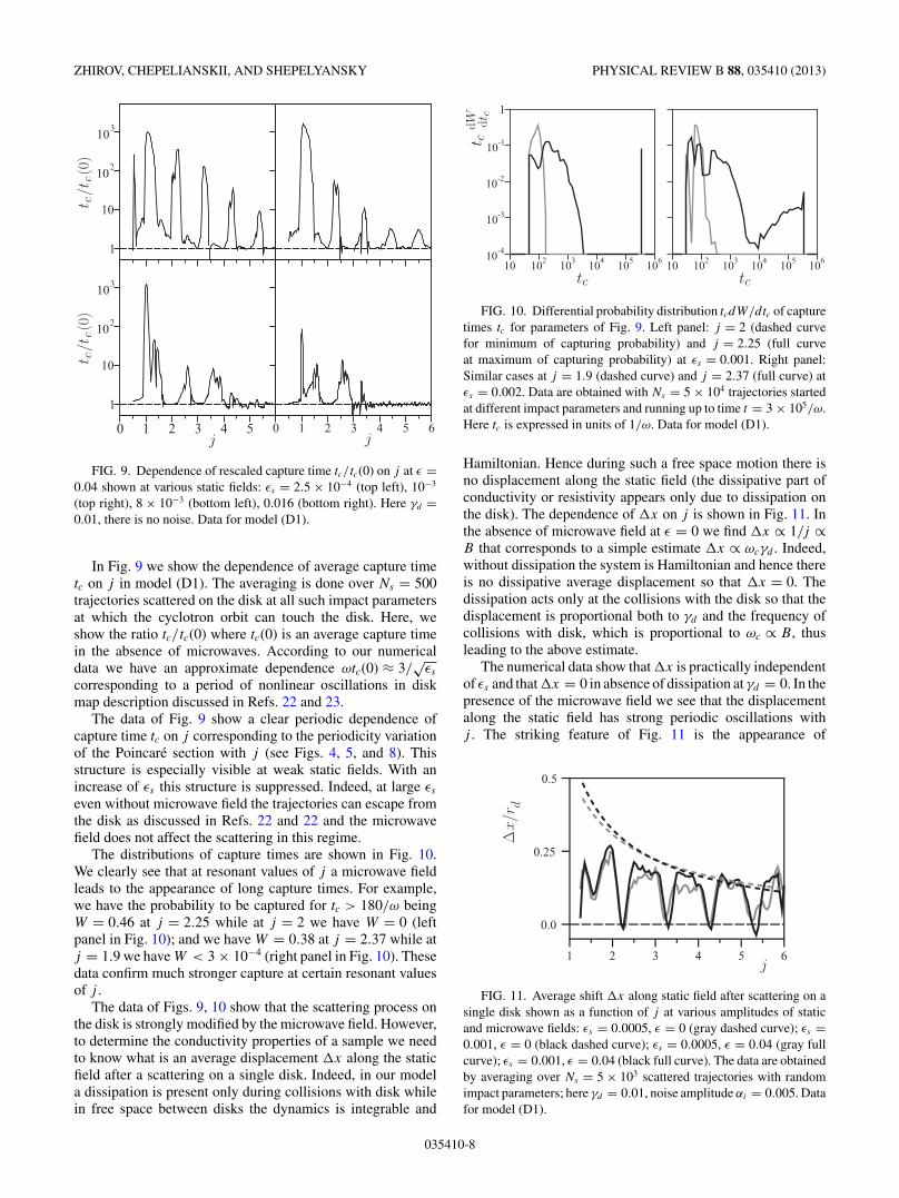
ZHIROV, CHEPELIANSKII, AND SHEPELYANSKY PHYSICAL REVIEW B 88, 035410 (2013)
1
10
102
103
1
10
102
103
0 1 2 3 4 5 0 1 2 3 4 5 6
t c/t
c(0
)t c
/tc(0
)
j j
FIG. 9. Dependence of rescaled capture time tc/tc(0) on j at ε =0.04 shown at various static fields: εs = 2.5 × 10⁻⁴ (top left), 10−3
(top right), 8 × 10⁻³ (bottom left), 0.016 (bottom right). Here γd =0.01, there is no noise. Data for model (D1).
In Fig. 9 we show the dependence of average capture timetc on j in model (D1). The averaging is done over Ns = 500trajectories scattered on the disk at all such impact parametersat which the cyclotron orbit can touch the disk. Here, weshow the ratio tc/tc(0) where tc(0) is an average capture timein the absence of microwaves. According to our numericaldata we have an approximate dependence ωtc(0) ≈ 3/
√εs
corresponding to a period of nonlinear oscillations in diskmap description discussed in Refs. 22 and 23.
The data of Fig. 9 show a clear periodic dependence ofcapture time tc on j corresponding to the periodicity variationof the Poincare section with j (see Figs. 4, 5, and 8). Thisstructure is especially visible at weak static fields. With anincrease of εs this structure is suppressed. Indeed, at large εs
even without microwave field the trajectories can escape fromthe disk as discussed in Refs. 22 and 22 and the microwavefield does not affect the scattering in this regime.
The distributions of capture times are shown in Fig. 10.We clearly see that at resonant values of j a microwave fieldleads to the appearance of long capture times. For example,we have the probability to be captured for tc > 180/ω beingW = 0.46 at j = 2.25 while at j = 2 we have W = 0 (leftpanel in Fig. 10); and we have W = 0.38 at j = 2.37 while atj = 1.9 we have W < 3 × 10⁻⁴ (right panel in Fig. 10). Thesedata confirm much stronger capture at certain resonant valuesof j .
The data of Figs. 9, 10 show that the scattering process onthe disk is strongly modified by the microwave field. However,to determine the conductivity properties of a sample we needto know what is an average displacement x along the staticfield after a scattering on a single disk. Indeed, in our modela dissipation is present only during collisions with disk whilein free space between disks the dynamics is integrable and
10-4
10-3
10-2
10-1
1
10 102 103 104 105 106 10 102 103 104 105 106
t cdW dt c
tc tc
FIG. 10. Differential probability distribution tcdW/dtc of capturetimes tc for parameters of Fig. 9. Left panel: j = 2 (dashed curvefor minimum of capturing probability) and j = 2.25 (full curveat maximum of capturing probability) at εs = 0.001. Right panel:Similar cases at j = 1.9 (dashed curve) and j = 2.37 (full curve) atεs = 0.002. Data are obtained with Ns = 5 × 10⁴ trajectories startedat different impact parameters and running up to time t = 3 × 10⁵/ω.Here tc is expressed in units of 1/ω. Data for model (D1).
Hamiltonian. Hence during such a free space motion there isno displacement along the static field (the dissipative part ofconductivity or resistivity appears only due to dissipation onthe disk). The dependence of x on j is shown in Fig. 11. Inthe absence of microwave field at ε = 0 we find x ∝ 1/j ∝B that corresponds to a simple estimate x ∝ ωcγd . Indeed,without dissipation the system is Hamiltonian and hence thereis no dissipative average displacement so that x = 0. Thedissipation acts only at the collisions with the disk so that thedisplacement is proportional both to γd and the frequency ofcollisions with disk, which is proportional to ωc ∝ B, thusleading to the above estimate.
The numerical data show that x is practically independentof εs and that x = 0 in absence of dissipation at γd = 0. In thepresence of the microwave field we see that the displacementalong the static field has strong periodic oscillations withj . The striking feature of Fig. 11 is the appearance of
0.0
0.25
0.5
1 2 3 4 5 6
Δx/r
d
j
FIG. 11. Average shift x along static field after scattering on asingle disk shown as a function of j at various amplitudes of staticand microwave fields: εs = 0.0005, ε = 0 (gray dashed curve); εs =0.001, ε = 0 (black dashed curve); εs = 0.0005, ε = 0.04 (gray fullcurve); εs = 0.001, ε = 0.04 (black full curve). The data are obtainedby averaging over Ns = 5 × 10³ scattered trajectories with randomimpact parameters; here γd = 0.01, noise amplitude αi = 0.005. Datafor model (D1).
035410-8

TOWARDS A SYNCHRONIZATION THEORY OF . . . PHYSICAL REVIEW B 88, 035410 (2013)
windows of zero displacement x ≈ 0 at resonance valuesjr = 9/4,13/4,17/4, . . . . We discuss how this scattering ona single disk modifies the resistance of a sample with a largenumber of disks in the next section.
IV. RESISTANCE OF SAMPLES WITH MANY DISKS
To determine a resistance of a sample with many diskswe use the following scattering disk model. The scatteringon a single disk in a static electric field εs is computedas described in the previous section with a random impactparameter inside the collision cross section σd = 2(rc + rd ).After that a trajectory evolves along the y axis according tothe exact solution of Hamiltonian Eq. (1) (no dissipation andno noise) up to a collision with the next disk which is takenrandomly on a distance between 2(rc + rd ) and 2e wheree = 1/(σdnd ) is a mean-free path along the y axis and nd is atwo-dimensional density of disks [of course e � 2(rc + rd )].In the vicinity of the disk the dynamical evolution is obtainedwith the Runge-Kutta solution of dynamical equations aswas the case in the previous section. We use a low diskdensity with ndr
2d ∼ 1/100. The collision with the disk is
done with a random impact parameter on the x axis of thedisk vicinity: The impact parameter is taken randomly in theinterval [−(rc + rd ),(rc + rd )] around disk center. Noise actsonly when a center of cyclotron radius of trajectory is ona distance r < rd + rc from disk center so that a collisionwith the disk is possible. After scattering on a disk a freepropagation follows up to the next collision with a disk.
Along such a trajectory we compute the average displace-ment δx and δy after a time interval δt . In this way thenumber of collisions with disks is Ncol ≈ δy/e and a totaldisplacement on the x axis is δx ≈ Nc x where x is theaverage displacement on one disk discussed in the previoussection. We compute the global displacements δx,δy on a timeinterval δt = 106/ω averaging data over 200 trajectories. Wecall this system model (D2).
We stress that in the model D2 we take into accountexactly scattering on all disks in the sample, small-anglescattering in the vicinity of the disks. However, for efficiencyof numerical simulations we neglect small-angle scatteringin the free space between disks. We argue that small-anglescattering in free space cannot generate dips at high j > 1since the corresponding dipole matrix elements are absentin the Hamiltonian of the linear oscillator. Also the ZRSeffect exists only in high-mobility samples and hence acontribution to conductivity from a free space with small-anglescattering is small and it cannot add a significant constantbackground to conductivity (or resistivity) in the ZRS phase.However, small-angle scattering plays an important role inthe vicinity of the edge or disk where it is exactly taken intoaccount in our numerical modeling. If the free space containssmooth potential variations on a length which is significantlylarger than a cyclotron radius then the high j > 1 harmonicsare exponentially small due to the adiabatic theorem andanalyticity of motion. Small delta-function-type defects in aspace between disks can generate high j harmonics but theiramplitude is small in the case of small-amplitude scattering ondefects with a small potential amplitude. In the case of strongdefects we come to a situation being similar to the case of disk
0.0
0.002
0.004
0.2 0.4 0.6
.........
......................
...............
0.0
0.4
0.8..............................................
B = 1/j
j = 94
134
174
214
Rxx Rxy
FIG. 12. (Color online) Dependence of resistivity Rxx and Rxy onmagnetic field B = 1/j (resistivity is expressed in arbitrary numericalunits). Blue and gray curves show respectively Rxx and Rxy in absenceof microwave field. Black curve with points shows Rxx dependenceof B at microwave field ε = 0.04 (here B is expressed in units of1/ω = const.). Here εs = 0.001, γd = 0.01, noise amplitude αi =0.005, τi = 1/ω. Resonant values jr are shown by arrows; bars showstatistical errors for Rxx . Data are obtained by averaging over 200trajectories propagating up to time t = 106/ω. Data for model (D2).
scattering which we analyze here in detail. The defects withsize being smaller than a magnetic length should be treated inthe frame of quantum scattering which we discuss in Sec. VII.
Thus the current components are equal to jx = δx/δt ,jy = δy/δt and conductivity components are σxx = jx/Edc,σxy = jy/Edc (the current is computed per one electron).We work in the regime of the weak dc field where jx,jy
scales linearly with Edc. The current jy is determined by thedrift velocity vd = Edc/B � vF . Since the mean-free pathis large compared to disk size e � rc � rd we have an ap-proximate relation σxy ≈ 1/B, σxx ≈ x/Be ≈ σxy x/e.As in 2DEG experiments1,2 we have in our simulationsσxy/σxx = Rxy/Rxx ∼ 100 (see Fig. 12). The resistivity isobtained by the usual inversion of conductivity tensor withRxx = σxx/(σ 2
xx + σ 2xy) ≈ σxx/σ
2xy , Rxy = σxy/(σ 2
xx + σ 2xy) ≈
1/σxy . The dependence of Rxx , Rxy , expressed in arbitrarynumerical units, on magnetic field B = ω/j = 1/j is shownin Fig. 12.
In the absence of microwave field we find Rxy ∝ B andRxy/Rxx ≈ 200 similar to experiments.1,2 For small noiseamplitude (e.g., αi = 0.005) we have Rxx growing linearlywith B (see Fig. 12) but at larger amplitudes (e.g., αi = 0.02)its increase with B becomes practically flat showing only 30%increase in a given range of B variation.
In the presence of a microwave field the dependence of Rxx
on B is characterized by periodic oscillations with minimalRxx values being close to zero at resonant values of j = jr
well visible in Fig. 12. The dependence of Rxx , Rxy rescaledto their values Rxx(0), Rxy(0) in the absence of microwave fieldis shown in Fig. 13 at various amplitudes of noise and fixedε, and in Fig. 14 at various ε and fixed noise amplitude αi .We see that increase of noise leads to an increase of minimalvalues of Rxx at resonant values jr . In a similar way a decreaseof microwave power leads to increase of minimal values ofRxx at jr . At the same time the Hall resistance Rxy is onlyweakly affected by microwave radiation as also happens inZRS experiments.
035410-9
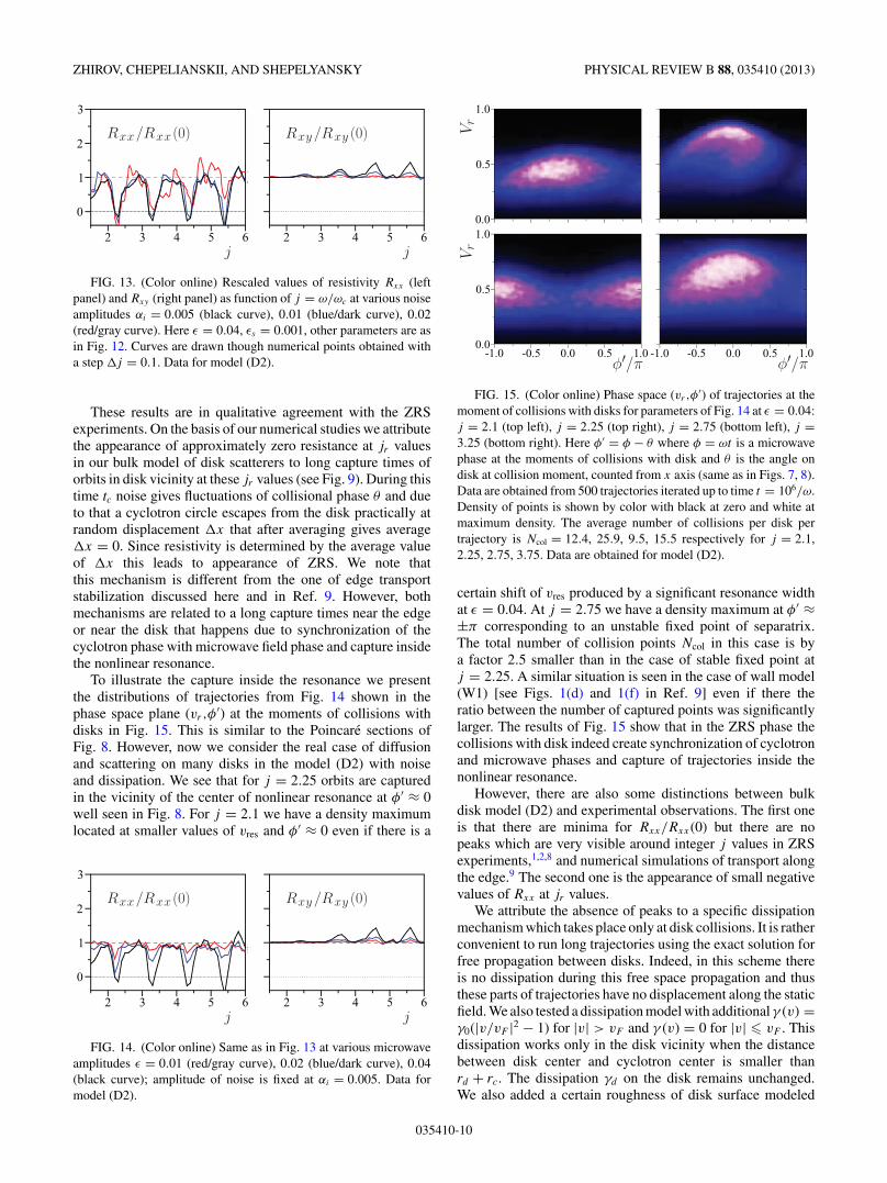
ZHIROV, CHEPELIANSKII, AND SHEPELYANSKY PHYSICAL REVIEW B 88, 035410 (2013)
0
1
2
3
2 3 4 5 6
...................
........................
........
.
......
.............
......................
........................
...........
.............
....................
.
......
..........
..............
.
.................................
.
......
.........
..................
.
..
..................
....................
......
.............
............
.
..............................
.........
.........
.................... .
..................
2 3 4 5 6
. . . . . . . . . . . . . . . . . . . . . . . . . . . . . . . . . . . . . . . . . .. . . .. . . . . . . . . . . . . . . . . . . . . . . . . . . . . . . . . . . . . . . . . . . . . .. . . . . . . . . . . . . . . . . . . . . . . . . . . . . . . .. . . . . . . . . .
.. . .
j
Rxx/Rxx (0)
j
Rxy /Rxy (0)
FIG. 13. (Color online) Rescaled values of resistivity Rxx (leftpanel) and Rxy (right panel) as function of j = ω/ωc at various noiseamplitudes αi = 0.005 (black curve), 0.01 (blue/dark curve), 0.02(red/gray curve). Here ε = 0.04, εs = 0.001, other parameters are asin Fig. 12. Curves are drawn though numerical points obtained witha step j = 0.1. Data for model (D2).
These results are in qualitative agreement with the ZRSexperiments. On the basis of our numerical studies we attributethe appearance of approximately zero resistance at jr valuesin our bulk model of disk scatterers to long capture times oforbits in disk vicinity at these jr values (see Fig. 9). During thistime tc noise gives fluctuations of collisional phase θ and dueto that a cyclotron circle escapes from the disk practically atrandom displacement x that after averaging gives average x = 0. Since resistivity is determined by the average valueof x this leads to appearance of ZRS. We note thatthis mechanism is different from the one of edge transportstabilization discussed here and in Ref. 9. However, bothmechanisms are related to a long capture times near the edgeor near the disk that happens due to synchronization of thecyclotron phase with microwave field phase and capture insidethe nonlinear resonance.
To illustrate the capture inside the resonance we presentthe distributions of trajectories from Fig. 14 shown in thephase space plane (vr,φ
′) at the moments of collisions withdisks in Fig. 15. This is similar to the Poincare sections ofFig. 8. However, now we consider the real case of diffusionand scattering on many disks in the model (D2) with noiseand dissipation. We see that for j = 2.25 orbits are capturedin the vicinity of the center of nonlinear resonance at φ′ ≈ 0well seen in Fig. 8. For j = 2.1 we have a density maximumlocated at smaller values of vres and φ′ ≈ 0 even if there is a
0
1
2
3
2 3 4 5 6
..............................
..............................................................
..................................
...................................
................................
.................................
......
.............
.....................................
....................
......
.............
............
.
..............................
.........
.........
.................... .
..................
2 3 4 5 6
. . . . . . . . . . . . . . . . . . . . . . . . . . . . . . . . . . . . . . . . . . . . . .. . . . . . . . . . . . . . . . . . . . . . . . . . . . . . . . . . . . . . . . . . . . . .. . . . . . . . . . . . . . . . . . . . . . . . . . . . . . . .. . . . . . . . . .
.. . .
j
Rxx/Rxx (0)
j
Rxy /Rxy (0)
FIG. 14. (Color online) Same as in Fig. 13 at various microwaveamplitudes ε = 0.01 (red/gray curve), 0.02 (blue/dark curve), 0.04(black curve); amplitude of noise is fixed at αi = 0.005. Data formodel (D2).
0.0
0.5
1.0
0.0
0.5
1.0
-1.0 -0.5 0.0 0.5 1.0 -1.0 -0.5 0.0 0.5 1.0
Vr
Vr
φ /π φ /π
FIG. 15. (Color online) Phase space (vr ,φ′) of trajectories at the
moment of collisions with disks for parameters of Fig. 14 at ε = 0.04:j = 2.1 (top left), j = 2.25 (top right), j = 2.75 (bottom left), j =3.25 (bottom right). Here φ′ = φ − θ where φ = ωt is a microwavephase at the moments of collisions with disk and θ is the angle ondisk at collision moment, counted from x axis (same as in Figs. 7, 8).Data are obtained from 500 trajectories iterated up to time t = 106/ω.Density of points is shown by color with black at zero and white atmaximum density. The average number of collisions per disk pertrajectory is Ncol = 12.4, 25.9, 9.5, 15.5 respectively for j = 2.1,2.25, 2.75, 3.75. Data are obtained for model (D2).
certain shift of vres produced by a significant resonance widthat ε = 0.04. At j = 2.75 we have a density maximum at φ′ ≈±π corresponding to an unstable fixed point of separatrix.The total number of collision points Ncol in this case is bya factor 2.5 smaller than in the case of stable fixed point atj = 2.25. A similar situation is seen in the case of wall model(W1) [see Figs. 1(d) and 1(f) in Ref. 9] even if there theratio between the number of captured points was significantlylarger. The results of Fig. 15 show that in the ZRS phase thecollisions with disk indeed create synchronization of cyclotronand microwave phases and capture of trajectories inside thenonlinear resonance.
However, there are also some distinctions between bulkdisk model (D2) and experimental observations. The first oneis that there are minima for Rxx/Rxx(0) but there are nopeaks which are very visible around integer j values in ZRSexperiments,1,2,8 and numerical simulations of transport alongthe edge.9 The second one is the appearance of small negativevalues of Rxx at jr values.
We attribute the absence of peaks to a specific dissipationmechanism which takes place only at disk collisions. It is ratherconvenient to run long trajectories using the exact solution forfree propagation between disks. Indeed, in this scheme thereis no dissipation during this free space propagation and thusthese parts of trajectories have no displacement along the staticfield. We also tested a dissipation model with additional γ (v) =γ0(|v/vF |2 − 1) for |v| > vF and γ (v) = 0 for |v| � vF . Thisdissipation works only in the disk vicinity when the distancebetween disk center and cyclotron center is smaller thanrd + rc. The dissipation γd on the disk remains unchanged.We also added a certain roughness of disk surface modeled
035410-10

TOWARDS A SYNCHRONIZATION THEORY OF . . . PHYSICAL REVIEW B 88, 035410 (2013)
-1
0
1
2
3
1.5 2.0 2.5 3.0 3.5 4.0
.............
.
..............
......................
.R
xx
/Rx
x(0
)
j
FIG. 16. Dependence of Rxx/Rxx(0) on j in the disk model withdissipation at disk collisions at rate γd = 0.01 and dissipation in diskvicinity with rate γ0/ω = 0.02; a disk roughness gives additionalangle rotations with amplitude αd = 0.1 (see text); the amplitude ofnoise in disk vicinity is αi = 0.001. Here we have ε = 0.04, εs =0.001; 51 numerical points in j are connected by lines to guide theeye. Data are obtained by averaging over 100 trajectories propagatingup to time t = 106/ω. Data for model (D3).
as an additional random angle rotation of velocity vector inthe range ±αd , done at the moment of collision with thedisk. We call this system disk model (D3). The results for theresistivity ratio Rxx/Rxx(0) are shown in Fig. 16. They showan appearance of clear peaks of Rxx/Rxx(0) in the presence ofsuch additional dissipation in the vicinity of integer j . Thereis also a small shift of minima from integer plus 1/4 to integerplus 0.4–0.5.
The second point of distinction from ZRS experimentsis a small negative value of Rxx at resonant j values. It isrelatively small for disk model (D2) (see Figs. 13, 14) and itbecomes more pronounced for disk model (D3) (see Fig. 16).It is possible that a scattering on the disk in the presence ofdissipation, noise, static, and microwave field gives a negativedisplacement x which generates such negative Rxx values.We expect that in the limit of static field going to zero thiseffect disappears. Indeed, the negative values become smallerat smaller εs according to the data of Fig. 11 but unfortu-nately the small εs limit is also very difficult to investigatenumerically.
We consider that at this stage of the theory the presenceof negatives values for Rxx does not constitute a criticaldisagreement. The escape parameters for electrons that havebeen captured on an impurity for a time long enough to makemany rotations around it are likely to strongly depend onthe model for the electron impurity interaction and furthertheoretical work on a more microscopic model is needed. Ingeneral a zero average displacement along the field directionseems natural for a smooth distribution of trapping timeswith a characteristic time scale much larger than the rotationtime around the impurity (this assumption does not seemto hold for our model; see for example the sharp featureson Fig. 10). Finally in Sec. VII we propose a slightlydifferent mechanism by which the combination of trapping onimpurities investigated here and electron-electron interactionscan lead to ZRS.
V. PHYSICAL SCALES OF ZRS EFFECT
The ZRS experiments1,2 show that the resistance Rxx
in the ZRS minima scales according to the Arrhenius lawRxx ∝ exp(−T0/T ) with a certain energy scale dependenton the strength of microwave field. In typical experimentalconditions one finds very large T0 ≈ 20 K at jr = 5/4 (see,e.g., Fig. 3 in Ref. 2). These data also indicate the dependenceT0 ∝ 1/jr ∝ B. This energy scale kBT0 is very large being onlyby a factor 7 smaller than the Fermi energy EF /kB ≈ 150 K.At the same time the amplitude of the microwave field is ratherweak corresponding to ε ≈ 0.003 at a field of 1 V/cm or tentimes larger at 10 V/cm (unfortunately it is not known what isthe amplitude of the microwave field acting on an electron).
As in Ref. 9 we argue that the Arrhenius scale is determinedby the energy resonance width (4) with T0 = Er/kB . Indeed,the resonance forms an energy barrier for a particle trappedinside the resonance by dissipative effects being analogousto a washboard potential. An escape from this potential wellrequires overcoming the energy Er leading to the Arrheniuslaw for Rxx dependence on temperature. Assuming the caseof the wall with ρ = 1 we obtain at E = 3 V/cm theactivation temperature T0 ≈ 23 K, in satisfactory agreementwith the experimental observations. The theoretical relation(4) also reproduces the experimental dependence T0 ∝ 1/jr
at ρ = 1. In this relation T0 ∝ ε ∝ E is confirmed by thenumerical simulations presented in Ref. 9. This dependence isin satisfactory agreement with the power dependence found inexperiments.1 In other samples one finds that the dependenceT0 ∝ ε2 works in a better way. We think that higher terms ina nonlinear resonance can be responsible for scaling T0 ∝ ε2
being different from the relation (4). Also a finite rigidity of thewall or disk scatterers can be responsible for the appearanceof the higher power of ε.
The energy scale Er on disks is enhanced by a factorρ = 1 + rc/rd for the case of radial field (4). However, weshowed that for a linear polarization the scale Er is given byEq. (5) and thus there is no enhancement at large ρ. Indeed,we performed direct simulations at parameters of Fig. 14 withthe reduced value of disk radius by a factor 2. The numericaldata give approximately the same traces Rxx/Rxx(0) vs j atε = 0.01,0.02,0.04 without visible signs of deeper minimaat small ε. This confirms the theoretical expressions (5).In any case, for small values rd � rc one should analyzethe quantum scattering problem which is significantly morecomplex compared to the classical case. We may assumethat in a quantum case one should replace rd by a magneticlength aB ≈ rc/
√ν ∝ √
B. In such a case we are getting ρ =1 + √
ν ≈ 9 that gives T0 ≈ 8 K at j ≈ 2.25 and microwaveamplitude E ≈ 3 V/cm. However, in this case we obtain thescale T0 being practically independent of j which differs fromexperimental data. In any case in experiments the size ofimpurities is small compared to rc and a quantum treatment isrequired to reproduce the correct picture for Rxx dependenceon parameters in the ZRS phase.
Another point is related to the positions of ZRS minimaon j axis. We recall that for the wall model the resonanceis located at vres = πδj/j (4) and that the separatrix width isδv = 4
√ε/j . The capture of trajectories from the bulk is most
efficient when a half width of separatrix touches the border
035410-11

ZHIROV, CHEPELIANSKII, AND SHEPELYANSKY PHYSICAL REVIEW B 88, 035410 (2013)
of bulk at vr = 0 with vres = δv/2 that gives the expressionδjε = 2
√εj/π for the wall case. At ε = 0.06, j = 2.25 this
gives δjε = 0.22 being in a good agreement with the numericaldata δj ≈ 1/4 for Rxx dependence on j (see Figs. 2, 3 in Ref. 9with a visible tendency of δj growth with j ). For the datapresented here in Fig. 14 for the disk case at ε = 0.04, ρ = 1 +j , j = 2.25 we obtain from (5) δjε = 0.11 that is slightly lessthan the numerical value δj ≈ 0.25 for minima location. Weattribute this difference to an approximate nature of expressionfor the resonance width at relatively strong microwave fields.We also note that in experiments an additional contribution tothe value of δj can appear due to a finite rigidity of disk andwall potentials.
VI. THEORETICAL PREDICTIONS FORZRS EXPERIMENTS
The theoretical models presented here and in Ref. 9 repro-duce the main experimental features of ZRS experiments.1,2,8
However, it would be useful to have some additional theoreticalpredictions which can be tested experimentally. A certaincharacteristic feature of both wall and disk models is theappearance of nonlinear resonance. For example, accordingto the wall model (W2) described by Eq. (3) the dynamicsinside the resonance is very similar to dynamics of a pendulum.The frequency of phase oscillations inside the resonance is�ph = √
K = 2√
εω/ωc = 2√
εj � 1.13 Here the frequencyis expressed in the number of map iterations and since thetime between collisions is approximately 2π/ωc we obtainthe physical frequency �r of these resonant oscillationsbeing �r/ω = �phωc/(2πω) = √
εωc/ω/π . At ε ∼ 0.02 thisfrequency is significantly smaller than the driving microwavefrequency. The dynamics inside the resonance should be verysensitive to perturbations at frequency ω1 ≈ �r that gives
ω1/ω =√
εωc/ω /π. (6)
To check this theoretical expectation we study numericallythe effect of additional microwave driving with dimensionalamplitude ε1 (ε1 � ε) and frequency ω1. We use the wallmodel (W2) based on the Chirikov standard map describedhere and in Ref. 9. As for the additional driving frequencywe have ε1 = |E1|/(ω1vF ) where E1 is the field strengthof microwave frequency ω1; we assume that both main andadditional fields are collinear and perpendicular to the wall.In the presence of the second frequency the map (3) takes theform
vy = vy + 2ε sin φ + 2ε1 sin(ω1φ/ω) + Icc,(7)
φ = φ + 2(π − vy)ω/ωc.
The only modification appears in the first equation since nowthe change of velocity at collision depends on both fields; thesecond equation remains the same as in (3). As in model (W2)the term Icc describes the effects of dissipation with rate γc andnoise with amplitude α of random velocity angle rotations. Wecall this system model (W3).
In model (W3) the resistance Rxx is computed numericallyin the same way as in model (W2) described in Ref. 9:The displacement along the edge between collisions is δx =2vy/ωc; it determines the total displacement x along the
edge during the total computation time t ∼ 104/ω; thenRxx ∝ 1/Dx = t/( x)2 where Dx is an effective diffusionrate along the edge. To see the effect of additional weaktest driving ε1 at frequency ω1 we place the system in theZRS phase at j = ω/ωc = 2.25 and measure the variation ofrescaled resistance Rxx/R
εxx(0). Here Rxx is the resistance
in the presence of both microwave fields ε and ε1 whileRε
xx(0) is the resistance at ε1 = 0 and a certain fixed ε. Thedependence of Rxx/R
εxx(0) on the frequency ratio is shown in
Fig. 17 in the left panel. The main feature of this data is theappearance of a peak at low frequency ratio ω1/ω < 0.1. Inthe range 0.1 < ω1/ω < 0.4 the testing field ε1 is nonresonantand does not affect Rxx ; however at ω1/ω < 0.1 it becomesresonant to the pendulum oscillations in the wall vicinity andhence strongly modifies the Rxx value. The dependence of thisresonance ratio ω1/ω on the amplitude of the main drivingfield ε is shown in the right panel of Fig. 17. The numericaldata are in a good agreement with the above theoreticalexpression (6).
The theoretical dependence (6) allows us to check thesynchronization theory of edge state stabilization. It alsoallows us to measure the strength of the main microwavedriving force acting on an electron that still remains anexperimental challenge. The experimental testing of relation(6) requires working with good ZRS samples which havevery low resistance in ZRS minima since this makes theeffect of testing field ω1 more visible. We note that therecent experiments in a low-frequency regime ω/ωc � 124
demonstrate that Rxx is sensitive to low-frequency driving.The expression (6) is written for the case when Rxx ismainly determined by transport along edges. If the dominantcontribution is given by bulk disk scatterers then a certainnumerical coefficient A should be introduced in the right partof the expression. According to the data of Fig. 8 and Eqs. (5)we estimate A ≈ 0.5 (the separatrix width is smaller for thedisk case compared to the wall case at the same ε).
Another interesting experimental possibility of our theoryverification is to take a Hall bar of a high-mobility 2DEGsample and put on it antidots with regular or disordereddistribution (it is important to have no direct collisionless pathfor a cyclotron radius in crossed dc electric and magneticfields) with a low density of antidot disks ndr
2d � 1 (as in
our numerical studies) so that an average distance betweenantidots is larger than the cyclotron radius rc. The regularantidot lattices have been already realized experimentally.18,19
The effect of microwave field on electron transport in a regularlattice has been studied in the frame of ratchet transportin asymmetric lattices.25 Even a case of symmetric circularantidots has been studied in Ref. 25 but the lattice was regularand no special attention was paid to analysis of resistivityat the ZRS resonant regime with j ≈ jr . The earlier studiesof the combined effect of microwave and magnetic fields on2DEG transport on a circular antidot lattice have been alsoreported in Ref. 26. However, in Ref. 26 the experiments weredone in the regime when the number of antidots Na inside thecyclotron circle area is larger than unity, while the conditionsof ZRS experiments correspond to Na � 1. We think that theexperimental conditions of Refs. 25,26 can be relatively easymodified to observe the ZRS effect on disk scatterers discussedhere.
035410-12
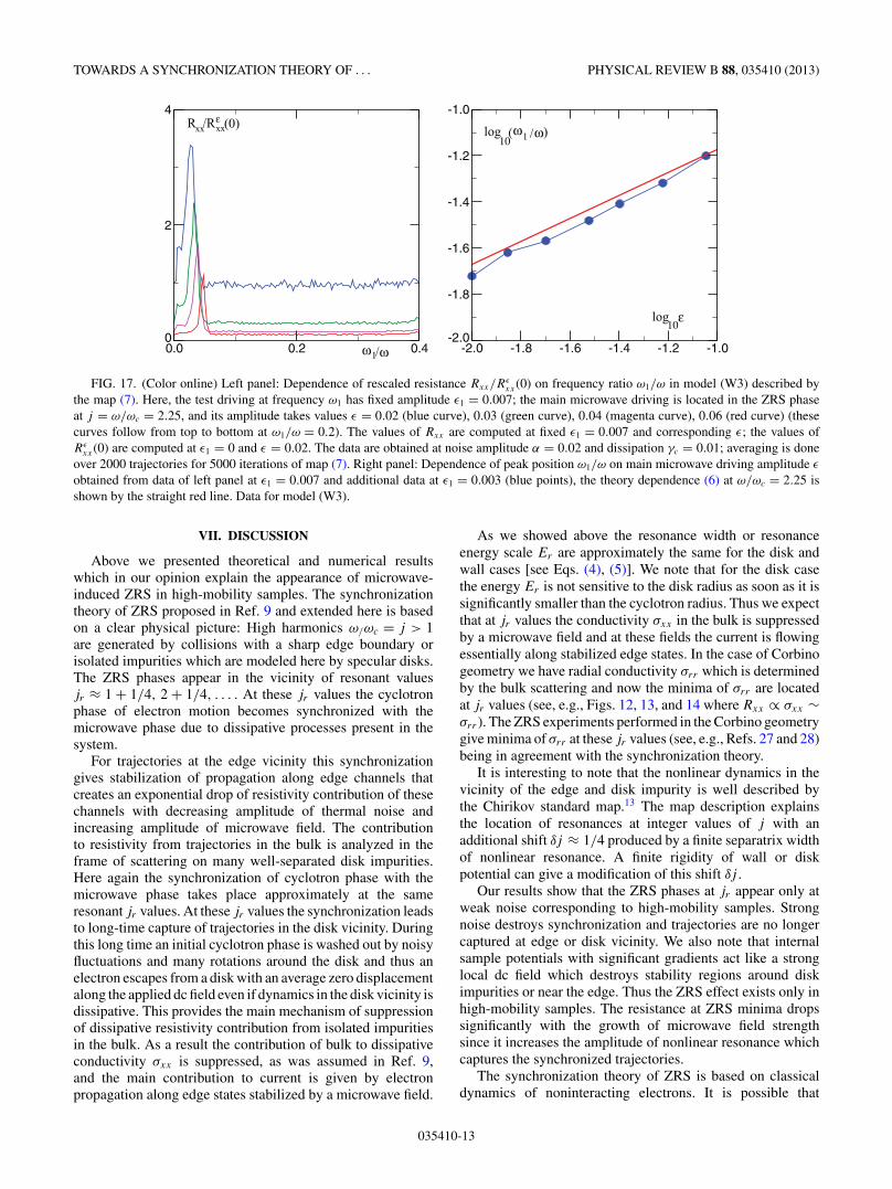
TOWARDS A SYNCHRONIZATION THEORY OF . . . PHYSICAL REVIEW B 88, 035410 (2013)
-2.0 -1.8 -1.6 -1.4 -1.2 -1.0-2.0
-1.8
-1.6
-1.4
-1.2
-1.0
log )ω ω
log
/1
ε
(10
10
0.0 0.2 0.40
2
4R /Rxx
ω ω
xx (0)
/1
ε
FIG. 17. (Color online) Left panel: Dependence of rescaled resistance Rxx/Rεxx(0) on frequency ratio ω1/ω in model (W3) described by
the map (7). Here, the test driving at frequency ω1 has fixed amplitude ε1 = 0.007; the main microwave driving is located in the ZRS phaseat j = ω/ωc = 2.25, and its amplitude takes values ε = 0.02 (blue curve), 0.03 (green curve), 0.04 (magenta curve), 0.06 (red curve) (thesecurves follow from top to bottom at ω1/ω = 0.2). The values of Rxx are computed at fixed ε1 = 0.007 and corresponding ε; the values ofRε
xx(0) are computed at ε1 = 0 and ε = 0.02. The data are obtained at noise amplitude α = 0.02 and dissipation γc = 0.01; averaging is doneover 2000 trajectories for 5000 iterations of map (7). Right panel: Dependence of peak position ω1/ω on main microwave driving amplitude ε
obtained from data of left panel at ε1 = 0.007 and additional data at ε1 = 0.003 (blue points), the theory dependence (6) at ω/ωc = 2.25 isshown by the straight red line. Data for model (W3).
VII. DISCUSSION
Above we presented theoretical and numerical resultswhich in our opinion explain the appearance of microwave-induced ZRS in high-mobility samples. The synchronizationtheory of ZRS proposed in Ref. 9 and extended here is basedon a clear physical picture: High harmonics ω/ωc = j > 1are generated by collisions with a sharp edge boundary orisolated impurities which are modeled here by specular disks.The ZRS phases appear in the vicinity of resonant valuesjr ≈ 1 + 1/4, 2 + 1/4, . . . . At these jr values the cyclotronphase of electron motion becomes synchronized with themicrowave phase due to dissipative processes present in thesystem.
For trajectories at the edge vicinity this synchronizationgives stabilization of propagation along edge channels thatcreates an exponential drop of resistivity contribution of thesechannels with decreasing amplitude of thermal noise andincreasing amplitude of microwave field. The contributionto resistivity from trajectories in the bulk is analyzed in theframe of scattering on many well-separated disk impurities.Here again the synchronization of cyclotron phase with themicrowave phase takes place approximately at the sameresonant jr values. At these jr values the synchronization leadsto long-time capture of trajectories in the disk vicinity. Duringthis long time an initial cyclotron phase is washed out by noisyfluctuations and many rotations around the disk and thus anelectron escapes from a disk with an average zero displacementalong the applied dc field even if dynamics in the disk vicinity isdissipative. This provides the main mechanism of suppressionof dissipative resistivity contribution from isolated impuritiesin the bulk. As a result the contribution of bulk to dissipativeconductivity σxx is suppressed, as was assumed in Ref. 9,and the main contribution to current is given by electronpropagation along edge states stabilized by a microwave field.
As we showed above the resonance width or resonanceenergy scale Er are approximately the same for the disk andwall cases [see Eqs. (4), (5)]. We note that for the disk casethe energy Er is not sensitive to the disk radius as soon as it issignificantly smaller than the cyclotron radius. Thus we expectthat at jr values the conductivity σxx in the bulk is suppressedby a microwave field and at these fields the current is flowingessentially along stabilized edge states. In the case of Corbinogeometry we have radial conductivity σrr which is determinedby the bulk scattering and now the minima of σrr are locatedat jr values (see, e.g., Figs. 12, 13, and 14 where Rxx ∝ σxx ∼σrr ). The ZRS experiments performed in the Corbino geometrygive minima of σrr at these jr values (see, e.g., Refs. 27 and 28)being in agreement with the synchronization theory.
It is interesting to note that the nonlinear dynamics in thevicinity of the edge and disk impurity is well described bythe Chirikov standard map.13 The map description explainsthe location of resonances at integer values of j with anadditional shift δj ≈ 1/4 produced by a finite separatrix widthof nonlinear resonance. A finite rigidity of wall or diskpotential can give a modification of this shift δj .
Our results show that the ZRS phases at jr appear only atweak noise corresponding to high-mobility samples. Strongnoise destroys synchronization and trajectories are no longercaptured at edge or disk vicinity. We also note that internalsample potentials with significant gradients act like a stronglocal dc field which destroys stability regions around diskimpurities or near the edge. Thus the ZRS effect exists only inhigh-mobility samples. The resistance at ZRS minima dropssignificantly with the growth of microwave field strengthsince it increases the amplitude of nonlinear resonance whichcaptures the synchronized trajectories.
The synchronization theory of ZRS is based on classicaldynamics of noninteracting electrons. It is possible that
035410-13

ZHIROV, CHEPELIANSKII, AND SHEPELYANSKY PHYSICAL REVIEW B 88, 035410 (2013)
electron-electron interaction effects can also suppress thecontribution to resistivity from neutral short-range scatterers(interface roughness, adatoms, etc.). Indeed, long capturetimes can increase the electron density around these short-ranged impurities transforming them into long-range chargedscatterers that the other electrons can circumvent by adia-batically following the long-range component of the disorderpotential thereby avoiding a scattering event. However, thetheoretical description of this short-ranged impurity cloakingmechanism for the ZRS effect remains a serious challenge.
Another important step remains the development of a quan-tum synchronization theory for ZRS. Even if in experimentsthe Landau level is relatively high ν ∼ 60, there are only aboutten Landau levels inside a nonlinear resonance9 and quantumeffects should play a significant role. The general theoreticalstudies show that the phenomenon of quantum synchronizationpersists at small effective values of Planck constant heff but itbecomes destroyed by quantum fluctuations at certain largevalues of heff .29
The importance of quantum ZRS theory is also relatedto the short-range nature of the impurities considered here,typically on a scale of a few nanometers or even less. Wehave modeled these impurities by disks with a radius that was
only several times (in fact j times) smaller than the cyclotronradius which is not so close to microscopic reality. We couldargue that in the quantum case a nanometer-sized impuritywould act effectively as an impurity of a size of quantummagnetic length aB ∼ rc/
√ν ≈ rc/8 ∼ 100 nm. This gives a
ratio rc/aB ∼ 8 which is comparable with the one used inour simulations with rc/rd = j ∼ 7 but of course a quantumtreatment of scattering on nanometer-size impurities in crossedelectric and magnetic and also microwave fields remains atheoretical challenge. We note that such type of scattering canbe efficiently analyzed by tools of quantum chaotic scattering(see, e.g., Refs. 30,31) and we expect that these tools will allowus to make progress in the quantum theory development ofstriking ZRS phenomenon. We hope that the synchronizationtheory of microwave-induced ZRS phenomenon describedhere can be tested in further ZRS experiments.
ACKNOWLEDGMENTS
This work was supported in part by ANR France PNANOproject NANOTERRA; O.V.Z. was partially supported bythe Ministry of Education and Science of the RussianFederation.
1R. G. Mani, J. H. Smet, K. von Klitzing, V. Narayanamurti, W. B.Johnson, and V. Umansky, Nature (London) 420, 646 (2002).
2M. A. Zudov, R. R. Du, L. N. Pfeiffer, and K. W. West, Phys. Rev.Lett. 90, 046807 (2003).
3S. I. Dorozhkin, JETP Lett. 77, 577 (2003).4J. H. Smet, B. Gorshunov, C. Jiang, L. Pfeiffer, K. West,V. Umansky, M. Dressel, R. Meisels, F. Kuchar, and K. von Klitzing,Phys. Rev. Lett. 95, 116804 (2005).
5A. A. Bykov, A. K. Bakarov, D. R. Islamov, and A. I. Toropov,JETP Lett. 84, 391 (2006).
6D. Konstantinov and K. Kono, Phys. Rev. Lett. 105, 226801(2010).
7D. Konstantinov, A. D. Chepelianskii, and K. Kono, J. Phys. Soc.Jpn. 81, 093601 (2012).
8I. A. Dmitriev, A. D. Mirlin, D. G. Polyakov, and M. A. Zudov,Rev. Mod. Phys. 84, 1709 (2012).
9A. D. Chepelianskii and D. L. Shepelyansky, Phys. Rev. B 80,241308(R) (2009).
10A. Pikovsky, M. Rosenblum, and J. Kurths, Synchronization:A Universal Concept in Nonlinear Sciences (Cambridge UniversityPress, Cambridge, 2001).
11A. D. Chepelianskii, arXiv:1110.2033.12W. G. Hoover, Time Reversibility, Computer Simulation, and Chaos
(World Scientific, Singapore, 1999).13B. V. Chirikov, Phys. Rep. 52, 263 (1979).14A. J. Lichtenberg and M. A. Lieberman, Regular and Chaotic
Dynamics (Springer, Berlin, 1992).15B. Chirikov and D. Shepelyansky, Scholarpedia 3(3), 3550 (2008).16Y. Avishai and G. Montambaux, Eur. Phys. J. B 79, 215 (2011).
17F. Benvenuto, G. Casati, I. Guarneri, and D. L. Shepelyansky,Z. Phys. B 84, 159 (1991).
18D. Weiss, M. L. Roukes, A. Menschig, P. Grambow, K. von Klitzing,and G. Weimann, Phys. Rev. Lett. 66, 2790 (1991).
19G. M. Gusev, V. T. Dolgopolov, Z. D. Kvon, A. A. Shashkin, V. M.Kudryashov, L. V. Litvin, and Yu. Nastaushev, Pis’ma Zh. Eksp.Teor. Fiz. 54, 369 (1991).
20R. Fleischmann, T. Geisel, and R. Ketzmerick, Phys. Rev. Lett. 68,1367 (1992).
21T. Geisel, R. Ketzmerick, and O. Schedletzky, Phys. Rev. Lett. 69,1680 (1992).
22N. Berglund, A. Hansen, E. H. Hauge, and J. Piasecki, Phys. Rev.Lett. 77, 2149 (1996).
23A. D. Chepelianskii and D. L. Shepelyansky, Phys. Rev. B 63,165310 (2001).
24A. D. Chepelianskii, J. Laidet, I. Farrer, H. E. Beere, D. A. Ritchie,and H. Bouchiat, Phys. Rev. B 86, 205108 (2012).
25S. Sassine, Yu. Krupko, J.-C. Portal, Z. D. Kvon, R. Murali, K. P.Martin, G. Hill, and A. D. Wieck, Phys. Rev. B 78, 045431 (2008).
26E. Vasiliadou, R. Fleischmann, D. Weiss, D. Heitmann, K. v.Klitzing, T. Geisel, R. Bergmann, and H. Schweizer, Phys. Rev.B 52, R8658 (1995).
27C. L. Yang, M. A. Zudov, T. A. Knuuttila, R. R. Du, L. N. Pfeiffer,and K. W. West, Phys. Rev. Lett. 91, 096803 (2003).
28A. A. Bykov, JETP Lett. 87, 551 (2008).29O. V. Zhirov and D. L. Shepelyansky, Eur. Phys. J. D 38, 375 (2006).30J. Wiersig and M. Hentschel, Phys. Rev. Lett. 100, 033901 (2008).31A. Eberspacher, J. Main, and G. Wunner, Phys. Rev. E 82, 046201
(2010).
035410-14
View publication statsView publication stats