towards a distributed modeling process based on … · 2014-03-25 · towards a distributed...
TRANSCRIPT

Towards a Distributed Modeling ProcessBased on Composite Models
Daniel Strüber, Gabriele Taentzer, Stefan Jurack, Tim Schäfer
Philipps-Universität Marburg, Germany,{strueber,taentzer,sjurack,timschaefer}@mathematik.uni-marburg.de
Abstract. The rising impact of software development in globally distributedteams strengthens the need for strategies that establish a clear separation of con-cerns in software models. Dealing with large, weakly modularized models andconflicting changes on interrelated models are typical obstacles to be witnessed.This paper proposes a structured process for distributed modeling based on themodularization technique provided by composite models with explicit interfaces.It provides a splitting activity for decomposing large models, discusses asyn-chronous and synchronous editing steps in relation to consistency managementand provides a merge activity allowing the reuse of code generators. All mainconcepts of composite modeling are precisely defined based on category theory.
Keywords: distributed modeling, composite models, model transformation, EMF
1 Introduction
Nowadays, model-driven development is a widely-spread paradigm to cope with thegrowing complexity of software requirements. Reliable technologies have emerged thatallow specifying an application on a high level of abstraction using models. These mod-els can then be transformed towards a running software system. Model-driven develop-ment is based on modeling languages that are usually defined using meta-modeling: ameta-model defines a language of individual models by predefining their structure. Animportant meta-modeling architecture has been proposed by the Object ManagementGroup in terms of the Meta Object Facility (MOF) [14]. An essential subset of MOFhas been implemented by the Eclipse Modeling Framework (EMF) [5].
When lifting concepts and tools from model-driven development to a distributedenvironment, a couple of challenges arise: contributors at different locations might beresponsible for models that are interconnected in some sense. Thus, clear conditionsand conventions for the editing of models are required to avoid the emergence of in-consistencies. Another drawback of existing tools is the sometimes monolithic natureof large models. Large models are difficult to comprehend and maintain. Thus, well-defined modularization strategies for models are required.
EMF models can be modularized using remote references between individual mod-els. The targets of remote references are then temporarily represented by proxy elementsand on demand replaced by the actual model element. In consequence, logically, all in-volved models constitute one big model. While this technique is sufficient for distribut-ing a large model over a set of resources, it does not establish well-known engineering

principles such as encapsulation and information hiding. Hence, we refer to this ap-proach as a physical modularization technique. In opposition, we propose compositemodels [8] as a logical modularization technique that establishes information hidingand allows for local consistency checks. A composite model comprises a set of com-ponents that are interconnected by export and import interfaces. Possible topologies ofmodel components are predefined by meta-model components. We provide core toolsupport for composite models and their transformation.
This paper utilizes composite models in order to address three questions that arisewhen lifting model-driven development to a distributed environment: (1) How can amodel be decomposed for logical modularization? (2) How can models be edited ina distributed way such that consistency between model components is preserved? (3)How can model-to-code transformation be performed when models are distributed?
Our solution to these questions is a process for distributed modeling. In order totackle question (1), a split activity is elaborated that decomposes a given model intoa set of components forming a composite model. As for question (2), we discuss howediting steps can be specified and performed in a systematic way using composite modeltransformation. As a tentative solution to question (3), a merge activity is introducedthat allows the reuse of existing code generation components.
The remainder of this paper is structured as follows: Sect. 2 provides the model-driven development of web applications as a running example. Composite models arerecapitulated in Sect. 3. An overview of the process forming the main contribution ofthis paper is given in Sect. 4. The activities constituting the process – split, edit, andmerge – are elaborated in Sects. 5, 6, and 7. We present an application scenario in Sect.8 and tool support in Sect. 9. Related work is discussed in Sect. 10. Sect. 11 concludes.
2 Scenario: Model-driven development of web applications
Web applications as a software domain have undergone domain analysis in visual webmodeling languages such as WebML [3] or UWE [11]. A common design decisionfound in these modeling languages is their branching into a set of viewpoint-orientedsub-languages – such as a structural data model, a presentation model and a navigationmodel. When a web application is to be developed by a distributed team, it is likely thatthe contributors obtain responsibilities for the different viewpoints, e.g. one contributoracts as domain modeler and another one as presentation modeler. Hence, we considerthis scenario as suitable for distributed modeling. To provide a full model-driven de-velopment infrastructure, domain-specific languages such as WebML and UWE aresupplemented with code generation facilities that define a language semantics.
As a running example, Fig. 1 provides the syntax for the Simple Web ApplicationLanguage (SWAL) as a modeling language for the specification of simple web appli-cations1. SWAL is specified by means of an EMF meta-model, comprising attributedmodel classes as nodes with directed references as edges. Classes may be abstract. Ref-erences may be containment references that ensure a tree-like structure for models.
1 The development of SWAL was initiated by Manuel Wimmer and Philip Langer at the Tech-nische Universität Wien and reimplemented for its use in modeling courses at the Philipps-Universität Marburg.
2

type
DataModel
Feature
ReferenceAttribute
HypertextModel
Page
StaticPageDynamicPage
IndexPage DetailsPage
Link
dataModel
entities
featurestype
startPage pageslinksentity
target
EntityDataTypedataTypes
Fig. 1: SWAL meta-model.
The class HypertextModel is used as root object of a web application to be spec-ified. It contains a hypertext structure of interconnected pages and a DataModel forthe specification of structural models of persistent data. Persistent data is based ondistinct Entities which are charaterized by a number of Features, i.e. Attributes andReferences. An attribute is typed over a primitive DataType, a reference over an entity.
Fig. 2: Poetry contest web applicationmodel.
The hypertext structure is based on Pagesbeing interconnected through Links. De-pending on its content, a page can eitherbe dynamic or static. A dynamic pagerefers to an entity and can either be anindex page displaying a list of availabledata records or a details page presentinga detailed view for a specific record.
Based on these concepts, in Fig. 2a poetry competition web application isspecified. Contest, poet, and poem enti-ties are to be displayed on interlinked in-dex and details pages. The concrete syn-tax given in the presentation facilitatesconvenient editing by hiding the Data-Model and HypertextModel classes: pages and entities are visualized as nodes in dif-ferent layouts. Hyperlinks, entity links, and references are visualized as arrows.
3 Composite Models
This paper investigates a process for distributed modeling based on composite models.Composite models provide a logical modularization technique for models by declaringexplicit export and import interfaces. Export and import interfaces identify model el-ements provided to and obtained from the environment, respectively. While an importis assigned to exactly one export, an export can serve an arbitrary number of imports.The core of a component is a conventional model called the body. Interfaces are char-acterized as sub-models of this body. While the model elements in export and import
3

B BE EIE
NetworkLevel
ObjectLevel
Fig. 3: Composite model with explicit export and import interfaces (taken from [7])
interfaces are identified with body elements, import interface elements are also identi-fied with export elements to establish interconnection. An interface can hide structuralcomplexity of its component body, e.g. by flattening its inheritance hierarchy. The in-terface structure of model components is predefined by meta-model components.
Consider Fig. 3 for a schematic representation of an example composite model withexplicit export and interfaces. The network level constitutes a topology of componentscomprising body, export, and import nodes and interconnecting edges. The object levelcomprises a set of interrelated models, each providing a refinement for one of the net-work nodes, with interrelating mappings. Dashed arrows indicate how interfaces areidentified with body models, dotted arrows indicate an assignment between an importand an export interface. Mappings on object level are compatible with network level ar-rows in the sense that source and target nodes of mapped arrows are mapped to sourceand target of the image arrow.
Formalization. The internal representation of models can be well represented by graphs.Therefore, the basis of our formalization are typed graphs and graph morphisms as de-fined in e.g., [4,9]. They form the category GRAPHSTG. Since the following definitionsof composite graphs and graph morphisms are given in a category-theoretical way, it isalso possible to use other kinds of graphs and morphisms as basic ingredients of com-posite graphs. For example, composite graphs over typed graphs with inheritance andcontainment are considered in [9].
Definition 1 (Composite network graph). A composite network graph is a graph Gtyped over graph CNG (shown on the right) by a graph morphism t : G → CNGsuch that the following constraints hold: (1) each export node is source of exactlyone network edge running to a body nodeand (2) each import node is source of ex-actly two network edges, one edge is run-ning to a body node and the other to anexport node. If there are export nodes with-out outgoing edges, corresponding compos-ite network graphs are called weak.
4

Definition 2 (Composite network graph morphism). Given two network graphs g :G → CNG and h : H → CNG, an injective graph morphism f : G → H forms avalid composite network graph morphism, short network morphism, if h ◦ f = g.
Composite network graphs and network graph morphisms form a category, calledCOMPONETGRAPHS, that is co-complete [9]. Weak composite network graphs andtheir morphisms also form a category, however, this one does not have pushouts.
Definition 3 (Composite Graph). Given a (weak) composite network graph G, a (weak)composite graph G over G is defined as G = (G,G(G),M(G)) with
– G(G) being a set of graphs, called local graphs, of category GRAPHS with eachgraph uniquely refining a network node in GN : G(G) = {G(n)| G(n) is a graphand n ∈ GN},
– for all paths G(x) ◦ G(y), G(z) : G(A) → G(B) we have G(x) ◦ G(y) = G(z).(commutative morphisms)
Definition 4 (Composite Graph Morphism). Given two (weak) composite graphs Gand H with composite network graphs G and H , resp., a (weak) composite (graph)morphism, written f : G→ H , is a pair f = (f,m) where
– f : G → H is a composite networkgraph morphism and
– m is a family of morphisms{f(n) | n ∈ GN} such that• for all nodes i ∈ GN :
f(i) : G(i) → H(fN (i)) is agraph morphism and
• for all edges e : i → j ∈ GE :H(fE(e))◦f(i) = f(j)◦G(e) (seethe illustration on the right).
i
e
��
G(i)f(i) //
G(e)
��
H(fN (i))
H(fE(e))
��j G(j)
f(j) // H(fN (j))
If morphism f and all morphisms in m are inclusions (injective), f is called inclusion(injective). Given a graph ˆTG and a composite morphism t : G→ ˆTG is called typedcomposite graph.
Composite graphs and graph morphisms form a category, called COMPGRAPHS,being co-complete. Weak composite graphs and weak composite morphisms form cate-gory COMPGRAPHSweak. COMPGRAPHSTG is the category of typed composite graphsand their morphisms. (See [9].)
This formalization induces that composite graphs are consistent in a certain sense:Since all morphisms have to be total, especially the ones between import and exportinterfaces, inconsistencies between components in the sense of unsatisfied imports maynot occur. It is up to future work to adapt composite models such that temporary incon-sistencies are tolerated, i.e., partial import mappings are allowed.
4 Distributed modeling process: overview
In this section, we give an overview on a modeling process that addresses three issuesto facilitate distributed model-driven development: (i) How can composite models be
5

used to structure models that lack an appropriate modularization? (ii) How can compos-ite models be edited systematically so that inconsistencies are avoided? (iii) How cancomposite models be used as a blueprint for code generation? We refer to this processas a distributed process in terms of a collection of activities that enable a distributedteam to work on a logically modularized model.
Fig. 4: Distributed modeling process.
Fig. 4 gives an outline of the process: When applying composite models to an exist-ing software development project, a monolithic model may exist that is required to bedecomposed. In order to support this, we propose a splitting technique. In the distributedmodeling phase following up, editing steps are performed, involving asynchronous orsynchronous editing as well as changes of the network structure. Afterwards, in orderto support code generation, all components may be merged together. The resulting codemay have gaps to be filled in by the distributed team.
Please note that this overview refers to models on an arbitrary meta-level, e.g. mod-els in application development or language development. However, the full potentialof the process becomes evident when it is applied on two interrelated levels, e.g., ap-plication and language development. For instance, a legacy meta-model may be splitby language developers. Conforming application models are then split according to thelanguage decomposition by application developers. This notion is elaborated further inthe following sections presenting the outlined modeling activities.
5 Model splitting
This section elaborates on model splitting as a migration technique for introducing thelogical modularization technique provided by composite models to existing softwaredevelopment projects. It assumes a monolithic model or a set of models interconnectedby remote references and produces a composite model comprising a set of model com-ponents interconnected by export and import interfaces. Meta-models as well as their
6
DataModel
Feature
ReferenceAttribute
dataTypes
features type
EntityHypertextModel
Page
StaticPageDynamicPage
IndexPage DetailsPage
Link
startPage
pageslinks
entity target
entities
SwalData SwalHypertext
DataTypeentities
type
Entity
DataModeldataModelImp
Exp
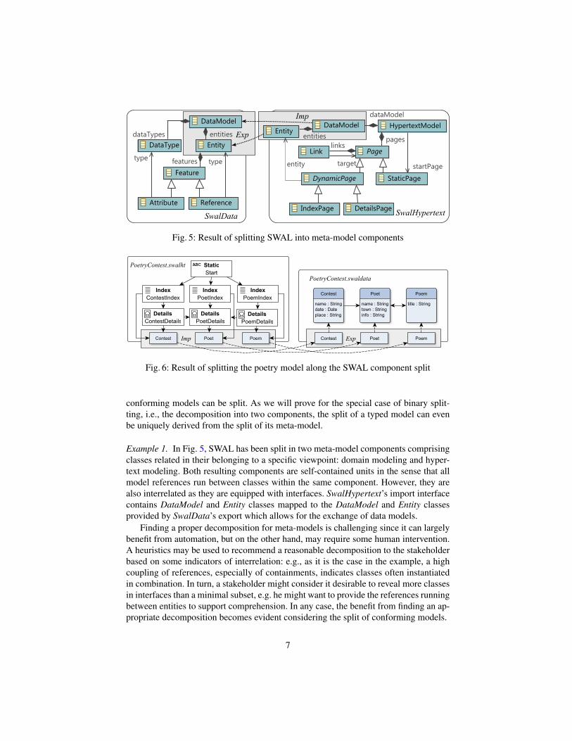
Fig. 5: Result of splitting SWAL into meta-model components
Fig. 6: Result of splitting the poetry model along the SWAL component split
conforming models can be split. As we will prove for the special case of binary split-ting, i.e., the decomposition into two components, the split of a typed model can evenbe uniquely derived from the split of its meta-model.
Example 1. In Fig. 5, SWAL has been split in two meta-model components comprisingclasses related in their belonging to a specific viewpoint: domain modeling and hyper-text modeling. Both resulting components are self-contained units in the sense that allmodel references run between classes within the same component. However, they arealso interrelated as they are equipped with interfaces. SwalHypertext’s import interfacecontains DataModel and Entity classes mapped to the DataModel and Entity classesprovided by SwalData’s export which allows for the exchange of data models.
Finding a proper decomposition for meta-models is challenging since it can largelybenefit from automation, but on the other hand, may require some human intervention.A heuristics may be used to recommend a reasonable decomposition to the stakeholderbased on some indicators of interrelation: e.g., as it is the case in the example, a highcoupling of references, especially of containments, indicates classes often instantiatedin combination. In turn, a stakeholder might consider it desirable to reveal more classesin interfaces than a minimal subset, e.g. he might want to provide the references runningbetween entities to support comprehension. In any case, the benefit from finding an ap-propriate decomposition becomes evident considering the split of conforming models.
7

In Fig. 6, the poetry contest model is split towards the viewpoint meta-models in-troduced in Fig. 5. For better readability, exported model elements are shown separatedfrom their body elements. Both meta-model components are instantiated by conformingmodel components. Especially, export and import interfaces are instantiated and usedfor the sharing of entities between both components. As the split follows the typing ofmodel elements and their assignment to meta-model components, it can be automatized.
Formalization. In the following, a formalization is provided for splitting a meta-modelin two meta-model components with intermediate export and import interfaces and,furthermore, for splitting conforming models along that split. Any meta-model that canbe represented as a plain graph can be used as input, e.g., a single self-contained modelor a group of models interconnected by remote references.
Proposition 1 (Binary split of a composite graph). Given graph G and two sub-graphs G1 and G2 with inclusions g1 : G1 → G and g2 : G2 → G, their intercon-necting interfaces can be uniquely determined such that the resulting diagram forms avalid composite graph with two components.
Proof. Let square (1) in the figure below be a pullback and (2) an epi-mono-factoriza-tion. Then, graph GI and morphisms i1 and i2 are uniquely determined, up to isomor-phism. The epi-mono-factorization splits morphism i2 into a surjective and an injectivepart. Graph GE and morphisms e2 and ie are uniquely determined by this factorization.Diagram i1, ie, and e2 forms a valid composite graph with two components. Its networkgraph is well typed over the component network graph defined in Def. 1.
Proposition 2 (Binary split of a typed composite graph). Given a type graph TGwith its subgraphs TG1 and TG2 and a binary split as in the upper part of the figurebelow. Moreover, graph G with its typing t over TG is given. There is a unique bi-nary split of G being type compatible with the resulting composite type graph. I.e. allmorphisms in the diagram below exist and form a commuting diagram. The result is acomposite graph typed over the split of TG.
Proof. The following steps can be performed:1. (t1, g1) is constructed as pullback over
(t, tg1).2. (t2, g2) is constructed as pullback over
(t, tg2).3. (ti, i1) is constructed as pullback over
(ti1, t1).4. Morphism i2 is the induced morphism by
pullback (t2, g2) and morphisms g1◦ i1 andti2◦ti such that t2◦i2 = ti2◦ti and g1◦i1 =g2 ◦ i2.
5. (e2, te) is constructed as pullback over(t2, te2).
6. Morphism ie is the induced morphism bythe pullback (e2, te) and morphisms i2 andti ◦ tie such that i2 = e2 ◦ ie and tie ◦ ti =te ◦ ie.
TG1oo ti1
OO
t1
TGI
tie
��
OO
ti
TG��
tg1
ootg2OO
t
TG2
��
ti2
OO
t2
TGEte2oo
OO
teG1oo i1
GI
ie
��
(1) (2)
G��
g1
oog2
G2
��
i2
GEe2oo
8

Considering the view-oriented splitting of large meta-models as e.g. for UML, itmakes sense to iterate several binary splits. An example split scenario for UML canlook like this: (1) split the structure component from the behavioral component, (2)split the structure component further into package and class structure components, (3)split the behavioral component into a basic action component and a behavior diagramscomponent, and (4) continue splitting this component until the well-known behaviordiagrams are each separated in model components. Of course, component interfaceshave to be continuously adapted during this splitting process.
6 Distributed model editing
A crucial challenge of collaborative editing is to preserve the consistency of modelswhile keeping editing steps as independent as possible. Several approaches to the han-dling of model inconsistency, being defined as the maintenance of contradictory infor-mation within a network of models, center on the detection and resolution of incon-sistencies [13] [6]. These approaches rely on facilities to perform a global consistencycheck on the distributed model which, though, might not always be available, e.g., forsecurity reasons or due to network failures. Hence, we propose a complementary strat-egy of inconsistency avoidance, giving editing steps at hand that are classified as ei-ther safe or critical to the consistency of models. We provide the notion of a relaxedconsistency avoidance that allows performing critical steps if necessary. In contrast, astrict inconsistency avoidance may be an obstacle to the natural evolution of a softwareproject and is prone to dead-lock situations.
Existing collaborative model editors such as Papyrus [15] or MagicDraw [12] im-plement a strategy for inconsistency avoidance by locking selected model parts for mod-ification. These editors follow an asynchronous approach to editing single models thatcan be displayed and modified in multiple distributed editors at once. As for the use ofcomposite models, the management of consistency is facilitated by the maintenance ofinterfaces. It is desirable to support asynchronous and synchronous editing steps: for in-stance, two related components with related contents might be expanded by individualcontributors or in parallel by one contributor. Thus, this section discusses asynchronousas well as synchronous editing steps and their formalization based on the transformationof composite graphs. Using our basic implementation of composite model transforma-tion comprising a rule editor and interpreter engine tool suite, it is possible to deploytransformation rules as editing steps, e.g. refactorings, within an existing editor such asPapyrus.
Example 2. For the poetry contest application specified in the Fig. 6, new requirementsmight be stated, e.g., the management of books. When domain and hypertext compo-nents are developed independently, the first action done is that the domain modeler addsthis new entity to the body and export of the swaldata component. The hypertext mod-eler then adds the entity to the import interface and body of the swalht component andcreates corresponding pages for the entity resulting in the model shown in Fig. 7. Incontrast, it might also be desirable to perform these changes in parallel: e.g., imaginean editing command that adds an entity and corresponding pages to both components.We distinguish these two kinds of editing as asynchronous and synchronous editing.
9
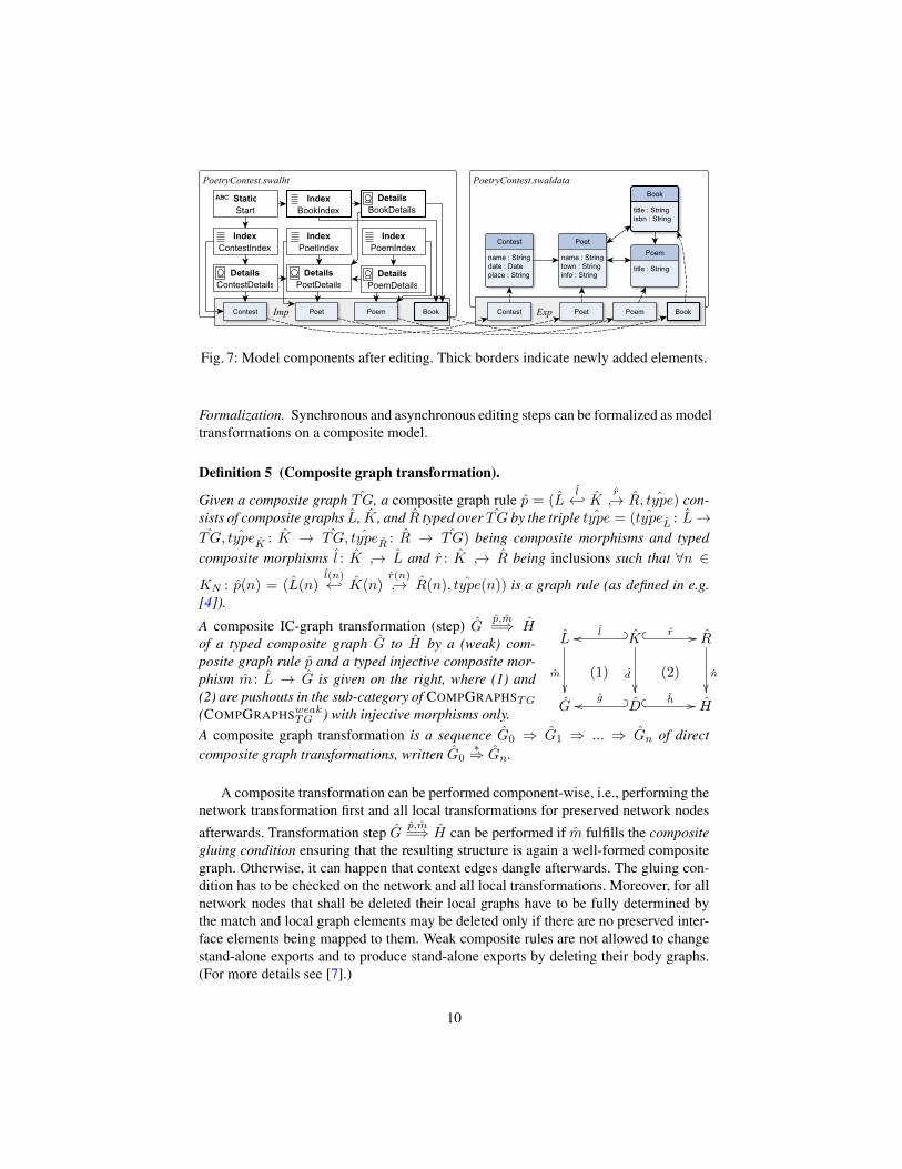
Fig. 7: Model components after editing. Thick borders indicate newly added elements.
Formalization. Synchronous and asynchronous editing steps can be formalized as modeltransformations on a composite model.
Definition 5 (Composite graph transformation).
Given a composite graph ˆTG, a composite graph rule p = (Ll←↩ K r
↪→ R, ˆtype) con-sists of composite graphs L, K, and R typed over ˆTG by the triple ˆtype = ( ˆtypeL : L→ˆTG, ˆtypeK : K → ˆTG, ˆtypeR : R → ˆTG) being composite morphisms and typed
composite morphisms l : K ↪→ L and r : K ↪→ R being inclusions such that ∀n ∈
KN : p(n) = (L(n)l(n)←↩ K(n)
r(n)↪→ R(n), ˆtype(n)) is a graph rule (as defined in e.g.
[4]).
A composite IC-graph transformation (step) Gp,m=⇒ H
of a typed composite graph G to H by a (weak) com-posite graph rule p and a typed injective composite mor-phism m : L → G is given on the right, where (1) and(2) are pushouts in the sub-category of COMPGRAPHSTG
(COMPGRAPHSweakTG ) with injective morphisms only.
L
m
��
K? _loo
d
��
� � r // R
n
��(1) (2)
G D? _goo � � h // H
A composite graph transformation is a sequence G0 ⇒ G1 ⇒ ... ⇒ Gn of directcomposite graph transformations, written G0
∗⇒ Gn.
A composite transformation can be performed component-wise, i.e., performing thenetwork transformation first and all local transformations for preserved network nodes
afterwards. Transformation step Gp,m=⇒ H can be performed if m fulfills the composite
gluing condition ensuring that the resulting structure is again a well-formed compositegraph. Otherwise, it can happen that context edges dangle afterwards. The gluing con-dition has to be checked on the network and all local transformations. Moreover, for allnetwork nodes that shall be deleted their local graphs have to be fully determined bythe match and local graph elements may be deleted only if there are no preserved inter-face elements being mapped to them. Weak composite rules are not allowed to changestand-alone exports and to produce stand-alone exports by deleting their body graphs.(For more details see [7].)
10

Fig. 8: Synchronous and asynchronous composite model transformation rules.
Example 3. Two sample composite rules, shown in a compact representation, are pro-vided in Fig. 8. «Del» and «New» keywords denote nodes as being contained in L− Kor R − K, respectively. Rule a) is a synchronous rule specifying the addition of a newentity and corresponding index and details pages to both components in parallel. Ruleb) is an asynchronous rule removing an entity from a body and an adjacent export. Ap-plying rule a) to the composite model in Fig. 6 yields a composite graph. Since nothingis deleted, the composite gluing condition is obviously fulfilled. To obtain the com-posite model in Fig. 7, additional references between book, poem, and poet have to beadded by another editing step. Wrt. global consistency, rule a) is evidently neutral asan intact export/import relation is introduced. The editing step specified by rule b) is tobe considered a critical one since the export interface being edited might be referred tofrom a remote import interface. Hence, a user performing an editing step like this maybe warned and suggested to clarify the editing step to his collaborators.
7 Model merging for code generation
Fig. 9: Merged application model.
Aiming at providing a full life-cycle of model-driven development, code generation as a seman-tics for composite models is to be investigated.Generally speaking, two different strategies areconceivable: A distributed code generation allow-ing the successive code generation for individualcomponents is an interesting idea deserving fur-ther research. However, in this section, we focuson the second strategy: Existing code generatorscan be reused to perform a centralized code gen-eration. As input for the generator, a single modelconforming to the original language before thelanguage split is required. We provide a techniqueto support the merging of a composite model to a single model serving as a blueprintfor code generation.
11

Example 4. Fig. 9 shows how the composite model provided in Fig. 7 is merged. Themerge exploits the information available in import and export interfaces: Pairs of objectsare identified as corresponding and can thus be merged. The result of the merge is well-typed because it conforms to the original pre-split meta-model. A merge of meta-modelscan be performed applying the same strategy.
Formalization. We provide a formalization for the merge of a composite model.
Proposition 3 (Graph merge). Given a composite graph, there is a unique graph con-taining its merge result.
Proof. Considering a composite graph C as a diagram in category GRAPHSTG, its col-imit consists of a simple graph G and a family of graph mophisms from all local graphsof C to G. The colimes construction is uniquely determined.
8 Application scenario
This section provides a simple application scenario to show how the distributed processis applied. The scenario, illustrated in Fig. 10, concerns with web application develop-ment based on the SWAL web modeling language. We assume that the language alreadyhas been subject to a split into domain and hypertext components that was performedby the language developers.
Fig. 10: Scenario for distributed editing process
The starting point is a monolithic model M conforming to SWAL. M is logicallydistributed when project manager Samantha performs a split along the given language-level decomposition. The resulting composite model comprises domain model compo-nent D and hypertext model component H being interconnected by means of export andimport interfaces. Samantha now assigns team members to viewpoints: Frank receives
12

responsibility for domain modeling, Mike becomes the hypertext modeler. The internaldetails of remote components are hidden to both developers respectively: Frank’s scopeof visibility is restricted to his assigned component, D. Mike’s scope of visibility com-prises his assigned component, H, and remote component D’s export (cf. the concept ofweak composite graphs introduced in Sect. 3). From now on, Frank and Mike performasynchronous editing steps, reflected in increasing version numbers. The first steps per-formed are neutral to inter-model consistency and do not require conflict handling.
Eventually, the transformation from D2 to D3 is a critical editing step threateningglobal consistency, e.g. the deletion of a model element being visible in the export.Hence, when performing this editing step, Frank receives a warning. His options are: tomanually establish communication to Mike clarifying the change, to let a default mes-sage be delivered to Mike, to take back the change or to do nothing. In the two formercases, Mike can react by performing an editing step such that consistency is retained.When doing nothing, consistence might be broken. Later on, Samantha performs a syn-chronous editing step changing both components in parallel. Eventually, she decidesthat the model components have accomplished a solid state and should be merged forcode generation. A global consistency check may be performed before the merge toensure a valid result. If at some later point in time new requirements are added, furtherediting can be performed on the components in their state before the merge.
To summarize, the maintenance of explicit export and import interfaces allows toreason about a smart and relaxed conflict avoidance: at all times, developers are awarewhether their editing is either safe or critical to inter-model consistency. In the caseof critical steps, further intervention may become necessary. However, an automatizedconflict detection and resolution algorithm can be considered complementary and mightbe applied at any time throughout the development process. Especially a conflict detec-tion step right before the code generation step is highly desirable.
9 Tool support
The core processing of composite models is supported by an existing editor environ-ment based on the Eclipse Modeling Framework. For a set of individual models, wiz-ard tools are provided allowing the derivation of export and import interfaces in orderto establish model interconnection. Export and import interfaces are implemented asseparate resources with special references, supported by a delegation mechanism thatreplaces EMF’s proxy concept. Furthermore, we have implemented a model transfor-mation language and tool set allowing the specification and execution of editing stepsthat can be integrated in an existing editor. The tool set is open source being provided athttp://www.uni-marburg.de/fb12/swt/forschung/software along with ex-amples and a tutorial. The automation of splitting and merging is left to future work.
10 Related Work
In this section, we compare our work to several other approaches for dealing with largeand distributed models.
13

10.1 Model slicing
The extraction of sub-models from large models has been considered under the headingof model slicing. [2] presents a tool that allows defining model slicers for domain-specific languages by determining a selection of classes and features to extract. [10]provides an elegant formalization of model slicing as they prove that the sub-modelsgained from slicing along particular references constitute a lattice. A linear-time al-gorithm establishing this decomposition is elaborated. These approaches differ frommodel splitting in so far as they aim at extracting sub-models conforming to the samemeta-model as the model to be sliced. In turn, model splitting is integrated into an over-lying process: a meta-model is split in several components. Afterwards, models basedon these meta-models are split towards these components. The splitting of a model to-wards components with export and import interfaces is specific to our approach.
10.2 Consistency management in distributed modeling
As discussed before, we propose a relaxed inconsistency avoidance as a supplementarystrategy to inconsistency detection and resolution. An elaborated strategy for the lat-ter is given by Macromodeling [16]. Macromodeling allows integrating multiple mod-els of different modeling languages on type and instance layers. A major objective ofmacromodeling is the check of global consistency conditions based on logical formu-las. However, it does neither envision a specific modeling process nor the use of explicitinterfaces.
10.3 Model weaving
The merge of models can be compared to the weaving of models that is implementedby different tools, e.g., Atlas Model Weaver (AMW) [1]. AMW allows the weaving aset of models by constructing a weave model based on a weave meta-model. It supportsthe manual and semi-automatic weaving of models by means of heuristic-based trans-formations. Our merging, in turn, is restricted to composite models as input models. Itcan be fully automatized exploiting the information given by import/export relations.
11 Conclusion and Outlook
The global distribution of software development spawns a need for new well-definedsoftware engineering methods. The process presented in this paper is our contributionto satisfying this need. It proposes split, edit and merge activities based on compositemodels which have been introduced as a formally sound modularization mechanism,allowing for local consistency checks and systematic transformation.
Future work is the enhancement of existing tool support towards a comprehensivetool environment supporting all parts of the presented distributed modeling process.Firstly, we aim at providing convenient editor support that allows editing componentsequipped with interfaces at the right level at abstraction. Secondly, splitting and mergingare to be automatized. It is of our particular interest to find a heuristics that gives rea-sonable suggestions for splitting. Thirdly, in addition to the centralized code generation
14

approach introduced here, a distributed code generation facility shall be implemented.In particular, it is to investigate how import/export relations are dealt with when gen-erating code for individual components. Having a suitable tool support at hand, we areheading towards larger examples that show the scalability of this approach. We are con-vinced that precisely defined basic operations on composite models are a clear basis fora sound distributed modeling process.
References1. AMW: Atlas Model Weaver. http://www.eclipse.org/gmt/amw2. Blouin, A., Combemale, B., Baudry, B., Beaudoux, O.: Modeling model slicers. In: Proceed-
ings of the International Conference on Model Driven Engineering Languages and Systems(MODELS). pp. 62 – 76. Wellington, New Zealand (Oct 2011), http://hal.inria.fr/inria-00609072/PDF/BLO11b.pdf
3. Ceri, S., Fraternali, P., Bongio, A.: Web Modeling Language (WebML): a modeling languagefor designing Web sites. Computer Networks 33(1-6), 137 – 157 (2000), http://www.sciencedirect.com/science/article/pii/S1389128600000402
4. Ehrig, H., Ehrig, K., Prange, U., Taentzer, G.: Fundamentals of Algebraic Graph Transfor-mation. Monographs in Theoretical Computer Science. An EATCS Series, Springer (2006)
5. EMF: Eclipse Modeling Framework. http://www.eclipse.org/emf (2011)6. Goedicke, M., Meyer, T., Taentzer, G.: ViewPoint-oriented Software Development by Dis-
tributed Graph Transformation: Towards a Basis for Living with Inconsistencies. In: Proc.4th IEEE Int. Symposium on Requirements Engineering (RE’99), June 7-11, 1999, Univer-sity of Limerick, Ireland. IEEE Computer Society (1999), iSBN 0-7695-0188-5
7. Jurack, S.: Composite Modeling based on Distributed Graph Transformation and the EclipseModeling Framework. dissertation, Philipps-Universität Marburg (2012)
8. Jurack, S., Taentzer, G.: Towards Composite Model Transformations Using DistributedGraph Transformation Concepts. In: Schürr, A., Selic, B. (eds.) Proc. of 12th Int. Confer-ence on Model Driven Engineering Languages and Systems (MoDELS 2009). LNCS, vol.5795, pp. 226–240. Springer (2009)
9. Jurack, S., Taentzer, G.: Transformation of Typed Composite Graphs with Inheritance andContainment Structures. Fundamenta Informaticae 118(1-2), 97–134 (2012)
10. Kelsen, P., Ma, Q.: A Modular Model Composition Technique. In: Rosenblum, D.S.,Taentzer, G. (eds.) 13. International Conference on Fundamental Approaches to SoftwareEngineering, FASE 2010, Held as Part of the Joint European Conferences on Theory andPractice of Software, ETAPS 2010, Paphos, Cyprus. LNCS, vol. 6013, pp. 173–187. Springer(2010)
11. Kraus, A., Knapp, A., Koch, N.: Model-Driven Generation of Web Applications in UWE. In:Proceedings of the 3rd International Workshop on Model-Driven Web Engineering MDWE2007, Como, Italy, July 17, 2007 (2007)
12. Magic Draw: http://www.magicdraw.com13. Mougenot, A., Blanc, X., Gervais, M.P.: D-Praxis: A Peer-to-Peer Collaborative Model Edit-
ing Framework. In: 9th IFIP international conference on Distributed Applications and Inter-operable Systems (DAIS’09). pp. 16–29. Lisbonne, Portugal (Jun 2009)
14. OMG: The Essential MOF (EMOF) Model. http://www.omg.org/cgi-bin/doc?formal/2006-01-01.pdf (2010), sec. 12
15. Papyrus UML: http://www.papyrusuml.org16. Salay, R., Mylopoulos, J., Easterbrook, S.M.: Managing models through macromodeling. In:
23rd IEEE/ACM International Conference on Automated Software Engineering (ASE 2008),15-19 September 2008, L’Aquila, Italy. pp. 447–450. IEEE (2008)
15