towards a decision-support framework for embodiment phase
TRANSCRIPT

Ar~ifcial Intelligence in Engineering 7 (1992) 21-36
Towards a decision-support framework for the embodiment phase of mechanical design
Amaresh Chakrabarti, Thomas P. Bligh & Tony Holden Engineering Design Centre, Department of Engineering, University o$ Cambridge, UK
(Received 3 October 1990; revised version received 3 June 199 I ; accepted I 3 August 199 1)
The main activities involved in mechanical embodiment design are understood as those of identvying the important physical and functional constraims from the knowledge of the solution, derived during the conceptual design phase, and that of the physical situation in which it has to work; and, propagaring the above consrrainrs by a design strategy to obtain the physical description. It is argued that these constraints are the ones that form the basis for the subsequent design. This paper addresses the problems associated with idenrification ofconstraints, proposes a solution framework based on the use of behaviour as the linking element between function and structure, and discusses the suitability of a hierarchical object-oriented knowledge representation scheme for supporting its implementation.
Key words: engineering design, computer aided design, mechanical design, embodiment design, knowledge based system, qualitative physics, constraint identification, decision-support system, function-structure- behaviour representation.
1 INTRODUCTION
Engineering design consists of transforming a set of requirements into a set of physical descriptions that are able to fulfil those specified requirements. According to one school of thought,” design can be systematized into four general phases: clarification of task, conceptual design, embodiment design, and detail design.
The above general design process is, more or less, commonly applicable to any domain of knowledge, but especially that in mechanical engineering design.
The use of computers in design is constrained mainly by two factors, usability and usefulness.
The usability of computers in any domain of know- ledge depends on how organized that domain is. In the context of mechanical design, the available degree of organization increases as we proceed down the design phases. The conceptual design, therefore, is the least organized, on through to the detail design which is highly organized.
The usefulness is the advantage of using computers over conventional methods. Computers already are estab- lished as useful for high-speed calculation-intensive tasks and are thus well-suited for the detail design phase.
Artificial Intelligence in Engineering 0954-1810/92/$05.00 0 1992 Elsevier Science Publishers Ltd.
21
FEM, CAD and, solid and surface modellers, along with computer-aided manufacturing packages were developed and are now being used increasingly for modelling and manufacturing complicated shapes. Within the confines of vertically-integrated programs, some optimization programs were developed. Thus, computers are already well integrated into the detail design and manufacturing phases.
The remaining problem, however, is the extent to which computers could be used and useful in the earlier, looser, and more creative phases of design.
Observation indicates that human designers are good at the creative aspects of design and at the intricate details of each small part of a large design task. Problems arise over the overall integration and consistency of a large design project. An added complication is that teams of specialist-designers are often employed to deal with parts of a large design task. This brings, along with all its advantages, considerable difficulties of communication and integration. Normally, designers proceed by making many assumptions during the early phases. These are permeated into the design, and are often accepted by sub-teams who are not necessarily in a position to judge their accuracy or validity, or indeed they may not realize that these are no more than best guesses and consequently the basis of each decision may be lost. In complex designs, the task of keeping track of all aspects, which are

22 A. Chakrabarti, T.P. Bligh, T. Holden
influenced by each assumption, is a formidable one. When the assumptions are improved or changed by more detailed and better knowledge, every part of the design which is influenced should, in an intelligent way, be changed. If we had a computer-based framework for design, these problems could be dealt with.
Now, what is a reasonable area of non-trivial intel- ligent activity in design in which the suitability of computers could be explored? In our view, one possibility is the area of embodiment design. Conceptual design being more imprecise, unorganized and creative, is left for a later paper.
There are essentially three main tasks which need to be done in order that computers can do at least some part of the non-creative intelligent activities encountered during embodiment design. Firstly, we have the task of structuring the embodiment design process to elucidate the non-creative intelligent activities suitable for computers. Secondly, there is the task of developing a general framework in which to continue an interactive decision-making activity. And thirdly, we are left with the task of providing a formalism which will have the necessary constructs for representing, modifying and evolving the design solutions.
In the first section of this paper, a systematic approach to design is outlined with reference to a specific example. The second section investigates the problem of using computers in embodiment design and, a solution frame- work is proposed in the third section. In Section 4, the pieces of knowledge required to support the solution framework are identified, and a possible knowledge-base is discussed.
2 A SYSTEMATIC DESIGN PROCESS
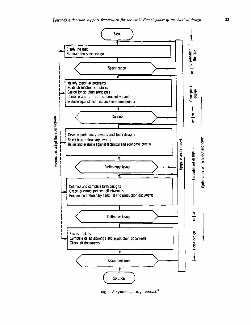
Figure 1 shows the main phases of a systematic design process. lo Briefly these can be described as:
Clarification of task: This involves the collection and interpretation of information about the requirements to be embodied in the solution, and also about the constraints;
Conceptual design: Conceptual design involves the establishment of function structures, the search for solution pi-in- ciples, and their combination into concept variants. The concept variants have to be evaluated and prom- ising concepts chosen;
Embodiment design: During this phase the designer, starting from the chosen concept, determines the rough arrangement, forms and dimensions of the intended product or system, in accordance with technical, economic and aesthetic considerations;
Detail design: ln this phase the arrangement, form, dimensions, surface properties, flows, heat transfer characteris-
tics, tolerances, etc., of all the individual parts are optimized and finally specified. The final choice of materials are made, the technical and economic feasibility re-checked, and all the drawings and other production documents produced.
The following example, used to outline the general design steps, describes the problem of amplifying a force by a specific amount. This problem could, for example, be relevant when designing a lifting mechanism.
Clarification of task: Amplify force by a specific ratio, within a specified
spatial constraint,
Conceptual design: This discussion focuses on embodiment design, and
therefore, we skip this portion by stating that a lever mechanism is chosen as a solution concept.
Embodiment design: Starting with the chosen concept fever mechanism, the
embodiment design proceeds in the following steps as outlined in Fig. 2.
Step 1: Using the specification, identify those requirements
that have a crucial bearing on the embodiment design: - size-determining requirements such as output, through-put, size of connectors, etc.
- output : known. - input: known.
- arrangement-determining requirements such as direction of flow, motion, position, etc.
- motion : rotation (horizontal axis) - position : horizontal.
- material-determining requirements such as resistance to corrosion, service life, specified materials, etc.
- No information provided in this case.
Step 2: A scale drawing of spatial constraints determining
or restricting embodiment design must be produced: - space available : known
Step 3: Once the embodiment-determining requirements
and spatial constraints have been established, a rough layout, derived from the concept, is used to identify the main function-carriers, that is, the assemblies and components fulfilling the main functions. - Which. main functions and function-carriers deter- mine the size, arrangement and component shapes of the overall layout?
- lever arms, lever type (first class)’
‘The lever type is defined asjirsf class when the pivot is between the input and output as shown in Fig. 3. Levers, which have the input and output on the same side of the pivot, are defined as second class if the mechanical advantage is greater than 1, or third class if less than 1.
Towards a decision-support framework for the embodiment phase qf mechanical design 23
ti ,
I
Clanly the task Elaborate the specllicatron
t I
I Specilicatton
I +
1 ldenl~ly essential problems Eslabhsh function structures
r Search tar solution principles I Combine and hrm up mlo concept vartants
1 Evaluate against technical and economrc cntena
w I t I
*g 1 Concept
3 i= I ‘G 5’
f
I E I
Develop prehmrnary layouts and lorm designs
‘L Select best preliminary layouts + Reline and evaluate against technical and economic cnlerla
+!I g 1
E; t
E I Preliminary layout
1 I ’
I Optimrse and complete form designs I, Check lor errors and cost effectiveness
I ,
Prepare the prehminary parts list and productton documents
I
I
I I I Finahse details L Comolete detail drawmgs and productron documents
Check all documents
t
Oocumentatron
t
Fig. 1. A systematic design process.”

24 A. Chakrabarti, T.P. Bligh, T. Holden
t
ConceDt
1 ldenttfv emoodimenl-determlnrna reautrements
1 Produce scale drawmas ol Soatlal COnstfalnIs I L -I t
r 1
I .Identify embodiment-determmmg mam lunchon carriers
Dev$op prelimmary layouts and torm designs for the embodiment-determmmg main tunchon carriers
t 4
Select suitable orellmlnay layouts I t
Develoo preliminary layouts and tOrm designs lor me remainmg main iunction carriers
I t
4
Searcn lor solutions to auxrliary functions I t I
Develoo detailed layouts and lorm designs lor the ITIdln IUnCIlOn
carriers ensuring comoatibility with the auxiliary lunction carriers
t Oeveloo detailed layours and form designs for the auxmafy lunclion carriers and comolete the overall layouts
t lCh&k and retune ihe overall lavouts 1
t 1 Evaluate agamst tecnnical and economic crtterla
Preliminary layout
t Optrmrse ano comclete lorm designs
t 1
I
Check lor errors and d6turomg tactors 4 r
Prepare preliminary pans list and production documents
t
Oefinillve layout
c
I lnformatlon
I Delimtion
t Creation
Evaluatron check
I Declslon
1 Creation
1 Evaluation
cneck
I Decision
Fig. 2. A systematic embodiment design process.”

Towards a decision-support framework for the embodiment phase of mechanical design 25
input output
force
f /\
pivot input ! output arm arm
Fig. 3. The initial arrangement of a lever mechanism.
- What main functions must be fulfilled, by which function-carriers jointly or separately?
- amplifying force by specified amount by lever mechanism.
Step 4: Preliminary layouts and form designs for the
embodiment-determining main function-carriers must be developed; that is, the general arrangement, com- ponent shapes and materials must be determined pro- visionally. The result must meet the overall spatial constraints.
The design starts with the initial arrangement shown in Fig. 3. The output and input arms are the first ones to be developed. With an assumption of arm lengths based on the following two constraints:
- output arm length/input arm length = amplifi- cation factor - space constraint : space available, and the positions of the input and output forces
The force analysis is carried out in order to find types and the range of loading. In this case a bending moment diagram as in Fig. 4 is found. The design of the arms are carried out by solving for the strength criteria:
- strength greater than or equal to the allowed stress.
In order that it can be solved, a set of assumptions are needed. The choice of material is one of these. By looking up the table for suitable/available section shapes, a section shape is chosen. Now the bending stress criterion is applied to find the dimensions.
Step 5: The same procedure is repeated for the remaining
function-carriers. In this case there is no other main function-carrier left to be developed.
Step 6: Next, determine what essential auxiliary functions
(such as support, retention, sealing and cooling) are
Fig. 4. The bending moment diagram.
needed, and, where possible, exploit known solutions (such as repeat parts, standard parts, catalogue sohitions, etc.). If this proves impossible, search for special solutions, using conceptual design procedures.
- support by pivot support is required. An arrangement chosen is shown in Fig. 5. Three more components are needed:
- pin 1 in quantity - pivot rod 2 in quantity - pin restrictor 2 in quantity.
Modification is required to the arm-pivot joint, as a hole is required in the arm at this joint.
Step 7: Detailed layouts and form designs are developed for
the main function-carriers ensuring compatibility with the auxiliary function-carriers. The dimension of the hole must be found, but that depends on the strength design of the pin, by the constraint:
- dia of hole is greater than or equal to dia of pin.
Step 8: The designer proceeds to develop the detailed
layouts and form designs for the auxiliary function- carriers, adding standard and bought-out parts. -The form of the pin is circular. Dimensions are length and diameter. - Pin length has the constraint:
- length > thickness of link + thickness of pivot- supports x 2 + dia of restrictor pin x 2, where only the thickness of the link is known.
- The pin length is assumed provisionally. - A force analysis is done, from which the diameter is calculated by using a strength equation after choosing the material. - The form of the pivot support is unknown. The type and range of loading is known and is compressive with possibly some shear. In this case, a pair of straight uniform elements is chosen. - The cross-section is assumed, based on loading, cost and availability. - The appropriate strength criterion is chosen, the material is chosen, and then the strength criterion is applied to find the section dimensions. - With an assumption on the possible axial forces on the pin, the restrictors are chosen (for example, split- pins), and their hole diameter is determined.
Step 9: Now check overall layouts for mistakes in function,
spatial compatibility, performance, durability, safety, aesthetics, etc. - The length constraint is re-checked against the values of restrictor pin hole dia and pivot thickness. If it is violated, step 8 is repeated with the new value Of length.
The above example is to point out the underlying,

26 A. Chakrabarti, T.P. Bligh, T. Holden
pivot
side view
lever arm
front view
T top view
Fig. 5. An embodiment layout.
though not explicit, structure of embodiment design. The steps, stripped of their jargon, present us with an evol- utionary design structure that descends through the requirement identification, elaborating the details of the components of the chosen structure in the light of the above requirements, planning some design strategy based on general guide-lines of form, layout, material, etc., and, identifying auxiliary functions and function-carriers for subsequent detailing. A question, therefore, arises as to whether the decisions that form the above structure are coherently related, or whether they are ad hoc decisions based on empirical knowledge.
We believe that, if a structure exists, its decision- making steps should be coherently related. The belief is based on two intuitive observations. A wide range of mechanical design is done by, firstly, using the same body of fundamental knowledge, and secondly, following, consciously or intuitively, roughly the same design steps.
The following sections are devoted to the search for such a structure.
3 THE ESSENCE OF THE PROBLEM
From the knowledge of purpose and the general under- standing of the ability of known structures, a primitive solution concept is evolved during the conceptual design phase. Starting with the solution concept, embodiment design consists of two essential stages. First, from the knowledge of the primitive concept and the physical situation in which it has to work, important physical and functional constraints must be identified. Second, a
design strategy based on the constraints must be applied to obtain the physical description.
The problem of delineating a primitive solution concept was investigated mainly by Ulrich & Seering14 and Dyer et al4 Ulrich & Seering developed single-input single-output mechanical systems by using bondgraph elements as building blocks, while Dyer tried to satisfy the design problem, defined in terms of a goal specifi- cation, by sub-goal satisfaction procedures, that employed qualitative reasoning on the knowledge of naive physical relationships, planning and discovery heuristics and abstract devices.
The applicaiton of a design strategy through physical constraints has been investigated, for detail design, by Popplestone’ ‘J’ and Chan & Paulson.’ In Popplestone’s work, a design is specified in terms of modules consisting of variables and parameters, and their interdependence is represented by interface modules consisting of con- straints. Designer’s statements are treated as assump- tions to support the exploratory nature of the design. Chan investigated the issues concerning the use of con- straints as the basis of deriving design descriptions and suggested simple schemes, involving partitioning of the design modules, to effect design changes when constraint violations occur.
The rest of this paper is devoted to the discussion of the first embodiment stage, that of identifying constraints from the knowledge of the primitive solution concept and that of its physical situation; this problem, to our know- ledge, has not been addressed before. As far as deriving the concept goes, we will leave it to the human designer

Towards a decision-support framework for the embodiment phase of mechanical design 27
until the mechanism of creative activity is sufficiently well understood, while for the problem of transforming con- straints into physical descriptions we will adapt essen- tially the approach described by Popplestone”u’* for detail design.
To investigate how the solution concept interacts with the physical situation to produce physical constraints, a framework is required for representing both the solution concept and the physical situation. We will follow, essen- tially, the functional representation scheme proposed by Johnson,8 where natural language-like sentences consist- ing of information on function, structure, and physical variables describe the purpose of the structure. Let us take an example to see how the interaction occurs.
Example 1
The sentence, lever amplifies force, is used to describe the problem of amplifying a force by means of a lever mech- anism. In the real-world, similar problems are common in lifting mechanisms, where a heavy load has to be lifted by a comparatively small force.
Description: Lever amplifies force. Here, lever is a structure,
ampllyy is a function, and, force is a physical variable.
The function, defined in terms of a set of input-output relations, represents the purpose; and, the structure and physical variable, implicitly or explicitly, the physical situation.
Amplijjt’ implies: input type = output type = energy or signal; input type component = output type component; input type component magnitude < output type component magnitude.
Ampllyy force implies: input type = output type = mechanical energy; input type component = output type component = force; input type component magnitude < output type component magnitude.
Lever implies: the behaviour of a lever mechanism, and the essential
tThe lever type is defined asjrst class when the pivot is between the input and output as shown in Fig. 3. Levers, which have the input and output on the same side of the pivot, are defined as second class if the mechanical advantage is greater than 1, or third class if less than 1. In general, the complete definition of a function would, in addition, require information regarding place, number and time. In the case for amplify, this would be:
input place = OR # output place input number = OR # output number input time = OR # output time,
where the symbol: = OR # should be read as: eifher fhe same us, or nof the same us. In this example, however, this infor- mation is not relevant. This is further discussed in Section 5.5.
supporting functions for its operation. The behaviour of a lever:
input type = output type = mechanical energy; input type component = force or torque or displace- ment or rotation; input rotation = output rotation.
In the light of functional information, the behavioural information takes the following form:
input force x input distance from the pivot = output force x output distance from the pivot.
This, along with the functional information:
input force/output force < 1,
brings out the physical consequence:
output distance from pivot/input distance from pivot = input force/output force < 1.
The above relation forms one of the pivotal constraints in the design of a lever mechanism.
Let us take another example.
Example 2
The following sentences, component 1 contains gas, and component 1 unknown, describe a problem of containing a gas by some unknown means, which in the real-world could be the cylinder of an internal combustion engine, or a pressure vessel containing some gas.
Description: component 1 contains gas component 1 unknown.
Here, component I is a structure contain is a function, gas is a structure.
Component 1, as such, does not mean anything as it is unknown.
Gas implies its behaviour: it occupies the whole of the space in which it is kept, it applies pressure on, and normal to, the boundary of the space.
The function contain implies: input type = output type = material input time # output time.
The functional information of component I and the behavioural information of gas enable us to reveal im- portant physical or behavioural attributes of component 1:
component 1 must form an enclosed space, and, component 1 must withstand the gas pressure.
The first of the above two constrains the form of the component 1, while the second one provides the basis of its design.
The above examples illustrate an interaction process
between the solution concept and the physical situation in which it has to work. But how? What is the underlying process?

28 A. Chakrabarti, T.P. Bligh, T. Holden
The problem, therefore, is framed as the task of delin- eating a process by which the interaction between solution concept and physical situation, for deriving functional and physical constraints, can be explained. The following section investigates it in detail.
4 A SOLUTION FRAMEWORK
We are, at this point, faced with the problem of under- standing the interaction process between a solution concept and its physical situation.
One way to understand this is through analyzing the elements of the solution concept and the physical situ- ation. While the solution concept is represented in terms of function, structure and physical variables, the physical situations are implicit in them. A representation scheme, therefore, is required to explicate this implied physical situation. We propose to do it through the use of the concept of behaviour, be it of the structure or the physical variable. At one end of the design spectrum remains the
function, which is an abstract description of input and output, and, at the other remains the structure, which is a physical description. We define behaviour as a set of possible input/output relations deriving from the physical characteristics of the structure, and propose to use it in this context as the linking element between the function and the structure. The behaviour of a lever, therefore, is the relation of constancy of mechanical energy between input and output while consistent with the equality of input and output rotations. The physical effects are, in essence, relations among physical variables like energy, force, rotation, etc.
As behaviour is intended to represent the physical sit- uation, it requires the use of physical effects (relations among physical variables), structural characteristics, (relations among structural variables such as material, shape, stress, etc.), and physical connections (functional and/or physical concepts of how two or more separate physicaf components spatially interact).
Embodiment of the behaviour of a structure or physical variable may also require some supporting functions to manifest itself. A lever mechanism, for instance, requires the supporting function of support through the physical connection which has a rotational degree of freedom to behave like a lever.
The above discussion suggests the following recursive solution framework:
1. The conceptual or physical solution, described in terms of functions, physical variables and structures, indicates the existence of the physical situation through the implied behaviour of structures and physical variables. 2. Behaviour represents a definite relation between the set of purposes that a structure is able to serve and the set of its physical and functional requirements to be able to do so.
3. Function, which represents the purpose of the solution concept, has to be a subset of the purposes served-by the structure chosen as the solution concept. 4. This purpose-subset, supplied by the function, maps through the relation between the purpose-set and the requirements-set, provided by behaviour, into a specific set of physical and functional requirements. 5. The above physical requirements form the basis of the subsequent physical design activity. The functional requirements above, on the other hand, necessitate the supply of supporting structures that would fulfil the above requirements as a subset of the purpose-set of their behaviour . 6. The new supporting functions and supporting struc- tures may now form the new conceptual or physical solution and may be analyzed through steps 1 to 5.
A somewhat analogous framework was suggested in Freeman & Newell,s mainly in the field of computer science.
Figure 6 illustrates the proposed recursive nature of the function-behaviour interaction. Using amplify as the initial function and lever as the initial structure, we get, as the physical consequence of the function-behaviour interaction, the relation between the input and output arm lengths of the lever. Moreover, the behaviour of the fever requires the supporting function of support, which is provided by the supporting structure pivot support, provided by the human designer. Now the supporting funciton support and the supporting structure pivot support could be taken as the new function and structure respectively, and, the process of function-behaviour inter- action could start again at the top of Fig. 6.
5 A FORMALISM
Any knowledge base intended to support the solution framework, described in the previous section, should have the ability to capture knowledge of the following:
physical variables physical effects as relations among physical variables functions behaviour structures physical connections.
We have chosen an object-oriented hierarchical data structure Y’ which has the following advantages: ,
1. The object-oriented representation makes it suitable for capturing the evolutionary nature of engineering design. 2. The hierarchical nature of the data-structure makes representation and growth of repetitive knowledge easy. 3. The generality of the object-oriented database enables it to capture knowledge of various kinds,

Towards a decision-support framework for the embodiment phase of mechanical design 29
I user input7 ,- _ - _ _ _
A- r ----- -L 7 ---
1 I I I I I I I I I I
. I
m -
I I I I I I I I I
I I I I I I I
J
constraints
-- requires --) becomes
0 impI les + derives
Fig. 6. The recursive nature of the function-behaviour interaction.
as is common in engineering design, within a unified structure.
While most of the knowledge elements are conveniently representable, the representation of behaviour poses a considerable problem. This, we believe, is due to the diverse ways in which the function-constraint mapping manifests itself in different situations. A uniform rep- resentation of behaviour will constitute the essential step towards constructing an inference engine, which would manipulate the knowledge base to derive important con- clusions. Development of powerful theories for qualitat- ive reasoning seems crucial before such a representation could be found.3q6,7*9 For the present, the following diagrams briefly describe the remaining elements of the knowledge base.
5.1 Database of interactions among physical variables
The diagram in Fig. 7 illustrates some of the relationships among some physical variables commonly used in mech-
anical design. Seven kinds of relations (tentatively) link the variables, namely, Transitive, Inheritance, Attribute, Causal, Or, Not, and, And relations.
Or, Not, and And relations are used in conjunction with any of the other four relations, so as to modify those relations with the usual meaning of these logic functions.
Transitive relations are transitive links among the con- cerned variables, i.e. they indicate the presence of a relation among the connected variables that can be used for finding the value of any of those variables as a function of the others. Work, for instance, connects through an AND-ed transitive link to torque and rotation, or, through another such link, to force and displacement.
Inheritance links (‘a-kind-of’ link) indicate hierarchical relations among the connected variables. This link enables a child variable to inherit knowledge from its parent variables in cases where pertinent information specific to the child variable does not exist. For example, weight is a-kind-of force, which is caused by gravitational

30 A. Chakrabarti, T.P. Bligh, T. Holden
V( material Y
\ ( CmssureJ/ II
acceleration
L TRANSITIVE RELATIONS
I INHERITANCE RELATIONS
A ATTRIBUTE RELATIONS
C b CAUSAL RELAT!ONS
3 AND RELATIONS
Fig. 7. Diagram illustrating some of the interactions among physical variables in an object-oriented knowledge base.
acceleration, even though this relation is not specifically stated. This is inferred by the fact that force causes acceleration or vice-versa (from the bold arrow-headed causal link, to be explained later) and that weight, which is a-kind-of force, specifically relates to gravitational acceleration which is a-kind-of acceleration.
Attribute relations are kinds of property links between variables through which the search for the value of a property variable may proceed from a lower level to an upper level of abstraction. Density, for instance, is a property variable of a material and thus may be searched for by searching for the value of density in the corre- sponding material database.
Causal links indicate the cause-effect relation amongst the connected variables. Force, for instance, causes acceleration. These links, as will be seen later in the data-
base of physical effects, help the designer to infer a physical effect as a consequence of other physical processes.
5.2 Database of physical effects
As an example of the contents of such a database, consider Fig. 8 which represents the physical effect of friction. Friction force and normal force are both a kind of force (Inheritance link) and friction force is related, by laws of friction, to the normal force and the co-efficient of friction (AND-ed Transitive link). Co-efficient of friction is a property of two materials (Attribute link) and has the co-efficients of sliding, rolling and static

Towards a decision-support framework for the embodiment phase of mechanical design 31
i/y frlctlon
T - TRANSITIVE RELATIONS
I
- INHERITANCE RELATIONS A
- ATTRIBUTE RELATIONS C
- CAUSAL RELATIONS
> AND RELATIONS
> OR RELATIONS
Fig. 8. Diagram illustrating the physical effect of friction.
friction as its children (Inheritance link) to relate directly to the forces of sliding, rolling and static friction (Inherit- ance link) respectively through Transitive link. Surface, line and point connections are kinds of connection (Inheritance link) and sliding motion and rolling motion are kinds of relative motion. Connection and relative motion jointly cause the friction force to occur (Causal link). To be more specific, for example, rolling friction is caused by a line or a point connection while undergoing rolling motion.
The intention of the database is to reveal implicit physical effects and/or physical constraints as a conse- quence of the known ones. Causal links provide us with the opportunity, for instance, of sensing the presence of friction from the information of the simultaneous presence of contact and relative motion or vice-versa.
5.3 Database of physical connections
Physical connections play an important role in mechanical design. This database, shown in Fig. 9, intends to rep- resent the underlying hierarchy of the connections.
The most important function of a connection is to provide a junction with a specific degree of freedom. Depending on the level of abstraction it can provide other physical and spatial information as well. A rivetted joint, for instance, besides telling us that it is a, fixed (degree of freedom is zero), surface (mating components engage through surface-contact), permanent (must be broken if required to be opened) and form-closed (remains intact even in the absence of external keeping forces) connection, it also tells us the structural charac- teristics of the connection. This database, therefore, may

32 A. Chakrabarti. T.P. Bligh, T. Holden
I INHERITANCE RELATIONS
Fig. 9. Database of physical connections.
prove important, apart from the kinematic analysis, during the physical embodiment design as well.
5.4 Database of assemblies, component and features
A component is a physical unit or element of mechanical design, having a defined (nominal) shape, which is capable of serving a specific (set of) function(s). Simple components are the simplest possible units, while compound components or assemblies are combinations of components and/or features.
Afeature is a physical modification of a component for augmenting its function. Simple features are their simplest possible units, whereas compound features are combinations of simple and/or compound features.
To give an example, a shaft is considered a simple component, and, a hole and a taper are two kinds of simple features. A tapered hole, then, forms a compound feature, and, a shaft with a tapered hole, a compound component.
Arranging the components and features in a hier- archical structure (see Fig. 10) and using a Part relation among components and features constituting a compound component or feature (that indicates which components and/or features are part of which other components and/or features) allows us to analyse com- ponents and features in the light of their object-class information when no more specific information exists. It also allows us to create new compound components (or features) by combining the already present ones with the help of provided physical connections and thereby
placing them at a well defined and suitable-for-analysis place within the knowledge-base.
5.5 Database of functions
According to Pahl & Beitz,” function is considered as a black box that converts a specific input or set of specific inputs into a specific output or set of outputs. The input and output can be of only three different types, viz. material, energy and signal. An input and output may differ with respect to any or some of the five generally valid characteristics: type or outward form, magnitude or component of the type, number, place and time. Depend- ing on which one changes, we have the following five generally valid functions as shown in Fig. 11.
This definition, however, does not work as a model in many physical situations. Many physical cases manifest change with respect to a number of the above generally valid characteristics simultaneously. We, therefore, argue that probably the generally valid functions should be used as an ensemble of relations relating all five generally valid characteristics, the constraint being imposed on that characteristic which characterizes that particular generally .valid function. Unlike the former definition (which contains only type/outward form(I) # type/ outward form(O)), in this new scheme, the generally valid function change, for instance, may be represented as:
type or outward form (I) # type or outward form (0) component or magnitude (I) = OR # component or magnitude (0) place (I) = OR # place (0)

Towards a decision-support framework for the embodiment phase of mechanical design 33
I t INHERITANCE RELATIONS
Fig. 10. Database of assemblies, components and features.
number (I) = OR # number (0) time (I) = OR # time (0)
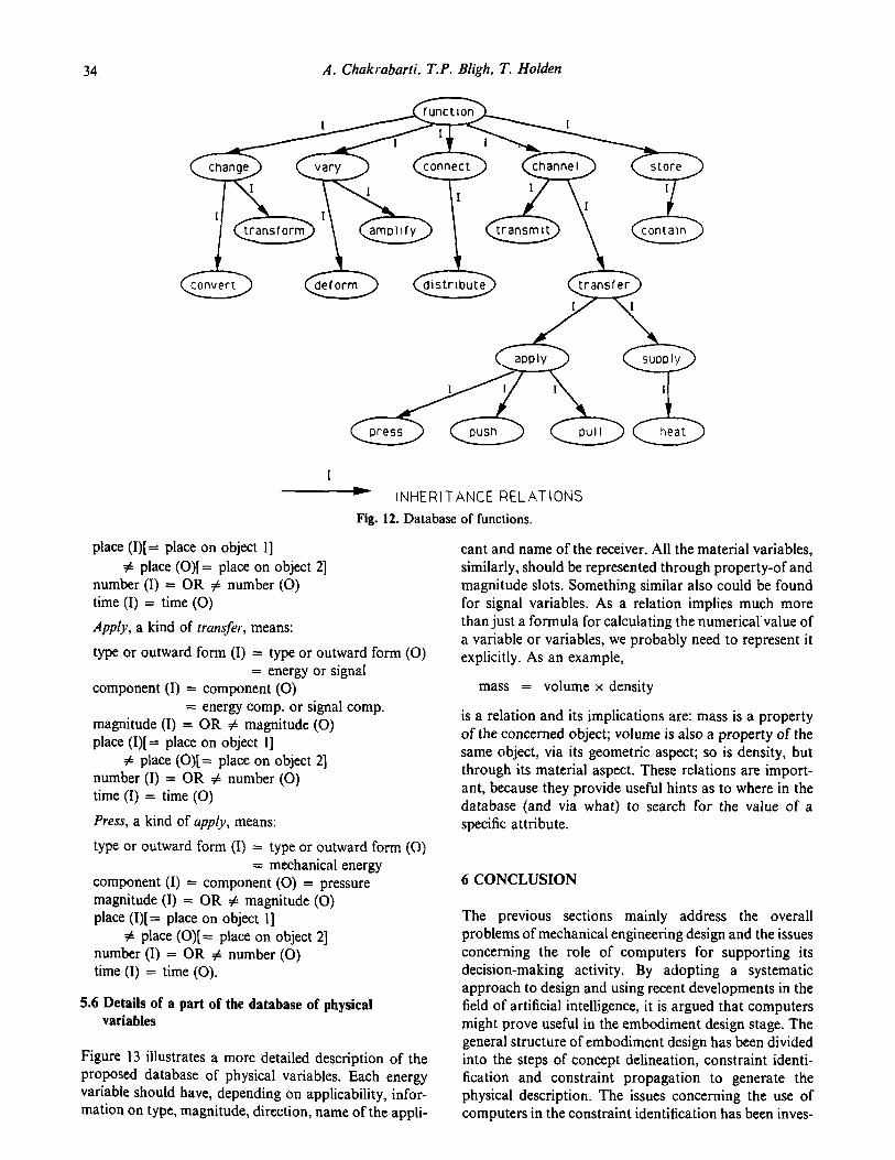
The generally valid functions in this definition become a set of functions having one common characteristic rather than just one function. Of these, specific functions represent the subsets. Look at Fig. 12, for instance, to follow the path channel-transfer-apply-press. Channel is represented by the following:
magnitude (I) = OR # magnitude (0) place (I) # place (0) number (I) = OR # number (0) time (I) = time (0)
Transfer, a kind of channel, means:
type OR outward form (I) = type OR outward form (0)
type or outward form (I) = type or outward form (0) component (I) = component (0)
Characteristic
Type
component (I) = component (0) magnitude (I) = OR # magnitude (0)
1 Generally valid
functions
Change
Symbols Explanations
Input (Q/Output (0
hoe mQ outward lorm ol
I and 0 duller
Magnitude Vary I<0 I>0
Number Connect Number 01 I > 0 Number 01 I c 0
Place Channel Place 01 I Z 0 Place 01 I = 0
Time Store Time ot I # 0
Fig. 11. Generally valid functions.”
34 A. Chakrabarti. T.P. Bligh. T. Holden
I
- INHERITANCE RELATIONS
Fig. 12. Database of functions.
place (I)[= place on object l] # place (O)[= place on object 21
number (I) = OR # number (0) time (I) = time (0)
Apply, a kind of transfer, means:
type or outward form (I) = type or outward form (0) = energy or signaI
component (I) = component (0) = energy camp. or signal camp.
magnitude (I) = OR # magnitude (0) place (I)[ = place on object l]
# place (O)[= place on object 2] number (I) = OR # number (0) time (I) = time (0)
Press, a kind of apply, means:
type or outward form (I) = type or outward form (0) = mechanical energy
component (I) = component (0) = pressure magnitude (I) = OR # magnitude (0) place (I)[= place on object l]
# place (O)[= place on object 23 number (I) = OR # number (0) time (I) = time (0).
5.6 Details of a part of the database of physical variables
Figure 13 illustrates a more detailed description of the proposed database of physical variables. Each energy variable should have, depending on applicability, infor- mation on type, magnitude, direction, name of the appli-
cant and name of the receiver. All the material variables, similarly, should be represented through property-of and magnitude slots. Something similar also could be found for signal variables. As a relation implies much more than just a formula for calculating the numerical’value of a variable or variables, we probably need to represent it explicitly. As an example,
mass = volume x density
is a relation and its implications are: mass is a property of the concerned object; volume is also a property of the same object, via its geometric aspect; so is density, but through its material aspect. These relations are import- ant, because they provide useful hints as to where in the database (and via what) to search for the value of a specific attribute.
6 CONCLUSION
The previous sections mainly address the overall problems of mechanical engineering design and the issues concerning the role of computers for supporting its decision-making activity. By adopting a systematic approach to design and using recent developments in the field of artificial intelligence, it is argued that computers might prove useful in the embodiment design stage. The general structure of embodiment design has been divided into the steps of concept delineation, constraint identi- fication and constraint propagation to generate the physical description. The issues concerning the use of computers in the constraint identification has been inves-

Towards a decision-SuDDort framework for the embodiment phase of mechanical design 35
2 area
property-of surface, geometry
magnl tude dIrectIon
+ INHERITANCE (A-KIND-OF) RELATlONS
a
EXISTANCE OF A RELATION AMONG THE
VARIABLES CONNECTED BY THIS SYMBOL
- INDICATES SHARED INFORMATION
Fig. 13. Details of a part of the database of physical variables.
tigated. A solution framework based on using behaviour as the pivotal element between purpose and structure is proposed and the suitability of a hierarchical object- oriented database is discussed. The resulting model would have a functional structure as well as a physical one, and this would make it much more useful. This research in progress is aimed at developing a symbolic language sufficiently powerful to support the constraint identification scheme on computers.
ACKNOWLEDGEMENTS
Amaresh Chakrabarti has been supported by the Nehru Trust for Cambridge University, India. The work has been carried out under the auspices of the Interactive Decision Support Project, the Science and Engineering Research Council, U.K.
REFERENCES
1. Chan, W.T. & Paulson, B.C. Jr. Exploratory design using
constraints, AI EDAM, 1987, l(l), 59-71. 2. Clayton, B.D. Inference ART programming manuals, Infer-
ence Corporation, California, 1985. 3. DeKleer, J. & Brown, J.S. A qualitative physics based on
confluences, ArtiJicial Intelligence, 1984, 24, 7-83. 4. Dyer, M.G., Flowers, M. & Hodges, J. EDISON: an engin-
eering design invention system operating naively, Appli- cation of AZ in Engineering, 1986, l(l), 36-44.
5. Freeman, P. & Newell, A. A model for functional reason- ing in design, Proc. Second ZJCAI, 1971, London, 621-640.
6. Forbus, K.D. Qualitative process theory, Artificial Zntelli- gence, 1984, 24, 7-83.
7. Hayes, P.J. The naive physics manifesto, Expert Sysrems in Micro-electronic Age, ed. D. Michie, Edinburgh University Press, Scotland, 1979, pp. 242-270.
8. Johnson, A.L. Functional modelling: a new development in computer-aided design, Proc. IFZP WG 5.2 Workshop on Intelligent CAD, Cambridge, UK, North Holland, 1988.
9. Kuipers, B. Commonsense reasoning about causality: deriving behavior from structure, Artificial Intelligence, 1984, 24, 169-203.
10. Pahl, G. & Beitz, W. Engineering design, The Design Council, London, 1984.
11. Popplestone, R.J. The application of artificial intelligence techniques to design systems, International Symposium on

36 A. Chakrabarti. T.P. Bligh, T. Holden
Design and Synthesis, Tokyo: Japan Society of Precision Engineering, 1984.
12. Popplestone, R.J. The Edinburgh designer system as a framework for robotics: the design of behaviour, AI EDAM, 1987, l(l), 25-36.
13. Su, S.Y.U. Modelling integral manufacturing data with SAM, IEEE Computer. 1986, January, pp. 34-39.
14. Ulrk$ K.T. & Seering, W.P. Synthesis of schematic descrip- tions m mechanical design, Research in Engineering Design, 1989, l(l), 3-18.