towards a 10 nm run-out rotation axis m. nicola, m
TRANSCRIPT
Towards a 10 nm Run-out Rotation axisM. Nicola, M. Hrouzek, M. Renier, M. Navizet, F. Comin
European Synchrotron Radiation Facility, BP 220, 38043 Grenoble Cedex, France
AbstractA 10 manometer precision rotation axis, or “Nanospindle”, is currently being developed tobe used on the ultra-high resolution Macromolecular Crystallography beamlines at theESRF.Since the best air bearing rotation tables available on the market guarantee an eccentricityin the 50 nm, with a wobble in the microradian range, a second stage including a real timefeedback system must be added to reach the requested ultimate precision. The maximumexpected rotation speed is limited to 500 rpm. The feedback system is based on a capacitivesensor spindle error analyser (Lion Precision), a Digital Signal Processor (SheldonInstruments) and two piezoelectric actuator assemblies (Jena Piezosystem). In a first phase,the prototype is being fully characterized at the Precision Engineering Lab, where itsstability, together with sensitivity to vibrations and temperature will be assessed. TheNanospindle will then be exported to ID23 where it will be tested in real operatingconditions for Multiple Anomalous Diffraction (MAD) experiments.The principle of operation of the Nanospindle, its design and some preliminary results of thetests on the prototype will be presented.
This development is supported by the SPINE II project under the European Union auspices.
1. Introduction
The commercially available air bearing rotary stages offer characteristics that, even if they areexcellent, are still insufficient to meet the current requests by the Biology community for very highresolution notably for the Multiple Anomalous Diffraction (MAD) experiments on macromolecules(mainly proteins).The problem will be even more severe on nanotomography experiments. Here the goal is to reach 10nm lateral resolution over a full revolution of the sample in the beam in order to avoid any blurringof the images after reconstruction of the tomographic pictures. Facing that problem, we have decidedto build an instrument which would compensate in real time the still existing eccentricity and wobbleon a commercially available air bearing rotary stage, with the ambitious goal of reaching theimposed 10 nm maximum eccentricity. As in any other regulation chain operating in closed loop, ourinstrument includes a device that measures the main shaft position, a programmable electroniccircuitry that amplifies the positioning error and sends an appropriate control voltage to the shaft re-positioning devices.The eccentricity is however not the only important parameter to be controlled. Its reduction mustalso be accompanied by a strict control of the wobble also present in the standard, high quality, airbearing rotation stages. The goal here is to get images of real tomographic planes and not of conesafter re-construction of the projections.The maximum speed of rotation, linked to the detector acquisition speeds, is limited to 500 rpm inour present device.
2. Commercially available air bearing rotary stages
The key component in the new instrument is the air bearing rotary stage, since it will support thewhole rotating assembly. It was therefore important to confirm the characteristics announced by thedifferent manufacturers at the time of the purchase. The measurements performed at the ESRFPrecision Engineering Laboratory indicated that both the eccentricity and the wobble were 5 to 10
times larger than the values specified by the manufacturers (25 to 250 nm eccentricity; 0.1 to 2.5mrad wobble without motor for the best units which makes them useless for our application). Finally,after the intervention of the manufacturer on one of the rotary axis available at the ESRF (AerotechABR 1000) [1], these values were reduced to twice the specified value. A final wobble value of 12mrad was measured. It was then decided that this latest value would be acceptable for our applicationsince it would be keeping the main rotary shaft within the re-positioning range of our actuators.
3. Principle of operation
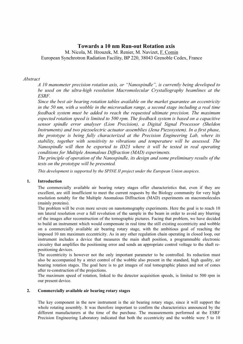
Two identical assemblies of two stainless steel flexors, 1.5 mm thick, support the main shaft on theair bearing rotary table (Aerotech ABR 1000).
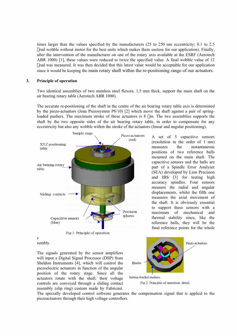
The accurate re-positioning of the shaft in the centre of the air bearing rotary table axis is determinedby the piezo-actuators (Jena Piezosystem P8/10) [2] which move the shaft against a pair of spring-loaded pushers. The maximum stroke of these actuators is 8 mm. The two assemblies supports theshaft by the two opposite sides of the air bearing rotary table, in order to compensate for anyeccentricity but also any wobble within the stroke of the actuators (linear and angular positioning).
A set of 5 capacitive sensors(resolution in the order of 1 nm)measures the instantaneouspositions of two reference ballsmounted on the main shaft. Thecapacitive sensors and the balls arepart of a Spindle Error Analyser(SEA) developed by Lion Precisionand IBS [3] for testing highaccuracy spindles. Four sensorsmeasure the radial and angulardisplacements, whilst the fifth onemeasures the axial movement ofthe shaft. It is obviously essentialto support these sensors with amaximum of mechanical andthermal stability since, like thereference balls, they will be thefinal reference points for the whole
assembly.
The signals generated by the sensor amplifierswill input a Digital Signal Processor (DSP) fromSheldon Instruments [4], which will control thepiezoelectric actuators in function of the angularposition of the rotary stage. Since all theactuators rotate with the shaft, their voltagecontrols are conveyed through a sliding contactassembly (slip ring) custom made by Fabricast.The specially developed control software generates the compensation signal that is applied to thepiezoactuators through their high voltage controllers.
The XYZ positioning table at the top of the instrument is used to re-position the region of interest ofthe sample in the accurate axis of rotation determined by the whole assembly. The Z channelhowever is linked to the fifth sensor at the bottom of the assembly, and will compensate for possibleaxial displacements.
4. Construction details
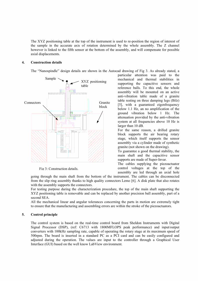
The “Nanospindle” design details are shown in the Autocad drawing of Fig 3. As already stated, aparticular attention was paid to themechanical and thermal stabilities insupporting the capacitive sensors andreference balls. To this end, the wholeassembly will be mounted on an activeanti-vibration table made of a granitetable resting on three damping legs (Bilz)[5], with a guaranteed eigenfrequencybelow 1.1 Hz, an no amplification of theground vibration below 1 Hz. Theattenuation provided by the anti-vibrationsystem at all frequencies above 10 Hz islarger than 10 dB.For the same reason, a drilled graniteblock supports the air bearing rotarystage, which itself supports the sensorassembly via a cylinder made of syntheticgranite (not shown on the drawing).To guarantee a good thermal stability, themain shaft and the capacitive sensorsupports are made of Super-Invar.The cables supplying the piezoactuatorcontrol voltages at the top of theassembly are led through an axial hole
going through the main shaft from the bottom of the instrument. The cables can be disconnectedfrom the slip ring assembly thanks to high quality connectors Lemo [6]. A disk plate that also rotateswith the assembly supports the connectors.For testing purpose during the characterization procedure, the top of the main shaft supporting theXYZ positioning table is removable and can be replaced by another precision ball assembly, part of asecond SEA.All the mechanical linear and angular tolerances concerning the parts in motion are extremely tightto ensure that the manufacturing and assembling errors are within the stroke of the piezoactuators.
5. Control principle
The control system is based on the real-time control board from Sheldon Instruments with DigitalSignal Processor (DSP), (ref: C6713 with 1800MFLOPS peak performance) and input/outputconverters with 100kHz sampling rate, capable of operating the rotary stage at its maximum speed of500rpm. The board is inserted in a standard PC as a PCI card and can be easily configured andadjusted during the operation. The values are input to the controller through a Graphical UserInterface (GUI) based on the well know LabView environment.
Fig 3: Construction details.
Graniteblock
Connectors
XYZ positioningtable
Sample
The control system can be divided into two parts:
• The real time operating system runs directly on the DSP and simultaneously executes theprogram of the programmed controllers. The eccentricity and wobble of the shaft are measured withrespect to the reference axis of the system determined by the granite table. The actuators aremounted on the rotating part of the stage and their actuation is corresponding to the relative axis ofthe rotating table. The program has to mathematically transform the measured position errors withrespect to the reference axis into the current relative angular position. The generated error signals areused to control the actuators. The fifth vertical sensor directly controls the axial position using the Zmotion of the Minitritor XYZ positioning table.
• The user interface has two main functionalities. It displays the actual eccentricity, wobbleand position of the XYZ positioning table and it also provides the possibility of directly commandingthe Minitritor positioning table. All parameters of the shaft position controllers can be as welladjusted according to the specific mode of operation (step operation or continuous rotation) and tothe user needs.
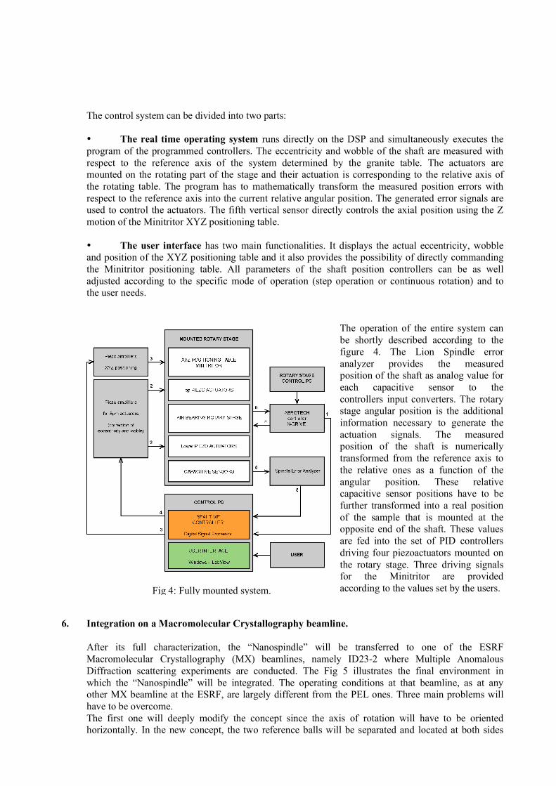
The operation of the entire system canbe shortly described according to thefigure 4. The Lion Spindle erroranalyzer provides the measuredposition of the shaft as analog value foreach capacitive sensor to thecontrollers input converters. The rotarystage angular position is the additionalinformation necessary to generate theactuation signals. The measuredposition of the shaft is numericallytransformed from the reference axis tothe relative ones as a function of theangular position. These relativecapacitive sensor positions have to befurther transformed into a real positionof the sample that is mounted at theopposite end of the shaft. These valuesare fed into the set of PID controllersdriving four piezoactuators mounted onthe rotary stage. Three driving signalsfor the Minitritor are providedaccording to the values set by the users.
6. Integration on a Macromolecular Crystallography beamline.
After its full characterization, the “Nanospindle” will be transferred to one of the ESRFMacromolecular Crystallography (MX) beamlines, namely ID23-2 where Multiple AnomalousDiffraction scattering experiments are conducted. The Fig 5 illustrates the final environment inwhich the “Nanospindle” will be integrated. The operating conditions at that beamline, as at anyother MX beamline at the ESRF, are largely different from the PEL ones. Three main problems willhave to be overcome.The first one will deeply modify the concept since the axis of rotation will have to be orientedhorizontally. In the new concept, the two reference balls will be separated and located at both sides
Fig 4: Fully mounted system.
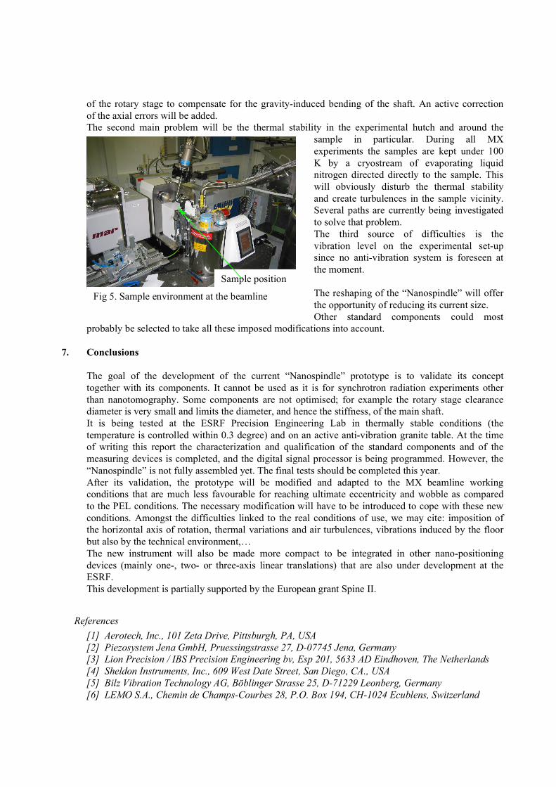
of the rotary stage to compensate for the gravity-induced bending of the shaft. An active correctionof the axial errors will be added.The second main problem will be the thermal stability in the experimental hutch and around the
sample in particular. During all MXexperiments the samples are kept under 100K by a cryostream of evaporating liquidnitrogen directed directly to the sample. Thiswill obviously disturb the thermal stabilityand create turbulences in the sample vicinity.Several paths are currently being investigatedto solve that problem.The third source of difficulties is thevibration level on the experimental set-upsince no anti-vibration system is foreseen atthe moment.
The reshaping of the “Nanospindle” will offerthe opportunity of reducing its current size.Other standard components could most
probably be selected to take all these imposed modifications into account.
7. Conclusions
The goal of the development of the current “Nanospindle” prototype is to validate its concepttogether with its components. It cannot be used as it is for synchrotron radiation experiments otherthan nanotomography. Some components are not optimised; for example the rotary stage clearancediameter is very small and limits the diameter, and hence the stiffness, of the main shaft.It is being tested at the ESRF Precision Engineering Lab in thermally stable conditions (thetemperature is controlled within 0.3 degree) and on an active anti-vibration granite table. At the timeof writing this report the characterization and qualification of the standard components and of themeasuring devices is completed, and the digital signal processor is being programmed. However, the“Nanospindle” is not fully assembled yet. The final tests should be completed this year.After its validation, the prototype will be modified and adapted to the MX beamline workingconditions that are much less favourable for reaching ultimate eccentricity and wobble as comparedto the PEL conditions. The necessary modification will have to be introduced to cope with these newconditions. Amongst the difficulties linked to the real conditions of use, we may cite: imposition ofthe horizontal axis of rotation, thermal variations and air turbulences, vibrations induced by the floorbut also by the technical environment,…The new instrument will also be made more compact to be integrated in other nano-positioningdevices (mainly one-, two- or three-axis linear translations) that are also under development at theESRF.This development is partially supported by the European grant Spine II.
References
[1] Aerotech, Inc., 101 Zeta Drive, Pittsburgh, PA, USA[2] Piezosystem Jena GmbH, Pruessingstrasse 27, D-07745 Jena, Germany[3] Lion Precision / IBS Precision Engineering bv, Esp 201, 5633 AD Eindhoven, The Netherlands[4] Sheldon Instruments, Inc., 609 West Date Street, San Diego, CA., USA[5] Bilz Vibration Technology AG, Böblinger Strasse 25, D-71229 Leonberg, Germany [6] LEMO S.A., Chemin de Champs-Courbes 28, P.O. Box 194, CH-1024 Ecublens, Switzerland
Sample position
Fig 5. Sample environment at the beamline