toward energy harvesting using active materials...
TRANSCRIPT
584 ieee transactions on ultrasonics, ferroelectrics, and frequency control, vol. 52, no. 4, april 2005
Toward Energy Harvesting Using ActiveMaterials and Conversion Improvement by
Nonlinear ProcessingDaniel Guyomar, Adrien Badel, Elie Lefeuvre, and Claude Richard
Abstract—This paper presents a new technique of elec-trical energy generation using mechanically excited piezo-electric materials and a nonlinear process. This technique,called synchronized switch harvesting (SSH), is derivedfrom the synchronized switch damping (SSD), which is anonlinear technique previously developed to address theproblem of vibration damping on mechanical structures.This technique results in a significant increase of the elec-tromechanical conversion capability of piezoelectric materi-als. Comparatively with standard technique, the electricalharvested power may be increased above 900%. The per-formance of the nonlinear processing is demonstrated onstructures excited at their resonance frequency as well asout of resonance.
I. Introduction
Piezoelectric solid state microgenerators are basedon the electromechanical energy conversion taking
place in a piezoelectric material. Such a generator usuallyincludes a mechanical device designed to apply a drivingstress on piezoelectric elements. The piezoelectric elementsacting as the generator are connected together to an elec-trical network constituting the energy receiver. The alter-nating voltage on the piezoelectric elements electrodes de-pends on the mechanical solicitation and on the energyreceiver behavior.
Piezoelectric microgenerators comply with durable de-velopment requirements, offering an alternative to button-type battery cells for remote vibrating systems. They offerwireless and lower maintenance. They can supply electricaldevices with very low average power requirements (lowerthan one Watt), such as sensors [1], [2], remote controldevices [3], or any device able to accumulate a sufficientamount of energy for an intermittent use under a higherpeak power [4].
Two types of piezoelectric microgenerators can be dis-tinguished: first, generators under quasistatic stress con-ditions that are excited far lower than their resonance fre-quency; and second, generators under dynamic stress con-ditions that are excited near their resonance frequency.Generators under dynamic stress conditions are more effi-
Manuscript received April 1, 2004; accepted October 20, 2004.The authors are with the Laboratoire de Genie Electrique
et Ferroelectricite, Institut National des Sciences Appliquees(INSA) de Lyon, 69621 Villeurbanne, France (e-mail: [email protected]).
cient [5], and the technique presented here increase theirperformance significantly.
Electronic devices generally require direct current (DC)supply voltages. For this reason, the alternative voltage de-livered by the piezoelectric elements is converted using analternating current (AC)-to-DC converter. This converteris often simply composed of a diodes rectifier bridge andan output filtering capacitor. But in some more sophis-ticated systems, the AC-to-DC converter is followed bya DC-to-DC converter used for impedance adaptation orsupply voltage regulation [6], [7].
The technique proposed herein is an alternative newmethod for increasing the converted energy flow resultingfrom a given mechanical loading cycle [8], [9]. This tech-nique is fully compatible with the standard approach. Theso-called standard approach is actually the simplest wayto envision a load supply. In the AC voltage case it con-sists in connecting the load directly with the piezoelectricelements, and in the DC voltage case the load is connectedthrough a rectifier. The proposed technique consists inadding up a nonlinear processing, achieved by an electricalswitch device connected to the piezoelectric elements. Thisnonlinear switching process artificially increases the piezo-electric elements output voltage, resulting in a significantincrease of the electrical power flow. The switch device istriggered on the maxima and minima of the displacement,and it briefly realizes the inversion of the voltage throughan oscillating process. This device can be self powered. Italso can be triggered on the piezoelectric elements voltageitself, then does not need a sensor.
The converted energy strongly depends on the mechan-ical solicitation and on the global electromechanical cou-pling factor.
A simple electromechanical modeling of a structure withpiezoelectric elements is proposed. The AC and DC out-put, with and without the proposed nonlinear processing,are developed and compared experimentally and theoreti-cally. In some cases, a significant mechanical damping ef-fect is induced by energy harvesting [10]. This behavior istaken into account by the model.
Experimental results obtained on a cantilever beamwith piezoelectric elements bonded on its surface are dis-cussed. They are in good agreement with the given predic-tions. Both results confirm that the harvested power canbe increased above 900% compared to standard techniquefor a given vibration amplitude of the beam.
0885–3010/$20.00 c© 2005 IEEE
guyomar et al.: electrical energy generation using new technique 585
Fig. 1. Equivalent model of a vibrating structure with piezoelectricelements bonded on it.
TABLE IPiezoelectric Parameters Definitions.
A Piezoelectric disk sectionL Piezoelectric disk thickness
cE33 Elastic rigidity of the piezoelectric disk short-circuited
cD33 Elastic rigidity of the piezoelectric disk open-circuited
εS33 Clamped permittivity of the piezoelectric disk
εT33 Null stress permittivity of the piezoelectric disk
e33 Piezoelectric coefficient of the piezoelectric disk
II. Modeling
The considered microgenerator includes a vibrating me-chanical structure with bonded piezoelectric elements. Ifthis structure is excited around its resonance frequencyand for little displacements for which the movement re-mains linear, then the structure with piezoelectric elementscan be modeled by a {mass+piezo+spring+damper} sys-tem such as the one shown in Fig. 1.
In this simple approach, the considered structure is arigid mass M bonded on a spring KS corresponding tothe stiffness of the mechanical structure, on a damper Ccorresponding to the mechanical losses of the structure,and on a piezoelectric disk with a thickness L and a sectionA corresponding to the bonded piezoelectric elements.
The rigid mass M undergoes the action of both externaland internal forces. The external force F is the mechanicalexcitation applied to the structure. The internal force canbe separated in a restoring force FP due to the piezoelectricdisk, in a restoring force due to the spring, and in a viscousforce due to the damper.
The mass displacement is u, I and V are the outgoingcurrent and the voltage on the piezoelectric disk that isconnected on the energy harvesting device.
The piezoelectric equations (1) link the mechanical vari-able (u, FP ) and the electrical ones (I, V ); KPE is the stiff-ness of the piezoelectric disk when it is short-circuited, C0is its clamped capacitance, and α is the force factor:
{Fp = KPEu + αV
I = αu − C0V. (1)
The equations (2) give the expression of KPE , C0, and αas a function of the piezoelectric parameters described inTable I.
KPE =cE33A
L, C0 =
εS33A
L, α =
e33A
L. (2)
The electromechanical coupling factor of the piezoelectricdisk is kt (3) and its stiffness when it is short-circuited isKPD (4):
k2t =
e233
εT33c
E33
=e233
εS33c
E33 + e2
33=
α2
C0KPE + α2 . (3)
KPD =cD33A
L=
KPE
1 − k2t
. (4)
As the restoring force due to the stiffness of the mechan-ical structure and the restoring force due to the stiffnessof the piezoelectric disk act in the same way on the massM , a global stiffness for both mechanical structure andpiezoelectric disk can be defined (5) when the piezoelec-tric disk is short circuited (KE) and open circuited (KD).The electromechanical coupling factor k corresponding tothe global system, including the mechanical structure andthe piezoelectric disk, then can be expressed (6) as a func-tion of the force factor α, the clamped capacitance C0, andthe global stiffness KE . This global coupling factor is, ofcourse, lower than the intrinsic coupling factor kt of thepiezoelectric disk.
{KE = KPE + KS
KD = KPD + KS
. (5)
k2 =α2
KEC0 + α2 =α2
KDC0. (6)
Expression (7), defining the dynamic equilibrium of thesystem governs the displacement u of the mass M . Theenergy equation (8) is obtained by multiplying both termsof (7) by the velocity and integrating over the time vari-able. The provided energy is divided into kinetic energy,potential elastic energy, mechanical losses, and transferredenergy. The transferred energy corresponds to the part ofmechanical energy that is converted into electrical energy.It is the sum of the electrostatic energy stored on the piezo-electric disk and the energy absorbed by the connectedelectrical device (9):
Mu = F − KEu − αV − Cu. (7)∫
Fudt =12Mu2 +
12KEu2 +
∫Cu2dt +
∫αV udt.
(8)∫
αV udt =12C0V
2 +∫
V Idt. (9)
III. Energy Harvesting Device
The aim of this section is to express the harvested poweras a function of the electric load supplied by the micro-generator and the different parameters of the model, in

586 ieee transactions on ultrasonics, ferroelectrics, and frequency control, vol. 52, no. 4, april 2005
Fig. 2. Standard AC device.
Fig. 3. Standard DC device.
the case of a permanent sinusoidal mechanical excitation.In the entire article and, in particular, in this section, theharvested power expressions always correspond to the av-erage power. The electrical harvested power is expressedfor standard harvesting devices and for harvesting deviceswith nonlinear processing.
A. Standard Device
It is considered a so-called piezoelectric energy harvest-ing device that supplies an electrical network, either di-rectly or through a rectifier and a storage element (capaci-tor, accumulator). If this supplied electrical network has alinear behavior, it can be represented simply by its inputimpedance.
In a first approach, we consider a purely resistive loaddirectly connected on the piezoelectric element (Fig. 2). Inthis case, the voltage on the load R is alternative. A morerepresentative approach considering real applications con-sists in including a rectifier followed by a filtering capacitorCr (Fig. 3). In this case, if the RCr time constant is largecompared to the vibration period, the voltage Vcc on theload R can be considered as continuous.
1. AC Standard Device: The external excitation forceF applied to the structure is considered as purely sinu-soidal with a frequency closed to the resonance frequencyof the structure with the loaded piezoelectric element (theelectrical load may induce little shift of the resonance fre-quency).
Considering the second piezoelectric equation and theresistance of the load, the voltage on the piezoelectric ele-ment can be expressed in the frequency domain as a func-tion of the displacement (10), where ω is the angular fre-quency.
V =αR
1 + jRC0ωjωu. (10)
Expression (11) linking force and displacement is ob-tained using (7) written in the frequency domain and (10):
F =(
jMω +1jω
KE + C +α2R
jRC0ω + 1
)jωu.
(11)
At resonance, it can be considered that the force F andthe speed u are in phase (this is a good approximation forstructures with low viscous losses). Expression (11) is thensimplified and leads to (12):
F =
(
C +α2R
(RC0ω)2 + 1
)
jωu. (12)
Starting from (10), the harvested power can be ex-pressed as a function of the displacement amplitudeum (13):
P =V V ∗
2R=
Rα2
1 + (RC0ω)2ω2u2
m
2. (13)
Using (12), it then is possible to give a general expres-sion of the harvested average power as a function of theexternal force amplitude Fm, the load R, and the variousmodel parameters (14):
P =F 2
m
2Rα2
1 + (RC0ω)21
(
C +Rα2
1 + (RC0ω)2
)2 .(14)
For weakly electromechanically coupled structure, thevariable α is closed to zero, which leads to a simplifiedexpression of the harvested power (15). In this case theharvested power reaches a maximum Pmax for an optimalload Ropt:
P =Rα2
1 + (RC0ω)2F 2
m
2C2 . (15)
Ropt =1
C0ωand Pmax =
α2
4C0ω
F 2m
C2 . (16)
It also can be noticed that, in the case of systems drivenout of their own resonance, for which the displacementamplitude remains practically constant whatever the load,and in the case of systems in which the displacement isforced, the power reaches also a maximum for the sameoptimal load Ropt, as it can be obviously derived from (13).
2. DC Standard Device: As in the previous case, it isconsidered a harmonic force F applied to the structure. Arectifier followed by a filtering capacitance Cr and the loadR are connected to the piezoelectric element (Fig. 3). Therectifier is assumed to be perfect and the rectified voltageVcc is assumed to be constant, which is a good approxi-mation if the time constant RCr is much larger than theoscillating period of the structure. In these conditions, theaverage current flowing through the filtering capacitanceis null during a half oscillating period.

guyomar et al.: electrical energy generation using new technique 587
Fig. 4. Voltage and displacement typical waveforms for the standardDC device.
When the piezo voltage V is lower than the rectifiedvoltage Vcc, the rectifier is open circuited, then the out-going piezo current I is null and, therefore, the voltageand the displacement vary proportionally, as shown by (1).However, when the piezo voltage V reaches Vcc, the recti-fier conducts and the voltage V is blocked at Vcc. The con-duction is again cancelled when the displacement u startto decrease. Typical voltage and displacement waveformsare shown in Fig. 4.
It is considered the electric charge generated by thepiezoelectric element during a particular semiperiod (be-tween instant t1 and t2). This charge is the integral overthe time of the current I between t1 and t2 and also can berepresented by the electric charge that has flown throughthe load R during the same semiperiod because the aver-age current flowing through Cr is null (17). Starting from(17) and considering the second piezoelectric equation (1),the rectified voltage Vcc can be expressed as a function ofthe displacement amplitude um (18):
t2∫
t1
Idt =Vcc
R
T
2. (17)
Vcc =Rα
RC0ω +π
2
ωum. (18)
It then is considered the energy balance of the struc-ture during the same semiperiod. The provided energy isequal to the sum of the mechanical losses and the energyharvested on the load (19) because there is no variation ofthe potential elastic energy between instant t1 and t2 andthe kinetic energy is null at those instants:
T/2∫
0
Fudt = C
T/2∫
0
u2dt +V 2
cc
R
T
2. (19)
At resonance, assuming that the displacement remainssinusoidal, the energy balance (19) can be simplified, andthe displacement amplitude um then can be expressed asa function of the applied force amplitude Fm (20):
um =Fm
Cω +2Rωα2
(RC0ω +
π
2
)2
. (20)
Fig. 5. Nonlinear device and voltage, displacement and speed typicalwaveforms when no load is connected.
The harvested power can be expressed as a functionof the displacement amplitude (21), then, using (20) and(21), it can be expressed as a function of the applied forceamplitude Fm, the load R, and the various parameters ofthe model:
P =V 2
cc
R=
Rα2
(RC0ω +
π
2
)2 ω2u2m. (21)
For a weakly electromechanically coupled structure, theexpression of the harvested power can be simplified and isdefined by (22). In this case, the harvested average powerreaches a maximum Pmax for an optimal load Ropt (23):
P =Rα2
(RC0ω +
π
2
)2F 2
m
C2 . (22)
Ropt =π
2C0ωand Pmax =
α2
2πC0ω
F 2m
C2 . (23)
For a structure driven out of its resonance or for a struc-ture in which the displacement is forced, the power reachesa maximum for the same optimal load Ropt, as it can bederived from (21).
B. Nonlinear Device
The technique proposed in this paper, called synchro-nized switch harvesting on inductor (SSHI) consists inadding up a switching device in parallel with the piezoelec-tric element as shown in Fig. 5. This device is composedof a switch and an inductance LI connected in series. Theswitch is almost always open, except when a displacementextremum occurs. At this instant, the switch is closed. Thecapacitance C0 of the piezoelectric element and the induc-tance LI then constitute an oscillator. The switch is keptclosed until the voltage on the piezoelectric element hasbeen reversed, as shown in Fig. 6. It corresponds to a timeti equal to a half period of the oscillator. The lower is theinductance LI , the shorter will be ti. Thus, this techniquedoes not require a high inductance value:
ti = π√
L1C0. (24)
When the switch is open and if no load is connected,the outgoing piezo current I is null, then the voltage Vand the displacement u vary proportionally.

588 ieee transactions on ultrasonics, ferroelectrics, and frequency control, vol. 52, no. 4, april 2005
Fig. 6. Piezoelement voltage inversion.
The voltage inversion is not perfect because a part ofthe energy stored on the piezoelectric element capacitanceis lost in the switching network (transistor + self) and bythe high frequency radiation due to the sharp edges of thevoltage signal. Therefore, this degrades the quality factorQI that can be defined for the inversion oscillating network(Fig. 6).
This nonlinear processing on the piezoelectric elementvoltage has two effects: First, the amplitude of the voltageis always increasing, except during the inversion process.Second, the voltage V always has the same sign as thespeed (Fig. 5). It follows from these two points that thetransferred energy Et (defined in Table II) is optimized.
In this simple case, the transferred energy is dissipatedinto heat by Joule effect and by the high-frequency energyradiation. However, the voltage magnification and the re-lated transferred energy increase are strong arguments forusing this approach to supply a load with this particularnonlinear piezoelectric energy harvesting device.
1. Nonlinear AC Device: In this case, a resistive load Ris directly connected on the piezoelectric element in par-allel with the switching device. Typical waveforms of thevoltage V and the displacement u are given in Fig. 7. Ex-cept during the inversion process, the differential equationlinking the voltage and the displacement is given by (25).The displacement is assumed to remain sinusoidal, whichappears to be a valid assumption, even for strongly cou-pled structure. Expression (25) is solved between instant0 and T/2, with the boundary conditions defined as (26),which leads to the variation of the voltage between twoinversions defined by (27):
V
R= αu − C0V . (25)
u = −um cos(ωt) and V (0) = V (T/2)e−π2QI .
(26)
V (t) =αum
C0
(RC0ω)2
1 + (RC0ω)2
[1 + e
π2QI
eπ
2QI − e−π
RC0ω
]
e−t
RC0
− αum
C0
RC0ω√1 + (RC0ω)2
cos(
ωt + arctan(
1RC0ω
)).(27)
Considering the energy balance between instant 0 andT/2, it is pointed out that the energy injected by the driv-
TABLE IIEnergetic Terms Definitions.
∫F udt Provided energy
12
Mu2 Kinetic energy12
KEu2 Potential elastic energy∫
Cu2dt Mechanical losses∫αV udt Transferred energy
Fig. 7. Nonlinear AC device and associated voltage and displacementtypical waveforms.
ing force during this semiperiod corresponds to the sumof the mechanical losses, the losses due to the switch pro-cess, and the harvested energy. The switch-related lossesare the difference between the electric potential energy onthe piezoelectric element capacitance before and after theswitch (28):
T/2∫
0
Fudt = C
T/2∫
0
u2dt
+12C0V (T/2)2
(1 − e
−πQI
)+
1R
T/2∫
0
V (t)2dt. (28)
Expression (27) shows that the voltage V is equal tothe product of a time-dependant function and of the dis-placement amplitude um (29):
V (t) = γ(t)um, γ2eff =
2T
T/2∫
0
γ(t)2 and γm = γ(T/2).(29)
At the resonance, assuming that the displacement issinusoidal and using (29), the energy balance representedby (28) can be simplified. This leads to the expressionof the displacement amplitude um as a function of theamplitude of the force Fm applied to the structure (30):
um =Fmπ
πCω +γ2
eff
R
2π
ω+ C0γ
2m
(1 − e
−πQI
) .(30)
The harvested power can be expressed as a functionof the displacement amplitude (31), then, using (30) and

guyomar et al.: electrical energy generation using new technique 589
Fig. 8. Nonlinear DC device.
(31), the harvested power can be expressed as a functionof the applied force amplitude Fm, the load R, and thevarious parameters of the structure model:
P =γ2
eff
2Ru2
m. (31)
In the case of either weakly coupled structures, or struc-tures driven out of their resonances, or structures in whichthe displacement is forced—that corresponds to the case inwhich the displacement amplitude remains constant withthe load for a given applied force—the harvested powerreaches a maximum for an optimal load, but it is difficultto give a simple analytical expression for it.
2. Nonlinear DC Device: Compared to the standardDC device described in Section III-A, the switching deviceis added in parallel on the piezoelectric element as shownon Fig. 8. Typical waveforms of the voltage V and thedisplacement u are shown in Fig. 9, assuming that therectified voltage Vcc remains constant.
The electric charge generated by the piezoelectric ele-ment between instant t1 (before inversion) and t2 (beforeinversion) is considered. This charge is the integral over thetime of the current I between t1 and t2 and can be rep-resented by the electric charge that has flown through theload R and through the switching device during the samesemiperiod (32). The current flowing through the switchis always null, except during the voltage inversion, just af-ter the instant t1, where it is proportional to the voltagetime derivative. The electric charge flowing through theswitching device then can be calculated (33):
t2∫
t1
Idt +
t2∫
t1
iSdt =Vcc
R
T
2. (32)
t2∫
t1
iSdt = C0
t1+ti∫
t1
dV = C0Vcc
(1 + e
−π2QI
).
(33)
Using (32) and (33), and considering the second equa-tion of the piezoelectric system (1), the rectified voltageVcc can be expressed as a function of the displacementamplitude um (34):
Vcc =2Rα
RC0
(1 − e
−π2QI
)ω + π
ωum. (34)
Fig. 9. Typical voltage and displacement waveforms for the nonlinearDC device.
Again, the energy balance during the same semiperiodis considered; and, according to the previous case, the en-ergy injected by the driving force during this semiperiodcompensates for the mechanical losses, the losses due tothe switch process, and the harvested energy (35):
T/2∫
0
Fudt = C
T/2∫
0
u2dt +12C0V
2cc
(1 − e
−πQI
)+
V 2cc
R
T
2.(35)
At the resonance, with the same assumption as that inthe AC case, the energy balance equation (35) can be sim-plified, which leads to the expression of the displacementamplitude um as a function of the amplitude Fm of theforce applied to the structure (36):
um =Fm
Cω +4Rωα2
π
(RC0
(1 − e
−πQI
)ω + 2π
)
(RC0
(1 − e
−π2QI
)ω + π
)2
.(36)
The harvested power can be expressed as a functionof the displacement amplitude (37); then, using (36) and(37), it can be expressed as a function of the applied forceamplitude Fm, the load R, and the various parameters ofthe model:
P =V 2
cc
R=
4Rα2
(RC0
(1 − e
−π2QI
)ω + π
)2 ω2u2m.
(37)
For structures with a weak electromechanical coupling,the expression of the harvested power can be simplifiedand is defined as in (38). In this case, the harvested powerreaches a maximum Pmax for an optimal load Ropt (39).For a structure driven out of its resonance or for a structurein which the displacement is forced, the power reaches amaximum for the same optimal load Ropt:
P =4Rα2
(RC0
(1 − e
−π2QI
)ω + π
)2F 2
m
C2 . (38)
Ropt =π
C0
(1 − e
−π2QI
)ω
and
Pmax =α2
πC0
(1 − e
−π2QI
)ω
F 2m
C2 .(39)

590 ieee transactions on ultrasonics, ferroelectrics, and frequency control, vol. 52, no. 4, april 2005
In (39), the maximum of the harvested power appearsto be a function of the inversion quality factor QI . If thecondition (40) is satisfied, then the maximum harvestedpower can be approximated by (41). This means that, for aweakly coupled structure, for structures driven out of theirresonances, or for structures in which the displacement isforced, the harvested power is proportional to the inversionquality factor, providing that this factor is large enough.The optimization of this nonlinear technique then inducesa maximization of this quality factor QI :
QI � π
2. (40)
Pmax =α2QI
π2C0ω
F 2m
2C2 . (41)
IV. Theoretical Comparisons of the Different
Techniques
In this section, SSHI energy harvesting is compared tothe standard technique on a modeling base. Two cases areconsidered. In the first case, the harvested power is ob-tained in a configuration in which the vibration amplitudeis not affected by the supplied load R, nor by the processapplied to the voltage V delivered by the piezoelectric ele-ment. This case corresponds to weakly coupled structures,structures driven out of their resonances, or any case witha forced displacement.
In the second case, the structure is excited at the reso-nance frequency. The driven force is imposed, and due tothe damping effect the vibration amplitude is affected as afunction of the electromechanical coupling factor. In thiscase, the energy reclamation is linked to a damping effectthat increases with the electromechanical coupling factor.
A. Weakly Coupled Structures
Using (15), (22), (31), and (38), the harvested power canbe expressed for each device as a function of the load R,the force amplitude Fm, and the parameters of the model.
The case of structures driven out of their resonance fre-quencies or structures in which the displacement is forcedare similar because in each case the displacement ampli-tude remains constant versus the load R. The harvestedpower then can be calculated using (13), (21), (31), and(37) that are similar to the previous ones.
Fig. 10 shows the variation of the harvested power as afunction of the resistive load R for each technique usedwith the same mechanical structure. The curves corre-sponding to the SSHI technique are given for an inversionquality factor QI equal to 2.6, which corresponds to a pre-liminary experimental setup. The interest of the nonlineartechnique is clearly demonstrated, with an output powerincrease in the DC case greater than 400% compared tothe standard technique. The latest experimental setup, us-ing an improved resonator with an inversion quality factorQI greater than 5, exhibits an output power increase by afactor close to 10.
Fig. 10. Harvested power versus the load R for the same displacementamplitude (α = 0.0035 N/V, KE = 22000 Nm−1, M = 444 g, C0 =55.8 nF, QI = 2.6, um = 0.6 mm).
Fig. 11. Energy conversion cycles for the optimal load of each har-vesting circuit (α = 0.0035 N/V, KE = 22000 Nm−1, M = 444 g,C0 = 55.8 nF, QI = 2.6, um = 0.33 mm).
Fig. 11 derives from a numerical time-domain resolutionof (7). It illustrates the benefit due to the proposed switch-ing technique, showing energy conversion cycle for the con-sidered structure. Piezoelectric generated force αV is di-rectly proportional to the piezoelement voltage. It is plot-ted as a function of the mass displacement u or piezoele-ment elongation for a few time periods for various har-vesting circuits, with the optimal load of each technique.The transferred energy defined in Table II corresponds toa period to the area Ac delimited by the cycles, as it canbe derived from (42):
Ac =∫
αV du =
T∫
0
αV udt. (42)

guyomar et al.: electrical energy generation using new technique 591
Clearly, the strong voltage magnification and quadra-ture phase resulting from the SSHI process allows one toextend largely these cycles along the force axis, resultingin an improved energy amount for a given vibration am-plitude.
In the case of nonlinear techniques, the transferred en-ergy is hardly greater than the harvested energy because aweak part of this energy is lost during the switch process.
It can be noticed that the energy conversion cycles forfor SSHI technique are larger for the DC case than forthe AC case, which is a great difference compared to thestandard techniques.
It is also interesting to note that the main limitationis due to the inversion quality factor QI . In the case con-sidered here, it has been limited to 2.6, which correspondsto a preliminary experimental setup. However, a properchoice of the material associated with a correct switchand inversion inductance design could lead to a drasticimprovement of the voltage inversion and, therefore, cy-cle area and harvested energy. In the latest experimentalsetup, the inversion quality factor is greater than 5.
B. Harvested Energy as a Function of the GlobalElectromechanical Coefficient
On a structure driven at the resonance frequency, theharvested power can be expressed as a function of the am-plitude of the applied force Fm, whatever the electrome-chanical coupling factor. In this case the displacement am-plitude does not remain constant, and the amount of ex-tracted energy is strongly related to a structural dampingeffect.
For a given mechanical structure, the harvested powercan be predicted as a function of the piezoelectric mate-rial quantity. Indeed, it can be noticed that, if the areaof piezoelectric elements is doubled, then the clamped ca-pacitance C0 is also doubled, as well as the force factor α,provided that the added piezoelectric elements are placedin the same area as the previous ones so they have thesame electromechanical effect. If the open-circuit stiffnessKD of the structure is not strongly affected by the numberof piezoelectric elements, then it yields that the square ofthe electromechanical coupling factor is also doubled, asshown in (6). Globally, k2 is roughly proportional to thearea of piezoelement as long as k2 is much smaller thanunity. k2 is then an image of the piezoelectric materialquantity.
Figs. 12 and 13 illustrate the harvested power as a func-tion of both the squared coupling factor k2 and the loadresistance R for the standard DC technique and the SSHIDC technique, respectively. For a given electromechanicalcoefficient, it can be noticed that, depending on the ap-plied technique and on the electromechanical coefficient,there are either one optimal load or two optimal loads forwhich the harvested power reaches a maximum.
In order to compare the different techniques, it isinteresting to plot the evolution of the maximum har-vested power versus the squared electromechanical cou-
Fig. 12. Harvested power for the standard DC technique versus theresistive load and the squared coupling coefficient (α = 0.0035 N/V,KE = 22000 Nm−1, M = 444 g, C0 = 55.8 nF, C = 0.218 Nm−1s−1,Fm = 0.1 N).
Fig. 13. Harvested power for the nonlinear DC technique versus theresistive load and the squared coupling coefficient (α = 0.0035 N/V,KE = 22000 Nm−1, M = 444 g, C0 = 55.8 nF, C = 0.218 Nm−1s−1,QI = 2.6, Fm = 0.1 N).
pling (Fig. 14). For each technique, the maximum har-vested power tends to the same power limit Plim (43), andthis limit only depends on the mechanical losses in thestructure. In the case of standard techniques, this max-imum is reached for a definite coupling factor, and evenfor a greater coupling factor the harvested power does notincrease any more. In the case of nonlinear techniques theharvested power asymptotically tends toward Plim:
Plimit =F 2
m
8C. (43)
For structures driven at their resonance frequencies,nonlinear techniques are very interesting for weakly cou-pled structures because the harvested power for a low elec-tromechanical coefficient is larger for SSHI techniques thanfor standard techniques. Therefore, the SSHI technique
592 ieee transactions on ultrasonics, ferroelectrics, and frequency control, vol. 52, no. 4, april 2005
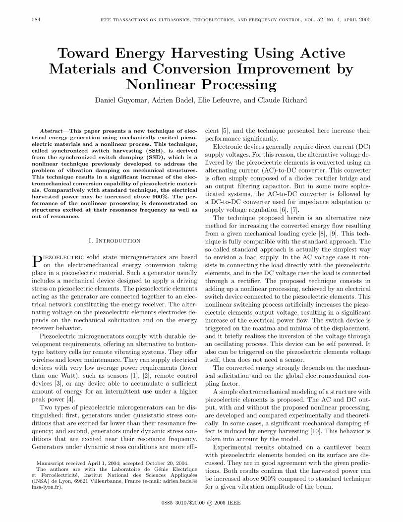
Fig. 14. Maximum harvested power for each technique versus thesquared coupling coefficient (α = 0.0035 N/V, KE = 22000 Nm−1,M = 444 g, C0 = 55.8 nF, C = 0.218 Nm−1s−1, QI = 2.6, Fm =0.1 N).
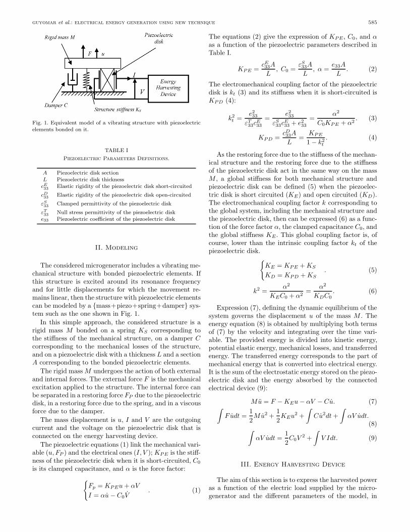
Fig. 15. Experimental setup.
requires less piezoelectric material for a given harvestedpower. For example, for the SSHI DC technique, only halfof the piezoelectric elements are needed compared to thestandard DC technique to harvest 75% of the maximumharvestable power Plim.
The curves plotted here are obtained with an inversionquality factor QI equal to 2.6, but with a greater factor,the benefit in material quantity is much increased.
V. Experimental Validation
A. Experimental Setup
The experimental test structure is a cantilever beamclamped at one end in a rigid structure, as shown inFig. 15. The beam vibrations are driven with an elec-tromagnet that generates a periodic force. The piezoelec-tric ceramic inserts are bonded on the beam close to theclamped end where the bending radius is a minimum forthe first flexural mode.
TABLE IIIExperimental Measurements.
f0 Short circuit resonance frequencyf1 Open circuit resonance frequencyξ Open circuit damping coefficientγ Piezo open circuit voltage to the beam free-end
displacement ratioC0 Clamped capacitance of the piezoelectric
elements
The electromechanical coupling factor of the globalstructure can be tuned to modify the number of piezo-electric inserts connected in parallel with the energy har-vesting device; 68 piezoelectric inserts have been bondedon the beam so that the global squared coupling factork2 could vary between 0.1% and 1%. The poling directionof the piezoelectric inserts is perpendicular to the plate,and it is the lateral coupling k31 which mainly drives thepiezoelectric response. It can be noticed that the globalcoupling factor is far lower than the intrinsic coupling fac-tor of the piezoelectric inserts (in our case k2
31 ≈ 10%).The measurement of the cantilever free-end displacementis obtained with an inductive proximity sensor.
B. Model Identification
The considered piezoelectric structure is more complexthan the simple resonator described in Section II. The var-ious parameters cannot be obtained simply from the prop-erties of the piezoelectric inserts. However, the structurepresents all the features of a piezoelectric electromechani-cal device as defined in Section II. Therefore, its propertiescan be identified using experimental measurements definedin Table III and equation (44). The identified model thencorresponds to the actual setup around the considered res-onance frequency that corresponds, in this case, to the firstflexural mode:
α = γC0, KE = αγf20
f21 − f2
0, M =
KE
4π2f20
, C = 4πξMf1.(44)
Numerical data corresponding to the experimentalsetup when all piezoelectric inserts are connected are sum-marized in Table IV.
C. Experimental Results and Discussion
1. Cantilever Beam Driven Out of Resonance: Thedriving force generated by the electromagnet is, in thiscase, tuned out of resonance. The displacement amplitudeis almost independent of the supplied load R and the en-ergy harvesting circuit.
A quarter of the piezoelectric elements are connected tothe energy harvesting device. The experimental inversionquality factor QI is 5.6. The driving force amplitude istuned so that the displacement amplitude of the beam freeend um is 0.4 mm. Experimental results and theoretical

guyomar et al.: electrical energy generation using new technique 593
TABLE IVMeasurements and Model Parameters When All Inserts are
Connected.
f0 60,18 Hzf1 60,46 Hzξ 0.00096γ 60000 V/mC0 74,3 nFα 0,0045 N/Vk2 0,0092KE 28700 Nm−1
M 200 gC 0,146 Nm−1s−1
Fig. 16. Harvested power versus the resistive load. Theoretical andexperimental comparison out of resonance (α = 0.0011 N/V, KE =28900 Nm−1, M = 200 g, C0 = 19 nF, QI = 5.6, um = 0.4 mm).
predictions using (13), (21), (31), and (37) are plotted inFig. 16 and exhibit a very good overall agreement.
According to the model, the ratio of the maximum har-vested power for the nonlinear technique to the maximumharvested power for the standard technique depends onlyon the inversion quality factor QI and is independent onthe number of piezoelectric elements connected. Practi-cally, a decrease of QI is experimentally observed whenthe number of connected piezoelectric elements decreases.
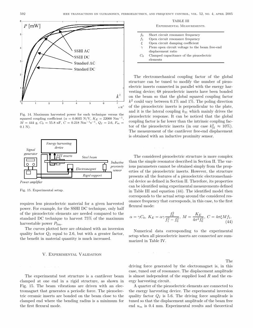
2. Cantilever Beam Driven at Resonance: The can-tilever beam in this second case is driven at the first flex-ural bending mode frequency. In these conditions, the dis-placement amplitude is very sensitive to any damping ef-fect related to a modified energy balance. Therefore, itstrongly depends on the connected load R and on the con-sidered energy harvesting strategy. The harvested poweris measured for each technique as a function of the re-sistive load R when all the piezo inserts are connected(k2 = 0.0092), when a quarter of the inserts are connected(k2 = 0.0024), when 7.3% of the inserts are connected(k2 = 0.00072), and when only 2.9% of the inserts are
Fig. 17. Normalized harvested power versus the resistive load. Theo-retical and experimental comparison for the beam excited at its res-onance with the standard technique DC. When 100% of the insertsare connected, α = 0.0045 N/V, KE = 28700 Nm−1, M = 200 g,C0 = 74.3 nF, and C = 0.146 Nm−1s−1.
connected (k2 = 0.00027). The frequency of the excitingforce must be tuned for each measurement because theresonance frequency of the structure is affected by the re-sistive load.
The inversion quality factor also is determined experi-mentally and is not constant. According to previous com-ment, it is an increasing function of the amount of con-nected piezoelements. The clamped capacitance C0 is alsoan increasing function of the area of connected piezoele-ments, and, for few connected elements, the switching de-vice parasitic capacitance becomes no more negligible com-pared to C0, which induces a decrease of the inversionquality factor. The inversion quality factor QI , therefore,is globally decreasing with the electromechanical couplingfactor.
Further work will consist of improving the electronicswitching device in order to reduce this parasitic capaci-tance problem.
Experimental results and theoretical predictions areplotted for the standard DC technique and for the non-linear DC technique, respectively, in Figs. 17 and 18. TheDC supplies are more representative of final applicationsthan the AC ones, but the AC theoretical prediction alsoappears to be in good agreement with the experimentalresults.
VI. Conclusions
The recent decrease of the power supply requirementsof many electronic devices, consequence of the numerousportable system developments made in the last decade, hasspurred a real interest in ambient energy harvesting sys-tems. This kind of portable generator might be includedin a wireless system in which it could totally replace bat-
594 ieee transactions on ultrasonics, ferroelectrics, and frequency control, vol. 52, no. 4, april 2005
Fig. 18. Normalized harvested power versus the resistive load. Theo-retical and experimental comparison for the beam excited at its res-onance with the nonlinear technique DC. When 100% of the insertsare connected, α = 0.0045 N/V, KE = 28700 Nm−1, M = 200 g,C0 = 74.3 nF, and C = 0.146 Nm−1s−1.
teries. In this field, electromechanical systems based onpiezoelectricity are of main interest. They are solid state,do not require any maintenance, and are more robust andcompact than electromagnetic generators because they donot require any rotating or translating parts.
However, the performance of a piezoelectric microgen-erator strongly depends on the electromechanical couplingthat is related in particular to the piezoelectric materialproperties and quantity. The nonlinear SSHI process pre-sented in this paper allows one to strongly enhance theenergy-harvesting performance of a given piezoelectric sys-tem. It is particularly well adapted to resonant structureswith a weak coupling or to structures driven out of res-onance. In these cases, for which the induced damping isvery low, the proposed SSHI technique exhibits an out-put power increase by over 900% compared to the samepiezoelectric system with a standard harvesting circuit.
With structures driven at the resonance frequency, itis shown that, for any energy harvesting technique, theharvested power tends to the same limit for an increas-ing electromechanical coupling, and this limit is mainlyaffected by the mechanical losses of the structure. Thisis due in particular to the strong damping effect of theSSHI technique, which for a given excitation limits the vi-bration amplitude. However, for a power lower than thislimit, the SSHI technique strongly reduces the requiredquantity of piezoelectric material comparatively to stan-dard systems, which corresponds in a drastic increase ofthe global efficiency. The SSHI technique allows the samepower enhancement that increasing the global electrome-chanical coupling associated with the standard technique.It offers a very interesting compromise between harvestedpower and piezoelectric material quantity. Therefore, fora given power requirement, the global cost of the system,
mainly due to the piezoelectric device, is significantly re-duced.
A key factor of the SSHI performance is the qualityfactor QI of the nonlinear processing circuit. The over-all power and efficiency gain is almost proportional to QI .Current work aims at precisely establishing the experimen-tal limit for this parameter, as well as defining the optimalswitch sequence for given transducer and mechanical exci-tation configuration.
Toward actual energy harvesting systems, a self-powered version of the electronic nonlinear processing cir-cuit has been successfully developed. Its electrical own con-sumption is lower than 5% of the harvested power.
References
[1] N. Elvin, A. Elvin, and M. Spector, “A mechanical strain energysensor,” Smart Mater. Struct., vol. 10, pp. 293–299, 2001.
[2] S. Horwitz, A. Kasyap, F. Liu, D. Johnson, T. Nishida, K. Ngo,M. Sheplak, and L. Cattafesta, “Technology development forself-powered sensors,” presented at 1st Flow Control Conference,June 24–26, 2002, St. Louis, MO.
[3] S. Roundy, B. Otis, Y.-H. Chee, J. Rabaey, and P. K. Wright,“A 1.9 GHz transmit beacon using environmentally scavengedenergy,” presented at Int. Symp. Low Power Electron. Design,Aug. 25–27, 2003, Seoul, South Korea.
[4] N. Shenck and J. A. Paradiso, “Energy scavenging with shoe-mounted piezoelectrics,” IEEE Micro., vol. 21, pp. 30–42, May–June 2001.
[5] C. Keawboonchuay and T. G. Engel, “Electrical power genera-tion characteristics of piezoelectric generator under quasi staticand dynamic stress condition,” IEEE Trans. Ultrason., Ferro-elect., Freq. Contr., vol. 50, no. 10, pp. 1377–1382, Oct. 2003.
[6] G. Ottman, H. Hofmann, A. Bhatt, and G. Lesieutre, “Adaptivepiezoelectric energy harvesting circuit for wireless remote powersupply,” IEEE Trans. Power Electron., vol. 17, no. 5, pp. 669–676, Sep. 2002.
[7] G. Ottman, H. Hofmann, A. Bhatt, and G. Lesieutre, “Opti-mized piezoelectric energy harvesting circuit using step-downconverter in discontinuous conduction mode,” IEEE Trans.Power Electron., vol. 18, no. 2, pp. 1988–1994, Mar. 2003.
[8] C. Richard, D. Guyomar, D. Audigier, and G. Ching, “Semipassive damping using continuous switching of a piezoelectricdevice,” presented at Proc. SPIE Smart Struct. Mater. Conf.,Passive Damping and Isolation, vol. 3672, San Diego, 1999, pp.104–111.
[9] C. Richard, D. Guyomar, D. Audigier, and H. Bassaler, “En-hanced semi passive damping using continuous switching ofa piezoelectric device on an inductor,” in Proc. SPIE SmartStruct. Mater. Conf., Passive Damping and Isolation, 2000, pp.288–299.
[10] G. A. Lesieutre, G. K. Ottman, and H. F. Hofmann, “Dampingas a result of piezoelectric energy harvesting,” J. Sound Vib.,vol. 269, pp. 991–1001, Jan. 22, 2004.
Daniel Guyomar received a degree inphysics from Amiens University, Amiens,France, an engineering and a Doctor-engineerdegree in acoustics from Compiegne Univer-sity, Compiegne, France, and a Ph.D. degreein physics from Paris VII University, Paris,France.
In 1982–1983 he worked as a research as-sociate in fluid dynamics at the Universityof Southern California (USC), Los Angeles.He was a National Research Council Awardee(1983–1984) detached at the Monterey Naval

guyomar et al.: electrical energy generation using new technique 595
Postgraduate School, CA, to develop transient wave propagationmodeling. He was hired in 1984 by Schlumberger to lead severalprojects dealing with borehole imaging, then he moved to ThomsonSubmarine activities in 1987 to manage the research activities in thefield of underwater acoustics. In 1992, Dr. Guyomar cocreated theTechsonic Company, which is involved in research, development, andproduction of piezoelectric and ultrasonic devices. He is presently afull-time University Professor at Institut National des Sciences Ap-pliquees (INSA) de Lyon, Lyon, France, where he manages the Lab-oratoire de Genie Electrique et Ferroelectricite and is consultant forseveral companies.
His present research interests are in the field of piezo-materialcharacterization, piezo-actuators, acoustics, power ultrasonics, vibra-tion control, and energy harvesting.
Adrien Badel was born in France in 1979.He graduated from Institut National des Sci-ences Appliquees (INSA) de Lyon, Lyon,France, in electrical engineering in 2002 withan M.S. degree, and is currently working to-ward the Ph.D. degree in mechanic and ma-terials at the Laboratoire de Genie Electriqueet Ferroelectricite of INSA de Lyon, Lyon,France.
His main field of interest focuses on nonlin-ear switched piezo devices for vibration damp-ing and energy harvesting.
Elie Lefeuvre was born in France on Novem-ber 13, 1971. He received the B.S. and M.S.degrees in electrical engineering, respectively,from Paris-XI University, Paris, France, in1994 and from Institut National Polytech-nique de Toulouse, Toulouse, France, in 1996.He prepared his Ph.D. degree at Laval Uni-versity of Quebec, Quebec, Canada and at theInstitut National Polytechnique de Toulouse,France; he received the diploma from bothuniversities in 2001. He became an assistantprofessor at Institut National des Sciences Ap-
pliquees (INSA) de Lyon, Lyon, France, in 2002 and joined the Lab-oratoire de Genie Electrique et Ferroelectricite.
His current research activities include energy reclamation, vibra-tion absorption, and noise reduction.
Claude Richard was born in 1965. He grad-uated from Institut National des Sciences Ap-pliquees (INSA) de Lyon, Lyon, France, inelectrical engineering in 1988 and obtainedhis Ph.D. degree in acoustics from INSA in1992 for a study on piezoelectric compositehydrophones. After a postdoctoral study on1.3 piezocomposite materials at the Underwa-ter Sound Reference Detachment of the NavalResearch Laboratory (NRL-USRD) Orlando,FL, in 1993, he got a position at INSA wherehe worked on the applications of piezoelectric
ceramics since 1994. He is currently a professor of electrical engineer-ing at INSA where he manages the Electroactive Systems Team ofthe Laboratoire de Genie Electrique et Ferroelectricite.
His research interests include nonlinear switched piezo devicesfor vibration damping and energy harvesting, 1-3 piezocomposites(dice and fill and piezo fiber composite types), power applications ofpiezoelectrics, and material characterization.