tow ards a reference-model (rm-ios) - tu berlin · spektiven basierende modell-struktur zu...
TRANSCRIPT

Towards A Reference-ModelFor Interaction Oriented Systems
(RM-IOS)
vorgelegt von
Diplom-Informatiker
Malte Philipp Armbruster
von der Fakultat IV - Elektrotechnik und Informatikder Technischen Universitat Berlin
zur Erlangung des akademischen Grades
Doktor der Ingenieurwissenschaften
– Dr.-Ing. –
genehmigte Dissertation
Promotionsausschuss
Vorsitzender: Prof. Dr. Uwe Nestmann
1. Gutachter: Prof. Dr. Bernd Mahr2. Gutachter: Prof. Dr. Klaus Robering3. Gutachter: Prof. Dr. Manfred Thuring
Tag der wissenschaftlichen Aussprache:
28. Januar 2011
———–
D83
Berlin 2011


Abstract
One of the latest and most significant challenges in the domain of software de-velopment is the successful realization of good usability of the systems generatedby this domain. Given the results of conducted surveys regarding the economicalcosts caused by a lack of software system’s user friendliness this trend is easilycomprehensible and the inevitable consequence. However, the prevalent modelsin the domain of software engineering do not sufficiently reflect the aspects ofgood usability. Thus it is often not possible to include the knowledge and exper-tise offered by usability experts and designers into the development process ofsoftware systems.
To rise to that challenge this thesis proposes the structure and essential contentfor a reference model for interaction oriented systems, in an attempt to offera fundamental, conceptual basis for an encompassing, interdisciplinary model inthe domain of software development for human-computer-interaction.
One of the main challenges regarding the construction of that model is beingposed by the systemic character of good usability, which is prohibitive of a purelyreductionist approach. Rather, during the conceptual work of the constructionof the model concepts must be accessed which have proven to be capable toolsin the context of systemic modeling. One of these is the concept of a multipleperspective based inspection of a system, which is being reflected in the structureof the model brought forward in this thesis.
The development process of this model follows a rational and analytical approachand is being anchored in the guidelines, experiences, and suggestions of acknowl-edged experts in the field of usability, to finally construct a model structure basedon three perspectives. This then enables the independent description of a sys-tem from the functionality, interaction, and design perspective, thus preparingthe ground for the necessary, interdisciplinary dialog. To secure a solid foundationfor the model introduced in this thesis, the Reference Model of Open DistributedProcessing (RM-ODP) is being drawn upon.
The practical relevance of the Reference Model for Interaction Oriented Systems(RM-IOS) is then being verified during the conduction of a case study whichserves as a proof of concept of the goals formulated in the hypothesis.
i

ii

Kurzfassung
Eine der jungsten und bedeutsamsten Herausforderungen in der Domane der Soft-ware Entwicklung ist die erfolgreiche Umsetzung von Benutzerfreundlichkeit dervon ihr hervorgebrachten Systeme. Angesichts der Ergebnisse von durchgefuhrtenStudien bezuglich der durch mangelnde Benutzerfreundlichkeit verursachten wirt-schaftlichen Kosten ist dieser Trend eine leicht nachvollziehbare und unausweich-liche Konsequenz. Doch die gangigen Modelle der Domane der Software Entwick-lung reflektieren die Aspekte der Benutzerfreundlichkeit noch nicht ausreichend.Dadurch ist es haufig nicht moglich, das Wissen, welches Usability Experten undDesigner zur Verfugung stellen, entsprechend in die Entwicklungsprozesse ein-fließen zu lassen.
Um sich der Herausforderung dieser Situation zu stellen, wird in dieser Arbeit dieStruktur und inhaltliche Basis eines Referenz-Modells fur interaktionsorientierteSysteme vorgestellt, in dem Versuch, eine fundamentale, konzeptuelle Grund-lage fur ein umfassendes, interdisziplinares Modell in der Domane der SoftwareEntwicklung fur Mensch-Computer-Interaktion zu bereiten.
Eine der Hauptschwierigkeiten hierbei stellt sich in dem systemischen Charakterguter Benutzbarkeit dar, welcher einen rein reduktionistischen Ansatz ausschließt.Vielmehr muss bei der Modellierungsarbeit auf Konzepte zuruckgegriffen werden,die sich im Kontext systemischer Modellierung bewahrt haben. Eines davon istdas Konzept der multiplen perspektivischen Betrachtung eines Systems, welchessich in der Struktur des hier vorgestellten Modells widerspiegelt.
Die Entwicklungsarbeit fur die Erstellung dieses Modells folgt einem rationalen,analytischen Verfahren und wird in den Richtwerten, Erfahrungen und Ratschla-gen anerkannter Usability-Experten verankert, um schließlich eine auf drei Per-spektiven basierende Modell-Struktur zu konstruieren. Diese ermoglicht danneine unabhangige Beschreibung eines Systems aus der funktionalen, interaktivenund gestalterischen Perspektive und offnet somit den Raum fur den notwendigeninterdisziplinaren Dialog. Als Basis wird hierfur das Reference Model of OpenDistributed Processing (RM-ODP) herangezogen, wodurch eine solide Grundlagefur das Modell gesichert wird.
Die praktische Relevanz des hier vorgestellten Reference Model for InteractionOriented Systems (RM-IOS) wird in einer im Rahmen dieser Arbeit durchgefuhrtenFallstudie verifiziert, welche als Nachweis der erfolgreichen Umsetzung der in derHypothese dieser Arbeit formulierten Ziele dient.
iii

iv

Contents
List of Figures xi
List of Tables xiii
List of Abbreviations xv
1 Introduction 1
1.1 Problem statement . . . . . . . . . . . . . . . . . . . . . . . . . 2
1.2 Hypothesis . . . . . . . . . . . . . . . . . . . . . . . . . . . . . 3
1.3 Approach . . . . . . . . . . . . . . . . . . . . . . . . . . . . . . 4
1.4 Structure of this Thesis . . . . . . . . . . . . . . . . . . . . . . 5
2 Preparing Thoughts 9
2.1 Model . . . . . . . . . . . . . . . . . . . . . . . . . . . . . . . 9
2.1.1 The “Model” term . . . . . . . . . . . . . . . . . . . . . 9
2.2 System . . . . . . . . . . . . . . . . . . . . . . . . . . . . . . . 12
2.2.1 Software Systems . . . . . . . . . . . . . . . . . . . . . 15
2.3 Separation of Concern . . . . . . . . . . . . . . . . . . . . . . . 17
2.3.1 Division of Responsibility and Division of Labor . . . . . . 17
2.3.2 Separation of Concern in Software Systems . . . . . . . . 19
3 State of the Art 25
3.1 Reference Models in UI Development . . . . . . . . . . . . . . . 26
3.2 Models in the Domain of Software Engineering for the User In-terface Development . . . . . . . . . . . . . . . . . . . . . . . 27
3.3 Models and Methodologies for the MDD Approach in UI Devel-opment . . . . . . . . . . . . . . . . . . . . . . . . . . . . . . . 28
3.3.1 Model View Controller . . . . . . . . . . . . . . . . . . . 29
v

3.3.2 Unified Modeling Language . . . . . . . . . . . . . . . . 32
3.3.3 RM-ODP . . . . . . . . . . . . . . . . . . . . . . . . . . 35
3.3.4 UsiXML . . . . . . . . . . . . . . . . . . . . . . . . . . 37
3.3.5 UMLi . . . . . . . . . . . . . . . . . . . . . . . . . . . . 38
3.3.6 GOMS . . . . . . . . . . . . . . . . . . . . . . . . . . . 38
3.4 Dialog Models . . . . . . . . . . . . . . . . . . . . . . . . . . . 39
3.4.1 Backus-Naur Form (BNF) grammars . . . . . . . . . . . 39
3.4.2 State Transition Diagrams . . . . . . . . . . . . . . . . . 40
3.4.3 Statecharts . . . . . . . . . . . . . . . . . . . . . . . . . 40
3.4.4 Petri Nets . . . . . . . . . . . . . . . . . . . . . . . . . 41
3.5 ISO Standards Relevant to UI Development . . . . . . . . . . . . 41
3.5.1 ISO 13407 . . . . . . . . . . . . . . . . . . . . . . . . . 41
3.5.2 ISO 9241 . . . . . . . . . . . . . . . . . . . . . . . . . . 42
3.5.3 ISO 9126 . . . . . . . . . . . . . . . . . . . . . . . . . . 42
3.5.4 ISO 25000 . . . . . . . . . . . . . . . . . . . . . . . . . 43
3.6 Conclusion . . . . . . . . . . . . . . . . . . . . . . . . . . . . . 44
4 Development and Overview of the RM-IOS 45
4.1 Motivation . . . . . . . . . . . . . . . . . . . . . . . . . . . . . 46
4.2 Development of the Model . . . . . . . . . . . . . . . . . . . . . 47
4.2.1 Towards a Reference Model for Interaction Oriented Systems 48
Shneiderman’s Eight Golden Rules of Interface Design . . 48
Collecting Relevant Aspects . . . . . . . . . . . . . . . . 51
Structuring Relevant Aspects . . . . . . . . . . . . . . . 52
Grouping Relevant Aspects . . . . . . . . . . . . . . . . 55
Selecting Relevant Aspects . . . . . . . . . . . . . . . . 56
4.3 RM-IOS - Description . . . . . . . . . . . . . . . . . . . . . . . 60
4.3.1 RM-IOS - Foundation . . . . . . . . . . . . . . . . . . . 60
4.3.2 RM-IOS - Functionality . . . . . . . . . . . . . . . . . . 62
4.3.3 RM-IOS - Interaction . . . . . . . . . . . . . . . . . . . 63
4.3.4 RM-IOS - Style . . . . . . . . . . . . . . . . . . . . . . 64
4.3.5 Coverage of the RM-IOS . . . . . . . . . . . . . . . . . . 64
4.4 RM-IOS - Six Questions for a Model . . . . . . . . . . . . . . . 67
4.4.1 Questions for a model . . . . . . . . . . . . . . . . . . . 67
What is RM-IOS a model of? . . . . . . . . . . . . . . . 68
What is RM-IOS a model for? . . . . . . . . . . . . . . . 68
vi

Who is RM-IOS for? . . . . . . . . . . . . . . . . . . . . 69
Whom is RM-IOS from? . . . . . . . . . . . . . . . . . . 69
What is RM-IOS’ problem domain? . . . . . . . . . . . . 69
What is RM-IOS’ solution domain? . . . . . . . . . . . . 70
5 Reference Model for Interaction Oriented Systems 71
5.1 RM-IOS . . . . . . . . . . . . . . . . . . . . . . . . . . . . . . 71
5.2 Foundation . . . . . . . . . . . . . . . . . . . . . . . . . . . . . 71
5.3 Functionality Viewpoint . . . . . . . . . . . . . . . . . . . . . . 82
5.4 Interaction Viewpoint . . . . . . . . . . . . . . . . . . . . . . . 85
5.5 Style Viewpoint . . . . . . . . . . . . . . . . . . . . . . . . . . 93
5.6 Structural UML Class Diagrams of RM-IOS . . . . . . . . . . . . 104
5.7 Conclusion . . . . . . . . . . . . . . . . . . . . . . . . . . . . . 109
6 Case Study 111
6.1 Case Study . . . . . . . . . . . . . . . . . . . . . . . . . . . . . 111
6.2 Case Study - Data Collection . . . . . . . . . . . . . . . . . . . 114
6.2.1 Technical Data . . . . . . . . . . . . . . . . . . . . . . . 115
6.2.2 Case Study Method . . . . . . . . . . . . . . . . . . . . 115
This Case Study’s Approach . . . . . . . . . . . . . . . . 116
RM-IOS Elements Used From Each Perspective . . . . . . 117
Collection of the Data . . . . . . . . . . . . . . . . . . . 118
6.2.3 Data Types in the Case Study . . . . . . . . . . . . . . . 120
Trigger . . . . . . . . . . . . . . . . . . . . . . . . . . . 121
String . . . . . . . . . . . . . . . . . . . . . . . . . . . 121
Expressive Text . . . . . . . . . . . . . . . . . . . . . . 121
Contact . . . . . . . . . . . . . . . . . . . . . . . . . . 121
Date . . . . . . . . . . . . . . . . . . . . . . . . . . . . 122
Graphic . . . . . . . . . . . . . . . . . . . . . . . . . . . 122
Mark . . . . . . . . . . . . . . . . . . . . . . . . . . . . 122
6.3 Pre . . . . . . . . . . . . . . . . . . . . . . . . . . . . . . . . . 123
6.3.1 Functionality . . . . . . . . . . . . . . . . . . . . . . . . 123
Input . . . . . . . . . . . . . . . . . . . . . . . . . . . . 123
Output . . . . . . . . . . . . . . . . . . . . . . . . . . . 123
6.3.2 Interaction . . . . . . . . . . . . . . . . . . . . . . . . . 124
Input . . . . . . . . . . . . . . . . . . . . . . . . . . . . 124
vii

Output . . . . . . . . . . . . . . . . . . . . . . . . . . . 124
6.3.3 Style . . . . . . . . . . . . . . . . . . . . . . . . . . . . 125
Input . . . . . . . . . . . . . . . . . . . . . . . . . . . . 125
Output . . . . . . . . . . . . . . . . . . . . . . . . . . . 127
6.4 iPhone . . . . . . . . . . . . . . . . . . . . . . . . . . . . . . . 128
6.4.1 Functionality . . . . . . . . . . . . . . . . . . . . . . . . 128
Input . . . . . . . . . . . . . . . . . . . . . . . . . . . . 128
Output . . . . . . . . . . . . . . . . . . . . . . . . . . . 128
6.4.2 Interaction . . . . . . . . . . . . . . . . . . . . . . . . . 129
Input . . . . . . . . . . . . . . . . . . . . . . . . . . . . 129
Output . . . . . . . . . . . . . . . . . . . . . . . . . . . 129
6.4.3 Style . . . . . . . . . . . . . . . . . . . . . . . . . . . . 131
Input . . . . . . . . . . . . . . . . . . . . . . . . . . . . 131
Output . . . . . . . . . . . . . . . . . . . . . . . . . . . 131
6.5 Comparison . . . . . . . . . . . . . . . . . . . . . . . . . . . . . 132
6.5.1 Functionality . . . . . . . . . . . . . . . . . . . . . . . . 132
Input . . . . . . . . . . . . . . . . . . . . . . . . . . . . 132
Output . . . . . . . . . . . . . . . . . . . . . . . . . . . 133
6.5.2 Interaction . . . . . . . . . . . . . . . . . . . . . . . . . 134
Input . . . . . . . . . . . . . . . . . . . . . . . . . . . . 134
Output . . . . . . . . . . . . . . . . . . . . . . . . . . . 135
6.5.3 Style . . . . . . . . . . . . . . . . . . . . . . . . . . . . 135
6.5.4 Input . . . . . . . . . . . . . . . . . . . . . . . . . . . . 135
Output . . . . . . . . . . . . . . . . . . . . . . . . . . . 136
6.6 Conclusion . . . . . . . . . . . . . . . . . . . . . . . . . . . . . 137
6.6.1 Feedback for the Reference Model for Interaction OrientedSystems . . . . . . . . . . . . . . . . . . . . . . . . . . 138
Scene . . . . . . . . . . . . . . . . . . . . . . . . . . . . 138
Mode of Operation and Mode of Presentation . . . . . . 139
Equilibrioceptic Interaction . . . . . . . . . . . . . . . . 139
Minimum Value and Maximum Value . . . . . . . . . . . 140
6.7 Evaluation of the Case Study . . . . . . . . . . . . . . . . . . . 140
6.7.1 Evaluation in Regard to the Inspected Scenes . . . . . . . 141
Comparison of the Pre’s and iPhone’s Scene . . . . . . . 141
6.7.2 Evaluation in Regard to the RM-IOS . . . . . . . . . . . 143
Policy of Separation of Concern . . . . . . . . . . . . . . 143
viii

Provision of Methodological Ground . . . . . . . . . . . . 144
7 Conclusion 147
7.1 Summary of Contributions . . . . . . . . . . . . . . . . . . . . . 147
7.1.1 Contributions - From the Analytical Perspective . . . . . 147
Description . . . . . . . . . . . . . . . . . . . . . . . . . 148
Comparison . . . . . . . . . . . . . . . . . . . . . . . . 148
Verification . . . . . . . . . . . . . . . . . . . . . . . . . 148
Evaluation . . . . . . . . . . . . . . . . . . . . . . . . . 148
7.1.2 Contributions - From the Synthetical Perspective . . . . . 149
Specification . . . . . . . . . . . . . . . . . . . . . . . . 149
7.1.3 Modeling . . . . . . . . . . . . . . . . . . . . . . . . . . 149
7.1.4 Internal Validation . . . . . . . . . . . . . . . . . . . . . 150
7.1.5 External Validation . . . . . . . . . . . . . . . . . . . . . 151
7.2 Future Work in Prospect . . . . . . . . . . . . . . . . . . . . . . 152
7.3 Scientific Challenges . . . . . . . . . . . . . . . . . . . . . . . . 154
A Appendix 157
A.1 Shneiderman’s Eight Golden Rules Of Interface Design . . . . . . 157
Bibliography 194
ix

x

List of Figures
3.1 Model-View-Controller Concept . . . . . . . . . . . . . . . . . . 30
3.2 The fourteen diagram types of UML 2.3 represented by a UMLclass diagram. . . . . . . . . . . . . . . . . . . . . . . . . . . . 33
3.3 Example of Backus-Naur-Form . . . . . . . . . . . . . . . . . . 39
4.1 Aspects of a contemporary IOS . . . . . . . . . . . . . . . . . . 53
4.2 Aspects of a contemporary IOS and their relations . . . . . . . . 55
4.3 Aspects of a contemporary IOS grouped by colors - 1 . . . . . . 57
4.4 Aspects of a contemporary IOS grouped by colors - 2 . . . . . . 58
4.5 RM-IOS Architecture . . . . . . . . . . . . . . . . . . . . . . . 65
5.1 RM-IOS Foundation - UML Class Diagram . . . . . . . . . . . . 105
5.2 RM-IOS Functionality - UML Class Diagram . . . . . . . . . . . 106
5.3 RM-IOS Interaction - UML Class Diagram . . . . . . . . . . . . 107
5.4 RM-IOS Style - UML Class Diagram . . . . . . . . . . . . . . . 108
6.1 Screenshots of the Pre and iPhone for the Case Study . . . . . . 116
6.2 Structure of the Data Collected in the Case Study . . . . . . . . 119
xi

xii

List of Tables
4.1 RM-IOS’ Perspectives in Galitz’ Approach to UI Development . . 66
6.1 Case Study - Technical Data . . . . . . . . . . . . . . . . . . . . 115
6.2 Pre - Data Input and Input Type (Functionality Input) . . . . . . 123
6.3 Pre - Data Output and Output Type (Functionality Output) . . . 124
6.4 Pre - Modality and Mode of Operation (Interaction Input) . . . . 125
6.5 Pre - Modality and Mode of Presentation (Interaction Output) . 126
6.6 Pre (Style Input) . . . . . . . . . . . . . . . . . . . . . . . . . . 126
6.7 Pre (Style Output) . . . . . . . . . . . . . . . . . . . . . . . . . 127
6.8 iPhone - Data Input and Input Type (Functionality Input) . . . . 128
6.9 iPhone - Data Output and Output Type (Functionality Output) . 129
6.10 iPhone - Modality and Mode of Operation (Interaction Input) . . 130
6.11 iPhone - Modality and Mode of Presentation (Interaction Output) 130
6.12 iPhone (Style Input) . . . . . . . . . . . . . . . . . . . . . . . . 131
6.13 iPhone (Style Output) . . . . . . . . . . . . . . . . . . . . . . . 132
6.14 Pre - iPhone (Functionality Input) . . . . . . . . . . . . . . . . . 133
6.15 Pre - iPhone (Functionality Output) . . . . . . . . . . . . . . . . 134
6.16 Pre - iPhone (Interaction Input) . . . . . . . . . . . . . . . . . . 135
6.17 Pre - iPhone (Interaction Output) . . . . . . . . . . . . . . . . . 136
6.18 Pre - iPhone (Style Input) . . . . . . . . . . . . . . . . . . . . . 137
6.19 Pre - iPhone (Style Output) . . . . . . . . . . . . . . . . . . . . 138
xiii

xiv

List of Abbreviations
EHCI Engineering for Human-Computer Interaction
GUI Graphical User Interface
HCI Human Computer Interaction
MB-UIDE Model-Based User Interface Development Environment
MDD Model Driven Development
OMG Object Management Group
RM-IOS Reference Model for Interaction Oriented Systems
RM-ODP Reference Model of Open Distributed Processing
UI User Interface
UID User Interface Development
UIE User Interface Engineering
UML Unified Modeling Language
UsiXML USer Interface eXtensible Markup Language
VUI Voice User Interface
WYSIWYG “What You See Is What You Get”
XML eXtensible Markup Language
xv

xvi

“Because every person knows what he likes,every person thinks he is an expert on user interfaces.”
Paul Heckel, 1982
xvii

xviii

Chapter 1
Introduction
In the early days of software, when calculations were done based on algorithmsread from punchcards, the biggest concern was the correctness of the software.Scientists firmly rooted in mathematical backgrounds were, both, programmerand user in one person and dove into the pool of new found, immense calculatingpower provided by the computers. As with all ground breaking technologies, hereas well the aspect of “usability” - let alone “intuitiveness” - was of absolutelyminimal concern. Again, the main challenge was lying in the software deliveringcorrect results at all. That situation has evolved and changed dramatically, astoday the calculating power of modern home-computers often exceed the actualdemand of the software running on them and the total user base comprisesall age groups, all professions, all educational backgrounds, all aspects fromcasual entertainment to professional applications, and has penetrated almost allaspects of our daily lives. And no longer is the programmer the only user ofits own system, quite the opposite is true: very rarely is the developer also thedesignated user of the software and hardly any end-user implements their ownsoftware.
As a consequence of this situation so radically different from the early days ofcomputing, the aspect of usability has already become one of the main challengesand often finds itself to be the key criterion in modern applications or softwarecontrolled devices. The way software is being designed and developed, however,does not sufficiently reflect this new situation, effectively leaving the huge andcomplex task to deliver correctly working and - so called - intuitively usablesoftware to the “the computer scientist” or “the software engineer” to tackle.But as a task complex enough to spawn new faculties at universities falls onthe shoulders of people whose expertise lies in different fields, the result of thissituation is often unsatisfying as can be seen from products that fail on themarket - recently most often because of usability issues and complaints by the
1

Introduction CHAPTER 1
end-user about interactions too cumbersome to learn, too annoying to performfrequently, or too restricting. Looking at some of the most established conceptsand paradigms in the software development domain sheds some light on thisapparent deficit as they stem from a time where the main challenge and thus thefocus was still lying in producing correct and reliable software.
In order to rise to the challenge posed by the “as-is” situation just depicted itseems sensible to approach it from a meta level, scrutinizing software design anddevelopment as a holistic process while assuming different positions to betterunderstand the currently present discrepancies in skill and requirement from thepeople and methodologies involved in the entire process.
1.1 Problem statement
An obviously inherent side-effect of the evolution of technical systems is the in-crease in complexity of these. Software engineering as a discipline dealing with aspecial kind of technical system, namely software systems, faces the same chal-lenge of increasing complexity as a result of an increase in functional complexityand expected quality in user interaction. Examples for the latter point are thebroadening user base of software applications, the penetration of business pro-cesses by software, the daily confrontation with software in common situations.Thus the development of today’s modern software systems require well organizeddeveloping teams with appropriate and able tools, and efficient methodologies tomanage the complexity of software development projects and increase the chanceof a successful outcome [AMB+04].
It is, however, a widely acknowledged fact in the software industry that actuallyonly a minority of software projects result in a satisfying product in terms oftime taken from conception to the release of the application, staying within thedevelopment budget, or meeting the client’s expectations in terms of functionalityand usability [SP05][Cha09][RG01].
While several aspects are relevant to this problem recently especially the issue ofusability and interaction design has received increased attention from, both, thedeveloper and the client side, as some ads and slogans from large manufacturersof heavily software rooted technical devices – for example Philips’ “Sense andSimplicity” [Phi09] – also give testament to.
One fundamentally important and enabling technique in the evolution of tech-nology is the development of a well defined policy of “separation of concern”,allowing for the increasing mass of knowledge in a discipline to be distributed intodistinct sets of chunks defined by describing uniting and distinguishing attributes.
2

Introduction CHAPTER 1
This allows for specialization and levels of expertise otherwise not feasible if allcomprised in one discipline.
In software, however, a distinct difference to other traditional engineering disci-plines is the circumstance that the fundamental building blocks are not tangiblematerials but source code, thus not offering a natural separation of concern basedon subfields specialized in the handling of certain material [RS08]. But severaltechniques exist where a policy of separation of concern has been introduced intosoftware engineering with great success. Examples are the object-oriented pro-gramming (OOP) paradigm in programming and system architecture, the model-view-controller (MVC) pattern in GUI oriented programming, or the extensivereference model for open distributed processing (RM-ODP) in the developmentof open distributed systems. All these techniques have provided – over the timethey have been applied – empirical evidence that they allow for more complexsystems to be successfully developed and maintained. Yet, none of the existingpatterns regard the increasingly important aspect of usability and interactabilitywith sufficient distinction [CRC07] [SP05] [Ras07]. These three cornerstones ofthe evolution of software design and development will be discussed in regard totheir inclusion of usability aspects - or lack thereof - very briefly in chapter 2 andthen more thoroughly in 3.
1.2 Hypothesis
It is possible to develop a perspective based reference-model defining a policyof separation of concern applicable to software design and development in thesegment of interaction with the following effects:
� mirroring the separated domains of skill, knowledge, and expertise requiredto cope with the needs of successful interaction design and implementation
� covering the many aspects to be dealt with in successful interaction designand implementation
� providing methodological ground for analysis and evaluation of existinginteraction solutions
� providing the basis for proper organization of development teams for inter-action design and implementation
� it can be justified by what is known about successful interaction designand implementation endeavors.
3

Introduction CHAPTER 1
Assumptions
This hypothesis is based on two assumptions. Namely, the first assumption,that it is possible and sensible to separate the domain of software design anddevelopment into distinct sub-domains. This assumption is based on observingcomparable separations in other domains, such as engineering disciplines andconstruction workflows where measurable advantages have been reached. Basedon the established first assumption the following second assumption then is thata separation of the domain of software design and development into the sub-domains of “functionality”, “interaction”, and “style” aspects gives reason tobelieve to be meeting many of the points listed above.
1.3 Approach
In this thesis the points listed in the hypothesis (1.2) will be answered by con-structing a reference-model describing three distinct viewpoints.
Namely the viewpoint containing the concerns of the provided functionality of asoftware system, the viewpoint containing the interaction and usability concernsof a software system, and the viewpoint containing the concerns relevant toaesthetic design decisions.
The description of these three viewpoints then provide a meta-framework forconceptualizing, inspecting, and analyzing software systems while appreciatingthe different domains of skill, knowledge, and expertise that each stems from.Furthermore it acknowledges the growing importance of usability and interactionconcerns and provides the semantic lense to focus on these challenges in modernsoftware systems.
However, it has to be acknowledged, that it is - per definition - impossible toprovide empirical justification for the development of a model as just describedduring the course of a thesis. To cope with this a rational approach must befollowed in assuring that the model fulfills the points established in the hypothesis.
During the course of this thesis it will be attempted to present and justify thesetwo assumptions made in the hypothesis in a comprehensible and traceable man-ner to then apply the consequences arising from them to the domain of softwaredesign and development with the intent to describe a reference model meetingthe points listed in the hypothesis (1.2).
4

Introduction CHAPTER 1
1.4 Structure of this Thesis
Chapter 1 - Introduction
Chapter 1 provides the reader with an introduction into the domain of this thesisand presents the problem statement, the driving motivation for this thesis. Fol-lowed then by the hypothesis, and a description of the approach that was takenin order to verify the hypothesis.
Chapter 2 - Preparing Thoughts
Chapter 2 introduces the fundamental underlying concepts of this thesis, namelythe concept of a model and the concept of a system in order to prepare somecommon mental ground on which to build the rest of the thesis. The approachof this chapter is a top-down approach, i.e. the two concepts are viewed at firstfrom a general perspective and are then refined and specified to the point ofview taken by this thesis. Consequently the following chapters build on top ofthe terms and concepts identified and defined in this chapter.
Chapter 3 - State of the Art
Chapter 3 presents and discusses the current state of the art in the domain ofsoftware design and development in the field of user interface engineering. It isthe goal of this chapter to give the reader a sufficient overview of some of thecurrently applied models and methodologies in respect to the problem statementand hypothesis presented in the introduction (1.1 and 1.2). Together with theproblem statement and the hypothesis, the current state of the art provides thethird anchorpoint to identify the contribution made by this thesis.
Chapter 4 - Development and Overview of the RM-IOS
Chapter 4 lays out the analytical development process that preceded and lead tothe development of the Reference Model for Interaction Oriented Systems. Partof this chapter are furthermore summarizing descriptions of the model and theanswer to six fundamental questions any model can be asked.
Chapter 5 - Reference Model for Interaction Oriented Systems
Chapter 5 then presents the Reference Model for Interaction Oriented Systemsthat has been designed and constructed in order to answer to the challengesposed by the problem statement and substantiated by the hypothesis. It is the
5

Introduction CHAPTER 1
result of following the approach described in chapter 4. The Reference Model forInteraction Oriented Systems describes three point of views, that of the function-ality of a software (“What can a user do?”), that of the interaction between asoftware and the user (“How does a user access the functionality?”), and that ofthe style of the possible interaction (“How are the interaction possibilities beingpresented to the user?”).
Chapter 6 - Case Study
Chapter 6 demonstrates a practical application of the Reference Model for In-teraction Oriented Systems by analyzing typical activities performed with twodifferent, state of the art smartphones (the Palm Pre and the Apple iPhone).By subjecting the same activity on each different device to the same analysistechnique based on the Reference Model for Interaction Oriented Systems a firstimpression is being offered to the analytical value of the Reference Model forInteraction Oriented Systems.
While it is sensible to assume that the Reference Model for Interaction OrientedSystems could also be of value to the synthesis of software a demonstration ofsuch synthesis will not be part of this thesis for several reasons, mainly the fol-lowing two: Firstly, any software synthesis beyond the most trivial level requiressignificant time and resources and secondly, the synthesis of software, especiallythe synthesis in accordance with this Reference Model for Interaction OrientedSystems would require expertise in all three areas, i.e. the area of functional-ity, interaction-design, and style-design. The combination of these two aspectsmade a case-study focusing on the synthesis value of the Reference Model forInteraction Oriented Systems impossible during the course of the writing of thisthesis.
Chapter 7 - Conclusion
Chapter 6 presents the conclusions of this thesis and the contributions made. Italso discusses the scientific outlook and offers ideas for work that could build onthe basis of this thesis.
Appendix
The Appendix contains the “Eight Golden Rules of Interface Design” by Shnei-derman as they are being referenced and included in the analytical developmentprocess of the reference model for interaction oriented system. Also the RM-ODP foundations section is placed in the appendix as the model of this thesis
6

Introduction CHAPTER 1
has been built with the RM-ODP foundation as its model basis. This allows thereader to conveniently look up the RM-ODP foundation and also preserves theversion that this thesis’ model has been built on.
7

8

Chapter 2
Preparing Thoughts
Before it is possible to think about any kind of separation of an entity, the wholeentity must be viewed and inspected with the goal to find out about its natureand characteristic attributes relevant for the kind of intended separation. Theintended separation in this thesis will be the establishing of perspectives basedon the domains of skill, knowledge, and expertise of the designers and developersinvolved in the user interface development process. Hence the whole, i.e. thedomain of software design and development in user interface development mustbe viewed and approached thusly, that the just mentioned segments becomementally visible and tangible.
In preparation of this the fundamental terms must be identified and defined asused and to be understood throughout this thesis. This chapter introduces theseterms and follows a top-down approach: providing at first a very general view ona term to then narrow down on the term, focusing on the term with the semanticlense of this thesis’ domain to finally provide a definitive description, making theterm useful to communicate the concepts needed for this thesis.
2.1 Model
2.1.1 The “Model” term
The chapter will begin with a clarification of the “model” term in order to es-tablish a common understanding of the term as it will be used throughout thisthesis and this chapter especially. Then the motivation regarding the usefulnessor even necessity of models is being presented; first from a more general point ofview, then narrowed down to why models are useful and necessary in the contextof the particular domain this model is being introduced into, namely the domainof software design and development.
9

Preparing Thoughts CHAPTER 2
Stachowiak and Mahr
The term “model” is prevalently used and heavily overloaded as discussed in greatdetail by Mahr in [Mah03]. In this article Mahr first illuminates the complex ety-mological history of the term “model” and soon concludes, that the “modelness”of a model is not something that can be found in any of the model’s attributes,but rather must be identified in the pragmatic context, in which the decision isbeing made to perceive something as a model. This is a stark distinction fromthe usually accepted definition of a model in technical domains which is basedon Stachowiak’s definition who stipulates three attributes a model must possess[Sta73]. A good translation and further inspection of this definition of a modeland its role in the model driven development can be found in Kuhne’s article“What is a Model?” [Kuh05]:
1. mapping feature - a model is based on an original
2. reduction feature - a model only reflects a (relevant) selection of the orig-inal’s properties
3. pragmatic feature - a model needs to [be] usable in place of the originalwith respect to some purpose
To locate the “modelness” of a model in either in some attributes of the modelitself or in the context of perception of whomever perceives a model as a modelis the most fundamental difference between Stachowiak’s and Mahr’s definitionof a model. Following Mahr’s argumentation in [Mah03] the following thoughtscan be extracted:
Vitruv and the Proportions
In the historic context of the model where Vitruv uses the model as a tool toexpress what he must obviously perceive as the essence of architecture, namelythe proportions and symmetry of a structure, a striking similarity can be identifiedin the use of models in today’s information technology where models are used toexpress the essence of software systems; often from several different perspectivesas the complexity of contemporary software systems demands.
In his contemplations of the model, Mahr also raises the question exactly howuseful a model (in the Vitruvian context of architecture) can be to produce beautyand lead to the realization of aesthetic ideals, when it merely contains numbersregarding the proportions of the architecture. It must then be deduced that inregard to the perceived beauty of the building the, say, color of the building wasnot nearly as important as the proportion of its elements. The details worked
10

Preparing Thoughts CHAPTER 2
into the facade of the building possibly only artistic expressions of the builder notfundamental aspects of the structure’s beauty. The essence of the ideal of beautyand aesthetic was identified in the proportions of the building and thus this isthe aspect captured and transmitted in the Vitruvian concept of the model.
And here the similarity to the nature of models and their conception and use inthe context of contemporary software development can be extended even further,as a model of a software system never contains an explicit description of, say,the actual source code to be implemented. It contains merely those aspectsperceived as being of fundamental importance to the defining characteristics ofthat particular software and its architecture. The actual source code, the way adeveloper comments the code, even the details of the algorithms implemented torealize the functionality required from the system, and aesthetic aspects whetherthe curly braces of function calls are placed on the same line of the function’sname or on the next are simply relinquished to the personal preference of thedeveloper1; much as the aspects of a building not captured in the Vitruvian modelare relinquished to the builder’s personal preference.
It can be concluded, then, that in the models provided for and by a discipline,and used by a discipline an unambiguous inference can be drawn about whatis being perceived as essential aspects to that discipline, i.e. aspects perceivedas fundamentally crucial; important enough to be included in the models ofits artifacts. Thus, inspecting the models currently prevalent in the domain ofsoftware development some insight should be gained about where the prioritiesof that discipline lie. This inspection will be done in chapter 3.
Models as a Lense of a Discipline’s Focus
Mahr continues and mentions Durer, who failed in his attempt of capturingthe beauty of the human body by merely referring to the proportions of it andsubsequently expressed this apparently disappointing realization with the words“Waß aber dy schonheit sey, daz weis jch nit.” [Win71, p. 61], which translatesinto: “but what beauty is, that I do not know”. Mahr then draws the acuteconclusion that the models used by a discipline can be a limiting factor on theperception of the discipline regarding the entities it is occupied with. Anotherparallel can be drawn to the lack of usability related aspects in the prevalentmodels used in the domain of software engineering and the lack of good usabilityin contemporary software systems; more on that, also, in chapter 3.
1This may not always be the case when large groups of developers work on the same codeand maximum legibility must be obtained. But this leads into another direction entirely.
11

Preparing Thoughts CHAPTER 2
Summarizing Thoughts on the Model
In this article Mahr formulates the concept of a model always being a model ofsomething and a model for something (a thought which Mahr then extends tothe concept of the “cargo of a model” in [Mah09], however, this continuativeconcept is not necessary for this thesis).
It can be said, that models in general are a fundamental component to a disciplineand the nature of models determines and are a mirror of the nature of thoughtsa discipline preoccupies itself with. And the discipline of information sciencerelies particularly strongly on models and their expressive power (for an in-depthdiscussion of this thought refer to Mahr’s article “Information science and thelogic of models” [Mah09]).
In accordance with Mahr’s conceptual nature of a model, the model introducedin this thesis is being defined by answering to the questions “what is this modela model of” and “what is this model a model for”. The answers to these twoquestions, along with answers to other questions that are also relevant to thismodel, will be given in section 4.4.
2.2 System
The etymological root of the word “system” is the greek word “systema“ whichin turn comprises the two greek words “syn” (together) and “histemi” (put)and thus describes a whole which consists of parts. Due to this high-level andextremely generic meaning of the word, it can be found used in almost anycontext, i.e. the “nervous system” in the medical context, the “financial system”in an economic context, the “health-care system” in the public health context,the “system of intervals” in the music-theory context, or the “computer system”in the technological context, to name just a few.
Aristotle and Metaphysics
The first recorded philosophic usage of the word can be found in Plato’s dialog“Philebus” from 360 B.C. [PlaBC] where he applies the term “system” to describe(musical) intervals and their relation to one another.
But when you have learned what sounds are high and what low, andthe number and nature of the intervals and their limits or propor-tions, and the systems compounded out of them, which our fathersdiscovered, and have handed down to us who are their descendantsunder the name of harmonies [...]
12

Preparing Thoughts CHAPTER 2
But Plato and Aristotle also apply the term “system” to describe a federationof states and within the hellenistic school of thought the Stoics make use of theterm to describe the cosmos as a physical system of the heavens and the earthand the creatures in between [Mar98]. Possibly the most well known quote aboutsystems and their special nature comes from Aristotle in his work Metaphysicswhere he states “the whole is more than the sum of its parts [Ari91]” giving wordto the concept of a system’s “emerging properties”. Then throughout historythe term system is being used ubiquitously in any context.
Descartes and Reductionism
A turning point in the thinking of and about systems was the reductionist schoolof thought, with Rene Descartes being one of its most prominent thinkers.Descartes held the belief, that a system and its properties is no more than thesum of the properties of its parts [Des37]. This was a stark contrast to thearistotelean view of a system being more than the sum of its parts.
von Bertalanffy and General Systems Theory
Returning to the aristotelean view on systems (regarding the interdependentcomplexity of its parts) it was the biologist Ludwig von Bertalanffy who laid thefoundation for the establishing of “systems theory” as a scientific discipline withhis influential book on the thinking of and about systems, which was publishedin the year 1976. The book is titled “General Systems Theory” [vB76] and in itvon Bertalanffy strives to establish a theory for thinking about and working withsystems in an abstract and general way and returns to the principle of “emergingproperties”, i.e. properties of a system that are not present in any of its partsindividually but only come to be in their systemic liaison2.
2It is interesting that the concept of an emerging property can be described particularlywell with musical intervals, which is the context from which Plato’s and Aristotle’s use of theterm “system” stems. When such an interval of two tones sounds, it is extremely difficultfor the untrained ear to identify the two sounds that produce the sound of the interval. Theindividual tones merge together to form the characteristic sound of that interval, where theindividual tones themselves become less present to the listener and the characteristic soundof the interval emerges. The characteristic sound of the interval here is an emerging propertyof the two sounds in the interval as that characteristic sound of the interval is not presentin either of the two tones by themselves but only in their combination it becomes audible.Continuing this line of thought a melody also is an emerging property of the underlying tones.Even more complex, then, the symphony as a grand example of an emerging property, whereindividual sounds, even individual instruments become secondary to the sound of the melodyand harmonic structure emerging from their combination as its emerging property.
13

Preparing Thoughts CHAPTER 2
Perspectives on a System
This line of thought can be extended to the possibility of inspecting a system indifferent ways in such a manner, that certain aspects of the system come to thefore, whereas other aspects of the system fade out into the background. Theseaspects can then be grouped by associating characteristics and such a groupof aspects and their defining, associating characteristic can then be considereda perspective on the system. For example, it is possible to inspect the physicalcomposition of a device, where the materials used, their color, shape, and texturewould be the focus of interest. Or the same device could be inspected from ahistoric perspective, where the era of time the device was being used is of interest.Note, that in this case the inspected aspect can not be found in or on the deviceitself, but rather in the context of the device. To conclude this example, thesame device could be inspected from a perspective of its functionality, where thechief interest would be the answering of the question “what is this device for?”.
This concept of a perspective based inspection of a system is a powerful tool inthe analysis and description of systems as it does not disrupt the holistic natureof a system and recognizes the nature of emerging properties of a system whileat the same time allowing for a reduction in perceived complexity of the system.
The concept of a perspective based inspection of a system is a core concept ofthe model introduced in this thesis and will thus resurface again.
Description of a System
At the same time it is clear that a system can only be described by the use ofa model [Mah09]. Whether that model is a prosaic description of the system, agraphical representation of the system, or even a physical representation of thesystem; all those are models of the system to be described.
It appears almost paradoxical that even the duplication of a system for the sakeof describing the system can only be considered a 1:1 model of the describedsystem as the identity of the two systems is obviously not the same3.
“General Systems Theory” Pervasion
The principle of “systemic thinking” then pervaded a plethora of disciplines,among others for example the living systems theory (for example see [MM92]),sociology and sociocybernetics (for example see [Buc68]), organizational theory
3This point re-illustrates the argument of Mahr [Mah08] that it is the intention by someoneto perceive something as a model that makes a model a model and nothing in the actualattributes of the model itself that could make it a model.
14

Preparing Thoughts CHAPTER 2
(for examples see [Sen94] and [Che99]), and also the domain of software andcomputing where Vaughn Frick and Albert F. Case, Jr. brought forward thetransformation from “system analysis” to “system design” [Jr.85].
Summarizing Thoughts on Systems
Summarizing this brief overview the following points can be retained.
1. The system term is being used ubiquitously.
2. A system is a composed whole, consisting of components, which in turncan be systems themselves.
3. Systems theory has pervaded and influenced a plethora of disciplines.
4. A system can be viewed from different viewpoints.
5. A system can only be described by the use of (a) model(s).
The following section then takes a closer look at the “system” term in the domainof software systems.
2.2.1 Software Systems
A software system is a system based on software.
This definition seems so trivial that it appears self-evident and quite useless.However, after careful consideration of the term “software system” several as-pects become apparent which make the definition of software systems anythingbut trivial.
The first aspect would regard the inherently necessary relationship of softwareto some hardware, as software can not run (exist?) without hardware. While thealgorithm of some software can of course be written down on a piece of paper,essentially representing the functional essence of the software, nobody wouldactually call those scribblings a software system. Also the text files containingthe source code in whichever programming language are not a software system.Then the source code is being compiled into a machine processable form. At thispoint now there are a number of files stored, for example, on the hard-drive ofa computer containing machine processible instructions. But still this collectionof files is not going to be considered a software system.
Upon loading of the executable file on the hard-drive the instructions containedwithin these files are being executed by the processor, and the relevant partsof the machine processible code is being loaded into the registers of the CPU,
15

Preparing Thoughts CHAPTER 2
the cache-memory of the CPU, and the random-access-memory (RAM) of thecomputer.
The difference in voltage on the circuit board of the computer caused by theexecuted instructions of the program files is the physical presence of the programbeing currently run, however, that physical presence would not be considereda software system at all, but instead, the perceivable effect of that physicalpresence, namely, the output the system generates and provides to the user –usually based on whichever input the user has provided the system with – wouldcommonly be regarded as a software system.
Albeit, the average end-user of a software-system typically has a completelydifferent conception of a software-system than the developer who wrote thesource code, or the software engineer who designed its architecture. The end-usertypically perceives the entire system she interacts with as a “software-system”,making no distinction between the hardware-system she interacts with (in orderto receive output from the software-system and provide input to the software-system) and the actual software-system that is being run by the hardware-system.If a smartphone’s microphone is dysfunctional “the phone is broken”, and if asmartphone’s operating system does not boot anymore due to some error in thecode “the phone is broken”.
This somewhat naıve view on a (software-)system is actually of fundamentalimportance when considering the aspect of usability, as it demonstrates quiteperfectly that the usability and user-friendliness of a (software-)system does notonly depend on the software itself, but the control elements of the (hardware-)system just as much.
Emerging Usability
Additionally the “usability” or “user-friendliness” of a system must be identifiedas an emerging property of the system, as if it was not, then it would have to bean attribute that can be found in one of the components of the system. But thefact of the matter is, that this is precisely not the case. If good usability couldbe recognized from a component of the system, then achieving good usabilitywould be easy as one would simply have to imbue the elements of a system withgood usabilty and this attribute would then propagate through the system. Thisis obviously not the case, but instead good usability and user-friendliness is asystemic aspect of the sytem and thus extremely difficult to isolate.
To account for the just presented line of thought, in this thesis the term “softwaresystem” is being used to refer to a software application geared towards interactionwith a user and also the peripheral hardware elements that provide the means ofinteracting with the application, i.e. receiving input from the user and presenting
16

Preparing Thoughts CHAPTER 2
output to the user.
Finally, the classification of good usability as an emerging property of a systemwill be an important aspect in the development process of the Reference Modelfor Interaction Oriented Systems introduced later on.
2.3 Separation of Concern
Shneiderman states that a software-system, being a complex system, must beviewed as a whole [SP05]. While there is great merit to this holistic approachin terms of the overall design of the application as it acknowledges the natureof good usability as a rather elusive aspect of the system, the examination ofa sufficiently complex system by its individual parts and their working can notbe avoided when trying to design and build it. Furthermore there is historicevidence, that a well realized policy of separation of concern is the key to progressand increase in quality. In order to inspect software systems in regard to thecreation of a reference model for interaction oriented system that implements asuccessful policy of separation of concern based on the different skill sets requiredin the domain of user interface development for software systems, the conceptof separation of concern will be inspected now.
Separation of concern is a concept that can be applied as a technique or observedas a state. The concept of separation of concern is based on the idea of dividinga whole into at least two or more separately functioning entities with the sepa-ration being defined by clearly distinguishing between each entity’s responsibilityregarding the purpose of the whole. As such it is often found to be a fundamentalcore concept of the system - the “integrated whole” - principle.
This is obviously not a concept that is exclusive to the technical world of whichcomputer science, software design, development, and programming is a part ofbut instead can be found ubiquitously in all kinds of systems. For the purpose ofthis work, however, the focus lies in the meaning of separation of concern in thecontext of software systems and division of responsibility. In order to illustratethe ideas inherent in the concept of separation of concern first a general andabstract look at separation of concern and its historic context is given.
2.3.1 Division of Responsibility and Division of Labor
When a single task becomes so demanding, either by the complexity of its wholeor in knowledge it requires, a concept that has successfully been applied through-out history has been the division of labor and thus enabled concept of special-ization. The idea, in short, is that many specialists, with in-depth knowledge of
17

Preparing Thoughts CHAPTER 2
a certain aspect of the whole, working on one solution will be able to produce asuperior product over many non-specialists, with general and broad knowledge ofall aspects, working on one solution; superior in terms of time needed until com-pletion, degree of sophistication, suitability for its intended purpose, quality of itsmanufacturing, and so forth. This concept is known as division of responsibilityor division of labor. The following sections present a brief historic retrospectionon this concept.
Plato and the Republic
The concept of division of responsibility can be traced back to Plato who discussesthese thoughts circa 380 B.C. in his socratic dialog “The Republic” where hedescribes how his idea of a republic will fulfill the needs of its subjects thusly:“Well then, how will our state supply these needs? It will need a farmer, abuilder, and a weaver, and also, I think, a shoemaker and one or two others toprovide for our bodily needs. So that the minimum state would consist of fouror five men.... ”4 [Pla07].
Mandeville and the Bee Hive
And even though Mandeville’s poem “The Grumbling Hive” in his book “Fableof the Bees” [Man05] is in its essence a social critique, the prosaic discussionhe includes contains thoughts on division of responsibility and labor in order toimprove the final result: “But if one will wholly apply himself to the making ofBows and Arrows, whilst another provides Food, a third builds Huts, a fourthmakes Garments, and a fifth Utensils, they not only become useful to one another,but the Callings and Employments themselves will in the same Number of Yearsreceive much greater Improvements, than if all had been promiscuously followedby every one of the Five.” [Man05].
Adam Smith and the Economic Revolution
Adam Smith then places the principle of division of responsibility and labor inthe context of the economic revolution of the 18th century with his epic andinfluential work “An Inquiry into the Nature and Causes of the Wealth of Na-tions” [Smi76] in which he articulates two fundamental aspects - among others- inherently present in the division of responsibility and labor:
4It is interesting to note, that the actual division of labor does not seem to be that par-ticularly striking of a revelation to Plato. Rather, the fact that the combined effort of theseindividual specialists would be able to supply the needs of the state seems to be the conceptualrevelation here.
18

Preparing Thoughts CHAPTER 2
1. The division of responsibility and labor as the fundamental enabling prin-ciple to industrial growth, progress, and wealth.
2. The division of responsibility and labor as a “mental mutilation” of theworkers due to monotonous, repetitive work which disconnects the workerfrom the product.
Regarding the second aspect it must be kept in mind, that Smith discusses theprinciple of division of responsibility and labor in the context of a pin manu-facture; not in the context of the mentally highly demanding work of softwaredevelopment. However, this is still an interesting point to be raised when thinkingabout establishing a policy of separation of concern in the domain of softwaredevelopment. However, it is a matter that must be inspected in the field ofpsychology rather than during the process of engineering a model.
Karl Marx and the Enslavement to Work
The drawback of workers losing motivation due to the boring and unfulfillingnature of their completely monotonous (or: extremely specialized) work was thenfurther discussed by Karl Marx. Marx also identifies an element of social hierarchyin the division of labor and warns of a division of responsibility and labor causedby social status rather than technical necessity in his work “Teilung der Arbeitund Manufaktur” (“Division of Labor and Manufacture”) [ME68]. This line ofthought then lead to the idea of an ideal communist society in which people findfulfillment in the work they do – however, this leads to another topic entirely.
But this brief retrospection shows that the concept of a policy of separation ofconcern is one that has accompanied any technical progress from the earliest daysand - besides the potential drawbacks afore mentioned - lead to improvementsin productivity, overall quality of the end-product, and an increase in knowledgegained in the subfields.
At this point now the concept of division of responsibility will be viewed in thecontext of software systems.
2.3.2 Separation of Concern in Software Systems
The term separation of concern itself was introduced to the realm of softwareby Edsger W. Dijkstra in his paper “On the role of scientific thought” writtenin 1974, published in 1982 in his “Selected Writings on Computing: A PersonalPerspective”[Dij82] where he writes:
Let me try to explain to you, what to my taste is characteristicfor all intelligent thinking. It is, that one is willing to study in depth
19
Preparing Thoughts CHAPTER 2
an aspect of one’s subject matter in isolation for the sake of its ownconsistency, all the time knowing that one is occupying oneself onlywith one of the aspects. We know that a program must be correctand we can study it from that viewpoint only; we also know that itshould be efficient and we can study its efficiency on another day,so to speak. In another mood we may ask ourselves whether, andif so: why, the program is desirable. But nothing is gained –onthe contrary!– by tackling these various aspects simultaneously. It iswhat I sometimes have called “the separation of concerns” which,even if not perfectly possible, is yet the only available technique foreffective ordering of one’s thoughts, that I know of. This is what Imean by “focusing one’s attention upon some aspect”: it does notmean ignoring the other aspects, it is just doing justice to the factthat from this aspect’s point of view, the other is irrelevant. It isbeing one- and multiple-track minded simultaneously.
In the domain of software development then the concept of separation of concerncan be observed in two different ways. On the one hand it is a technique that isbeing applied to the structuring and organization of the elements of a softwaresystem in order to achieve modularity, the fundamental essence of modern soft-ware development techniques such as the object oriented programming (OOP)paradigm; this will be referred to as the technical level of a software system.On the other hand it is being realized as a concept in the modeling of softwareprojects by having different tools available for modeling a system from differentperspectives; this will be referred to as the conceptual level of a software system.
The following part inspects the concept of separation of concern in the domain ofsoftware development on the technical level. After that the concept of separationof concern in the domain of software development on the conceptual level willbe inspected.
Technical Separation of Concern
The concept of separation of concern has been successfully realized on the techni-cal level of software development. Evidence of this can be found in, for example,the evolution of programming from monolithic code to modular code, then evolv-ing to the object oriented paradigm, which partitions the code architecture ofa software system into separate classes which generate objects according to aprescribed specification which in turn encapsulate their attributes and offer theirservices via public functions. Another example on a more abstract level then isthe “Model View Controller” paradigm which takes the concepts of separationof concern even further by defining the arrangement of the classes according
20

Preparing Thoughts CHAPTER 2
to well defined responsibilities, namely the responsibility of data handling (modelclasses), representation of the data (view classes), and the business logic workingon the data (controller classes) (see section 3.3.1 for a more detailed inspection).
The underlying motivation to all these evolvements was the concept of a bene-ficial realization of a policy of separation of concern. As obviously the question“what is a sensible approach to efficiently partitioning a system in order to reducethe perceived complexity when inspecting it”.
An overly simplistic approach could have been to simply segment the entire sourcecode by number of lines of code, i.e. create packages of code, each containingone hundred lines of code. But clearly such an obviously useless approach wouldcause more confusion and increase the overall complexity and not be helpful atall in reducing it and making it more manageable.
The concept of partitioning a system into parts governed by some underlyingprinciple of commonality of its elements apparently fits with the way the humanmind perceives and orders things. It then follows that the concept of separation ofconcern is an inherent and inseparable part on the technical level of contemporarysoftware development as it provides a powerful concept for reducing the perceivedcomplexity of a system at any given moment by fading some aspects out andbringing other aspects to the front of the attention.
This is only to realize that the concept of separation of concern is very much apart of the technical evolution of the domain of software development in general.The other aspect is the realization of the concept of separation of concern onthe conceptual level of the domain of software development. This will now bebriefly inspected.
Conceptual Separation of Concern
The term “conceptual separation of concern” is here being used to refer to theaspect in the domain of software development where different areas of knowledgeand conceptual segmentation of a software-system is being applied.
One practical example for this is the Unified Modeling Language (UML) whichoffers several different types of diagrams to describe a system from several differ-ent perspectives (see section 3.3.2 for a more detailed inspection). The need forsuch a modeling language with its flexible descriptive abilities and the undeniablesuccess of UML as the de facto industry standard graphical modeling languagefor software systems is a clear indicator for the complexity of software-systemsand the domain of software development as a discipline.
Another good example for the need of a successfully realized policy of separationof concern on the conceptual level of software development is the ReferenceModel of Open Distributed Processing (RM-ODP) which in its core offers a
21

Preparing Thoughts CHAPTER 2
vocabulary for the description of open distributed systems from five differentperspectives, called viewpoints (see section 3.3.3 for a more detailed inspection).In the RM-ODP foundation the viewpoint is being defined as: “viewpoint (ona system): A form of abstraction achieved using a selected set of architecturalconcepts and structuring rules, in order to focus on particular concerns withina system.” [RO97, Definition 3.2.7]. This is precisely what Dijkstra describedabove regarding the fading in and out of relevant and currently irrelevant aspectsof a system, only here on a greater scale.
Both, the UML and the RM-ODP, however, were developed to answer to the in-creasing complexity in contemporary software systems and the challenges therebyposed for the development process. However, the aspect of a software system’susability has so far not been part of a successfully realized policy of separationof concern.
The just briefly expressed thought here serves only the purpose to initially raisethe concept of separation of concern in the conceptual level of the domain ofsoftware development into the awareness of the reader. A thorough discussion ofthese concepts and their relevance to this thesis and the herein introduced modelfollow in chapter 3.
Concluding Thoughts on Division of Responsibility
The domain of user interface development is a vast field comprising several dis-ciplines. Traditionally the discipline of user interface development has been partof the domain of software engineering as the realization of anything “software”fell into the area of responsibility of programmers and software developers.
In the domain of software development the concept of division of responsibilityhas been introduced successfully on, both, the technical level and the conceptuallevel. However, the aspect of usability has not been the focus of attention upuntil very recently.
Also, an interesting peculiarity in the domain of software development in regard todivision of responsibility is the fact, that contrary to the manufacture of tangibleobjects - for example a car - everything implemented in software is virtual andper se does not possess any attributes or behavioral pattern in and by itself. Thatis to say, that the domain of software development does not lend itself easily toa naturally evident division of responsibility based on expertise in the handling ofcertain materials as does the domain of tangible product manufacturing. Instead,the division of responsibility in the domain of software is being determined byconceptual differences in the nature of software. For example, there are securityspecialists, database specialists, specialists for the optimization of code in termsof its speed and memory footprint, and so forth.
22

Preparing Thoughts CHAPTER 2
Considering then Dijkstra’s thoughts on the separation of concern (see 2.3.2) itbecomes immediately apparent, that he is describing the very core concept ofdivision of responsibility that allows for the evolution of systems, from simple,often “one-man-built”-systems into grand, complex systems when he says:
[...]This is what I mean by “focusing one’s attention upon someaspect”: it does not mean ignoring the other aspects, it is just doingjustice to the fact that from this aspect’s point of view, the other isirrelevant.[...]
But while Dijkstra describes a single person thinking on different aspects of asystem by blending the irrelevant aspects in and out, in modern workflows andworkgroups different people are exclusively preoccupied with different aspects ofthe system.
Since effectual evidence can be found that this process of specialization anddivision of labor has been successfully applied in other engineering disciplinesand also in the discipline of software development itself it is sensible to acceptthat the process of user interface design and development in the domain ofsoftware development would also benefit from such specialization, and divisionof responsibility and labor, realized by a well defined policy of separation ofconcern.
23

24

Chapter 3
State of the Art
This chapter aims to provide an overview of the current state of the art inuser interface development with regard to the relevance of a reference model asintroduced in this thesis. In particular, this chapter will demonstrate that in thecurrent landscape of models available to the domain of software development inuser interface development there is no reference model as the one introduced inthis thesis. Furthermore, this chapter strives to identify the historically1 foundedreasons for the lack of proper support for user interface development in thecurrent array of tools available to the domain of software development.
Reviewing the historic development of the software user interface developmentdomain will help to identify some of the reasons why the aspect of usability is sucha problematic and challenging one. To understand the underlying cause for this,the predominant mental tools available to the domain of software engineeringmust be examined as the tools of a discipline always reveal the nature of and themental models present in the discipline itself.
This chapter will only briefly cover the different methodological approaches incontemporary user interface design, as for this thesis the methodological ap-proaches are not of central interest. The focus must - and will - instead be onthe available and predominant underlying models of the methodologies in thedomain of user interface development.
During the course of this chapter it will become apparent, that the focus ofattention in the domain of user interface development has been one aligned onthe technical aspects and realization, i.e. implementation of a user interface.The other discipline of fundamental importance in the domain of user interfacedevelopment has been the area of cognitive psychology, which when relevantto the domain of human computer interaction is being covered by Shneiderman
1The term “historic” here is to be understood in the timeframe of the software developmenthistory, which obviously is a very short but furious one.
25

State of the Art CHAPTER 3
in his extensive, influential, and constantly updated book “Designing the UserInterface” [SP05].
Thus, this chapter will now begin with a brief retrospection on the history of theidea of a reference model for the domain of user interface development.
3.1 Reference Models in UI Development
In order to appreciate the current situation in user interface development of thoseaspects relevant to the domain of a reference model as introduced in this thesis,it seems prudent to take a look at the historical developments in that field.
The idea of a reference model for the domain of user interface development isnot a new one, as exactly this concept has been brought to the attention ofthe SIGCHI workshop of 1986. In the bulletin of that workshop the lead-articleby Lynch and Meads can be found [LM86], in which the need for a commonvocabulary to communicate unambiguously across several different disciplines hadalready been recognized. Unfortunately this thought was quickly being dismissedagain:
We flirted with the idea that our biggest contribution to thewhole might be in compiling a common vocabulary or maybe evenjust learning to talk to each other in some common language. Westill feel that this is a valuable task, but for some other group. [LM86]
The article then describes the discussion that took place among the participantsof that workshop regarding the question of exactly what a reference model foruser interfaces should be which eventually lead to a list of factors regarding theuser’s interaction with the system that should be supported by a reference model,some of which are rather technical, such as “undo” and “redo”, whereas othersare rather esoteric, such as “yin/yang” and “warm fuzzies” demonstrating thegenerally penumbral view on the whole matter.
Another article by Lantz [Lan86] then from the same workshop already is muchmore concise in its proposition of a possible reference model for user interfaces,but its approach represents a very broad field of aspects. It provides suggestionsof factors a “good interface” should include, attempting to express the user’sinteraction with the system in linguistic terms such as lexical, syntactical, andsemantical level2, and inspecting the role of the dialogue manager in order todeal with multiple workstation agents. The conference concludes without any
2A concept that was also prevalent in the “User Interface Management Systems” debateat around the same time.
26

State of the Art CHAPTER 3
concrete proposition of a reference model for user interfaces but invites contri-butions to be made at the next SIGCHI workshop which was to be held 1987in Toronto, Canada. No reference model was brought forward there either andthe topic of a reference model seems to completely fade away as the focus ofthe domain of software engineering in user interface development then beginsto shift towards the technical realization and implementation of user interfaceswith attention gradually increasing on the topic of model driven development inthe domain of user interface development. The concept of model driven devel-opment in the domain of user interface development to this day is one of themost intensely researched subfields, spawning its own workshop in the “ModelDriven Development of Advanced User Interfaces” and generating great amountsof papers and articles (for examples see [CHI10], [MMJS09], [Sto10], [MK09],[PS97], [PEGM94], or [PE99]).
3.2 Models in the Domain of Software Engineer-ing for the User Interface Development
“The goal of specification-based, or model-based approach, for user interface de-velopment is to propose a set of abstractions, development processes and toolsenabling a engineering approach of user interface development. The characteris-tics of an engineering approach are its systematic (development based of rationalprinciples), its reproducibility, its orientation towards quality criteria.” [Lim04].
The keyword here being the engineering approach, which Limbourg goes on tocharacterize by its “systematic (development based of rational principles), itsreproducibility”. Contrasting that against what Knuth says about programmingas an art (rather than a science), that “science is knowledge which we understandso well that we can teach it to a computer; and if we don’t fully understandsomething, it is an art to deal with it.” [Knu74], (a quotation that will reappearin section 4.1) it becomes immediately clear that the systematic and reproduciblepart of interface development subsequently can - from a software engineeringpoint of view - only be that part which fully lies in the technical realm, theimplementation of user interface development. How would a software engineergo about systematically reproducing the creativity needed for great, beautiful userinterfaces? The obvious answer is, he can not and all effort from the softwareengineering domain in user interface development then must be focused on (i.e.reduced to) that part of user interface development in the domain of softwareengineering that can be grasped by just stipulated goals.
Keeping that in mind, Limbourg [Lim04] presents a total of three approachesin the domain of user interface development, based on the Diane methodology
27

State of the Art CHAPTER 3
by Barthet [Bar88]. According to Limbourg the starting points for those threeapproaches are:
1. The internal view – relates to the UI implementation and its description asit is relevant for the UI developer.
2. The external view – relates to the interface appearance and its behavior,as perceived by the end user.
3. The conceptual view – provides an insight on the logical structure under-lying a UI in designer’s terms. A conceptual view provides the designerwith a set of abstract concepts facilitating reasoning on the artifact thatis being built (e.g., a finite state machine, a class diagram).
Limbourg then goes on to describe the different combinations of approachespossible from these three starting points, i.e. the internal-external generationapproach, internal-conceptual derivation approach, conceptual-external, etc.
The interesting aspect here to note is that all three approaches focus on thetechnical realization of the software system, which in one case is being reachedby creating a mock-up first which is then being implemented, in the second caseby starting to implement right away and fitting a user-interface “on top” of thesystem, or in the last case by creating a model of the interface first, which canthen be transformed (as much as possible: automatically) into a working userinterface. The advantages of the last approach are clear: creating a model allowsfor the abstract description (or even definition, specification) of a user interfacewhile remaining abstract and technology independent.
The first and second approach are not relevant to the concept of this thesis sowill not be inspected. The third approach is the one of relevance here and thequestion that is being posed is: which then are the models and methodologiesavailable for the model driven approach? The following are a representativecollection of such.
3.3 Models and Methodologies for the MDD Ap-proach in UI Development
Inspecting the models and methodologies available for user interface developmentin the domain of software engineering it becomes clear, that software engineeringas a discipline very much perceives the user interface as an aspect that falls intoits own area of responsibility. This perspective is perfectly comprehensible, giventhe fact that the user interface in a software system consists of software itself,
28

State of the Art CHAPTER 3
and thus must be part of the entire development process3. It must then, however,be inspected to what extent the contemporary models and methodologies in thedomain of software engineering, especially those for user interface development,take the aspects of interactivity, of usability into account and, subsequently,reflect them appropriately.
This section starts with the representation and brief overview of three predomi-nant and influential models and tools in the domain of software engineering:
� the Model-View-Controller (MVC) model – a model for the structural tech-nical implementation of object oriented software systems
� the Unified Modeling Language (UML)4 – a model for the description oftechnical systems, i.e. software systems
� the Reference Model of Open Distributed Processing (RM-ODP) – a modelfor the provision of a standardized and clearly defined vocabulary needed forthe accurate modeling (i.e. description or specification) of open distributedsystems
Inspecting these models and tools in regard to their consideration of user interfacedevelopment aspects sheds some light on why the aspect of usability in thedomain of software engineering has historically received such little attention.
After the inspection of those three models, the presentation of other contempo-rary models and methodologies in the domain of software engineering for userinterface development follows.
3.3.1 Model View Controller
The Model View Controller (MVC) paradigm is an architectural design patternused in software engineering [Mos93] and is underlying about every relevantcontemporary software development framework (prominent examples include Mi-crosoft’s .NET framework for application development, Microsoft’s ASP.NETframework for website-based application development, Apple’s Cocoa frameworkfor application development, Apple’s iOS framework for mobile app development,Palm’s Mojo framework for mobile app development, or the prevalent combina-tion of PHP / HTML / CSS in website development).
3More on that thought in section 2.3.4While strictly speaking the UML is a graphical modeling language itself, it is based on a
model, namely, the meta-model of the UML and produces models in the diagrams producedwith it. In this chapter the focus lies on that underlying structure of the UML as a model andthe models produced with it.
29

State of the Art CHAPTER 3
First described by Trygve Reenskaug in 1979 during his stay at Xerox PARCthe MVC paradigm was initially conceived as a “general solution to the problemof users controlling a large and complex data set” [Ree10] in user interfacesimplemented in Smalltalk. The concept of the MVC paradigm is the conceptualseparation of the objects of an object oriented system into three parts, namelythe model, the view, and the controller.
With the model being responsible for the data an application works on, the viewbeing responsible for the representation of data to the user, and the controllerholding the business logic for working on the data according to the directivesreceived from the view (effectively, the user). Each object should clearly fall intoone of these three groups and thus be, either, a model, controller, or view object.A system that adheres to the MVC paradigm would then allow the same modelto be used on different platforms, with only the controller and view having to beadjusted to the different environment of another platform.
Figure 3.1 depicts the underlying concept of the MVC paradigm in which directassociations are represented by solid lines, indirect association, i.e. via an ob-server, by dashed lines. In the following a brief overview of the three components
View
Controller
Model
Figure 3.1: Model-View-Controller Concept
of the MVC paradigm are given.
Model
The model encapsulates the data and basic behavior. Model objects containbusiness logic and special knowledge. In a well-designed MVC application anydata that is part of the persistent state of the application should reside in themodel objects once the application has loaded its data. Because model objectscontain knowledge related to a specific problem domain, model objects tend tobe highly reusable.
30

State of the Art CHAPTER 3
The most important aspect to observe is that the model is to be completelyindependent of the presentation and controlling of the user interface. In theconcept of MVC then, the model receives information about changes to be madeto the data from the controller, while the view may only observe the modeland can then react to changes in the data accordingly, i.e. by updating thepresentation of values in the user interface.
Controller
The controller is responsible for translating the user interactions with the viewinto actions to be performed by the model, i.e. on the data. By interpreting theoutcome of the model actions it responds to the user interactions by selectingthe appropriate view.
View
The view is responsible for presenting the required data from the model to theuser and handles the user-interaction. The view contains its own controlling andis aware of the data contained in the model (read-only access), however, it is notthe view’s responsibility to process the data received from the user.
MVC and Interaction Aspects of the System
The Model-View-Controller paradigm is a good example of a model in the domainof software engineering of the technical structure of a software system. Its ar-chitectural design concept is an engineering driven design pattern from the earlydays of the object oriented paradigm. By adhering to the MVC design patternthe reusability of classes, especially the objects of the “model” (from the MVCperspective) is greatly increased, the structure of the code becomes less entan-gled and interdependent which in turn allows for a higher grade of maintainabilityand extensibility. Basing an application design on the MVC architectural designpattern does not, however, address or even answer in any way the aspects ofusability and user interaction sufficiently, as these aspects are not what MVC isconcerned with.
While the MVC architectural design pattern describes a clear structuring andpolicy of separation of concern in the object structure of an application, i.e. onthe technical level of the application, it does not include any aspects regardinghow the user interacts with the application from the perspective of whicheverpossibilities would be available. It is a purely implementation oriented paradigmwhich focuses entirely on the internal services and functionality of an application.
31

State of the Art CHAPTER 3
But the design decisions regarding the way the user is to interact with the ap-plication are obviously of fundamental importance to designing an application ina way perceived as “user friendly” and with good usability. To allow for sucha discourse to take place, then, a theoretical environment, i.e. a model, mustbe created that provokes and furthers the leading to a position where decisionsrelevant to the usability of an application will be made. Once this process hastaken place, MVC can then provide the general architecture the objects need tobe implemented for.
In order to establish a theoretical environment supportive of a discourse aboutinteraction specific aspects a model is needed that addresses these interactionspecific aspects by providing a mental lense on the structural interdependenciesof interaction specific aspects. Again, MVC does not provide this as it was neverintended to.
3.3.2 Unified Modeling Language
The Unified Modeling Language is a good example of a model in the domain ofsoftware engineering and the expressive needs required to describe the technicalaspects of a software system. In its current version 2.3 UML is a standardizedgeneral-purpose graphical modeling language for the field of software engineer-ing comprising fourteen different diagram types for describing software-intensivesystems. UML was created and is being maintained by the Object ManagementGroup (OMG). Figure 3.2 provides an overview of the diagram types as a UMLclass diagram, with the leaf-classes being the actual diagram types and the classesnamed in italicized font being abstract, i.e. non-instantiable, superclasses. Thismeans, that while the Profile, Class, Composite Structure, Component, Deploy-ment, Object, and Package Diagram are all Structure Diagrams, there is actuallyno Structure Diagram itself.
A Quick Overview of the UML 2.2 Diagrams
It is neither in the scope nor the interest of this work to elaborate on the UMLdiagram types but in order to illustrate the nature and purpose of UML andthus pointing out certain shortcomings in regard to the domain of user interfacedesign and development a quick overview of the diagram types is needed andhence given here.
32

State of the Art CHAPTER 3
Diagram
Structure Diagram
Behavior Diagram
Activity Diagram
Use Case Diagram
State Machine Diagram
Interaction Diagram
Sequence Diagram
Communication Diagram
Timing Diagram
Interaction Overview Diagram
Profile Diagram
Class Diagram
Composite Structure Diagram
Component Diagram
Deployment Diagram
Object Diagram
Package Diagram
Figure 3.2: The fourteen diagram types of UML 2.3 represented by a UML classdiagram.
Profile Diagram
The profile diagram is for modeling on the meta-model level, showing stereotypesas classes and profiles as packages. It is useful for extending and modifying UMLto specific needs.
Class Diagram
The class diagram shows the structure of the system to be modeled. It showsthe essential static properties as well as their relation to one another. The classdiagram addresses the question of the structure of the modeled system’s dataand behavior.
Composite Structure Diagram
The composite structure diagram allows the modeling of the internal structure ofa class, component, or use case, including the interaction points for collaborationbetween these classifiers.
33

State of the Art CHAPTER 3
Component Diagram
The component diagram is used for modeling how a system is split up intocomponents. The components, their interrelationships, interactions, and publicinterfaces are depicted.
Object Diagram
The object diagram provides a snapshot of a system at a specific time duringruntime. This diagram type shows class instances (objects), components, nodes,associations, and attributes.
Package Diagram
The package diagram shows the structuring of the system into distinct groups andtheir relationships and dependencies. By bundling model elements into packageshigher levels of abstraction can be achieved in the model.
Activity Diagram
Activity diagrams are used for modeling the overall flow of control in the system.It depicts high-level business processes, including data flow, and operational step-by-step workflows.
Use Case Diagram
Use case diagrams are used for modeling the functionality provided by the systemto the users, which are modeled as actors. The goals of the actors are representedby use cases.
State Machine Diagram
State machine diagrams provide a standardized notation to describe the statesan object or interaction may be in, as well as the transition between states.
Sequence Diagram
Sequence diagrams depict the communication between objects as a sequence ofexchanged messages. These diagrams are also used to indicate the lifespan ofthe communicating objects in relation to the messages sent and received.
34
State of the Art CHAPTER 3
Communication Diagram
The communication diagram is a hybrid by modeling static structure of a systemas well as its dynamic behavior. It depicts instances of classes, their interrela-tionships, and the message flow between them.
Interaction Overview Diagram
Interaction overview diagrams provide the means to modeling the interaction ofa system from a higher abstraction by depicting interaction diagrams as nodesin this diagram type. This then allows for the nesting of complex interactionswithin this diagram type without confusing cluttering.
Timing Diagram
Timing diagrams are used when the time of messages received and sent is ofcrucial importance to the modeling of the system.
UML and Interaction Aspects of the System
UML is the de facto industry standard modeling language for modeling, i.e.describing software systems. With its wide range of diagram types about everyrelevant technical aspect of a system can be modeled.
To consider the prevalence of UML in the domain of software engineering itis striking to realize that there is no means to model usability related aspectsof a software system, for example the modality in which an information transferbetween the user and the system takes place. This tellingly illustrates the prioritythe usability of software systems has been given throughout the emergence ofthe domain of software engineering.
3.3.3 RM-ODP
The Reference Model for Open Distributed Processing (RM-ODP) is an indus-try standard for modeling open, distributed systems and has been created bythe International Organization for Standardization (ISO), the International Elec-trotechnical Commission (IEC), and the Telecommunication Standardization Sec-tor (ITU-T). It is also known under ITU-T Rec. X.901-X.904 and ISO/IEC 10746.Its architecture separates five distinctly different viewpoints on a system which allbuild on top of the RM-ODP foundation, a collection of model elements of mostfundamental nature to any modeling activity. According to the specification ofRM-ODP itself,
35

State of the Art CHAPTER 3
a viewpoint (on a system) is an abstraction that yields a specificationof the whole system related to a particular set of concerns. [RO98]
RM-ODP comprises five non-hierarchical viewpoints:
� Enterprise viewpoint - which is concerned with the purpose, scope and poli-cies governing the activities of the specified system within the organizationof which it is a part
� Information viewpoint - which is concerned with the kinds of informationhandled by the system and constraints on the use and interpretation ofthat information
� Engineering viewpoint - which is concerned with the infrastructure requiredto support system distribution
� Computational viewpoint - which is concerned with the functional decom-position of the system into a set of objects that interact at interfaces -enabling system distribution
� Technology viewpoint - which is concerned with the choice of technologyto support system distribution
Each viewpoint is being represented in the RM-ODP specification by a viewpointlanguage, which allows to express a specification of the system from that par-ticular viewpoint. Due to the object modeling concepts each viewpoint adheresto it is then possible to identify relationships between the different viewpointspecifications and to assert correspondences between the representations of thesystem in different viewpoints.
RM-ODP and Interaction Aspects of the System
RM-ODP is an incredibly powerful and encompassing model for the descriptionof open distributed systems, however, it does not provide any useful means forthe modeling of the interaction related aspects of a system, as this is not at allthe focus or even intention of RM-ODP.
RM-ODP as the Foundation for RM-IOS
The realized concept of a model providing several viewpoints on a system, how-ever, is a potent one which has inspired the very structure of the Reference Modelfor Interaction Oriented Systems introduced in this thesis. This concept will be
36

State of the Art CHAPTER 3
seized during the development approach of the model created in this thesis (seechapter 4).
Additionally, RM-ODP represents a particularly solid model structure, groundedin the RM-ODP foundation, a collection of model elements relevant and useful toany kind of modeling. In order to provide the model developed in this thesis witha sound foundation it will be built on top of the RM-ODP foundation, effectivelytaking advantage of the profound expertise, knowledge, and experience presentin the RM-ODP and its foundation. This architectural decision provides a solidarchitectural basis for the model elements then introduced in the model of thisthesis.
As the RM-ODP foundation is more than just an orientation for this model, butfor all purpose and intent is to be understood as part of the model of this thesisit is being included in the appendix, since elements of the model of this thesisrefer to it.
3.3.4 UsiXML
“UsiXML (which stands for USer Interface eXtensible Markup Language) is anXML-compliant markup language that describes the UI for multiple contexts ofuse such as Character User Interfaces (CUIs), Graphical User Interfaces (GUIs),Auditory User Interfaces, and Multimodal User Interfaces” is the definition ofUsiXML given on the UsiXML’s consortium’s website [usi07]. UsiXML is situ-ated in the domain of multi-path UI development, which tries to bridge the gapbetween UI modeling and design of multi-platform UIs from the domain of HCIand program transformation from the domain of SE.
UsiXML’s main focus lies on the description of UIs by providing a multi-layeredconcept of UI abstraction which allows for the description of multi-platform,multi-context UIs. The four layers are:
� Task & Concept
� Abstract User Interface
� Concrete User Interface
� Final User Interface
For the realization of this concept “UsiXML relies on a transformational approachthat progressively moves from the Task and Concept level to the FUI” [Sta08](additionally see [LV04] and [Van07]).
UsiXML as a model focuses on the realization of provision of user interfacesindependent of the technical realization and is strongly anchored in the model
37

State of the Art CHAPTER 3
driven development paradigm and the model transformation school of thought.The purpose of UsiXML is not to model a system from different perspectives oroffer the mental tools needed for the fundamental interaction related aspects ofa system.
3.3.5 UMLi
UMLi is a minimal extension of the UML “used for the integrated design ofapplications an their user interfaces ” [SP00]. The concept behind UMLi isthat most model-based user interface development environments (MB-UIDE)provide means for modeling the data over which the interface acts, but “providelimited facilities for describing the functionality of the application for which theinterface is being constructed” [SP03]. This weakness in application modeling ofMB-UIDEs is the main domain of UML. UMLi’s user interface diagram providesthese additional elements to the UML:
� FreeContainers
� Containers
� Inputters
� Editors
� Displayers
� ActionInvokers
However, the scope of UMLi is restricted to form-based user interfaces whichare particularly prevalent in websites. UMLi does not provide means to modelfundamental aspects of usability such as the modality or the perceivability of asystem’s user interface elements.
3.3.6 GOMS
GOMS stands for “Goals”, “Operators”, “Methods”, and “Selection Rules” andis a model for a leveled analysis proposed by theorists from the Carnegie-MellonUniversity [CNM83] [JK96]. It falls into the category of task models for taskanalysis. While GOMS is not a model necessarily situated in the domain ofsoftware engineering for user interface development it is still relevant here as itwell represents the domain of task models in the discipline of cognitive psychologyrelated to user interface development.
38

State of the Art CHAPTER 3
The core idea behind GOMS is to decompose a user’s actions into small, mea-surable steps. The reasoning behind this idea is the concept of the user firstlyformulating certain goals and subgoals she wishes to achieve, i.e. editing a docu-ment (goal) or inserting a word (subgoal). The next cognitive process then is theuser thinking in terms of operators, which are “elementary perceptual, motor, orcognitive acts, whose execution is necessary to change any aspect of the user’smental state or to affect the task environment” [CNM83, p. 144], such as “pressup-arrow key, move hand to mouse, etc.”. The user then decides on how shewill reach her goal, which is represented by the selection rules, i.e. deciding topressing CTRL+P to print or, alternatively, clicking on the icon showing a smallprinter.
While GOMS provides valuable information for the analysis of how a user interactswith a system, it provides virtually no help during the conception, modeling, anddesign of an interactive system.
3.4 Dialog Models
In [Lim04] an exhaustive collection of dialog models is listed and examined fromthe (semi-)automatic model-code transformation perspective. The following is arecapitulation of those relevant to the domain of dialog modeling but from theperspective of interdisciplinary, holistic modeling in the domain of user interfacedevelopment.
3.4.1 Backus-Naur Form (BNF) grammars
The Backus-Naur Form is a technique to express context-free grammars. It isuseful for describing the structure of documents, the syntax of programminglanguages, or communication protocols.
<telephone-number> := +<country-code><area-code><line-number>
Figure 3.3: Example of Backus-Naur-Form
While this approach is highly useful for the formal description of structures,e.g. command-structures, documents-structures, Limbourg summarizes correctlywhen he says that “grammars are effective for expressing sequential commands orusers actions but when it comes to multimodal or direct manipulation they tendto be heavy to manipulate” [Lim04, page 44]. Additionally it is overly apparent
39

State of the Art CHAPTER 3
that the BNF stems from a purely technical, formal approach to the descriptionof systems.
Being a low-level model it is does not provide the means to describe a systemfrom a high-level, abstract point of view, i.e. inclusive of the interaction relevantaspects such as multimodality, user’s perceptibility of system elements, and soforth.
3.4.2 State Transition Diagrams
A state transition diagram is a graphical representation of an automaton withfinite states and its behavior, represented by states and the transitions connectingthose states. A prevalent model in the computer-science subfield of system-theory, state transition diagrams it is helpful for visualizing complex systems andtheir behavior. The UML provides a “state diagram” to model state transitiondiagrams.
Connecting state transition diagrams with the domain of UI development, Shnei-derman proposes the reduction of state transition diagrams to window managersin graphical state transition diagrams [SP05].
3.4.3 Statecharts
Akin to state transition diagrams, statecharts are another way to model thedynamic behavior of a system. The UML (see above) offers the statechart-diagram as one of its diagram types. State charts provide the means to modelthe state a system can be in and the possible transitions to another state thesystem can then be changed into by fulfilling the triggering event requirement.
Some of the advantages of statecharts are the possibilities to include restrictionsand conditions on the state-changing events, the nesting of subsystems intosystems, and the offering of a way to model external interrupts on states.
Statecharts are, however, not suitable for the abstract and general descriptionof a system and its interaction but are instead a way to describe the internalchanges of the system’s state, which obviously requires (or leads to) a completeconception of the states of a system. Additionally the aspect of the styling of asystem is not part of a statechart diagram and statecharts themselves offer noextension-point for that.
40

State of the Art CHAPTER 3
3.4.4 Petri Nets
Petri Nets are a mathematical model for modeling concurrent systems. Theyare completely formalized which makes them ideal for the modeling of technicalsystems, i.e. systems that are to be implemented in a programming language.Petri Nets diagrams show a bipartite, directed graph consisting of places (states),and transitions (state-changing operators). Transitions can be specified to fire(be triggered) under the condition of a certain amount of tokens arriving in thepreceding state which is a powerful tool when modeling conditional concurrencyand checking for dead-ends in a system, i.e. states, which the system can notrecover from.
Petri Nets are originally not at all meant for UI modeling, however Palanqueoffers an interesting approach to utilizing Petri Nets for UI modeling in [Pal94].
3.5 ISO Standards Relevant to UI Development
Several ISO standards exist about aspects relevant to the domain of UI develop-ment. The ones that seemed most notable to the author in regard to this thesisare briefly introduced here.
3.5.1 ISO 13407
The ISO 13407:1999 titled “Human-centered design processes for interactivesystems” is a norm describing a user centered software development methodology.ISO 13407 outlines four essential activities in a user-centered design project:
� Requirements gathering - Understanding and specifying the context of use
� Requirements specification - Specifying the user and organizational require-ments
� Design - Producing designs and prototypes
� Evaluation - Carrying out user-based assessment of the site
The focus of this norm lies on the methodology, i.e. the approach to the devel-opment of user interfaces and does not provide a structural model for actuallymodeling the system.
41

State of the Art CHAPTER 3
3.5.2 ISO 9241
ISO 9241, titled “Ergonomics of Human System Interaction”, is a standard con-sisting of multiple parts. It describes requirements to the work-environment,hard- and software and aims to help in avoiding hazards to the health. It isdivided into 9 substandards numbered in increments of 100:
� 100 series - Software ergonomics
� 200 series - Human system interaction processes
� 300 series - Displays and display related hardware
� 400 series - Physical input devices - ergonomics principles
� 500 series - Workplace ergonomics
� 600 series - Environment ergonomics
� 700 series - Application domains - Control rooms
� 900 series - Tactile and haptic interactions
This standard provides a normative description of those areas listed above. Itsfocus lies on the circumstantial conditions commonly confronted with in thosefields.
3.5.3 ISO 9126
Not so much a norm about usability of software per se, but actually a normabout the assessment of the overall quality of software, of which usability is oneof the aspects. This norm, titled “Software engineering — Product quality”,is divided into four parts, and provides an evaluative description of a softwaresystem’s quality attributes. The four parts are:
� Quality Model
� External Metrics
� Internal Metrics
� Quality in Use Metrics
The norm lists several aspects of software systems characteristic to the qualityof the software system. These characteristics are:
42

State of the Art CHAPTER 3
� Functionality
� Reliability
� Usability
� Efficiency
� Maintainability
� Portability
The aspects of usability are concerned with the aspects of a system’s understand-ability, learnability, operability, attractiveness, and usability compliance.
ISO 9126 has been superseded by ISO 25000 since 2005.
3.5.4 ISO 25000
The ISO organization states that “ISO/IEC 25000:2005 provides guidance forthe use of the new series of International Standards named Software productQuality Requirements and Evaluation (SQuaRE).”
It provides:
� Terms and definitions,
� Reference models,
� General guide,
� Individual division guides, and
� Standards for requirements specification, planning and management, mea-surement and evaluation purposes.
The reference models of ISO 25000 are normative reference models describingthe interdependencies between the process quality, the internal quality attributes,the external quality attributes, and the quality in use attributes. They are notdescriptive reference models of the structural composition of a system from dif-ferent perspectives defined by different areas of skill and responsibility.
43

State of the Art CHAPTER 3
3.6 Conclusion
This chapter exhibited a collection of models and methodologies currently preva-lent in the domain of software engineering for user interface development. Themodels and methodologies selected to be presented here serve two purposes:One, to point out the model background in the domain of software engineeringin general - as this discipline does set a strong claim on the discipline of userinterface development - and thereby to demonstrate the very technical and im-plementation driven nature of those models. Two, to point towards models andmethodologies relevant and related to the field of work done in this thesis.
It showed that several models and methodologies exist that try to answer thechallenges posed by the domain of user interface development and each modeland methodology offers a unique contribution to this field; however, an interdis-ciplinary descriptive reference model that provides a multiple perspective basedapproach, including the different disciplines integral to the domain of user inter-face development does currently not exist.
44

Chapter 4
Development and Overview of theRM-IOS
This chapter presents the analytical development process that led to the per-spective based Reference Model for Interaction Oriented Systems that has beendeveloped in an attempt to fulfill the concepts formulated in the hypothesis (seesection 1.2).
The chapter begins with exposing the motivation that initiated this project whichserves two purposes:
1. To raise awareness for the problems that the model addresses and tries toanswer to.
2. To describe the problem and solution domain of the model in order tointroduce the reader to the underlying thoughts that drove the creation ofthe model.
Section 4.2 then describes the development process of the model, portraying theanalytical thought process underlying the creation of the Reference Model forInteraction Oriented Systems.
Section 4.3 provides a description of the final model, to make the actual modelmore accessible to the reader. For the same purpose section 5.6 offers a graphicaloverview of the model in form of UML class diagrams, as mentioned below.
The chapter concludes with section 4.4 which answers six questions of definingquality for any model. The answers to these six questions can be understood asthe “meta-structure” of the model.
45

Development and Overview of the RM-IOS CHAPTER 4
4.1 Motivation
The domain of user interface engineering and “good usability” today is stillsomething that is viewed mostly to be a matter of art rather than science. Don-ald E. Knuth aptly writes
Science is knowledge which we understand so well that we can teachit to a computer; and if we don’t fully understand something, it isan art to deal with it. [Knu74]”
about the difference between art and science1.
Taking a look at the recommendations of established opinions on the conception,design, and realization of user interfaces one inevitably comes to the conclusion,that user interface development must (still) be considered a matter of art ratherthan a matter of science. Of course this conclusion does not deny those aspectsof user interface development of their scientific nature when they are, in fact,scientific. But as Shneiderman for example states in his “golden rules” that theuser interface is to be designed in such a way that it “support(s) internal locustof control” or that it “offer(s) informative feedback”. Examining the guides andrecommendations for good user interface design given by the commonly acceptedexperts in this field, such as Shneiderman, Cooper, Raskin, Buxton, Nielsen, itbecomes obvious how difficult it is to frame these aspects scientifically. As whileall of these recommendations are undeniably important aspects of what shouldbe perceived as a good user interface it is nigh impossible to formally expressthem or even automatically check for them.
However, some aspects of user interface development are very well based firmlyin science, especially those aspects with a background in cognitive psychology.As the knowledge of the human capacities in terms of perception and cognition,i.e. the human abilities and limits, are - where ascertained - the immovablefundament to be considered in the design and engineering of user interfaces.
To then separate those aspects of user interface development that can safely beconsidered “science” and, for now, leave those aspects that still must be consid-ered “art” to the individual expert of the respective domain seems a worthy goalpursuing and is one of the goals of creating the Reference Model for InteractionOriented Systems in this thesis.
Another defining characteristic of the domain of user interface development isits strong interdisciplinary nature, finding its roots in the fields of operating
1In that paper he then goes on to illustrate that for that very same reason he believesprogramming to be a matter of art, rather than science. And despite the advances in pro-gramming languages, development techniques, frameworks, and methodologies over the past36 years, the reasons for his argument still hold true today.
46
Development and Overview of the RM-IOS CHAPTER 4
systems, human factors, systems integration, computer graphics, cognitive psy-chology, artificial intelligence, application programming, and recently more andmore in the field of art design, especially graphical design. It is then correct todeduce that successful user interface development, i.e. a process or methodologythat produces in its conclusion a thoroughly satisfying user experience, involvesseveral domains of skill and expertise. In order to allow domain transcendingcollaboration and imperatively preceding: domain transcending communicationa common vocabulary must be provided so that experts with a background indifferent domains of skill may insert their expertise into the process of user inter-face development. Providing such a common vocabulary is another fundamentallyimportant aspect that should be provided by a Reference Model for InteractionOriented Systems.
Akin to just illustrated point of a common vocabulary is the establishing of apolicy of separation of concern based on the skill and expertise coming togetherin the process of user interface development. A successful realization of such apolicy of separation of concern would enable experts from different fields to beable to freely work with the aspects of their area of responsibility while restingassured that their decisions will not collide with decisions made by those workingin other areas of responsibilities. In order to achieve the goal of establishing sucha policy of separation of concern, the contact points for the different domainsof skill and expertise must be affixed, effectively providing a vocabulary for theinterface between the different domains of skill and expertise.
4.2 Development of the Model
After the preceding section has described the motivation of this model this sectionnow describes the conceptual work that has led to the actual creation of themodel.
As outlined in the introduction (see 1.3), the approach to creating a model thatmeets the expectations formulated in the hypothesis has to be a rational, ana-lytical one, as the creation of such a model can not be achieved by calculations.Also the reiterative model construction of “modeling and testing” is a methodnot feasible during this thesis, as real testing would demand the collection of em-pirical data, which in turn would require the completion of several “real world”software projects in which RM-IOS is being used. This, however, stands contraryto the intention of the author to provide a model helpful to the current need ofdevelopment tools in the field of user interface development2.
However, the case study offered in chapter 6 does provide a proof of concept by
2And the timely completion of this thesis, no doubt.
47

Development and Overview of the RM-IOS CHAPTER 4
examining a tiny example of how the RM-IOS can perform when actually appliedin a practical context.
In the following now the rational, analytical approach taken to construct the RM-IOS will be described in a goal oriented manner, with the goal obviously beingthe creation of the Reference Model for Interaction Oriented Systems.
4.2.1 Towards a Reference Model for Interaction OrientedSystems
In the attempt of designing and creating a user interface to an application thatprovides state-of-the-art usability, several guidelines and suggestions exist, whataspects should be considered, how a user interface should behave, and how toapproach the development of user interfaces (see [SP05] [CRC07] [Ras94] [Ras07][Bux07] [Win96] [Gal07], and, although not focused on computer interfaces buthuman interaction with objects in general also [Nor90]).
But while a reference model such as aimed for here should not provide generaladvice regarding the methodology of user interface development, the experienceand knowledge contained in the suggestions of those experts of user interfacedesign and development offers valuable insight and inspiration regarding whatmodel elements a reference must include to be of any real use. Furthermore,those suggestions can be inspected regarding the necessary expertise requiredduring the user interface development process. All that has just been said isreason to examine the guidelines and suggestions by the user interface expertsand use them as a starting point for the construction of a Reference Model forInteraction Oriented Systems.
The - in the opinion of the author - most concise suggestions regarding good userinterface design can be found in Shneiderman’s widely acknowledged and encom-passing book “Designing the User Interface” [SP05]. In which he offers what hecalls “eight golden rules of interface design” [SP05, 74-75] to guide designersand developers in their decisions about the user interface. Those eight goldenrules are listed completely in the appendix and presented here in a summarizedform.
Shneiderman’s Eight Golden Rules of Interface Design
1. Strive for consistencyConsistent sequences of actions should be required in similar situations;identical terminology should be used in prompts, menus, and help screens;and consistent commands should be employed throughout.
48

Development and Overview of the RM-IOS CHAPTER 4
2. Cater to universal usabilityDifferent users have different expectations and demands from the systemthey are using. Especially advanced users desire shortcuts for frequentlyused actions to speed up and slim down their workflows.
3. Offer informative feedbackEvery action by the user should evoke feedback from the system. Feedbackshould be adequate to the importance or frequency of the action performedby the user.
4. Design dialogs to yield closureClearly indicating when a workflow is beginning, in the process, and endingis important information for the user to know. When a user finishes acertain workflow the system should inform about this in a clear way.
5. Prevent errorsLimit the user to input actually valid for the current state of the workflowand handle errors done by the user in a gracious and forgiving manner.
6. Permit easy reversal of actionsActions by the user should be reversible which eases the stress causedby fear of failure and makes room for the user to freely explore the userinterface.
7. Support internal locus of controlDesign the system in a way that it is responsive to the user’s input ratherthan making the user feel as if he’s the one responding to - especiallyunexpected action by - the system.
8. Reduce short-term memory loadThe human short-term memory is very limited (to approximately 7 +/− 2data chunks) and should not have to be filled with information the systemcould handle instead.
Shneiderman himself states that “these underlying principles must be interpreted,refined, and extended for each environment [...]” as they do not provide directlymeasurable values. And indeed there is no way to easily and reliably check asystem for compliance with these rules. Some of the principles represented byeach rule, however, can be captured in a single expression, i.e. rule # 6 can becaptured in the expression “undo ability”. Also, rule #1, #2, #3, and #5 canbe similarly compressed which will be done further down.
Furthermore it is interesting to note, that Shneiderman does not refer to anystyling aspects of the user interface, which could mislead to the assumption,
49

Development and Overview of the RM-IOS CHAPTER 4
that the styling of the user interface is irrelevant in the domain of usability. Thecorrect conclusion, however, that can be drawn here is that the aspect of interfacestyling must obviously be independent of the interaction related aspects betweenthe user and the system.
This reinforces the assumption, that a policy of separation of concern realizedin the aimed for reference model should account for interaction related aspectsbelonging to a different area of expertise than styling aspects. The structure ofthe reference model will have to reflect this.
Returning to the “eight golden rules”, extracting the key aspects from those fiverules mentioned above a list like the following can be composed:
� Terminology - Rule #1 recommends uniform terminology and actionsthroughout the system.
� Shortcuts - Rule #2 recommends offering shortcuts to experienced users.
� Feedback - Rule #3 recommends to offer feedback to the user on everyaction.
� Error Handling - Rule #5 recommends a gracious and forgiving way tohandle errors that can occur during the user interacting with the system.However, it must be differentiated between errors caused by some malfunc-tion of the system, for example the lack of a mandatory network connection,lack of memory, and so forth, and “errors” caused by “false” input pro-vided by the user. In this thesis an error and subsequently error handlingwill be understood as the failure of the system itself, bar any user inputor handling. Any sort of input providable by the user, however nonsensi-cal, shall be viewed simply as input. This distinction is important whenthe aspect of error handling later is not being allocated to the interactionrelated aspects but the functionality related aspects, as error handling inthe way Shneiderman lists will be part of the system simply responding touser provided input.
� Undo ability - Rule #6 recommends enabling an easy reversal of actions tothe user. While the ability to undo an unwanted action is a fundamentalaspect of good usability design, this aspect can be viewed from two per-spectives. The one perspective, where the user triggers the undo action.This would simply be an input that the system responds to accordingly, byproviding the output of a previous system state. The other perspective,where the implementation of this provided undo functionality is a matterof system state- and memory management. In the former case the undoability is simply viewed as a pair of input/output, in the latter case it is
50

Development and Overview of the RM-IOS CHAPTER 4
viewed as something in the realm of software development and memorymanagement. This explains, why the undo ability as an aspect later on isnot allocated to the interaction related aspects, but to the functionalityrelated aspects.
Rule #4, #7, and #8 describe rather systemic aspects of the system which cannot easily be represented in a single term.
Collecting Relevant Aspects
Additionally, the following aspects are obviously part of contemporary, interactionoriented systems and can be added to the collection. This list of aspects doesnot aim nor claim to be an all encompassing collection of aspects but it doesprovide an agreeable basis for further thinking about a structure underlying sucha system in terms of different responsibilities and expertise required.
� Security - Making sure that information is secure from unauthorized access.
� Search - Enabling the user to perform sundry search operations on thesystem’s data.
� Data Handling & Storage - The system is working on data and needs tostore data appropriately.
� Data Input / Data Output - Data is being provided to the system by theuser and the user expects data output from the system.
� Networking - Many modern systems perform some sort of networking op-erations.
� Technical Requirements - Every system relies on certain technical require-ments to be met in order to function properly. Also, the state of the artin hardware sets the frame in which interaction solutions can be devised.
� Response Time - For some time critical systems response time, i.e. thetime the system needs to respond to some event, can be an importantfactor.
� Input / Output - The input from the user to the system needs to beprovided by the user in a certain way as the output from the system to theuser needs to be offered in a certain way.
� Modality - Modern systems often take advantage of several modalities tocommunicate with the user effectively.
51

Development and Overview of the RM-IOS CHAPTER 4
� Accessibility - The elements a user needs for interacting with the systemneed to be easily accessible. Spatially, in matters of hardware elements, inmatters of software elements rather a combination of spatial aspects and“numbers of clicks needed”.
� Terminology - The elements of a user interface are named to implicate theaction that can be performed. Overly technical terminology can confusethe user without technical knowledge.
� Appearance - The user interface of a system has a certain appearance,whether that be a visual, aural, or haptic appearance.
� Typeface - The text in a visual user interface is set in a certain typeface.
� Color - The elements of a visual user interface are colored.
� Iconography - Icons play a vital part in the still prevalent WIMP (Window,Icon, Menu, Pointing Device) based interface and allow visual representa-tion of certain actions.
� Layout - The elements of a visual or haptic user interface must be placedin the available space and in accordance with the principles of good acces-sibility.
� Menu Architecture - Menus are another important aspect in the WIMPbased interface and need to be designed in a way that supports the user’stypical workflows.
This list of items is presented graphically in figure 4.1 and represents a lose col-lection of aspects that are relevant during any software development process,subsequently must contain aspects relevant during the user interface develop-ment.
Structuring Relevant Aspects
As a next step towards filtering out those aspects relevant for the user inter-face development process and, at the same time, finding a structure supportiveof the goal of constructing a perspective-based model, relations are drawn be-tween those aspects that obviously have some sort of relationship to one another.These relationships are to be understood as an unqualified link, defined by thedescription provided below. That reasoning behind the relationships between theelements drawn in figure 4.2 are given in the following list:
52

Development and Overview of the RM-IOS CHAPTER 4
Data Input / Data Output
Input / Output
Data Handling &
Storage
Networking TechnicalRequirements
ModalityResponse
time
Error HandlingSecurity
Search
Undoability
Accessibility Safety
Shortcuts
MenuArchitecture
Feedback
Color
Typeface
Iconography
Layout
Appearance
Terminology
Figure 4.1: Aspects of a contemporary IOS
� 1 Security - Data Handling & Storage - Security is realized by storing andhandling the data in such a way that unauthorized access to the data isprevented.
� 2 Search - Data Handling & Storage - A search function needs data towork on for the results to be returned.
� 3 Networking - Data Handling & Storage - Data is sent over the networkand thus needs to be prepared and handled accordingly.
� 4 Technical Requirements & Networking - Every kind of networking capa-bility requires according network devices to be present.
� 5 Error Handling - Data Handling & Storage - Preventing permanent lossof data by means of keeping several versions of the data worked on is abasic concept of handling errors caused by user maloperation.
� 6 Technical Requirements - Data Handling & Storage - Depending on thedecisions how the data handling and storage is to be performed, differenttechnical requirements arise.
� 7 Technical Requirements - Response Time - In systems with critical re-sponse time requirements the technical requirements must be consideredaccordingly.
53

Development and Overview of the RM-IOS CHAPTER 4
� 8 Undo Ability - Error Handling - An undo ability often is a fundamen-tal aspect of allowing users to handle their own faulty actions by simplyrestoring a previous state of the data.
� 9 Undo Ability - Data Handling & Storage - Easy reversal of actions toa previous state of the data worked on is commonly realized by an undoability within the application.
� 10 Data Input / Data Output - Data Handling & Storage - Depending onthe quantity and kind of data the system receives from the user and is topresent to the user different ways of storing and handling the data will beconsidered.
� 11 Technical Requirements - Input / Output - Different ways of enteringdata require according interface devices to be present. Also the progress inhardware development enables different ways of interacting with a system.
� 12 Input / Output - Modality - The choice of modality has a fundamentalimpact on the way interaction can occur.
� 13 Modality - Accessibility - Multimodal interfaces help the user to accessthe system’s functions and thus facilitate easier accessibility.
� 14 Input / Output - Data Input / Data Output - Depending on what kindof data input is to be provided by the user to the system and what kind ofdata output is to be presented by the system to the user different ways ofhow that data exchange is to happen will be considered.
� 15 Accessibility - Safety - Aspects of user-safety have to be consideredwhen thinking about a system’s accessibility.
� 16 Accessibility - Shortcuts - Shortcuts extend the accessibility of a systemtypically to advanced users.
� 17 Input / Output - Feedback - Feedback to the user on his actions canbe presented in many different ways.
� 18 Modality - Feedback - Feedback can be given to the user throughdifferent modalities.
� 19 Input / Output - Appearance - The way the user interacts with thesystem through the interface devices can be styled in different ways withoutfundamentally changing the way the interaction is taking place.
54

Development and Overview of the RM-IOS CHAPTER 4
� 20 Appearance - Typeface - The choice of typeface has a fundamentaleffect on the appearance of a visual, text-including user interface.
� 21 Appearance - Layout - The elements of the user interface must bearranged (in a layout) which in turn effects the appearance of the userinterface.
� 22 Appearance - Color - Every visually present entity has a color, and thecolor of the elements in a user interface effect the appearance of the userinterface.
� 23 Appearance - Iconography - The use of icons changes the appearanceof a user interface.
� 24 Layout - Menu Architecture - Menus, their content and placement onthe user interface are an integral part of the layout of the user interface.
� 25 Appearance - Terminology - A homogenous and consistent terminologygives the user interface a consistent appearance.
Data Input / Data Output
Input / Output
Data Handling &
Storage
Networking TechnicalRequirements
ModalityResponse
time
Error HandlingSecurity
Search
Undoability
Accessibility Safety
Shortcuts
Feedback
Color
Typeface
Iconography
Layout
Appearance
1
2
3
4
5
6
7
8
9
10
11
15
14
12
13
16
17
18
1920 21
22
23
24
MenuArchitecture
Terminology
25
Figure 4.2: Aspects of a contemporary IOS and their relations
Grouping Relevant Aspects
Inspecting figure 4.2 it is now possible to identify clusters of aspects, that sharea certain common affiliation: the blue colored aspects obviously share a common
55

Development and Overview of the RM-IOS CHAPTER 4
affiliation by all being concerned with the basic functionality, or “backbone”, ofa system. The green colored aspects obviously share a common affiliation by allbeing concenred with interaction related aspects of a system. And the yellowcolored aspects obviously share a common affiliation by all being concerned withthe aesthetic styling of a system.
Additionally it shows, that grouping those aspects thusly divides the entire collec-tion of aspects into three sets of aspects, separated at points where few connect-ing links exist. This concurrence between the groups of aspects being defined(and hence separated from one another) by, both, commonality of their concernsand few connecting links again reinforces the initially made assumption that it ispossible to support a policy of separation of concern within the model’s structureby reflecting these groups and their boundaries of responsibilities accordingly3.
By separating these groups of aspects at those links three important purposesare being served: firstly, these groups and the decisions that fall into their area ofresponsibility can be viewed independently from one another, i.e. deciding whatdata-structure or network protocol will be used has no interrelated connectionwith what background color the window will have. This means, that those aspectsbundled in any of the three groups can be viewed and manipulated independentlyfrom one another, with the exception of those aspects, where a relationship existsinto an aspect of another group. In this case the decisions made regarding oneof the two linked aspects might very well effect the other and vice versa.
Secondly, the groups of aspects formed fall into a certain field of expertise whichmakes it possible to include the knowledge of specialists into the process ofdesigning and developing a system by clearly defining areas of responsibilities.
Thirdly, it realizes the postulated requirement of “mirroring the separated do-mains of skill, knowledge, and expertise required to cope with the needs of suc-cessful interaction design and implementation” as formulated in the hypothesis(see 1.2) by a proposed policy of separation of concern, realized by the bordersof the areas of responsibility articulated through the groups of aspects.
Figure 4.3 shows the colored collection of aspects to show the three groups.
Selecting Relevant Aspects
Inspecting these groups on figure 4.3 it is apparent that many of the aspectscolored in blue (the aspects concerned with the internal aspects and functionalityof the system) fall into the domain of conventional software engineering.
For the purpose of the creation of a Reference Model for Interaction Oriented
3Obviously this fact leads to the three perspectives of functionality, interaction, and stylethe reference model for interaction oriented system implements. A characteristic of the modelwhich in foresight seemed verisimilar, and in hindsight almost inevitable.
56

Development and Overview of the RM-IOS CHAPTER 4
Data Input / Data Output
Input / Output
Data Handling &
Storage
Networking TechnicalRequirements
ModalityResponse
time
Error HandlingSecurity
Search
Undoability
Accessibility Safety
Shortcuts
Feedback
Color
Typeface
Iconography
Layout
Appearance
MenuArchitecture
Terminology
Figure 4.3: Aspects of a contemporary IOS grouped by colors - 1
Systems this is dispositive in two respects: firstly, it is not the author’s intentionfor the reference model of interaction oriented systems to overlap with the wellresearched area of software engineering, and, secondly, these aspects have onlyremotely to do with the domain of user interface development. Following this lineof thought it becomes obvious, that the elements in figure 4.3 that meet thosecriteria should be excluded from the conceptual process of creating a ReferenceModel for Interaction Oriented Systems.
The result of this selective process is depicted in figure 4.4, where those aspectsfalling into just described category are now marked by the hatched blue bubbles.The only remaining aspect is that of “Data Input / Data Output”, which isconcerned with what data is being provided to the system by the user as inputand what data the user expects from the system as output. Also, the bubblecontaining the aspect of “Technical Requirements” is being excluded from thefurther process of creating a Reference Model for Interaction Oriented Systems.The reasoning for this decision is that while any kind of interaction is boundto a technical realization by providing respective devices for the interaction andthe technical progress unlocks new means for human computer interaction, thetechnical state of the art is rather a given situation at any point in time andthus does not need to be included in a Reference Model for Interaction OrientedSystems. This is to say that the aspect of interface devices is simply a matterthat is part of the overall thought process during the design and development ofuser interfaces.
57

Development and Overview of the RM-IOS CHAPTER 4
The aspect of “Data Input / Data Output”, however, describes the absoluteessential core of a system’s functionality and must also serve as the connectinglink between:
� the aspects concerned with the internal realization of an interaction ori-ented system,
� the externally provided functionality of an interaction oriented system,
� and especially the interaction related aspects of an interaction orientedsystem.
Data Input / Data Output
Input / Output
Data Handling &
Storage
Networking TechnicalRequirements
ModalityResponse
time
Error HandlingSecurity
Search
Undoability
Accessibility Safety
Shortcuts
Feedback
Color
Typeface
Iconography
Layout
Appearance
MenuArchitecture
Terminology
Figure 4.4: Aspects of a contemporary IOS grouped by colors - 2
Inspecting figure 4.4 the remaining (fully colored) aspects are now distinct clustersof three certain areas of expertise within the area of user interface development.These three areas of expertise can immediately be identified and labeled as:
1. the aspects concerned with the functionality of an interaction orientedsystem
2. the aspects concerned with the interaction between the user and the sys-tem, and
3. the aspects concerned with the styling of the system.
58

Development and Overview of the RM-IOS CHAPTER 4
It follows that an interaction oriented system can be described to a satisfyinglycomplete degree when viewed and described from three perspectives. The per-spectives of functionality, interaction, and style.
The Reference Model for Interaction Oriented Systems must reflect this and canrealize this by drawing inspiration from the perspective based approach found inRM-ODP, where five perspectives on an open distributed system are provided4.
Having arrived at this selection of aspects, separated into areas of expertiseand responsibility the actual construction of the Reference Model for InteractionOriented Systems can begin by critically inspecting those remaining aspects andconsidering how they can be appropriately reflected in a reference model.
Furthermore, considering the holistic nature of user interface development, cer-tain aspects must be identified which are of influencing impact to the decisionsmade in more than one of the three areas of responsibility. This will be achievedby examining each element to be added to the model and answering the question“is the aspect this element addresses of influencing importance to more than onearea of responsibility?”. Should this question be answered positively, then thatmodel element must be placed in a fourth group of elements, which will aptlybe labeled the “foundation” of RM-IOS. This foundation will then include modelelements which are of fundamental and defining importance to an interactionoriented system.
Also it must be possible to reference one specific interface element from each per-spective, in order to enable the communication about interface elements acrossthe three perspectives of functionality, interaction, and style5. The essentialcharacteristic of the elements included in the Reference Model for InteractionOriented Systems must be that of a timeless nature, i.e. meta aspects of anyinteraction oriented system. This is to say that while the actual way of inter-action may change over the course of time, the fact that the end-user can becommunicated with through his senses will not change. And while the actualinterface elements may drastically change over time, the fact that any visualelement occupies a certain amount of space will never change. These underlyingprinciples are what has just been labeled as the aspects of “timeless nature”and the reference model for interaction oriented system attempts to capture ameaningful amount of those.
Finally the reasoning behind every individual model element will be addressed inthe explanations which are part of each model element description in section 5.1.
4In RM-ODP those perspectives are called viewpoints and are the enterprise viewpoint,computational viewpoint, technology viewpoint, engineering viewpoint, and information view-point. A more elaborate inspection of RM-ODP has been provided in section 3.3.3.
5This concept has been realized in the model element of the interaction object.
59

Development and Overview of the RM-IOS CHAPTER 4
4.3 RM-IOS - Description
The section now provides a description of the four parts of the Reference Modelfor Interaction Oriented Systems. These descriptions are a summary of each ofthe four parts of the model and, together with the class diagrams of the modelin section 5.6 offer a general overview of the Reference Model for InteractionOriented Systems.
The model consists of four parts, namely, a foundation and three nonhierachicalparts, each providing model elements for a specific perspectives one can have onan interaction oriented system. There is no explicit or implicit notion about theimportance of the perspectives in comparison to one another nor does the modelimply any kind of chronological order in which the three perspectives describedby the model should be used.
The definition of elements in multiple perspectives is to be understood as additiveto the definition of that element in the foundation. For example, the definitionof the interaction object in the foundation encompasses those aspects, that arecommon to an interaction object in all three perspectives. The definition of theinteraction object in the functionality perspective then extends that fundamentaldefinition by adding aspects relevant to that particular perspective, in this case,aspects relevant when viewing an interaction object from a functionality point ofview.
This technique, common to all technical, class based structures as, for example,object oriented programming languages, enables not only an iterative refinementof a concept from the imprecise general, down to the precise special, it also is thekey to viewing one and the same object from different perspectives, i.e. exposingthose aspects relevant to that perspective and fading out those aspects irrelevantto that perspective, effectively realizing a policy of separation of concern in thestructure of the model.
Additionally, the propagation of the interaction object as an anchor element in allthree views allows for the description of an identifiable object in the applicationfrom the three views. This is to say, that it is then possible to speak about oneidentified interaction object from different perspectives, and while the perspec-tives may not share a single common attribute in regard to their perception (andsubsequently, their description) of the interaction object, they can be certain thatthey are referring to the same entity.
4.3.1 RM-IOS - Foundation
The RM-IOS foundation includes those model elements which are of fundamentaland defining importance to an interaction oriented system. As these model
60

Development and Overview of the RM-IOS CHAPTER 4
elements are relevant to more than one, and often all perspectives and thus needto be accessible by all perspectives they are grouped in this section of RM-IOS.
The foundation builds on top of the RM-ODP foundation in that it utilizes thepowerful, encompassing structure laid out in RM-ODP foundations6. This isrealized by linking between RM-IOS and RM-ODP. The two linked elements arethe object entity in the RM-ODP foundation, and the the interaction object (see5.2.16) in the RM-IOS, which inherits - from an object oriented perspective -from the object entity.
This approach at once provides an interaction object with all attributes andrelations to the elements in the RM-ODP foundation that the object entityof RM-ODP possesses. Building the Reference Model for Interaction OrientedSystems thusly on top of the RM-ODP foundation, immediately provides theentire model with an industry-standard grade basis. Of course not all, and asa matter of fact only a minority of the elements in the RM-ODP foundationare relevant or useful to the modeling of an interaction oriented system in thestyle that the model structure of RM-IOS proposes. But the decision to leavethe RM-ODP foundation intact - as opposed to making a selection of absolutelyrelevant model elements - was based mainly on three reasons:
1. With many elements there is no clear cut decision possible on whether anelement is or might be useful for interaction oriented system modeling ornot.
2. When weighing the two possible scenarios of needing an element that hasbeen left out, or including an element that might never be of any use atall, the latter seems much less problematic.
3. Appreciating RM-ODP as a fundamentally solid model and considering thepossibility of the arising need to extend RM-IOS, the basis, i.e. the RM-ODP foundation in this case, should be broad enough to support whateverextensions might become necessary. The RM-ODP foundation in its en-tirety provides such a broad and sound basis.
One of the key defining elements of the RM-IOS is the concept of the scene (see5.2.2) as a snapshot of the state of the current user interface. Scenes are changedby interaction objects which act as scene triggers, i.e. an interaction object willtrigger the moving from the current scene into another one. This scene elementand all its related elements is part of the foundation, as in order to communicatean interaction oriented system among one another all perspectives need accessto this element.
6The entire RM-ODP foundations is being included in the appendix of this thesis
61

Development and Overview of the RM-IOS CHAPTER 4
The RM-IOS foundation is not at all to be understood as an abstract backgroundto the other three parts, the perspectives, of the RM-IOS. Instead, the foundationconstitutes a common vocabulary to all three perspectives.
4.3.2 RM-IOS - Functionality
The RM-IOS functionality perspective provides model elements that serve asa link into the user interface development for the backend developing, i.e. theprogramming of the internal processes and services, of the application. Guidedby the principle thought, that the functionality offered by any application canbe characterized by answering the two questions “what input is needed by thesystem from the user?” and “what output is being provided by the system to theuser?”, the functionality perspective holds model elements needed to describethe answers to those questions.
The anchoring, model transcending, and perspective linking element here, too,is the interaction object, which gets extended by a definition relevant to thefunctionality perspective. The focus of this perspective then is, as just mentioned,the answering of the two questions stated above which is realized by providingmodel elements for input from the user and output to the user, respectively.
The reason for the RM-IOS functionality perspective to appear particularly mini-malistic, is the fact that when working with the functionality perspective manyof the elements of the foundation are also being used; another reason is thefact, that the backend developing actually should have little impact on the userinterface. As the user does not care whether his data is being transmitted viaWLAN, UMTS, Bluetooth, Infrared, or Ethernet. He also does not care what kindof database is being accessed for the retrieval of the information he requested.But these are typical development decisions that need to be made by the backenddevelopers of an interaction oriented system. And for such decisions, i.e. for thetechnical development approach of applications in general, ample approaches,modeling tools (see UML, for that matter), and methodologies exist, as the entireinformation technology sector stems from the technical, functionality orientedapproach.
While the duplication of the Input Type and Output Type in the foundation andfunctionality perspective may seem redundant at first glance, a closer inspectionshows a crucial difference between the two perspectives: in the foundation, aninput (or output) may have an input (or output) type, while in the functionalityperspective this relationship is mandatory, i.e. every input (or output) must havean input (or output) type.
This difference may seem a bit trivial at first, however, it changes the way asystem can be modeled significantly. In the foundation, the general input (and
62

Development and Overview of the RM-IOS CHAPTER 4
output) may be discussed, at this point, without regard for input (or output)types. But when the modeling is done from the functionality perspective, theseaspects must then be decided and modeled respectively.
4.3.3 RM-IOS - Interaction
The RM-IOS interaction perspective is concerned with the questions “how auser provides input to the system” and “how a system presents output to theuser”. These questions complement the questions asked in the functionalityperspective of “what” input and output is needed and offered respectively. Whilethe functionality perspective is mostly a perspective used as an interface forthe backend programming, the interaction perspective offers some fundamentalmodeling elements in the realm of user interface interaction. One of which is theaspect of the modality, which by being disconnected from the technical matterof data exchange allows for free and creative contemplation on which modalitymight be the best for the situation at hand.
The model elements “mode of operation” and “mode of presentation” then definethe actual kind of interaction, based on whichever modality has been decided on.
A core concept introduced in the RM-IOS interaction perspective is the conceptof perceptibility and perceivability. While no distinction is being made betweenthose two terms in the english language, RM-IOS defines them distinctly differentfrom one another.
In RM-IOS the term “perceptibility” refers to the possibility of a certain userbeing able to percept a signal under ideal conditions, i.e. when the signal isstrong enough to be registered by a user’s sense, the signal is perceptible. Theterm “perceivability” then examines a signal that is perceptible under severalenvironmental conditions, i.e. with the typical noise of the environment overlayingand thus distracting from the signal. Obviously a signal must be perceptible topossibly be perceivable, and, following, a signal can not be perceivable withoutbeing perceptible.
The distinction between these two model elements allows for the modeling ofdifferent environmental conditions and is a concept that is currently not presentin any of the prevalent models available to the domain of user interface designand development.
Note that model elements grouped in the interaction perspective are independentof7 the modeling decisions in the functionality perspective. This created policy ofseparation of concern allows for independent modeling, and effectively, modifying,
7The term independent here must not be confused with the term uninfluenced, as obviouslythe kind of data being needed and provided by the system is of fundamental importance tothe decisions made regarding the interaction with the system.
63

Development and Overview of the RM-IOS CHAPTER 4
of the elements regarding the different domains of responsibility, and areas ofexpertise.
4.3.4 RM-IOS - Style
The main question the RM-IOS style perspective is concerned with is “whatis the aesthetic styling of the interaction objects”. To answer this questionseveral model elements are being provided, which are the most dominant andobvious aspects in regard to a certain modality. The provision of this thirdperspective effectively removes the responsibility of styling from the functionalityand, especially, the interaction perspective. Again, this realizes another policyof separation of concern by which the responsibilities regarding the decisionsin the user interface development process are distributed according to currentlypredominant areas of expertise, i.e. graphic and audio designers can contributetheir knowledge into the user interface development process by using the elementsoffered by the RM-IOS style perspective.
The existence of the RM-IOS style perspective constitutes a clear separation ofaspects regarding the actual interaction and aspects regarding the styling thereof,continuing the often successfully realized philosophy that aspects of style shouldbe separated from other aspects of a system8.
It must be acknowledged that the author is aware of the fact, that the styleperspective is particularly incomplete and should be considered as an extensiblefoundation. As art of design is not the author’s field of expertise, it seemedprudent to only lay the fundamental basics for this perspective and refrain frommaking the presumptuous attempt of modeling something the author has onlyrudimental knowledge of. This fact, however, does not compromise the reasoningbehind the conceptual creation of the style perspective as the other two perspec-tives are sound in their structure and the separation of style related aspects is awidely accepted concept in any software development technique.
4.3.5 Coverage of the RM-IOS
The just described perspectives of the Reference Model for Interaction OrientedSystems inherently synthesize a policy of separation of concern regarding thedomains of skill and responsibilities in the domain of user interface development.One risk of realizing such a policy of separation of concern obviously is the in-complete coverage of the whole which is being separated. To assess the coverage
8This concept is one of the earlier concepts in the software engineering field, and can, forexample, be found in the MVC paradigm (see 3.3.1) or the separation of website structure andlogic in HTML and its appearance in CSS.
64

Development and Overview of the RM-IOS CHAPTER 4
Figure 4.5: RM-IOS Architecture
of the three perspectives introduced here the complete area of responsibility gen-erated by the sum of perspectives can be checked against the responsibilitiesduring the user interface development process as stated by, for example, Galitz[Gal07].
As the development process of the Reference Model for Interaction OrientedSystems is based mainly on the “golden rules” by Shneiderman, and the entiredevelopment process can be retraced back to those rules there is no need fora direct mapping there. However, Galitz’ suggested approach to user interfacedevelopment is also interesting to include here as it provides a very different per-spective than that presented by Shneiderman’s “golden rules”, with a somewhatchronological aspect to it. The approach advocated by Galitz is given in thefollowing list:
� Know your User or Client
� Understand the Business Function
� Understand the Principle of Good Interface and Screen Design
� Develop System Menus and Navigation Schemes
� Select the Proper Kinds of Windows
� Select the Proper Interaction Devices
� Choose the Proper Screen-Based Controls
� Write Clear Text and Messages
� Provide Effective Feedback and Guidance and Assistance
� Provide Effective Internationalization and Accessibility
� Create Meaningful Graphics, Icons, and Images
� Choose the Proper Colors
65
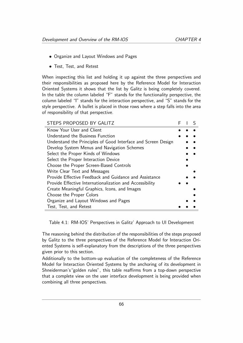
Development and Overview of the RM-IOS CHAPTER 4
� Organize and Layout Windows and Pages
� Test, Test, and Retest
When inspecting this list and holding it up against the three perspectives andtheir responsibilities as proposed here by the Reference Model for InteractionOriented Systems it shows that the list by Galitz is being completely covered.In the table the column labeled “F” stands for the functionality perspective, thecolumn labeled “I” stands for the interaction perspective, and “S” stands for thestyle perspective. A bullet is placed in those rows where a step falls into the areaof responsibility of that perspective.
STEPS PROPOSED BY GALITZ F I S
Know Your User and Client • • •Understand the Business Function • • •Understand the Principles of Good Interface and Screen Design • •Develop System Menus and Navigation Schemes • •Select the Proper Kinds of Windows • •Select the Proper Interaction Device •Choose the Proper Screen-Based Controls •Write Clear Text and Messages •Provide Effective Feedback and Guidance and Assistance • •Provide Effective Internationalization and Accessibility • •Create Meaningful Graphics, Icons, and Images •Choose the Proper Colors •Organize and Layout Windows and Pages • •Test, Test, and Retest • • •
Table 4.1: RM-IOS’ Perspectives in Galitz’ Approach to UI Development
The reasoning behind the distribution of the responsibilities of the steps proposedby Galitz to the three perspectives of the Reference Model for Interaction Ori-ented Systems is self-explanatory from the descriptions of the three perspectivesgiven prior to this section.
Additionally to the bottom-up evaluation of the completeness of the ReferenceModel for Interaction Oriented Systems by the anchoring of its development inShneiderman’s“golden rules”, this table reaffirms from a top-down perspectivethat a complete view on the user interface development is being provided whencombining all three perspectives.
66

Development and Overview of the RM-IOS CHAPTER 4
4.4 RM-IOS - Six Questions for a Model
The description of the Reference Model for Interaction Oriented Systems con-cludes with the answering of six questions. The answers to these questionsprovide an overview of the meta-structure of a model and thereby unmistakablyposition the model and define the legitimacy of the research efforts invested intoit. Also the problem domain and the solution domain are addressed in the lasttwo questions.
4.4.1 Questions for a model
According to Mahr’s concept of a model in [Mah08], the two core questions anymodel must be able to answer are the questions “what is the model a modelof” and “what is the model a model for”9. In each of the answers to thesequestions lies one half of the dual nature of any model. While giving the answersto these two questions respectively might appear mundane, that would only bethe case when formulating very generic, and thus imprecise answers10. Thesewould then not be helpful at all, as the answers to these questions position themodel in the perception of the user and thus preload his view on the model withcertain expectations regarding the purpose, subsequently following, the utility ofthe model.
A third question a model can be queried with is the question “who is the modelfor”. As the answer to that question helps to illuminate why certain modelingdecisions have been thus made, and also legitimates the existence of the modelin respect to its intended purpose; an especially plausible point for a model thataims to be of real, applied use, such as this Reference Model for InteractionOriented Systems. The fourth question then, the counterpart to the third, is thequestion “whom is the model from” and should help furthering an understandingof the structural peculiarities of a model in respect to what knowledge and mentaltools were available to the creator of the model.
The answers to these questions then should serve as, both, a mental outline thatis drawn and background that is painted in which the actual model can then beviewed, inspected, and understood as closely to its intended purpose as possible.Additionally it seems equally important to state explicitly what this ReferenceModel for Interaction Oriented Systems is not a model of or for and these will
9Mahr dissects these two questions even further by exposing the existence of a model’scargo, but for the purpose of this thesis, this depth is not necessary and can be reduced to thetwo questions just stated.
10For example by answering the two questions with: “a model of interaction oriented sys-tems” and “a model for interaction oriented systems”.
67

Development and Overview of the RM-IOS CHAPTER 4
be weaved into the answers of the just listed questions.
The following paragraphs now try to offer all these answers and descriptions.
What is RM-IOS a model of?
RM-IOS is a descriptive, perspective based model of the nature of the entities,their relations to one another, and the resulting structures in an interactionoriented system. It provides a generic, abstract structure, i.e. meta-structure,which describes the external functions and services available to the user of theinteraction oriented system, the means available to the user to interact with thesystem, thus accessing the provided functions and services, and the way theseare presented to him from an aesthetic point of view.
It is not a model of a particularly good or lauded interaction oriented system andas such does not include any qualitative assessments. Rather it is a lexical refer-ence that describes certain invariable aspects of any interaction oriented system.It is also especially not a model of a development process or any methodology forthat matter. It is not a model of a certain technical realization of an interactionoriented system, that is to say, that in effect the Reference Model for Interac-tion Oriented Systems itself is independent of any implementation or technicalrealization.
What is RM-IOS a model for?
RM-IOS is a descriptive, perspective based model for describing (i.e. modeling)interaction oriented systems, which can then be utilized for the specification,verification, analysis, comparison, and evaluation of interaction oriented systems.
It is not a model for modeling the internal functions and services of an interactiveoriented system, but merely includes elements to model the external functionsand services of an interactive oriented system. While the user is being part ofthe model, the Reference Model for Interaction Oriented Systems does not servethe purpose of user modeling as done by other models, for example the Personasmodel approach by Alan Cooper [CRC07]. Furthermore, the Reference Modelfor Interaction Oriented Systems does not provide the means for environmentmodeling. Certain model elements appreciate the influence the environment canhave on the usability of a system, i.e. the effect of noise on the perceivability ofaudio signals emitted by the system, however, these model elements are neithermeant nor suitable for extensive environment modeling.
68

Development and Overview of the RM-IOS CHAPTER 4
Who is RM-IOS for?
It is the author’s sincere hope that the model will be for the benefit of the end-user of interaction oriented systems, in that the model’s contribution is beneficialto the user interface development process. However, the end-user will in mostcases never have anything to do with this model. But this ambition and view isa perspective the author thinks is important to maintain in order to not fall intoan overly technology oriented perspective.
That being said, the model effectively is for those people directly involved in theuser interface development process, i.e. engineers, software developers, design-ers, and interaction specialists11. These experts from different domains shouldhopefully find the Reference Model for Interaction Oriented Systems helpful whendescribing, specifying, verifying, analyzing, evaluating, comparing, and - funda-mentally important - communicating about and their view on interaction orientedsystems with one another.
Whom is RM-IOS from?
The creator of the model has a background in computer science, with a focuson formal models and modeling methodologies. Thus the dominant perspectivethroughout the creation of the model was one mainly from an engineering pointof view. From this fact several observations about the creation of this model canbe made, i.e. about the procedural method of creating this model and the natureand quality of the model itself. The author himself draws his own conclusionsand offers them to the reader in section 5.7.
What is RM-IOS’ problem domain?
In engineering disciplines the term “problem domain” is used to identify therelevant aspects and areas of expertise needed to examine the topics central tosolving the challenge posed by the circumstance of interest.
Defining the problem domain of a situation of interest immediately determinesthe direction and characteristics of the solution approach12. Also, the definition
11One could argue that an “interaction specialist” must be all of those combined, and surelythe newly found discipline of interaction specialists will be adequately versed in all scientificfields relevant to user interface development; enough to have a holistic view on the design anddevelopment of user interfaces. However, there will probably always be the software developerlikely with a background in computer science or programming, and the designer likely with abackground in graphical or animated arts who will also be part of the user interface developmentprocess.
12This is not to be confused with the actual solution as to one challenge and its identified
69

Development and Overview of the RM-IOS CHAPTER 4
of the problem domain affixes the criteria the solution will have to be held upagainst in order to decide, whether the proposed solution actually addresses thechallenges posed by the elements of the problem domain or is just a solutionpossibly to a completely different problem (see [Jac01] for a discussion of theimportance of a well understood and defined problem domain in the realm ofsoftware development).
The following aspects constitute the problem domain of the Reference Model forInteraction Oriented Systems introduced in this thesis:
� the conceptual and analytical part of user interface development
� the abilities and limitations of the user’s perception
� the system the user interacts with, in particular the functionality the systemoffers to the user, the way in which the user interacts with the system, andthe aesthetic aspects of the presentation of the system to the user
� the communication between the different domains of skill and expertiseneeded during the user interface development process, and recognition ofthe different areas of responsibility based on those skill sets
What is RM-IOS’ solution domain?
Contrary to the problem domain, the solution domain is not so much a matter ofa preset definition, but rather comprises the entirety of all possible solutions tothe challenges posed by the problem domain. The particular solution proposed toanswer to the problem domain, in this case the Reference Model for InteractionOriented Systems and its construction is one possible solution of all conceivablesolutions.
The solution offered in this thesis comprises a perspective based reference modelthat has been created by following a rational, analytical approach to the problemdomain and in its underlying structure has followed the style of and includesaspects from the reference model of open distributed processing (RM-ODP).
In an attempt to realize the fundamental concept of a useful Reference Model forInteraction Oriented Systems, namely that “[...]a good reference model shouldprovide a structure which is common to all user interface support systems” (asuggestion made by Lynch and Meads [LM86]) the herein proposed model focuseson the timeless, technology-independent meta-aspects of a user interface and theuser’s interaction with it.
problem domain generally several solutions are possible. However, the problem domain doesstrongly influence the solution as what has not been included in the definition of the problemdomain will obviously not be considered during the finding of a suitable solution.
70

Chapter 5
Reference Model for InteractionOriented Systems
5.1 RM-IOS
This chapter presents the reference model for interaction oriented system whichhas been created for this thesis.
It contains the actual model with the following section 5.6 providing a structuraloverview of the entire model by presenting four UML class diagrams, each de-picting one of the parts of the model. These diagrams are intended to provide aquick graphical overview of the entire structure of the model and should help toapproach the model.
5.2 Foundation
5.2.1 Interaction Oriented System
Definition
An interaction oriented system can be described by a non-empty set of scenesbelonging to one system.
Explanation
Defining an interaction oriented system by including it as an element of theReference Model for Interaction Oriented Systems provides the anchoring elementin the problem domain the Reference Model for Interaction Oriented Systems
71

Reference Model for Interaction Oriented Systems CHAPTER 5
offers one solution for. The concept behind an interaction oriented system then isthe entirety of a system the user interacts with in regard to the three perspectivesof functionality, interaction, style. It comprises software and hardware elementsalike, and thus is not reduced to a mere description of the interaction elementspresented on a display. All elements available to the user, whether virtual assoftware elements, or actual as hardware elements, are part of the description ofan interaction oriented system.
The inclusion and equalization of hardware elements and software elements allowsfor an encompassing description of interaction elements available to the user andthus allows for a holistic description of the possible interaction with a system.
Example
The interaction elements of a smartphone, i.e. the virtual elements on the screenand the actual elements on the device itself are an example of an interactionoriented system. Such an interaction oriented system is being examined in thecase study in chapter 6. Another example for an interaction oriented systemis the cockpit of a car where in contemporary cars the majority of interactionelements still are hardware interaction elements. The classic desktop computerwith its immense versatility achieved by being able to run a plethora of differentapplications is, of course, also an example for an interaction oriented system.
5.2.2 Scene
Definition
A scene is a set of interaction objects available to the user at a certain locationin time and a certain state of the interaction oriented system. The interactionobjects of a scene have a distinct spatial relation to one another. A scene isactivated by a scene triggering interaction object. A scene is not empty. The setof all scenes of an interaction oriented system comprises all possible interactionswith the system.
Explanation
An interaction oriented system must be structured in such a way that it enablesthe use of the Reference Model for Interaction Oriented Systems during theanalysis and synthesis of it. The scene concept provides this structure by allowingthe modeler to create suitable “snapshots” of the interaction oriented system.The “non-emptiness” of a scene must not be confused with a situation, where a
72

Reference Model for Interaction Oriented Systems CHAPTER 5
scene may not present any visible interaction objects to the user, thus appearingempty.
Example
An obvious scene is the single window of a “wizard”-dialogue. The user ispresented with a set of interaction objects and upon clicking the “next” buttonis taken to a new scene. Also, the screen of a smartphone at a certain momentduring the using of an app is a good example of a scene. However, a scene is notlimited to the virtual elements on the screen but can also include the availablehardware interaction elements of a device. An example of a scene can be foundin the case study of this thesis starting on page 111 ff.
5.2.3 User
Definition
A person who uses the services offered by an interaction oriented system byproviding input and being the designated receiver of the output. The user doesnot have to be a single real person but can be understood as a certain class ofusers.
Explanation
Every interaction oriented system must communicate with a user through thetransfer of input and output. And during the modeling of a system the user willtypically have to be defined, as a well defined user is of fundamental importance todesigning a satisfying user-experience. The modeling of the user itself, however, isnot part of this reference model, as other, well established models and approachesalready exist. But during the modeling of a system with this reference modelthe user will be a model-element that needs to be referred to and included inmodeling the interaction processes with the system.
User modeling is a discipline of its own and several methods exist (for examplethe “Personas” approach [CRC07]) for this task. It is not part of this model tocover techniques of user modeling but in the context of this model, the user ispart of the model but not part of the system. A system is built with a certainuser in mind and different users come with different abilities and requirementswhich can, among other aspects, affect the perceptibility and perceivability ofsystem elements.
73

Reference Model for Interaction Oriented Systems CHAPTER 5
Example
A class of users could be defined as people between 50-60 years of age, with noneto limited technical background knowledge and experience. Another examplewould be a group of users between 14-16 years of age, with a strong technicalbackground.
5.2.4 Input
Definition
Information exchanged between the system and the user where the informationis provided to the system by the user through interaction objects.
Explanation
Whenever a user interacts with a system some sort of input is required to yieldthe output generated by the system. As such, input is the parameter to theoffered functionality of a system.
Example
The PIN users type at an ATM, their name entered in a web-form, the numberspunched in on a dial-pad, the selection of a ticket from a public-transportationticket-vending machine, the biometric data scanned from their fingertip placeda biometric scanner, the gesture made into a camera, the spoken word into amicrophone, all are examples of input.
5.2.5 Output
Definition
Information exchanged between the system and the user where the informationis provided to the user by the system through interaction objects.
Explanation
For a system to be of any use at all, some sort of output must be provided. Inthat output lies the essence of the system’s offered functionality.
74

Reference Model for Interaction Oriented Systems CHAPTER 5
Example
Presenting the result of a calculation, offering several buttons to make some sortof choice, vibrating and ringing on an incoming call, displaying a little icon thatnotifies the user that the system is currently busy all are examples of output.
5.2.6 Maximum Value
Definition
If an input or output is limited to a highest possible value, then this is themaximum value.
Explanation
While some input is being entirely unrestricted, often there is a limit constrainingthe possible input. If the limit is or can be understood as a top limit, it is themaximum limit. This does not only relate to numerical input but can be specifiedin a more abstract way.
Example
The most obvious example is a numerical restriction, i.e. limiting an input toa highest possible number. But a date is also limited to a selection of twelvemonths. And the ability to upscale an image could be restricted to a certain size,thus imposing a maximum limit on the pixel size of the scaling.
5.2.7 Minimum Value
Definition
If an input or output is limited to a lowest possible value, then this is the minimumvalue.
Explanation
While some output is being entirely unrestricted, often there is a limit constrainingthe possible output. If the limit is or can be understood as a bottom limit, itis the minimum limit. This does not only relate to numerical input but can bespecified in a more abstract way.
75

Reference Model for Interaction Oriented Systems CHAPTER 5
Example
The most obvious example is a numerical restriction, i.e. limiting an input to alowest possible number. But requiring the user to provide at least one value ofa selection, or restricting the output of an image to be at least of a certain sizeare also examples for a more abstract minimum value.
5.2.8 Input Range
Definition
Input can be limited to a minimum and/or maximum value. The range of valuesin between is the input range.
Explanation
Input that is restricted by, both, a minimum and maximum value is confined tothe input range defined by those two limits. The most obvious case would be arestriction to a numerical range, but also more abstract situations are possible,where a range is defined by the enumeration of input objects.
Example
Restricting input to, for example, a number between 1 to 10 is a very obviousinput range. But also the restriction of input to the letters of a certain alphabetis a preset input range definition. The same holds true for being able to resizean image to a certain maximal and certain minimal size.
5.2.9 Output Range
Definition
Output can be limited to a minimum and/or maximum value. The range ofvalues in between is the output range.
Explanation
Output that is restricted by, both, a minimum and maximum value is confined tothe output range defined by those two limits. The most obvious case would be arestriction to a numerical range, but also more abstract situations are possible,where a range is defined by the enumeration of output objects.
76

Reference Model for Interaction Oriented Systems CHAPTER 5
Example
Defining output to, for example, a number between 1 to 10 is a very obviousoutput range. But also the restriction of output to the letters of a certainalphabet is a preset output range definition. An image, that is never going to bedisplayed smaller or larger than a certain size is another example for a restrictingoutput range.
5.2.10 Selection
Definition
A selection is a defined set of data typically used for specifying all possible inputor all possible output.
Explanation
When the possible input or output is limited to a certain selection of data it isuseful to be aware of this selection as it can strongly influence the kind of requiredinteraction. This model element focuses the awareness during the modelingprocess towards this potential situation and allows for specification of selectionsduring the conception of the system.
Example
Unicode symbols, alphanumerical symbols, the three values “red, green, blue” or“on, off, stand-by” are example for predefined selections of input or output.
5.2.11 Input Modality
Definition
The mapping of input to a certain kind of sensor or device of the computer.
Explanation
Input must be provided by means of at least one input modality. Depending onthe situation and use-context some input modality might be better suited thananother.
77

Reference Model for Interaction Oriented Systems CHAPTER 5
Example
Entering text by pressing the keys on a keyboard, or speaking the text into amicrophone are two examples for haptic and audio input modality.
5.2.12 Output Modality
Definition
The mapping of output to one of the human senses.
Explanation
The system must utilize at least one output modality in order to present outputto the user. Depending on the situation and use-context some output modalitymight be better suited than another.
Example
Todays most common output modalities are the visual modality, i.e. presentingoutput on a display, and audio modality, i.e. playing sounds. Haptic modalityoutput can often be found in controllers for video-games via vibrating, and vi-brating is also commonly found in cell phone devices to indicate for example anincoming message or incoming call. Other output modalities such as gustation,olfaction, and thermoception modalities are not part of contemporary systems.
5.2.13 Input Type
Definition
The type of input in terms of its nature.
Explanation
Once an abstract conception of a system is being concretized, an input typefor the input must be defined. Input types could be “string”, “number”, butalso more complex and composite types such as “date”, “address”, or any otherapplication specific data type. A composite input type is an input type comprisingother input types. A complex input type is an input type which composition willnot be explained further at the scope of modeling.
78

Reference Model for Interaction Oriented Systems CHAPTER 5
Example
A name is a simple input of type string. An address is a composite input of typeaddress which in turn comprises strings and numbers. A biometrical fingerprintis a complex input which internal structure is not being dissected at the currentscope of modeling.
5.2.14 Output Type
Definition
The type of output in terms of its nature. Output types could be “string”, “num-ber”, but also more complex and composite types such as “date”, “address”, orany other application specific data type.
Explanation
Once an abstract conception of a system is being concretized, an output typefor the output must be concretized. Output types could be “string”, “number”,but also more complex and composite types such as “date”, “address”, or anyother application specific data type. A composite output type is an input typecomprising other input types. A complex output type is an output type whichcomposition will not be explained further at the scope of modeling.
Example
A name is a simple output of type string. An address is a composite outputtype comprising strings and numbers. A picture is a complex output type whosestructure is not further modeled at the current scope.
5.2.15 Stream
Definition
A stream is an input type or output type that is continuous over a period oftime. A stream typically has an inherent chronicity that must be adhered to inorder to not alter the information significantly.
79

Reference Model for Interaction Oriented Systems CHAPTER 5
Explanation
Data such as music or a movie can obviously not be presented “at once” butinstead needs to be input or output continuously over a period of time.
Example
A two-way video conference is an example of a visual and audio input and outputwhere the data captured by the camera and the microphone need to be receivedand presented continuously.
5.2.16 Interaction Object
Definition
An interaction object is an object that receives input or presents output. Aninteraction object can contain one or more interaction objects.
Explanation
An element in the user interface that receives input or presents output is aninteraction object. Depending on the viewpoint an interaction object possessesdifferent attributes. Functionality attributes from the functionality viewpoint,interaction attributes from the interaction viewpoint, and style attributes fromthe style viewpoint. This is the basis for letting one identifiable element beingmodeled from the three distinct perspectives with different interests dependingon the viewpoint.
Example
A virtual button on the user interface is a (graphical) interaction object, theringtone of a cellphone is a (acoustical) interaction object, a real button on akeyboard is a (haptical) interaction object, and a touchscreen is a (graphical andhaptical) interaction object.
5.2.17 Trigger
Definition
A trigger is an input type or output type which provides only the atomic infor-mation that it has occurred.
80

Reference Model for Interaction Oriented Systems CHAPTER 5
Explanation
Some input does not transfer entered information from the user to the systembut merely allows the system to understand that some event has taken place.
Example
The user clicking a “send” button on a composed mail, pushing the hang-upbutton on a telephone, or activating a motion-sensor by moving are examples oftrigger-inputs.
5.2.18 Scene Trigger
Definition
A scene trigger is a trigger that activates a new scene.
Explanation
Applications present themselves to the user as a collection of scenes. A scenechange happens when upon the interaction with an object a new scene is beingpresented to the user. The interaction object that triggers that scene change isa scene trigger.
Example
A scene presents itself to the user as a virtual form, comprising textfields for input,a submit-button, and a cancel-button. Pressing the submit- or cancel-buttoncauses the scene to change, as in the former case a scene will be presentedto the user confirming the submission, and in the latter case a scene will bepresented to the user confirming the cancellation of the form. The submit- andthe cancel- button in this case both are scene triggers.
81

Reference Model for Interaction Oriented Systems CHAPTER 5
5.3 Functionality Viewpoint
The functionality viewpoint describes the system’s aspects relevant to the pro-vided functionality. This is accomplished by describing the system as a black-boxthat is defined solely by the system’s input and output exchange, i.e. the answersto the two questions:
� What input does the system require?
� What output does the system provide?
5.3.1 Interaction Object
Definition
An interaction object possesses functionality attributes.
Explanation
An interaction object in the user interface is a way to exchange input and outputbetween the user and the system. The functionality viewpoint inspects such aninteraction object on the basis of which input it is to receive or which output itis to present.
Example
A text-field is an interaction object for a user to enter, for example, his name.A button is an interaction object for a user, for example, to trigger sending amessage. A non-editable text-field is an interaction object for the system to, forexample, display the result of a calculation.
5.3.2 Input
Definition
Information exchanged between the system and the user where the informationis provided to the system by the user. Input is a functionality attribute. Input isof a certain input type. Input may be limited by a minimum and/or maximumvalue or by a selection.
82

Reference Model for Interaction Oriented Systems CHAPTER 5
Explanation
Whenever a user interacts with a system some sort of input is required to yieldthe output generated by the system. As such, input is the parameters to theoffered functionality of a system.
Example
Users typing their PIN at an ATM machine, entering their name in a web-form,punching numbers on a dial-pad, selecting a ticket from a public-transportationticket-vending machine, placing their finger on a biometric scanner all are exam-ples of input.
5.3.3 Output
Definition
Information exchange between the system and the user where the information isprovided to the user by the system. Output is of a certain output type. Outputmay be limited by a minimum and/or maximum value.
Explanation
From the functionality viewpoint output is a matter of output type and possiblyan output range associated with it. Whenever a user interacts with a systemsome sort of output is being generated by the system. This output effectivelyprovides the functionality of the system.
Example
A calculator provides the result of the request calculation as output. A navigationsystem provides an overview of an area and driving directions. A music-playeroutputs the name of the song and album, and the sound.
5.3.4 Input Type
Definition
The type of input in terms of its nature.
83

Reference Model for Interaction Oriented Systems CHAPTER 5
Explanation
Input types could be “string”, “number”, but also more complex and compositetypes such as “date”, “address”, or any other application specific data type. Acomposite input type is an input type comprising other input types. A complexinput type is an input type which composition will not be explained further atthe scope of modeling.
Example
A name is a simple input of type string. An address is a composite input of typeaddress which in turn comprises strings and numbers. A biometrical fingerprintis a complex input which internal structure is not being dissected at the currentscope of modeling.
5.3.5 Output Type
Definition
The type of output in terms of its nature. Output types could be “string”, “num-ber”, but also more complex and composite types such as “date”, “address”, orany other application specific data type.
Explanation
Output types could be “string”, “number”, but also more complex and compositetypes such as “date”, “address”, or any other application specific data type. Acomposite output type is an input type comprising other input types. A complexoutput type is an output type which composition will not be explained further atthe scope of modeling.
Example
A name is a simple output of type string. An address is a composite outputtype comprising strings and numbers. A picture is a complex output type whosestructure is not further modeled at the current scope.
84

Reference Model for Interaction Oriented Systems CHAPTER 5
5.4 Interaction Viewpoint
Describing the aspects of a system relevant to the interactability and usability ofthe system.
5.4.1 Interaction Object
Definition
An interaction object possesses interaction attributes.
Explanation
An interaction object in the user interface is a way to exchange input and outputbetween the user and the system. The interaction viewpoint inspects such aninteraction object on the basis of how input is to be entered and how output isto be presented.
Example
A turn-knob is an interaction object that will be turned by the user to receivethe user’s input. A slider is an interaction object that will be moved from oneend of its scale to the other to receive the user’s input. Both interaction objectscould be used for the same task, i.e. adjusting volume, but one might be bettersuited from the interaction viewpoint than the other.
5.4.2 Input
Definition
Input is an interaction attribute. Input is information exchanged between thesystem and the user where the information is provided to the system by the user.Input has at least one input modality.
Explanation
Whenever a user interacts with a system some sort of input is required to yieldthe output generated by the system. As such, input is the parameters to theoffered functionality of a system. From the interaction viewpoint the interest ininput lies in how it is being entered, i.e. the input modality.
85

Reference Model for Interaction Oriented Systems CHAPTER 5
Example
The user pushing keys on a keyboard, tapping a certain location on the screen,or speaking into a microphone are all examples of input.
5.4.3 Output
Definition
Output is an interaction attribute. Output is information exchange between thesystem and the user where the information is provided to the user by the system.Output has at least one input modality.
Explanation
The one reason why a system is being used and a user interacts with it, i.e.provides input, is the output a system is able to generate. With the systemseen as a “blackbox” the output is what lets a user make assumptions about theworking of the system. Thus output can either have feedback character, i.e. toinform the user about an accepted interaction attempt, or can deliver the resultof input manipulation to the user.
Example
A screen showing a picture, or a textbox displaying a name, the speaker of anavigation system emitting the driving-directions, or the vibrating of a cell phoneon an incoming message are examples of output.
5.4.4 Feedback
Definition
Output that immediately follows the provision of input to confirm the act ofproviding input.
Explanation
The user has per se no way of telling whether her interaction with the systemhas been registered by the system. Feedback is needed to inform the user thather action has been registered.
86

Reference Model for Interaction Oriented Systems CHAPTER 5
Example
A common kind of feedback is the visual change of state of a “pushed down”button. It informs the user that her action of pushing the button has beenregistered. The click sound emitted when pushing keys or activating interfaceelements is an example for audio feedback. Sometimes the functionality of anaction already provides feedback in and by itself, like the letters that appear onthe screen when a letter-key has been pushed.
5.4.5 Perceptibility
Definition
Perceptibility is an attribute of the relation between “input and the system” and“output and the user”. Information exchanged is perceptible when the stimulusit triggers is within the boundaries of the user class senses’ registration capabilityor the system device’s registration capability respectively. The question of per-ceptibility is highly dependent on the innate abilities of the user and the technicalsophistication level of the system.
Explanation
Free of impeding and overlapping noise a signal can be detectable by the humansenses or not be detectable by the human senses. Assuming that a signal is beingemitted in a distraction free environment, the question, whether that signal wouldbe registered by the human senses of a user answers the perceptibility of thatsignal.
Example
The sound generated by blowing into a dog whistle is not perceptible by thehuman ear, the sound generated by activating a car’s horn is perceptible by thehuman ear. A microscopically small dot is not perceptible by the human eye, thedot at the end of this sentence is perceptible by the human eye.
5.4.6 Perceivability
Definition
Perceivability is an attribute of the relation between an “input and the system”and “output and the user”. Information exchanged is perceivable when the
87

Reference Model for Interaction Oriented Systems CHAPTER 5
interferences of the environment do not eliminate its perceptibility.
Explanation
Given the premise of perceptibility of a signal the environmental noise (not neces-sarily acoustical noise) may make it imperceivable to the human sense, overlayingthe signal or distracting from it. Thus, perceivability here is defined as the abilityof an object to trigger a sufficient sensory stimulus. The question of perceivabilityis highly dependent on the innate abilities of the user.
Example
A word spoken at regular volume is a perceptible event, however, spoken next toa starting jet-plane it becomes imperceivable. A needle is a visually perceptibleobject, however, in the proverbial haystack its perceivability becomes extremelydiminished.
5.4.7 Visibility
Definition
Visibility describes the visual perceptibility of an interaction object to a user.
Visibility is only concerned with the actual visibility state of an interaction objectand not used to describe whether a layout situation prevents an interaction objectfrom being seen or not because of an entity blocking the line-of-sight (see 5.4.8).
Explanation
Perceptibility is the general term for describing the ability of a user’s senses toregister a sensory stimulus. The term visibility now is concerned only with thevisual perceptibility of an object, thus, per definition, it applies only to objectswhich trigger a visual stimulus.
Example
Any object that emits or reflects light is an object which can be evaluated re-garding its visibility to the user.
88
Reference Model for Interaction Oriented Systems CHAPTER 5
5.4.8 Viewability
Definition
Viewability describes the visual perceivability of an interaction object, i.e. if theline-of-sight is not being obstructed by something else, or if the environmentalvisual distraction allows for the object to still be perceived.
Explanation
An object can be visible to the user but due to issues of viewing angle of thedisplay, obstructed line of sight, overly distracting visual noise the object becomesnon-viewable. The question of viewability is highly dependent on the innateabilities of the user.
Example
A black line drawn with a ballpoint pen on a white paper is from a distance of30cm, both, visible and viewable. The same black line drawn on a black paperis most likely non-viewable, as the contrast to the background is not sufficientenough. The keypad for entering the pin number at an ATM machine is clearlyvisible, but the flaps attached to it to prevent others from watching the userentering her PIN number makes it non-viewable.
5.4.9 Audibility
Definition
Audibility describes the auditory perceptibility of a signal.
Explanation
The human ear is being attributed with being able to hear audio signals withina range of 12 Hz to 20,000 Hz [Ols67, p. 249], although that range shrinks overthe lifetime of a human being. Thus, for a sound to be audible it must be withinthat range of pitch. The pitch of the sound generated by a dog whistle, forexample, is above 20,000 Hz and thus not audible by the human ear.
89

Reference Model for Interaction Oriented Systems CHAPTER 5
Example
Sounds in the ultrasonic spectrum of sound are not audible by a human ear. Thesound emitted by a car’s horn is audible to the human ear.
5.4.10 Hearability
Definition
Hearability describes the auditory perceivability of a signal.
Explanation
Given the audibility of a signal for a user as a premise the hearability then de-scribes whether that signal is also still audible in certain situations, i.e. the sce-narios in which the system is being used. This attribute reminds of the fact, thata signal might be audible when emitted in a silent environment but that given acertain scenario the environmental noise might drown the signal, thus, renderingit useless.
Example
The beeping tone of an incoming message on a cellphone is an audible signal asit is loud enough to be heard and in a silent room it is hearable. However, thatbeeping tone is being rendered non-hearable when emitted in a driving car witha turned up stereo-system, as the noise present in that situation is much louderthan the beeping tone of the cell phone.
5.4.11 Tangibility
Definition
Tangibility describes the haptic perceptibility of an interaction object.
Explanation
When it is possible to touch an object that object is tangible.
90

Reference Model for Interaction Oriented Systems CHAPTER 5
Example
A turning knob is a tangible object, as it can be touched and felt. A virtual buttonon a touchscreen, however, is not tangible. The touchscreen itself is a tangibleobject but the button is not. Critically, depending on the modeling situation itmight be sensible to model a button on a touchscreen as a tangible object, butthe distinction is something that should be recognized while modeling.
5.4.12 Feelability
Definition
Feelability describes the haptic perceivability of an interaction object.
Explanation
When an interaction object is to be operated by touching manipulation, it iscritical that the interaction object can be easily felt and handled by the user.The attribute of feelability allows for the modeling of this aspect.
Example
A button that is flush with the surface it is on is possibly not feelable to a userwho is to operate it without looking. Tiny keys on a very small keyboard mightalso not be individually feelable. Feelability is an aspect to be especially keptin mind when an interaction object is expected to be operated without the useractually looking at it, too.
5.4.13 Mode of Operation
Definition
Mode of operation is an interaction attribute and describes the nature of inputan interaction object is able to receive.
Explanation
While the modality of an input interaction describes which of the human senses isinvolved, the mode of operation then describes the nature of the input interactionitself. A mode of operation is always a distinct way of receiving input in a givenmodality.
91

Reference Model for Interaction Oriented Systems CHAPTER 5
Example
A virtual button on a touch sensitive surface and an actual push-in button onsome panel are both interactions in the realm of haptic modality. Yet they areobviously different as in the former case a certain area on a touch sensitive screenmust be touched, in the latter a certain area must be actually moved, i.e. pushedin. Another example for two different mode of operations in the realm of hapticmodality would be a slider along a one dimensional axis and turn knob that canbe rotated.
An example in the realm of audio modality would be a light switch that is acti-vated by a speaking a certain word, or activated by clapping the hands.
An example in the realm of visual modality would be holding up a bar code to ascanner or holding up a picture to a scanner.
5.4.14 Mode of Presentation
Definition
Mode of presentation is an interaction attribute and describes the nature ofoutput an interaction object presents to the user.
Explanation
While the modality of an output interaction describes which of the human senseis involved, the mode of presentation then describes the nature of the outputinteraction itself. A mode of presentation is always a distinct way of presentingoutput in a given modality.
The mode of presentation effectively models the actual occurence of the modality-bound output.
Example
In the realm of visual modality an icon of a printer is a different mode of presen-tation than a text in a framed box reading “print”.
In the realm of audio modality a beep sound is a different mode of presentationthan a voice speaking a word.
92

Reference Model for Interaction Oriented Systems CHAPTER 5
5.5 Style Viewpoint
Describes the styling and presentation of a system.
5.5.1 Interaction Object
Definition
An interaction object possesses style attributes.
Explanation
An interaction object is an element of the user interface that possesses certainstyle attributes. The style viewpoint does not describe the functionality that isassociated with a certain interaction element, although that is not to say thatthe functionality is being ignored. It merely says that it is not part of the styleviewpoint, as the style viewpoint is concerned with how interaction elements arestyled and present themselves to the user from an aesthetic point of view.
Example
When inspecting a virtual button, the action that will be triggered by pushing itis part of the functionality viewpoint, the fact that it is a virtual button that canbe touched to be activated is part of the interaction viewpoint. The fact that itis of a certain color, has a certain shape, is placed at a certain location, theseattributes are part of the style viewpoint of an interaction object.
5.5.2 Style Attributes
Definition
Style attributes allow for the modeling of attributes of an interaction object independence of a modality when inspected from the style viewpoint.
Explanation
An interaction object has several different attributes, which are grouped into thethree perspectives: functionality, interaction, and style. Style attributes are thoseconcerned with the appearance and general aesthetics of an interaction object.
93

Reference Model for Interaction Oriented Systems CHAPTER 5
Example
Style attributes of the haptic modality are concerned with the haptic appearanceof an interaction object, for example ‘rough’, ‘smooth’, ‘soft’. Style attributesof the visual modality are concerned with the visual appearance of an interactionobject, for example ‘blue’, ‘round’, ‘to the left of ...’. Style attributes of the audiomodality are concerned with the audio appearance of an interaction object, forexample ‘loud’, ‘silent’, ‘fading’.
5.5.3 Haptic Style Attributes
Definition
Haptic style attributes describe the haptic appearance of an interaction object.
Explanation
Anything tangible has a certain haptic appearance. This haptic appearance canbe described by haptic style attributes.
Example
The firmness of an object or the haptic texture (see 5.5.4) of its surface are bothexamples of haptic style attributes.
5.5.4 Haptic Texture
Definition
Haptic texture is a haptic style attribute and describes the feel of an interactionobject’s surface.
Explanation
Every physical object has a surface. The haptic texture describes the feel of thatsurface.
Example
A surface might be rough, grooved, or smooth. It could have a rubbery or aglossy touch.
94

Reference Model for Interaction Oriented Systems CHAPTER 5
5.5.5 Visual Style Attributes
Definition
Visual style attributes are style attributes perceptible by the human’s opticalsense or a computer’s optical sensor.
Explanation
Every visible entity has certain visual attributes by which it can be described,specified, or identified. Any such attribute is a visual style attribute.
Example
In the realm of visual modality shape, color, placement, distance all are styleaspects of an interaction object.
5.5.6 Color
Definition
Color is a visual style attribute and describes an interaction object’s color.
Explanation
A visible entity can present itself in a certain color. Color is an important aspect inthe styling of user interfaces, as certain colors are culturally identified with certainimplication, i.e. red typically means “stop”, “danger”, “attention”, where greentypically means “go”, “safe”, “working” etc.
Example
The red color of a button, the green color of an LED, the blue color of a back-ground are examples of the color attribute.
5.5.7 Iconic
Definition
Iconic is a visual style attribute and describes the iconic expression of a visualinteraction object. If an interaction element possesses this attribute, it is an icon.
95

Reference Model for Interaction Oriented Systems CHAPTER 5
Explanation
Icons are small, simplified graphics. Icons are a prevalent aspect of graphical userinterfaces (GUIs) where they are used as graphical labels to identify commands,applications, and file types.
Icons are one of the fundamental aspects of today’s still widely used WIMP(“window, icon, menu, pointing device”) interfaces. In the context of softwarebased user interfaces, icons are little pictures that are used instead of words todistinctively convey a very specific meaning or give visual clues. Erwin Panofsky’s“Meaning in the Visual Arts” [Pan83] offers a detailed discussion on the natureof icons.
Example
The small graphic of a printer on a button indicates that pressing this buttonwill start some printing routine. A magnifying glass is commonly used to indicatesome sort of search or zoom functionality. These graphics are iconic and havebeen used as classic icons in the WIMP interaction domain.
5.5.8 Shape
Definition
Shape is a visual and haptic style attribute and describes an interaction object’sshape.
Explanation
The shape of an object is defined by the space the object occupies, either in 2Dor 3D space.
Example
Round, rectangular, square, elliptical, are all examples of shapes commonly foundin graphical user interfaces.
96

Reference Model for Interaction Oriented Systems CHAPTER 5
5.5.9 Size
Definition
Size is a visual and haptic style attribute and describes the dimensional expansionof an interaction object in at least one dimension. The size of all interactionobjects of a scene together with their positioning are the two most importantaspects concerning the scene and all its interaction objects and the availableprojection screen, i.e. typically a display.
Explanation
In graphical user interfaces the size of an interaction object is typically measuredin pixels. The width and height in pixels of a virtual button then describes the sizeof that button in relation to the resolution the virtual button is being displayedon. Often the size of non-rectangular graphical objects are given by giving thesize of an “invisible rectangle” the graphical object could be minimally containedby.
Example
250px high, 400px wide would be the size of a rectangle on any resolution. Around object of the same measure would be an ellipse. A hardware switch couldbe 4mm long and 2mm wide.
5.5.10 Position
Definition
Position is a visual and haptic style attribute and describes the location in spaceof an interaction object.
Explanation
Entities that have a visual representation occupy a certain location in space. On atwo dimensional plane the location in space is biuniquely given by their ordinatesalong the vertical and horizontal axis. In a three dimensional room the locationin space is biuniquely given by their ordinates along the vertical, horizontal, anddepth axis. In contemporary user interfaces the two dimensional layout of userinterface elements is still the most predominantly occurring visual layout. Theuser interface itself provides a certain appearance, composed by the positions
97

Reference Model for Interaction Oriented Systems CHAPTER 5
of its user interface elements, i.e. their positions and distances to one another.While changing this spatial structure of user interface elements is at least im-practical, often impossible in physical user interfaces, it happens very commonlyin virtual, i.e. software user interfaces. Here two different kinds of change inpositioning can be observed: elements changing their position but retaining theirdistance to certain other interface elements1 and elements changing their posi-tion and the distance to certain other interface elements. The absolute positionof interface elements in the user interface play a major role in the cognition ofthe user interface by the user and some interesting parallels can be observed be-tween user interface layout design and the typeface theory, which - among otheraspects of the written word - deals with the layout, kerning, size, and positionof letters towards one another. The position of all interaction objects of a scenetogether with their size (see 5.5.9) are the two most important aspects concern-ing the scene and all its interaction objects and the available projection screen,i.e. typically a display.
Example
An absolute positioning could be “5 pixels from the top edge of the window,20 pixels from the left edge of the window”, whereas an example of a relativepositioning could be “10 pixels to the left and 15 pixels above interaction object<x>”.
5.5.11 Distance
Definition
Distance is a visual and haptic style attribute and describes the size of spacebetween two interaction objects. It is a derived attribute caused by the positionof two interaction objects. Distance is measured in a units of length.
Explanation
Distance is an essential aspect of user interface design and constitutes one ofthe fundamental laws of perception in cognition-psychology, namely the “law ofproximity”, which states that objects that are spatially grouped are perceived asbelonging together [Met09]. This aspect finds its quintessential characteristicin the attribute of distance from one interaction object to one or many others.
1An example of this would be the scrolling of a website, where the elements “slide” up thescreen, but their position towards one another remains intact.
98

Reference Model for Interaction Oriented Systems CHAPTER 5
But besides the law of proximity distance also is important in the esthetic lay-out of the interface. The Apple Human Interface Guideline [Inc06] for examplestrongly recommends a margin of 20 pixels, which of course describes the dis-tance of the side edge of a window to the closest inner interaction object. Thedistance attribute thus allows the specification and checking of such aspects ofthe interface.
Example
10 pixels between virtual button “A”, and textfield “B” are an example of distancebetween two interaction elements.
5.5.12 Interval
Definition
Interval is a style attribute and describes the distance in time between two actsof information exchange. Interval is measure in units of time.
Explanation
Repetition of signals or events is often used in interaction oriented systems toincrease the chance of raising a user’s attention.
Example
The blinking of the cursor in a text-processing program is an example of aninterval occurring in output. The double-click on a mouse is an example of aninterval occurring in input. This blinking is defined by the interval, i.e. the timepassing, between the disappearing and reappearing of the cursor. Same holdstrue for audio signals, for example, alarms and notifications.
5.5.13 Font
Definition
Font is a visual style attribute. It is a specific character set of a particular typefacein a specific size and of specific weight and defines the appearance of text.
99

Reference Model for Interaction Oriented Systems CHAPTER 5
Explanation
Text is a fundamental part of visual user interfaces. Whether it is the actualoutput that is being provided as text, or it is text occurring in the labeling ofinteraction elements. This text by definition has a certain appearance which isdescribed by the font attribute.
Example
One of the most well-known fonts is the Arial typeface. “Arial, 12p, regular”would be an example of a font, namely, the typeface, the size, and the weight.
5.5.14 Terminology
Definition
Terminology is a visual or audio style attribute. Terminology is the specializedvocabulary or nomenclature for the words or compound words in the interface ofan interaction oriented system.
Explanation
Shneiderman recommends the usage of a homogenous terminology in order notto confuse the user with different terms for same functionality or identical termsfor different functionality. The terminology plays a vital part in the labeling ofinterface i.e. menu items.
Example
To “delete”, “discharge”, “erase”, “destroy” a row in a table are different termsfor (probably) the same functionality.
5.5.15 Audio Style Attributes
Definition
Audio style attributes are style attributes perceptible by the human’s auditivesense or a computer’s audio sensor.
100

Reference Model for Interaction Oriented Systems CHAPTER 5
Explanation
An audio signal can be described by its attributes. These attributes then arelabeled audio style attributes.
Example
In the realm of the audio modality the particular sound of a voice speakinginstructions of the user, or the particular clicking sound generated by a car’sturning lights are examples for style aspects of an interaction object.
5.5.16 Pitch
Definition
Pitch is an audio style attribute. It defines the perceived frequency of a sound.
Explanation
The pitch of a sound is commonly described as the tone being high or low. Pitchis caused by the variation in the frequency of vibration.
Example
A high pitched sound or a low pitched sound could be descriptions of an alarmsignal.
5.5.17 Timbre
Definition
Timbre is an audio style attribute. It describes the quality of a certain tone orsound.
Explanation
Timbre is what lets people distinguish between a piano and a trumpet bothplaying the same note. It has been said to be everything of a note that’s notpitch or loudness. It is often described by using adjectives from other senses’domains [MB79].
101
Reference Model for Interaction Oriented Systems CHAPTER 5
Example
A sound’s timbre can be warm, wooden, metallic, splashy, chirpy, mellow.
5.5.18 Loudness
Definition
Loudness is an audio style attribute. It describes the perceived volume of a sound.
Explanation
Loudness is not to be confused with strictly physical aspects of a sound such assound pressure level. Rather, it is the perceived volume of a sound and thus isan inherently subjective aspect [Ins73].
Example
A sound can be perceived as loud or silent and anywhere in between. This is theloudness of a sound as perceived by someone.
5.5.19 Olfactory Style Attributes
Definition
Olfactory style attributes are concerned with the signals perceived by the human’ssense for smell.
Explanation
While still almost non-existent in today’s user interfaces, the aspect of scent isincluded here mostly for the sake of completion.
Example
Scent is typically described by naming objects associated with a typical scent,i.e. a scent can be leathery, or burnt, or fruity.
102

Reference Model for Interaction Oriented Systems CHAPTER 5
5.5.20 Gustatory Style Attributes
Definition
Gustatory style attributes are concerned with the attributes of taste.
Explanation
Equally irrelevant in contemporary user-interfaces as olfactoric interaction ele-ments, the sense of taste is included here, also, mostly for the sake of completion.
Example
Salty, sweet, bitter, sour are examples of gustatory style attributes.
5.5.21 Thermoceptory Style Attributes
Definition
Thermoceptory style attributes are concerned with the perceived temperature ofa signal.
Explanation
Thermoceptory signals are not part of contemporary user interfaces but are in-cluded here as a stub for the sake of completion.
Example
Warm, cold, chilly, tepid, are examples of thermoceptoric style attributes.
5.5.22 Equilibrioceptic Style Attributes
Definition
Equilibrioceptic style attributes are concerned with the balance and alignment ofan object.
Explanation
With the advent of Nintendo’s Wii console the aspect of balance and alignmenthas become an established aspect of user interaction, albeit with the Wii console
103

Reference Model for Interaction Oriented Systems CHAPTER 5
almost exclusively in the realm of entertainment. Contemporary smartphonessuch as the Apple iPhone also make use of equilibrioceptic aspects by providingprograms with the possibility to react to users moving and tilting their phone.
Example
A user rotating her smartphone onto the side, thus triggering the display to rotate90◦, or steering an object on the display by tilting the phone along the two axisare examples of equilibrioceptic input.
An example of equilibrioceptic output is a car-simulator where the user sits insidea cabin and acceleration and deceleration is being simulating by tilting the cabinup and downwards, thus pressing the user into the back of the seat or out ofthe seat. In the isolated cabin where the eyes can not provide the additionalinformation needed to clearly identify the reason for the felt change in pressure,this technique adds a very important component to the simulation, thus makingit even more realistic.
5.6 Structural UML Class Diagrams of RM-IOS
Contained in this section are four UML class diagrams, each depicting one partof the RM-IOS:
� Figure 5.1 depicts the RM-IOS foundation
� Figure 5.2 depicts the RM-IOS functionality perspective
� Figure 5.3 depicts the RM-IOS interaction perspective
� Figure 5.4 depicts the RM-IOS style perspective
104

Reference Model for Interaction Oriented Systems CHAPTER 5
Figure 5.1: RM-IOS Foundation - UML Class Diagram
105

Reference Model for Interaction Oriented Systems CHAPTER 5
Figure 5.2: RM-IOS Functionality - UML Class Diagram
106

Reference Model for Interaction Oriented Systems CHAPTER 5
Figure 5.3: RM-IOS Interaction - UML Class Diagram
107
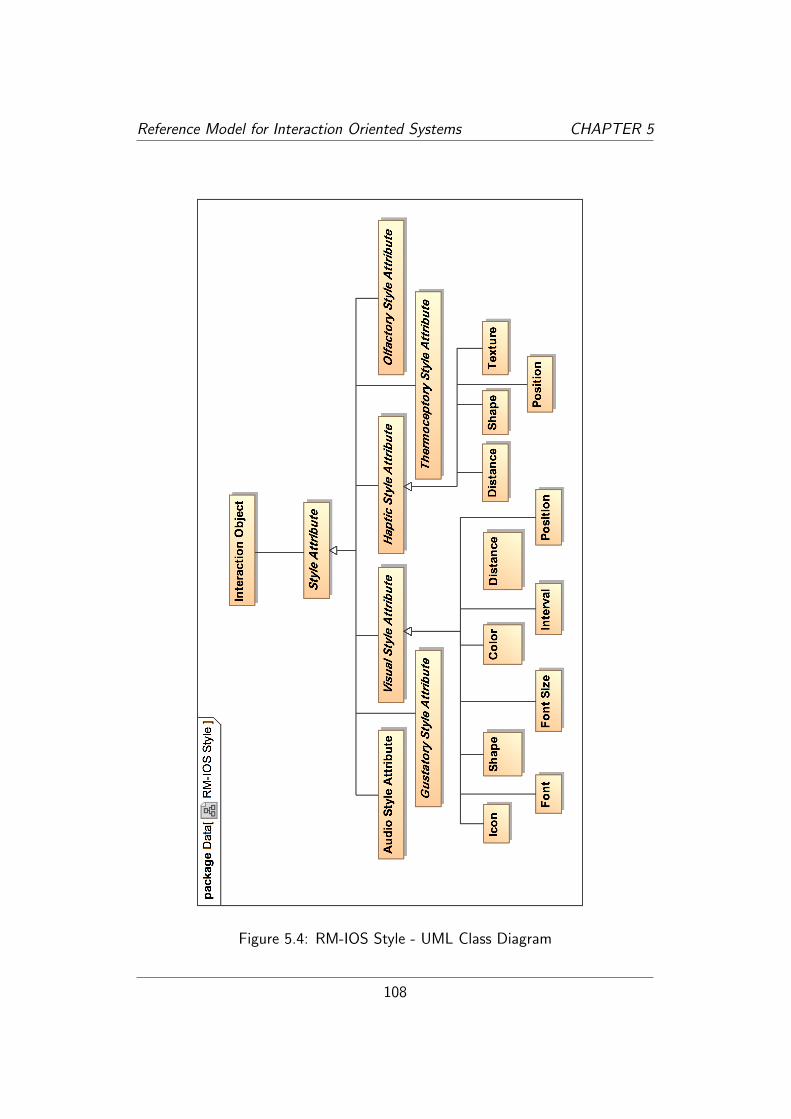
Reference Model for Interaction Oriented Systems CHAPTER 5
Figure 5.4: RM-IOS Style - UML Class Diagram
108

Reference Model for Interaction Oriented Systems CHAPTER 5
5.7 Conclusion
Shneiderman stipulates a holistic approach to the process of user interface de-velopment, acknowledging good usability as a systemic attribute of a system.The author of this thesis agrees with Shneiderman’s recommendation for such aholistic approach, but feels it is important to keep in mind that a discipline ascomplex and interdisciplinary as the domain of user interface development mustbe subjected to a careful form of dissection in order to provide a clear policyof separation of concern, effectively bestowing experts from each discipline withthe freedom to participate in the development process and avoiding a clash ofresponsibilities.
By providing a multiple-perspective based reference model the author feels thatthis goal has been reached satisfactorily in the structural foundation of the RM-IOS. Although the author also acknowledges that the style perspective, the oneconcerned with the aesthetic styling of the interaction oriented system, is - as adirect result of the author’s own background in a technical engineering discipline- not as sophisticated as the other two perspectives. This, however, is not animpairment of the structural quality of the RM-IOS, only on the encompassingquality, which can be easily improved by extending this model. This is a task,though, that must be handed over to designers with a solid background in therespective fields, i.e. graphical, audio, haptical design.
The RM-IOS as presented here is to be understood as an initial proposal towardsan encompassing, interdisciplinary, descriptive reference model in the domain ofuser interface development.
109

110

Chapter 6
Case Study
6.1 Case Study
As has been argued in section 4.2, no extensive empirical data about the Ref-erence Model for Interaction Oriented Systems and its practicability could havebeen made available during the writing of this thesis. However, to present aproof of concept, a case study has been conducted which is being presented inthis chapter. The goal of the case study is then the appraisal of whether thehypothesis underlying this thesis can be affirmed or must be dismissed.
Furthermore, by subjecting the Reference Model for Interaction Oriented Systemsto a case study, however minimalistic, the soundness of the model can also bereviewed.1.
A case study is a research methodology applied across a variety of disciplines,particularly in the disciplines of social science [Yin84]. A case study’s goal istypically to “emphasize detailed contextual analysis of a limited number of eventsor conditions and their relationships” [Soy97].
Drawing upon the work of Robert E. Stakes [Sta95], Helen Simons [Sim80], andRobert K. Yin [Yin84] the following approach can be assumed as a standardapproach in the field of case study research:
1. Determine and define the research questions
2. Select the cases and determine data gathering and analysis techniques
3. Prepare to collect the data
1In fact, the case study revealed certain short comings of the model, which had lead tomodifications of the model and which will be divulged in the conclusion of this chapter (seesection 6.6).
111

Case Study CHAPTER 6
4. Collect data in the field
5. Evaluate and analyze the data
6. Prepare the report
Since this thesis constitutes a work in the engineering discipline, this just listedapproach should be viewed accordingly. Taking this into consideration, the abovelisted approach can be realized as shown in the following list.
1. Determine and define the research questions:The research object in this case is the constructed Reference Model for
Interaction Oriented Systems and the research question of interest willaim at confirming the propositions stipulated in the hypothesis. Thus,the research questions of interest this case study has to answer can bededuced from the hypothesis. The following questions are an excerpt fromthe hypothesis and constitute the research questions relevant for this casestudy.2
� “Does the Reference Model for Interaction Oriented Systems sup-port the descriptive modeling of an interaction oriented system whileincorporating a policy of separation of concern regarding the differ-ent domains of skill and knowledge required during the user interfacedevelopment process?”
� “Does the Reference Model for Interaction Oriented Systems providemethodological ground for the analysis and evaluation of existing in-teraction solutions?”
Both these questions are to be answered during the course of this casestudy and will be answered from the author’s perspective in the conclusionof this chapter (see section 6.6).
2. Select the cases and determine data gathering and analysis techniques:The cases for this case study must be small enough to be handled during
the course of this thesis, yet extensive enough to mirror the fundamentalaspects and the nature of the Reference Model for Interaction OrientedSystems. Also, the author believes that it is suitable to put a contempo-rary case under the scrutiny of a case study as the Reference Model for
2The statement of the hypothesis, whether the model “can be justified by what is knownabout successful interaction design and implementation endeavors” is not one that lends itselfparticularly well for the examination during a case study but rather must be answered throughthe quality of the development of the model. For that see chapter 4.
112

Case Study CHAPTER 6
Interaction Oriented Systems aims to contribute to ongoing design anddevelopment efforts in the field of user interaction. Subsequently, a systemmust be identified, that is not overly complex, yet imparts a sense of anactual real world situation. To fulfill these aspects, the author has de-cided to put the short messaging service applications of two contemporarysmartphones, namely the Apple iPhone and the Palm Pre, to the exami-nation of the case study. The data gathering and analysis techniques willbe discussed further down.
3. Prepare to collect the data:As opposed to case studies that possibly involve questioning and examining
hundreds of people, the two objects of interest here were two smartphones.This reduced the usually necessary incentive for convincing the objects toparticipate in a case study to merely a loaded battery and a flick of thepower switch – a most fortunate circumstance.
4. Collect data in the field:The data collection consisted of examining the application on each smart-
phone in exactly the same way, under identical environmental circum-stances, so as to produce identical quality of data for each device. Theexact way of examining the applications will be described further down.
5. Evaluate and analyze the data:The evaluation and analysis of the data will be presented in the conclusion
of this chapter (see section 6.6).
6. Prepare the report:The report encompasses all the findings of a case study and hence includes
the answers to all the open questions above. The conclusion of this chapter(see section 6.6) will provide what is the equivalent to a case study report,by presenting the answers to the questions asked above and the conclusionsdrawn about the Reference Model for Interaction Oriented Systems.
While it might be argued, that a single case study can not provide sufficientevidence of, neither, affirmative nor negative kind, a proof of concept actuallycan be provided by a single case study, as its only intention is to show, thatsomething can be made to work in accordance with its proclaimed intention.Another criticism might be that a case study about a model conducted by thecreator of the model must contain a strong bias towards verification. The authoracknowledges these possible criticisms, and relegates to the article of Flyvbjergon the most common “Five Misunderstandings About Case-Study Research”[Fly06] in which he aptly illustrates, why even a single case study can be usedfor hypothesis testing, and a bias towards verification can not be confirmed:
113

Case Study CHAPTER 6
The case study contains no greater bias toward verification of theresearcher’s preconceived notions than other methods of inquiry. Onthe contrary, experience indicates that the case study contains agreater bias towards falsification of preconceived notions than towardverification.
Additionally, the words of Charles Darwin [Dar93] serve as an inspiration andreminder towards an important aspect during the conduction of a case study (oractually, the conduction of research in general) when he says:
I had [...] during many years followed a golden rule, namely,that whenever a published fact, a new observation or thought cameacross me, which was opposed to my general results, to make amemorandum of it without fail and at once; for I had found byexperience that such facts and thoughts were far more apt to escapefrom the memory than favorable ones.
Owing to this habit, very few objections were raised against myviews, which I had not at least noticed and attempted to answer.(p.123)
A fact which reminds of a phenomenon of the human nature given words to byFrancis Bacon [Bac10] when he says that “It is the peculiar and perpetual errorof the human understanding to be more moved and excited by affirmatives thannegatives. (p. XLVI)”.
Keeping all these aspects in mind the author has conducted the case study tothe best of his knowledge and abilities and made notes of all unfavorable findingsduring the execution of the case study of all those aspects that did not seem to sitwell with the intention of the Reference Model for Interaction Oriented Systems.These then actually did lead to the changing of the model in regards to thoseaspects (as already mentioned earlier) which is documented in the conclusion ofthis chapter (see section 6.6).
6.2 Case Study - Data Collection
This section starts with the presentation of the technical data of the case study,i.e. the devices used and the software version number of the apps at the pointof the execution of the case study. Following that the data collected during thecase study is being presented.
114

Case Study CHAPTER 6
6.2.1 Technical Data
Object of the case study is actually the Reference Model for Interaction OrientedSystems, but in order to test it out it will be applied to the description and com-parison of the short messaging service (SMS) app3 on two different smartphones,namely, the Apple iPhone 3GS and the Palm Pre.
Both devices were first being sold in 2009 and thus, at the writing of this thesis,presented the state of the art in the smartphone industry. The Apple iPhone waschosen as it is possibly the most well known smartphone device, the Palm Prewas chosen as a device which was introduced to the market as a particularly userfriendly device and one that introduced truly new ways of interacting with thephone when compared to other competitor’s devices, i.e. the “swipe” gesture formanaging the multiple apps running simultaneously on the device.
The Pre’s operating system’s version was webOS 1.4.1.1 and the iPhone’s op-erating system’s version was iOS 3.2 (7B367). The SMS app is part of the setof apps that come as part of the operating system on each device and thus hasno version number of its own, at least none that can publicly be accessed andinspected. On the Apple iPhone the SMS app is named “Messages”, on thePalm Pre the SMS app is named “Messaging”. The operating system’s versionnumber, however, uniquely identifies the SMS app as well. The state of the appwas in each case a certain scene in the SMS app in which the author had senthimself a message and replied to it once. A screenshot of that scene is beingprovided in the next section in figure 6.1. For quick reference the relevant datais being repeated in table 6.1.
Device: Apple iPhone 3GS Palm PreOperating System: iOS 3.2 (7B367) webOS 1.4.1.1Inspected App: Messages Messaging
Table 6.1: Case Study - Technical Data
6.2.2 Case Study Method
Whenever a case study is being conducted a certain method must be applied;whether that method is a well known and documented method or just a methodcreated ad hoc by the person conducting the case study and the approach. When-ever something is being done some method was being used. In this case the
3Applications on smartphones are being called “apps”, a term coined by Apple and nowcommonly used for applications across all contemporary smartphones.
115

Case Study CHAPTER 6
author attempted to create a method that was simplistic enough to 1) make iteasily comprehensible and 2) be simple enough to let the Reference Model forInteraction Oriented Systems be in the main focus of the case study, and not themethod itself. The result is an extremely minimalistic method that is also easilyreproducible. This approach will be illustrated now.
This Case Study’s Approach
During the case study the examination of one scene (in accordance with thedefinition of a scene from the Reference Model for Interaction Oriented Systems)on each device is being executed. The scenes will be from the SMS app on eachdevice. The SMS app has been put as much as possible into the same state oneach device in order to maximize the comparability of the scenes. That state hasbeen created by the author sending himself a message and replying to it oncethus generating a total of four messages in that conversation. The app was thenclosed, reopened, and the conversation entered again. In this state the scene hasbeen inspected. A screenshot of each app can be seen in figure 6.1.
Figure 6.1: Screenshots of the Pre and iPhone for the Case Study
116

Case Study CHAPTER 6
RM-IOS Elements Used From Each Perspective
That scene was then minimalistically described through each of the three per-spectives offered by the Reference Model for Interaction Oriented Systems toinspect the crucial aspects of the inherent policy of separation of concern. Atthis point it is especially important to note that the entire case study was beingconducted from a user’s point of view on each of the apps, for access to theinternal workings and data of the apps were not available to the author this wasthe only feasible approach. The result of this is that, for example, in the styleperspective, no hexadecimal color code can be provided, as probably would havebeen used when such data is available during the development of an applicationor the inspection of its source code.
It was neither the author’s intention, nor goal to describe the scene as completelyas possible in terms of using as many model elements as possible but to focuson the core aspects of each perspective of the model. To realize this, the authorselected the following elements of the model which were being used to describethe scene.
From the functionality perspective the following model elements were being used:
� Data Input
� Input Type
� Data Output
� Output Type
From the interaction perspective the following model elements were being used:
� Modality
� Mode of Operation
� Mode of Presentation
From the style perspective the following model elements were being used:
� Color
Two of the characteristic elements of the interaction perspective, the elementsof perceptibility and perceivability, were not being made part of this case study,as the inclusion of these two elements would have required a considerably moreextensive case study which in turn would have shifted the focus away from themodel and actually towards the examination of those two apps. Again, the object
117

Case Study CHAPTER 6
of interest during this case study is the Reference Model for Interaction OrientedSystems, not the inspected apps.
It must also be noted that the style perspective has received the least amountof attention during the conducting of the case study as in this case it was themost irrelevant perspective and partly also because the author does not have abackground in the field of design and styling. This however does not impede theobservation of whether the separation of styling relevant aspects from function-ality and interaction related aspects can be achieved through the utilization ofthe Reference Model for Interaction Oriented Systems. It merely impedes thequantity and quality of the coverage of the styling relevant aspects.
Collection of the Data
The actual approach then was to inspect the scenes with the three questionsdefining for each perspective. Those were:
� From the functionality perspective: What input does the system need fromthe user and what output does the system provide to the user?
� From the interaction perspective: How does the user provide the input andhow does the system provide the output?
� From the style perspective: What is the styling of the system’s elementsrelevant to the input and output?
The devices were each inspected consecutively, in the same order: namely, firstinspecting the interaction objects of the scene from the functionality perspectivein regard to the interaction objects relevant to the input. Then inspecting theinteraction objects of the scene from the functionality perspective in regard tothe interaction objects relevant to the output. The same procedure was repeatedfrom the interaction perspective and finally the style perspective, in each caseexamining the interaction objects relevant to the input, firstly, then the output,secondly.
This inspection was done by trying to activate each and every interaction objectpresent in the scene4 and evaluating every element for output it’s providing.Figure 6.2 depicts a graphic of the structure of the data collected.
During the inspection of the scene on each device no distinction was being madebetween interaction objects belonging to the actual app and interaction objects
4For example by touching every element on the screen, as the screens on both devices aretouch-sensitive and by inspecting the outside of the device for interaction objects in form ofhardware buttons, switches, sliders and the like.
118

Case Study CHAPTER 6
Pre
Functionality
Interaction
Style
Input Output
Input Output
Input Output
iPhone
Functionality
Interaction
Style
Input Output
Input Output
Input Output
Figure 6.2: Structure of the Data Collected in the Case Study
belonging to the operating system, i.e. interaction objects that are availableacross all apps because the operation system provides them. Firstly, these oper-ating system interaction objects could only be identified during an analysis of theoperating system by, for example, inspecting several applications for the presenceof such elements, and secondly, this fact has absolutely no impairing effect onthe outcome of the case study in this context.
To refer to the interaction objects across the different perspectives, the interac-tion objects inspected were being tagged by identifying strings which were usedthroughout the case study. prein in case of the Pre’s scene, with the index-letter’i’ indicating that it is an interaction object inspected during the examination ofthe input direction, while ’n’ being the incremental index used to uniquely identifythe interaction object. The identification tag iphoneon would be used in case ofthe iPhone’s scene, with the index-letter ’o’ indicating that it is an interactionobject inspected during the examination of the output direction, while ’n’ beingthe incremental index used to uniquely identify the interaction object. This kindof identification is needed in order to be able to refer to one specific interactionobject from each of the three perspectives.
To present the data collected during the execution of that examination in asconcise a way as possible, it was formatted into tables for each of the threeperspectives. These tables - all included on the next pages - are grouped bydevice first and then perspective second.
Once all these tables have been presented the case study continues to comparethe scenes of each device with one another (see section 6.5) in a quantitativeway. To reduce the complexity of that comparison, the data has been compressedby leaving out some of the data contained in the initial table of that perspective.
119

Case Study CHAPTER 6
The author provides his personal interpretation of that comparison at the end ofthe case study but this is merely to express his thoughts and demonstrate theability of the Reference Model for Interaction Oriented Systems to provide ananalyst with such data that can then be evaluated.
The reason for reducing the available data in the comparison is that the goal ofthe case study is to present the possibility of comparing scenes with one anotherwhich have been described (i.e. inspected) by using the Reference Model forInteraction Oriented Systems. It was not the goal of the case study to provide anextensive comparison of the two apps themselves. Such a comparison, however,would be very interesting indeed and could be done during the course of, forexample, a bachelor thesis.
Summarizing it can be said, that this case study focuses on the description ofscenes, which is done by presenting the collected data in tables and then comparesthe scenes quantitatively. This case study does not qualitatively analyze thescenes, as such an endeavor would require the expert input from interaction andstyle experts, neither of which the author claims to be one of.
6.2.3 Data Types in the Case Study
In the tables of the next sections the following data types appear:
� Trigger
� String
� Expressive Text
� Contact
� Date
� Graphic
� Mark
While the Trigger data type is a data type appearing in the Reference Model forInteraction Oriented Systems, the other types have been created for this casestudy and will be explained here. The reasons for the creation of those datatypes simply is that the “modeler”5 felt these data types to adequately representthe data type occurring in the scene. Again, keeping in mind that the case studyhas been conducted from strictly an observer’s or user’s perspective (as opposed
5Read: The author of this thesis.
120

Case Study CHAPTER 6
to a developer’s perspective) the actual data type can not be known. But in thiscase the actual data type is irrelevant as it has no effect on the quality of theresult of this case study. The only concern that must be satisfied here is that themodeler feels that he is using representative data types for the input and outputbetween the system and the user. The above data types are now explained.
Trigger
Trigger is a data type from the reference model of interaction oriented systems.Whenever a term is being used in the course of a case study or project that is alsobeing used by a model element in the reference model for interaction orientedsystem, that term should represent the model element from the Reference Modelfor Interaction Oriented Systems in order to avoid confusion. The trigger datatype is here being used precisely as defined by the Reference Model for InteractionOriented Systems.
String
The string is commonly used in information technology and especially program-ming languages to describe a linear sequence of symbols. That is precisely themeaning of the term here as well.
Expressive Text
An expressive text is a composite data type comprising strings with the additionof emoticons being included in it. This happens on the Pre device when amessage contains a certain combination of ASCII-symbols that are typically usedin casual electronic communication to represent emoticons (see [Wor10]), i.e. toimply how the user feels or how a written text is meant to be interpreted (forexample ironically or in jest)6. On the Pre, these emoticons are turned into littlegraphical icons, more vividly representing the emoticon as can be seen in the lasttwo message on the screenshots of the scene inspected (see figure 6.1). In thiscase study the “expressive text” data type indicates this inclusion of graphicalemoticons.
Contact
The data type contact is being used to imply that a contact from the user’saddress book is being referenced. This typically happens by displaying the con-
6Typical emoticons include the smiley :-), the winking smiley ;-), or the sad smiley :-(.
121

Case Study CHAPTER 6
tact’s name, i.e. the name associated with the telephone-number the messagecame from.
Date
This data type has been introduced to express the representation of a date. Thereare several representations for a date, for example “September 27th 2010” or“27/9/2010”. In either case, however, the information that is being conveyedrefers to a certain date.
Graphic
A graphic is a visual representation of something typically other than a string ora number. A graphic can be iconic or, for example, a picture of something orsomeone. In the case of the Pre the contact is being represented by the picturethat is saved in the contact’s address book entry.
Mark
The data type mark is not so much a certain data type but rather implies thatsomething is being marked, i.e. by changing the background color, as is the casewhen a message is being selected for copying or forwarding in either case. Whilepossibly a bit volatile in the nature of its definition, it still seems like a valid datatype to be defined as it strongly conveys a certain information, for example thatof selecting something.
122

Case Study CHAPTER 6
6.3 Pre
6.3.1 Functionality
Input
Table 6.2 presents the data collected during the inspection of the Pre fromthe functionality perspective of the interaction objects relevant for the user toproviding input to the system.
The first column lists the data input the user is able to provide to the app, i.e. allpossible input the user can provide the system with in this particular scene. Thesecond column lists the input type, that the data input is bound to, i.e. whatinput type is required by the data input to be provided by the user. The thirdcolumn lists the unique identification each interaction object has been taggedwith, the composition of which has been explained above.
DATA INPUT INPUT TYPE IDOpen app menu Trigger prei1
Show Contact Info Trigger prei2
Select Contact’s Phone Number Trigger prei3
Forward / Forward via eMail / Copy / Delete Trigger prei4
Add Attachment Trigger prei5
Back to Conversation Overview Trigger prei6
Deactivate App Trigger prei7
Bring Up Dock Menu Trigger prei8
Message Text Expressive Text prei9
Send the Message Trigger prei10
Mute Telephone Trigger prei11
Stand-by Telephone Trigger prei12
Shutdown Menu Trigger prei13
Volume Control Trigger prei14
Take Screenshot Trigger prei15
Table 6.2: Pre - Data Input and Input Type (Functionality Input)
Output
Table 6.3 presents the data collected during the inspection of the Pre fromthe functionality perspective of the interaction objects relevant for the user toreceiving output from the system. The first column lists the data output the
123

Case Study CHAPTER 6
system provides to the user in this scene. The second column lists the outputtype of the data output. The third column lists the unique identification eachinteraction object has been tagged with, the composition of which has beenexplained above.
DATA OUTPUT OUTPUT TYPE IDApp name String preo1
Contact to receive the message Contact preo2
Type of Message String preo3
Previously Sent Messages to this Contact Expressive Text preo4
Previously Received Messages from this Contact Expressive Text preo5
Time of Message Date preo6
Picture of Contact Graphic preo7
Hint-Text for Entering Text String preo8
Smiley Icon in Message Text Graphic preo9
Time Date preo10
Reception Strength Graphic preo11
Reception Type Graphic preo12
WiFi Rcpt. Strength Graphic preo13
Battery Status Graphic preo14
Table 6.3: Pre - Data Output and Output Type (Functionality Output)
6.3.2 Interaction
Input
Table 6.4 presents the data collected during the inspection of the Pre from theinteraction perspective of the interaction objects relevant for the user to providinginput to the system. The first column lists the modality of the informationexchange. The second column lists the mode of operation. The third columnlists the unique identification each interaction object has been tagged with whichenables the elements of this table to be mapped against the elements of the tablefrom the functionality perspective (see table 6.2.
Output
Table 6.5 presents the data collected during the inspection of the Pre from theinteraction perspective of the interaction objects relevant for the user to receiving
124

Case Study CHAPTER 6
MODALITY MODE OF OPERATION IDHaptic Virtual Button prei1
Haptic Virtual Button prei2
Haptic Virtual Button prei3
Haptic Virtual Button prei4
Haptic Virtual Button prei5
Haptic Gesture (right to left) prei6
Haptic Gesture (down to up) prei7
Haptic Gesture (full down to up) prei8
Haptic Keyboard prei9
Haptic Key (Enter Key) prei10
Haptic Virtual Button prei10
Haptic Slide switch prei11
Haptic Button prei12
Haptic Hold Down Button prei13
Haptic Rocker Button prei14
Haptic Key combination (Orange-, Sym-, and P key) prei15
Table 6.4: Pre - Modality and Mode of Operation (Interaction Input)
output from the system. The first column lists the modality of the informationexchange. The second column lists the mode of presentation. The third columnlists the unique identification each interaction object has been tagged with, whichenables the elements of this table to be mapped against the elements of the tablefrom the functionality perspective (see table 6.3).
6.3.3 Style
Input
Table 6.6 presents the data collected during the inspection of the Pre from thestyle perspective of the interaction objects relevant for the user to providing inputto the system. The first column lists the color of the interaction object. Thesecond column lists the unique identification each interaction object has beentagged with which enables the elements of this table to be mapped against theelements of the table from the functionality and interaction perspective (see table6.2 and table 6.4).
125

Case Study CHAPTER 6
MODALITY MODE OF PRESENTATION IDVisual String in Drop-Down Button preo1
Visual String in Headerpill preo2
Visual String in Drop-Down Button preo3
Visual Expressive Text Over Colored Background preo4
Visual Expressive Text Over Colored Background preo5
Visual String According to Date preo6
Visual Picture in Message preo7
Visual String in Empty Inputfield preo8
Visual Icon in Message-Text preo9
Visual String in Topbar preo10
Visual Graphic in Topbar preo11
Visual Graphic in Topbar preo12
Visual Graphic in Topbar preo13
Visual Graphic in Topbar preo14
Table 6.5: Pre - Modality and Mode of Presentation (Interaction Output)
COLOR IDLight Grey prei1
Light Grey Gradient prei2
Black Expressive Text in Blue Bubble prei3
Black String prei4
Light Grey Gradient prei5
Black String prei6
(Picture) prei7
Black prei8
Light Grey prei9
Black prei10
Dark Grey prei10
Black prei11
Black prei12
Black prei13
Table 6.6: Pre (Style Input)
126

Case Study CHAPTER 6
Output
Table 6.7 presents the data collected during the inspection of the Pre from thestyle perspective of the interaction objects relevant for the user to receivingoutput from the system. The first column lists the color of the informationexchange. The second column lists the unique identification each interactionobject has been tagged with, which enables the elements of this table to bemapped against the elements of the table from the functionality and interactionperspective (see table 6.3 and table 6.5).
COLOR IDWhite preo1
White preo2
Grey preo3
Black preo4
Black preo5
Grey preo6
White Frame preo7
Light Grey preo8
Yellow preo9
White preo10
Light Grey / Dark Grey preo11
White preo12
White preo13
White preo14
Table 6.7: Pre (Style Output)
127

Case Study CHAPTER 6
6.4 iPhone
6.4.1 Functionality
Input
Table 6.8 presents the data collected during the inspection of the iPhone fromthe functionality perspective of the interaction objects relevant for the user toproviding input to the system.
The first column lists the data input the user is able to provide to the app, i.e. allpossible input the user can provide the system with in this particular scene. Thesecond column lists the input type, that the data input is bound to, i.e. whatinput type is required by the data input to be provided by the user. The thirdcolumn lists the unique identification each interaction object has been taggedwith, the composition of which has been explained above.
REQUIRED DATA INPUT INPUT TYPE IDBack to Conversation Overview Trigger iphonei1
Edit the Message History Trigger iphonei2
Call Contact Trigger iphonei3
Show Contact Info Trigger iphonei4
Open Keyboard Trigger iphonei5
Quit App / Return to Home Screen Trigger iphonei6
Rotate Screen Trigger iphonei7
Copy Message Trigger iphonei8
Mute Telephone Trigger iphonei9
Stand-by Telephone Trigger iphonei10
Shutdown Menu Trigger iphonei11
Volume Control Trigger iphonei12
Take Screenshot Trigger iphonei13
Table 6.8: iPhone - Data Input and Input Type (Functionality Input)
Output
Table 6.9 presents the data collected during the inspection of the iPhone fromthe functionality perspective of the interaction objects relevant for the user toreceiving output from the system. The first column lists the data output thesystem provides to the user in this scene. The second column lists the outputtype of the data output. The third column lists the unique identification each
128
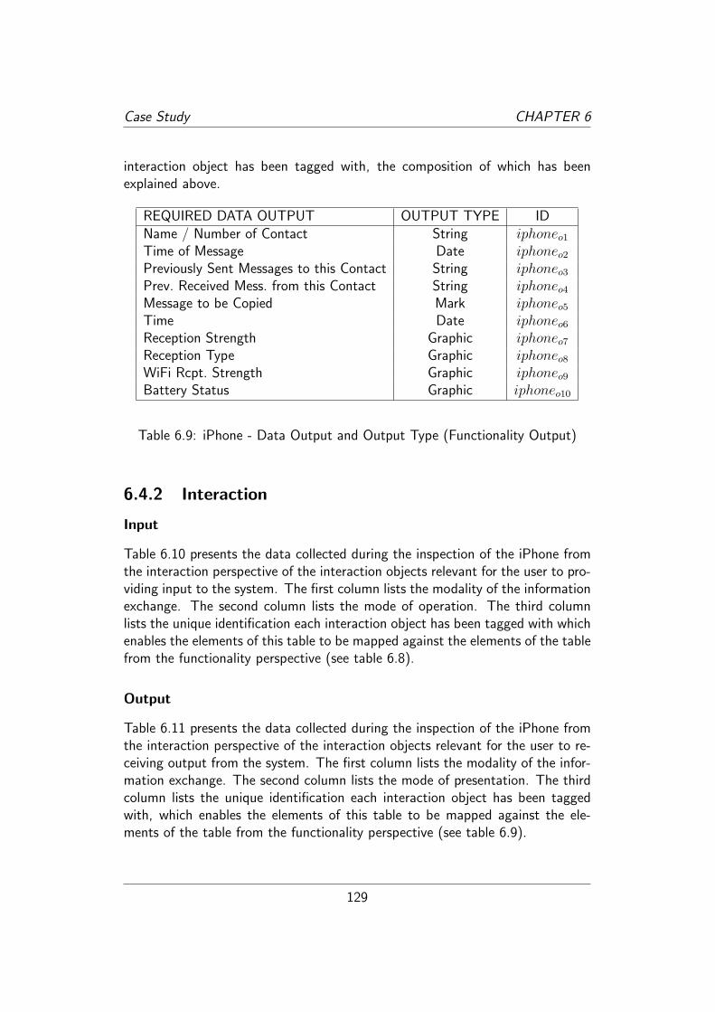
Case Study CHAPTER 6
interaction object has been tagged with, the composition of which has beenexplained above.
REQUIRED DATA OUTPUT OUTPUT TYPE IDName / Number of Contact String iphoneo1
Time of Message Date iphoneo2
Previously Sent Messages to this Contact String iphoneo3
Prev. Received Mess. from this Contact String iphoneo4
Message to be Copied Mark iphoneo5
Time Date iphoneo6
Reception Strength Graphic iphoneo7
Reception Type Graphic iphoneo8
WiFi Rcpt. Strength Graphic iphoneo9
Battery Status Graphic iphoneo10
Table 6.9: iPhone - Data Output and Output Type (Functionality Output)
6.4.2 Interaction
Input
Table 6.10 presents the data collected during the inspection of the iPhone fromthe interaction perspective of the interaction objects relevant for the user to pro-viding input to the system. The first column lists the modality of the informationexchange. The second column lists the mode of operation. The third columnlists the unique identification each interaction object has been tagged with whichenables the elements of this table to be mapped against the elements of the tablefrom the functionality perspective (see table 6.8).
Output
Table 6.11 presents the data collected during the inspection of the iPhone fromthe interaction perspective of the interaction objects relevant for the user to re-ceiving output from the system. The first column lists the modality of the infor-mation exchange. The second column lists the mode of presentation. The thirdcolumn lists the unique identification each interaction object has been taggedwith, which enables the elements of this table to be mapped against the ele-ments of the table from the functionality perspective (see table 6.9).
129

Case Study CHAPTER 6
MODALITY MODE OF OPERATION IDHaptic Virtual Button iphonei1
Haptic Virtual Button iphonei2
Haptic Virtual Button iphonei3
Haptic Virtual Button iphonei4
Haptic Virtual Button iphonei5
Haptic Button iphonei6
Equilibrioceptic Rotate 90◦ to Side iphonei7
Haptic Touch & Hold Message iphonei8
Haptic Switch Button iphonei9
Haptic Button iphonei10
Haptic Hold Down Button iphonei11
Haptic Rocker Button iphonei12
Haptic Home-Button + Powerswitch iphonei13
Table 6.10: iPhone - Modality and Mode of Operation (Interaction Input)
MODALITY MODE OF PRESENTATION IDVisual String iphoneo1
Visual String iphoneo2
Visual String iphoneo3
Visual String iphoneo4
Visual Color Change iphoneo5
Visual String in Topbar iphoneo6
Visual Graphic in Topbar iphoneo7
Visual Graphic in Topbar iphoneo8
Visual Graphic in Topbar iphoneo9
Visual Graphic in Topbar iphoneo10
Table 6.11: iPhone - Modality and Mode of Presentation (Interaction Output)
130

Case Study CHAPTER 6
6.4.3 Style
Input
Table 6.12 presents the data collected during the inspection of the iPhone fromthe style perspective of the interaction objects relevant for the user to providinginput to the system. The first column lists the color of the interaction object.The second column lists the unique identification each interaction object hasbeen tagged with which enables the elements of this table to be mapped againstthe elements of the table from the functionality and interaction perspective (seetable 6.8 and table 6.10).
COLOR IDGreengrey iphonei1
Greengrey iphonei2
White iphonei3
White iphonei4
Blue Glossy Gradient iphonei5
Black/Grey iphonei6
- iphonei7
Black String iphonei8
Silver Metallic iphonei9
Silver Metallic iphonei10
Silver Metallic iphonei11
Table 6.12: iPhone (Style Input)
Output
Table 6.13 presents the data collected during the inspection of the iPhone fromthe style perspective of the interaction objects relevant for the user to providinginput to the system. The first column lists the data input of the of the informationexchange. The second column lists the unique identification each interactionobject has been tagged with, which enables the elements of this table to bemapped against the elements of the table from the functionality and interactionperspective (see table 6.9 and table 6.11).
131

Case Study CHAPTER 6
COLOR IDWhite iphoneo1
Grey iphoneo2
Black iphoneo3
Black iphoneo4
White/Grey/Blue iphoneo5
Black iphoneo6
Blue / Light Blue iphoneo7
Blue iphoneo8
Blue iphoneo9
Adaptive Color iphoneo10
Table 6.13: iPhone (Style Output)
6.5 Comparison
The Reference Model for Interaction Oriented Systems can be helpful in, both,the analysis and synthesis of interaction oriented systems. While the synthesiswill not at all be part of this case study, the analysis comprises the description,evaluation, and comparison of interaction oriented system. The description oftwo scenes has been offered in the previous section, a very brief and personalevaluation will be offered as part of the conclusion of the case study (see 6.6).And the following section offers a comparison of the two scenes described above.
This comparison, also, is only a quantitative comparison while some qualitativeassessment from the author’s personal point of view is being provided in theconclusion of this thesis. While the benefit of a thorough comparison thus is notbeing provided in this thesis, the quantitative comparison offered here demon-strates how the Reference Model for Interaction Oriented Systems can be appliedas a tool for that, as it allows a detailed presentation of scenes, separated intothe domains of skills of functionality, interaction, and style related aspects.
6.5.1 Functionality
Input
Table 6.14 presents a selection of the data from the previous tables of the Pre’sfunctionality input (table 6.2), and the iPhone’s functionality input (table 6.8).The first entries up to the empty row of the table show those interaction objectson each device which provide the same functionality. The entries following afterthe empty row then present those interaction objects on each device, to which
132
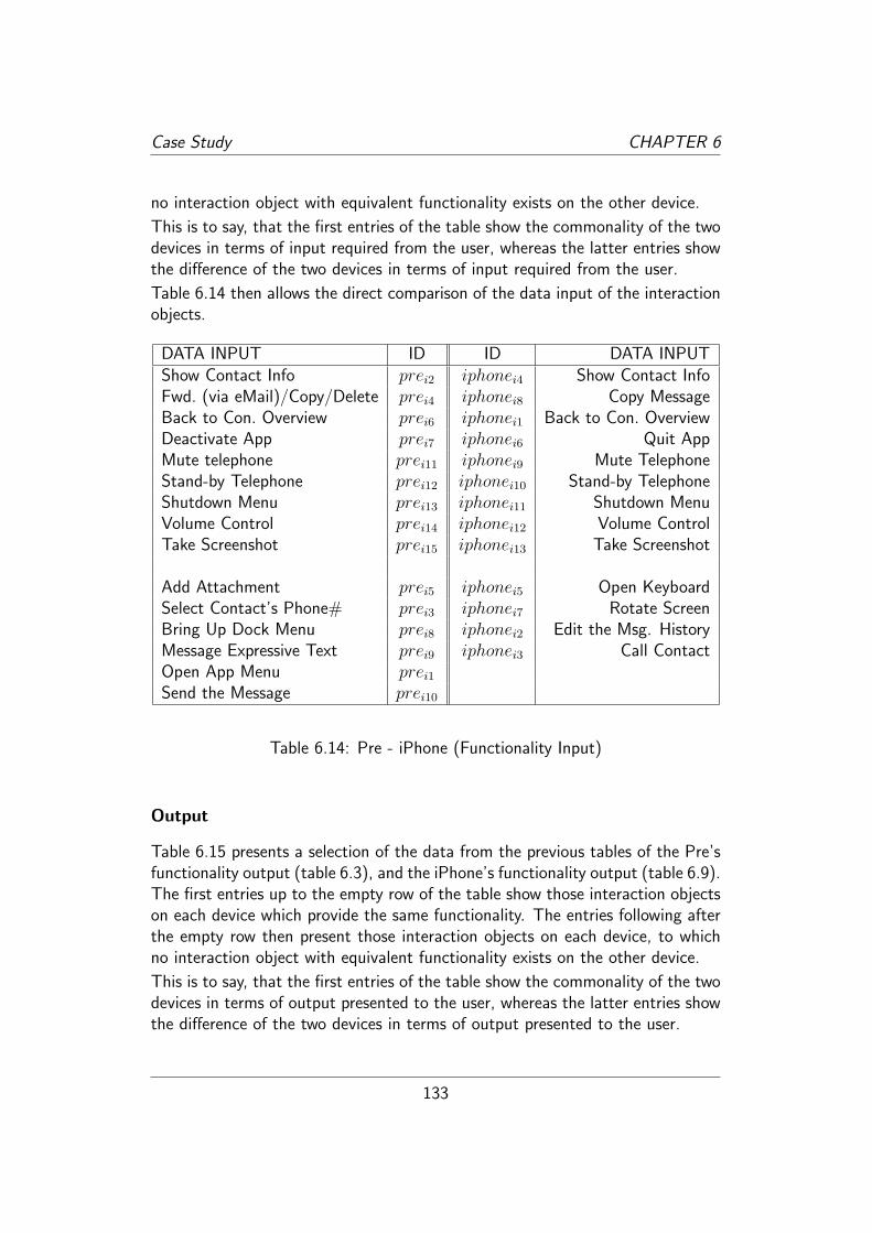
Case Study CHAPTER 6
no interaction object with equivalent functionality exists on the other device.
This is to say, that the first entries of the table show the commonality of the twodevices in terms of input required from the user, whereas the latter entries showthe difference of the two devices in terms of input required from the user.
Table 6.14 then allows the direct comparison of the data input of the interactionobjects.
DATA INPUT ID ID DATA INPUTShow Contact Info prei2 iphonei4 Show Contact InfoFwd. (via eMail)/Copy/Delete prei4 iphonei8 Copy MessageBack to Con. Overview prei6 iphonei1 Back to Con. OverviewDeactivate App prei7 iphonei6 Quit AppMute telephone prei11 iphonei9 Mute TelephoneStand-by Telephone prei12 iphonei10 Stand-by TelephoneShutdown Menu prei13 iphonei11 Shutdown MenuVolume Control prei14 iphonei12 Volume ControlTake Screenshot prei15 iphonei13 Take Screenshot
Add Attachment prei5 iphonei5 Open KeyboardSelect Contact’s Phone# prei3 iphonei7 Rotate ScreenBring Up Dock Menu prei8 iphonei2 Edit the Msg. HistoryMessage Expressive Text prei9 iphonei3 Call ContactOpen App Menu prei1
Send the Message prei10
Table 6.14: Pre - iPhone (Functionality Input)
Output
Table 6.15 presents a selection of the data from the previous tables of the Pre’sfunctionality output (table 6.3), and the iPhone’s functionality output (table 6.9).The first entries up to the empty row of the table show those interaction objectson each device which provide the same functionality. The entries following afterthe empty row then present those interaction objects on each device, to whichno interaction object with equivalent functionality exists on the other device.
This is to say, that the first entries of the table show the commonality of the twodevices in terms of output presented to the user, whereas the latter entries showthe difference of the two devices in terms of output presented to the user.
133
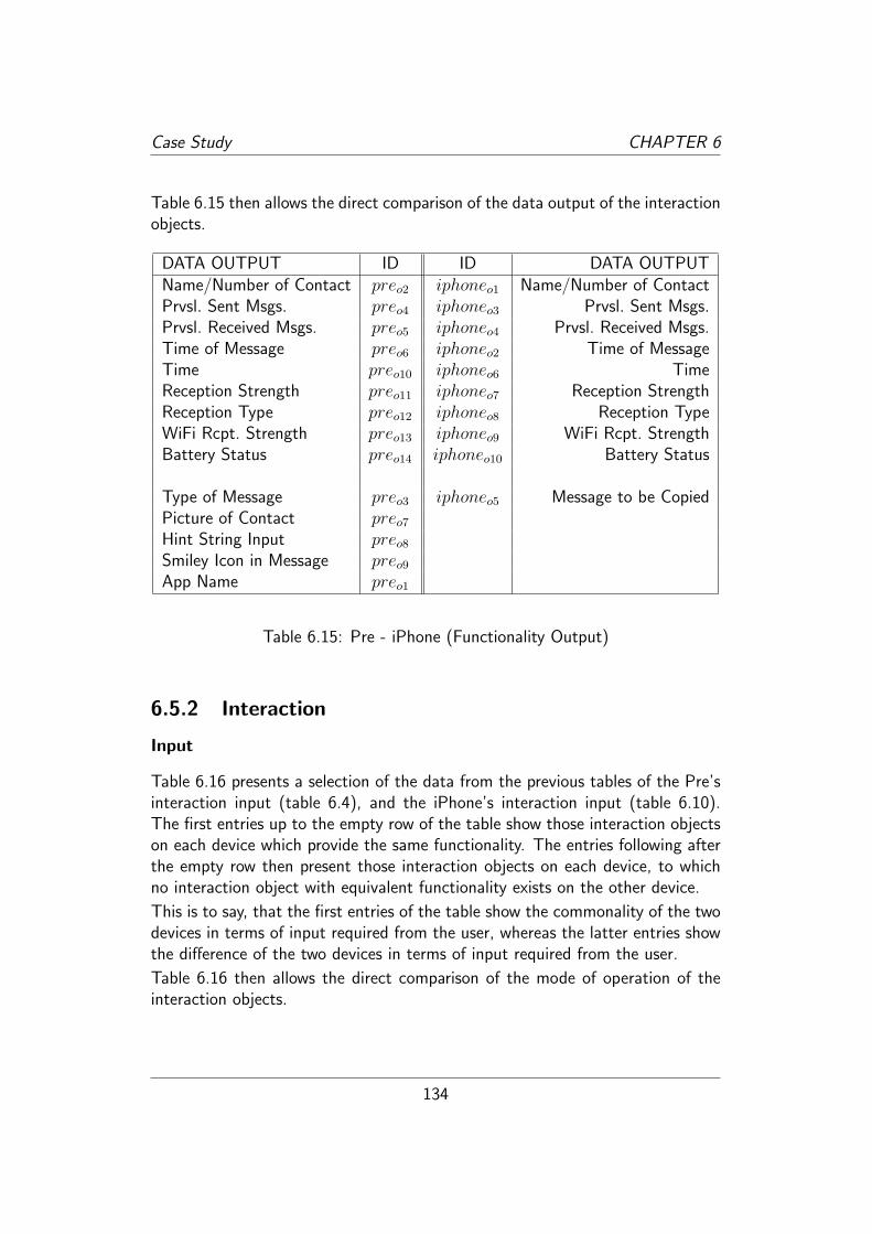
Case Study CHAPTER 6
Table 6.15 then allows the direct comparison of the data output of the interactionobjects.
DATA OUTPUT ID ID DATA OUTPUTName/Number of Contact preo2 iphoneo1 Name/Number of ContactPrvsl. Sent Msgs. preo4 iphoneo3 Prvsl. Sent Msgs.Prvsl. Received Msgs. preo5 iphoneo4 Prvsl. Received Msgs.Time of Message preo6 iphoneo2 Time of MessageTime preo10 iphoneo6 TimeReception Strength preo11 iphoneo7 Reception StrengthReception Type preo12 iphoneo8 Reception TypeWiFi Rcpt. Strength preo13 iphoneo9 WiFi Rcpt. StrengthBattery Status preo14 iphoneo10 Battery Status
Type of Message preo3 iphoneo5 Message to be CopiedPicture of Contact preo7
Hint String Input preo8
Smiley Icon in Message preo9
App Name preo1
Table 6.15: Pre - iPhone (Functionality Output)
6.5.2 Interaction
Input
Table 6.16 presents a selection of the data from the previous tables of the Pre’sinteraction input (table 6.4), and the iPhone’s interaction input (table 6.10).The first entries up to the empty row of the table show those interaction objectson each device which provide the same functionality. The entries following afterthe empty row then present those interaction objects on each device, to whichno interaction object with equivalent functionality exists on the other device.
This is to say, that the first entries of the table show the commonality of the twodevices in terms of input required from the user, whereas the latter entries showthe difference of the two devices in terms of input required from the user.
Table 6.16 then allows the direct comparison of the mode of operation of theinteraction objects.
134

Case Study CHAPTER 6
MODE OF OPERATION ID ID MODE OF OPERATIONVirtual Button prei2 iphonei4 Virtual ButtonVirtual Button prei4 iphonei8 Touch&HoldGesture (right to left) prei6 iphonei1 Virtual ButtonGesture (down to up) prei7 iphonei6 ButtonSlide Button prei11 iphonei9 Switch ButtonButton prei12 iphonei10 ButtonRocker Switch prei13 iphonei11 Rocker Switch
Virtual Button prei5 iphonei5 Virtual ButtonVirtual Button prei3 iphonei7 Rotate 90◦
Gesture(full down to up) prei8 iphonei2 Virtual ButtonKeyboard prei9 iphonei3 Virtual ButtonVirtual Button prei1
Key (Enter Key) prei10
Virtual Button prei10
Table 6.16: Pre - iPhone (Interaction Input)
Output
Table 6.17 presents a selection of the data from the previous tables of the Pre’sinteraction output (table 6.5), and the iPhone’s interaction output (table 6.11).The first entries up to the empty row of the table show those interaction objectson each device which provide the same functionality. The entries following afterthe empty row then present those interaction objects on each device, to whichno interaction object with equivalent functionality exists on the other device.
This is to say, that the first entries of the table show the commonality of the twodevices in terms of output presented to the user, whereas the latter entries showthe difference of the two devices in terms of output presented to the user.
Table 6.17 then allows the direct comparison of the mode of operation of theinteraction objects.
6.5.3 Style
6.5.4 Input
Table 6.18 presents a selection of the data from the previous tables of the Pre’sstyle input (table 6.6), and the iPhone’s style input (table 6.12). The first entries
135

Case Study CHAPTER 6
MODE OF PRES. ID ID MODE OF PRES.String in Headerpill preo2 iphoneo1 String in HeaderboxExpressive Text Over Col. BG preo4 iphoneo3 String Over Colored BGExpressive Text Over Col. BG preo5 iphoneo4 String Over Colored BGString preo6 iphoneo2 StringString preo10 iphoneo6 StringGraphic in Topbar preo11 iphoneo7 Graphic in TopbarGraphic in Topbar preo12 iphoneo8 Graphic in TopbarGraphic in Topbar preo13 iphoneo9 Graphic in TopbarGraphic in Topbar preo14 iphoneo10 Graphic in Topbar
String in Drop-Down Button preo3 iphoneo5 Color ChangePicture in Message preo7
String in Empty Textfield preo8
Icon in Message Text preo9
String in Drop-Down Button preo1
Table 6.17: Pre - iPhone (Interaction Output)
up to the empty row of the table show those interaction objects on each devicewhich provide the same functionality. The entries following after the empty rowthen present those interaction objects on each device, to which no interactionobject with equivalent functionality exists on the other device.
This is to say, that the first entries of the table show the commonality of the twodevices in terms of input required from the user, whereas the latter entries showthe difference of the two devices in terms of input required from the user.
Table 6.18 then allows the direct comparison of the color of the interactionobjects.
Output
Table 6.19 presents a selection of the data from the previous tables of the Pre’sstyle output (table 6.7), and the iPhone’s style output (table 6.13). The firstentries up to the empty row of the table show those interaction objects on eachdevice which provide the same functionality. The entries following after theempty row then present those interaction objects on each device, to which nointeraction object with equivalent functionality exists on the other device.
This is to say, that the first entries of the table show the commonality of the twodevices in terms of output presented to the user, whereas the latter entries show
136

Case Study CHAPTER 6
COLOR ID ID COLORLight Grey Gradient prei2 iphonei4 WhiteBlack String prei4 iphonei8 Black StringBlack String prei6 iphonei1 GreengreyBlack prei11 iphonei9 Silver MetallicBlack prei12 iphonei10 Silver MetallicBlack prei13 iphonei11 Silver Metallic
Light Grey Gradient prei5 iphonei5 Blue Glossy Gradient(Picture) prei7 iphonei3 WhiteBlack prei8 iphonei2 GreengreyLight Grey prei9 iphonei6 Black/GreyLight Grey prei1
Black prei10
Dark Grey prei10
Black String in Blue Bubble prei3
iphonei7 -
Table 6.18: Pre - iPhone (Style Input)
the difference of the two devices in terms of output presented to the user.
Table 6.19 then allows the direct comparison of the color of the interactionobjects.
6.6 Conclusion
The execution of the case study served three purposes. The first purpose wasto demonstrate a proof of concept that the Reference Model for Interaction Ori-ented Systems can actually be applied in a practical way. The second purpose,akin to the first, was to demonstrate, that the Reference Model for InteractionOriented Systems fulfills the requirements defined by the hypothesis. The thirdpurpose was to critically examine the Reference Model for Interaction OrientedSystems and generate informative feedback on its structure and model elements,effectively helping during the creation and leading to the improvement of the Ref-erence Model for Interaction Oriented Systems. That feedback will be discussedin the following subsection. The other two aspects will follow afterwards.
137

Case Study CHAPTER 6
COLOR ID ID COLORWhite preo2 iphoneo1 WhiteBlack preo4 iphoneo3 BlackBlack preo5 iphoneo4 BlackGrey preo6 iphoneo2 GreyWhite preo10 iphoneo6 BlackLight Grey / Dark Grey preo11 iphoneo7 Blue / Light BlueWhite preo12 iphoneo8 BlueWhite preo13 iphoneo9 BlueWhite preo14 iphoneo10 Adaptive Color
Grey preo3 iphoneo5 White/Grey/BlueWhite Frame preo7
Light Grey preo8
Yellow preo9
White preo1
Table 6.19: Pre - iPhone (Style Output)
6.6.1 Feedback for the Reference Model for InteractionOriented Systems
This subsection presents elements that were created as a direct result of the con-duction of the case study. During the case study some fundamental shortcomingsof the model were being realized and subsequently fixed. This demonstrates thatthe case study added a much needed practical view on the Reference Model forInteraction Oriented Systems which, up to that point, had been created basedon theoretical and analytical grounds alone.
The elements refined or added to the Reference Model for Interaction OrientedSystems caused by discoveries during the case study are being listed here. Itshould demonstrate, both, that creating a model that aims to be of practical usefrom only a theoretical perspective can fall short of its intention, and that thecase study has been more than only a means to show case the Reference Modelfor Interaction Oriented Systems but was actually a vital part in the reiterativeprocess of creating the model.
Scene
An absolutely crucial result of the case study in terms of the refinement of theReference Model for Interaction Oriented Systems was the addition of the “scene”
138
Case Study CHAPTER 6
element (and the “scene trigger” subsequently). The scene was not part of themodel at the beginning of the execution of the case study, albeit the case studywas being conducted in such a manner that already adhered to the concept ofthe scene, namely inspecting all interaction elements available in that particular“snapshot” of the application and stopping whenever the “snapshot” changednoticeably. After a while the question crystallized as to what exactly constitutesand justifies the limit of the inspection during this case study. Pondering thisquestion it became clear that it had to be possible to describe a certain “state”of an application in order to be able to provide a description of the interactionobjects in that “state”. This eventually lead to the concept of the scene (see page72) and subsequently to the creation of the scene trigger, which was stringentlynecessary after the scene element was created. The scene then also enabled theprecise definition of an interaction oriented system (see page 71) which effectivelyprovided a fundamentally required completion of the model.
Mode of Operation and Mode of Presentation
At the initial execution of the case study, the Reference Model for Interaction Ori-ented Systems did not include the elements “Mode of Operation” and “Mode ofPresentation”. During the case study then, when trying to describe the inspectedinteraction objects of the scene from the interaction perspective, it became im-mediately obvious that the model was incomplete for the purpose of producinga description of practical value of an interaction oriented system. Describingonly the modality of an interaction object seemed to stop too early regarding thespecific “feel” of an interaction object, as obviously an interaction object that ismerely described as being a visual one still leaves a huge array of possibilities asto exactly how that interaction object appears.
This blatantly apparent shortcoming of the descriptive power of the ReferenceModel for Interaction Oriented Systems was corrected by introducing the twomodel elements “Mode of Operation” and “Mode of Presentation” which nowenabled the modeler to precisely capture, not only the generic modality of aninteraction object, but also the specificity of an interaction object’s “interactive-ness” with the user.
Equilibrioceptic Interaction
The element of equilibrioceptic interaction was added to the model during thediscovery of the possibility to rotate the iPhone in order to rotate the screen.While several modalities are being included as stubs (for example the gustatorymodality), this modality may have escaped that collection had it not been for
139

Case Study CHAPTER 6
the actual occurence in the iPhone’s scene.
Minimum Value and Maximum Value
Another, although indirect, result of the case study was the moving of the modelelements “Minimum Value” and “Maximum Value” from the functionality per-spective, where they were initially contained, into the foundation. As it initiallyappeared that those two aspects were purely functionality related that view hadto be corrected as it was realized that the fact that a minimum and maximumvalue are present very much influences the choices made regarding the interactionand style of that element. Should an interaction object be restricted by either orboth, a minimum or maximum value this had to be made available to all threeperspectives. Good examples of the different interaction with a restricted inputvalue and an unrestricted input value are for example a round turning knob anda slider. Where the round turning knob could be used to adjust an unrestrictedvalue, the slider inherently has a minimum (the lowest end) and a maximum (thehighest end) value it restricts the user to.
The situation that triggered this realization was the inspection of the “messagetype” virtual button on the Pre, where a list of message types is being presented.Pondering the presentation of this list caused the realization that an existing min-imum and maximum value (or the non-existence thereof respectively) definitelyinfluences this decision. As the minimum and maximum value where then movedinto the foundation, the selection element followed, as the selection element justdescribes the coexistence of, both, a minimum and maximum value.
6.7 Evaluation of the Case Study
The evaluation of the case study is being broken up into two parts. The firstpart concentrates on the two scenes and by providing some evaluating thoughtsdemonstrates how the Reference Model for Interaction Oriented Systems opensup the space for the analysis of interaction oriented systems. That part, however,does not claim to provide a particularly deep and insightful evaluation but merelypresents the author’s personal thoughts on the two scenes. The second partconcentrates on the evaluation of the Reference Model for Interaction OrientedSystems after the case study as a practical appliance of the model and proof ofconcept has been concluded.
140

Case Study CHAPTER 6
6.7.1 Evaluation in Regard to the Inspected Scenes
This is a rudimentary evaluation of the data collected about the scenes duringthe case study that was being conducted as part of this thesis. Its purpose isto merely demonstrate the fact that such an evaluation can be done based onthe description of an interaction oriented systems by using the model elementsprovided by the Reference Model for Interaction Oriented Systems.
Comparison of the Pre’s and iPhone’s Scene
When comparing the two scenes with one another the following observations canbe made. The Pre provides a greater amount of functionality which can be easilyrecognized through the amount of input and output functionality available to theuser as presented by tables 6.2, 6.3, 6.8, and 6.9. This can be argued as, both,a positive or negative aspect of the Pre’s app. The positive point of view wouldargue, that the app is providing more functionality to the user, the negative pointof view would argue, that the iPhone focuses on the essential and truly importantfunctionality of such an app. Only an extensive field study including a statisticallyrelevant number of participating test users could give substance to either claim.The author is inclined to see this as a positive aspect of the Pre’s app. As forexample the inclusion of little graphical emoticons in the message text add anincreased element of personality to the message text absent from the iPhone’spresentation of the messages. And the absence of ability to send an attachmentwith a message seems quite inexcusable for a device like the iPhone.
A pivotal difference, however, is the variety of modes of operations on each de-vice (see tables 6.4 and 6.10). With the exception of the equilibrioceptic input ofrotating the device on the iPhone, all other modes of operation consist of virtualor real buttons. Whereas the Pre adds a variety of gestures to the “mode ofoperation”-set, along with the coexistence of real keys on the keyboard and vir-tual buttons on the interface. The author believes that, while both these modesof operation add an element of convenience and increased accessibility to thefunctionality of the app when known well, they probably are a source of confu-sion for the novice user of the device. Here, the need of an instructive tutorialor usually dreaded manual becomes apparent, a circumstance the iPhone suc-cessfully circumvents by reducing the mode of operations to a very homogenousarray of possibilities.
A negative aspect that was spotted during the case study was the discovery oflack of feedback on one of the Pre’s interaction objects. This aspect is actuallynot included in the tables of the case study, as “feedback” was not made a columnin the tables (as all elements except for one provided feedback it would have beena rather unimpressive column and the lack of feedback on that one element is
141

Case Study CHAPTER 6
being covered here now). The element in question is the interaction object prei1,the virtual button to open the app menu. Which when touched (activated) doesnot give any sort of feedback that this activation has been registered by the app.All other interaction objects provide this feedback by changing their color whilebeing touched, but this element does nothing and the user just has to wait themoment to find out whether he managed to hit the especially small virtual buttonin the top left corner of the screen. During moments of increased backgroundactivity – which can happen quite often on the Pre as it allows for the userto have several apps running simultaneously (a feature desperately missing onthe iPhone) – it can take up to a few seconds before the actual result of theactivating of that interaction object appears, namely, the showing of the appmenu. In these situations the lack of feedback is particularly bothersome as notseeing the app menu showing up right away typically leads the user (including theauthor of this thesis) to the repeated touching of that virtual button which then,once the device processes the queued up input, results in the quick succession ofopening, closing, opening, and closing of the app menu. This is such a ridiculousoversight on the side of Palm that the author can only speculate that it must havesimply been missed during the testing of the device. Providing feedback on theuser’s interaction with the system is one of the most fundamental and simplisticrules of good interface design – and not without reason one of Shneiderman’s“golden rules”. The positive aspect of this usability blooper by Palm, however,is that it demonstrates the Reference Model for Interaction Oriented Systems’ability to discover the aspect of provided feedback (or lack thereof) quite aptly.The author is grateful to the inattentive user-interface tester in Palm’s developerteam for this possibility.
And speaking of app menus: An interesting aspect that the case study exposedwas the lack of an app menu in the iPhone’s app. This signifies a difference inphilosophy regarding apps on Palm’s and Apple’s side. While the app in the Prewith its app menu works similar to an application on a desktop computer, byproviding a menu in which, for example, the preferences can be set, the app inthe iPhone works more like a small, completely specialized and flat7 application.The immediate result of this different approach is that the iPhone does not haveto deal with the layout of pull-down menu structures and the clutter on the screencaused by this. While certainly a change to the approach how a user interactswith an application, the author believes that the iPhone’s approach here seemsmore appropriate to the environment of contemporary smartphones.
A peculiar fact, then, was the discovery of the user actually not being able toenter any message text at the iPhone’s scene that was being inspected. Asthe iPhone is a purely “virtual keyboard” device (whereas the Pre provides a
7In terms of uncomplex and accessible.
142

Case Study CHAPTER 6
real keyboard that can be slid out from the device) and at the scene no virtualkeyboard is being presented, it is impossible for the user to enter text. Applesolves this in a clever way by providing a button at the bottom of the screenthat looks like a textfield and another graphic that looks like a button to theright of it (see figure 6.1). This actually is not a textfield, however. Rather thewhole area is a virtual button that when tapped causes the virtual keyboard toslide up from the bottom of the screen now enabling the user to enter text. Thecleverness of this method is the fact that the commonly known behavior of atextfield is to blink a text-cursor when the textfield is ready to receive input. Asthe textfield on the iPhone does not show such a blinking cursor, the user wantsto “activate” the textfield and taps into it, effectively clicking on a virtual buttonin disguise. The following effect of the virtual keyboard appearing is not partof the scene that was being inspected, however, and thus can only be includedhere. The author believes that it very nicely shows the analytical power providedby using the Reference Model for Interaction Oriented Systems.
Another difference between the iPhone’s and the Pre’s app in the inspected sceneis that the iPhone clearly indicates where the user can navigate “back” to, byincluding the description in the virtual button (see interaction object iphonei1).The equivalent functionality of navigating back to the conversation overview istriggered in the Pre’s app by the globally available gesture “right to left” (seeinteraction object prei6). This, however, does not provide the user with a senseof exactly where he can and will navigate “back” to. A minor drawback only,but one discovered during the description of the scene by utilizing the ReferenceModel for Interaction Oriented Systems and thus a drawback worth mentioning.
This concludes the author’s brief evaluation of the two scenes described by us-ing the Reference Model for Interaction Oriented Systems. Obviously a morequalified evaluation would be possible, but this realization is exactly the purposeof this evaluation: to demonstrate the Reference Model for Interaction OrientedSystems’ ability to provide methodological ground for the analysis and evaluationof existing interaction solutions.
6.7.2 Evaluation in Regard to the RM-IOS
The research questions underlying the case study were presented in the beginningof this chapter (see page 112) and this evaluation must now answer to them.
Policy of Separation of Concern
The first research question, whether the Reference Model for Interaction OrientedSystems supports the descriptive modeling of an interaction oriented system while
143

Case Study CHAPTER 6
incorporating a policy of separation of concern regarding the different domainsof skill and knowledge required during the user interface development processcan be answered affirmatively: The case study has shown that the appliance ofthe Reference Model for Interaction Oriented Systems during the description ofan interaction oriented system is feasible and produces a description of practicalvalue.
The policy of separation of concern is inherent to the structure of the ReferenceModel for Interaction Oriented Systems and its completeness in regard to theuser interface development process has already been confirmed during the devel-opment of the model (see chapter 4). However, that confirmation was from atheoretical point of view while the case study now provided the confirmation froma practical point of view. Inspecting the tables offered in the preceding section ofthis chapter a clearly realized policy of separation of concern can be observed asthe tables presenting the data collected during the inspection of the scene fromeach perspective primly observes the distinctly different domains of skill eachperspective in the reference model for interaction oriented system represents.
Another important aspect of a successful policy of separation of concern is theindependence of each perspective from one another. The case study has shownthat the Reference Model for Interaction Oriented Systems allows for the de-scription of an interaction oriented system from three perspectives independentlyfrom one another.
The combination of these two just described aspects constitutes a successfulrealization of a policy of separation of concern by the Reference Model for In-teraction Oriented Systems. This policy of separation of concern was one of therequirements stated in the hypothesis that the Reference Model for InteractionOriented Systems verifiably fulfills.
Provision of Methodological Ground
The second research question, whether the Reference Model for Interaction Ori-ented Systems provides methodological ground for the analysis and evaluation ofexisting interaction solutions can also be answered affirmatively: The case studyhas shown that the description of an interaction oriented system through themodel elements provided by the Reference Model for Interaction Oriented Sys-tems resulted in a detailed, exposing view on the described interaction orientedsystem.
This view then allowed for further analysis and evaluation of the described systemwhich has been provided in a rudimentary form in subsection 6.7.1.
The humble quality of the analysis and evaluation given there is only founded inthe humble abilities of the author to provide such an analysis and evaluation for
144

Case Study CHAPTER 6
which expert knowledge in the respective fields is required. The fact that suchanalysis and evaluation was being enabled by the use of the Reference Model forInteraction Oriented Systems to describe an interaction oriented system, however,remains untouched by just acknowledged curtailment.
145

146
Chapter 7
Conclusion
This chapter presents the contributions made by this thesis and offers a sug-gestion of potential future works that may extend this thesis or build on top ofit.
7.1 Summary of Contributions
This dissertation’s contribution is mainly made to the field of engineering of hu-man computer interaction. The Reference Model for Interaction Oriented Sys-tems introduced here enables the interdisciplinary collaboration of three impor-tant areas of skill on a user interface development project, namely, the disciplineof software development, the discipline of human computer interaction design,and the related disciplines of artistic design. This collaboration is being enabledby realizing a policy of separation of concern in the structure of the model, thus,allowing the expertise from those disciplines to be brought together while drawingthe border lines of responsibility for each.
The contribution of this thesis can then be viewed from two different perspectives:
1. From the analytical perspective
2. From the synthetical perspective
The following sections will present the contributions made by this thesis in regardto these two perspectives.
7.1.1 Contributions - From the Analytical Perspective
The analytical perspective of software development comprises the description,comparison, verification, and evaluation of systems. The analytical perspective
147

Conclusion CHAPTER 7
is one on an existing system which is the object of interest.
Description
In the domain of software development a description of a system is a model of thesystem that serves the purpose of providing an objective depiction of the system.In order for a description to be of practical value, it must be anchored in avocabulary commonly accessible by all stakeholders involved. Such a vocabularyis the necessary premise to avoid ambiguities and provide mental models of theconcepts contained within it. The Reference Model for Interaction OrientedSystems provides such a vocabulary for the description of interaction orientedsystems from three perspectives which can be conjoined in the element of theinteraction object.
Comparison
Two or more systems can be compared with one another, however, the basis for ameaningful comparison is an objective and uniform description. As just previouslyshown, the Reference Model for Interaction Oriented Systems provides the meansfor producing such a description, and thus, in consequence provides the basis forthe comparison of two or more interaction oriented systems in those aspectscaptured by the Reference Model for Interaction Oriented Systems.
Verification
Verification of a system is a means to ensure that the requirements described ina specification of a system are being met by the system and is a fundamentallyimportant aspect in the completion, i.e. delivery and acceptance, of a system.The Reference Model for Interaction Oriented Systems can be used as a tool forverification by checking the system for the fulfillment described through elementsof the Reference Model for Interaction Oriented Systems.
Evaluation
Evaluation is the normative revision of a system. When a system has been de-scribed, the Reference Model for Interaction Oriented Systems provides a frame-work for an evaluation to be drawn from the description.
148

Conclusion CHAPTER 7
7.1.2 Contributions - From the Synthetical Perspective
The synthetical perspective of software development comprises the specificationand modeling for the purpose of building of a system. The synthetical per-spective is one on a system S that does not yet exist. Effectively saying, that Smerely exists in the conception of the stakeholders and thus must be externalizedappropriately.
Specification
Specification is a certain kind of description, namely, a binding description ofa system yet to be built that is typically set during the early stages of thedevelopment cycle and which allows the customer to express his wants and needsfor the system, and allows the developer to estimate the time and effort neededto be put into the development of such a system, and in turn give an estimationof the cost to be expected. The reference model for interaction oriented systemprovides an interdisciplinary vocabulary for the realization of such a specification.
7.1.3 Modeling
The modeling of a system is a process that is prevalent throughout both stages ofsystem development, i.e. the stages of analysis and the stages of synthesis. Thereference model for interaction oriented system provides a modeling frameworkfor modeling a system which allows for the reduction of complexity in regard tothat particular perspective and thus results in structural clarity helpful for thedescription and perception of the modeled interaction oriented system.
Furthermore, the Reference Model for Interaction Oriented Systems includes cer-tain aspects of human computer interaction in a structured manner, bringingsome implicit aspects from the interpretation of usability guidelines to the ex-plicit realm of modeling. By identifying some elements which do not have to besurrendered to merely the talent in human computer interaction of the respectivedevelopers involved in the development process the Reference Model for Inter-action Oriented Systems provides a way to repeat the successful usability andinteraction design of certain systems.
Also, through the tripartite nature of the Reference Model for Interaction Ori-ented Systems, the model provides a gateway of model-based communicationbetween those experts from the domains of functionality, interaction, and style.
149

Conclusion CHAPTER 7
7.1.4 Internal Validation
To validate the Reference Model for Interaction Oriented Systems proposed inthis thesis it must be analytically assessed against a set of selected criteria. Thosecriteria are given in the hypothesis and are the requirements of this model. Thissection inspects the fulfillment of those requirements. The requirements were:
1. Mirroring the separated domains of skill, knowledge, and expertise requiredto cope with the needs of successful interaction design and implementation.
2. Covering the many aspects to be dealt with in successful interaction designand implementation.
3. Providing methodological ground for analysis and evaluation of existinginteraction solutions.
4. Providing the basis for proper organization of development teams for in-teraction design and implementation.
5. It can be justified by what is known about successful interaction designand implementation endeavors.
These points will now be discussed from a rational point of view in an attemptto provide an internal validation of the fulfillment of these goals.
1. The Reference Model for Interaction Oriented Systems incorporates a tri-partite structure that reflects the identified domains of skill, knowledge, andexpertise as fundamental perspectives on contemporary interaction orientedsystem. These three domains and the segmentation of the model into thesehave been built on the identification of aspects relevant in contemporaryinteraction oriented system, the identifying of associational attributes inthese aspects, and the resulting domains of skill and knowledge realizableby dividing the whole of aspects at the least connected borders (see chapter4).
2. The Reference Model for Interaction Oriented Systems provides an exten-sive vocabulary for the modeling of interaction oriented systems. Theseaspects have been gathered by identifying the core concepts present in theguides and recommendations of accredited experts in the field of humancomputer interaction and usability. By making these aspects readily avail-able they are being raised into the field of awareness of those involvedin, both, the synthetic processes, as well as the analytical processes ofinteraction oriented systems.
150

Conclusion CHAPTER 7
3. In the domain of software development a methodology is a framework forproviding structured and reproducible processes to analyzing or synthesiz-ing a system. By offering the means to break a system down into itselements (in regard to the domain of functionality, interaction, and style)the perceived complexity of a system can be reduced and the system can beapproached from those perspectives. This, in theory, provides methodolog-ical ground for the analysis and evaluation of interaction solutions. (Thecase study offers a much more tangible external validation of this aspect.)
4. Akin to the preceding point, the disassembling of a system in a well definedand structured way based on a policy of separation of concerns which inturn has been deduced from the involved areas of expertise and know-ledge, offers the possibility to organize development teams accordingly. TheReference Model for Interaction Oriented Systems provides the necessaryperspective based approach for realizing such organization by incorporatinga perspective based structure.
5. The analytical process of developing the Reference Model for InteractionOriented Systems has been anchored in the best practice advice and guidesoffered by accredited usability experts, exemplary, on the “eight goldenrules of user interface design” by Shneiderman. This ensures the inclusionof currently available knowledge about successful interaction design andimplementation endeavors.
7.1.5 External Validation
The external validation of the goals set in the hypothesis for the Reference Modelfor Interaction Oriented Systems has been provided in the case study conductedfor this thesis (see chapter 6). The external validation had to be restricted tocertain goals, however, as some goals, especially those regarding the usefulnessof the Reference Model for Interaction Oriented Systems for the synthesis ofinteraction oriented systems could not have been carried out in a significantlymeaningful way during the course of this thesis. The empirical justification for thepotential contribution of the Reference Model for Interaction Oriented Systemsin regard to the synthesis of interaction oriented systems is a matter outside thescope of this thesis and could only be provided by actually employing the modelin follow up projects. However, some aspects have been successfully backed bythe findings of the case study and those will be presented here. The following listrefers to the points listed above which are the goals formulated in the hypothesis.
1. The conduction of the case study has shown that the Reference Model forInteraction Oriented Systems provides a practical policy of separation of
151

Conclusion CHAPTER 7
concern which realizes the required realization of such a policy as set outin the hypothesis.
2. The conduction of the case study has shown that the scenes of the systemsthat were being subjected to the description produced by the application ofthe Reference Model for Interaction Oriented Systems covered many of theaspects of those systems in regard to the three perspectives incorporatedby the model. The descriptions presented in section 6.3 and following offera description of the system by systematically presenting the aspects of thesystem from each of the three perspectives.
3. As briefly covered in the case study, the initial description produced duringthe case study provided a methodological ground for the following evalua-tion of the two scenes. The briefness of the evaluation is only owed to thefact that the author of this thesis can not provide a more in-depth eval-uation, but it was demonstrated that an extensive evaluation could havebeen provided, given the required expertise for such an evaluation had beenavailable.
4. This aspect could not have been covered during the conduction of thecase study for this thesis, as it would have required the inclusion of a largedevelopment team in order to verify this point. Thus, only the internalvalidation, i.e. the analytically based assumption of this aspect, can begiven (see above).
5. This aspect, too, is an aspect that relies rather on an internal validationthan an external one, and so this point has been validated above by show-ing that the reference model for interaction oriented system is based onthe knowledge of accredited user interface engineering experts and theircontemporary advice and guidance.
The reasoning behind these statements can be found in the conclusion of thecase study in section 6.6.
7.2 Future Work in Prospect
Part of the quality of a scientific contribution as being made by such a thesishere can be found in the preceding work it builds on and the future work it leadsto. The preceding work this thesis is built upon has been presented partly inchapter 2 and mostly in chapter 3. This section now aims to provide possiblefuture work that could be build on top of this thesis.
152

Conclusion CHAPTER 7
� The synthesis of an interaction oriented system based on the referencemodel for interaction oriented system is not part of this thesis but wouldbe an interesting prospect. It is thinkable for a development methodologyto be anchored in the reference model for interaction oriented system,utilizing its descriptive power during the course of initial system conception,description, and possibly specification. A simple proof of concept of thiscould be provided during the course of a master thesis.
� It would be an interesting verification of and promising possibility regardingthe extension of the Reference Model for Interaction Oriented Systemsto try to describe a guideline available to system developers such as forexample Apple’s human interface guideline [Inc06] with the vocabulary ofthe Reference Model for Interaction Oriented Systems. Such a projectwould verify the expressive power of the Reference Model for InteractionOriented Systems and detect shortcomings and needs for extensions in astructured and analytical way.
� As just mentioned, the reference model for interaction oriented systemshould be extended, especially the style perspective, as that one is clearlythe weakest of the three perspectives, owed to the author’s lack of expertisein the area of artistic design. A sensible first approach here seems to bethe cooperation with someone with appropriate knowledge in the field ofartistic design and try to work that knowledge into the style perspective ofthe Reference Model for Interaction Oriented Systems.
� Information science is a science of models and a plethora of models existfor this discipline. A very interesting future work would be the investiga-tion of the possibility of combining the Reference Model for InteractionOriented Systems with other models prevalent in the domain of softwaredevelopment for human computer interaction. Explicit examples could bethe conjunction of the Reference Model for Interaction Oriented Systemswith the GOMS model, or UML activity diagrams as those are two ex-amples of models covering completely different aspects of modeling in thedomain of software development for human computer interaction.
� A possible future work of grand proportion would be the implementationof an integrated developing environment (IDE) based on the principles ofmodel driven development (MDD) with the reference model of interactionoriented systems as a basis. This would require considerable resources in,both, time and expertise needed.
� An obvious future work would be the extension of the case study presentedhere to the description of not only two scenes of an app, but two complete
153

Conclusion CHAPTER 7
apps. The feedback to be had from such an extensive case study shouldprovide valuable inspiration to the further improvement of the ReferenceModel for Interaction Oriented Systems.
Reviewing the possible future work with and for the Reference Model for In-teraction Oriented Systems just given illustrates the space of potential researchunlocked by this thesis.
It is the personal opinion of the author of this thesis that the main contributionof this thesis is the provision of a sound fundament that can be extended toprovide a truly meaningful improvement in the practical realm of the domain ofhuman computer interaction.
7.3 Scientific Challenges
The main scientific challenge during the preparation of this thesis was the processof structuring the findings during the conducted research into a sensible modelthat promises to be of practical value while fulfilling the goals initially set out forit.
In hindsight many of the decisions and structural characteristics of the ReferenceModel for Interaction Oriented Systems seem self-evident and possibly provokea perception of simplicity of the model. Should this perception really be invokedin the reader, then the author believes a crucially important element of successhas been achieved, as probably nothing is more refraining from engaging in amodel than a complicated and convoluted appearance. The structural clarityand apparent simplicity of the reference model for interaction oriented system -that the author believes has been achieved - has been a long journey that waspaved with critical analysis, challenging every decision made, restructuring themodel many times over and subjecting it as often as possible to the eyes of thoseunfamiliar with the actual model itself but the ability to provide critical feedback.
Another challenge for the author was the accumulation of knowledge in thethree perspectives to a point sufficient enough of mirroring their essence in theperspectives of the model.
Finally, the author would like to thank the reader for the time invested in readingthis document; if nothing else obviously at least this part.
154

155

156

Appendix A
Appendix
A.1 Shneiderman’s Eight Golden Rules Of Inter-face Design
1. Strive for consistencyThis rule is the most frequently violated one, but following it can be trickybecause there are many forms of consistency. Consistent sequences of ac-tions should be required in similar situations; identical terminology shouldbe used in prompts, menus, and help screens; and consistent color, layout,capitalization, fonts, and so on should be employed throughout. Excep-tions, such as required confirmation of the delete command or no echoingof passwords, should be comprehensible and limited in number.
2. Cater to universal usabilityRecognize the needs of diverse users and design for plasticity, facilitatingtransformation of content. Novice-expert differences, age ranges, disabil-ities, and technology diversity each enrich the spectrum of requirementsthat guides design. Adding features for novices, such as explanations, andfeatures for experts, such as shortcuts and faster pacing, can enrich theinterface design and improve perceived system quality.
3. Offer informative feedbackFor every user action, there should be system feedback. For frequent andminor actions, the response can be modest, whereas for infrequent andmajor actions, the response should be more substantial. Visual presentationof the objects of interest provides a convenient environment for showingchanges explicitly.
4. Design dialogs to yield closure
157

Appendix CHAPTER A
Sequences of actions should be organized into groups with a beginning,middle, and end. Informative feedback at the completion of a group ofactions gives operators the satisfaction of accomplishment, a sense of relief,the signal to drop contingency plans from their minds, and a signal toprepare for the next group of actions. For example, e-commerce web sitesmove users from selecting products to the checkout, ending with a clearconformation page that completes the transaction.
5. Prevent errorsAs much as possible, design the system such that users cannot make seriouserrors; for example, gray out menu items that are not appropriate and donot allow alphabetic characters in numeric entry fields. If a user makes anerror, the interface should detect the error and offer simple, constructive,and specific instructions for recovery. For example, users should not haveto retype an entire name-address form if they enter an invalid zip code,but rather should be guided to repair only the faulty part. Erroneousactions should leave the system state unchanged, or the interface shouldgive instructions about restoring the state.
6. Permit easy reversal of actionsAs much as possible, actions should be reversible. This feature relievesanxiety, since the user knows that errors can be undone, thus encouragingexploration of unfamiliar options. The units of reversibility may be a singleaction, a data-entry task, or a complete group of actions, such as entry ofa name and address block.
7. Support internal locus of controlExperienced operators strongly desire the sense that they are in charge ofthe interface and that the interface responds to their actions. Surprisinginterface actions, tedious sequences of data entries, inability to obtain ordifficulty in obtaining necessary information, and inability to produce theaction desired all build anxiety and dissatisfaction. Gaines [Gai81] capturedpart of this principle with his rule “avoid acasuality” and his encouragementto make users the initiators of actions rather than the responders to actions.
8. Reduce short-term memory loadThe limitation of human information processing in short-term memory (therule of thumb is that humans can remember “seven plus or minus twochunks” of information) requires that displays be kept simple, multiple-page displays be consolidated, window-motion frequency be reduced, andsufficient training time allotted for codes, mnemonics, and sequences of
158

Appendix CHAPTER A
actions. Where appropriate, online access to command-syntax forms, ab-breviations, codes, and other information should be provided.
159

160
ISO/IEC JTC1/SC7/WG19 HYD-011
ITU-T X.902 | ISO/IEC 10746-2
Date: 2010-01-12
ISO/IEC JTC 1/SC 7
Software Engineering
Secretariat: Canada (SCC)
Doc Type: International Standard
Title: ITU-T X.902 | ISO/IEC 10746-2 Information Technology – Open Distributed Processing – Reference Model – Foundations
Source: Project editors
Project: 10746-2
Status: Final Draft International Standard (FDIS)
Action: For FDIS Ballot review and comments
Distribution: SC 7 and ITU
Medium: E
Number of Pages: -
Version: v01.03
Address reply to: [email protected]
ISO/IEC JTC1/SC7 Secretariat École de technologie supérieure 1100, rue Notre-Dame Ouest Montréal, Québec Canada H3C 1K3
Tel. +1 514 396 8632 Fax. +1 514 396 8684

ii ITU-T Rec. X.902 (2010 E)
CONTENTS
Page
Summary .................................................................................................................................................................... ii Introduction ............................................................................................................................................................... ii 1 Scope .............................................................................................................................................................. 1 2 Normative references ..................................................................................................................................... 1
2.1 Identical Recommendations | International Standards ......................................................................... 1 3 Definitions ...................................................................................................................................................... 1
3.1 Definitions from other Recommendations | International Standards ................................................... 1 3.2 Background definitions ....................................................................................................................... 1
4 Abbreviations ................................................................................................................................................. 2 5 Categorization of concepts ............................................................................................................................. 2 6 Basic interpretation concepts .......................................................................................................................... 3 7 Basic linguistic concepts ................................................................................................................................ 3 8 Basic modelling concepts ............................................................................................................................... 4 9 Specification concepts .................................................................................................................................... 6 10 Organizational concepts ................................................................................................................................. 10 11 Properties of systems and objects ................................................................................................................... 11
11.1 Transparencies .................................................................................................................................... 11 11.2 Policy concepts ................................................................................................................................... 12 11.3 Temporal properties ............................................................................................................................ 13
12 Naming concepts ............................................................................................................................................ 13 13 Concepts for behaviour .................................................................................................................................. 14
13.1 Activity structure ................................................................................................................................. 14 13.2 Contractual behaviour ......................................................................................................................... 14 13.3 Service concepts .................................................................................................................................. 15 13.4 Causality ............................................................................................................................................. 15 13.5 Establishing behaviours ...................................................................................................................... 16 13.6 Dependability ...................................................................................................................................... 16
14 Management concepts .................................................................................................................................... 17 15 ODP approach to conformance ...................................................................................................................... 17
15.1 Conformance to ODP standards .......................................................................................................... 17 15.2 Testing and reference points ............................................................................................................... 18 15.3 Classes of reference points .................................................................................................................. 18 15.4 Change of configuration ...................................................................................................................... 18 15.5 The conformance testing process ........................................................................................................ 19 15.6 The result of testing ............................................................................................................................. 20 15.7 Relation between reference points ...................................................................................................... 20

ITU-T Rec. X.902 (2010 E) iii
Summary
This Recommendation | International Standard contains the definition of the concepts and analytical framework for normalized description of (arbitrary) distributed processing systems. It introduces the principles of conformance to ODP standards and the way in which they are applied. This is only to a level of detail sufficient to support Rec. X.903 | ISO/IEC 10746-3 and to establish requirements for new specification techniques.
Introduction
The rapid growth of distributed processing has led to a need for a coordinating framework for the standardization of Open Distributed Processing (ODP). This Reference Model of ODP provides such a framework. It creates an architecture within which support of distribution, interworking, and portability can be integrated.
The Reference Model of Open Distributed Processing (RM-ODP), ITU-T Recs. X.901 to X.904 | ISO/IEC 10746, is based on precise concepts derived from current distributed processing developments and, as far as possible, on the use of formal description techniques for specification of the architecture.
The RM-ODP consists of: – ITU-T Rec. X.901 | ISO/IEC 10746-1: Overview: Contains a motivational overview of ODP, giving
scoping, justification and explanation of key concepts, and an outline of the ODP architecture. It contains explanatory material on how the RM-ODP is to be interpreted and applied by its users, who may include standards writers and architects of ODP systems. It also contains a categorization of required areas of standardization expressed in terms of the reference points for conformance identified in ITU-T Rec. X.903 | ISO/IEC 10746-3. This part is not normative.
– ITU-T Rec. X.902 | ISO/IEC 10746-2: Foundations: Contains the definition of the concepts and analytical framework for normalized description of (arbitrary) distributed processing systems. It introduces the principles of conformance to ODP standards and the way in which they are applied. This is only to a level of detail sufficient to support ITU-T Rec. X.903 | ISO/IEC 10746-3 and to establish requirements for new specification techniques. This part is normative.
– ITU-T Rec. X.903 | ISO/IEC 10746-3: Architecture: Contains the specification of the required characteristics that qualify distributed processing as open. These are the constraints to which ODP standards must conform. It uses the descriptive techniques from ITU-T Rec. X.902 | ISO/IEC 10746-2. This part is normative.
– ITU-T Rec. X.904 | ISO/IEC 10746-4: Architectural semantics: Contains a formalization of the ODP modelling concepts defined in this Recommendation | International Standard (clauses 8 and 9). The formalization is achieved by interpreting each concept in terms of the constructs of the different standardized formal description techniques. This part is normative.
This Recommendation | International Standard does not contain any annexes.

ISO/IEC 10746-2 : 2010 (E)
ITU-T Rec. X.902 (2010 E) 1
INTERNATIONAL STANDARD ISO/IEC 10746-2 : 1996 (E) ITU-T Rec. X.902 (1995 E)
ITU-T RECOMMENDATION
INFORMATION TECHNOLOGY – OPEN DISTRIBUTED PROCESSING – REFERENCE MODEL: FOUNDATIONS
1 Scope This ITU-T Recommendation | International Standard covers the concepts which are needed to perform the modelling of ODP systems (see clauses 6 to 14), and the principles of conformance to ODP systems (see clause 15).
The concepts defined in clauses 6 to 14 are used in the Reference Model of Open Distributed Processing to support the definitions of:
a) the structure of the family of standards which are subject to the Reference Model; b) the structure of distributed systems which claim compliance with the Reference Model (the configuration
of the systems); c) the concepts needed to express the combined use of the various standards supported; d) the basic concepts to be used in the specifications of the various components which make up the open
distributed system.
Clause 15 defines how the various standards supported constrain an implementation and how such an implementation can be tested.
2 Normative references The following Recommendations and International Standards contain provisions which, through reference in this text, constitute provisions of this Recommendation | International Standard. At the time of publication, the editions indicated were valid. All Recommendations and Standards are subject to revision, and parties to agreements based on this Recommendation | International Standard are encouraged to investigate the possibility of applying the most recent edition of the Recommendations and Standards listed below. Members of IEC and ISO maintain registers of currently valid International Standards. The Telecommunication Standardization Bureau of the ITU maintains a list of currently valid ITU-T Recommendations.
2.1 Identical Recommendations | International Standards – ITU-T Recommendation X.903 (1995) | ISO/IEC 10746-3:1996, Information technology – Open
distributed processing – Reference Model: Architecture.
3 Definitions For the purposes of this Recommendation | International Standard, the following definitions apply.
3.1 Definitions from other Recommendations | International Standards
There are no definitions from other Recommendations | International Standards in this Recommendation | International Standard.
3.2 Background definitions
3.2.1 distributed processing: Information processing in which discrete components may be located in different places, and where communication between components may suffer delay or may fail.
3.2.2 ODP standards: This Reference Model and those standards that comply with it, directly or indirectly.
ISO/IEC 10746-2 : 2010 (E)
2 ITU-T Rec. X.902 (2010 E)
3.2.3 open distributed processing: Distributed processing designed to conform to ODP standards.
3.2.4 ODP system: A system (see 6.5) which conforms to the requirements of ODP standards.
3.2.5 information: Any kind of knowledge that is exchangeable amongst users, about things, facts, concepts and so on, in a universe of discourse.
Although information will necessarily have some forms of representation to make it communicable, it is the interpretation of this representation (the meaning) that is relevant in the first place.
3.2.6 data: The representations of information dealt with by information systems and users thereof.
3.2.7 viewpoint (on a system): A form of abstraction achieved using a selected set of architectural concepts and structuring rules, in order to focus on particular concerns within a system.
3.2.8 Viewpoint correspondence: A statement that some terms or other linguistic constructs in a specification from one viewpoint are associated with (e.g. describe the same entities as) terms or constructs in a specification from a second viewpoint. The forms of association that can be expressed will depend on the specification technique used.
NOTE –The terms associated by a correspondence need not necessarily be expressed using a single specification technique. The correspondence may associate a term in one specification technique with a term in some different specification technique. Rather than linking every individual pair of terms, general correspondences can also be expressed between specification techniques themselves. For example, composition operators defined in different specification techniques can be associated, implying correspondences wherever these operators are used to link terms in the respective viewpoints.
4 Abbreviations For the purposes of this Recommendation | International Standard, the following abbreviations apply:
ODP Open Distributed Processing OSI Open Systems Interconnection PICS Protocol Implementation Conformance Statement PIXIT Protocol Implementation Extra Information for Testing RM-ODP Reference Model of Open Distributed Processing TP Transaction Processing
5 Categorization of concepts The modelling concepts defined in this Recommendation | International Standard are categorized as follows:
a) Basic interpretation concepts: Concepts for the interpretation of the modelling constructs of any ODP modelling language. These concepts are described in clause 6.
b) Basic linguistic concepts: Concepts related to languages; the grammar of any language for the specification of the ODP Architecture must be described in terms of these concepts. These concepts are described in clause 7.
c) Basic modelling concepts: Concepts for building the ODP Architecture; the modelling constructs of any language must be based on these concepts. These concepts are described in clause 8.
d) Specification concepts: Concepts related to the requirements of the chosen specification languages used in ODP. These concepts are not intrinsic to distribution and distributed systems, but they are requirements to be considered in these specification languages. These concepts are described in clause 9.
e) Structuring concepts: Concepts that emerge from considering different issues in distribution and distributed systems. They may or may not be directly supported by specification languages adequate for dealing with the problem area. Specification of objects and functions that directly support these concepts must be made possible by the use of the chosen specification languages. These concepts are described in clauses 10 to 14.
f) Conformance concepts: Concepts necessary to explain the notions of conformance to ODP standards and of conformance testing. These concepts are defined in clause 15.
ITU-T Recommendation X.903 | ISO/IEC 10746-3 uses the concepts in this Recommendation | International Standard to specify the characteristics for distributed processing to be open. It is organized as a set of viewpoint languages. Each viewpoint language refines concepts from the set defined in this Recommendation | International Standard. It is not necessary for all viewpoint languages to adopt the same notations. Different notations may be chosen as appropriate to

ISO/IEC 10746-2 : 2010 (E)
ITU-T Rec. X.902 (2010 E) 3
reflect the requirements of the viewpoint. These notations may be natural, formal, textual or graphical. However, it will be necessary to establish correspondences between the various languages to ensure overall consistency.
6 Basic interpretation concepts Although much of the ODP Architecture is concerned with defining formal constructs, the semantics of the architectural model and any modelling languages used have to be described. These concepts are primarily meta-concepts, i.e. concepts which apply generally to any form of modelling activity. It is not intended that these concepts will be formally defined, nor that they be used as the basis of formal definition of other concepts.
Any modelling activity identifies: a) elements of the universe of discourse; b) one or more pertinent levels of abstraction.
The elements of the universe of discourse are entities and propositions.
6.1 Entity: Any concrete or abstract thing of interest. While in general the word entity can be used to refer to anything, in the context of modelling it is reserved to refer to things in the universe of discourse being modelled.
6.2 Proposition: An observable fact or state of affairs involving one or more entities, of which it is possible to assert or deny that it holds for those entities.
6.3 Abstraction: The process of suppressing irrelevant detail to establish a simplified model, or the result of that process.
6.4 Atomicity: An entity is atomic at a given level of abstraction if it cannot be subdivided at that level of abstraction.
Fixing a given level of abstraction may involve identifying which elements are atomic.
6.5 System: Something of interest as a whole or as comprised of parts. Therefore a system may be referred to as an entity. A component of a system may itself be a system, in which case it may be called a subsystem.
NOTE – For modelling purposes, the concept of system is understood in its general, system-theoretic sense. The term “system” can refer to an information processing system but can also be applied more generally.
6.6 Architecture (of a system): A set of rules to define the structure of a system and the interrelationships between its parts.
7 Basic linguistic concepts Whatever the concepts or semantics of a modelling language for the ODP Architecture, the language will be expressed in some syntax, which may include linear text or graphical conventions. It is assumed that any suitable language will have a grammar defining the valid set of symbols and well-formed linguistic constructs of the language. The following concepts provide a common framework for relating the syntax of any language used for the ODP Architecture to the interpretation concepts.
7.1 Term: A linguistic construct which may be used to refer to an entity.
The reference may be to any kind of entity including a model of an entity or another linguistic construct.
7.2 Sentence: A linguistic construct containing one or more terms and predicates; a sentence may be used to express a proposition about the entities to which the terms refer.
A predicate in a sentence may be considered to refer to a relationship between the entities referred to by the terms it links.
7.3 Model: A system of postulates, value declarations and inference rules presented as a description of a state of affairs (Universe of Discourse).
NOTE – Construction of a model allows precise description and reasoning about the state of affairs.
7.4 Specification: A concrete representation of a model in some notation. Being in the real world, a specification can be inspected, manipulated or communicated.
NOTES 1 The specification may itself be an entity in the universe of discourse of the model it represents, but in simple cases it
will generally only be modelled in a separate universe of discourse addressing the system development process. 2 The specification can be instantiated by one or more implementations, particularly, for example, in the specification of
commodity software products. Each instantiation of the specification will, in general, represent a separate universe of discourse and so

ISO/IEC 10746-2 : 2010 (E)
4 ITU-T Rec. X.902 (2010 E)
lead to a separate set of entities with the relationships defined in the specification. Thus declaration of, for example, a singleton object (such as the ODP system) in a specification will lead to a separate ODP system instances each time the specification is implemented. This specification-instantiation distinction should be distinguished from the familiar type-instance distinctions between terms within the specification.
3 The relationship between a specification and its implementation underlies the conformance architecture defined in clause 15.
7.5 Notation: A means of concrete representation for a particular type of a model, expressed as a grammar and suitable glyphs for its terminal symbols..
NOTE – One notation may be capable of representing a number of types of models, or of representing a specific viewpoint on a more general model.
8 Basic modelling concepts The detailed interpretation of the concepts defined in this clause will depend on the specification language concerned, but these general statements of concept are made in a language-independent way to allow the statements in different languages to be interrelated.
The basic concepts are concerned with existence and activity: the expression of what exists, where it is and what it does.
8.1 Object: A model of an entity. An object is characterized by its behaviour (see 8.7) and, dually, by its state (see 8.8). An object is distinct from any other object. An object is encapsulated, i.e. any change in its state can only occur as a result of an internal action or as a result of an interaction (see 8.3) with its environment (see 8.2).
An object interacts with its environment at its interaction points (see 8.12).
Depending on the viewpoint, the emphasis may be placed on behaviour or on state. When the emphasis is placed on behaviour, an object is informally said to perform functions and offer services (an object which makes a function available is said to offer a service, see 13.3.1). For modelling purposes, these functions and services are specified in terms of the behaviour of the object and of its interfaces (see 8.5). An object can perform more than one function. A function can be performed by the cooperation of several objects.
NOTES -- The expression “use of a function” is a shorthand for the interaction with an object which performs the function.
8.2 Environment (of an object): The part of the model which is not part of that object. NOTE – In many specification languages, the environment can be considered to include at least one object which is able to
participate without constraint in all possible interactions (see 8.3), representing the process of observation.
8.3 Action: Something which happens.
Every action of interest for modelling purposes is associated with at least one object.
The set of actions associated with an object is partitioned into internal actions and interactions. An internal action always takes place without the participation of the environment of the object. An interaction takes place with the participation of the environment of the object.
NOTES 1 “Action” means “action occurrence” not “action type”. That is to say, different actions within a specification may be
of the same type but still distinguishable in a series of observations. Depending on context, a specification may express that an action has occurred, is occurring or may occur.
This usage of action occurrence needs to be seen in the light of the notes on specification in 7.4. Thus the specification of a firework may require it to produce five flashes and a bang, which are six actions where flash and bang are action types. However, each member a box of fireworks conforming to this specification will produce its own copy of this behaviour.
2 The granularity of actions is a design choice. An action need not be instantaneous. Actions may overlap in time. 3 Interactions may be labelled in terms of cause and effect relationships between the participating objects. The concepts
that support this are discussed in 13.3. 4 An object may interact with itself, in which case it is considered to play at least two roles in the interaction. 5 Involvement of the environment represents observability. Thus, interactions are observable whereas internal actions
are not observable, because of object encapsulation. In most specification techniques observability is an implicit property of the environment and, therefore, it is not necessary to model the observer explicitly; however, there may, in some circumstances, be a need to include an explicit observer object in the specification, thereby increasing the cardinality of all interactions.
6 Observability of an action may depend on the level of specification. For instance, an action specification at one level of abstraction or in one viewpoint may correspond to a specification of multiple concurrent actions at a different level of abstraction or in another viewpoint. For example, a basic single function of a system in one viewoint may be realized by multiple concurrent actions in a different viewpoint, defining a grid computing or sensor network, each one executing at the same time on network-connected computers in different locations. In this case, the observability of the occurrence of the basic single action can be deduced from the observability of those other multiple concurrent actions.

ISO/IEC 10746-2 : 2010 (E)
ITU-T Rec. X.902 (2010 E) 5
8.4 Event: the fact that an action has taken place. When an event occurs, the information about the action that has taken place becomes part of the state of the system and may thus subsequently be communicated in other interactions. Such a communication is called an event notification; it carries the information about the event from the object that performs or observes it to other objects that have a need to take action as a result of it.
NOTES 1 An action changes the state of the objects participating in it; an event is the fact that the action has occurred; an event
notification is a communication about the event, caused by some the action; the receipt of the notification changes the state of objects not participating in the original action.
2 An event notification may convey information about the fact that an internal action has occurred. For example, an internal action may change the availability of some server and a subsequent event notification may convey this fact to its potential clients.
8.5 Interface: An abstraction of the behaviour of an object that consists of a subset of the interactions of that object together with a set of constraints on when they may occur.
Each interaction of an object belongs to a unique interface. Thus, the interfaces of an object form a partition of the interactions of that object.
NOTES 1 An interface constitutes the part of an object behaviour that is obtained by considering only the interactions of that
interface and by hiding all other interactions. Hiding interactions of other interfaces will generally introduce non-determinism as far as the interface being considered is concerned.
2 The phrase “an interface between objects” is used to refer to the binding (see 13.5.2) between interfaces of the objects concerned. In the two-party case, such bindings normally link interfaces with complementary causalities. For example, in a client-server binding (see 13.4.5, 13.4.6), a client initiating interface is bound to a server providing interface. In many specification languages, the fact that the client has an initiating interface is not explicit, but is indicated by stating a requirement for the kind of server needed if the client is to operate successfully, i.e. the concept of a required interface.
3 An interface of an object may be used by other objects. Using interfaces provided by other objects may constitute a part of the object’s behaviour.
4 If an interface is provided by an object, part of the providing object’s behaviour is triggered when this interface is used by other objects. If an object uses an interface of some providing object, this is expressed by its behaviour involving an interaction which forms part of its own initiating interface. The interactions in the first object’s initiating interface is associated with the corresponding interaction in the other object’s providing interface as a result of the binding process between the two interfaces. An object may provide both initiating and providing interfaces
8.6 Activity: A single-headed directed acyclic graph of actions, where occurrence of each action in the graph is made possible by the occurrence of all immediately preceding actions (i.e. by all adjacent actions which are closer to the head).
8.7 Behaviour (of an object): A collection of actions with a set of constraints on when they may occur.
The specification language in use determines the constraints which may be expressed. Constraints may include for example sequentiality, non-determinism, concurrency or real-time constraints.
A behaviour may include internal actions.
The actions that actually take place are restricted by the environment in which the object is placed. NOTES 1 The composition (see 9.1) of a collection of objects implicitly yields an equivalent object representing the
composition. The behaviour of this object is often referred to simply as the behaviour of the collection of objects. 2 Action and activity are degenerate cases of behaviour. 3 In general, several sequences of interactions, called traces (9.7) are consistent with a given behaviour.
8.8 State (of an object): At a given instant in time, the condition of an object that determines the set of all sequences of actions (or traces) in which the object can participate.
Since, in general, behaviour includes many possible series of actions in which the object might take part, knowledge of state does not necessarily allow the prediction of the sequence of actions which will actually occur.
State changes are effected by actions; hence a state is partially determined by the previous actions in which the object took part.
Since an object is encapsulated, its state cannot be changed directly from the environment, but only indirectly as a result of the interactions in which the object takes part.
8.9 Communication: The conveyance of information between two or more objects as a result of one or more interactions, possibly involving some intermediate objects.
NOTES

ISO/IEC 10746-2 : 2010 (E)
6 ITU-T Rec. X.902 (2010 E)
1 Communications may be labelled in terms of a cause and effect relationship between the participating objects. Concepts to support this are discussed in 13.3.
2 Every interaction is an instance of a communication. 3 Any communication can be seen as an interaction by abstracting away intermediate objects involved in the
communication. 4 Any communication (and, hence, any interaction) can be provided by a wide range of technologies such as remote
invocation, message transfer, etc.
8.10 Location in space: An interval of arbitrary size in space at which an action can occur.
8.11 Location in time: An interval of arbitrary size in time at which an action can occur. NOTES 1 The extent of the interval in time or space is chosen to reflect the requirements of a particular modelling task and the
properties of a particular specification technique. A single location in one specification may be subdivided in either time or space (or both) in another specification. In a particular specification, a location in space or time is defined relative to some suitable coordinate system.
2 By extension, the location of an object is the union of the locations of the actions in which the object may take part.
8.12 Interaction point: A location at which there exists a set of interfaces.
At any given location in time, an interaction point is associated with a location in space, within the specificity allowed by the specification language in use. Several interaction points may exist at the same location. An interaction point may be mobile.
8.13 Relation: an association between two or more domains of entities. In RM-ODP, relations can be defined for, at least, objects, interfaces and actions.
8.14 Relationship: an association between two or more entities. NOTE – Relationships are instances of relations.
9 Specification concepts
9.1 Composition a) (Of objects) – A combination of two or more objects yielding a new object, at a different level of
abstraction. The characteristics of the new object are determined by the objects being combined and by the way they are combined. The behaviour of a composite object is the corresponding composition of the behaviour of the component objects.
b) (Of behaviours) – A combination of two or more behaviours yielding a new behaviour. The characteristics of the resulting behaviour are determined by the behaviours being combined and the way they are combined.
NOTES 1 Examples of combination techniques are sequential composition, concurrent composition, interleaving, choice, and
hiding or concealment of actions. These general definitions will always be used in a particular sense, identifying a particular means of combination.
2 In some cases, the composition of behaviours may yield a degenerate behaviour, e.g. deadlock, due to the constraints on the original behaviours.
9.2 Composite object: An object expressed as a composition.
9.3 Decomposition a) (Of an object) – The specification of a given object as a composition. b) (Of a behaviour) – The specification of a given behaviour as a composition.
Composition and decomposition are dual terms and represent dual specification.
9.4 Behavioural compatibility: An object is behaviourally compatible with a second object with respect to a set of criteria (see Notes) if the first object can replace the second object without the environment being able to notice the difference in the objects’ behaviour on the basis of the set of criteria.
Typically, the criteria impose constraints on the allowed behaviour of the environment. If the criteria are such that the environment behaves as a tester for the original object, i.e. the environment defines the smallest behaviour that does not constrain the behaviour of the original object, the resulting behavioural compatibility relation is called extension.

ISO/IEC 10746-2 : 2010 (E)
ITU-T Rec. X.902 (2010 E) 7
The criteria may allow the replacement object to be derived by modification of an otherwise incompatible object in order that it should be an acceptable replacement. An example of such a modification might be hiding of additional parameters on certain interactions. In this way, an interaction of the new object can be made to look like an interaction of the original object. In such cases behavioural compatibility is called coerced behavioural compatibility. If no modification is necessary, behavioural compatibility is called natural behavioural compatibility.
The concept of behavioural compatibility defined above on objects applies equally well to the behavioural compatibility of templates and of template types.
Behavioural compatibility is reflexive, but not necessarily symmetric or transitive (though it may be either or both). NOTES 1 The set of criteria depends on the language in use and the testing theory applied. 2 Behavioural compatibility (with respect to a set of criteria) can be defined on template (see 9.13) and template types
(see 9.22), thus: a) if S and T are object templates, S is said to be behaviourally compatible with T if and only if any S-instantiation
is behaviourally compatible with some T-instantiation (see 9.16); b) if U and V are object template types, U and V are said to be behaviourally compatible if their corresponding
templates are behaviourally compatible.
9.5 Interoperability: capability of objects to collaborate, that is, the capability mutually to communicate information in order to exchange events, proposals, requests, results, commitments and flows.
NOTE – The term covers interoperability for different areas of concern (syntactic, semantic, pragmatic, etc.).
9.6 Refinement: The process of transforming one specification into a more detailed specification. The new specification can be referred to as a refinement of the original one. Specifications and their refinements typically do not coexist in the same system description. Precisely what is meant by a more detailed specification will depend on the chosen specification language.
For each meaning of behavioural compatibility determined by some set of criteria (see 9.4), a specification technique will permit the definition of a refinement relationship. If template X refines a template Y, it will be possible to replace an object instantiated from Y by one instantiated from X in the set of environments determined by the selected definition of behavioural compatibility. Refinement relationships are not necessarily either symmetric or transitive.
9.7 Trace: A record of an object’s interactions, from its initial state to some other state.
A trace of an object is thus a finite sequence of interactions. The behaviour uniquely determines the set of all possible traces, but not vice versa. A trace contains no record of an object’s internal actions.
9.8 <X> Pattern: The abstract specification of a composition of objects that results in any instance of the composition having a given property, named by X.
NOTES 1 A pattern cannot, by itself, be instantiated (see <X> Template, 9.13). 2 This definition is a generalization of the well-known concept of a design pattern. There <X> is the pattern name e.g.
the factory design pattern.
9.9 Type (of an <X>): A predicate characterizing a collection of <X>s. An <X> is of the type, or satisfies the type, if the predicate holds for that <X>. A specification defines which of the terms it uses have types, i.e. are <X>s. In RM-ODP, types are needed for, at least, objects, interfaces and actions.
The notion of type classifies the entities into categories, some of which may be of interest to the specifier (see the concept of class in 9.10).
9.10 Class (of <X>s): The set of all <X>s satisfying a type (see 9.9). The elements of the set are referred to as members of the class.
NOTES 1 A class may have no members. 2 Whether the size of the set varies with time depends on the definition of the type.
9.11 Subtype/supertype: A type A is a subtype of a type B, and B is a supertype of A, if every <X> which satisfies A also satisfies B.
The subtype and supertype relations are reflexive, transitive and anti-symmetric.
9.12 Subclass/superclass: One class A is a subclass of another class B, and B is a superclass of A, precisely when the type associated with A is a subtype of the type associated with B.
NOTE – A subclass is by definition a subset of any of its superclasses.

ISO/IEC 10746-2 : 2010 (E)
8 ITU-T Rec. X.902 (2010 E)
9.13 <X> Template: The specification of the common features of a collection of <X>s in sufficient detail that an <X> can be instantiated using it. <X> can be anything that has a type (see 9.9).
An <X> template is an abstraction of a collection of <X>s.
A template may specify parameters to be bound at instantiation time.
The definition given here is generic; the precise form of a template will depend on the specification technique used. The parameter types (where applicable) will also depend on the specification technique used.
Templates may be combined according to some calculus. The precise form of template combination will depend on the specification language used.
9.14 Action signature: the specification of an action that comprises the name for the action, the number, names and types of its parameters, and an indication of the causality of the object that instantiates the action template.
NOTES 1 Action signatures focus just on the syntactic aspects of the specification of actions, while actions templates cover all
aspects. Hence, an action template normally comprises the specification of the action signature, together with further information such as a behavioural specification and an environment contract specification, for instance.
2 The inclusion, in an action signature, of information about the number of parameters is optional.
9.15 Interface signature: The set of action signatures associated with the interactions of an interface.
An object may have many interfaces with the same signature. NOTE – Usually, interface signatures are part of the specification of interface templates. Thus, an interface template
comprises the specification of the interface signature, a behaviour specification and an environment contract specification
9.16 Instantiation (of an <X> template): An <X> produced from a given <X> template and other necessary information. This <X> exhibits the features specified in the <X> template. <X> can be anything that has a type (see 9.9).
The definition given here is generic: how to instantiate an <X> template depends on the specification language used. Instantiating an <X> template may involve actualization of parameters, which may in turn involve instantiating other <X> templates or binding of existing interfaces (see 13.5).
NOTES 1 Instantiating an action template just results in an action occurring. The phrase “instantiation of an action template” is
deprecated. “Occurrence of an action” is preferred. 2 If <X> is an object, it is instantiated in its initial state. An object can participate in interactions immediately after its
instantiation. 3 Instantiations from different templates may satisfy the same type. Instantiations from the same template may satisfy
different types.
9.17 Role: A formal placeholder in the specification of a composite object. It identifies those aspects of the behaviour of some component object required for it to form part of the composite and links them as constraints on an actual object in an instance of the composite. In order to satisfy the specification, the actual object is required to exhibit the specified behaviour. It is then said to fulfil the role in the instance of the composite.
Thus, the specification of the composite object is expressed as a composition of roles, which parameterize it. Instantiation binds specific component objects to each of the role parameters in the specification of the resultant composite object.
NOTES 1 The metaphor on which the role concept is based is theatrical. The text of a play is expressed in terms of lines and
actions associated with various roles, which are declared initially in a cast-list. Putting the play on involves assigning actors to the various roles, although one actor may play several minor roles, and the actor playing a role may change during the run of the production. Identifying the roles rather than the actors obviously makes the script more reusable.
2 Any dynamic agreement governing shared behaviour of two or more objects implicitly defines a template for a composite object and the roles of those objects in that composite object. Thus, roles are defined in interactions (8.3), contracts (11.2.1), liaisons (13.2.4) and bindings (13.5.2), amongst others. When roles are defined in such contexts, the term role should be appropriately qualified (e.g. interaction-role, contract-role, etc.).
9.18 Creation (of an <X>): Instantiating an <X>, when it is achieved by an action of objects in the model. <X> can be anything that can be instantiated, in particular objects and interfaces.
If <X> is an interface, it is either created as part of the creation of a given object, or as an additional interface to the creating object. As a result, any given interface must be part of an object.
9.19 Introduction (of an <X>): Instantiating an <X> when it is not achieved by an action of objects in the model. NOTES 1 An <X> can be instantiated either by creation or introduction but not both. 2 Introduction does not apply to interfaces and actions since these are always supported by objects.
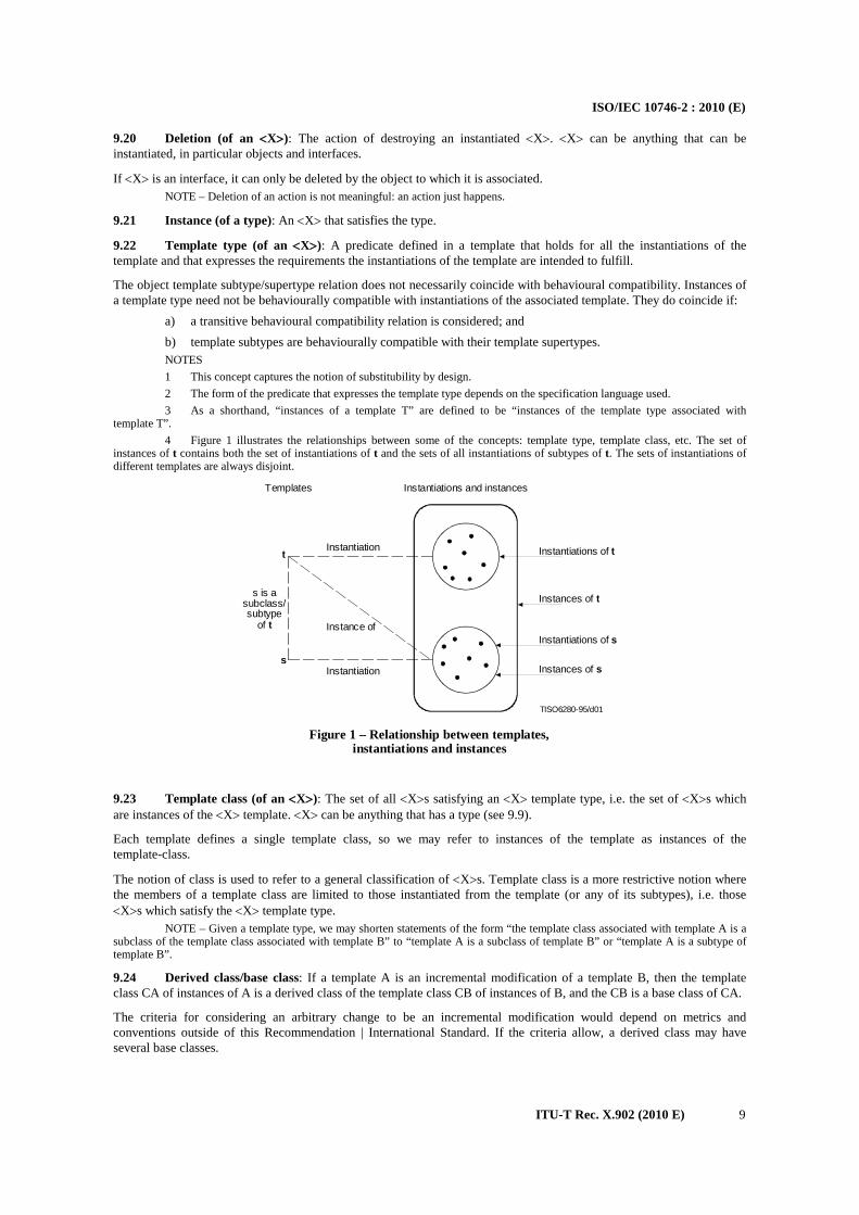
ISO/IEC 10746-2 : 2010 (E)
ITU-T Rec. X.902 (2010 E) 9
9.20 Deletion (of an <X>): The action of destroying an instantiated <X>. <X> can be anything that can be instantiated, in particular objects and interfaces.
If <X> is an interface, it can only be deleted by the object to which it is associated. NOTE – Deletion of an action is not meaningful: an action just happens.
9.21 Instance (of a type): An <X> that satisfies the type.
9.22 Template type (of an <X>): A predicate defined in a template that holds for all the instantiations of the template and that expresses the requirements the instantiations of the template are intended to fulfill.
The object template subtype/supertype relation does not necessarily coincide with behavioural compatibility. Instances of a template type need not be behaviourally compatible with instantiations of the associated template. They do coincide if:
a) a transitive behavioural compatibility relation is considered; and b) template subtypes are behaviourally compatible with their template supertypes. NOTES 1 This concept captures the notion of substitubility by design. 2 The form of the predicate that expresses the template type depends on the specification language used. 3 As a shorthand, “instances of a template T” are defined to be “instances of the template type associated with
template T”. 4 Figure 1 illustrates the relationships between some of the concepts: template type, template class, etc. The set of
instances of t contains both the set of instantiations of t and the sets of all instantiations of subtypes of t. The sets of instantiations of different templates are always disjoint.
TISO6280-95/d01
Instantiations and instancesTemplates
Instantiation
Instance of
Instantiation
Instantiations of t
Instances of t
Instantiations of s
Instances of s
t
s
s is asubclass/subtype
of t
Figure 1 – Relationship between templates,instantiations and instances
FIGURE 1/X.902...[D01] = 7.3 CM
9.23 Template class (of an <X>): The set of all <X>s satisfying an <X> template type, i.e. the set of <X>s which are instances of the <X> template. <X> can be anything that has a type (see 9.9).
Each template defines a single template class, so we may refer to instances of the template as instances of the template-class.
The notion of class is used to refer to a general classification of <X>s. Template class is a more restrictive notion where the members of a template class are limited to those instantiated from the template (or any of its subtypes), i.e. those <X>s which satisfy the <X> template type.
NOTE – Given a template type, we may shorten statements of the form “the template class associated with template A is a subclass of the template class associated with template B” to “template A is a subclass of template B” or “template A is a subtype of template B”.
9.24 Derived class/base class: If a template A is an incremental modification of a template B, then the template class CA of instances of A is a derived class of the template class CB of instances of B, and the CB is a base class of CA.
The criteria for considering an arbitrary change to be an incremental modification would depend on metrics and conventions outside of this Recommendation | International Standard. If the criteria allow, a derived class may have several base classes.

ISO/IEC 10746-2 : 2010 (E)
10 ITU-T Rec. X.902 (2010 E)
The incremental modification relating templates must ensure that self-reference or recursion in the template of the base class becomes self-reference or recursion in the template of the derived class.
The incremental modification may, in general, involve adding to or altering the properties of the base template to obtain the derived template.
Classes can be arranged in an inheritance hierarchy according to derived class/base class relationships. This is the interpretation of inheritance in the ODP Reference Model. If classes can have several base classes, inheritance is said to be multiple. If the criteria prohibit suppression of properties from the base class, inheritance is said to be strict.
It is possible for one class to be a subclass of a second class without being a derived class, and to be a derived class without being a subclass. The inheritance hierarchy (where arcs denote the derived class relation) and the type hierarchy (where arcs denote the subtype or subclass relation) are therefore logically distinct, though they may coincide in whole or in part.
9.25 Factory (for an object): an object that, in response to an interaction initiated by its environment, creates a new object and returns a reference to it to the environment.
9.26 Component: an object that encapsulates its own template, so that the template can be interrogated by interaction with the component. The template and other instantiation parameters are expressed in a form that allows them to be updated during the lifetime of any system of which the component is to form a part, allowing alternative realizations of the component to be substituted.
9.27 Container (for a component): an object that can act as a factory and can provide the necessary environment for subsequent management of the components created by it. The container will, in response to an interaction initiated by its environment, provide information about the components it contains.
9.28 Invariant: A predicate that a specification requires to be true for the entire life time of a set of objects.
9.29 Precondition: A predicate that a specification requires to be true for an action to occur.
9.30 Postcondition: A predicate that a specification requires to be true immediately after the occurrence of an action.
10 Organizational concepts 10.1 <X> Group: A set of objects with a particular characterizing relationship <X>. The relationship <X> characterizes either the structural relationship among objects or an expected common behaviour of the objects.
NOTE – Examples of specialized groups are: a) Addressed group: A set of objects that are addressed in the same way. b) Fault group: A set of objects that have a common fault dependency. For example, it may be assumed that if a
computer fails, all objects executing on that computer also fail. c) Communicating group: A set of objects where all the objects participate in the same sequence of interactions with
their environment. d) Fault tolerant replication group: A communicating group whose purpose is to provide a certain level of tolerance
against some faults.
10.2 Configuration (of objects): A collection of objects able to interact at interfaces. A configuration determines the set of objects involved in each interaction.
The specification of a configuration may be static or may be in terms of the operation of dynamic mechanisms which change the configuration, such as binding and unbinding (see 13.5).
NOTE – A configuration can be expressed in terms of the concepts of concurrent composition. The process of composition generates an equivalent object for the configuration, at a different level of abstraction.
10.3 <X> Domain: A set of objects, each of which is related by a characterizing relationship <X> to a controlling object.
Every domain has a controlling object associated with it.
The controlling object can determine the identities of the collection of objects which comprises the associated domain. The controlling object may communicate with a controlled object dynamically or it may be considered to have communicated in an earlier epoch (see 10.5) of the controlling object. Generally, the controlling object is not a member of the associated domain.
NOTES 1 In enterprise terms, various policies can be administered by the controlling object over the domain.

ISO/IEC 10746-2 : 2010 (E)
ITU-T Rec. X.902 (2010 E) 11
2 Domains can be disjoint or overlapping. 3 By definition, a domain is a group, but not vice versa. 4 Examples of specialized domains are:
10.4 Subdomain: A domain which is a subset of a given domain.
10.5 Epoch: A period of time for which an object displays a particular behaviour. Any one object is in a single epoch at one time, but interacting objects may be in different epochs at the time of interaction.
A change of epoch may be associated with a change in the type of the object, so as to support type evolution. Alternatively, a change of epoch may be associated with a phase in the behaviour of an object of constant type.
For a distributed system to function correctly, the objects composing its configuration must be consistent. Thus, as the whole system evolves through a series of epochs, the individual objects which interact must never be in epochs in which their behaviours are sufficiently different that their concurrent composition leads to a failure. This concept will support the formalization of concepts of version and extensibility.
NOTE – A specification language may need to express: a) the way epochs are labelled; b) the sequence of epochs, and whether all objects need to pass through all members of the sequence; c) the rules for deriving the epoch of a composition from the epochs of its objects, particularly for configurations and
complete systems; d) whether identity of the epoch of an object is necessarily part of the state of that object; e) whether objects can negotiate on the basis of their current epoch identities; f) the relation of epoch to the concepts of local and global time.
10.6 Reference point: An interaction point defined in an architecture for selection as a conformance point in a specification which is compliant with that architecture.
Significant classes of reference point are identified in ODP; details of these, and of the relationship of modelling to conformance, are given in clause 15.
10.7 Conformance point: A reference point at which behaviour may be observed for the purposes of conformance testing.
11 Properties of systems and objects This clause describes the properties which may apply to an ODP system or part of an ODP system.
11.1 Transparencies
11.1.1 Distribution transparency: The property of hiding from the user some specific aspects of the system's complexity needed to support distribution.
NOTES 1 Users may include for instance end-users, application developers and function implementors. 2 Transparencies are often related to structuring into viewpoints. The requirements for transparencies are drawn from
one or more of the designer oriented viewpoints, and are expressed in terms of the properties object interactions are to have in those viewpoints. The templates for the mechanisms that can provide object interactions with the right guaranteed properties are defined in other viewpoints.
Domain Member Class Relationship Controlling Class
Security domain processing object subject to policy set by security authority object
Management domain managed object subject to policy set by management domain object
Addressing domain addressed object address allocated by addressing authority object
Naming domain named object name allocated by name authority object

ISO/IEC 10746-2 : 2010 (E)
12 ITU-T Rec. X.902 (2010 E)
11.2 Policy concepts
11.2.1 Contract: An agreement governing part of the collective behaviour of a set of objects. A contract specifies obligations, permissions and prohibitions for the objects involved.
The specification of a contract may include: a) a specification of the different roles that objects involved in the contract may assume, and the interfaces
associated with the roles; b) Quality of Service constraints (see 11.2.2 and 11.2.3); c) indications of duration or periods of validity; d) indications of behaviour which invalidates the contract; e) liveness and safety conditions. NOTES 1 Objects in a contract need not be hierarchically related, but may be related on a peer-to-peer basis. The requirements
in a contract are not necessarily applicable in the same way to all the objects concerned. 2 A contract can apply at a given reference point in a system. In that case, it specifies the behaviour which can be
expected at the reference point. 3 An object template provides a simple example of a contract. An object template specifies the behaviour common to a
collection of objects. As such, it specifies what the environment of any such objects may assume about their behaviour. Note that, for partial specifications, an object template leaves unspecified the behaviour of an object under certain environmental circumstances (e.g. particular interactions); the contract only extends to the specified behaviour.
11.2.2 Quality of Service: A set of quality requirements on the collective behaviour of one or more objects.
Quality of Service may be specified in a contract or measured and reported after the event.
The Quality of Service may be parameterized. NOTE – Quality of Service is concerned with such characteristics as the rate of information transfer, the latency, the
probability of a communication being disrupted, the probability of system failure, the probability of storage failure, etc.
11.2.3 Environment contract: A contract between an object and its environment, including Quality of Service constraints, usage and management constraints.
Quality of Service constraints include: – temporal constraints (e.g. deadlines); – volume constraints (e.g. throughput); – dependability constraints covering aspects of availability, reliability, maintainability, security and safety
(e.g. mean time between failures).
Usage and management constraints include: – location constraints (i.e. selected locations in space and time); – distribution transparency constraints (i.e. selected distribution transparencies).
Quality of Service constraints can imply usage and management constraints. For instance, some Quality of Service constraints (e.g. availability) are satisfied by provision of one or more distribution transparencies (e.g. replication).
Environment constraints can describe both: – requirements placed on an object’s environment for the correct behaviour of the object; – constraints on the object behaviour in a correct environment.
11.2.4 Obligation: A prescription that a particular behaviour is required. An obligation is fulfilled by the occurrence of the prescribed behaviour.
11.2.5 Permission: A prescription that a particular behaviour is allowed to occur. A permission is equivalent to there being no obligation for the behaviour not to occur.
11.2.6 Prohibition: A prescription that a particular behaviour must not occur. A prohibition is equivalent to there being an obligation for the behaviour not to occur.
11.2.7 Rule: A constraint on a system specification. Where appropriate, a rule can be expressed as an obligation, a permission or a prohibition.
NOTE – Rules may apply to the structure, behaviour or other properties of the system, including for example Quality of Service

ISO/IEC 10746-2 : 2010 (E)
ITU-T Rec. X.902 (2010 E) 13
11.2.8 Policy: A constraint on a system specification foreseen at design time, but whose detail is determined subsequent to the original design, and capable of being modified from time to time in order to manage the system in changing circumstances.
NOTES 1 Policies can be applied in any viewpoint; examples are an enterprise delegation policy, a computational persistence
policy or an engineering scheduling or quality support policy. 2 The expectation of change is fundamental to the concept of policy, and a rule that does not envisage change is not a
policy. 3 Policies may be expressed in terms of obligations, permissions or prohibitions, but this is not necessary for simple
policies.
11.2.9 Policy Declaration: An element in a specification defined in order to allow incorporation of future constraints, together with rules determining the allowed form of acceptable constraints and the circumstances in which such constraints can be applied.
11.2.10 Policy Value: The specific constraints associated with a policy in some particular epoch.
11.2.11 Policy Envelope: The set of acceptable policy values that could be applied at a particular policy declaration. Restricting policy values to be within the policy envelope allows future flexibility but guarantees that the required properties of the system design will be preserved by all valid policies.
11.2.12 Policy Setting Behaviour: the behaviour defined in a specification via which a policy may be changed. A policy setting behaviour can be both an establishing behaviour (13.2.1) and a terminating behaviour (13.2.5).
11.3 Temporal properties
11.3.1 Persistence: The property that an object continues to exist across changes of contractual context (see 13.2.3) or of epoch.
11.3.2 Isochronicity: A sequence of actions is isochronous if every adjacent pair of actions in the sequence occupy unique, equally-sized, adjacent intervals in time.
12 Naming concepts NOTE – Naming concepts and the mechanisms that support them in the context of distributed systems are further specified
in ITU-T Rec X.910 | ISO/IEC 14771:1999, Information Technology – Open Distributed Processing – Naming framework
12.1 Name: A term which, in a given naming context, refers to an entity.
12.2 Identifier: An unambiguous name, in a given naming context.
12.3 Name space: A set of terms usable as names.
12.4 Naming context: A relation between a set of names and a set of entities. The set of names belongs to a single name space.
12.5 Naming action: An action that associates a term from a name space with a given entity.
All naming actions are relative to a naming context.
12.6 Naming domain: A subset of a naming context such that all naming actions are performed by the controlling object of the domain (the name authority object).
NOTE – “Naming domain” is an instance of the <X> domain concept (see 10.3).
12.7 Naming graph: A directed graph where each vertex denotes a naming context, and where each edge denotes an association between:
– a name appearing in the source naming context; and – the target naming context. NOTE – The existence of an edge between two naming contexts in a naming graph means that the target naming context
can be reached (identified) from the source naming context.
12.8 Name resolution: The process by which, given an initial name and an initial naming context, an association between a name and the entity designated by the initial name can be found.
NOTE – The name resolution process does not necessarily provide sufficient information to interact with the designated entity.

ISO/IEC 10746-2 : 2010 (E)
14 ITU-T Rec. X.902 (2010 E)
13 Concepts for behaviour
13.1 Activity structure
13.1.1 Chain (of actions): A sequence of actions within an activity where, for each adjacent pair of actions, occurrence of the first action is necessary for the occurrence of the second action.
13.1.2 Thread: A chain of actions, where at least one object participates in all the actions of the chain.
An object may have associated with it one single thread or many threads simultaneously.
13.1.3 Joining action: An action shared between two or more chains resulting in a single chain.
13.1.4 Dividing action: An action which enables two or more chains.
There are two cases of a dividing action, depending on whether the enabled chains are required to join eventually.
13.1.5 Forking action: A dividing action, where the enabled chains must (subject to failure) eventually join each other, i.e. the enabled chains cannot join other chains and they cannot terminate separately.
13.1.6 Spawn action: A dividing action, where the enabled chains will not join. The enabled chains may interact and they may terminate separately.
13.1.7 Head action: In a given activity, an action that has no predecessor.
13.1.8 Subactivity: A subgraph of an activity which is itself an activity and which satisfies the following condition. For any pair of fork-join actions in the parent acitivity, if one of these actions is included in the subgraph, then both must be included in the subgraph.
13.2 Contractual behaviour
The concepts introduced here are illustrated in Figure 2.
TISO6290-95/d02
Establishingbehaviour
Terminatingbehaviour
Time
Enabled behaviour
Period of liaison
Period during whichcontext exists
Figure 2 – Liaison and related concepts FIGURE 2/X.902...[D02] = 3.7 CM
13.2.1 Establishing behaviour: The behaviour by which a given contract is put in place between given objects. An establishing behaviour can be:
a) explicit, resulting from the interactions of objects that will take part in the contract; or b) implicit, being performed by an external agency (e.g. a third party object, not taking part in the contract) or
having been performed in a previous epoch. NOTES 1 Negotiation is an example of a particular kind of establishing behaviour in which information is exchanged in the
process of reaching a common view of permitted future behaviour. 2 Publication is an example of a particular kind of establishing behaviour in which information is distributed from one
object to a number of others. 3 Explicit establishing behaviour must include an instantiation of the template associated with the contract. This may
follow a possible negotiation/publication about which contract to set up and which template to instantiate, and with what parameters.
13.2.2 Enabled behaviour: The behaviour characterizing a set of objects which becomes possible as a result of establishing behaviour.
The enabled behaviour will not necessarily be the same for all objects involved in the contractual context.
13.2.3 Contractual context: The knowledge that a particular contract is in place, and thus that a particular behaviour of a set of objects is required.

ISO/IEC 10746-2 : 2010 (E)
ITU-T Rec. X.902 (2010 E) 15
An object may be in a number of contractual contexts simultaneously; the behaviour is constrained to the intersection of the behaviours prescribed by each contractual context.
NOTE – In OSI, the concept of a presentation context is an example of a contractual context which can be established at connection establishment time or subsequently.
13.2.4 Liaison: The relationship between a set of objects which results from the performance of some establishing behaviour; the state of having a contractual context in common.
A liaison is characterized by the corresponding enabled behaviour. NOTES 1 Examples of liaisons which result from different establishing behaviours are: a) a dialogue (as in OSI-TP); b) a binding (see 13.5.2); c) a distributed transaction (as in OSI-TP); d) an (N)-connection (as in OSI); e) an association between (N)-entities enabling them to participate in (N)-connectionless communication (as
in OSI); f) a relationship between files and processes which access the files. 2 Certain behaviours may be contingent on the establishment of multiple related liaisons. For example, a distributed
transaction may depend on both the liaison between the transaction users and the supporting association. The liaison between the transaction users (the distributed transaction) may continue to exist, but be inactive, when the association is broken.
3 A liaison may involve more than two objects. The objects involved in a liaison do not necessarily all have equivalent roles. Thus, there may be liaisons for the collection or distribution of information. The number of participants and the roles of the participants are determined by the contract expressed by the liaison.
4 Agreeing a contract implies establishment of a contractual context and acceptance of any contractual obligation; the act of agreement to the contract makes the enabled behaviour possible for as long as the context or liaison exists. In practice, contexts may be arbitrarily nested and the enabled behaviour at an outer level may negotiate and agree a contract enabling further behaviour at an inner level of the hierarchy.
13.2.5 Terminating behaviour: The behaviour which breaks down a liaison and repudiates the corresponding contractual context and the corresponding contract.
A terminating behaviour must be explicitly identified as such in the contract if the establishing behaviour was explicit.
13.3 Service concepts
13.3.1 Service: a behaviour, triggered by an interaction, that adds value for the service users by creating, modifying, or consuming information; the changes become visible in the service provider’s environment.
NOTES 1 Services are associated with interfaces and defined by the structural, behavioural and semantic rules of the interaction
types involved. 2 A service can be characterized by a service type. A service is identifiable. A service may be composed of other
services. 3 A service is in general invoked from within a liaison. Rules can be associated with the liaison, which refine the
service for the duration of the liaison. 4 The service may be a complex behaviour, including both interactions and internal actions. 5 The provision of a service involves a collaboration between its provider and user. This collaboration may involve a
complex series of interactions..
13.4 Causality
Identification of causality allows the categorization of roles of interacting objects. This clause gives a basic set of roles.
Causality implies a constraint on the behaviour of each of the participating objects while they are interacting. Causality will be identified in the definition of classes (or subclasses) to which interacting objects belong, or in the refinement of templates for their classes (or subclasses).
13.4.1 Initiating object (with respect to a communication): An object causing a communication. NOTE – The identification of an initiating object with respect to a communication involves an interpretation of the intent of
the communication.
13.4.2 Responding object: An object taking part in a communication, which is not the initiating object.
13.4.3 Producer object (with respect to communication): An object which is the source of the information conveyed.

ISO/IEC 10746-2 : 2010 (E)
16 ITU-T Rec. X.902 (2010 E)
The usage of this term does not imply any specific communication mechanism.
13.4.4 Consumer object (with respect to communication): An object which is a sink of the information conveyed.
The usage of this term does not imply any specific communication mechanism.
13.4.5 Client object: An object which requests that a service be performed by another object.
13.4.6 Server object: An object which performs some service on behalf of a client object.
Client/server relationships of a different nature (or level of abstraction) may exist between an object and different compositions of the objects with which it communicates.
NOTE – With respect to a specific interaction, client and server objects perform client and server roles respectively. However, a given object may be involved in a number of interactions and may perform client or server roles in each of these interactions; the interactions will, in general, be of different types and are not necessarily expressed at the same level of abstraction.
13.5 Establishing behaviours
13.5.1 Binding behaviour: An establishing behaviour between two or more interfaces (and hence between their supporting objects).
NOTE – “To bind” means “to execute a binding behaviour”.
13.5.2 Binding: A contractual context, resulting from a given establishing behaviour.
Establishing behaviour, contractual context and enabled behaviour may involve just two object interfaces or more than two.
An object which initiates an establishing behaviour may or may not take part in the subsequent enabled behaviour.
Enabled behaviour (and, by analogy, contractual context) may be uniform (i.e. each participating object can do the same as every other) or non-uniform (i.e. one participating object has a different role from another, as in client and server).
There is no necessary correspondence between an object which initiates establishing behaviour and a particular role in non-uniform enabled behaviours (e.g. in a client-server contractual context, either object could validly have initiated the establishing behaviour).
13.5.3 Binding precondition: A set of conditions required for the successful execution of a binding behaviour.
The objects performing the binding behaviour must possess identifiers for all the interfaces involved in the binding. There may be additional preconditions.
13.5.4 Unbinding behaviour: A behaviour that terminates a binding, i.e. a terminating behaviour for the binding.
13.5.5 Trading: The interaction between objects in which information about new or potential contracts is exchanged via a third party object. It involves:
a) Exporting: The provision of an identifier to an interface which is claimed to meet some statement of requirements (i.e. offer a potential contract).
b) Importing: The provision of an identifier to an interface which matches a given statement of requirements, allowing a future binding behaviour to take place (i.e. the establishment of a contract).
13.6 Dependability
13.6.1 Failure: Violation of a contract. NOTES 1 The behaviour specified in the contract is, by definition, the “correct behaviour”. A failure is thus a deviation from
compliance with the correct behaviour. 2 The ways an object can fail are called its failure modes. Several types of failure modes can be distinguished: – arbitrary failures (non-compliance with the specification – the most general failure mode); – omission failure (when expected interactions not take place); – crash failures (persistent omission failures); – timing failures (incorrectness due to untimely behaviour). 3 A failure can be perceived differently by different objects in the environment of the object that exhibits it. A failure
may be: consistent if all the perceptions of the failure are the same; inconsistent if objects in the environment may have different perceptions of a given failure.
13.6.2 Error: Part of an object state which is liable to lead to failures. A manifestation of a fault (see 13.6.3) in an object.

ISO/IEC 10746-2 : 2010 (E)
ITU-T Rec. X.902 (2010 E) 17
NOTES 1 Whether an error will actually lead to a failure depends on the object decomposition, its internal redundancy, and on
the object behaviour. Corrective action may prevent an error from causing a failure. 2 An error may be latent (i.e. not recognized as such) or detected. An error may disappear before being detected.
13.6.3 Fault: A situation that may cause errors to occur in an object. NOTES 1 Faults causing an error may appear from the time an object is specified through to the time it is destroyed. Faults in an
early epoch (e.g. design faults) may not lead to failure until a later epoch (e.g. execution time). 2 A fault is either active or dormant. A fault is active when it produces errors. The presence of active faults is
determined only by the detection of errors. 3 Faults can be: – accidental (that appear or are created fortuitously) or intentional (created deliberately); – physical (due to some physical phenomena) or human-made (resulting from human behaviour); – internal (part of an object state that may cause an error) or external (resulting from interference or interaction
with the environment); – permanent or temporary. 4 The definitions of fault, error and failure imply, recursively, causal dependencies between faults, errors and failures: – a fault can lead to an error (it will lead to an error if it becomes active); – an error can lead to a system’s failure (it will lead to a failure unless the system can deal with it); – a failure occurs when an error affects the correctness of the service delivered by a system (or system
component).
13.6.4 Stability: The property that an object has with respect to a given failure mode if it cannot exhibit that failure mode.
14 Management concepts Management in ODP is concerned with overall systems management, including application management and communication management.
14.1 Application management: The management of applications within an ODP system. Some aspects of applications management are common to all applications and are termed application independent management. Those aspects which are specific to a given application are termed application specific management.
14.2 Communication management: Management of objects which support the communication betwen objects within an ODP system.
14.3 Management information: Knowledge concerning objects which are of relevance to management.
14.4 Managed role: The view of the management interface of an object which is being managed within an ODP system.
NOTE – Where the object provides OSI communication services, OSI Management refers to the management interface as a managed object.
14.5 Managing role: The view of an object which is performing managing actions.
14.6 Management notification: An event notification initiated by an object operating in a managed role.
15 ODP approach to conformance NOTE – The definitions of concepts in clauses 6-14 do not apply in this clause, and terms such as “interface”, “system”,
and “role” are used in their normal English sense.
15.1 Conformance to ODP standards
Conformance relates an implementation to a standard. Any proposition that is true of the specification must be true in its implementation.
A conformance statement is a statement that identifies conformance points of a specification and states the behaviour which must be satisfied at these points. Conformance statements will only occur in standards which are intended to constrain some feature of a real implementation, so that there exists, in principle, the possibility of testing.

ISO/IEC 10746-2 : 2010 (E)
18 ITU-T Rec. X.902 (2010 E)
The RM-ODP identifies certain reference points in the architecture as potentially declarable as conformance points in specifications. That is, as points at which conformance may be tested and which will, therefore, need to be accessible for test. However, the requirement that a particular reference point be considered a conformance point must be stated explicitly in the conformance statement of the specification concerned.
Requirements for the necessary consistency of one member of the family of ODP standards with another (such as the RM-ODP) are established during the standardization process. Adherence to these requirements is called compliance.
If a specification is compliant, directly or indirectly, with some other standards, then the propositions which are true of those standards are also true of a conformant implementation of the specification.
15.2 Testing and reference points
The truth of a statement in an implementation can only be determined by testing and is based on a mapping from terms in the specification to observable aspects of the implementation.
At any specific level of abstraction, a test is a series of observable stimuli and events, performed at prescribed points known as reference points, and only at these points. These reference points are accessible interfaces. A system component for which conformance is claimed is seen as a black box, testable only at its external linkages. Thus, for example, conformance to OSI protocol specifications is not dependent on any internal structure of the system under test.
15.3 Classes of reference points
A conformance point is a reference point where a test can be made to see if a system meets a set of conformance criteria. A conformance statement must identify where the conformance points are, and what criteria are satisfied at these points. Four classes of reference points at which conformance tests can be applied are defined.
15.3.1 Programmatic reference point: A reference point at which a programmatic interface can be established to allow access to a function. A programmatic conformance requirement is stated in terms of a behavioural compatibility with the intent that one object be replaced by another. A programmatic interface is an interface which is realized through a programming language binding.
NOTE – For example, a programmatic reference point may be established in a database standard to support a language binding at some level of abstraction.
15.3.2 Perceptual reference point: A reference point at which there is some interaction between the system and the physical world.
NOTES 1 A perceptual reference point may be e.g. a human-computer interface or a robotic interface (specified in terms of the
interactions of the robot with its physical environment). 2 A human-computer interface perceptual conformance requirement is stated in terms of the form of information
presented to a human being and the interaction metaphor and dialogues the human may be engaged in. The specification of a human-computer interface in an ODP system specification is discussed in ITU-T Rec. X.903 | ISO/IEC 10746-3, Annex B.
3 A perceptual reference point may, for example, be established in a graphics standard.
15.3.3 Interworking reference point: A reference point at which an interface can be established to allow communication between two or more systems. An interworking conformance requirement is stated in terms of the exchange of information between two or more systems. Interworking conformance involves interconnection of reference points.
NOTE – For example, OSI standards are based on the interconnection of interworking reference points (the physical medium).
15.3.4 Interchange reference point: A reference point at which an external physical storage medium can be introduced into the system. An interchange conformance requirement is stated in terms of the behaviour (access methods and formats) of some physical medium so that information can be recorded on one system and then physically transferred, directly or indirectly, to be used on another system.
NOTE – For example, some information interchange standards are based on interchange reference points.
15.4 Change of configuration
The testing of conformance may take place at a single reference point, or it may involve some degree of consistency over use in a series of configurations involving several reference points. This may involve the testing of conformance to:
a) the requirement for a component to be able to operate after some preparatory process to adapt it to the local environment;

ISO/IEC 10746-2 : 2010 (E)
ITU-T Rec. X.902 (2010 E) 19
b) the requirement for a component to operate according to its specification at a particular reference point from initialization onwards;
c) the requirement for a component to continue to work when moved into a similar environment during operation.
The properties being tested above give rise to attributes of the objects or interfaces involved, as follows.
15.4.1 Portability: The property that the reference points of an object allow it to be adapted to a variety of configurations.
NOTE – If the reference point is a programmatic reference point, the result can be source-code or execution portability. If it is an interworking reference point, the result is equipment portability.
15.4.2 Migratability: The ability to change the configuration, substituting one reference point of an object for another while the object is being used.
15.5 The conformance testing process
Conformance is a concept which can be applied at any level of abstraction. For example, a very detailed perceptual conformance is expected to a standard defining character fonts, but a much more abstract perceptual conformance applies to screen layout rules.
The more abstract a specification is, the more difficult it is to test. An increasing amount of implementation-specific interpretation is needed to establish that the more abstract propositions about the implementation are in fact true. It is not clear that direct testing of very abstract specifications is possible at reasonable cost using currently available or foreseeable techniques.
Conformance testing can take many forms, mirroring different forms of specification, implementation and deployment processes. The description below concentrates on third-party testing, because this gives the clearest separation of roles, but the same distinctions and responsibilities can be identified in more integrated processes, such as those associated with modern, modularised, late-bound, loosely-coupled systems involving runtime conformance assurance performed by the distribution infrastructure, or otherwise
The testing process makes reference to a specification. To be complete, the specification must contain: a) the behaviour of the object being standardized and the way this behaviour must be achieved; b) a list of the primitive terms used in the specification when making the statements of behaviour; c) a conformance statement indicating the conformance points, what implementations must do at them and
what information implementors must supply (corresponding to the OSI notions of PICS and PIXIT).
In principle, there are two roles in providing a specification for testing: the system specifier and the system owner. The system specifier is responsible for the content of the specification and determines the possible behaviour of an implementation of that specification.
The system owner is responsible for the specific use to which the implementation will be put. The system owner may only be interested in a subset of the possible behaviour and, thus, may specify constraints on the scope of an implementation and, hence, on the nature of the conformance testing required.
There are two roles in the testing process: the implementor and the tester. The implementor constructs an implementation on the basis of the specification within the scope defined by the system owner. The implementor must provide a statement of a mapping from all the terms used in the specification to things or happenings in the real world. Thus, the interfaces corresponding to the conformance points must be indicated and the representation of signals given. If the specification is abstract, the mapping of its basic terms to the real world may itself be complex. For example, in a computational viewpoint specification (see ITU-T Rec. X.903 | ISO/IEC 10746-3), the primitive terms might be a set of interactions between objects. The implementor wishing to conform to the computational viewpoint specification would have to indicate how the interactions were provided, either by reference to an engineering specification or by providing a detailed description of an unstandardized mechanism (although this course limits the field of application of the implementation to systems in which there is an agreement to use the unstandardized mechanism).
The tester observes the system under test. Testing involves some shared behaviour between the testing process and the system under test. If this behaviour is given a causal labelling, there is a spectrum of testing types from:
a) passive testing, in which all behaviour is originated by the system under test and recorded by the tester; b) active testing, in which behaviour is originated and recorded by the tester.
Normally, the specification of the system under test is in the form of an interface, as is the specification of the tester and test procedures. When testing takes place, these interfaces are bound.

ISO/IEC 10746-2 : 2010 (E)
20 ITU-T Rec. X.902 (2010 E)
The tester must interpret its observations using the mapping provided by the implementor to yield propositions about the implementation which can then be checked to show that they are also true in the specification, within the scope defined by the system owner.
15.6 The result of testing
The testing process succeeds if all the checks against the specification succeed. However, it can fail because: a) the specification is logically inconsistent or incomplete, so that the propositions about the implementation
cannot be checked (this should not occur); b) the mapping given by the implementor is logically incomplete, so that it is inconsistent or observations
cannot be related to terms in the specification; testing is impossible; c) the observed behaviour cannot be interpreted according to the mapping given by the implementor. The
behaviour of the system is not meaningful in terms of the specification, and so the test fails; d) the behaviour is interpreted to give terms expressed in the specification, but these occur in such a way that
they yield propositions which are not true in the specification, and so the test fails.
15.7 Relation between reference points
The flow of information between modelled system components may pass through more than one reference point. For example, a distributed system may involve interactions of two components A and B, but communication between them may pass in turn through a programmatic interface, a point of interconnection and a further programmatic interface.
A refinement of the same system may show interconnected components that have more than one component on the communication path between them.
In either case, conformance testing may involve: a) testing the information flow at each of these reference points; b) testing the consistency between events at pairs of reference points.
In general, testing for correct behaviour of a configuration of objects will require testing that statements about communication interfaces are true, but it will also require observation of other interfaces of these objects, so that the statements about the composition can also be checked.
The general notion of conformance takes into account the relation between several conformance points. Since the specification related to a given conformance point may be expressed at various levels of abstraction, testing at a given conformance point will always involve interpretation at the appropriate level of abstraction. Thus, the testing of the global behaviour requires coordinated testing at all the conformance points involved and the use of the appropriate interpretation at each point.
In particular, conformance of a template to a given programmatic interface can only be asserted when considering the language binding for the language in which the template has been written, and compliance of the written template to the language binding specification, which must itself be conformant with the abstract interface specification.

ISO/IEC 10746-2 : 2010 (E)
ITU-T Rec. X.902 (2010 E) 21
Index NOTE – Associated with each index entry is the clause or subclause where the index entry is defined.
<X> Domain, 10.3 <X> Group, 10.1 <X> Pattern 9.8 <X> Template, 9.13 Abstraction, 6.3 Action, 8.3 Action signature 9.14 Activity, 8.6 Application management, 14.1 Architecture (of a system), 6.6 Atomicity, 6.4 Base class, 9.24 Behaviour (of an object), 8.7 Behavioural compatibility, 9.4 Binding behaviour, 13.5.1 Binding precondition, 13.5.3 Binding, 13.5.2 Chain (of actions), 13.1.1 Class (of <X>s), 9.10 Client object, 13.4.5 Coerced behavioural compatibility, 9.4 Communication management, 14.2 Communication, 8.9 Compliance, 15.1 Component 9.26 Composite object, 9.2 Composition, 9.1 Configuration (of objects), 10.2 Conformance point, 10.7 Consumer object, 13.4.4 Container (for a component), 9.27 Contract, 11.2.1 Contractual context, 13.2.3 Creation (of an <X>), 9.18 Data, 3.2.6 Decomposition, 9.3 Deletion (of an <X>), 9.20 Derived class, 9.24 Distributed processing, 3.2.1 Distribution transparency, 11.1.1 Dividing action, 13.1.4 Enabled behaviour, 13.2.2 Entity, 6.1 Environment (of an object), 8.2 Environment contract, 11.2.3 Epoch, 10.5 Error, 13.6.2 Establishing behaviour, 13.2.1
Event, 8.4 Event notification, 8.4 Factory (for an object), 9.25 Failure, 13.6.1 Fault, 13.6.3 Forking action, 13.1.5 Head action, 13.1.7 Identifier, 12.2 Information, 3.2.5 Initiating object (with respect to a communication), 13.4.1 Instance (of a type), 9.21 Instantiation (of an <X> template), 9.16 Interaction point, 8.12 Interaction, 8.3 Interchange reference point, 15.3.4 Interface signature, 9.15 Interface, 8.5 Internal action, 8.3 Interoperability 9.5 Interworking reference point, 15.3.3 Introduction (of an <X>), 9.19 Invariant, 9.28 Isochronicity, 11.3.2 Joining action, 13.1.3 Liaison, 13.2.4 Location in space, 8.10 Location in time, 8.11 Managed role, 14.4 Management information, 14.3 Management notification 14.6 Managing role, 14.5 Migratability, 15.4.2 Model, 7.3 Name resolution, 12.8 Name space, 12.3 Name, 12.1 Naming action, 12.5 Naming context, 12.4 Naming domain, 12.6 Naming graph, 12.7 Natural behavioural compatibility, 9.4 Notation 7.5 Object, 8.1 Obligation, 11.2.4 ODP standards, 3.2.2 ODP System, 3.2.4 Open Distributed Processing, 3.2.3

ISO/IEC 10746-2 : 2010 (E)
22 ITU-T Rec. X.902 (1995 E)
Perceptual reference point, 15.3.2 Permission, 11.2.5 Persistence, 11.3.1 Policy envelope 11.2.11 Policy declaration 11.2.9 Policy setting behaviour 11.2.12 Policy value 11.2.10 Policy, 11.2.8 Portability, 15.4.1 Postcondition, 9.30 Precondition, 9.29 Producer object (with respect to a communication), 13.4.3 Programmatic reference point, 15.3.1 Prohibition, 11.2.6 Proposition, 6.2 Quality of Service, 11.2.2 Reference point, 10.6 Refinement, 9.6 Relation 8.13 Relationhip 8.14 Responding object, 13.4.2 Role, 9.17 Rule 11.2.7 Sentence, 7.2 Server object, 13.4.6 Service 13.3.1 Spawn action, 13.1.6 Specification 7.4 Stability, 13.6.4 State (of an object), 8.8 Subactivity, 13.1.8 Subclass, 9.12 Subdomain, 10.4 Subtype, 9.11 Superclass, 9.12 Supertype, 9.11 System, 6.5 Template class (of an <X>), 9.23 Template type (of an <X>), 9.22 Term, 7.1 Terminating behaviour, 13.2.5 Thread, 13.1.2 Trace, 9.7 Trading, 13.5.5 Type (of an <X>), 9.9 Unbinding behavior, 13.5.4 Viewpoint (on a system), 3.2.7 Viewpoint correspondence 3.2.8


Bibliography
[AMB+04] Alain Abran, James W. Moore, Pierre Bourque, Robert Dupuis, andLeonard L. Tripp. Guide to the Software Engineering Body of Knowl-edge: 2004 Edition - SWEBOK. IEEE, 2004.
[Ari91] Aristotle. Metaphysics. Oxford University Press, (1991).
[Bac10] Francis Bacon. Novum Organum. Forgotten Books, 2010.
[Bar88] Marie-France Barthet. Logiciels interactifs et ergonomie. DunodInformatique, Paris, 1988.
[Buc68] Walter Frederick Buckley. Modern Systems Research for the Behav-ioral Scientist. Aldine Publishing Company, 1968.
[Bux07] Bill Buxton. Sketching User Experiences: Getting the Design Rightand the Right Design. Morgan Kaufmann, 2007.
[Cha09] Robert Charette. Why software fails. http://bit.ly/7wVjq, June 2009.
[Che99] Peter Checkland. Systems Thinking, Systems Practice: Includes a30-Year Retrospective. Wiley, 1999.
[CHI10] ACM CHI. Model-driven development of advanced user interfaces,August 2010.
[CNM83] Stuart K. Card, Allen Newell, and Thomas P. Moran. The Psychologyof Human-Computer Interaction. L. Erlbaum Associates Inc., 1983.
[CRC07] Alan Cooper, Robert Reimann, and David Cronin. About Face. Wiley,3rd edition, 2007.
[Dar93] Charles Darwin. The Autobiography of Charles Darwin: 1809 - 1882.Nora Barlow, 1993.
[Des37] Rene Descartes. Discours de la methode pour bien conduire sa raison,et chercher la verite dans les sciences. Rene Descartes, 1637.
189

BIBLIOGRAPHY CHAPTER A
[Dij82] Edsger W. Dijkstra. Selected Writings in Computing: A PersonalPerspective. Springer-Verlag, 1982.
[Fly06] Bent Flyvbjerg. Five misunderstandings about case-study research.Qualitative Inquiry, 12(2):219 – 245, 2006.
[Gai81] Brian R. Gaines. The technology of interaction: Dialogue program-ming rules. International Journal of Man-Machine Studies, 1981.
[Gal07] Wilbert O. Galitz. The Essential Guide to User Interface Design:An Introduction to GUI Design Principles and Techniques. WileyPublishing Inc., third edition edition, 2007.
[Inc06] Apple Inc. Apple Human Interface Guidelines, Oct 2006.
[Ins73] American National Standards Insitute. American National Psychoa-coustical Terminology. American Standards Association, 1973.
[Jac01] Michael Jackson. Problem frames: Analyzing and Structuring Soft-ware Development Problems. Addison Wesley, 2001.
[JK96] B. E. John and D. E. Kieras. The goms family of user interfacesanalysis technique: Comparison and contrasts. In ACM Transactionson Computer-Human Interaction, number 3, pages 320–351, 1996.
[Jr.85] Albert F. Case Jr. Computer-aided software engineerng (case):Technology for improving software development productivity. DATABASE, 17(1):35–43, 1985.
[Knu74] Donald E. Knuth. Computer programming as an art. Communicationsof the ACM 1974/Vol. 17, No. 12, pages 667–673, 1974.
[Kuh05] Thomas Kuhne. What is a model? Dagstuhl Seminar 04101,Dagstuhl, 2005.
[Lan86] Keith Lantz. On user interface reference models. Technical report,Nov 1986.
[Lim04] Quentin Limbourg. Multi-Path Development of User Interfaces. PhDthesis, Universite Catholique de Louvain, Oct 2004.
[LM86] Gene Lynch and Jon Meads. In search of a user interface referencemodel: Report on the sigchi workshop on user interface referencemodels. SIGCHI Bull., 18(2):25–33, Nov 1986.
190

BIBLIOGRAPHY CHAPTER A
[LV04] Quentin Limbourg and Jean Vanderdonckt. Usixml: A user inter-face descriptoin language supporting multiple levels of independence.In Engineering Advanced Web Applications, pages 325–338. RintonPress, 2004.
[Mah03] Bernd Mahr. Modellieren. Beobachtungen und Gedanken zurGeschichte des Modellbegriffs. Horst Bredekamp, 2003.
[Mah08] Bernd Mahr. Ein Modell des Modellseins - Ein Beitrag zur Aufklarungdes Modellbegriffs. Peter Lang Verlag, 2008.
[Mah09] Bernd Mahr. Information science and the logic of models. InformatikSpektrum, 32(3), 2009.
[Man05] Bernard Mandeville. The Fable of the Bees: And Other Writings.Hacket Publishing Company, 1997 (1705).
[Mar98] P. Marinis. Hellenic World-Vision. Nea Thesis Editions, 1998.
[MB79] Stephen McAdams and Albert Bregman. Hearing musical streams.Computer Music Journal, 3(4), 1979.
[ME68] Karl Marx and Friedrich Engels. Karl Marx - Friedrich Engels - Werke,Band 23, Das Kapital, Bd. I. Dietz Verlag, 1968.
[Met09] Wolfgang Metzer. Laws of Seeing. MIT Press, 2009.
[MK09] Rahul Mohan and Vinay Kulkarni. Model driven development ofgraphical user interfaces for enterprise business applications – experi-ence, lessons learnt and a way forward. In Model Driven EngineeringLanguages and Systems. Springer, Berlin / Heidelberg, 2009.
[MM92] J. L. Miller and J. G. Miller. Greater than the sum of its parts. i.subsystems which process both matter-energy and information. InSystems Research and Behavioral Science, volume 37, pages 1–9.Wiley, 1992.
[MMJS09] M. Minovic, M. Milovanovic, M. Jovanovic, and D. Starcevic. Modeldriven development of user interfaces for educational games. In Hu-man System Interactions, 2009.
[Mos93] Hanspeter Mossenbock. Objektorientierte Programmierung.Springer-Verlag, 1993.
191

BIBLIOGRAPHY CHAPTER A
[Nor90] Donald Norman. The Design of Everyday Things. Doubleday Busi-ness, 1990.
[Ols67] Harry F. Olson. Music, Physics and Engineering. Dover Publications,1967.
[Pal94] Philippe Palanque. Petri net based design of user-driven interfacesusing the interactive cooperative objects formalism. In Proceedingsof the 1st Eurographics Workshop on Design, Specification, and Ver-ification of Interactive Systems. DSV-IS, Springer-Verlag, 1994.
[Pan83] Erwin Panofsky. Meaning in the Visual Arts. University of ChicagoPress, 1983.
[PE99] Angel Puerta and Jacob Eisenstein. Towards a general computationalframework for model-based interface development systems. pages171–178, Jan 1999.
[PEGM94] Angel Puerta, Henrik Eriksson, John Gennari, and Mark Musen. Be-yond data models for automated user interface generation. pages353–366, 1994.
[Phi09] Philips. Philips’ brand promise. http://bit.ly/cXu6kd, June 2009.
[PlaBC] Plato. Philebus. Philebus, 360 B.C.
[Pla07] Plato. The Republic. Penguin Classics, 2007.
[PS97] Angela Puerta and Pedro Szekely. A model-based interface develop-ment environment. IEEE Softw., 14(4):40–47, Aug 1997.
[Ras94] Jef Raskin. On user interface intuitivity. Communications of theACM 1994/Vol. 37, No. 9, Nov 1994.
[Ras07] Jef Raskin. The Humane Interface. Addison Wesley, 2007.
[Ree10] Trygve Reenskaug. Mvc xerox parc 1978-79. http://bit.ly/17ViZJ,May 2010.
[RG01] Robbins-Gioia. Robbins-gioia survey (2001). Robbins-Gioia Survey(2001), 2001.
[RO97] RM-ODP. RMODP Foundations, Oct 1997.
[RO98] RM-ODP. ISO/IEC 10746-1:1998(E) - (RM-ODP Overview), Nov1998.
192

BIBLIOGRAPHY CHAPTER A
[RS08] Bernhard Rieder and Mirko Tobias Schafer. Beyond engineering.Beyond Engineering, 2008.
[Sen94] Peter Senge. The Fifth Discipline: The Art & Practice of the LearningOrganization. Doubleday Business, 1994.
[Sim80] Helen Simons. Towards a science of the singular: Essays about casestudy in educational research and evaluation. Technical report, Uni-versity of East Anglia, Norwich: Centre for Applied Research in Ed-ucation, 1980.
[Smi76] Adam Smith. An Inquiry into the Nature and Causes of the Wealthof Nations. W. Strahan and T. Cadell, London, 1776.
[Soy97] Susan K. Soy. The case study as a research method. University ofTexas at Austin, 1997.
[SP00] Paulo Pinheiro Da Silva and Norman W. Paton. Umli: The unifiedmodeling language for interactive applications. In Proceedings ofUML2000, volume 1939 of LNCS, pages 117–132. Springer, 2000.
[SP03] Paulo Silva and Norman Paton. User interface modeling in umli.IEEE Softw., 20(4):62–69, Jul 2003.
[SP05] Ben Shneiderman and Catherine Plaisant. Designing the User Inter-face. Addison Wesley, 4th edition edition, 2005.
[Sta73] Herbert Stachowiak. Allgemeine Modelltheorie. Springer-Verlag,1973.
[Sta95] Robert E. Stakes. The art of case study research. Technical report,Thousand Oaks, CA, 1995.
[Sta08] Adrian Stanciulescu. A Methodology for Developing Multimodal UserInterfaces of Information Systems. PhD thesis, Universite Catholiquede Louvain, 2008.
[Sto10] Harald Storrle. Model driven development of user interface proto-types: an integrated approach. In ECSA ’10: Proceedings of theFourth European Conference on Software Architecture. ACM Press,New York, 2010.
[usi07] usixml.org. http://www.usixml.org, 2007.
193

Bibliography
[Van07] Jean Vanderdonckt. UsiXML (USer Interface eXtensible Markup Lan-guage), Feb 2007.
[vB76] Ludwig von Bertalanffy. General Systems Theory. George BrazillerInc., 1976.
[Win71] Franz Winziger. Durer. Hamburg: Rowohlt, 1971.
[Win96] Terry Winograd. Bringing Design to Software. Addison Wesley, 1996.
[Wor10] Princeton WordWebNet, June 2010.
[Yin84] Robert K. Yin. Case study research: Design and methods. NewburyPark, 1984.
194

