tosvert vf-as1 series rs485 communication · pdf filee6581315② tosvert vf-as1 series rs485...
TRANSCRIPT
E6581315②
TOSVERT VF-AS1 Series
RS485 Communication FunctionInstruction Manual
* The contents of this manual are subject to change without notice.
© TOSHIBA SCHNEIDER INVERTER CORPORATION 2005
All rights reserved.
Notice 1. Make sure that this instruction manual is delivered to the end user of the inverter. 2. Read this manual before first using the communications function, and keep it handy as a
reference for maintenance and inspections.
efesotomasyon.com -Toshiba inverter,drive,servo,plc

E6581315
1
Read firstSafety precautions
This manual and labels on the inverter provide very important information that you should bear inmind to use the inverter properly and safely, and also to avoid injury to yourself and other people anddamage to property.Read the safety precautions in the instruction manual for your inverter before reading this manualand strictly follow the safety instructions given.
Notice Reference
♦ Insert an electromagnetic contactor between the inverter and the power supply so thatthe machine can be stopped without fail from an external controller in case of an emer-gency.
♦ Do not write the same parameter to the EEPROM more than 10,000 times. The life timeof EEPROM is approximately 10,000 times.(Some parameters are not limited, pleaserefer to the “9.Parameter data “)When using the TOSHIBA inverter protocol and the data does not need to be records,use P command (the data is written only to RAM).
♦ About the handling of the inverter, please follow the instruction manual of the inverter.
Inverter instructionmanual
Section 4.2“Commands”
efesotomasyon.com -Toshiba inverter,drive,servo,plc
E6581315
2
Contents1. General outlines of the communication function......................................................................................................... 32. Data transmission specifications ................................................................................................................................ 43. Communication protocol............................................................................................................................................. 5
3.1. About the handling of received frames............................................................................................................... 54. TOSHIBA Inverter Protocol......................................................................................................................................... 6
4.1. Data transmission format ................................................................................................................................... 74.1.1. Data transmission format used in ASCII mode......................................................................................... 74.1.2. Data transmission format used in binary mode ...................................................................................... 104.1.3. Transmission format of Block Communication ....................................................................................... 13
4.2. Commands....................................................................................................................................................... 174.3. Transmission errors ......................................................................................................................................... 204.4. Broadcast communication function .................................................................................................................. 214.5. Examples of the use of communication commands......................................................................................... 234.6. Examples of Communication programs ........................................................................................................... 24
5. MODBUS-RTU protocol............................................................................................................................................ 295.1. MODBUS-RTU transmission format .............................................................................................................. 30
5.1.1. Read command (03)............................................................................................................................... 305.1.2. Write command (06)............................................................................................................................... 31
5.2. CRC Generation............................................................................................................................................... 325.3. Error codes....................................................................................................................................................... 32
6. Inter-drive communication ........................................................................................................................................ 336.1. Proportional control of speed ........................................................................................................................... 376.2. Transmission format for inter-drive communication ......................................................................................... 39
7. Communication parameters ..................................................................................................................................... 407.1. Baud rate(, ) , Parity () ................................................................................................ 427.2. Inverter number() ................................................................................................................................. 427.3. Communication time-out time (), Communication time-out action (f804) ............................................................... 437.4. Send waiting time (, ) .............................................................................................................. 447.5. Free notes() ......................................................................................................................................... 44
8. Commands and monitoring from the computer ........................................................................................................ 458.1. Communication commands (commands from the computer) .......................................................................... 458.2. Monitoring from the computer .......................................................................................................................... 498.3. Utilizing panel (LEDs and keys) by communication ......................................................................................... 58
8.3.1. LED setting by communication ............................................................................................................... 588.3.2. Key utilization by communication ........................................................................................................... 61
9. Parameter data......................................................................................................................................................... 62Appendix 1 Table of data codes........................................................................................................................................ 67Appendix 2 Response time ............................................................................................................................................... 68Appendix 3 Compatibility with the communication function of the VF-A7 ......................................................................... 69Appendix 4 Troubleshooting ............................................................................................................................................. 70Appendix 5 Connecting for RS485 communication........................................................................................................... 71
efesotomasyon.com -Toshiba inverter,drive,servo,plc
E6581315
3
1. General outlines of the communication functionThis manual explains the RS485 communication function provided for the TOSVERT VF-AS1 seriesof industrial inverters.
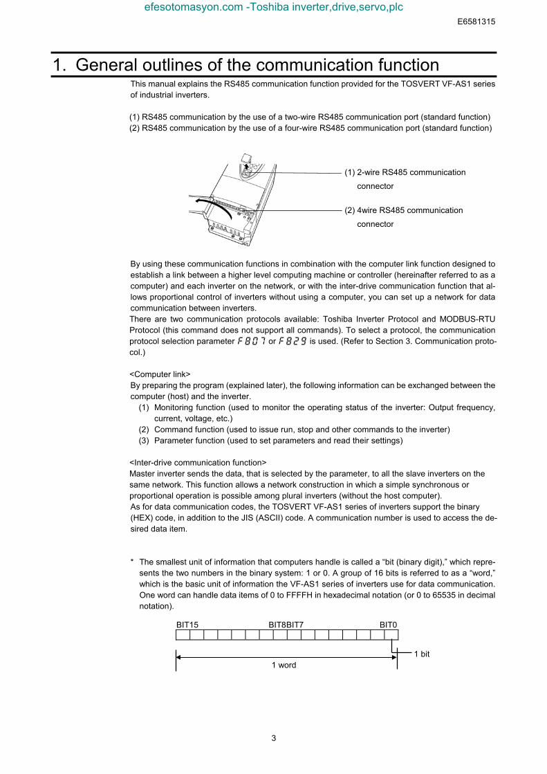
(1) RS485 communication by the use of a two-wire RS485 communication port (standard function)(2) RS485 communication by the use of a four-wire RS485 communication port (standard function)
By using these communication functions in combination with the computer link function designed toestablish a link between a higher level computing machine or controller (hereinafter referred to as acomputer) and each inverter on the network, or with the inter-drive communication function that al-lows proportional control of inverters without using a computer, you can set up a network for datacommunication between inverters.There are two communication protocols available: Toshiba Inverter Protocol and MODBUS-RTUProtocol (this command does not support all commands). To select a protocol, the communicationprotocol selection parameter f807 or f829 is used. (Refer to Section 3. Communication proto-col.)
<Computer link>By preparing the program (explained later), the following information can be exchanged between thecomputer (host) and the inverter.
(1) Monitoring function (used to monitor the operating status of the inverter: Output frequency,current, voltage, etc.)
(2) Command function (used to issue run, stop and other commands to the inverter)(3) Parameter function (used to set parameters and read their settings)
<Inter-drive communication function>Master inverter sends the data, that is selected by the parameter, to all the slave inverters on thesame network. This function allows a network construction in which a simple synchronous orproportional operation is possible among plural inverters (without the host computer).As for data communication codes, the TOSVERT VF-AS1 series of inverters support the binary(HEX) code, in addition to the JIS (ASCII) code. A communication number is used to access the de-sired data item.
* The smallest unit of information that computers handle is called a “bit (binary digit),” which repre-sents the two numbers in the binary system: 1 or 0. A group of 16 bits is referred to as a “word,”which is the basic unit of information the VF-AS1 series of inverters use for data communication.One word can handle data items of 0 to FFFFH in hexadecimal notation (or 0 to 65535 in decimalnotation).
BIT15 BIT8BIT7 BIT0
1 bit1 word
(1) 2-wire RS485 communication
connector
(2) 4wire RS485 communication
connector
efesotomasyon.com -Toshiba inverter,drive,servo,plc
E6581315
4
2. Data transmission specifications
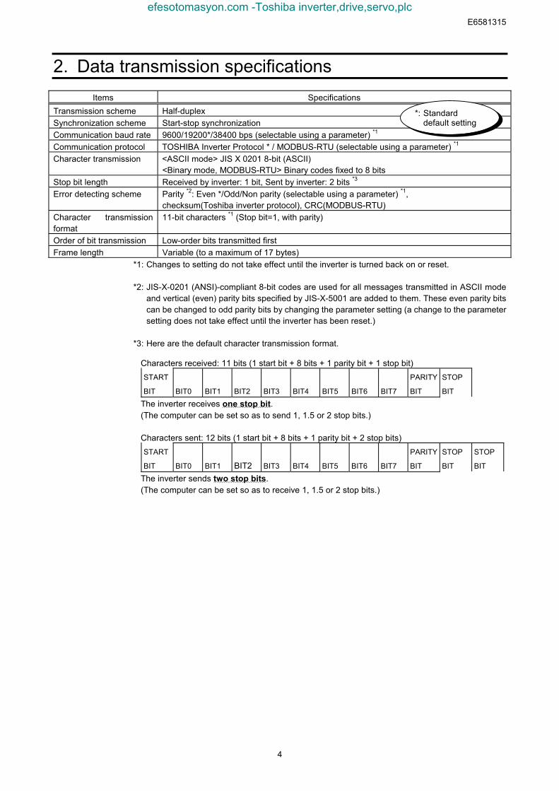
Items SpecificationsTransmission scheme Half-duplexSynchronization scheme Start-stop synchronizationCommunication baud rate 9600/19200*/38400 bps (selectable using a parameter) *1
Communication protocol TOSHIBA Inverter Protocol * / MODBUS-RTU (selectable using a parameter) *1
Character transmission <ASCII mode> JIS X 0201 8-bit (ASCII)<Binary mode, MODBUS-RTU> Binary codes fixed to 8 bits
Stop bit length Received by inverter: 1 bit, Sent by inverter: 2 bits *3
Error detecting scheme Parity *2: Even */Odd/Non parity (selectable using a parameter) *1,checksum(Toshiba inverter protocol), CRC(MODBUS-RTU)
Character transmissionformat
11-bit characters *1 (Stop bit=1, with parity)
Order of bit transmission Low-order bits transmitted firstFrame length Variable (to a maximum of 17 bytes)
*1: Changes to setting do not take effect until the inverter is turned back on or reset.
*2: JIS-X-0201 (ANSI)-compliant 8-bit codes are used for all messages transmitted in ASCII modeand vertical (even) parity bits specified by JIS-X-5001 are added to them. These even parity bitscan be changed to odd parity bits by changing the parameter setting (a change to the parametersetting does not take effect until the inverter has been reset.)
*3: Here are the default character transmission format.
Characters received: 11 bits (1 start bit + 8 bits + 1 parity bit + 1 stop bit)START
BIT BIT0 BIT1 BIT2 BIT3 BIT4 BIT5 BIT6 BIT7
PARITY
BIT
STOP
BIT
The inverter receives one stop bit.(The computer can be set so as to send 1, 1.5 or 2 stop bits.)
Characters sent: 12 bits (1 start bit + 8 bits + 1 parity bit + 2 stop bits)START
BIT BIT0 BIT1 BIT2 BIT3 BIT4 BIT5 BIT6 BIT7
PARITY
BIT
STOP
BIT
STOP
BIT
The inverter sends two stop bits.(The computer can be set so as to receive 1, 1.5 or 2 stop bits.)
*: Standarddefault setting
efesotomasyon.com -Toshiba inverter,drive,servo,plc
E6581315
5
3. Communication protocolThis communication protocol supports the TOSHIBA Inverter Protocol and part of MODBUS-RTUprotocol.
Select the desired protocol from in the following communication protocol selection parameters(, ).
“Parameter Name and , Communication Number. 0807 and 0829”Data Range: 0, 1 (Initial value: 0)0: TOSHIBA (Includes inter-drive communication)1: MOUBUS-RTU
* A parameter change is reflected when the inverter is reset, such as in power off.
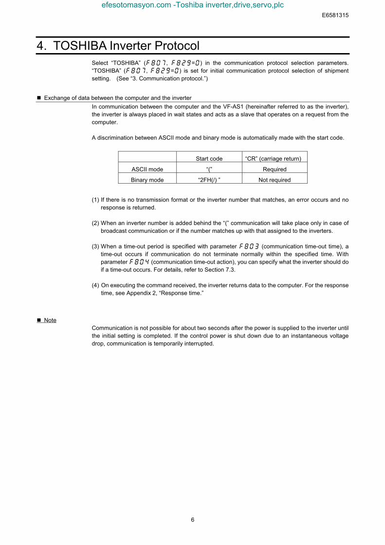
3.1. About the handling of received framesTo send and receive data frames, a frame synchronization system for locating the start and endpoints of each frame is defined with time for which no data is sent (time interval equivalent to thetime required to send 3.5 bytes of data).If no data is sent for the time required to send 3.5 bytes of data at the current transmission speed(approx. 4 ms or more at 9,600 bps or approx. 2 ms or more at 19,200/38,400 bps) after receipt of aframe, the entire frame is assumed to have reached and information in it is analyzed. For this rea-son, an interval corresponding to at least 3.5 bytes of data must be placed between frames.When sending a significant data set using two or more frames, an interval corresponding to at least1.5 bytes of data must be placed between frames. If an interval corresponding to 1.5 bytes or moreis not placed, the contents of a frame are analyzed separately from those of the other frames, andtherefore communication are not carried out normally.When two or more inverters on the same line are controlled individually one after another, not onlydata from the host computer to an inverter but also a response from an inverter to the host computerare transmitted to the other inverters on the line too. Therefore, an interval corresponding to at least3.5 bytes should be placed between the time when the host computer receives a response from aninverter and the time when it sends a frame to the next inverter. Otherwise the return frame receivedand the frame that is sent immediately after receipt of the return frame will be recognized as oneframe and communication will not be carried out normally.
Frame A Frame B
[Correct]
1.5 bytes or more
Frame A (1/2)
[Wrong] If divided into two smaller frames, frame A cannot be received as a
single frame.
Frame A (2/2)
3.5 bytes or more
Frame B
Note: Correct if the interval corresponds
to less than 1.5 bytes of data.
Note: An inverter cannot receive frame
B before it finishes analyzing the
contents of frame A.
efesotomasyon.com -Toshiba inverter,drive,servo,plc
E6581315
6
4. TOSHIBA Inverter ProtocolSelect “TOSHIBA” (, =) in the communication protocol selection parameters.“TOSHIBA” (, =) is set for initial communication protocol selection of shipmentsetting. (See “3. Communication protocol.”)
Exchange of data between the computer and the inverterIn communication between the computer and the VF-AS1 (hereinafter referred to as the inverter),the inverter is always placed in wait states and acts as a slave that operates on a request from thecomputer.
A discrimination between ASCII mode and binary mode is automatically made with the start code.
Start code “CR” (carriage return)
ASCII mode “(” Required
Binary mode “2FH(/) ” Not required
(1) If there is no transmission format or the inverter number that matches, an error occurs and noresponse is returned.
(2) When an inverter number is added behind the “(” communication will take place only in case ofbroadcast communication or if the number matches up with that assigned to the inverters.
(3) When a time-out period is specified with parameter f803 (communication time-out time), atime-out occurs if communication do not terminate normally within the specified time. Withparameter f804 (communication time-out action), you can specify what the inverter should doif a time-out occurs. For details, refer to Section 7.3.
(4) On executing the command received, the inverter returns data to the computer. For the responsetime, see Appendix 2, “Response time.”
NoteCommunication is not possible for about two seconds after the power is supplied to the inverter untilthe initial setting is completed. If the control power is shut down due to an instantaneous voltagedrop, communication is temporarily interrupted.
efesotomasyon.com -Toshiba inverter,drive,servo,plc
E6581315
7
4.1. Data transmission format Note: The term “trip status” used in this manual includes retry waiting status and trip retention status.
4.1.1. Data transmission format used in ASCII modeA communication number is used to specify a data item, all data is written in hexadecimal, and JIS-X-0201 (ASCII (ANSI))-compliant transmission characters are used.
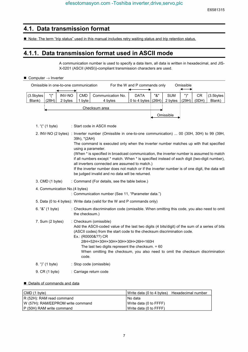
Computer → Inverter
Omissible in one-to-one communication For the W and P commands only Omissible
(3.5bytes Blank)
"("(28H)
INV-NO2 bytes
CMD1 byte
Communication No.4 bytes
DATA0 to 4 bytes
"&"(26H)
SUM2 bytes
")"(29H)
CR (0DH)
(3.5bytesBlank)
Checksum area
Omissible
1. “(“ (1 byte) : Start code in ASCII mode
2. INV-NO (2 bytes) : Inverter number (Omissible in one-to-one communication) ... 00 (30H, 30H) to 99 (39H,39h), *(2AH)The command is executed only when the inverter number matches up with that specifiedusing a parameter.(When * is specified in broadcast communication, the inverter number is assumed to matchif all numbers except * match. When * is specified instead of each digit (two-digit number),all inverters connected are assumed to match.)If the inverter number does not match or if the inverter number is of one digit, the data willbe judged invalid and no data will be returned.
3. CMD (1 byte) : Command (For details, see the table below.)
4. Communication No.(4 bytes): Communication number (See 11, “Parameter data.”)
5. Data (0 to 4 bytes): Write data (valid for the W and P commands only)
6. “&” (1 byte) : Checksum discrimination code (omissible. When omitting this code, you also need to omitthe checksum.)
7. Sum (2 bytes) : Checksum (omissible)Add the ASCII-coded value of the last two digits (4 bits/digit) of the sum of a series of bits(ASCII codes) from the start code to the checksum discrimination code.Ex.: (R0000&??) CR
28H+52H+30H+30H+30H+30H+26H=160HThe last two digits represent the checksum. = 60When omitting the checksum, you also need to omit the checksum discriminationcode.
8. “)” (1 byte) : Stop code (omissible)
9. CR (1 byte) : Carriage return code
Details of commands and data
CMD (1 byte) Write data (0 to 4 bytes) Hexadecimal numberR (52H): RAM read commandW (57H): RAM/EEPROM write commandP (50H) RAM write command
No dataWrite data (0 to FFFF)Write data (0 to FFFF)
efesotomasyon.com -Toshiba inverter,drive,servo,plc
E6581315
8
Inverter → computer
At time of broadcast communication, returning of data is not executed, except for the inverters to be
returned, when the inverter number is not matched, and the inverter number has only one character.
This is because there will be a risk of that the returned data may be deformed.
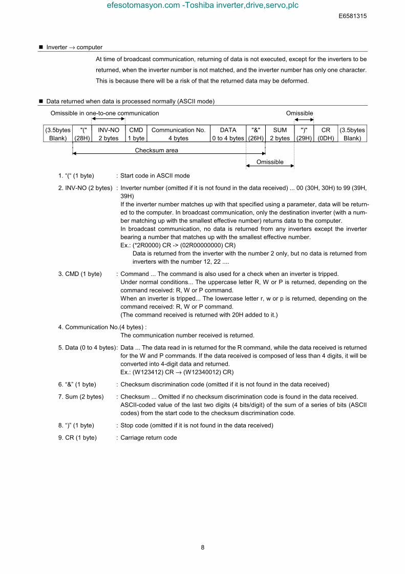
Data returned when data is processed normally (ASCII mode)
Omissible in one-to-one communication Omissible
(3.5bytesBlank)
"("(28H)
INV-NO2 bytes
CMD1 byte
Communication No.4 bytes
DATA0 to 4 bytes
"&"(26H)
SUM2 bytes
")"(29H)
CR (0DH)
(3.5bytesBlank)
Checksum area
Omissible
1. “(“ (1 byte) : Start code in ASCII mode
2. INV-NO (2 bytes) : Inverter number (omitted if it is not found in the data received) ... 00 (30H, 30H) to 99 (39H,39H)If the inverter number matches up with that specified using a parameter, data will be return-ed to the computer. In broadcast communication, only the destination inverter (with a num-ber matching up with the smallest effective number) returns data to the computer.In broadcast communication, no data is returned from any inverters except the inverterbearing a number that matches up with the smallest effective number.Ex.: (*2R0000) CR -> (02R00000000) CR)
Data is returned from the inverter with the number 2 only, but no data is returned frominverters with the number 12, 22 ....
3. CMD (1 byte) : Command ... The command is also used for a check when an inverter is tripped.Under normal conditions... The uppercase letter R, W or P is returned, depending on thecommand received: R, W or P command.When an inverter is tripped... The lowercase letter r, w or p is returned, depending on thecommand received: R, W or P command.(The command received is returned with 20H added to it.)
4. Communication No.(4 bytes) :The communication number received is returned.
5. Data (0 to 4 bytes): Data ... The data read in is returned for the R command, while the data received is returnedfor the W and P commands. If the data received is composed of less than 4 digits, it will beconverted into 4-digit data and returned.Ex.: (W123412) CR → (W12340012) CR)
6. “&” (1 byte) : Checksum discrimination code (omitted if it is not found in the data received)
7. Sum (2 bytes) : Checksum ... Omitted if no checksum discrimination code is found in the data received.ASCII-coded value of the last two digits (4 bits/digit) of the sum of a series of bits (ASCIIcodes) from the start code to the checksum discrimination code.
8. “)” (1 byte) : Stop code (omitted if it is not found in the data received)
9. CR (1 byte) : Carriage return code
efesotomasyon.com -Toshiba inverter,drive,servo,plc

E6581315
9
• Data returned when data is not processed normally (ASCII mode)In case an error occurs, communication error command (4EH(N) or 6EH(n)) and the error type num-ber is returned to the computer in addition to the checksum. At time of broadcast communication ofthe binary mode, returning of data is not executed except for the inverter to be returned (inverternumber 00H) and when the inverter number is not matched. This is because there will be a risk thatthe returned data may be deformed.
Omissible Omissible
(3.5bytesBlank)
“(“(28H)
INV-NO2 bytes
“N” or “n”(4EH) (6EH)
DATA4 bytes
"&"(26H)
SUM2 bytes
")"(29H)
CR(0DH)
(3.5bytesBlank)
Checksum area
Omissible
“(“ (1 byte) : Start code in ASCII mode
“N” or “n” (1 byte) :Communication error command ... This is also used for the checking of inverter trip.
“N” for the normal communication and “n” during the inverter trip.
INV-NO (2 bytes) : Inverter number (omitted if it is not found in the data received) ... 00 (30H, 30H) to 99 (39H,39H)If the inverter number matches up with that specified using a parameter, data will be return-ed to the computer. In broadcast communication, only the destination inverter (with a num-ber matching up with the smallest effective number) returns data to the computer.
Data (4 bytes) : Error code (0000~0004)0000 ... Impossible to execute (Although communication is established normally, the
command cannot be executed because it is to write data into a parameter whosesetting cannot be changed during operation (e.g., maximum frequency) or theEEPROM is faulty.)
0001 ... Data error (The data is outside the specified range or it is composed of too manydigits.)
0002 ... Communication number error (There is no communication number that matches.)0003 ... Command error (There is no command that matches.)0004 ... Checksum error (The checksum result differs.)
“)” (1 byte) : Stop code ... This code is omitted if it is not found in the data received.
Examples:(N0000&5C)CR... Impossible to execute (e.g., a change of maximum frequency data during opera-
tion)(N0001&5D)CR... Data error (Data is outside the specified range.)(N0002&5E)CR... No communication number (There is no communication number that matches.)(N0003&5F)CR... There is no command that matches. (Commands other than the R, W and P
commands)(Ex.: L, S, G, a, b, m, r, t, w ...)
(N0004&60)CR... Checksum error (The checksum result differs.)No data returned ... Format error or invalid inverter number
efesotomasyon.com -Toshiba inverter,drive,servo,plc

E6581315
10
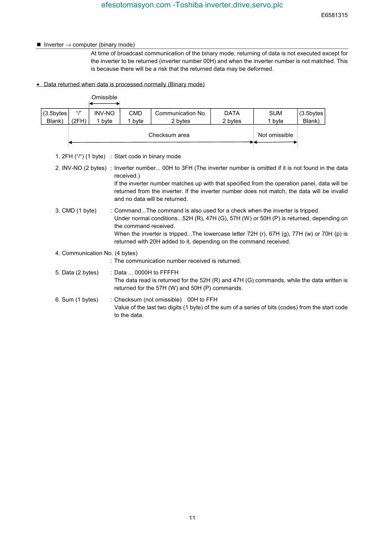
4.1.2. Data transmission format used in binary modeA communication number is used to specify a data item, data is written in hexadecimal form, anddata in transmission characters are represented by binary codes (HEX codes).
Computer → Inverter (binary mode)
Omissible in one-to-one communication No data for the 52H (R) command
(3.5bytesBlank)
“/”(2FH)
INV-NO1 byte
CMD1 byte
Communication No.2 bytes
DATA2 bytes
SUM1 byte
(3.5bytesBlank)
Checksum area Not omissible
1. 2FH (“/”) (1 byte) : Start code in binary mode
2. INV-NO (2 bytes) : Inverter number (Omissible in one-to-one communication) ... 00H to 3FH ,FFH
In case the inverter number is other than FFH (broadcast communication), command is ex-
ecuted only when the inverter number coincides with the one designated with the panel. If
the inverter number is not matched, it will be judged invalid and the data is not returned.
3. CMD (1 byte) : Command (For details, see the table below.)52H (R) command: The size of the data following CMD is fixed to 3 bytes. (Communicationnumber: 2 bytes, checksum: 1 byte)57H (W), 50H (P) and 47H (G) commands: The size of the data following CMD is fixed to 5bytes.(Communication number: 2 bytes, data: 2 byte, checksum: 1 byte)Any command other than the above is rejected and no error code is returned.
4. Communication No.(2 bytes): Communication number (See 11, “Parameter data.”)
5. Data (2 bytes) : 0000H to FFFFH57H (W) and 50H (P) commands: Write data (An area check is performed.)47H (G) command: Dummy data (e.g., 0000) is needed.52H (R) command: Any data is judged invalid. (No data should be added.)
6. Sum (2 bytes) : Checksum (not omissible) 00H to FFHValue of the last two digits (1 byte) of the sum of a series of bits (codes) from the start codeof the data returned to the data (or to the communication number for the 52H (R) com-mand)Ex.: 2F 52 00 ?? ... 2FH+52H+00H+00H=81HThe last two digits (??) represent the checksum= 81
Details of commands and data
CMD (1 byte) Write data (2 bytes) Hexadecimal number52H (R): RAM read command57H (W): RAM/EEPROM write command50H (P): RAM write command47H (G): RAM read command (for two-wire networks)
No dataWrite data (0000H to FFFFH)Write data (0000H to FFFFH)Dummy data (0000H to FFFFH)
efesotomasyon.com -Toshiba inverter,drive,servo,plc
E6581315
11
Inverter → computer (binary mode)At time of broadcast communication of the binary mode, returning of data is not executed except forthe inverter to be returned (inverter number 00H) and when the inverter number is not matched. Thisis because there will be a risk that the returned data may be deformed.
• Data returned when data is processed normally (Binary mode)
Omissible
(3.5bytesBlank)
“/”(2FH)
INV-NO1 byte
CMD1 byte
Communication No.2 bytes
DATA2 bytes
SUM1 byte
(3.5bytesBlank)
Checksum area Not omissible
1. 2FH (“/“) (1 byte) : Start code in binary mode
2. INV-NO (2 bytes) : Inverter number... 00H to 3FH (The inverter number is omitted if it is not found in the datareceived.)If the inverter number matches up with that specified from the operation panel, data will bereturned from the inverter. If the inverter number does not match, the data will be invalidand no data will be returned.
3. CMD (1 byte) : Command...The command is also used for a check when the inverter is tripped.Under normal conditions...52H (R), 47H (G), 57H (W) or 50H (P) is returned, depending onthe command received.When the inverter is tripped...The lowercase letter 72H (r), 67H (g), 77H (w) or 70H (p) isreturned with 20H added to it, depending on the command received.
4. Communication No. (4 bytes): The communication number received is returned.
5. Data (2 bytes) : Data ... 0000H to FFFFHThe data read is returned for the 52H (R) and 47H (G) commands, while the data written isreturned for the 57H (W) and 50H (P) commands.
6. Sum (1 bytes) : Checksum (not omissible) 00H to FFHValue of the last two digits (1 byte) of the sum of a series of bits (codes) from the start codeto the data.
efesotomasyon.com -Toshiba inverter,drive,servo,plc
E6581315
12
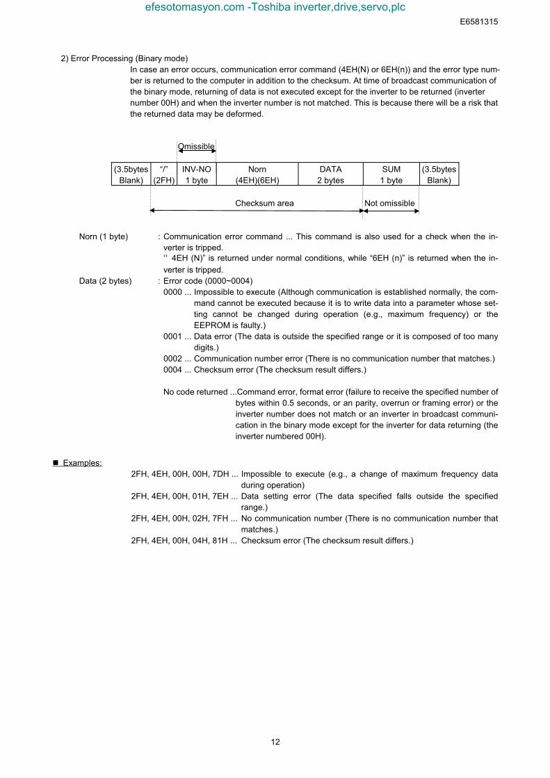
2) Error Processing (Binary mode)In case an error occurs, communication error command (4EH(N) or 6EH(n)) and the error type num-ber is returned to the computer in addition to the checksum. At time of broadcast communication ofthe binary mode, returning of data is not executed except for the inverter to be returned (inverternumber 00H) and when the inverter number is not matched. This is because there will be a risk thatthe returned data may be deformed.
Omissible
(3.5bytesBlank)
“/”(2FH)
INV-NO1 byte
Norn(4EH)(6EH)
DATA2 bytes
SUM1 byte
(3.5bytesBlank)
Checksum area Not omissible
Norn (1 byte) : Communication error command ... This command is also used for a check when the in-verter is tripped.“4EH (N)” is returned under normal conditions, while “6EH (n)” is returned when the in-verter is tripped.
Data (2 bytes) : Error code (0000~0004)0000 ... Impossible to execute (Although communication is established normally, the com-
mand cannot be executed because it is to write data into a parameter whose set-ting cannot be changed during operation (e.g., maximum frequency) or theEEPROM is faulty.)
0001 ... Data error (The data is outside the specified range or it is composed of too manydigits.)
0002 ... Communication number error (There is no communication number that matches.)0004 ... Checksum error (The checksum result differs.)
No code returned ...Command error, format error (failure to receive the specified number ofbytes within 0.5 seconds, or an parity, overrun or framing error) or theinverter number does not match or an inverter in broadcast communi-cation in the binary mode except for the inverter for data returning (theinverter numbered 00H).
Examples:2FH, 4EH, 00H, 00H, 7DH ... Impossible to execute (e.g., a change of maximum frequency data
during operation)2FH, 4EH, 00H, 01H, 7EH ... Data setting error (The data specified falls outside the specified
range.)2FH, 4EH, 00H, 02H, 7FH ... No communication number (There is no communication number that
matches.)2FH, 4EH, 00H, 04H, 81H ... Checksum error (The checksum result differs.)
efesotomasyon.com -Toshiba inverter,drive,servo,plc
E6581315
13
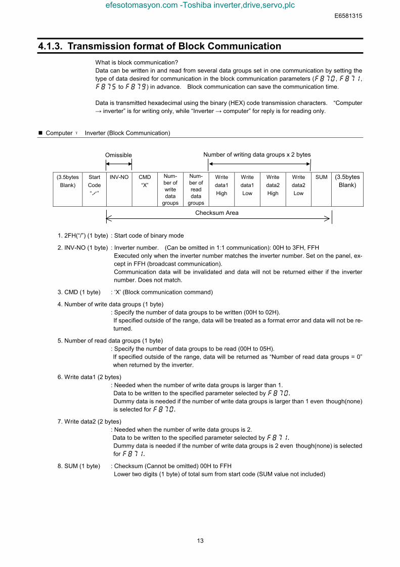
4.1.3. Transmission format of Block CommunicationWhat is block communication?Data can be written in and read from several data groups set in one communication by setting thetype of data desired for communication in the block communication parameters (, , to ) in advance. Block communication can save the communication time.
Data is transmitted hexadecimal using the binary (HEX) code transmission characters. “Computer→ inverter” is for writing only, while “Inverter → computer” for reply is for reading only.
Computer → Inverter (Block Communication)
1. 2FH(“/”) (1 byte) : Start code of binary mode
2. INV-NO (1 byte) : Inverter number. (Can be omitted in 1:1 communication): 00H to 3FH, FFHExecuted only when the inverter number matches the inverter number. Set on the panel, ex-cept in FFH (broadcast communication).Communication data will be invalidated and data will not be returned either if the inverternumber. Does not match.
3. CMD (1 byte) : ‘X’ (Block communication command)
4. Number of write data groups (1 byte): Specify the number of data groups to be written (00H to 02H).If specified outside of the range, data will be treated as a format error and data will not be re-turned.
5. Number of read data groups (1 byte): Specify the number of data groups to be read (00H to 05H).If specified outside of the range, data will be returned as “Number of read data groups = 0”when returned by the inverter.
6. Write data1 (2 bytes): Needed when the number of write data groups is larger than 1.Data to be written to the specified parameter selected by Dummy data is needed if the number of write data groups is larger than 1 even though(none)is selected for
7. Write data2 (2 bytes): Needed when the number of write data groups is 2.Data to be written to the specified parameter selected by Dummy data is needed if the number of write data groups is 2 even though(none) is selectedfor
8. SUM (1 byte) : Checksum (Cannot be omitted) 00H to FFHLower two digits (1 byte) of total sum from start code (SUM value not included)
(3.5bytesBlank)
StartCode“/”
INV-NO CMD“X”
Num-ber ofwritedata
groups
Num-ber ofreaddata
groups
Writedata1High
Writedata1Low
Writedata2High
Writedata2Low
SUM (3.5bytesBlank)
Checksum Area
Omissible Number of writing data groups x 2 bytes
efesotomasyon.com -Toshiba inverter,drive,servo,plc
E6581315
14
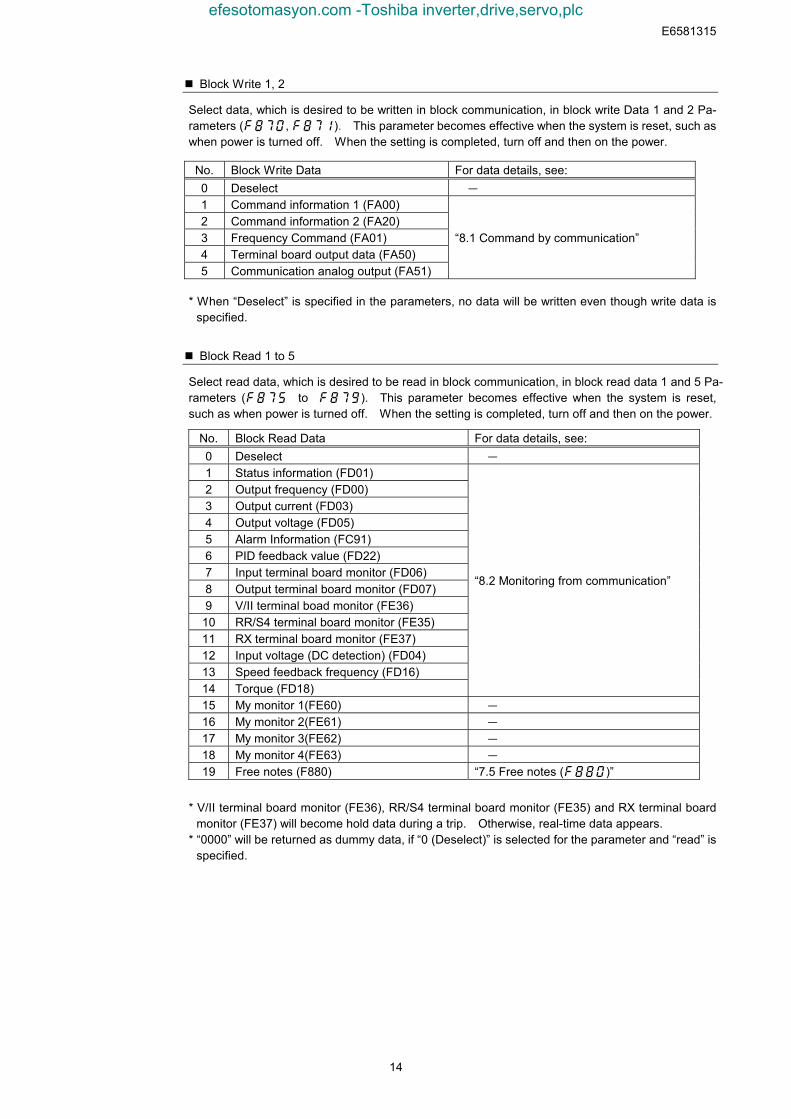
Block Write 1, 2
Select data, which is desired to be written in block communication, in block write Data 1 and 2 Pa-rameters (, ). This parameter becomes effective when the system is reset, such aswhen power is turned off. When the setting is completed, turn off and then on the power.
* When “Deselect” is specified in the parameters, no data will be written even though write data isspecified.
Block Read 1 to 5
Select read data, which is desired to be read in block communication, in block read data 1 and 5 Pa-rameters (to). This parameter becomes effective when the system is reset,such as when power is turned off. When the setting is completed, turn off and then on the power.
* V/II terminal board monitor (FE36), RR/S4 terminal board monitor (FE35) and RX terminal boardmonitor (FE37) will become hold data during a trip. Otherwise, real-time data appears.
* “0000” will be returned as dummy data, if “0 (Deselect)” is selected for the parameter and “read” isspecified.
No. Block Write Data For data details, see:0 Deselect -
1 Command information 1 (FA00)2 Command information 2 (FA20)3 Frequency Command (FA01)4 Terminal board output data (FA50)5 Communication analog output (FA51)
“8.1 Command by communication”
No. Block Read Data For data details, see:0 Deselect -
1 Status information (FD01)2 Output frequency (FD00)3 Output current (FD03)4 Output voltage (FD05)5 Alarm Information (FC91)6 PID feedback value (FD22)7 Input terminal board monitor (FD06)8 Output terminal board monitor (FD07)9 V/II terminal boad monitor (FE36)
10 RR/S4 terminal board monitor (FE35)11 RX terminal board monitor (FE37)12 Input voltage (DC detection) (FD04)13 Speed feedback frequency (FD16)14 Torque (FD18)
“8.2 Monitoring from communication”
15 My monitor 1(FE60) -
16 My monitor 2(FE61) -
17 My monitor 3(FE62) -
18 My monitor 4(FE63) -
19 Free notes (F880) “7.5 Free notes ()”
efesotomasyon.com -Toshiba inverter,drive,servo,plc
E6581315
15
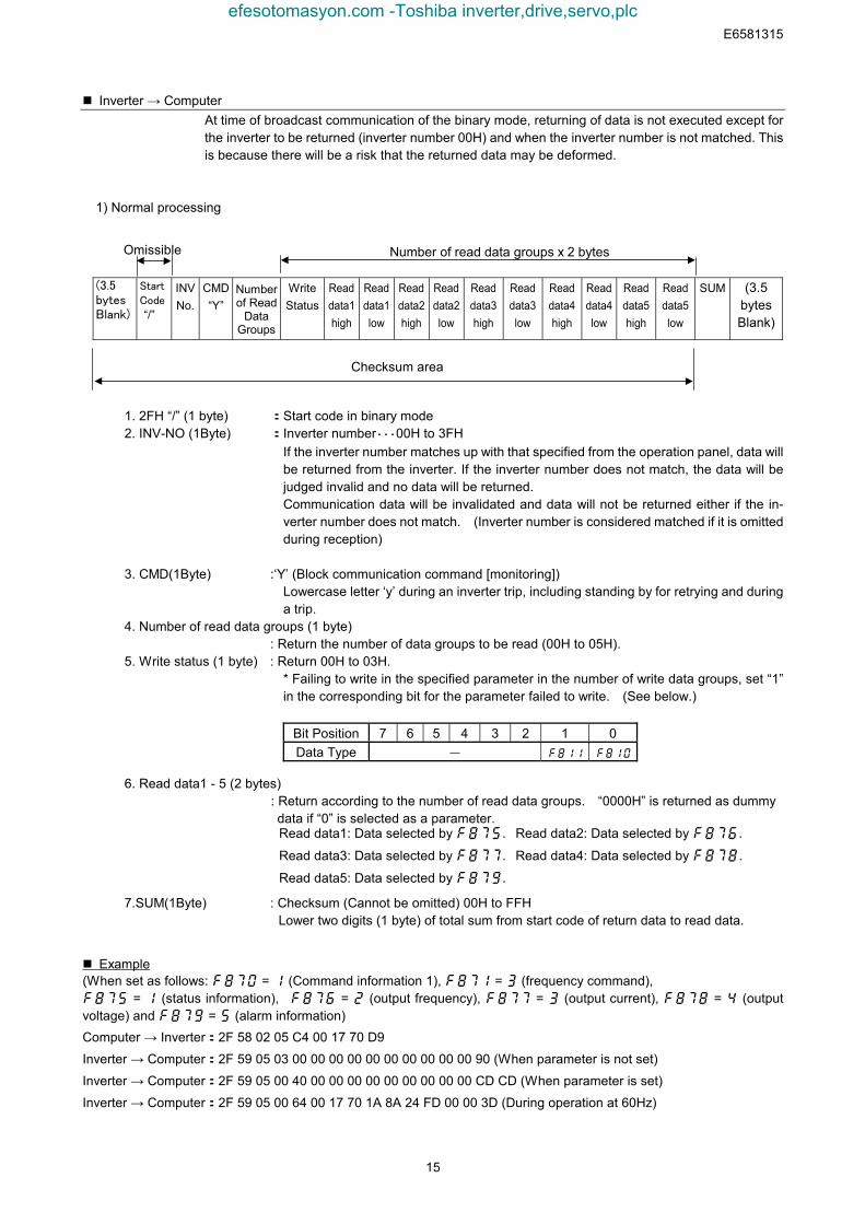
Inverter → ComputerAt time of broadcast communication of the binary mode, returning of data is not executed except forthe inverter to be returned (inverter number 00H) and when the inverter number is not matched. Thisis because there will be a risk that the returned data may be deformed.
1) Normal processing
1. 2FH “/” (1 byte) :Start code in binary mode2. INV-NO (1Byte) :Inverter number・・・00H to 3FH
If the inverter number matches up with that specified from the operation panel, data willbe returned from the inverter. If the inverter number does not match, the data will bejudged invalid and no data will be returned.Communication data will be invalidated and data will not be returned either if the in-verter number does not match. (Inverter number is considered matched if it is omittedduring reception)
3. CMD(1Byte) :‘Y’ (Block communication command [monitoring])Lowercase letter ‘y’ during an inverter trip, including standing by for retrying and duringa trip.
4. Number of read data groups (1 byte): Return the number of data groups to be read (00H to 05H).
5. Write status (1 byte) : Return 00H to 03H.* Failing to write in the specified parameter in the number of write data groups, set “1”in the corresponding bit for the parameter failed to write. (See below.)
6. Read data1 - 5 (2 bytes): Return according to the number of read data groups. “0000H” is returned as dummy data if “0” is selected as a parameter.
Read data1: Data selected by . Read data2: Data selected by .
Read data3: Data selected by . Read data4: Data selected by .
Read data5: Data selected by .
7.SUM(1Byte) : Checksum (Cannot be omitted) 00H to FFHLower two digits (1 byte) of total sum from start code of return data to read data.
Example(When set as follows: = (Command information 1), = (frequency command), = (status information), = (output frequency), = (output current), = (outputvoltage) and = (alarm information)Computer → Inverter:2F 58 02 05 C4 00 17 70 D9
Inverter → Computer:2F 59 05 03 00 00 00 00 00 00 00 00 00 00 90 (When parameter is not set)
Inverter → Computer:2F 59 05 00 40 00 00 00 00 00 00 00 00 00 CD CD (When parameter is set)
Inverter → Computer:2F 59 05 00 64 00 17 70 1A 8A 24 FD 00 00 3D (During operation at 60Hz)
(3.5bytesBlank)
StartCode“/”
INVNo.
CMD“Y”
Numberof Read
DataGroups
WriteStatus
Readdata1high
Readdata1low
Readdata2high
Readdata2low
Readdata3high
Readdata3low
Readdata4high
Readdata4low
Readdata5high
Readdata5low
SUM (3.5bytesBlank)
Checksum area
Omissible Number of read data groups x 2 bytes
Bit Position 7 6 5 4 3 2 1 0Data Type -
efesotomasyon.com -Toshiba inverter,drive,servo,plc
E6581315
16
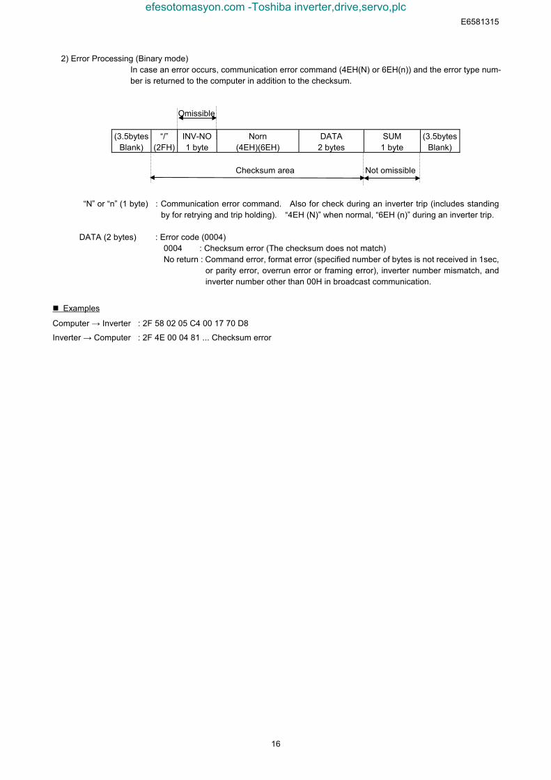
2) Error Processing (Binary mode)In case an error occurs, communication error command (4EH(N) or 6EH(n)) and the error type num-ber is returned to the computer in addition to the checksum.
Omissible
(3.5bytesBlank)
“/”(2FH)
INV-NO1 byte
Norn(4EH)(6EH)
DATA2 bytes
SUM1 byte
(3.5bytesBlank)
Checksum area Not omissible
“N” or “n” (1 byte) : Communication error command. Also for check during an inverter trip (includes standingby for retrying and trip holding). “4EH (N)” when normal, “6EH (n)” during an inverter trip.
DATA (2 bytes) : Error code (0004) 0004 : Checksum error (The checksum does not match) No return : Command error, format error (specified number of bytes is not received in 1sec,
or parity error, overrun error or framing error), inverter number mismatch, andinverter number other than 00H in broadcast communication.
Examples
Computer → Inverter : 2F 58 02 05 C4 00 17 70 D8
Inverter → Computer : 2F 4E 00 04 81 ... Checksum error
efesotomasyon.com -Toshiba inverter,drive,servo,plc
E6581315
17
4.2. CommandsHere are the communication commands available.Command Function
R command Reads the data with the specified communication number.W command Writes the data with the specified communication number. (RAM and EEPROM).P command Writes the data with the specified communication number. (RAM).
G commandReads the data with the specified communication number. (For binary mode only.Dummy data is required for this command.)
X command Block communication (Computer -> Inverter)Y command Block communication (Inverter -> Computer)
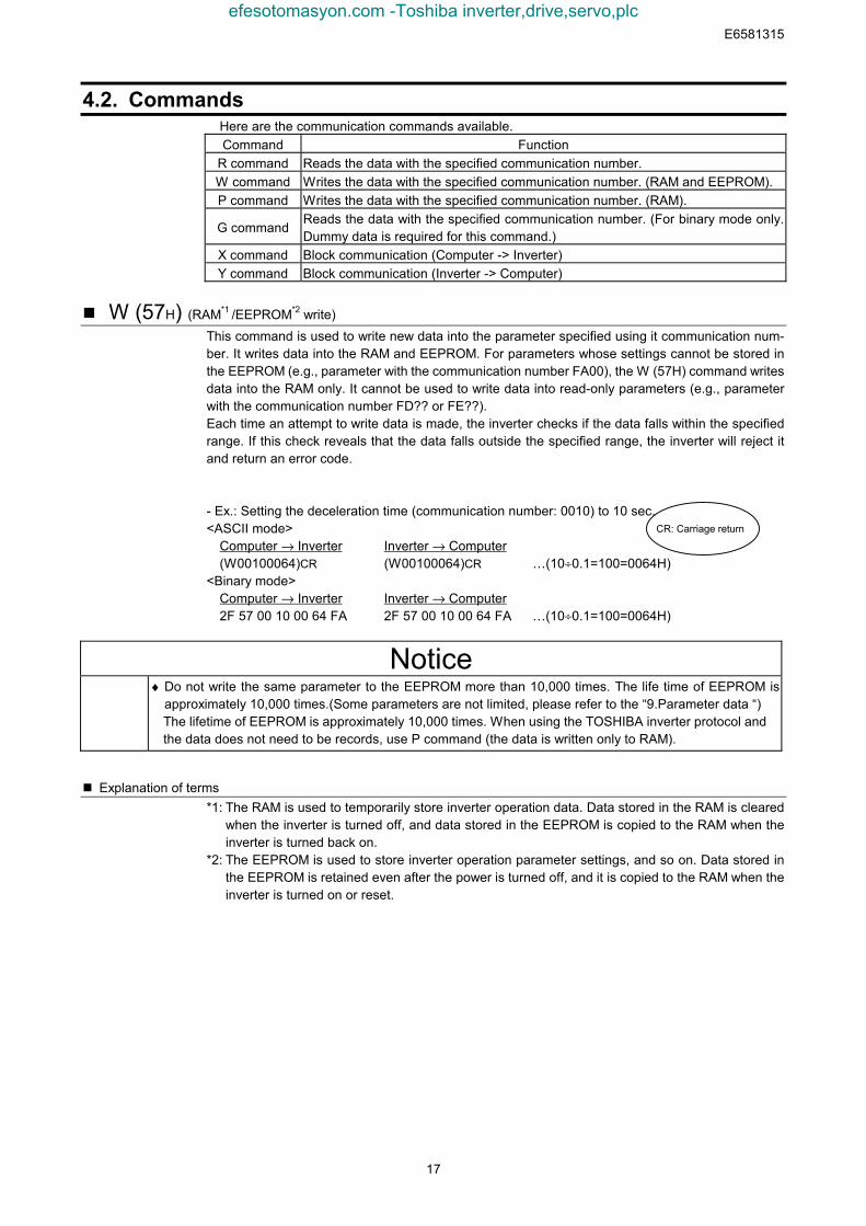
W (57H) (RAM*1 /EEPROM*2 write)This command is used to write new data into the parameter specified using it communication num-ber. It writes data into the RAM and EEPROM. For parameters whose settings cannot be stored inthe EEPROM (e.g., parameter with the communication number FA00), the W (57H) command writesdata into the RAM only. It cannot be used to write data into read-only parameters (e.g., parameterwith the communication number FD?? or FE??).Each time an attempt to write data is made, the inverter checks if the data falls within the specifiedrange. If this check reveals that the data falls outside the specified range, the inverter will reject itand return an error code.
- Ex.: Setting the deceleration time (communication number: 0010) to 10 sec.<ASCII mode>
Computer → Inverter Inverter → Computer(W00100064)CR (W00100064)CR …(10÷0.1=100=0064H)
<Binary mode>Computer → Inverter Inverter → Computer2F 57 00 10 00 64 FA 2F 57 00 10 00 64 FA …(10÷0.1=100=0064H)
Notice♦ Do not write the same parameter to the EEPROM more than 10,000 times. The life time of EEPROM is
approximately 10,000 times.(Some parameters are not limited, please refer to the “9.Parameter data “)The lifetime of EEPROM is approximately 10,000 times. When using the TOSHIBA inverter protocol andthe data does not need to be records, use P command (the data is written only to RAM).
Explanation of terms*1: The RAM is used to temporarily store inverter operation data. Data stored in the RAM is cleared
when the inverter is turned off, and data stored in the EEPROM is copied to the RAM when theinverter is turned back on.
*2: The EEPROM is used to store inverter operation parameter settings, and so on. Data stored inthe EEPROM is retained even after the power is turned off, and it is copied to the RAM when theinverter is turned on or reset.
CR: Carriage return
efesotomasyon.com -Toshiba inverter,drive,servo,plc
E6581315
18
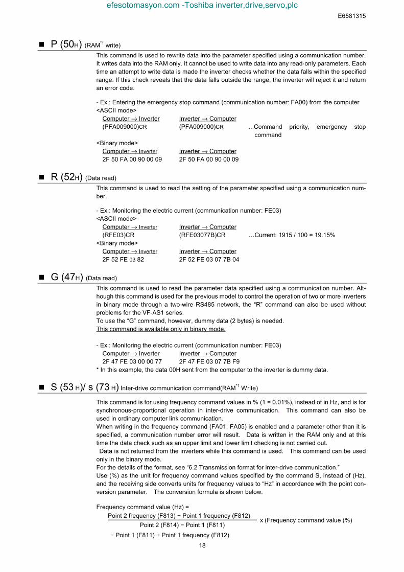
P (50H) (RAM*1 write)This command is used to rewrite data into the parameter specified using a communication number.It writes data into the RAM only. It cannot be used to write data into any read-only parameters. Eachtime an attempt to write data is made the inverter checks whether the data falls within the specifiedrange. If this check reveals that the data falls outside the range, the inverter will reject it and returnan error code.
- Ex.: Entering the emergency stop command (communication number: FA00) from the computer<ASCII mode>
Computer → Inverter Inverter → Computer(PFA009000)CR (PFA009000)CR …Command priority, emergency stop
command<Binary mode>
Computer → Inverter Inverter → Computer2F 50 FA 00 90 00 09 2F 50 FA 00 90 00 09
R (52H) (Data read)This command is used to read the setting of the parameter specified using a communication num-ber.
- Ex.: Monitoring the electric current (communication number: FE03)<ASCII mode>
Computer → Inverter Inverter → Computer(RFE03)CR (RFE03077B)CR …Current: 1915 / 100 = 19.15%
<Binary mode>Computer → Inverter Inverter → Computer2F 52 FE 03 82 2F 52 FE 03 07 7B 04
G (47H) (Data read) This command is used to read the parameter data specified using a communication number. Alt-hough this command is used for the previous model to control the operation of two or more invertersin binary mode through a two-wire RS485 network, the “R” command can also be used withoutproblems for the VF-AS1 series.To use the “G” command, however, dummy data (2 bytes) is needed. This command is available only in binary mode.
- Ex.: Monitoring the electric current (communication number: FE03)Computer → Inverter Inverter → Computer2F 47 FE 03 00 00 77 2F 47 FE 03 07 7B F9
* In this example, the data 00H sent from the computer to the inverter is dummy data.
S (53 H)/ s (73 H) Inter-drive communication command(RAM*1 Write)
This command is for using frequency command values in % (1 = 0.01%), instead of in Hz, and is forsynchronous-proportional operation in inter-drive communication. This command can also beused in ordinary computer link communication.When writing in the frequency command (FA01, FA05) is enabled and a parameter other than it isspecified, a communication number error will result. Data is written in the RAM only and at thistime the data check such as an upper limit and lower limit checking is not carried out. Data is not returned from the inverters while this command is used. This command can be usedonly in the binary mode.For the details of the format, see “6.2 Transmission format for inter-drive communication.”Use (%) as the unit for frequency command values specified by the command S, instead of (Hz),and the receiving side converts units for frequency values to “Hz” in accordance with the point con-version parameter. The conversion formula is shown below.
Frequency command value (Hz) =Point 2 frequency (F813) − Point 1 frequency (F812)
Point 2 (F814) − Point 1 (F811)x (Frequency command value (%)
− Point 1 (F811) + Point 1 frequency (F812)
efesotomasyon.com -Toshiba inverter,drive,servo,plc
E6581315
19
When Command “s” (lowercase letter) is received, the slave side judges that the master side istripped and operates in accordance with the inter-drive communication parameter (,).For detail, see "7. Communication parameters ".
- Examples: 50% frequency command (2-wire RS485 communication)(If maximum frequency = Frequency for operation at 80Hz = 40Hz: 50% = 5000d = 1388H)
<Binary mode>
Master inverter → Slave inverter Slave inverter → Master inverter2F 53 FA 01 13 88 18 No return
X(58H)/Y (59H) (Block Communication Command)
Data selected in the block communication write parameters (,) is written in theRAM. When returning data, data selected in block communication read parameters ( to) is read and is returned.
For detail, see "4.1.3. Transmission format of Block Communication ".
- Examples: 60Hz operation command from communication and monitoring (Monitoring when al-ready operating at 60Hz)(Parameter Setting: = , = , = , = , = , =, = )
<Binary mode>Computer → Inverter Inverter → Computer2F 58 02 05 C4 00 17 70 D9 2F 59 05 00 64 00 17 70 1A 8A 24 FD 00 00 3D
efesotomasyon.com -Toshiba inverter,drive,servo,plc
E6581315
20
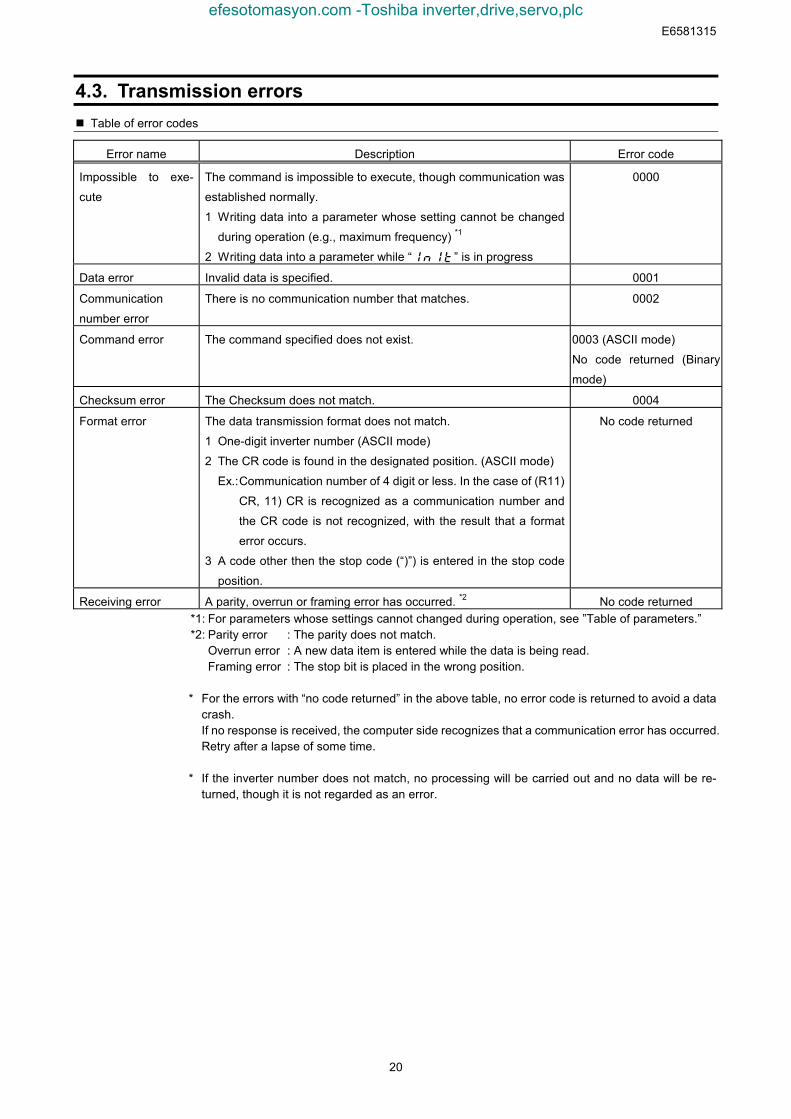
4.3. Transmission errors Table of error codes
Error name Description Error code
Impossible to exe-
cute
The command is impossible to execute, though communication was
established normally.
1 Writing data into a parameter whose setting cannot be changed
during operation (e.g., maximum frequency) *1
2 Writing data into a parameter while “” is in progress
0000
Data error Invalid data is specified. 0001
Communication
number error
There is no communication number that matches. 0002
Command error The command specified does not exist. 0003 (ASCII mode)
No code returned (Binary
mode)
Checksum error The Checksum does not match. 0004
Format error The data transmission format does not match.
1 One-digit inverter number (ASCII mode)
2 The CR code is found in the designated position. (ASCII mode)
Ex.:Communication number of 4 digit or less. In the case of (R11)
CR, 11) CR is recognized as a communication number and
the CR code is not recognized, with the result that a format
error occurs.
3 A code other then the stop code (“)”) is entered in the stop code
position.
No code returned
Receiving error A parity, overrun or framing error has occurred. *2 No code returned*1: For parameters whose settings cannot changed during operation, see ”Table of parameters.”*2: Parity error : The parity does not match.
Overrun error : A new data item is entered while the data is being read.Framing error : The stop bit is placed in the wrong position.
* For the errors with “no code returned” in the above table, no error code is returned to avoid a datacrash.If no response is received, the computer side recognizes that a communication error has occurred.Retry after a lapse of some time.
* If the inverter number does not match, no processing will be carried out and no data will be re-turned, though it is not regarded as an error.
efesotomasyon.com -Toshiba inverter,drive,servo,plc
E6581315
21
4.4. Broadcast communication functionBroadcast communication function can transmit the command (write the data) to multiple invertersby one communication. Only the write (W, P) command is valid and the read (R, G) command is in-valid. The inverters subject to the broadcast communication are the same to the independent com-munication; 0 to 99 (00H - 63H) in the ASCII mode, and 0 to 63 (00H - 3FH) in the binary mode. Toavoid data deforming, the inverters to return data will be limited.
“Overall” broadcast communication (ASCII mode / Binary mode)- ASCII ModeIf you enter two asterisks (**) in the inverter number position of the data transmission format, thecomputer will send the data simultaneously to all inverters (with an inverter number between 0 and99 (00 to 63H)) on the network.
- Binary Mode
To put "FF" to the specified place of the inverter number in the communication format validates the
broadcast communication and the command is transmitted to all the applicable inverters in the net-
work (inverter numbers from 0 to 63 (00 to 3FH)).
<Inverter that returns data to the computer>Data is returned from the inverter bearing the inverter number 00 only.If you do not want inverters to return data, do not assign the number 00 to any inverter on the net-work.
“Group” broadcast communication (ASCII mode only)If you put “*?” In the inverter number position of the data transmission format, data will be sentsimultaneously to all inverters bearing a number whose digit in the one’s place in decimal notationis”?”If you put ”?*” In the inverter number position of the data transmission format, the data will be sentsimultaneously to all inverters bearing a number whose digit in the ten’s place in decimal notationis”?”.(“?”: Any number between 0 and 9.)
<Inverter that returns data to the computer>Data is returned only from the inverter bearing the smallest number in the same group of inverters(i.e., inverter whose number in the position of ”*” is 0).If you do not want inverters to return data to the computer, do not assign a number having a 0 in theposition of “*” to any inverter on the network.)
Examples of broadcast communicationEx: Set the frequency setting for communication to 60Hz.
1 Host computer → Multiple inverters: broadcast communication (ASCII Mode)Example of transmission of data from host computer to inverter: (**PFA011770)CR
Example of data returned from inverter to host computer: (00PFA011770)CR
Data is returned from the inverter numbered 00 only, while commands are issued to all invertersconnected to the network.
2 Host computer → A specific group of inverters: group communication (ASCII Mode)Example of transmission of data from host computer to inverters: (*9PFA011770)CR
Example of data returned from inverter to host computer: (09PFA011770)CR
Data is returned only the inverter numbered 09 only, while commands are issued to a maximumof 10 inverters bearing the number 09, 19, 29, 39, ... or 99.
efesotomasyon.com -Toshiba inverter,drive,servo,plc
E6581315
22
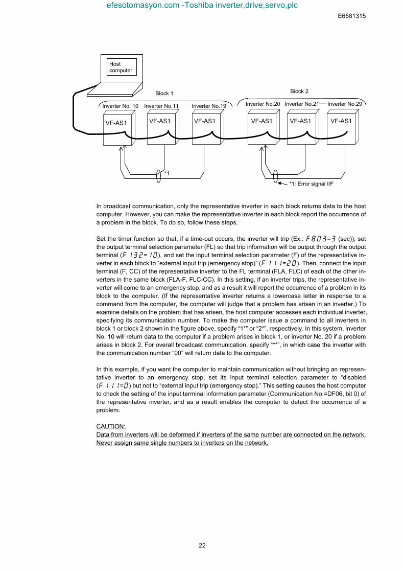
In broadcast communication, only the representative inverter in each block returns data to the hostcomputer. However, you can make the representative inverter in each block report the occurrence ofa problem in the block. To do so, follow these steps.
Set the timer function so that, if a time-out occurs, the inverter will trip (Ex.: = (sec)), setthe output terminal selection parameter (FL) so that trip information will be output through the outputterminal (=), and set the input terminal selection parameter (F) of the representative in-verter in each block to “external input trip (emergency stop)” (=). Then, connect the inputterminal (F, CC) of the representative inverter to the FL terminal (FLA, FLC) of each of the other in-verters in the same block (FLA-F, FLC-CC). In this setting, if an inverter trips, the representative in-verter will come to an emergency stop, and as a result it will report the occurrence of a problem in itsblock to the computer. (If the representative inverter returns a lowercase letter in response to acommand from the computer, the computer will judge that a problem has arisen in an inverter.) Toexamine details on the problem that has arisen, the host computer accesses each individual inverter,specifying its communication number. To make the computer issue a command to all inverters inblock 1 or block 2 shown in the figure above, specify “1*” or “2*”, respectively. In this system, inverterNo. 10 will return data to the computer if a problem arises in block 1, or inverter No. 20 if a problemarises in block 2. For overall broadcast communication, specify “**”, in which case the inverter withthe communication number “00” will return data to the computer.
In this example, if you want the computer to maintain communication without bringing an represen-tative inverter to an emergency stop, set its input terminal selection parameter to “disabled(=) but not to “external input trip (emergency stop).” This setting causes the host computerto check the setting of the input terminal information parameter (Communication No.=DF06, bit 0) ofthe representative inverter, and as a result enables the computer to detect the occurrence of aproblem.
CAUTION:Data from inverters will be deformed if inverters of the same number are connected on the network.Never assign same single numbers to inverters on the network.
Hostcomputer
Inverter No. 10 Inverter No.11 Inverter No.19 Inverter No.20 Inverter No.21 Inverter No.29
*1: Error signal I/F
*1
Block 2Block 1
VF-AS1 VF-AS1 VF-AS1 VF-AS1 VF-AS1 VF-AS1
efesotomasyon.com -Toshiba inverter,drive,servo,plc
E6581315
23
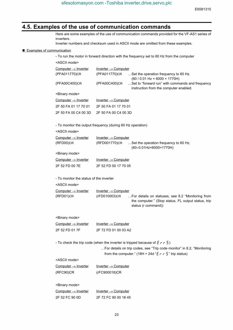
4.5. Examples of the use of communication commandsHere are some examples of the use of communication commands provided for the VF-AS1 series ofinverters.Inverter numbers and checksum used in ASCII mode are omitted from these examples.
Examples of communication- To run the motor in forward direction with the frequency set to 60 Hz from the computer
<ASCII mode>
Computer → Inverter Inverter → Computer(PFA011770)CR (PFA011770)CR …Set the operation frequency to 60 Hz.
(60 / 0.01 Hz = 6000 = 1770H)(PFA00C400)CR (PFA00C400)CR …Set to “forward run” with commands and frequency
instruction from the computer enabled.<Binary mode>
Computer → Inverter Inverter → Computer
2F 50 FA 01 17 70 01 2F 50 FA 01 17 70 01
2F 50 FA 00 C4 00 3D 2F 50 FA 00 C4 00 3D
- To monitor the output frequency (during 60 Hz operation)
<ASCII mode>
Computer → Inverter Inverter → Computer(RFD00)CR (RFD001770)CR …Set the operation frequency to 60 Hz.
(60÷0.01Hz=6000=1770H)<Binary mode>
Computer → Inverter Inverter → Computer
2F 52 FD 00 7E 2F 52 FD 00 17 70 05
- To monitor the status of the inverter
<ASCII mode>
Computer → Inverter Inverter → Computer(RFD01)CR (rFD010003)CR …For details on statuses, see 8.2 “Monitoring from
the computer.” (Stop status, FL output status, tripstatus (r command))
<Binary mode>
Computer → Inverter Inverter → Computer
2F 52 FD 01 7F 2F 72 FD 01 00 03 A2
- To check the trip code (when the inverter is tripped because of )…For details on trip codes, see “Trip code monitor” in 8.2, “Monitoring
from the computer.” (18H = 24d “” trip status)
<ASCII mode>
Computer → Inverter Inverter → Computer
(RFC90)CR (rFC900018)CR
<Binary mode>
Computer → Inverter Inverter → Computer
2F 52 FC 90 0D 2F 72 FC 90 00 18 45
efesotomasyon.com -Toshiba inverter,drive,servo,plc
E6581315
24
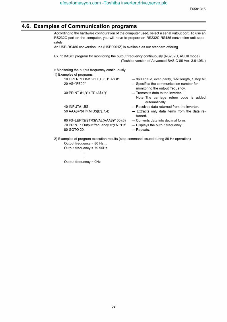
4.6. Examples of Communication programsAccording to the hardware configuration of the computer used, select a serial output port. To use anRS232C port on the computer, you will have to prepare an RS232C-RS485 conversion unit sepa-rately.An USB-RS485 conversion unit (USB0001Z) is available as our standard offering.
Ex. 1: BASIC program for monitoring the output frequency continuously (RS232C, ASCII mode)(Toshiba version of Advanced BASIC-86 Ver. 3.01.05J)
◊ Monitoring the output frequency continuously1) Examples of programs
10 OPEN "COM1:9600,E,8,1" AS #1 --- 9600 baud, even parity, 8-bit length, 1 stop bit20 A$=”FE00” --- Specifies the communication number for
monitoring the output frequency.30 PRINT #1,"("+”R”+A$+")" --- Transmits data to the inverter.
Note: The carriage return code is addedautomatically.
40 INPUT#1,B$ --- Receives data returned from the inverter.50 AAA$=“&H”+MID$(B$,7,4) --- Extracts only data items from the data re-
turned.60 F$=LEFT$(STR$(VAL(AAA$)/100),6) --- Converts data into decimal form.70 PRINT " Output frequency =";F$+“Hz” --- Displays the output frequency.80 GOTO 20 --- Repeats.
2) Examples of program execution results (stop command issued during 80 Hz operation)Output frequency = 80 Hz ...Output frequency = 79.95Hz : :Output frequency = 0Hz
efesotomasyon.com -Toshiba inverter,drive,servo,plc
E6581315
25
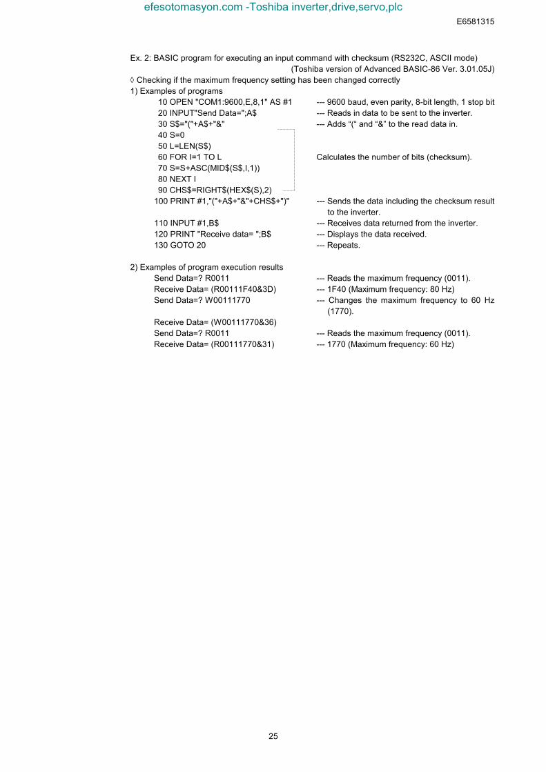
Ex. 2: BASIC program for executing an input command with checksum (RS232C, ASCII mode)(Toshiba version of Advanced BASIC-86 Ver. 3.01.05J)
◊ Checking if the maximum frequency setting has been changed correctly1) Examples of programs
10 OPEN "COM1:9600,E,8,1" AS #1 --- 9600 baud, even parity, 8-bit length, 1 stop bit 20 INPUT"Send Data=";A$ --- Reads in data to be sent to the inverter. 30 S$="("+A$+"&" --- Adds “(“ and “&” to the read data in. 40 S=0 50 L=LEN(S$) 60 FOR I=1 TO L Calculates the number of bits (checksum). 70 S=S+ASC(MID$(S$,I,1)) 80 NEXT I 90 CHS$=RIGHT$(HEX$(S),2)100 PRINT #1,"("+A$+"&"+CHS$+")" --- Sends the data including the checksum result
to the inverter.110 INPUT #1,B$ --- Receives data returned from the inverter.120 PRINT "Receive data= ";B$ --- Displays the data received.130 GOTO 20 --- Repeats.
2) Examples of program execution resultsSend Data=? R0011 --- Reads the maximum frequency (0011).Receive Data= (R00111F40&3D) --- 1F40 (Maximum frequency: 80 Hz)Send Data=? W00111770 --- Changes the maximum frequency to 60 Hz
(1770).Receive Data= (W00111770&36)Send Data=? R0011 --- Reads the maximum frequency (0011).Receive Data= (R00111770&31) --- 1770 (Maximum frequency: 60 Hz)
efesotomasyon.com -Toshiba inverter,drive,servo,plc
E6581315
26
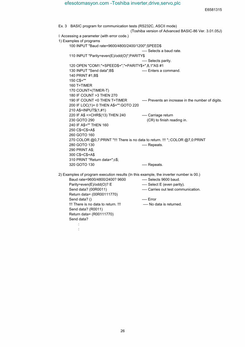
Ex. 3 BASIC program for communication tests (RS232C, ASCII mode)(Toshiba version of Advanced BASIC-86 Ver. 3.01.05J)
◊ Accessing a parameter (with error code.)1) Examples of programs
100 INPUT "Baud rate=9600/4800/2400/1200";SPEED$---- Selects a baud rate.
110 INPUT "Parity=even(E)/odd(O)";PARITY$---- Selects parity.
120 OPEN "COM1:"+SPEED$+","+PARITY$+",8,1"AS #1130 INPUT "Send data";B$ ---- Enters a command.140 PRINT #1,B$150 C$=""160 T=TIMER170 COUNT=(TIMER-T)180 IF COUNT >3 THEN 270190 IF COUNT <0 THEN T=TIMER ---- Prevents an increase in the number of digits.200 IF LOC(1)= 0 THEN A$="":GOTO 220210 A$=INPUT$(1,#1)220 IF A$ <>CHR$(13) THEN 240 ---- Carriage return230 GOTO 290 (CR) to finish reading in.240 IF A$="" THEN 160250 C$=C$+A$260 GOTO 160270 COLOR @0,7:PRINT "!!! There is no data to return. !!! ";:COLOR @7,0:PRINT280 GOTO 130 ---- Repeats.290 PRINT A$;300 C$=C$+A$310 PRINT "Return data=";c$;320 GOTO 130 ---- Repeats.
2) Examples of program execution results (In this example, the inverter number is 00.)Baud rate=9600/4800/2400? 9600 ---- Selects 9600 baud.Parity=even(E)/odd(O)? E ---- Select E (even parity).Send data? (00R0011) ---- Carries out test communication.Return data= (00R00111770)Send data? () ---- Error!!! There is no data to return. !!! ---- No data is returned.Send data? (R0011)Return data= (R00111770)Send data? : :
efesotomasyon.com -Toshiba inverter,drive,servo,plc
E6581315
27
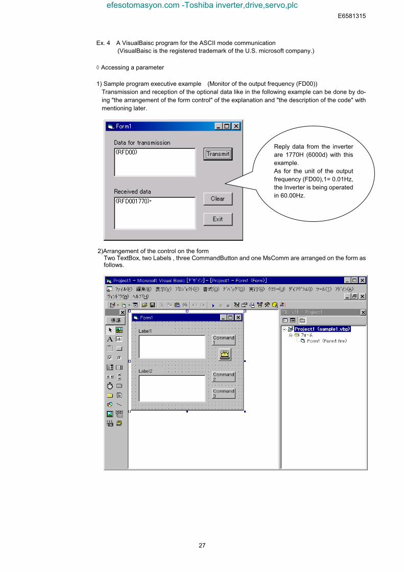
Ex. 4 A VisualBaisc program for the ASCII mode communication (VisualBaisc is the registered trademark of the U.S. microsoft company.)
◊ Accessing a parameter
1) Sample program executive example (Monitor of the output frequency (FD00))Transmission and reception of the optional data like in the following example can be done by do-ing "the arrangement of the form control" of the explanation and "the description of the code" withmentioning later.
2)Arrangement of the control on the formTwo TextBox, two Labels , three CommandButton and one MsComm are arranged on the form asfollows.
Reply data from the inverterare 1770H (6000d) with thisexample.As for the unit of the outputfrequency (FD00),1= 0.01Hz,the Inverter is being operatedin 60.00Hz.
efesotomasyon.com -Toshiba inverter,drive,servo,plc
E6581315
28
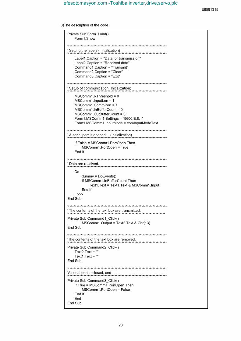
3)The description of the code
Private Sub Form_Load() Form1.Show '**********************************************************************' Setting the labels (Initialization)'********************************************************************** Label1.Caption = "Data for transmission" Label2.Caption = "Received data" Command1.Caption = "Transmit" Command2.Caption = "Clear" Command3.Caption = "Exit" '**********************************************************************' Setup of communication (Initialization)'********************************************************************** MSComm1.RThreshold = 0 MSComm1.InputLen = 1 MSComm1.CommPort = 1 MSComm1.InBufferCount = 0 MSComm1.OutBufferCount = 0 Form1.MSComm1.Settings = "9600,E,8,1" Form1.MSComm1.InputMode = comInputModeText
'**********************************************************************' A serial port is opened. (Initialization)'********************************************************************** If False = MSComm1.PortOpen Then MSComm1.PortOpen = True End If '**********************************************************************' Data are received.'********************************************************************** Do dummy = DoEvents() If MSComm1.InBufferCount Then Text1.Text = Text1.Text & MSComm1.Input End If LoopEnd Sub
'**********************************************************************' The contents of the text box are transmitted.'**********************************************************************Private Sub Command1_Click() MSComm1.Output = Text2.Text & Chr(13)End Sub
'**********************************************************************'The contents of the text box are removed.'**********************************************************************Private Sub Command2_Click() Text2.Text = "" Text1.Text = ""End Sub
'**********************************************************************'A serial port is closed, end'**********************************************************************Private Sub Command3_Click() If True = MSComm1.PortOpen Then MSComm1.PortOpen = False End If EndEnd Sub
efesotomasyon.com -Toshiba inverter,drive,servo,plc
E6581315
29
5. MODBUS-RTU protocolThe MODBUS-RTU protocol of VF-AS1 supports only part of the MODBUS-RTU protocol. Onlytwo commands are supported, “03: Multiple data read (limited only to two bytes)” and “06: Wordwrites.” All data will be binary codes.
Parameter Setting
• Protocol selection (, )Select “MODBUS-RTU (, = ) in the communication selection parameters.“TOSHIBA” (, =) is set for communication protocol selection in initial shipment set-ting. (See “3. Communication protocol.”)* Caution when selecting MODBUS-RTUNote that selecting this protocol disables the inter-drive communication functions set with parame-ters and , and the block communication functions set with parameters , and to .
• Inverter number ()Inverter numbers. 0 to 247 can be specified in MODBUS-RTU. “0” is allocated to broadcast com-munication (no return). Set between 1 and 247.
<Related Parameter: Change and set as necessary> : Baud rate (2-wire RS485) : Communication speed (4-wire RS485) : Parity (common to 2-wire RS485 and 4-wire RS485)
Data Exchange with Inverters
The inverters are always ready to receive messages and perform slave operation in response tocomputer requests.A transmission error will result if the transmission format does not match. The inverters will not re-spond if a framing error, parity error, CRC error or an inverter number mismatch occurs. If no re-sponse is received, the computer side recognizes that a communication error has occurred.Transmit data again.
(1) In case spacing for more than 3.5 bytes are provided before characters, all data immediatelypreceding it will be aborted. Data will sometimes be aborted if spacing for 1.5 bytes or more isprovided between characters. (See “3.1. About the handling of received frames.”)
(2) Communication will be effective only when inverter numbers match or the communication modeis 0 (Broadcast communication). If there is no inverter number that matches or 0 (broadcastcommunication) is specified, no response is returned by any inverter.
(3) Message reception will end if spacing for more than 3.5 bytes are provided at the end of charac-ters. (See “3.1. About the handling of received frames.”)
(4) If no communication take place within the time specified using the timer function, the computerwill assume that a communication error has occurred and trip the inverter. The timer function isdisabled when the inverter is turned on or initialized. For details, see Section 7.3, “Timer function,Communication time-out time action.”
(5) On executing the command received, the inverter returns data to the computer. For the responsetime, see Appendix 2, “Response time.”
Caution:Communication is not possible for about two seconds after the power is supplied to the inverter untilthe initial setting is completed. If the control power is shut down due to an instantaneous voltagedrop, communication is temporarily interrupted.
efesotomasyon.com -Toshiba inverter,drive,servo,plc
E6581315
30
5.1. MODBUS-RTU transmission formatMODBUS-RTU sends and receives binary data without a frame-synchronizing start code and de-fines the blank time to recognize the start of a frame. MODBUS-RTU decides the data that is firstreceived subsequently as the first byte of a frame after a blank time for 3.5 bytes at the on-goingcommunication speed.
5.1.1. Read command (03) Computer → Inverter *The text size is 8 bytes fixed.
InverterNo. Command
Commu-nication
No.(high)
Commu-nication
No.(low)
Numberof DataGroups(high)
Numberof DataGroups
(low)
CRC(low)
CRC(high)(3.5bytes
Blank)
03 00 01
(3.5bytesBlank)
1) Inverter No.. (1 byte) : Specify an inverter number between 0 and 247 (00H to F7H).Command processing will be executed only broadcast communication “0” and withthose inverters that match set inverter numbers. Data will not be returned if “0”(broadcast communication) and inverter numbers do not match.
2) Command (1 byte) : Set the read command (03H fixed).
3) Communication No.. (2 bytes) : Set in the order of high to low numbers.
4) Number of data groups (2 bytes) : Set the number of data words 0001 (fixed) in the order of high to low numbers.
5) CRC (2 bytes) : Set generation results of CRC in the order of low to high numbers.. For themethod to generate CRC, see “5.2 CRC Generation.” Note that the setting se-quence is reversal to that of others.
Inverter → Computer (Normal return) *The text size is 7 bytes fixed.
InverterNo.
CommandNumber of
DataRead data
(high)Read data
(low)CRC(low)
CRC(high)(3.5bytes
Blank)03 02
(3.5bytesBlank)
1) Command (1 byte) : Read command (03H fixed) will be returned.
2) Number of data : A number of data bytes (02H fixed) will be returned. The number of data groups fortransmission to the inverters is 2 bytes and 01H fixed. Note that the number of data re-turned by the inverters is 1 byte and 02H fixed.
3) Read data (2 bytes) : Returned in the order of read data (high) and (low).
Inverter → Computer (Abnormal return) *The text size is 5 bytes fixed.
Inverter No. Command Error CodeCRC(low)
CRC(high)(3.5bytes
Blank)83
(3.5bytesBlank)
1) Command (1 byte) : 83H fixed (Read command error) (Command + 80H)
2) Error code (1 byte) : See “4.3 Transmission errors.”
Example: Reading output frequency (During 60Hz operation) (Computer → inverter) 01 03 FD 00 00 01 B5 A6 (Inverter → computer) 01 03 02 17 70 B6 50
Example: Data specification error (Computer → inverter) 01 03 FD 00 00 02 F5 A7 (Inverter → computer) 01 83 03 01 31
efesotomasyon.com -Toshiba inverter,drive,servo,plc
E6581315
31
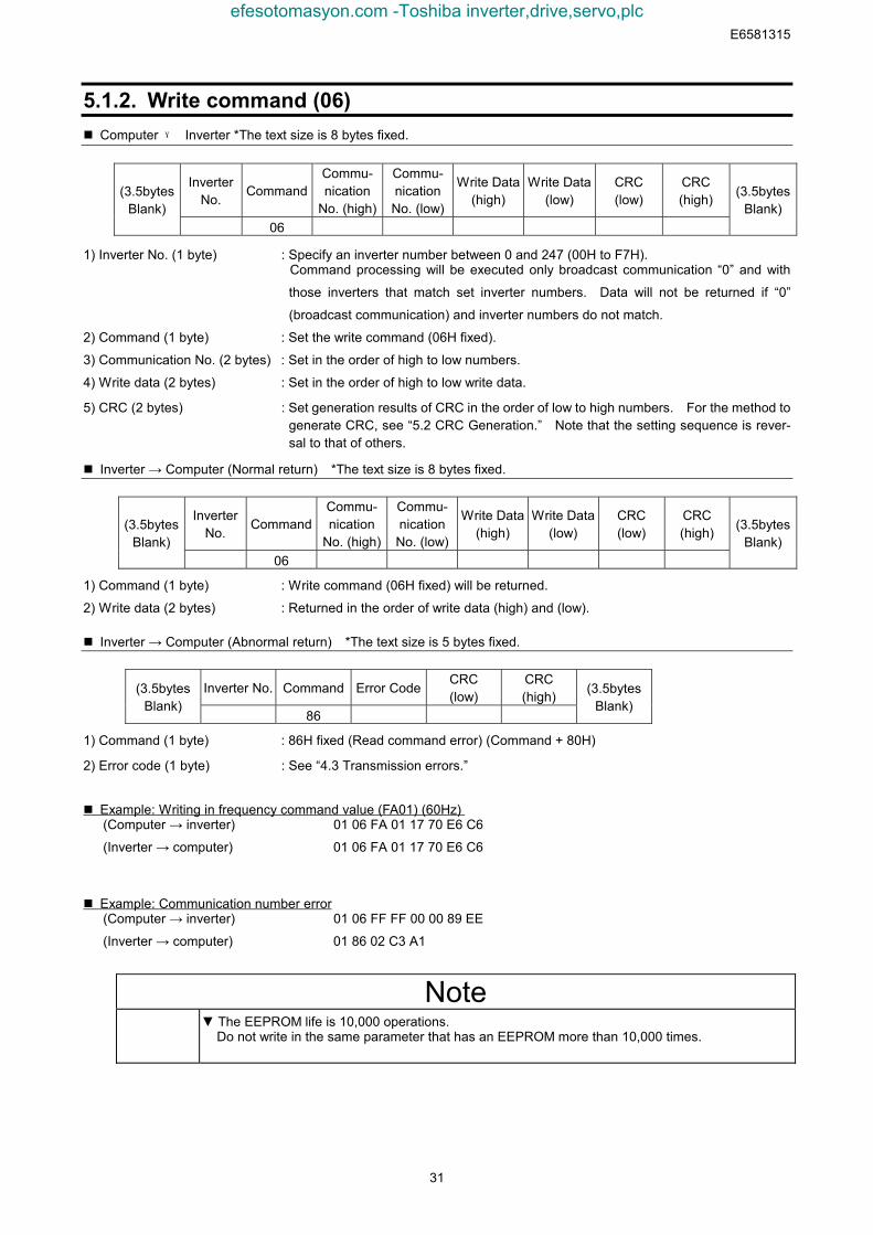
5.1.2. Write command (06) Computer → Inverter *The text size is 8 bytes fixed.
InverterNo.
CommandCommu-nication
No. (high)
Commu-nicationNo. (low)
Write Data(high)
Write Data(low)
CRC(low)
CRC(high)(3.5bytes
Blank)06
(3.5bytesBlank)
1) Inverter No. (1 byte) : Specify an inverter number between 0 and 247 (00H to F7H).Command processing will be executed only broadcast communication “0” and with
those inverters that match set inverter numbers. Data will not be returned if “0”
(broadcast communication) and inverter numbers do not match.
2) Command (1 byte) : Set the write command (06H fixed).
3) Communication No. (2 bytes) : Set in the order of high to low numbers.
4) Write data (2 bytes) : Set in the order of high to low write data.
5) CRC (2 bytes) : Set generation results of CRC in the order of low to high numbers. For the method togenerate CRC, see “5.2 CRC Generation.” Note that the setting sequence is rever-sal to that of others.
Inverter → Computer (Normal return) *The text size is 8 bytes fixed.
InverterNo.
CommandCommu-nication
No. (high)
Commu-nicationNo. (low)
Write Data(high)
Write Data(low)
CRC(low)
CRC(high)(3.5bytes
Blank)06
(3.5bytesBlank)
1) Command (1 byte) : Write command (06H fixed) will be returned.
2) Write data (2 bytes) : Returned in the order of write data (high) and (low).
Inverter → Computer (Abnormal return) *The text size is 5 bytes fixed.
Inverter No. Command Error CodeCRC(low)
CRC(high)(3.5bytes
Blank)86
(3.5bytesBlank)
1) Command (1 byte) : 86H fixed (Read command error) (Command + 80H)
2) Error code (1 byte) : See “4.3 Transmission errors.”
Example: Writing in frequency command value (FA01) (60Hz) (Computer → inverter) 01 06 FA 01 17 70 E6 C6
(Inverter → computer) 01 06 FA 01 17 70 E6 C6
Example: Communication number error (Computer → inverter) 01 06 FF FF 00 00 89 EE
(Inverter → computer) 01 86 02 C3 A1
Note▼ The EEPROM life is 10,000 operations.
Do not write in the same parameter that has an EEPROM more than 10,000 times.
efesotomasyon.com -Toshiba inverter,drive,servo,plc
E6581315
32
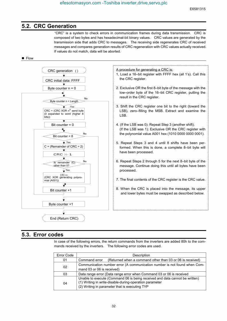
5.2. CRC Generation“CRC” is a system to check errors in communication frames during data transmission. CRC iscomposed of two bytes and has hexadecimal-bit binary values. CRC values are generated by thetransmission side that adds CRC to messages. The receiving side regenerates CRC of receivedmessages and compares generation results of CRC regeneration with CRC values actually received.If values do not match, data will be aborted.
Flow
5.3. Error codesIn case of the following errors, the return commands from the inverters are added 80h to the com-mands received by the inverters. The following error codes are used.
Error Code Description01 Command error (Returned when a command other than 03 or 06 is received)
02Communication number error (A communication number is not found when Com-mand 03 or 06 is received)
03 Data range error (Data range error when Command 03 or 06 is received
04Unable to execute (Command 06 is being received and data cannot be written)(1) Writing in write-disable-during-operation parameter(2) Writing in parameter that is executing TYP
A procedure for generating a CRC is:1, Load a 16–bit register with FFFF hex (all 1’s). Call this
the CRC register.
2. Exclusive OR the first 8–bit byte of the message with thelow–order byte of the 16–bit CRC register, putting theresult in the CRC register.
3. Shift the CRC register one bit to the right (toward theLSB), zero–filling the MSB. Extract and examine theLSB.
4. (If the LSB was 0): Repeat Step 3 (another shift).(If the LSB was 1): Exclusive OR the CRC register withthe polynomial value A001 hex (1010 0000 0000 0001).
5. Repeat Steps 3 and 4 until 8 shifts have been per-formed. When this is done, a complete 8–bit byte willhave been processed.
6. Repeat Steps 2 through 5 for the next 8–bit byte of themessage. Continue doing this until all bytes have beenprocessed.
7. The final contents of the CRC register is the CRC value.
8. When the CRC is placed into the message, its upperand lower bytes must be swapped as described below.
CRC generation ( )
End (Return CRC)
Byte counter n = 0
Byte counter n < Length
CRC = (CRC XOR nth send byte(0 expanded to word (higher 8bits))
No
Yes
Bit counter = 0
CRC initial data: FFFF
Bit counter < 8
C = (Remainder of CRC ÷ 2)
CRC >> 1
Is remainder (C)other than 0?
CRC=(CRC XOR generating polyno-mial (A001))
Bit counter +1
Byte counter +1
Yes
No
Yes
No
efesotomasyon.com -Toshiba inverter,drive,servo,plc
E6581315
33
<Notes>
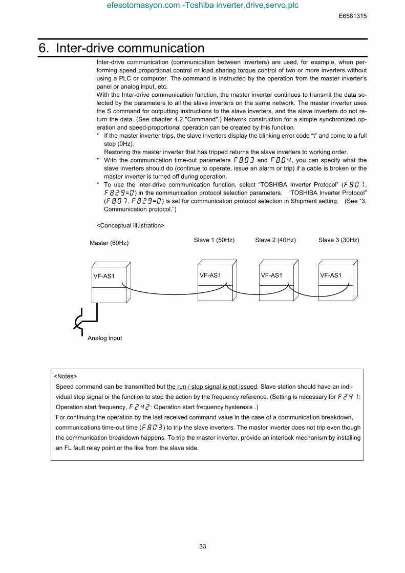
Speed command can be transmitted but the run / stop signal is not issued. Slave station should have an indi-
vidual stop signal or the function to stop the action by the frequency reference. (Setting is necessary for :
Operation start frequency, : Operation start frequency hysteresis .)
For continuing the operation by the last received command value in the case of a communication breakdown,
communications time-out time () to trip the slave inverters. The master inverter does not trip even though
the communication breakdown happens. To trip the master inverter, provide an interlock mechanism by installing
an FL fault relay point or the like from the slave side.
6. Inter-drive communicationInter-drive communication (communication between inverters) are used, for example, when per-forming speed proportional control or load sharing torque control of two or more inverters withoutusing a PLC or computer. The command is instructed by the operation from the master inverter’spanel or analog input, etc.With the Inter-drive communication function, the master inverter continues to transmit the data se-lected by the parameters to all the slave inverters on the same network. The master inverter usesthe S command for outputting instructions to the slave inverters, and the slave inverters do not re-turn the data. (See chapter 4.2 "Command".) Network construction for a simple synchronized op-eration and speed-proportional operation can be created by this function.* If the master inverter trips, the slave inverters display the blinking error code “t” and come to a full
stop (0Hz).Restoring the master inverter that has tripped returns the slave inverters to working order.
* With the communication time-out parameters f803 and f804, you can specify what theslave inverters should do (continue to operate, issue an alarm or trip) if a cable is broken or themaster inverter is turned off during operation.
* To use the inter-drive communication function, select “TOSHIBA Inverter Protocol” (,=) in the communication protocol selection parameters. “TOSHIBA Inverter Protocol”(, =) is set for communication protocol selection in Shipment setting. (See “3.Communication protocol.”)
<Conceptual illustration>
Master (60Hz) Slave 1 (50Hz) Slave 2 (40Hz) Slave 3 (30Hz)
VF-AS1 VF-AS1 VF-AS1 VF-AS1
Analog input
efesotomasyon.com -Toshiba inverter,drive,servo,plc

E6581315
34
Wiring (2-wire RS485 communication)
Master
RXD+/TXD+
RXD-/TXD-
SG
CN1
Pin-4
Pin-5
Pin-8(Pin-3)
Straight Straight
Terminating resistance120Ω-1/2W
Straight
Slave
RXD+/TXD+
RXD-/TXD-
SG
Slave
RXD+/TXD+
RXD-/TXD-
SG
Slave
RXD+/TXD+
RXD-/TXD-
SG
* Never use pin-7 (P11).
Wiring (4-wire RS485 communication))
* Never use pin-1 (Open) and pin-7 (P11).* You do not need to connect the master receive lines (pins 4 and 5) or the slave send lines (pins 3
and 6).
Terminating resistance120Ω-1/2W
Slave Slave SlaveCN1 Master
RXA
RXB
TXA
TXB
SG
RXA
RXB
TXA
TXB
SG
RXA
RXB
TXA
TXB
SG
RXA
RXB
TXA
TXB
SG
Cross Straight Straight
Pin-4
Pin-5
Pin-3
Pin-6
Pin-8(Pin-2)
efesotomasyon.com -Toshiba inverter,drive,servo,plc
E6581315
35
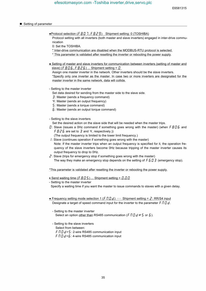
Setting of parameter
●Protocol selection (, ) Shipment setting: 0 (TOSHIBA)Protocol setting with all inverters (both master and slave inverters) engaged in inter-drive commu-nication0: Set the TOSHIBA.* Inter-drive communication are disabled when the MODBUS-RTU protocol is selected.* This parameter is validated after resetting the inverter or rebooting the power supply.
● Setting of master and slave inverters for communication between inverters (setting of master andslave) (, ) ... Shipment setting = Assign one master inverter in the network. Other inverters should be the slave inverters.*Specify only one inverter as the master. In case two or more inverters are designated for themaster inverter in the same network, data will collide.
- Setting to the master inverterSet data desired for sending from the master side to the slave side.: Master (sends a frequency command): Master (sends an output frequency): Master (sends a torque command): Master (sends an output torque command)
- Setting to the slave invertersSet the desired action on the slave side that will be needed when the master trips.
0: Slave (issues a 0Hz command if something goes wrong with the master) (when f806 andf826 are set to 3 and 4, respectively.))(The output frequency is limited to the lower limit frequency.)
1: Slave (continues operation if something goes wrong with the master) Note: If the master inverter trips when an output frequency is specified for it, the operation fre-quency of the slave inverters become 0Hz because tripping of the master inverter causes itsoutput frequency to drop to 0Hz.
2: Slave (trips for emergency stop if something goes wrong with the master)The way they make an emergency stop depends on the setting of f603 (emergency stop).
*This parameter is validated after resetting the inverter or rebooting the power supply.
• Send waiting time () ... Shipment setting = - Setting to the master inverter
Specify a waiting time if you want the master to issue commands to slaves with a given delay.
● Frequency setting mode selection 1 (fm0d) ・・・ Shipment setting = 2: RR/S4 inputDesignate a target of speed command input for the inverter to the parameter .
- Setting to the master inverterSelect an option other than RS485 communication (fm0d≠5 or 6).
- Setting to the slave invertersSelect from between:fm0d=5: 2-wire RS485 communication inputfm0d=6: 4-wire RS485 communication input
efesotomasyon.com -Toshiba inverter,drive,servo,plc
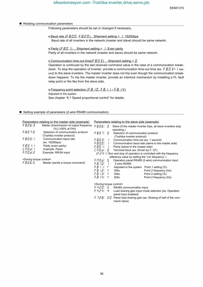
E6581315
36
Relating communication parametersFollowing parameters should be set or changed if necessary.
• Baud rate (, )... Shipment setting = : 19200bps Baud rate of all inverters in the network (master and slave) should be same network.
• Parity () ... Shipment setting = : Even parityParity of all inverters in the network (master and slave) should be same network.
• Communication time-out time() ... Shipment setting = Operation is continued by the last received command value in the case of a communication break-down. To stop the operation of inverter, provide a communication time-out time (ex. = sec-ond) to the slave inverters. The master inverter does not trip even though the communication break-down happens. To trip the master inverter, provide an interlock mechanism by installing a FL faultrelay point or the like from the slave side.
• Frequency point selection (, )Adjusted to the system.See chapter “6.1 Speed proportional control” for details.
Setting example of parameters (2-wire RS485 communication)
Parameters relating to the master side (example) Master (transmission of output frequency (%) (100% at FH)) Selection of communication protocol (Toshiba inverter protocol) Communication baud rate
(ex. 19200bps) Parity (even parity) Example: Panel Example: RR/S4 input
<During torque control> Master (sends a torque command)
Parameters relating to the slave side (example) Slave (If the master inverter trips, all slave inverters stop
operating.) Selection of communication protocol (Toshiba inverter protocol) Communication time-out (ex. 1 second) Communication baud rate (same to the master side) Parity (same to the master side) Terminal block (ex. Driven by F, ST)
( Run and stop of operation is controlled with the frequencyreference value by setting the “run frequency”.)
Operation panel RS485 (2-wire) communication input 2-wire RS485? Adjusted to the system Point 1 setting (%) ? Ditto Point 2 frequency (Hz) ? Ditto Point 2 setting (%) ? Ditto Point 2 frequency (Hz)
<During torque control> RS485 communication input Load sharing gain input mode selection (ex. Operation
panel input enabled) Panel load sharing gain (ex. Sharing of half of the com-
mand value)
efesotomasyon.com -Toshiba inverter,drive,servo,plc
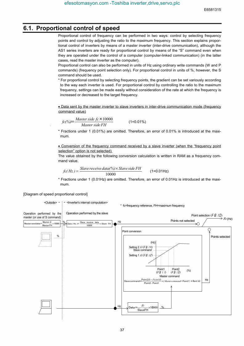
E6581315
37
6.1. Proportional control of speedProportional control of frequency can be performed in two ways: control by selecting frequencypoints and control by adjusting the ratio to the maximum frequency. This section explains propor-tional control of inverters by means of a master inverter (inter-drive communication), although theAS1 series inverters are ready for proportional control by means of the “S” command even whenthey are operated under the control of a computer (computer-linked communication) (in the lattercases, read the master inverter as the computer).Proportional control can also be performed in units of Hz using ordinary write commands (W and Pcommands) (frequency point selection only). For proportional control in units of %, however, the Scommand should be used.* For proportional control by selecting frequency points, the gradient can be set variously accordingto the way each inverter is used. For proportional control by controlling the ratio to the maximumfrequency, settings can be made easily without consideration of the rate at which the frequency isincreased or decreased to the target frequency.
• Data sent by the master inverter to slave inverters in inter-drive communication mode (frequencycommand value)
FHsideMaster
fcsideMaster(%)fc 10000×= (1=0.01%)
* Fractions under 1 (0.01%) are omitted. Therefore, an error of 0.01% is introduced at the maxi-mum.
• Conversion of the frequency command received by a slave inverter (when the “frequency pointselection” option is not selected)The value obtained by the following conversion calculation is written in RAM as a frequency com-mand value.
10000FHsideSlave(%)datareceiveSlave)Hz(fc ×= (1=0.01Hz)
* Fractions under 1 (0.01Hz) are omitted. Therefore, an error of 0.01Hz is introduced at the maxi-mum.
[Diagram of speed proportional control]
Point conversion
fcfcfc
1 oint-Point1)+PPoint1Point2
2 Pointcommand= Slave commandMaster(intPo ×
−− 1
FH Slave10000
data receive Slave=HzData ×)(01000
FHMaster
Master data= sendMaster ×fc
00010FH Slave
Data= ×fc
Setting 2 fc ()Slave command
Point2()
Point1()
Master command
Setting 1 fc ()
(Hz)
Hz
(%)
%
Operation performed by themaster (or use of S command)
<Outside> ← →<Inverter's internal computation>
Operation performed by the slave
%
%
Hz
Point selection ()Fc (Hz)Points not selected
Points selected
* fc=frequency reference, FH=maximum frequency
Hz
efesotomasyon.com -Toshiba inverter,drive,servo,plc
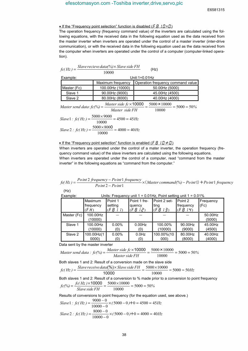
E6581315
38
• If the “Frequency point selection” function is disabled (=)The operation frequency (frequency command value) of the inverters are calculated using the fol-lowing equations, with the received data in the following equation used as the data received fromthe master inverter when inverters are operated under the control of a master inverter (inter-drivecommunication), or with the received data in the following equation used as the data received fromthe computer when inverters are operated under the control of a computer (computer-linked opera-tion).
10000FHsideSlave(%)datarecieveSlave)Hz(fc ×= (Hz)
Example: Unit:1=0.01HzMaximum frequency Operation frequency command value
Master (Fc) 100.00Hz (10000) 50.00Hz (5000) Slave 1 90.00Hz (9000) 45.00Hz (4500) Slave 2 80.00Hz (8000) 40.00Hz (4000)
%FHsideMaster
fcsideMaster(%)fcdatasendMaster 50500010000100005000 ===×= ×
:10000
Hz)Hz(fc:Slave 45450010000
900050001 ==×=
Hz)Hz(fc:Slave 40400010000
80050002 ==×= 0
• If the “Frequency point selection” function is enabled (≠)When inverters are operated under the control of a mater inverter, the operation frequency (fre-quency command value) of the slave inverters are calculated using the following equations.When inverters are operated under the control of a computer, read “command from the masterinverter” in the following equations as “command from the computer.”
frequencyintPointPo(%)commandMasterintPointPo
frequencyintPofrequencyintPo)Hz(fc 111212
)+( −×−−=
(Hz) Example: Units: Frequency unit 1 = 0.01Hz, Point setting unit 1 = 0.01%
Maximumfrequency()
Point 1setting()
Point 1 fre-quency()
Point 2 set-ting()
Point 2frequency()
Frequency(Fc)
Master (Fc) 100.00Hz(10000)
- - - - 50.00Hz(5000)
Slave 1 100.00Hz(10000)
0.00%(0)
0.00Hz(0)
100.00%(10000)
90.00Hz(9000)
45.00Hz(4500)
Slave 2 100.00Hz(10000)
0.00%(0)
0.0Hz(0)
100.00%(10000)
80.00Hz(8000)
40.00Hz(4000)
Data sent by the master inverter
%FHsideMaster
fcsideMaster(%)fc:datasendMaster 50500010000100005000 ===×= ×10000
Both slaves 1 and 2: Result of a conversion made on the slave side
HzFHsideSlavedatareceiveSlave)Hz(fc 50500010000100005000 ==×=×=
10000(%)
Both slaves 1 and 2: Result of a conversion to % made prior to a conversion to point frequency
%FHsideSlave
)Hz(fc(%)fc 50500010000100005000 ==×=×= 10000
Results of conversions to point frequency (for the equation used, see above.)
Hz)()Hz(fc:Slave 454500005000010000090001 ==−×
−−= +
Hz)()Hz(fc:Slave 404000005000010000080002 ==−×
−−= +
efesotomasyon.com -Toshiba inverter,drive,servo,plc
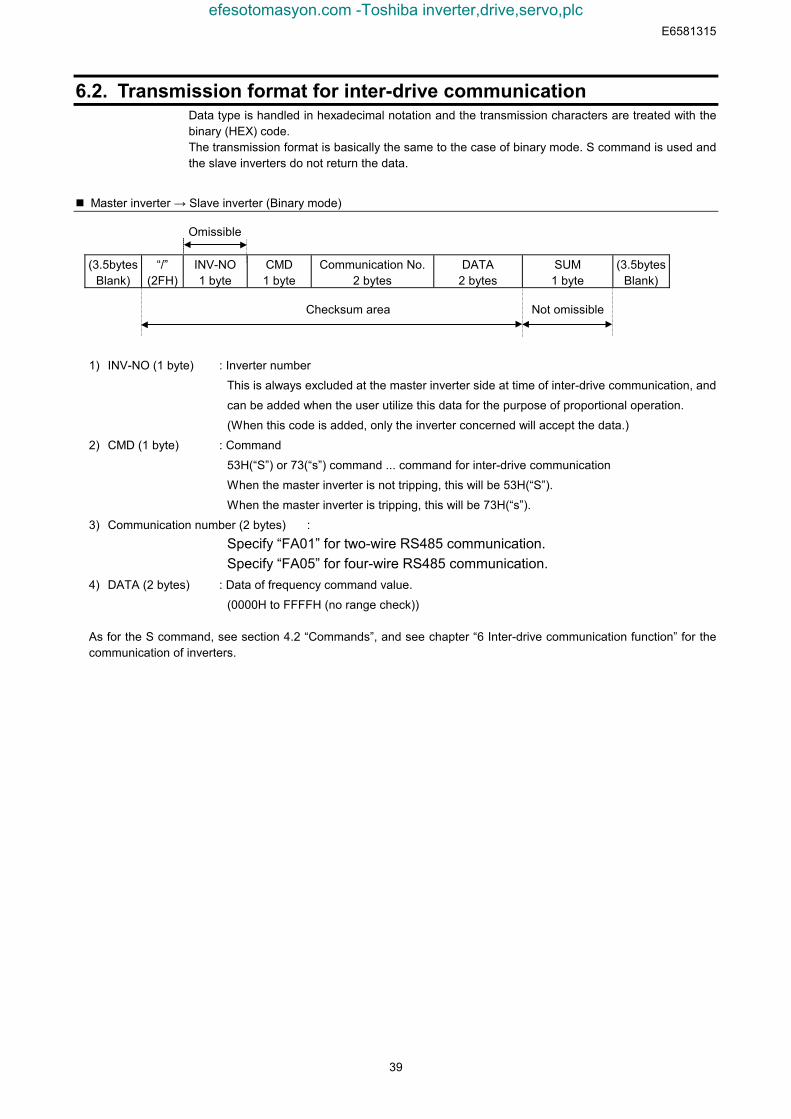
E6581315
39
6.2. Transmission format for inter-drive communicationData type is handled in hexadecimal notation and the transmission characters are treated with thebinary (HEX) code.The transmission format is basically the same to the case of binary mode. S command is used andthe slave inverters do not return the data.
Master inverter → Slave inverter (Binary mode)
Omissible
(3.5bytesBlank)
“/”(2FH)
INV-NO1 byte
CMD1 byte
Communication No.2 bytes
DATA2 bytes
SUM1 byte
(3.5bytesBlank)
Checksum area Not omissible
1) INV-NO (1 byte) : Inverter number
This is always excluded at the master inverter side at time of inter-drive communication, and
can be added when the user utilize this data for the purpose of proportional operation.
(When this code is added, only the inverter concerned will accept the data.)
2) CMD (1 byte) : Command
53H(“S”) or 73(“s”) command ... command for inter-drive communication
When the master inverter is not tripping, this will be 53H(“S”).
When the master inverter is tripping, this will be 73H(“s”).
3) Communication number (2 bytes) :Specify “FA01” for two-wire RS485 communication.Specify “FA05” for four-wire RS485 communication.
4) DATA (2 bytes) : Data of frequency command value.
(0000H to FFFFH (no range check))
As for the S command, see section 4.2 “Commands”, and see chapter “6 Inter-drive communication function” for thecommunication of inverters.
efesotomasyon.com -Toshiba inverter,drive,servo,plc
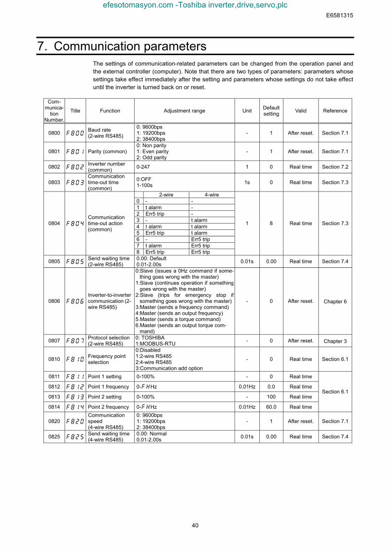
E6581315
40
7. Communication parametersThe settings of communication-related parameters can be changed from the operation panel andthe external controller (computer). Note that there are two types of parameters: parameters whosesettings take effect immediately after the setting and parameters whose settings do not take effectuntil the inverter is turned back on or reset.
Com-munica-
tionNumber.
Title Function Adjustment range Unit Defaultsetting Valid Reference
0800 Baud rate(2-wire RS485)
0: 9600bps1: 19200bps2: 38400bps
- 1 After reset. Section 7.1
0801 Parity (common)0: Non parity1: Even parity2: Odd parity
- 1 After reset. Section 7.1
0802 Inverter number(common) 0-247 1 0 Real time Section 7.2
0803 Communicationtime-out time(common)
0:OFF1-100s 1s 0 Real time Section 7.3
2-wire 4-wire0 - -1 t alarm -2 Err5 trip -3 - t alarm4 t alarm t alarm5 Err5 trip t alarm6 - Err5 trip7 t alarm Err5 trip
0804 Communicationtime-out action(common)
8 Err5 trip Err5 trip
1 8 Real time Section 7.3
0805 Send waiting time(2-wire RS485)
0.00: Default0.01-2.00s 0.01s 0.00 Real time Section 7.4
0806 Inverter-to-invertercommunication (2-wire RS485)
0:Slave (issues a 0Hz command if some-thing goes wrong with the master)
1:Slave (continues operation if somethinggoes wrong with the master)
2:Slave (trips for emergency stop ifsomething goes wrong with the master)
3:Master (sends a frequency command)4:Master (sends an output frequency)5.Master (sends a torque command)6.Master (sends an output torque com-
mand)
- 0 After reset. Chapter 6
0807 Protocol selection(2-wire RS485)
0: TOSHIBA1:MODBUS-RTU - 0 After reset. Chapter 3
0810 Frequency pointselection
0:Disabled1:2-wire RS4852:4-wire RS4853:Communication add option
- 0 Real time Section 6.1
0811 Point 1 setting 0-100% - 0 Real time
0812 Point 1 frequency 0-Hz 0.01Hz 0.0 Real time
0813 Point 2 setting 0-100% - 100 Real time
0814 Point 2 frequency 0-Hz 0.01Hz 60.0 Real time
Section 6.1
0820 Communicationspeed(4-wire RS485)
0: 9600bps1: 19200bps2: 38400bps
- 1 After reset. Section 7.1
0825 Send waiting time(4-wire RS485)
0.00: Normal0.01-2.00s 0.01s 0.00 Real time Section 7.4
efesotomasyon.com -Toshiba inverter,drive,servo,plc
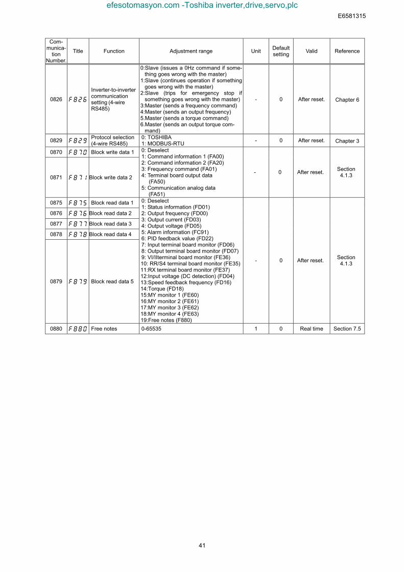
E6581315
41
Com-munica-
tionNumber.
Title Function Adjustment range Unit Defaultsetting Valid Reference
0826
Inverter-to-invertercommunicationsetting (4-wireRS485)
0:Slave (issues a 0Hz command if some-thing goes wrong with the master)
1:Slave (continues operation if somethinggoes wrong with the master)
2:Slave (trips for emergency stop ifsomething goes wrong with the master)
3:Master (sends a frequency command)4:Master (sends an output frequency)5.Master (sends a torque command)6.Master (sends an output torque com-
mand)
- 0 After reset. Chapter 6
0829 Protocol selection(4-wire RS485)
0: TOSHIBA1: MODBUS-RTU - 0 After reset. Chapter 3
0870 Block write data 1
0871 Block write data 2
0: Deselect1: Command information 1 (FA00)2: Command information 2 (FA20)3: Frequency command (FA01)4: Terminal board output data
(FA50)5: Communication analog data
(FA51)
- 0 After reset. Section4.1.3
0875 Block read data 1
0876 Block read data 2
0877 Block read data 3
0878 Block read data 4
0879 Block read data 5
0: Deselect1: Status information (FD01)2: Output frequency (FD00)3: Output current (FD03)4: Output voltage (FD05)5: Alarm information (FC91)6: PID feedback value (FD22)7: Input terminal board monitor (FD06)8: Output terminal board monitor (FD07)9: VI/IIterminal board monitor (FE36)10: RR/S4 terminal board monitor (FE35)11:RX terminal board monitor (FE37)12:Input voltage (DC detection) (FD04)13:Speed feedback frequency (FD16)14:Torque (FD18)15:MY monitor 1 (FE60)16:MY monitor 2 (FE61)17:MY monitor 3 (FE62)18:MY monitor 4 (FE63)19:Free notes (F880)
- 0 After reset. Section4.1.3
0880 Free notes 0-65535 1 0 Real time Section 7.5
efesotomasyon.com -Toshiba inverter,drive,servo,plc
E6581315
42
7.1. Baud rate(, ) , Parity ()
•Communication baud rate and parity bit should be uniform inside the same network.•This parameter is validated by resetting the power supply.
7.2. Inverter number()This parameter sets individual numbers with the inverters.Inverter numbers should not be duplicate inside the same network.Receiving data will be canceled if inverter numbers specified in individual communication and set bya parameter do not match.This parameter is validated from the communication after change
Data range: 0 to 247 (Initial value: 0)Parameters can be selected between 0 and 247. Note that the communication protocols limit in-verter numbers as follows:● TOSHIBA Inverter Protocol ASCII mode: 0 to 99● TOSHIBA Inverter Protocol Binary mode: 0 to 63● MODBUS Protocol: 0 to 247 (0: Broadcast communication)
efesotomasyon.com -Toshiba inverter,drive,servo,plc
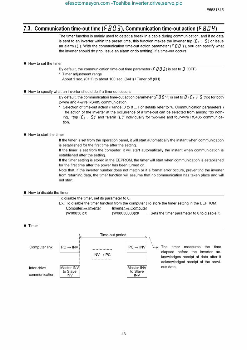
E6581315
43
7.3. Communication time-out time (), Communication time-out action (f804)The timer function is mainly used to detect a break in a cable during communication, and if no datais sent to an inverter within the preset time, this function makes the inverter trip () or issuean alarm (). With the communication time-out action parameter (), you can specify whatthe inverter should do (trip, issue an alarm or do nothing) if a time-out occurs.
How to set the timerBy default, the communication time-out time parameter () is set to (OFF).* Timer adjustment range
About 1 sec. (01H) to about 100 sec. (64H) / Timer off (0H)
How to specify what an inverter should do if a time-out occursBy default, the communication time-out action parameter () is set to ( trip) for both2-wire and 4-wire RS485 communication.* Selection of time-out action (Range: 0 to 8 ... For details refer to “6. Communication parameters.)
The action of the inverter at the occurrence of a time-out can be selected from among “do noth-ing,” “trip ()” and “alarm ()” individually for two-wire and four-wire RS485 communica-tion.
How to start the timerIf the timer is set from the operation panel, it will start automatically the instant when communicationis established for the first time after the setting.If the timer is set from the computer, it will start automatically the instant when communication isestablished after the setting.If the timer setting is stored in the EEPROM, the timer will start when communication is establishedfor the first time after the power has been turned on.Note that, if the inverter number does not match or if a format error occurs, preventing the inverterfrom returning data, the timer function will assume that no communication has taken place and willnot start.
How to disable the timerTo disable the timer, set its parameter to 0.Ex.: To disable the timer function from the computer (To store the timer setting in the EEPROM)
Computer → Inverter Inverter → Computer(W08030)CR (W08030000)CR ... Sets the timer parameter to 0 to disable it.
Timer
The timer measures the timeelapsed before the inverter ac-knowledges receipt of data after itacknowledged receipt of the previ-ous data.
Time-out period
PC → INVPC → INV
INV → PC
Computer link
Master INVto Slave
INV
Inter-drive
communication
Master INVto Slave
INV
efesotomasyon.com -Toshiba inverter,drive,servo,plc
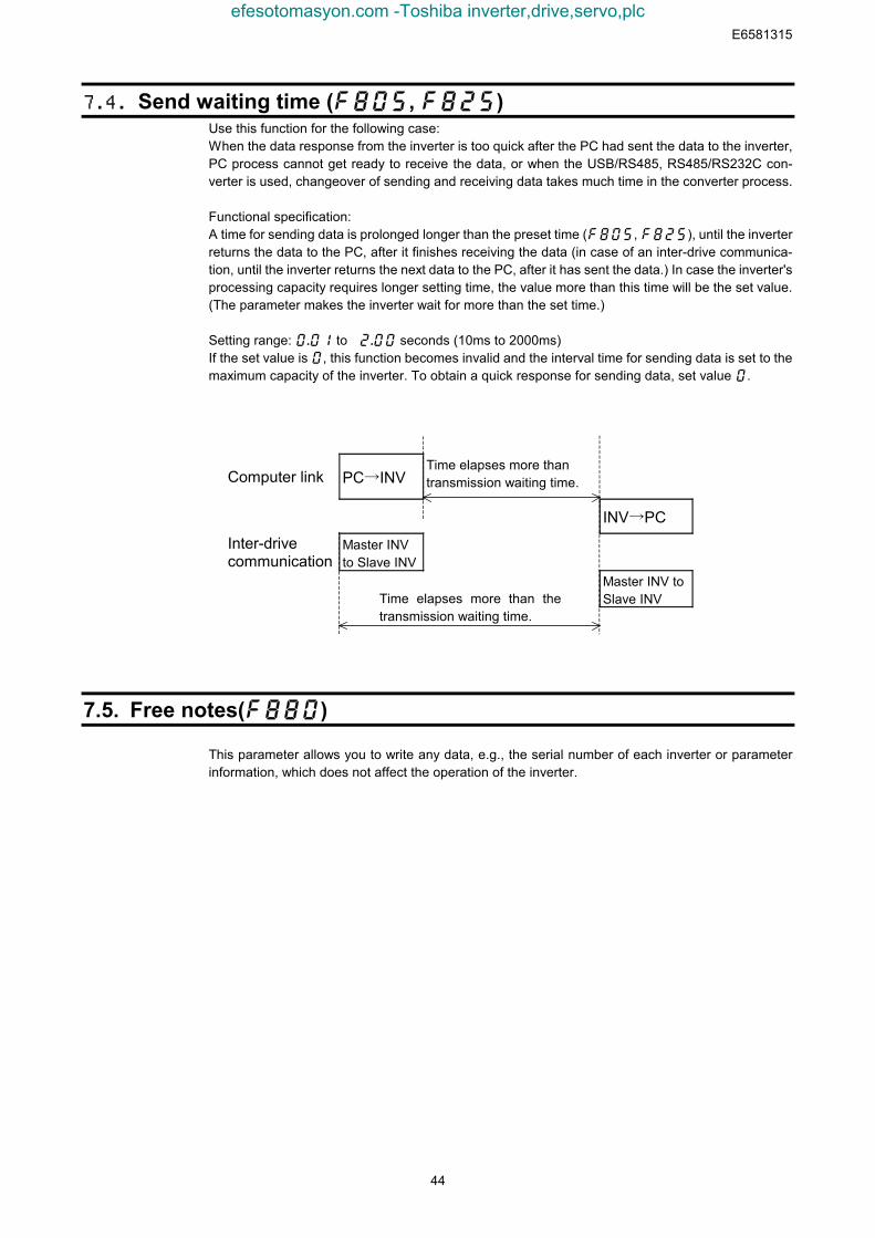
E6581315
44
7.4. Send waiting time (, )Use this function for the following case:When the data response from the inverter is too quick after the PC had sent the data to the inverter,PC process cannot get ready to receive the data, or when the USB/RS485, RS485/RS232C con-verter is used, changeover of sending and receiving data takes much time in the converter process.
Functional specification:A time for sending data is prolonged longer than the preset time (, ), until the inverterreturns the data to the PC, after it finishes receiving the data (in case of an inter-drive communica-tion, until the inverter returns the next data to the PC, after it has sent the data.) In case the inverter'sprocessing capacity requires longer setting time, the value more than this time will be the set value.(The parameter makes the inverter wait for more than the set time.)
Setting range: to seconds (10ms to 2000ms)If the set value is , this function becomes invalid and the interval time for sending data is set to themaximum capacity of the inverter. To obtain a quick response for sending data, set value .
Computer link PC→INVTime elapses more thantransmission waiting time.
INV→PC
Inter-drivecommunication
Master INVto Slave INV
Master INV toSlave INVTime elapses more than the
transmission waiting time.
7.5. Free notes()
This parameter allows you to write any data, e.g., the serial number of each inverter or parameterinformation, which does not affect the operation of the inverter.
efesotomasyon.com -Toshiba inverter,drive,servo,plc
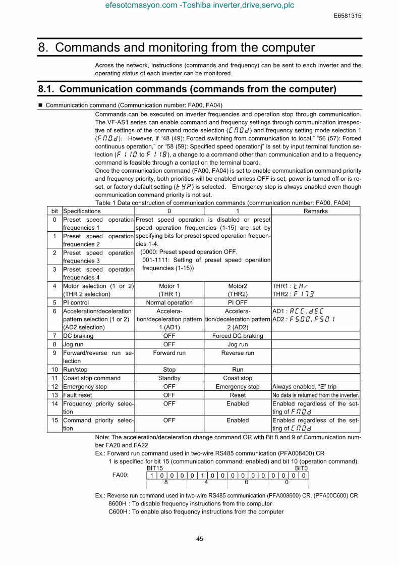
E6581315
45
8. Commands and monitoring from the computerAcross the network, instructions (commands and frequency) can be sent to each inverter and theoperating status of each inverter can be monitored.
8.1. Communication commands (commands from the computer) Communication command (Communication number: FA00, FA04)
Commands can be executed on inverter frequencies and operation stop through communication.The VF-AS1 series can enable command and frequency settings through communication irrespec-tive of settings of the command mode selection () and frequency setting mode selection 1(). However, if “48 (49): Forced switching from communication to local,” “56 (57): Forcedcontinuous operation,” or “58 (59): Specified speed operationj” is set by input terminal function se-lection ( to ), a change to a command other than communication and to a frequencycommand is feasible through a contact on the terminal board.Once the communication command (FA00, FA04) is set to enable communication command priorityand frequency priority, both priorities will be enabled unless OFF is set, power is turned off or is re-set, or factory default setting () is selected. Emergency stop is always enabled even thoughcommunication command priority is not set.Table 1 Data construction of communication commands (communication number: FA00, FA04)
bit Specifications 0 1 Remarks0 Preset speed operation
frequencies 11 Preset speed operation
frequencies 22 Preset speed operation
frequencies 33 Preset speed operation
frequencies 4
Preset speed operation is disabled or presetspeed operation frequencies (1-15) are set byspecifying bits for preset speed operation frequen-cies 1-4.
(0000: Preset speed operation OFF,001-1111: Setting of preset speed operationfrequencies (1-15))
4 Motor selection (1 or 2)(THR 2 selection)
Motor 1(THR 1)
Motor2(THR2)
THR1 : THR2 :
5 PI control Normal operation PI OFF6 Acceleration/deceleration
pattern selection (1 or 2)(AD2 selection)
Accelera-tion/deceleration pattern
1 (AD1)
Accelera-tion/deceleration pattern
2 (AD2)
AD1 : , AD2 : ,
7 DC braking OFF Forced DC braking8 Jog run OFF Jog run9 Forward/reverse run se-
lectionForward run Reverse run
10 Run/stop Stop Run11 Coast stop command Standby Coast stop12 Emergency stop OFF Emergency stop Always enabled, “E” trip13 Fault reset OFF Reset No data is returned from the inverter.14 Frequency priority selec-
tionOFF Enabled Enabled regardless of the set-
ting of 15 Command priority selec-
tionOFF Enabled Enabled regardless of the set-
ting of Note: The acceleration/deceleration change command OR with Bit 8 and 9 of Communication num-ber FA20 and FA22.Ex.: Forward run command used in two-wire RS485 communication (PFA008400) CR
1 is specified for bit 15 (communication command: enabled) and bit 10 (operation command).BIT15 BIT0
1 0 0 0 0 1 0 0 0 0 0 0 0 0 0 0
Ex.: Reverse run command used in two-wire RS485 communication (PFA008600) CR, (PFA00C600) CR8600H : To disable frequency instructions from the computerC600H : To enable also frequency instructions from the computer
FA00:0048
efesotomasyon.com -Toshiba inverter,drive,servo,plc
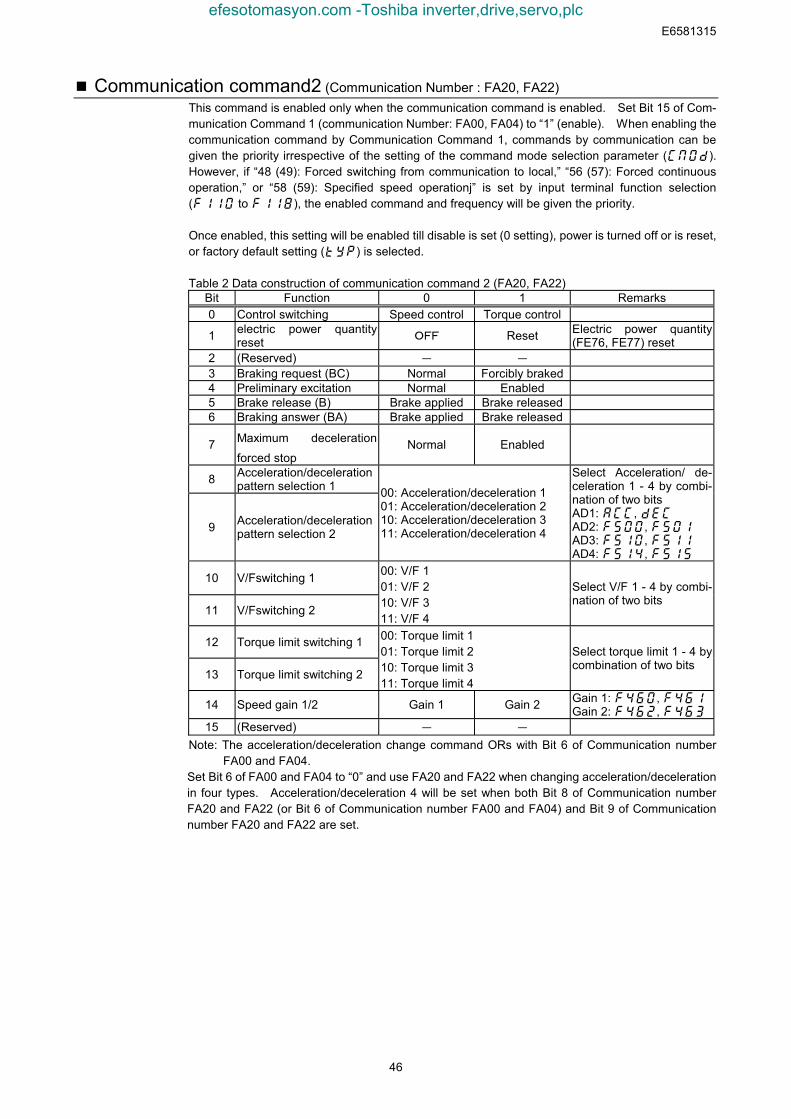
E6581315
46
Communication command2 (Communication Number : FA20, FA22)This command is enabled only when the communication command is enabled. Set Bit 15 of Com-munication Command 1 (communication Number: FA00, FA04) to “1” (enable). When enabling thecommunication command by Communication Command 1, commands by communication can begiven the priority irrespective of the setting of the command mode selection parameter ().However, if “48 (49): Forced switching from communication to local,” “56 (57): Forced continuousoperation,” or “58 (59): Specified speed operationj” is set by input terminal function selection( to ), the enabled command and frequency will be given the priority.
Once enabled, this setting will be enabled till disable is set (0 setting), power is turned off or is reset,or factory default setting () is selected.
Table 2 Data construction of communication command 2 (FA20, FA22)Bit Function 0 1 Remarks0 Control switching Speed control Torque control
1 electric power quantityreset OFF Reset Electric power quantity
(FE76, FE77) reset2 (Reserved) - -
3 Braking request (BC) Normal Forcibly braked4 Preliminary excitation Normal Enabled5 Brake release (B) Brake applied Brake released6 Braking answer (BA) Brake applied Brake released
7 Maximum deceleration
forced stopNormal Enabled
8 Acceleration/decelerationpattern selection 1
9 Acceleration/decelerationpattern selection 2
00: Acceleration/deceleration 101: Acceleration/deceleration 210: Acceleration/deceleration 311: Acceleration/deceleration 4
Select Acceleration/ de-celeration 1 - 4 by combi-nation of two bitsAD1: , AD2: , AD3: , AD4: ,
10 V/Fswitching 1
11 V/Fswitching 2
00: V/F 101: V/F 210: V/F 311: V/F 4
Select V/F 1 - 4 by combi-nation of two bits
12 Torque limit switching 1
13 Torque limit switching 2
00: Torque limit 101: Torque limit 210: Torque limit 311: Torque limit 4
Select torque limit 1 - 4 bycombination of two bits
14 Speed gain 1/2 Gain 1 Gain 2 Gain 1: , Gain 2: ,
15 (Reserved) - -
Note: The acceleration/deceleration change command ORs with Bit 6 of Communication numberFA00 and FA04.
Set Bit 6 of FA00 and FA04 to “0” and use FA20 and FA22 when changing acceleration/decelerationin four types. Acceleration/deceleration 4 will be set when both Bit 8 of Communication numberFA20 and FA22 (or Bit 6 of Communication number FA00 and FA04) and Bit 9 of Communicationnumber FA20 and FA22 are set.
efesotomasyon.com -Toshiba inverter,drive,servo,plc
E6581315
47
Frequency setting from the computer “Communication Number: FA01, FA05”Setting range: 0 to maximum frequency (fh)This frequency command is enabled only when the frequency command by communication is en-abled. To make frequency commands from the computer valid, set the frequency setting mode se-lection parameter (fmod) to RS485 communication (communication No. 0004: 5 (2-wire RS485communication input) or 6 (4-wire RS485 communication input) or select the “Command priority”option (bit 14 of FA00 and FA04: 1 (enabled)). In this case, frequency commands by communica-tion will be enabled independent of fmod setting.However, enabled commands and frequencies are given the priority if “48 (49): Forced switchingfrom communication to local,” “56 (57): Forced continuous operation,” or “58 (59): Specified speedoperation” is set by input terminal function selection (f11o to f118).Once enabled, this frequency setting will be enabled till disable is set (0 setting), power is turned offor is reset, or factory default setting (typ) is selected.
Set a frequency by communication hexadecimal in Communication Number FA01, FA05.(1=0.01Hz (unit))
Example: Operation frequency 80Hz command by 2-wire RS485 communication (PFA011F40) CR
80Hz=80÷0.01=8000=1F40H
Torque command setting from the computer “2-wire RS485 communication: FA30,4-wire RS485 communication: FA32
This section explains how to set a torque command value for inverters. The torque command valueset here takes effect if torque commands from the computer are valid when the inverters are in tor-que control mode (in cases where torque control is selected with the terminal board or with a com-munication command when ( is set to 4 or 8).To make torque commands from the computer valid, set the torque command selection parameter (communication No. 0420) to 5 (2-wire RS485 communication input) or 6 (4-wire RS485communication input). Once torque commands from the computer have been set, they remain validuntil they are changed, the inverters is turned off or reset, or the parameter for returning set-tings to their defaults is selected. (The settings of FA30 and FA32 are not stored in EEPROM.Therefore, they are cleared when the inverter is turned off or reset.)
When setting a torque for torque commands from the computer, specify a torque in hexadecimal(unit: 1=0.01%, two-wire RS485 communication: FA30 or four-wire RS485 communication: FA32).
Example: 50% torque command (PFA321388)50%=50÷0.01=5000=1388H
efesotomasyon.com -Toshiba inverter,drive,servo,plc
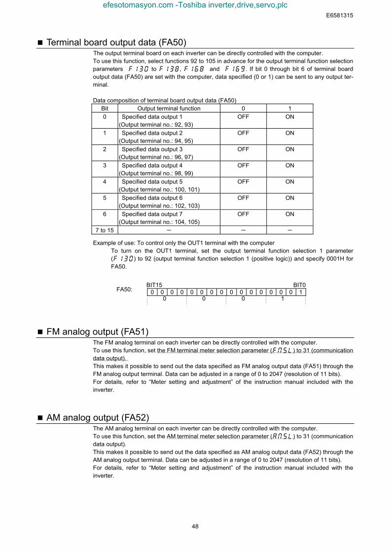
E6581315
48
Terminal board output data (FA50)The output terminal board on each inverter can be directly controlled with the computer.To use this function, select functions 92 to 105 in advance for the output terminal function selectionparameters f130 to f138, f168andf169. If bit 0 through bit 6 of terminal boardoutput data (FA50) are set with the computer, data specified (0 or 1) can be sent to any output ter-minal.
Data composition of terminal board output data (FA50)Bit Output terminal function 0 10 Specified data output 1
(Output terminal no.: 92, 93)OFF ON
1 Specified data output 2(Output terminal no.: 94, 95)
OFF ON
2 Specified data output 3(Output terminal no.: 96, 97)
OFF ON
3 Specified data output 4(Output terminal no.: 98, 99)
OFF ON
4 Specified data output 5(Output terminal no.: 100, 101)
OFF ON
5 Specified data output 6(Output terminal no.: 102, 103)
OFF ON
6 Specified data output 7(Output terminal no.: 104, 105)
OFF ON
7 to 15 - - -
Example of use: To control only the OUT1 terminal with the computerTo turn on the OUT1 terminal, set the output terminal function selection 1 parameter(f130) to 92 (output terminal function selection 1 (positive logic)) and specify 0001H forFA50.
BIT15 BIT00 0 0 0 0 0 0 0 0 0 0 0 0 0 0 1
FM analog output (FA51)The FM analog terminal on each inverter can be directly controlled with the computer.To use this function, set the FM terminal meter selection parameter (fmsl) to 31 (communicationdata output).This makes it possible to send out the data specified as FM analog output data (FA51) through theFM analog output terminal. Data can be adjusted in a range of 0 to 2047 (resolution of 11 bits).For details, refer to “Meter setting and adjustment” of the instruction manual included with theinverter.
AM analog output (FA52)The AM analog terminal on each inverter can be directly controlled with the computer.To use this function, set the AM terminal meter selection parameter (amsl) to 31 (communicationdata output).This makes it possible to send out the data specified as AM analog output data (FA52) through theAM analog output terminal. Data can be adjusted in a range of 0 to 2047 (resolution of 11 bits).For details, refer to “Meter setting and adjustment” of the instruction manual included with theinverter.
FA50:1000
efesotomasyon.com -Toshiba inverter,drive,servo,plc

E6581315
49
8.2. Monitoring from the computerThis section explains how to monitor the operating status of the inverter from the computer.
Monitoring of the output frequency from the computer (FD00, FE00)Output frequency (current status): “Communication Number FD00” (minimum unit: 0.01Hz)Output frequency (status immediately before the occurrence of a trip): “Communication NumberFE00” (minimum unit: 0.01Hz)
The current output frequency is read out in hexadecimal in units of 0.01Hz. For example, if the out-put frequency is 80Hz, 1F40H (hexadecimal number) is read out. Since the minimum unit is 0.01Hz,1F40H (hexadecimal number) = 8000 (decimal number) x 0.01 = 80 (Hz)
Example: Monitoring of the output frequency (operation frequency: 50Hz) ・・・ (1F40H=8000d,8000×0.1=80Hz) Computer→Inverter Inverter→Computer(RFD00)CR (RFD001F40)CR
The following items are also calculated in the same way.• FD22 (PID feedback value).................................Unit: 0.01Hz• FD16 (speed feedback) ......................................Unit: 0.01Hz• FD29 (input power) .............................................Unit: 0.01kW• FD30 (output power) ...........................................Unit: 0.01kW
Monitoring of the output current with the computer (FD03, FE03)Output current (current status): “Communication Number FD03” (minimum unit: 0.01Hz)Output current (status immediately before the occurrence of a trip): “Communication Number FE03”(minimum unit: 0.01Hz)
The current output current is read out in hexadecimal in units of 0.01%. For example, if the outputcurrent of an inverter with a current rating of 4.8A is 2.4A (50%), 1388H (hexadecimal number) isread out. Since the minimum unit is 0.01%, 1388H (hexadecimal number) = 5000 (decimal number)x 0.01 = 50 (%)
Example: Monitoring of the output current (output current: 90%) ・ ・ ・ (2328H=9000d,9000×0.01=90%) Computer→Inverter Inverter→Computer
(FRD03)CR (RFD032328)CR
The following items are also calculated in the same way.• FD05 (output voltage) .........................................Unit: 0.01% (V)• FD04 (DC voltage) ..............................................Unit: 0.01% (V)• FD18 (torque)......................................................Unit: 0.01% (N·m) *
* If data on the motor connected to the inverter is entered with parameters f405 to f415,100% of the monitored torque closely agrees with the rated torque of the motor.
efesotomasyon.com -Toshiba inverter,drive,servo,plc
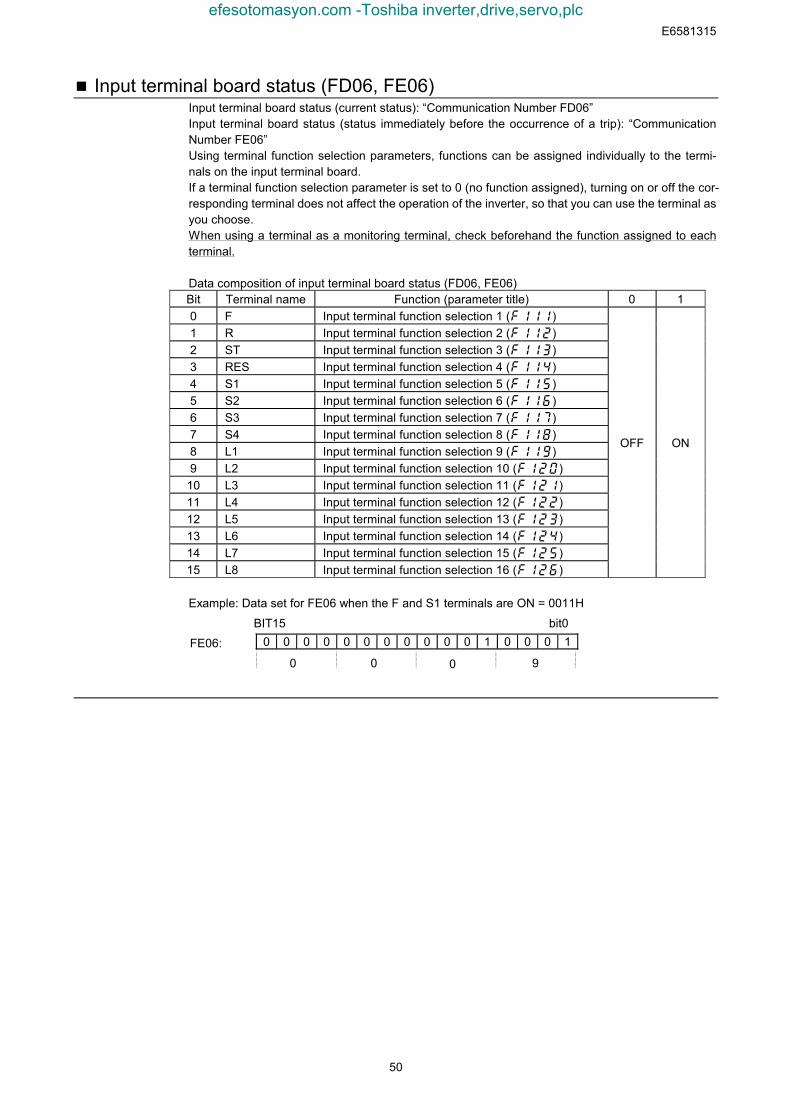
E6581315
50
Input terminal board status (FD06, FE06)Input terminal board status (current status): “Communication Number FD06”Input terminal board status (status immediately before the occurrence of a trip): “CommunicationNumber FE06”Using terminal function selection parameters, functions can be assigned individually to the termi-nals on the input terminal board.If a terminal function selection parameter is set to 0 (no function assigned), turning on or off the cor-responding terminal does not affect the operation of the inverter, so that you can use the terminal asyou choose.When using a terminal as a monitoring terminal, check beforehand the function assigned to eachterminal.
Data composition of input terminal board status (FD06, FE06)Bit Terminal name Function (parameter title) 0 10 F Input terminal function selection 1 (f111)1 R Input terminal function selection 2 (f112)2 ST Input terminal function selection 3 (f113)3 RES Input terminal function selection 4 (f114)4 S1 Input terminal function selection 5 (f115)5 S2 Input terminal function selection 6 (f116)6 S3 Input terminal function selection 7 (f117)7 S4 Input terminal function selection 8 (f118)8 L1 Input terminal function selection 9 (f119)9 L2 Input terminal function selection 10 (f120)
10 L3 Input terminal function selection 11 (f121)11 L4 Input terminal function selection 12 (f122)12 L5 Input terminal function selection 13 (f123)13 L6 Input terminal function selection 14 (f124)14 L7 Input terminal function selection 15 (f125)15 L8 Input terminal function selection 16 (f126)
OFF ON
Example: Data set for FE06 when the F and S1 terminals are ON = 0011H
0 0 0 0 0 0 0 0 0 0 0 1 0 0 0 1FE06:
0 900
bit0BIT15
efesotomasyon.com -Toshiba inverter,drive,servo,plc
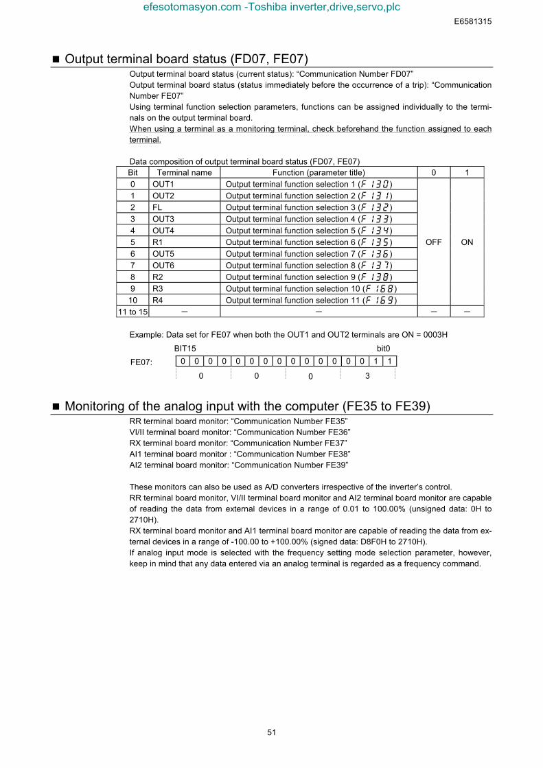
E6581315
51
Output terminal board status (FD07, FE07)Output terminal board status (current status): “Communication Number FD07”Output terminal board status (status immediately before the occurrence of a trip): “CommunicationNumber FE07”Using terminal function selection parameters, functions can be assigned individually to the termi-nals on the output terminal board.When using a terminal as a monitoring terminal, check beforehand the function assigned to eachterminal.
Data composition of output terminal board status (FD07, FE07)Bit Terminal name Function (parameter title) 0 10 OUT1 Output terminal function selection 1 (f130)1 OUT2 Output terminal function selection 2 (f131)2 FL Output terminal function selection 3 (f132)3 OUT3 Output terminal function selection 4 (f133)4 OUT4 Output terminal function selection 5 (f134)5 R1 Output terminal function selection 6 (f135)6 OUT5 Output terminal function selection 7 (f136)7 OUT6 Output terminal function selection 8 (f137)8 R2 Output terminal function selection 9 (f138)9 R3 Output terminal function selection 10 (f168)
10 R4 Output terminal function selection 11 (f169)
OFF ON
11 to 15 - - - -
Example: Data set for FE07 when both the OUT1 and OUT2 terminals are ON = 0003H
0 0 0 0 0 0 0 0 0 0 0 0 0 0 1 1FE07:
0 300
bit0BIT15
Monitoring of the analog input with the computer (FE35 to FE39)RR terminal board monitor: “Communication Number FE35”VI/II terminal board monitor: “Communication Number FE36”RX terminal board monitor: “Communication Number FE37”AI1 terminal board monitor : “Communication Number FE38”AI2 terminal board monitor: “Communication Number FE39”
These monitors can also be used as A/D converters irrespective of the inverter’s control.RR terminal board monitor, VI/II terminal board monitor and AI2 terminal board monitor are capableof reading the data from external devices in a range of 0.01 to 100.00% (unsigned data: 0H to2710H).RX terminal board monitor and AI1 terminal board monitor are capable of reading the data from ex-ternal devices in a range of -100.00 to +100.00% (signed data: D8F0H to 2710H).If analog input mode is selected with the frequency setting mode selection parameter, however,keep in mind that any data entered via an analog terminal is regarded as a frequency command.
efesotomasyon.com -Toshiba inverter,drive,servo,plc
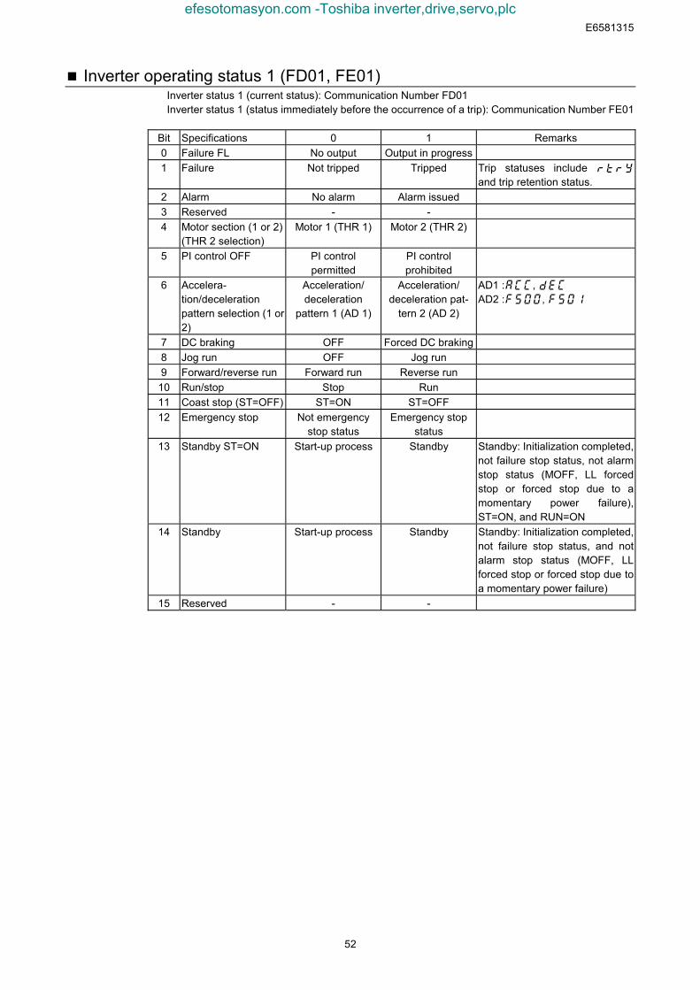
E6581315
52
Inverter operating status 1 (FD01, FE01)Inverter status 1 (current status): Communication Number FD01Inverter status 1 (status immediately before the occurrence of a trip): Communication Number FE01
Bit Specifications 0 1 Remarks0 Failure FL No output Output in progress1 Failure Not tripped Tripped Trip statuses include
and trip retention status.2 Alarm No alarm Alarm issued3 Reserved - -4 Motor section (1 or 2)
(THR 2 selection)Motor 1 (THR 1) Motor 2 (THR 2)
5 PI control OFF PI controlpermitted
PI controlprohibited
6 Accelera-tion/decelerationpattern selection (1 or2)
Acceleration/deceleration
pattern 1 (AD 1)
Acceleration/deceleration pat-
tern 2 (AD 2)
AD1 :, AD2 :,
7 DC braking OFF Forced DC braking8 Jog run OFF Jog run9 Forward/reverse run Forward run Reverse run
10 Run/stop Stop Run11 Coast stop (ST=OFF) ST=ON ST=OFF12 Emergency stop Not emergency
stop statusEmergency stop
status13 Standby ST=ON Start-up process Standby Standby: Initialization completed,
not failure stop status, not alarmstop status (MOFF, LL forcedstop or forced stop due to amomentary power failure),ST=ON, and RUN=ON
14 Standby Start-up process Standby Standby: Initialization completed,not failure stop status, and notalarm stop status (MOFF, LLforced stop or forced stop due toa momentary power failure)
15 Reserved - -
efesotomasyon.com -Toshiba inverter,drive,servo,plc
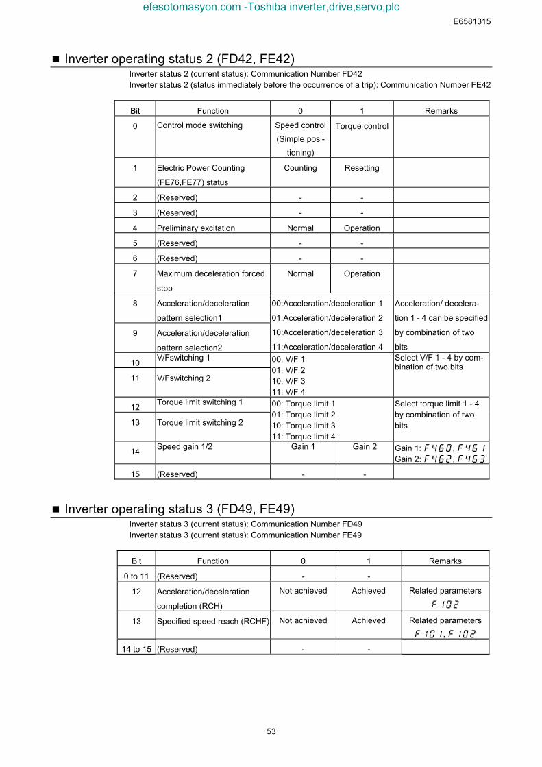
E6581315
53
Inverter operating status 2 (FD42, FE42)Inverter status 2 (current status): Communication Number FD42Inverter status 2 (status immediately before the occurrence of a trip): Communication Number FE42
Bit Function 0 1 Remarks
0 Control mode switching Speed control
(Simple posi-
tioning)
Torque control
1 Electric Power Counting
(FE76,FE77) status
Counting Resetting
2 (Reserved) - -
3 (Reserved) - -
4 Preliminary excitation Normal Operation
5 (Reserved) - -
6 (Reserved) - -
7 Maximum deceleration forced
stop
Normal Operation
8 Acceleration/deceleration
pattern selection1
9 Acceleration/deceleration
pattern selection2
00:Acceleration/deceleration 1
01:Acceleration/deceleration 2
10:Acceleration/deceleration 3
11:Acceleration/deceleration 4
Acceleration/ decelera-
tion 1 - 4 can be specified
by combination of two
bits
10 V/Fswitching 1
11 V/Fswitching 2
00: V/F 101: V/F 210: V/F 311: V/F 4
Select V/F 1 - 4 by com-bination of two bits
12 Torque limit switching 1
13 Torque limit switching 2
00: Torque limit 101: Torque limit 210: Torque limit 311: Torque limit 4
Select torque limit 1 - 4by combination of twobits
14 Speed gain 1/2 Gain 1 Gain 2 Gain 1: , Gain 2: ,
15 (Reserved) - -
Inverter operating status 3 (FD49, FE49)Inverter status 3 (current status): Communication Number FD49Inverter status 3 (current status): Communication Number FE49
Bit Function 0 1 Remarks
0 to 11 (Reserved) - -
12 Acceleration/deceleration
completion (RCH)
Not achieved Achieved Related parameters
f102
13 Specified speed reach (RCHF) Not achieved Achieved Related parameters
f101, f102
14 to 15 (Reserved) - -
efesotomasyon.com -Toshiba inverter,drive,servo,plc
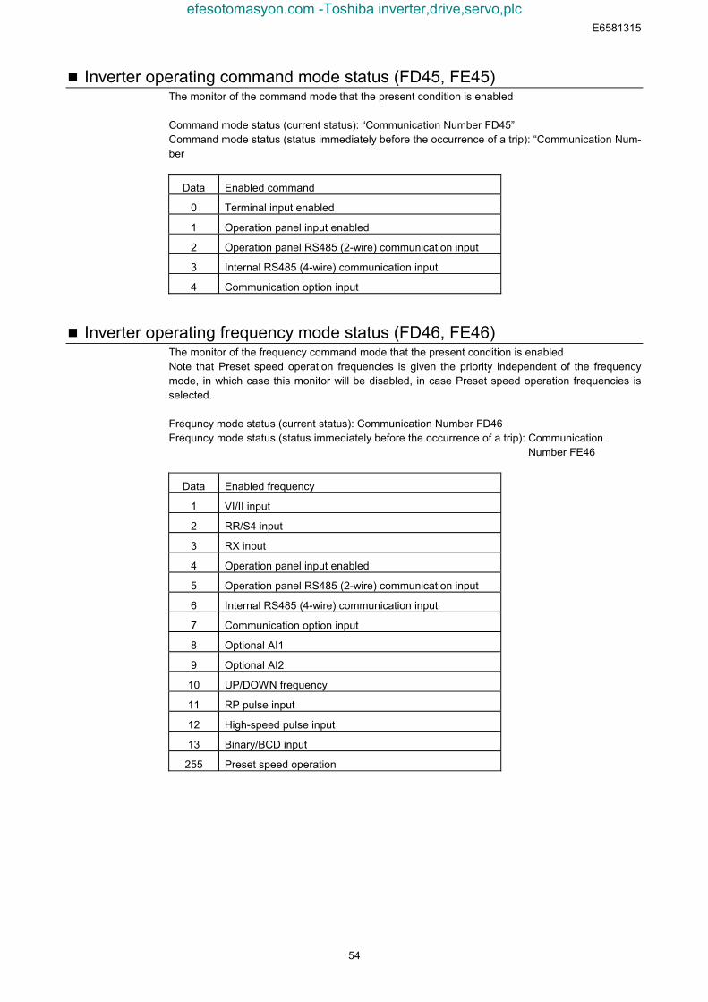
E6581315
54
Inverter operating command mode status (FD45, FE45)The monitor of the command mode that the present condition is enabled
Command mode status (current status): “Communication Number FD45”Command mode status (status immediately before the occurrence of a trip): “Communication Num-ber
Data Enabled command
0 Terminal input enabled
1 Operation panel input enabled
2 Operation panel RS485 (2-wire) communication input
3 Internal RS485 (4-wire) communication input
4 Communication option input
Inverter operating frequency mode status (FD46, FE46)The monitor of the frequency command mode that the present condition is enabledNote that Preset speed operation frequencies is given the priority independent of the frequencymode, in which case this monitor will be disabled, in case Preset speed operation frequencies isselected.
Frequncy mode status (current status): Communication Number FD46Frequncy mode status (status immediately before the occurrence of a trip): Communication
Number FE46
Data Enabled frequency
1 VI/II input
2 RR/S4 input
3 RX input
4 Operation panel input enabled
5 Operation panel RS485 (2-wire) communication input
6 Internal RS485 (4-wire) communication input
7 Communication option input
8 Optional AI1
9 Optional AI2
10 UP/DOWN frequency
11 RP pulse input
12 High-speed pulse input
13 Binary/BCD input
255 Preset speed operation
efesotomasyon.com -Toshiba inverter,drive,servo,plc
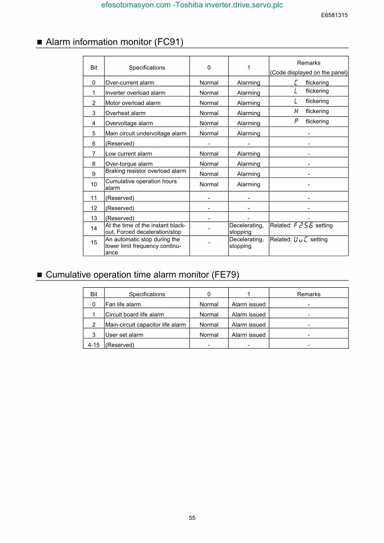
E6581315
55
Alarm information monitor (FC91)
Bit Specifications 0 1Remarks
(Code displayed on the panel)
0 Over-current alarm Normal Alarming flickering
1 Inverter overload alarm Normal Alarming flickering
2 Motor overload alarm Normal Alarming flickering
3 Overheat alarm Normal Alarming flickering
4 Overvoltage alarm Normal Alarming flickering
5 Main circuit undervoltage alarm Normal Alarming -
6 (Reserved) - - -
7 Low current alarm Normal Alarming -
8 Over-torque alarm Normal Alarming -
9 Braking resistor overload alarm Normal Alarming -
10 Cumulative operation hoursalarm Normal Alarming -
11 (Reserved) - - -
12 (Reserved) - - -
13 (Reserved) - - -
14 At the time of the instant black-out, Forced deceleration/stop - Decelerating,
stoppingRelated: setting
15 An automatic stop during thelower limit frequency continu-ance
- Decelerating,stopping
Related: setting
Cumulative operation time alarm monitor (FE79)
Bit Specifications 0 1 Remarks
0 Fan life alarm Normal Alarm issued -
1 Circuit board life alarm Normal Alarm issued -
2 Main-circuit capacitor life alarm Normal Alarm issued -
3 User set alarm Normal Alarm issued -
4-15 (Reserved) - - -
efesotomasyon.com -Toshiba inverter,drive,servo,plc
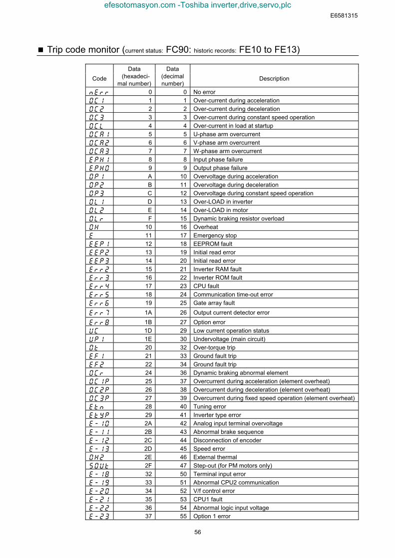
E6581315
56
Trip code monitor (current status: FC90: historic records: FE10 to FE13)
CodeData
(hexadeci-mal number)
Data(decimalnumber)
Description
nerr 0 0 No erroroc1 1 1 Over-current during accelerationoc2 2 2 Over-current during decelerationoc3 3 3 Over-current during constant speed operationocl 4 4 Over-current in load at startupocai 5 5 U-phase arm overcurrentoca2 6 6 V-phase arm overcurrentoca3 7 7 W-phase arm overcurrentephi 8 8 Input phase failureepho 9 9 Output phase failureop1 A 10 Overvoltage during accelerationop2 B 11 Overvoltage during decelerationop3 C 12 Overvoltage during constant speed operationol1 D 13 Over-LOAD in inverterol2 E 14 Over-LOAD in motorolr F 15 Dynamic braking resistor overloadoh 10 16 Overheate 11 17 Emergency stopeep1 12 18 EEPROM faulteep2 13 19 Initial read erroreep3 14 20 Initial read errorerr2 15 21 Inverter RAM faulterr3 16 22 Inverter ROM faulterr4 17 23 CPU faulterr5 18 24 Communication time-out errorerr6 19 25 Gate array faulterr7 1A 26 Output current detector errorerr8 1B 27 Option erroruc 1D 29 Low current operation statusup1 1E 30 Undervoltage (main circuit)ot 20 32 Over-torque tripef1 21 33 Ground fault tripef2 22 34 Ground fault tripocr 24 36 Dynamic braking abnormal elementoc1p 25 37 Overcurrent during acceleration (element overheat)oc2p 26 38 Overcurrent during deceleration (element overheat)oc3p 27 39 Overcurrent during fixed speed operation (element overheat)etn 28 40 Tuning erroretyp 29 41 Inverter type errore-10 2A 42 Analog input terminal overvoltagee-11 2B 43 Abnormal brake sequencee-12 2C 44 Disconnection of encodere-13 2D 45 Speed erroroh2 2E 46 External thermalsout 2F 47 Step-out (for PM motors only)e-18 32 50 Terminal input errore-19 33 51 Abnormal CPU2 communicatione-20 34 52 V/f control errore-21 35 53 CPU1 faulte-22 36 54 Abnormal logic input voltagee-23 37 55 Option 1 error
efesotomasyon.com -Toshiba inverter,drive,servo,plc
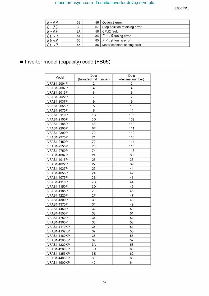
E6581315
57
e-24 38 56 Option 2 errore-25 39 57 Stop position retaining errore-26 3A 58 CPU2 faultetn1 54 84 tuning erroretn2 55 85 tuning erroretn3 56 86 Motor constant setting error
Inverter model (capacity) code (FB05)
Model Data(hexadecimal number)
Data(decimal number)
VFAS1-2004P 2 2VFAS1-2007P 4 4VFAS1-2015P 6 6VFAS1-2022P 7 7VFAS1-2037P 9 9VFAS1-2055P A 10VFAS1-2075P B 11VFAS1-2110P 6C 108VFAS1-2150P 6D 109VFAS1-2185P 6E 110VFAS1-2200P 6F 111VFAS1-2300P 70 112VFAS1-2370P 71 113VFAS1-2450P 72 114VFAS1-2550P 73 115VFAS1-2750P 74 116VFAS1-4007P 24 36VFAS1-4015P 26 38VFAS1-4022P 27 39VFAS1-4037P 29 41VFAS1-4055P 2A 42VFAS1-4075P 2B 43VFAS1-4110P 2C 44VFAS1-4150P 2D 45VFAS1-4185P 2E 46VFAS1-4220P 2F 47VFAS1-4300P 30 48VFAS1-4370P 31 49VFAS1-4450P 32 50VFAS1-4550P 33 51VFAS1-4750P 34 52VFAS1-4900P 35 53VFAS1-4110KP 36 54VFAS1-4132KP 37 55VFAS1-4160KP 38 56VFAS1-4200KP 39 57VFAS1-4220KP 3A 58VFAS1-4280KP 3C 60VFAS1-4355KP 3E 62VFAS1-4400KP 3F 63VFAS1-4500KP 40 64
efesotomasyon.com -Toshiba inverter,drive,servo,plc
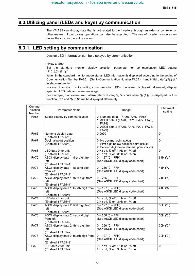
E6581315
58
8.3. Utilizing panel (LEDs and keys) by communicationThe VF-AS1 can display data that is not related to the inverters through an external controller orother means. Input by key operations can also be executed. The use of inverter resources re-duces the cost for the entire system.
8.3.1. LED setting by communicationDesired LED information can be displayed by communication.
<How to Set>Set the standard monitor display selection parameter to “communication LED setting(=).”When in the standard monitor mode status, LED information is displayed according to the setting ofCommunication Number FA65. (Set to Communication Number FA65 = 1 and initial data “”in shipment setting)In case of an alarm while setting communication LEDs, the alarm display will alternately displayspecified LED data and alarm message.For example, if an over-current alarm (alarm display “”) occurs while “.” is displayed by thisfunction, “” and “.” will be displayed alternately.
Commu-nicationNumber.
Parameter Name Range Shipmentsetting
FA65 Select display by communication 0: Numeric data (FA66, FA67, FA68)1: ASCII data 1 (FA70, FA71, FA72, FA73,
FA74)2: ASCII data 2 (FA75, FA76, FA77, FA78,
FA79)
1
FA66 Numeric display data(Enabled if FA65=0)
0-9999 0
FA67 Decimal point position(Enabled if FA65=0)
0: No decimal point (xxxx)1: First digit below decimal point (xxx.x)2: Second digit below decimal point (xx.xx)
0
FA68 LED data 0 for unit(Enabled if FA65=0)
0:Hz off, % off, 1:Hz on, % off2:Hz off, % on, 3:Hz on, % on
0
FA70 ASCII display data 1, first digit fromleft(Enabled if FA65=1)
0 – 127 (0 – 7FH)(See ASCII LED display code chart)
64H (’d’)
FA71 ASCII display data 1, second digitfrom left(Enabled if FA65=1)
0 – 256 (0 – FFH)(See ASCII LED display code chart)
41H (’A’)
FA72 ASCII display data 1, third digit fromleft(Enabled if FA65=1)
0 – 256 (0 – FFH)(See ASCII LED display code chart)
74H (’t’)
FA73 ASCII display data 1, fourth digit fromleft(Enabled if FA65=1)
0 – 127 (0 – 7FH)(See ASCII LED display code chart)
41H (’A’)
FA74 LED data 1 for unit(Enabled if FA65=1)
0:Hz off, % off, 1:Hz on, % off2:Hz off, % on, 3:Hz on, % on
0
FA75 ASCII display data 2, first digit fromleft(Enabled if FA65=2)
0 – 127 (0 – 7FH)(See ASCII LED display code chart)
30H (’0’)
FA76 ASCII display data 2, second digitfrom left(Enabled if FA65=2)
0 – 256 (0 – FFH)(See ASCII LED display code chart)
30H (’0’)
FA77 ASCII display data 2, third digit fromleft(Enabled if FA65=2)
0 – 256 (0 – FFH)(See ASCII LED display code chart))
30H (’0’)
FA78 ASCII display data 2, fourth digit fromleft(Enabled if FA65=2)
0 – 127 (0 – 7FH)(See ASCII LED display code chart)
30H (’0’)
FA79 LED data 2 for unit(Enabled if FA65=2)
0:Hz off, % off, 1:Hz on, % off2:Hz off, % on, 3:Hz on, % on
0
efesotomasyon.com -Toshiba inverter,drive,servo,plc
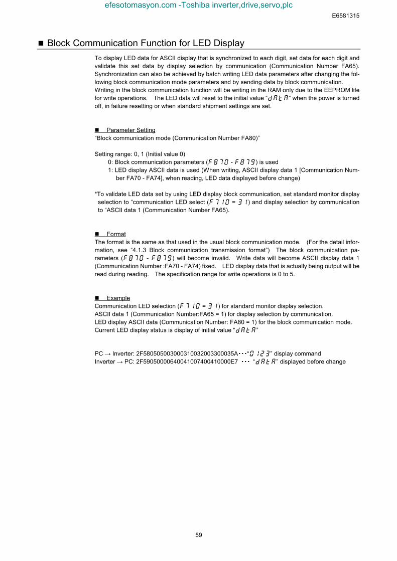
E6581315
59
Block Communication Function for LED DisplayTo display LED data for ASCII display that is synchronized to each digit, set data for each digit andvalidate this set data by display selection by communication (Communication Number FA65).Synchronization can also be achieved by batch writing LED data parameters after changing the fol-lowing block communication mode parameters and by sending data by block communication.Writing in the block communication function will be writing in the RAM only due to the EEPROM lifefor write operations. The LED data will reset to the initial value ““ when the power is turnedoff, in failure resetting or when standard shipment settings are set.
Parameter Setting“Block communication mode (Communication Number FA80)”
Setting range: 0, 1 (Initial value 0)0: Block communication parameters ( - ) is used1: LED display ASCII data is used (When writing, ASCII display data 1 [Communication Num-
ber FA70 - FA74], when reading, LED data displayed before change)
*To validate LED data set by using LED display block communication, set standard monitor displayselection to “communication LED select ( = ) and display selection by communicationto “ASCII data 1 (Communication Number FA65).
FormatThe format is the same as that used in the usual block communication mode. (For the detail infor-mation, see “4.1.3 Block communication transmission format”) The block communication pa-rameters ( - ) will become invalid. Write data will become ASCII display data 1(Communication Number :FA70 - FA74) fixed. LED display data that is actually being output will beread during reading. The specification range for write operations is 0 to 5.
ExampleCommunication LED selection ( = ) for standard monitor display selection.ASCII data 1 (Communication Number:FA65 = 1) for display selection by communication.LED display ASCII data (Communication Number: FA80 = 1) for the block communication mode.Current LED display status is display of initial value “”
PC → Inverter: 2F580505003000310032003300035A・・・“” display commandInverter → PC: 2F59050000640041007400410000E7 ・・・ “” displayed before change
efesotomasyon.com -Toshiba inverter,drive,servo,plc
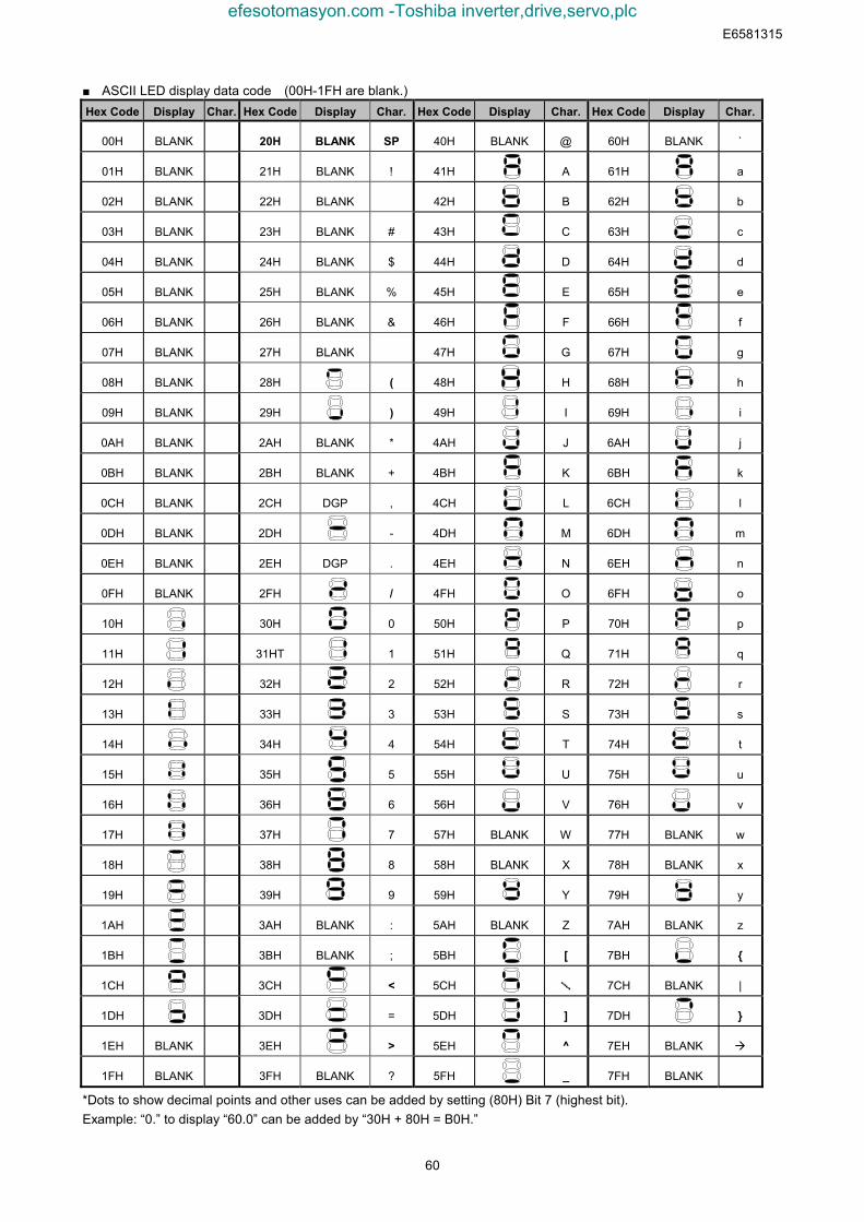
E6581315
60
■ ASCII LED display data code (00H-1FH are blank.)Hex Code Display Char. Hex Code Display Char. Hex Code Display Char. Hex Code Display Char.
00H BLANK 20H BLANK SP 40H BLANK @ 60H BLANK `
01H BLANK 21H BLANK ! 41H A 61H a
02H BLANK 22H BLANK 42H B 62H b
03H BLANK 23H BLANK # 43H C 63H c
04H BLANK 24H BLANK $ 44H D 64H d
05H BLANK 25H BLANK % 45H E 65H e
06H BLANK 26H BLANK & 46H F 66H f
07H BLANK 27H BLANK 47H G 67H g
08H BLANK 28H ( 48H H 68H h
09H BLANK 29H ) 49H I 69H i
0AH BLANK 2AH BLANK * 4AH J 6AH j
0BH BLANK 2BH BLANK + 4BH K 6BH k
0CH BLANK 2CH DGP , 4CH L 6CH l
0DH BLANK 2DH - 4DH M 6DH m
0EH BLANK 2EH DGP . 4EH N 6EH n
0FH BLANK 2FH / 4FH O 6FH o
10H 30H 0 50H P 70H p
11H 31HT 1 51H Q 71H q
12H 32H 2 52H R 72H r
13H 33H 3 53H S 73H s
14H 34H 4 54H T 74H t
15H 35H 5 55H U 75H u
16H 36H 6 56H V 76H v
17H 37H 7 57H BLANK W 77H BLANK w
18H 38H 8 58H BLANK X 78H BLANK x
19H 39H 9 59H Y 79H y
1AH 3AH BLANK : 5AH BLANK Z 7AH BLANK z
1BH 3BH BLANK ; 5BH [ 7BH {
1CH 3CH < 5CH \ 7CH BLANK |
1DH 3DH = 5DH ] 7DH }
1EH BLANK 3EH > 5EH ^ 7EH BLANK
1FH BLANK 3FH BLANK ? 5FH _ 7FH BLANK
*Dots to show decimal points and other uses can be added by setting (80H) Bit 7 (highest bit).Example: “0.” to display “60.0” can be added by “30H + 80H = B0H.”
efesotomasyon.com -Toshiba inverter,drive,servo,plc
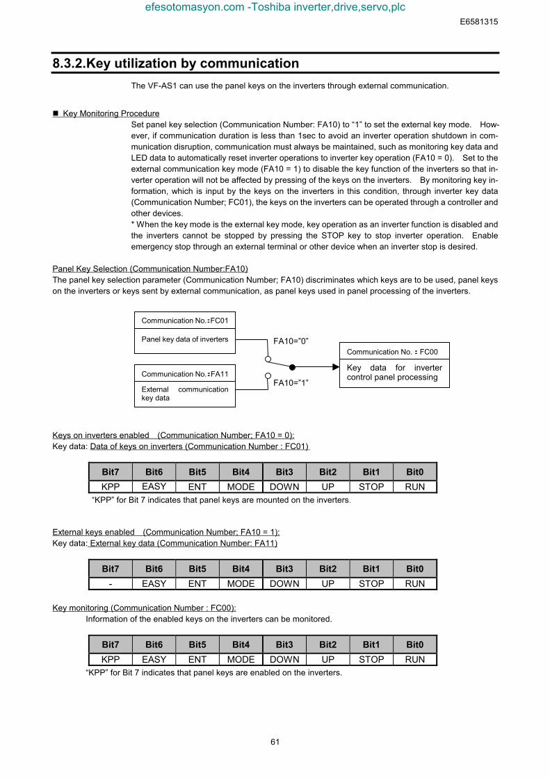
E6581315
61
8.3.2. Key utilization by communicationThe VF-AS1 can use the panel keys on the inverters through external communication.
Key Monitoring ProcedureSet panel key selection (Communication Number: FA10) to “1” to set the external key mode. How-ever, if communication duration is less than 1sec to avoid an inverter operation shutdown in com-munication disruption, communication must always be maintained, such as monitoring key data andLED data to automatically reset inverter operations to inverter key operation (FA10 = 0). Set to theexternal communication key mode (FA10 = 1) to disable the key function of the inverters so that in-verter operation will not be affected by pressing of the keys on the inverters. By monitoring key in-formation, which is input by the keys on the inverters in this condition, through inverter key data(Communication Number; FC01), the keys on the inverters can be operated through a controller andother devices.* When the key mode is the external key mode, key operation as an inverter function is disabled andthe inverters cannot be stopped by pressing the STOP key to stop inverter operation. Enableemergency stop through an external terminal or other device when an inverter stop is desired.
Panel Key Selection (Communication Number:FA10)The panel key selection parameter (Communication Number; FA10) discriminates which keys are to be used, panel keyson the inverters or keys sent by external communication, as panel keys used in panel processing of the inverters.
Keys on inverters enabled (Communication Number; FA10 = 0):Key data: Data of keys on inverters (Communication Number : FC01)
Bit7 Bit6 Bit5 Bit4 Bit3 Bit2 Bit1 Bit0KPP EASY ENT MODE DOWN UP STOP RUN
“KPP” for Bit 7 indicates that panel keys are mounted on the inverters.
External keys enabled (Communication Number; FA10 = 1):Key data: External key data (Communication Number: FA11)
Bit7 Bit6 Bit5 Bit4 Bit3 Bit2 Bit1 Bit0- EASY ENT MODE DOWN UP STOP RUN
Key monitoring (Communication Number : FC00):Information of the enabled keys on the inverters can be monitored.
Bit7 Bit6 Bit5 Bit4 Bit3 Bit2 Bit1 Bit0KPP EASY ENT MODE DOWN UP STOP RUN
“KPP” for Bit 7 indicates that panel keys are enabled on the inverters.
Panel key data of inverters
Communication No.:FC01
External communicationkey data
Communication No.:FA11Key data for invertercontrol panel processing
Communication No.:FC00FA10=”0”
FA10=”1”
efesotomasyon.com -Toshiba inverter,drive,servo,plc
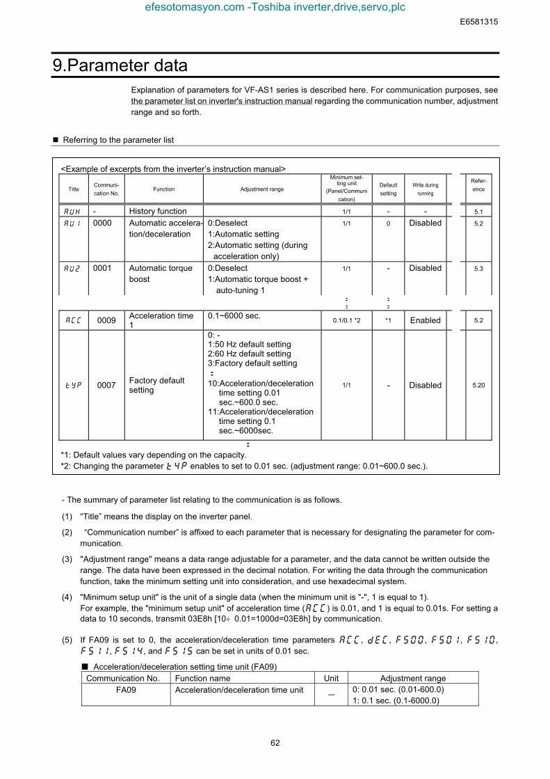
E6581315
62
9. Parameter dataExplanation of parameters for VF-AS1 series is described here. For communication purposes, seethe parameter list on inverter's instruction manual regarding the communication number, adjustmentrange and so forth.
Referring to the parameter list
<Example of excerpts from the inverter’s instruction manual>
TitleCommuni-cation No.
Function Adjustment range
Minimum set-ting unit
(Panel/Communication)
Defaultsetting
Write duringrunning
Refer-ence
auh - History function 1/1 - - 5.1
au1 0000 Automatic accelera-tion/deceleration
0:Deselect1:Automatic setting2:Automatic setting (during
acceleration only)
1/1 0 Disabled 5.2
au2 0001 Automatic torqueboost
0:Deselect1:Automatic torque boost +
auto-tuning 1
1/1 - Disabled 5.3
: :: :
acc 0009 Acceleration time1
0.1~6000 sec. 0.1/0.1 *2 *1 Enabled 5.2
typ 0007 Factory defaultsetting
0: -1:50 Hz default setting2:60 Hz default setting3:Factory default setting:10:Acceleration/deceleration
time setting 0.01sec.~600.0 sec.
11:Acceleration/decelerationtime setting 0.1sec.~6000sec.
1/1 - Disabled 5.20
:
*1: Default values vary depending on the capacity. *2: Changing the parameter enables to set to 0.01 sec. (adjustment range: 0.01~600.0 sec.).
- The summary of parameter list relating to the communication is as follows.
(1) “Title” means the display on the inverter panel.
(2) “Communication number” is affixed to each parameter that is necessary for designating the parameter for com-munication.
(3) "Adjustment range" means a data range adjustable for a parameter, and the data cannot be written outside therange. The data have been expressed in the decimal notation. For writing the data through the communicationfunction, take the minimum setting unit into consideration, and use hexadecimal system.
(4) "Minimum setup unit" is the unit of a single data (when the minimum unit is "-", 1 is equal to 1). For example, the "minimum setup unit" of acceleration time () is 0.01, and 1 is equal to 0.01s. For setting adata to 10 seconds, transmit 03E8h [10÷0.01=1000d=03E8h] by communication.
(5) If FA09 is set to 0, the acceleration/deceleration time parameters acc, dec, f500, f501, f510,f511, f514, and f515 can be set in units of 0.01 sec.
Acceleration/deceleration setting time unit (FA09)Communication No. Function name Unit Adjustment range
FA09 Acceleration/deceleration time unit-
0: 0.01 sec. (0.01-600.0)1: 0.1 sec. (0.1-6000.0)
efesotomasyon.com -Toshiba inverter,drive,servo,plc
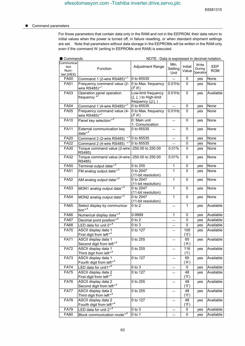
E6581315
63
Command parameters
For those parameters that contain data only in the RAM and not in the EEPROM, their data return toinitial values when the power is turned off, in failure resetting, or when standard shipment settingsare set. Note that parameters without data storage in the EEPROMs will be written in the RAM onlyeven if the command W (writing in EEPROMs and RAM) is executed.
Commands NOTE : Data is expressed in decimal notation.Communica-
tionNum-
ber.(HEX)
Function Adjustment Range Min.Setting
Unit
InitialValue
WriteDuring
Operation
EEPROM
FA00 Command 1 (2-wire RS485)*1 0 to 65535 - 0 yes NoneFA01 Frequency command value (2-
wire RS485)*10 to Max. frequency()
0.01Hz 0 yes None
FA03 Operation panel operationfrequency *2
Low-limit frequency() to High-limitfrequency ()
0.01Hz 0 yes Available
FA04 Command 1 (4-wire RS485)*1 0 to 65535 - 0 yes NoneFA05 Frequency command value (4-
wire RS485)*10 to Max. frequency()
0.01Hz 0 yes None
FA10 Panel key selection*4 0: Main unit1: Comunication
- 0 yes None
FA11 External communication keydata*4
0 to 65535 - 0 yes None
FA20 Command 2 (2-wire RS485) *1 0 to 65535 - 0 yes NoneFA22 Command 2 (4-wire RS485) *1 0 to 65535 - 0 yes NoneFA30 Torque command value (2-wire
RS485)-250.00 to 250.00 0.01% 0 yes None
FA32 Torque command value (4-wireRS485)
-250.00 to 250.00 0.01% 0 yes None
FA50 Terminal output data*3 0 to 255 1 0 yes NoneFA51 FM analog output data*3 0 to 2047
(11-bit resolution)1 0 yes None
FA52 AM analog output data*3 0 to 2047(11-bit resolution)
1 0 yes None
FA53 MON1 analog output data*3 0 to 2047(11-bit resolution)
1 0 yes None
FA54 MON2 analog output data*3 0 to 2047(11-bit resolution)
1 0 yes None
FA65 Select display by communica-tion*4
0 to 2 - 1 yes Available
FA66 Numerical display data*4 0-9999 1 0 yes AvailableFA67 Decimal point position*4 0 to 2 - 0 yes AvailableFA68 LED data for unit 0*4 0 to 3 - 0 yes AvailableFA70 ASCII display data 1
First digit from left*40 to 127 - 100
(‘d’)yes Available
FA71 ASCII display data 1Second digit from left*4
0 to 255 - 65(‘A’)
yes Available
FA72 ASCII display data 1Third digit from left*4
0 to 255 - 116(‘t’)
yes Available
FA73 ASCII display data 1Fourth digit from left*4
0 to 127 - 65(‘A’)
yes Available
FA74 LED data for unit1*4 0 to 3 - 0 yes AvailableFA75 ASCII display data 2
First digit from left*40 to 127 - 48
(‘0’)yes Available
FA76 ASCII display data 2Second digit from left*4
0 to 255 - 48(‘0’)
yes Available
FA77 ASCII display data 2Third digit from left*4
0 to 255 - 48(‘0’)
yes Available
FA78 ASCII display data 2Fourth digit from left*4
0 to 127 - 48(‘0’)
yes Available
FA79 LED data for unit 2*4 0 to 3 - 0 yes AvailableFA80 Block communication mode*4 0 to 1 - 0 yes Available
efesotomasyon.com -Toshiba inverter,drive,servo,plc

E6581315
64
*1: Enable the communication command or communication frequency setting before setting theseparameters are set. Otherwise, the parameters will not function. See “8.1 Command bycommunication” for the method to enable them.
*2: Note that the Communication Number for operation panel operation frequency is FA02 in theVF-S7 and VF-S9 series.
*3: See “8.1 Communication commands (commande from the computer)” for the detail information.*4: See “8.3 Utilizing panel (LEDs and keys) by communication” for the detail information.
efesotomasyon.com -Toshiba inverter,drive,servo,plc
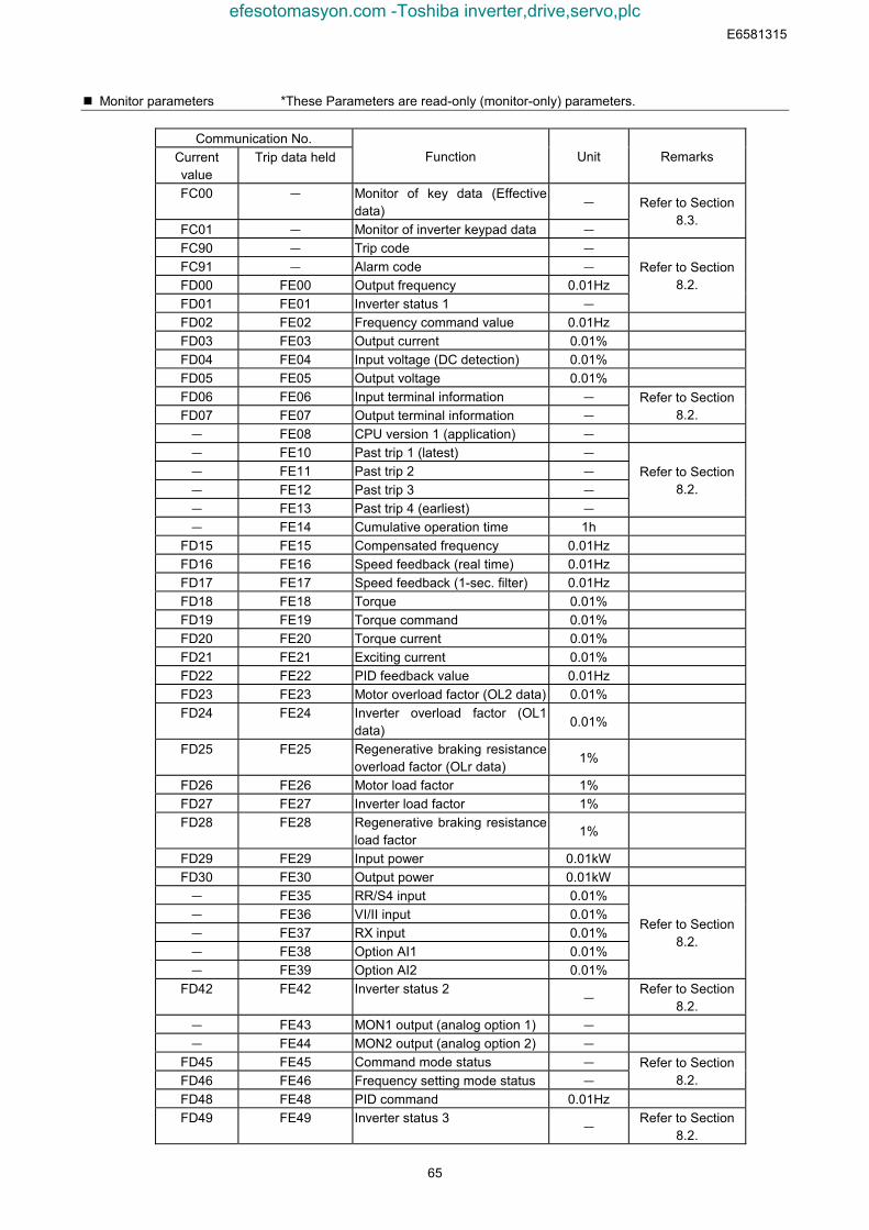
E6581315
65
Monitor parameters *These Parameters are read-only (monitor-only) parameters.
Communication No.Currentvalue
Trip data held Function Unit Remarks
FC00 - Monitor of key data (Effectivedata)
-
FC01 - Monitor of inverter keypad data -
Refer to Section8.3.
FC90 - Trip code -
FC91 - Alarm code -
FD00 FE00 Output frequency 0.01HzFD01 FE01 Inverter status 1 -
Refer to Section8.2.
FD02 FE02 Frequency command value 0.01HzFD03 FE03 Output current 0.01%FD04 FE04 Input voltage (DC detection) 0.01%FD05 FE05 Output voltage 0.01%FD06 FE06 Input terminal information -
FD07 FE07 Output terminal information -
Refer to Section8.2.
- FE08 CPU version 1 (application) -
- FE10 Past trip 1 (latest) -
- FE11 Past trip 2 -
- FE12 Past trip 3 -
- FE13 Past trip 4 (earliest) -
Refer to Section8.2.
- FE14 Cumulative operation time 1hFD15 FE15 Compensated frequency 0.01HzFD16 FE16 Speed feedback (real time) 0.01HzFD17 FE17 Speed feedback (1-sec. filter) 0.01HzFD18 FE18 Torque 0.01%FD19 FE19 Torque command 0.01%FD20 FE20 Torque current 0.01%FD21 FE21 Exciting current 0.01%FD22 FE22 PID feedback value 0.01HzFD23 FE23 Motor overload factor (OL2 data) 0.01%FD24 FE24 Inverter overload factor (OL1
data)0.01%
FD25 FE25 Regenerative braking resistanceoverload factor (OLr data)
1%
FD26 FE26 Motor load factor 1%FD27 FE27 Inverter load factor 1%FD28 FE28 Regenerative braking resistance
load factor1%
FD29 FE29 Input power 0.01kWFD30 FE30 Output power 0.01kW- FE35 RR/S4 input 0.01%- FE36 VI/II input 0.01%- FE37 RX input 0.01%- FE38 Option AI1 0.01%- FE39 Option AI2 0.01%
Refer to Section8.2.
FD42 FE42 Inverter status 2-
Refer to Section8.2.
- FE43 MON1 output (analog option 1) -
- FE44 MON2 output (analog option 2) -
FD45 FE45 Command mode status -
FD46 FE46 Frequency setting mode status -
Refer to Section8.2.
FD48 FE48 PID command 0.01HzFD49 FE49 Inverter status 3
-Refer to Section
8.2.
efesotomasyon.com -Toshiba inverter,drive,servo,plc

E6581315
66
FD50 - Light-load high-speed torque 1 0.01%FD51 - Light-load high-speed torque 2 0.01%- FE60 MY monitor 1 -
- FE61 MY monitor 2 -
- FE62 MY monitor 3 -
- FE63 MY monitor 4 -
- FE70 Rated current 0.1a- FE71 Rated voltage 0.1V- FE73 CPU version 2 (motor) -
- FE76 Integral input power 0.01kWh- FE77 Integral output power 0.01kWh- FE79 Part replacement alarm informa-
tion-
Refer to Section8.2.
- FE80 Cumulative power ON time 1hFD84 FE84 Binary input value (option) -
efesotomasyon.com -Toshiba inverter,drive,servo,plc
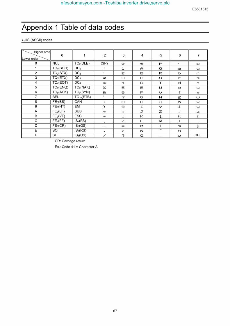
E6581315
67
Appendix 1 Table of data codes• JIS (ASCII) codes
Higher orde
Lower order0 1 2 3 4 5 6 7
0 NUL TC7(DLE) (SP) 0 @ P 、 p
1 TC1(SOH) DC1 ! 1 A Q a q
2 TC2(STX) DC2 ” 2 B R b r
3 TC3(ETX) DC3 # 3 C S c s
4 TC4(EOT) DC4 $ 4 D T d t
5 TC5(ENQ) TC8(NAK) % 5 E U e u
6 TC6(ACK) TC9(SYN) & 6 F V f v
7 BEL TC10(ETB) ’ 7 G W g w
8 FE0(BS) CAN ( 8 H X h x
9 FE1(HT) EM ) 9 I Y i y
A FE2(LF) SUB * : J Z j z
B FE3(VT) ESC + ; K [ k {
C FE4(FF) IS4(FS) , < L ¥ l |
D FE5(CR) IS3(GS) - = M ] m }
E SO IS2(RS) . > N ^ n ‾
F SI IS1(US) / ? O _ o DEL
CR: Carriage return
Ex.: Code 41 = Character A
efesotomasyon.com -Toshiba inverter,drive,servo,plc
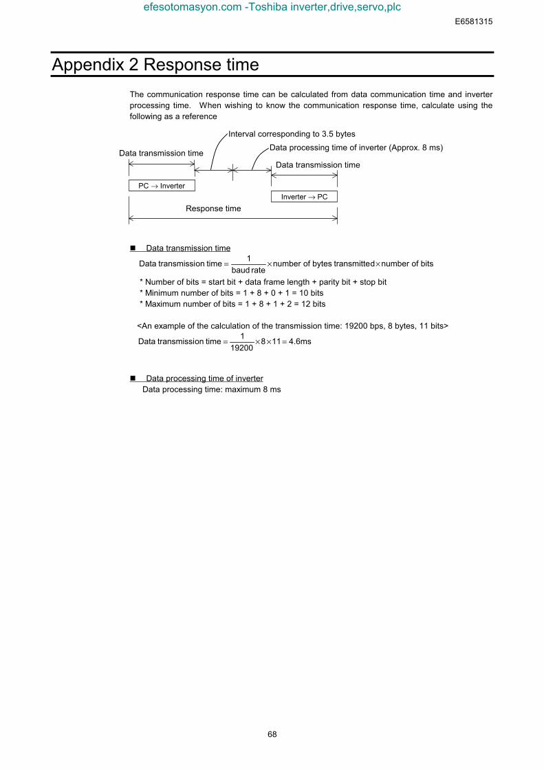
E6581315
68
Appendix 2 Response timeThe communication response time can be calculated from data communication time and inverterprocessing time. When wishing to know the communication response time, calculate using thefollowing as a reference
Data transmission time
bits of numberdtransmitte bytes of numberrate baud
1 time ontransmissi Data ××=
* Number of bits = start bit + data frame length + parity bit + stop bit* Minimum number of bits = 1 + 8 + 0 + 1 = 10 bits* Maximum number of bits = 1 + 8 + 1 + 2 = 12 bits
<An example of the calculation of the transmission time: 19200 bps, 8 bytes, 11 bits>
4.6ms11819200
1 time ontransmissi Data =××=
Data processing time of inverterData processing time: maximum 8 ms
Inverter → PC
Data transmission time
Response time
PC → Inverter
Data transmission time
Interval corresponding to 3.5 bytesData processing time of inverter (Approx. 8 ms)
efesotomasyon.com -Toshiba inverter,drive,servo,plc
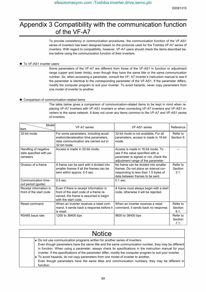
E6581315
69
Appendix 3 Compatibility with the communication functionof the VF-A7
To provide consistency in communication procedures, the communication function of the VF-AS1series of inverters has been designed based on the protocols used for the Toshiba VF-A7 series ofinverters. With regard to compatibility, however, VF-A7 users should check the items described be-low before using the communication function of their inverters.
To VF-AS1 inverter users:Some parameters of the VF-A7 are different from those of the VF-AS1 in function or adjustmentrange (upper and lower limits), even though they have the same title or the same communicationnumber. So, when accessing a parameter, consult the VF- A7 inverter’s instruction manual to see ifthe parameter is identical to the corresponding parameter of the VF-AS1. If the parameter differs,modify the computer program to suit your inverter. To avoid hazards, never copy parameters fromone model of inverter to another.
Comparison of communication-related itemsThe table below gives a comparison of communication-related items to be kept in mind when re-placing VF-A7 inverters with VF-AS1 inverters or when connecting VF-A7 inverters and VF-AS1 in-verters to the same network. It does not cover any items common to the VF-A7 and VF-AS1 seriesof inverters.
ModelItem VF-A7 series VF-AS1 series Reference
32-bit mode For some parameters, including accel-eration/deceleration time parameters,data communication are carried out in32-bit mode.
32-bit mode is not available. For allparameters, access is made in 16-bitmode.
Refer toSection 9.
Handling of negativedata specified with pa-rameters
Access is made in 32-bit mode. Access is made in 16-bit mode. Tosee if the value specified with aparameter is signed or not, check theadjustment range of the parameter.
-
Division of a frame A frame can be sent with it divided intosmaller frames if all the frames can besent within approx. 0.5 sec.
No frame can be divided into smallerframes. Do not place an interval cor-responding to less than 1.5 bytes ofdata between frames to be sent.
Communication time-out period (guide)
0.5 sec. 0.1 sec.
Receipt information infront of the start code
Even if there is receipt information infront of the start code of a frame re-ceived, the frame is assumed to beginwith the start code.
A frame must always begin with a startcode, otherwise it will be rejected.
Refer toSection
3.1.
Reset command When an inverter receives a reset com-mand, it sends back a response before itis reset.
When an inverter receives a resetcommand, it sends back no response.
Refer toSection
8.1.RS485 baud rate 1200 to 38400 bps 9600 to 38400 bps Refer to
Section7.1.
Notice♦ Do not use communication programs written for another series of inverters.
Even though parameters have the same title and the same communication number, they may be differentin function. When using a parameter, always check its specifications in the instruction manual for yourinverter. If the specifications of the parameter differ, modify the computer program to suit your inverter.
♦ To avoid hazards, do not copy parameters from one model of inverter to another.Even though parameters have the same titles and communication numbers, they may be different infunction.
efesotomasyon.com -Toshiba inverter,drive,servo,plc
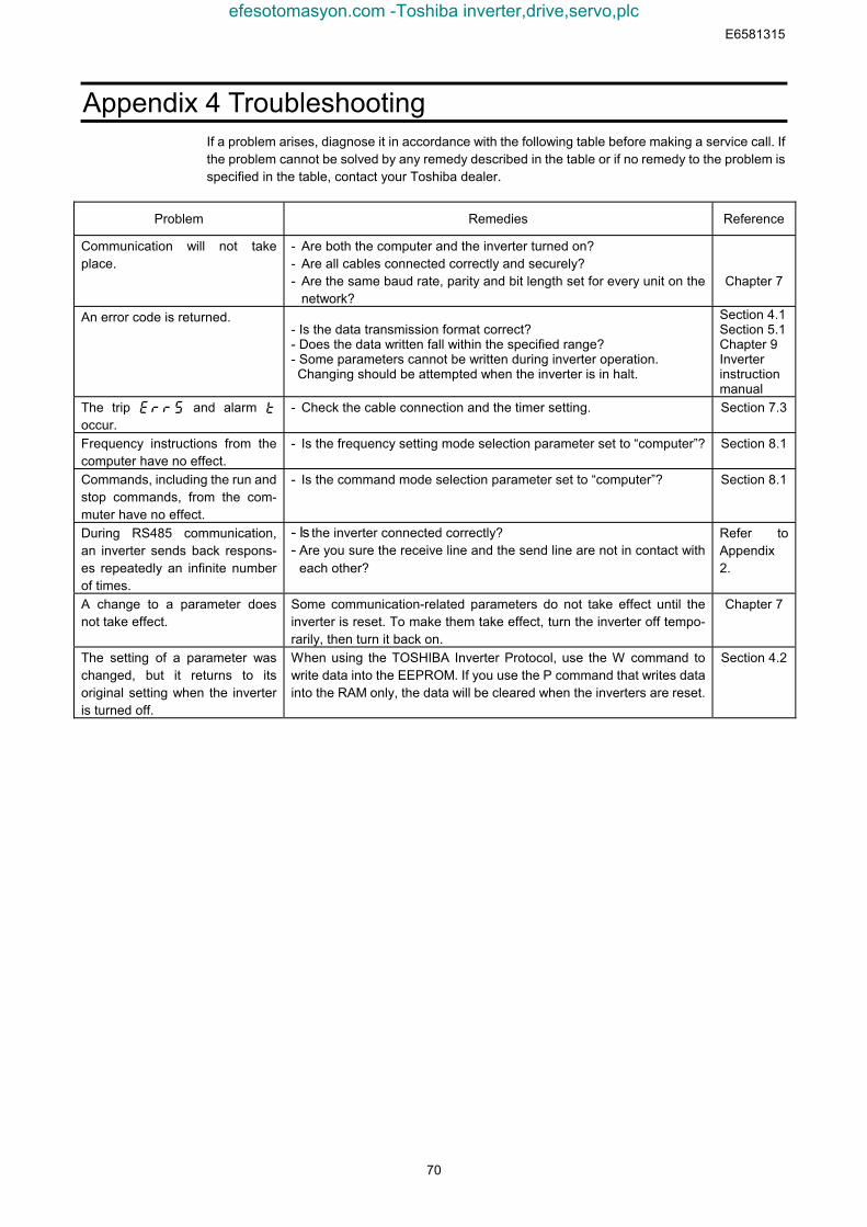
E6581315
70
Appendix 4 TroubleshootingIf a problem arises, diagnose it in accordance with the following table before making a service call. Ifthe problem cannot be solved by any remedy described in the table or if no remedy to the problem isspecified in the table, contact your Toshiba dealer.
Problem Remedies Reference
Communication will not takeplace.
- Are both the computer and the inverter turned on?- Are all cables connected correctly and securely?- Are the same baud rate, parity and bit length set for every unit on the
network?Chapter 7
An error code is returned.- Is the data transmission format correct?- Does the data written fall within the specified range?- Some parameters cannot be written during inverter operation. Changing should be attempted when the inverter is in halt.
Section 4.1Section 5.1Chapter 9Inverterinstructionmanual
The trip err5 and alarm toccur.
- Check the cable connection and the timer setting. Section 7.3
Frequency instructions from thecomputer have no effect.
- Is the frequency setting mode selection parameter set to “computer”? Section 8.1
Commands, including the run andstop commands, from the com-muter have no effect.
- Is the command mode selection parameter set to “computer”? Section 8.1
During RS485 communication,an inverter sends back respons-es repeatedly an infinite numberof times.
- Is the inverter connected correctly?- Are you sure the receive line and the send line are not in contact with
each other?
Refer toAppendix2.
A change to a parameter doesnot take effect.
Some communication-related parameters do not take effect until theinverter is reset. To make them take effect, turn the inverter off tempo-rarily, then turn it back on.
Chapter 7
The setting of a parameter waschanged, but it returns to itsoriginal setting when the inverteris turned off.
When using the TOSHIBA Inverter Protocol, use the W command towrite data into the EEPROM. If you use the P command that writes datainto the RAM only, the data will be cleared when the inverters are reset.
Section 4.2
efesotomasyon.com -Toshiba inverter,drive,servo,plc
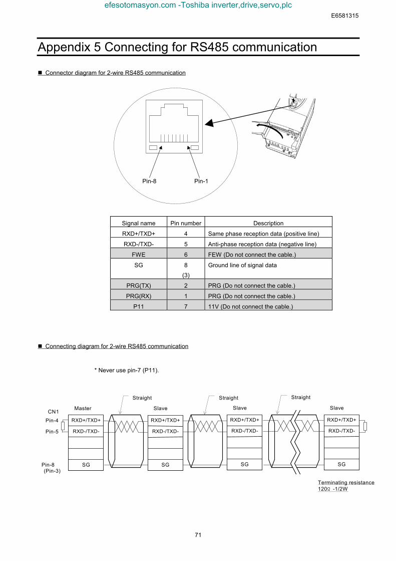
E6581315
71
Appendix 5 Connecting for RS485 communication
Connector diagram for 2-wire RS485 communication
Connecting diagram for 2-wire RS485 communication
* Never use pin-7 (P11).
Master
RXD+/TXD+
RXD-/TXD-
SG
CN1
Pin-4
Pin-5
Pin-8(Pin-3)
Straight Straight
Terminating resistance120Ω-1/2W
Straight
Slave
RXD+/TXD+
RXD-/TXD-
SG
Slave
RXD+/TXD+
RXD-/TXD-
SG
Slave
RXD+/TXD+
RXD-/TXD-
SG
Signal name Pin number Description
RXD+/TXD+ 4 Same phase reception data (positive line)
RXD-/TXD- 5 Anti-phase reception data (negative line)
FWE 6 FEW (Do not connect the cable.)
SG 8
(3)
Ground line of signal data
PRG(TX) 2 PRG (Do not connect the cable.)
PRG(RX) 1 PRG (Do not connect the cable.)
P11 7 11V (Do not connect the cable.)
Pin-1Pin-8
efesotomasyon.com -Toshiba inverter,drive,servo,plc
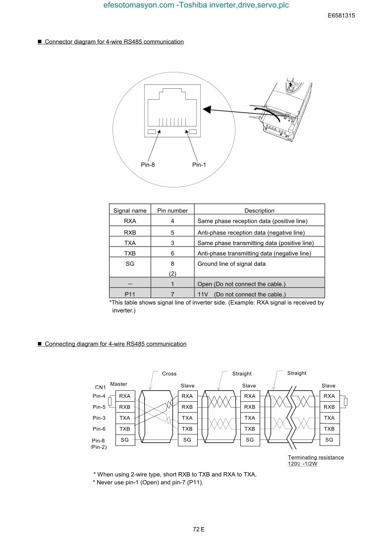
E6581315
72
Connector diagram for 4-wire RS485 communication
Connecting diagram for 4-wire RS485 communication
* When using 2-wire type, short RXB to TXB and RXA to TXA.* Never use pin-1 (Open) and pin-7 (P11).
Terminating resistance120Ω-1/2W
Slave Slave SlaveCN1 Master
RXA
RXB
TXA
TXB
SG
RXA
RXB
TXA
TXB
SG
RXA
RXB
TXA
TXB
SG
RXA
RXB
TXA
TXB
SG
Cross Straight Straight
Pin-4
Pin-5
Pin-3
Pin-6
Pin-8(Pin-2)
Pin-1Pin-8
Signal name Pin number Description
RXA 4 Same phase reception data (positive line)
RXB 5 Anti-phase reception data (negative line)
TXA 3 Same phase transmitting data (positive line)
TXB 6 Anti-phase transmitting data (negative line)
SG 8
(2)
Ground line of signal data
- 1 Open (Do not connect the cable.)
P11 7 11V (Do not connect the cable.)*This table shows signal line of inverter side. (Example: RXA signal is received byinverter.)
E
efesotomasyon.com -Toshiba inverter,drive,servo,plc