toshibaʼs co capture at mikawathermal power...
TRANSCRIPT

© 2018 Toshiba Energy Systems & Solutions CorporationPRD-GXM-CCS-0137 R0
June 18, 2018
Toshibaʼs CO2 Captureat Mikawa Thermal Power Plant
Japan CCS Forum 2018
Thermal & Hydro Power Systems & Services DivisionToshiba Energy Systems & Solutions Corporation
Kensuke Suzuki

2© 2018 Toshiba Energy Systems & Solutions CorporationPRD-GXM-CCS-0137 R0
Contents
1. Background2. Application of CO2 Capture to Thermal Power Plants3. CO2 Capture at Mikawa Thermal Power Plant4. Summary

3© 2018 Toshiba Energy Systems & Solutions CorporationPRD-GXM-CCS-0137 R0
Toshiba Energy Systems & Solutions CorporationEnergy Business Domain
Toshiba Digital Solutions Corporation
Satoshi Tsunakawa
Board of Directors
Toshiba Infrastructure Systems & Solutions Corporation
TOSHIBA Building (HQ for Toshiba Corporation)
LAZONA Kawasaki TOSHIBA building)(HQ for Toshiba Energy Systems & Solutions Corporation)
Social Infrastructure Business Domain
Digital Solutions Business Domain
As of April 2018
Toshiba Tec Corporation
Toshiba Electronic Devices & Storage CorporationElectrical Devices Business Domain
Toshiba Memory Corporation
TOSHIBA CORPORATION
Chairman & CEO
Nobuaki Kurumatani
President & COO
Toshiba Client Solutions Co., Ltd.
Toshiba Corporate Profile

4© 2018 Toshiba Energy Systems & Solutions CorporationPRD-GXM-CCS-0137 R0
Business Domain
Nuclear Power
Transmission and Distribution / Energy Storage
Thermal Power
Power Generation Systems
Renewable Energy
Transformer Supervisory Control And Data Acquisition Systems (SCADA)
Hydrogen-based Autonomous Energy Supply System
Stationary Battery Energy Storage Systems
Heavy-Ion Radiotherapy SystemFor Cancer Treatment
Geothermal Power Hydro Power Solar Power
Toshiba Energy Systems & Services Corporation

5© 2018 Toshiba Energy Systems & Solutions CorporationPRD-GXM-CCS-0137 R0
Toshiba Turbine Power Plants Supplied Worldwide
Note: Units manufactured by Toshiba Keihin Product Operations and TJPS(Toshiba JSW Power Systems Pvt. Ltd.)
UK1(210)
Cyprus2(120)
Egypt6(1,764)
Nigeria4(56)
Botswana1(33)South Africa2(118)
Kuwait22(4,470)
Turkey3(152)
Bulgaria3(532)
Italy4(994)
Lebanon4(130)
Kenya4(300)
Pakistan3(137)
Sri Lanka1(6)
Bahrain1(65)
Iceland1(34)
India30(10,483)
Bangladesh5(41)
Myanmar2(0.9)
Thailand8(348)
Malaysia27(5,688)
Vietnam8(4,888)
China(incl. Taiwan Region)51(13,637)
Korea34(4,220)Japan1,460(82,807)
Philippines27(1,114)
Australia55(11,672)
New Zealand2(167)
Nauru1(0.1)
Papua New Guinea3(135)
Canada10(1,427)
Mexico31(2,754)
Costa Rica1(55) Venezuela
7(1,418)
Antigua2(18)
Puerto Rico1(214)
Brazil3(155)
Argentina3(14)
Indonesia21(4,692)
Iran4(255)
UAE8(6,528)
USA115(38,719)
CountryUnit(MW)
Total : 1,983 Units / 201,220 MW(As of December 2017)

6© 2018 Toshiba Energy Systems & Solutions CorporationPRD-GXM-CCS-0137 R0
Plant Net Efficiency (LHV)
CO
2 E
mis
sion
s (g
ram
s / k
Wh)
Substantial CO2 reduction is realized by Integration and Optimization ofboth High efficiency Turbine Cycles and CCS technology
CO2 Reduction for Coal Thermal Power Plants
0
200
400
600
800
1000
1200
1400
30 35 40 45 50 55 60
A-USC
Sub Critical
USC
USC+CCS( 90% CO2 Capture )
A-USC+CCS( 90% CO2 Capture )
1100 lbs-CO2 / MWh

7© 2018 Toshiba Energy Systems & Solutions CorporationPRD-GXM-CCS-0137 R0
Contents
1. Background2. Application of CO2 Capture to Thermal Power Plants3. CO2 Capture at Mikawa Thermal Power Plant4. Summary

8© 2018 Toshiba Energy Systems & Solutions CorporationPRD-GXM-CCS-0137 R0
ASU: Air Separation Unit FGD: Fuel Gas Desulphurization EP: Electrostatic Precipitator
Boiler DeNOx EP FGD CO2 Capture
CO2H2ON2 H2O
N2O2
Fuel Air
Boiler EP FGD
CO2H2OO2
H2O
FuelASU
AirO2
GasifierFuel
ASUAirO2
CO2 Capture
CO2COH2OH2
H2O CO2H2 H2
Gas Turbine
CO2 Capture
Post Combustion Capture (PCC)
CO2
ShiftReactor
DeNOx/FGD
CO2
CO2
Oxy-Fuel (Firing)
Pre Combustion Capture
PROS:- Capture process after boiler simplified- Little penalty associated with capture itself
CONS:- Energy penalty and cost required for ASU- Plant operational flexibility - Additional equip required for CO2 purity- No partial capture configuration possible
PROS:- Process proven in chemical industry- Adaptable to new build, existing retros- Adaptable to other emitters (steel, cement)- Partial capture configuration possible
CONS:- Energy penalty for capture- Equipments tend to be larger than other techs
PROS:- Capture equipments smaller (high pressure)- Capture energy penalty smaller
CONS:- Energy penalty and cost required for ASU- IGCC lacks operational flexibility of CC - Only new build application- No partial capture configuration possible
CO2 Capture Technology for Thermal Power Plants

9© 2018 Toshiba Energy Systems & Solutions CorporationPRD-GXM-CCS-0137 R0
Stack
Condenser
CEP BFP
Steam Turbine& Generator
Absorber
Stripper
LiquefiedCO2
Reboiler
DeaeLP Heaters HP Heaters
Extraction Steam System
Drain Recovery System
CO2 Compressor
HIP
CO2 Capture Plant
AdditionalFGD
ESPIDF
Boiler
Flue gas treatment
GAH
G LP -ALP -B
1. Integration toFlue Gas System
Integration of Carbon Capture to Thermal Power Plants
2. Integration toPower System & Cycle
Utility Facilities
Waste Water Treatment
Water Supply System
Control and Service Air
CoolingWater
Cooling Tower
Auxiliary power
3. Integration withPlant Utility Systems
4. Integration with Power PlantOperation and Maintenance

10© 2018 Toshiba Energy Systems & Solutions CorporationPRD-GXM-CCS-0137 R0
CO2 Capture Technology Implementation Flow
E-1 Stirpper
E-3
E-4
E-5
E-6
P-1
P-2P-3
P-6
P-7
P-8
E-7
P-9
P-10
P-11
E-8
P-12
P-14
E-11E-12
P-15
P-16
P-17
P-18
P-19
P-20
I-1
V-1 P-21
P-23
E-13
I-2
P-25 P-26P-27
E-16
P-33 P-34
I-4
V-3 P-35
P-36
I-5
P-38
E-17
P-39P-38
E-18
P-40
E-19
P-41
P
I-6P-42 P-9
T
I-7
P-43
I-8
T
I-9
P-10
T
I-10
P-45
P-11
T
I-11
T
I-12
P-46
P-13
P-47 P-7
T
I-13
P-48P-33
P
I-14 P-49
P
I-16
P-50
P-11
P-51
P-52
N2 NOxSOxCO2O2
I-1I-1I-1I-1I-1
GC
LC
GCGC
LC
Screening of Absorbents andEvaluation of SystemPerformance Improvementby Simulation
Evaluation of Basic Propertiesand Absorption Performance
Performance / DegradationEvaluation by Small Loop
Overall Demonstration atMikawa - PCC Pilot Plant
Large Scale Demonstration/ Commercial Plant

11© 2018 Toshiba Energy Systems & Solutions CorporationPRD-GXM-CCS-0137 R0
CO2 Capture Plant Deployment
Mikawa* Post Combustion Capture Pilot PlantCommenced: Sep.2009Captures 10 tons of CO2 per day
from flue gas of Mikawa ThermalPower Plant.
Saga City CCU PlantCommenced: Sep.2016Captures 10 tons of CO2 per day from
flue gas of Saga City waste incinerationplant for use in agriculture.
Ministry of the EnvironmentSustainable CCS ProjectCO2 Capture Demonstration PlantCommence: Summer 2020 (Scheduled)Will capture more than 500 tons of CO2
per day from flue gas of Mikawa ThermalPower Plant.* Mikawa Thermal Power Plant – Property of SIGMA POWER Ariake Co.Ltd.

12© 2018 Toshiba Energy Systems & Solutions CorporationPRD-GXM-CCS-0137 R0
Contents
1. Background2. Application of CO2 Capture to Thermal Power Plants3. CO2 Capture at Mikawa Thermal Power Plant4. Summary

13© 2018 Toshiba Energy Systems & Solutions CorporationPRD-GXM-CCS-0137 R0
Mikawa Thermal Power Plant
CFB Boiler(Biomass/Coal)
Turbine No.1
Turbine No.2
CO2 CapturePilot Plant
49MW Commercial
Full SizeSteam Turbine
Test Facility
Stackfluegas
steam IoT ServerData Collection &
Remote monitoring
CO2 CaptureDemonstration Plant
Constructed for the Ministry of the
Environment ProjectToshiba owned
Sigma Power Ariake Co., Ltd.Mikawa Power PlantOmuta City, Fukuoka, Japan
Tokyo
Omuta
PC Boiler(Not Used)
14© 2018 Toshiba Energy Systems & Solutions CorporationPRD-GXM-CCS-0137 R0
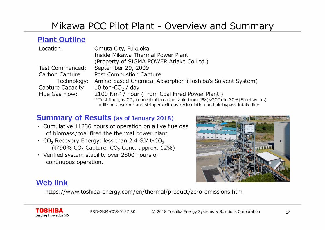
Summary of Results (as of January 2018)
Plant Outline
・ Cumulative 11236 hours of operation on a live flue gasof biomass/coal fired the thermal power plant
・ CO2 Recovery Energy: less than 2.4 GJ/ t-CO2(@90% CO2 Capture, CO2 Conc. approx. 12%)
・ Verified system stability over 2800 hours ofcontinuous operation.
Location: Omuta City, FukuokaInside Mikawa Thermal Power Plant(Property of SIGMA POWER Ariake Co.Ltd.)
Test Commenced: September 29, 2009Carbon Capture Post Combustion Capture
Technology: Amine-based Chemical Absorption (Toshibaʼs Solvent System)Capture Capacity: 10 ton-CO2 / dayFlue Gas Flow: 2100 Nm3 / hour ( from Coal Fired Power Plant )
* Test flue gas CO2 concentration adjustable from 4%(NGCC) to 30%(Steel works)utilizing absorber and stripper exit gas recirculation and air bypass intake line.
Mikawa PCC Pilot Plant - Overview and Summary
Web linkhttps://www.toshiba-energy.com/en/thermal/product/zero-emissions.htm

15© 2018 Toshiba Energy Systems & Solutions CorporationPRD-GXM-CCS-0137 R0
Post Combustion CO2 Capture Pilot Plant

16© 2018 Toshiba Energy Systems & Solutions CorporationPRD-GXM-CCS-0137 R0
Solvent Sampling and Evaluation
Material Test Piece and Evaluation
PCC Pilot Plant Verification
Evaluation of Plant Operability
Solvent Purification Test
Plant Start-Up and Shutdown
Plant OperabilityO&M Evaluation
Evaluation ofLong TermPlant Performance(Solvents, Materials)
17© 2018 Toshiba Energy Systems & Solutions CorporationPRD-GXM-CCS-0137 R0
Ministry of the Environment Sustainable CCS ProjectOutline of the Project(1) CO2 Capture from the Mikawa Power Plant・ CO2 capture facility to be designed and constructed to capture more than 500 tons of CO2 per day.
(500 tons of CO2 per day is about 50% of the daily emissions from the 49 MW Mikawa Power Plant)・ The plant will be used to evaluate performance of technology under various operating conditions,
cost and environmental aspects of the amine-based post-combustion chemical absorption technology.(2) Establishing a Socio-political Environment for the Introduction of CCS in Japan・ Research on aspects including socio-economics and policies to establish an enabling environment
necessary for the smooth introduction of CCS in Japan.・ Develop basic concepts toward an integrated CCS system, with aims to achieve practical applications
of the capture technology by 2020.
Project Consortium (as of March 2018)Project Representative: Toshiba Energy Systems & Solutions CorporationProject Administrator : Mizuho Information & Research Institute, Inc. Consortium Members: Chiyoda Corporation
JGC CorporationMitsubishi Materials CorporationTaisei CorporationDia Consultants Co., Ltd.QJ Science Ltd.Japan NUS Co., Ltd.National Institute of Advanced Industrial Science and Technology (AIST)Central Research Institute of Electric Power Industry (CRIEPI)The University of TokyoKyushu University
Project Leader : Dr. Makoto Akai (Emeritus Researcher at AIST)

18© 2018 Toshiba Energy Systems & Solutions CorporationPRD-GXM-CCS-0137 R0
The CO2 Capture Demonstration Plant will be designed and built to capture more than 500 tons-CO2/day from Mikawa Power Plant (more than 50% of its total emissions)
The Capture Plant will be built and fully integrated with the Power Plant, with turbine extraction steam feeding the energy for regeneration of CO2 at the stripper tower.
The old coal boiler was replaced with a boiler capable of also burning 100% biomass. The new boiler is now fully operational and normally operating on biomass fuel. Consequently, the project may become one of the first BECCS project in the world.
MoE Project – CO2 Capture Demonstration Plant

19© 2018 Toshiba Energy Systems & Solutions CorporationPRD-GXM-CCS-0137 R0
Layout of CO2 Capture Demonstration Plant
Planned Location of the CO2 Capture Demo Plant
PCC Pilot Plant(Existing)
CO2 CaptureDemo Plant
Planned Layout of CO2 Capture Demo Plant
AbsorberTower
StripperTower
CoolingTower

20© 2018 Toshiba Energy Systems & Solutions CorporationPRD-GXM-CCS-0137 R0
FY2016 FY2017 FY2018 FY2019 FY2020
CO2 Capture PlantConstruction &Demonstration
Evaluation of EnvironmentalEffects and Control of CO2 Capture Plant(with Mizuho I&R)
Schedule of CO2 Capture Demonstration Plant
Detailed Design ofCapture Plant
Design of ExistingPlant Modification
Permitting & SecuringLand for Construction
Demo Plant Construction& Integration to Power Plant
Plant Commissioning& Demonstration
Study on Environment Monitoring& Risk Evaluation Method Improvement
Study on using Bioresponse Test for EnvironmentEffect Evaluation & Risk Evaluation Method
Evaluation of ExistingBaseline Emission
Evaluation of EmissionMitigation Methods
Evaluation of Emissionfrom Demo Plant
Gathering of Information and Revision of Proposed Guideline Proposing Guideline

21© 2018 Toshiba Energy Systems & Solutions CorporationPRD-GXM-CCS-0137 R0
Contents of CO2 Capture Demonstration
The following are presently considered as items to be demonstrated/verified at the CO2 Capture Demo Plant*: Performance Issues
• CO2 Capture mass flow• CO2 Capture rate• Energy required to capture CO2• Overall effect on performance of the power plant
equipped with CO2 capture facility Operability Issues
• Effects of flue gas property (fuel)• Effects of CO2 capture rate setting• Effects of heat inputs to CO2 capture• Start-up, shut-down, transient operations• Part load, part capture operability Environmental Issues
• Emissions for CO2 capture facility• Control methods of emissions• Degradation and its effects
* subject to prior discussion and agreement

22© 2018 Toshiba Energy Systems & Solutions CorporationPRD-GXM-CCS-0137 R0
Contents
1. Background2. Application of CO2 Capture to Thermal Power Plants3. CO2 Capture at Mikawa Thermal Power Plant4. Summary

23© 2018 Toshiba Energy Systems & Solutions CorporationPRD-GXM-CCS-0137 R0
Summary
Toshibaʼs present activity in development and deployment of post combustion CO2 capture technology started in full with the commencement of the Mikawa Pilot Plant in 2009.
The Mikawa Power Plant has been proposed by Toshiba to the MoE and selected as the site for its CO2 Capture Demonstration Project. It is now under construction, and is planned to start demo operation in FY2020.
Toshiba will continue to deploy this technology, and optimally integrate this with improvement on efficiency in the power plant, to substantially decrease its carbon emission footprint.

24© 2018 Toshiba Energy Systems & Solutions CorporationPRD-GXM-CCS-0137 R0