torquetrak revolution user's manual, power ring
TRANSCRIPT

TorqueTrak Revolution Torque and Power Monitoring System
User’s Guide
8660019G

- 1 -
Table of Contents System Overview 2 System Components 3 Controls and Connections Overview 4 Controls and Connections 5
Power Input 5 Torque Output Signal 6 Torque Signal Calibration Controls 7 Power Output Signal 10 Power Signal Calibration Controls 11 Speed (RPM) and Direction Output Signals 14 System Status Indicator Lights 16
Transmitter Status Indicator Light 17 Installation Procedure 18 Set Up Procedure 21 Appendix A: Revolution Specifications 25 Appendix B: Torque Calibration Calculations 27 Appendix C: Error Codes & Troubleshooting 29 Appendix D: Strain Gage Application 32 Warranty and Service Information 37

- 2 -
System Overview The TorqueTrak Revolution is a single channel, non-contact, inductively-powered system designed to provide continuous torque, speed (rpm), power, and direction of rotation data from a rotating shaft. The system consists of two primary components: the Rotating Shaft Collar with integral Transmitter Module and the Master Control Unit with stationary Power Ring. The TorqueTrak Revolution features:
four simultaneous data signals: torque, speed, power and direction
user adjustable scaling for torque and shaft power digital design inherently immune to electrical noise non-contact inductive power and data transfer eliminates
wear surface for long life without signal degradation does not require shaft modification or machine
disassembly to install fully encapsulated rotating electronics with status
indicator light on the transmitter switchable low pass filter remote shunt system calibration self diagnosis with error mode indicator lights offset and gain settings stored in non-volatile memory high resolution data (14 bit)
The TorqueTrak Revolution is a rugged precision instrument designed for applications where ongoing measurement of torque and/or power on a rotating shaft is required.

- 3 -
System Components
Figure 1 – Revolution System Components
Strain Gage Sensor (Glued to shaft; not included but ordered as an accessory) Converts mechanical torque to electrical signal which is transmitted from the Rotating Collar to the Stationary Power Ring.
Stationary Power Ring Sends power to the Rotating Collar and receives data signal from the Rotating Collar
Rotating Shaft Collar (with Transmitter Module)
Clamps to shaft with bolts provided. Houses Transmitter Module which converts strain gage signal to digital code.
Master Control Unit Provides power signal to Power Ring. Processes digital data signal from transmitter to produce four 4-20mA output signals corresponding to torque, speed (RPM), shaft power and direction of rotation.
Mounting Flange
Lead wires from collar for sensor connection
(shaft)
Mounting Block with speed sensor
Main System Status Indicator
Light
- 4 -
Controls and Connections Overview
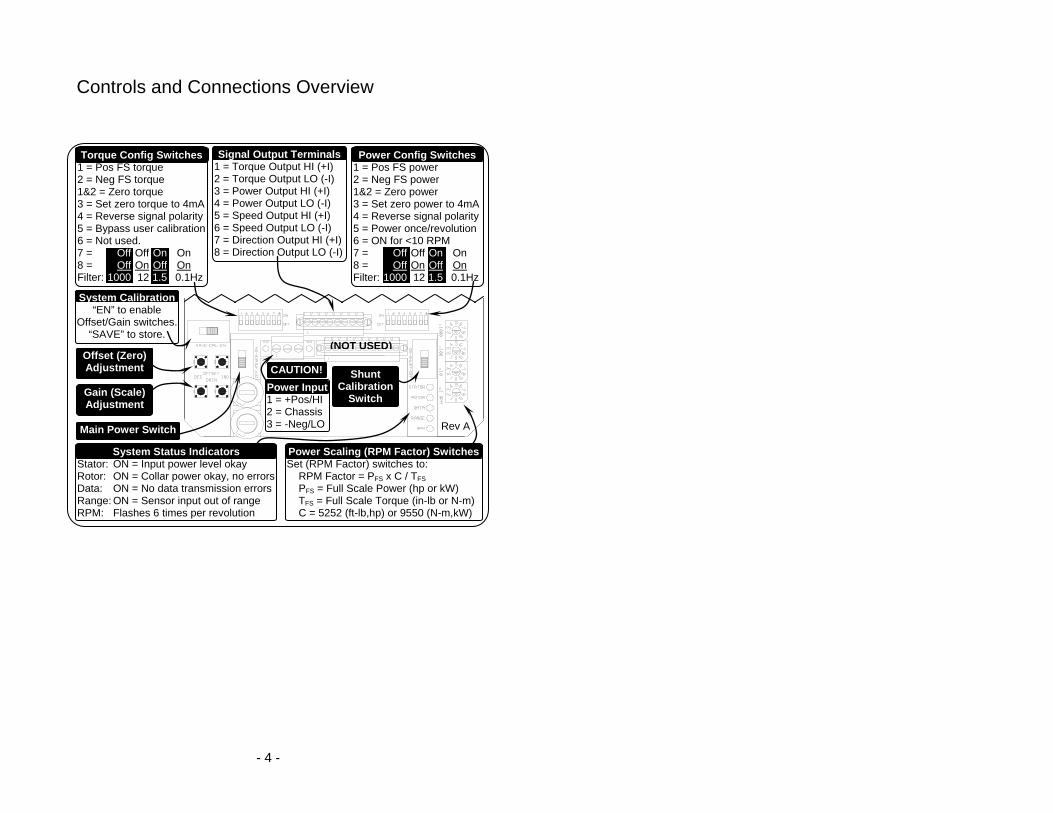
Power Config Switches 1 = Pos FS power 2 = Neg FS power 1&2 = Zero power 3 = Set zero power to 4mA 4 = Reverse signal polarity 5 = Power once/revolution 6 = ON for <10 RPM 7 = Off Off On On 8 = Off On Off On Filter: 1000 12 1.5 0.1Hz
Torque Config Switches 1 = Pos FS torque 2 = Neg FS torque 1&2 = Zero torque 3 = Set zero torque to 4mA 4 = Reverse signal polarity 5 = Bypass user calibration 6 = Not used. 7 = Off Off On On 8 = Off On Off On Filter: 1000 12 1.5 0.1Hz
System Calibration “EN” to enable
Offset/Gain switches. “SAVE” to store.
Gain (Scale) Adjustment
System Status Indicators Stator: ON = Input power level okay Rotor: ON = Collar power okay, no errors Data: ON = No data transmission errors Range: ON = Sensor input out of range RPM: Flashes 6 times per revolution
(NOT USED)
Signal Output Terminals 1 = Torque Output HI (+I) 2 = Torque Output LO (-I) 3 = Power Output HI (+I) 4 = Power Output LO (-I) 5 = Speed Output HI (+I) 6 = Speed Output LO (-I) 7 = Direction Output HI (+I) 8 = Direction Output LO (-I)
Power Scaling (RPM Factor) Switches Set (RPM Factor) switches to: RPM Factor = PFS x C / TFS PFS = Full Scale Power (hp or kW) TFS = Full Scale Torque (in-lb or N-m) C = 5252 (ft-lb,hp) or 9550 (N-m,kW)
Main Power Switch
Offset (Zero) Adjustment
Shunt Calibration
Switch
CAUTION!
Power Input 1 = +Pos/HI 2 = Chassis 3 = -Neg/LO
Rev A

- 5 -
Controls and Connections Power Input The Master Control Unit operates on 11-16 VDC (standard) or 115VAC or 230VAC (optional). Power connections are made via a removable three-position screw terminal block as shown below.
WARNING: Supply voltage (up to 230VAC) is live in the Master Control Unit even when the Main Power switch is off! Use caution when accessing internal controls.
Figure 2 - Power Input Controls and Connections
Main Power Switch
Fuses One fuse is connected to high side power, one fuse is connected to low side power.
Power Input Connector Block
DC Power AC Power Terminal 1: +Pos High Terminal 2: Chassis Gnd Chassis Gnd Terminal 3: -Neg Low
115VAC/230VAC Switch (only available with VAC Option)
Slide to the left for 115VAC power. Slide to the right for 230VAC power.

- 6 -
Torque Output Signal The 4-20mA torque output signal is accessed from a removable eight-position screw terminal block on the upper-most board in the Master Control Unit. Torque signal calibration controls, including gain and offset adjustments, are described below.
Figure 3 - Torque Output Controls and Connections
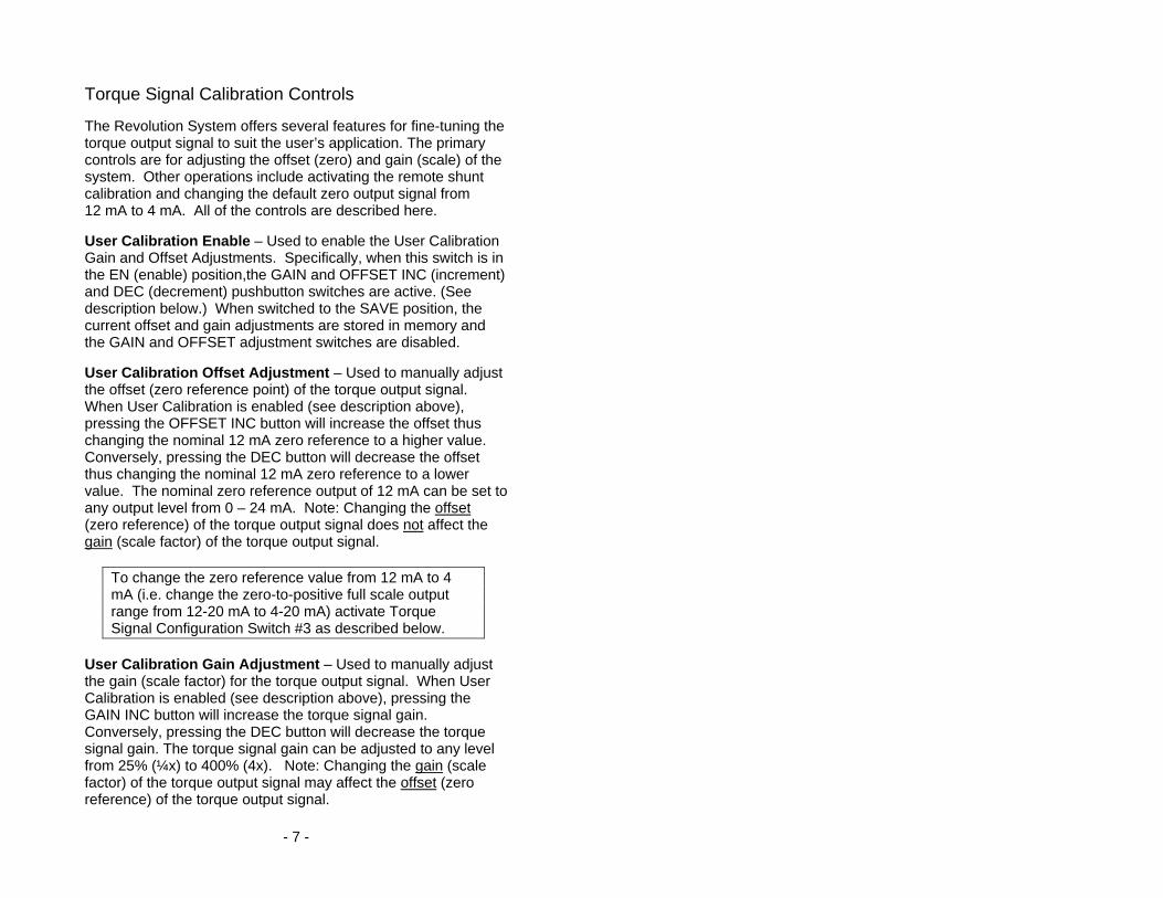
Torque Signal Configuration Switches Used to set data signal options, e.g. activating low pass filter or reversing signal polarity. See details below.
Torque Signal Output Terminals Terminal 1 = Shaft Torque Output Current Loop (+I) Terminal 2 = Shaft Torque Output Current Loop Return (Common)
User Calibration Enable Switch ENabled (right) position: Calibration is enabled (gain and offset adjustments
are active and will affect the torque output signal) SAVE (left) position: Calibration is saved (gain and offset settings are stored
in memory and adjustment switches are disabled)
User Calibration Offset Adjustment (Zero Reference Adjustment)
Push DEC switch to decrease torque output signal offset. Push INC switch to increase torque output signal offset.
User Calibration Gain Adjustment (Scale Adjustment)
Push DEC switch to decrease torque output signal gain. Push INC switch to increase torque output signal gain.
Remote Shunt Calibration Switch Used to place a precision “shunt” resistor across one arm of the full-bridge strain gage sensor simulating 50% full scale torque.
- 7 -
Torque Signal Calibration Controls The Revolution System offers several features for fine-tuning the torque output signal to suit the user’s application. The primary controls are for adjusting the offset (zero) and gain (scale) of the system. Other operations include activating the remote shunt calibration and changing the default zero output signal from 12 mA to 4 mA. All of the controls are described here. User Calibration Enable – Used to enable the User Calibration Gain and Offset Adjustments. Specifically, when this switch is in the EN (enable) position,the GAIN and OFFSET INC (increment) and DEC (decrement) pushbutton switches are active. (See description below.) When switched to the SAVE position, the current offset and gain adjustments are stored in memory and the GAIN and OFFSET adjustment switches are disabled. User Calibration Offset Adjustment – Used to manually adjust the offset (zero reference point) of the torque output signal. When User Calibration is enabled (see description above), pressing the OFFSET INC button will increase the offset thus changing the nominal 12 mA zero reference to a higher value. Conversely, pressing the DEC button will decrease the offset thus changing the nominal 12 mA zero reference to a lower value. The nominal zero reference output of 12 mA can be set to any output level from 0 – 24 mA. Note: Changing the offset (zero reference) of the torque output signal does not affect the gain (scale factor) of the torque output signal.
To change the zero reference value from 12 mA to 4 mA (i.e. change the zero-to-positive full scale output range from 12-20 mA to 4-20 mA) activate Torque Signal Configuration Switch #3 as described below.
User Calibration Gain Adjustment – Used to manually adjust the gain (scale factor) for the torque output signal. When User Calibration is enabled (see description above), pressing the GAIN INC button will increase the torque signal gain. Conversely, pressing the DEC button will decrease the torque signal gain. The torque signal gain can be adjusted to any level from 25% (¼x) to 400% (4x). Note: Changing the gain (scale factor) of the torque output signal may affect the offset (zero reference) of the torque output signal.

- 8 -
Remote Shunt Calibration Switch – Used to verify system operation without directly accessing the strain gage. When switched to the ON position, a fixed precision resistance (inside the Transmitter Module) is applied across one arm of the strain gage bridge simulating strain that produces a torque signal output corresponding to 50% of Full Scale in the positive direction at factory default settings. In the OFF position, the resistance is removed from the sensor. Note: The System Status Indicator light flashes (and the internal “Rotor” light flashes) when the Remote Shunt is applied. Torque Signal Configuration Switches – Used to set specific torque signal parameters as listed here. The ON position for each switch is upwards (towards the Power Ring). Switch Function when switch is ON:
1 Simulates a positive full scale torque input signal from the transmitter (nominally generates 20 mA output)
2 Simulates a negative full scale torque input signal from the transmitter (nominally generates 4 mA output)
1&2 Simulates a zero input signal from the transmitter (nominally generates a 12 mA output)
3 Full Scale Torque Output Range: 4-20mA with dipswitch #3 ON (up) 12±8mA with dipswitch #3 OFF (down)
3 Reverses the polarity of the torque signal 4 System bypasses the user calibration settings (i.e.
manual gain and offset adjustments are ignored) 5 (Not used)
To restore the factory offset and gain settings: a) Slide SAVE-CAL-ENable switch to “EN” position b) Activate dipswitch #5 of Torque Signal
Configuration panel, “Bypass User Calibration” c) Slide SAVE-CAL-ENable switch to “SAVE” position d) Deactivate dipswitch #5 of Torque Signal
Configuration panel. (See Torque Configuration Switch details below.)
- 9 -
7&8 Used to set frequency response of torque signal (i.e. select cut-off frequency for low pass filter) as follows:
Switch 7 Switch 8 Cut-off Frequency Off Off 1000 Hz Off On 12 Hz On Off 1.5 Hz On On 0.1 Hz
Figure 4 - Torque Signal Configuration Switches
Torque Signal Configuration Switches

- 10 -
Power Output Signal The 4-20 mA shaft power output signal is accessed from a removable eight-position screw terminal block on the upper-most board in the Master Control Unit. Power signal scaling and configuration switches are described below.
Figure 5 - Power Output Controls and Connections
Power Signal Configuration Switches Used to set data signal options, e.g. activating low pass filter or reversing signal polarity. See table below for details.
Power Signal Output Terminals Terminal 3 = Power Output Current Loop (+I) Terminal 4 = Power Output Current Loop Return (Common)
Power Scaling (RPM Factor) Switches Use these rotary switches to set the scale factor relating the torque signal to the shaft power signal according to the equation:
PFS x Constant / TFS = RPM Factor. See details below and in Set Up Procedure.

- 11 -
Power Signal Calibration Controls The Revolution System offers several features for fine-tuning the power output signal including adjusting the full scale value and selecting the frequency response. The power scaling and configuration controls are described here.
The only offset (zero reference) adjustment for the power signal is via switch #3 in the Power Signal Configuration Switch panel. (See details below). If Power Configuration switch #3 is not activated a power output signal of 12 mA will always indicate zero power and zero power will always correspond to zero torque and/or zero RPM.
Power Scaling (RPM Factor) Switches – Used to set the full scale range for the power output signal (as described in the Set Up Procedure). There are four rotary switches corresponding to thousands (x1000), hundreds (x100), tens (x10) and units (x1). The switches are set by using a small screwdriver to turn the dial indicator to the desired digit and then cycling system power. Note: System must be turned OFF then ON (using Main Power Switch) to register new RPM factor switch settings! For example, if the calculated RPM Factor is 1490 then the switches would be set as follows: x1000 - position 1 x100 - position 4 x10 - position 9 x1 - position 0 IMPORTANT: Power supply to the TorqueTrak Revolution must be cycled Off, then back On, to make effective any changes to the RPM Factor switch setting.
Note: The power signal gain (sensitivity) is dependent upon and proportional to the torque gain.
Power Signal Configuration Switches – Used to set specific power signal parameters as listed here. Note: The ON position for each switch is upwards (towards the Power Ring).

- 12 -
Switch Function when switch is ON: 1 Generates positive full scale power output signal (20mA) 2 Generates negative full scale power output signal (4 mA) 1&2 Generates zero power output signal (12 mA) 3 Full Scale Power Output Range:
4-20mA with dipswitch #3 ON (up) 12±8mA with dipswitch #3 OFF (down)
4 Reverses the polarity of the power signal 5 Updates power output signal once per shaft revolution 6 Normally OFF. ON for very low speed shafts (<10 RPM) 7&8 Used to set frequency response of power signal (i.e. select cut-
off frequency for low pass filter) as follows: Switch 7 Switch 8 Cut-off Frequency Off Off 1000 Hz Off On 12 Hz On Off 1.5 Hz On On 0.1 Hz
Figure 6 - Power Signal Scaling and Configuration Switches
Power Scaling (RPM Factor) Switches
Power Signal Configuration Switches

- 13 -
When switch #3 is activated the output signal at zero power changes from 12 mA to 4 mA and simultaneously the signal gain is doubled. When Switch #5 is OFF, the power output signal is calculated and updated 6 times per shaft revolution (i.e. whenever the RPM sensor is triggered). When Switch #5 is ON, the power output signal is calculated and updated only once per shaft revolution thereby averaging the power data over a complete revolution. Switch #6 is used when the shaft speed is very low (less than 10 RPM). When Switch #6 is ON the system adds a delay between the time the RPM sensor is triggered and the time the power output signal is allowed to indicate zero power. This feature prevents a slowly rotating shaft from erroneously generating a zero power data signal.

- 14 -
Speed (RPM) and Direction Output Signals The 5 or 19mA speed (RPM) and direction output signals are accessed from a removable eight-position screw terminal block on the upper-most board in the Master Control Unit as described below.
Figure 7 - Speed and Direction Output Connections The speed (RPM) output signal is a pulse train that is nominally 5 mA or 19 mA (depending on shaft direction) which pulses to the alternate current level at the following rate: RPM FPULSE = ------------ 10 FPULSE = Frequency of the pulse train in Hertz RPM = Shaft revolutions/minute
Direction Signal Output Terminals Terminal 7 = Direction of Rotation Output Current Loop (+I) Terminal 8 = Direction of Rotation Output Current Loop Return (Common)
Speed (RPM) Signal Output Terminals Terminal 5 = Speed Output Current Loop (+I) Terminal 6 = Speed Output Current Loop Return (Common)

- 15 -
When viewed from the front of the Master Control Unit with the coil board on the Rotating Collar in view a clockwise rotation produces a speed signal that is nominally 19 mA with 5 mA pulses. Conversely a counterclockwise rotation produces a speed signal that is nominally 5 mA with 19 mA pulses. Six magnets in the Rotating Collar trigger the pickup sensor in the Mounting Block on top of the Master Control Unit to generate the speed signal. The direction signal is a simple binary indicator, 5 mA when the shaft rotates in one direction and 19 mA when it rotates in the other direction. Clockwise Shaft Rotation: Direction signal: 19 mA, constant Speed signal: 19 mA, pulsing to 5 mA at the rate of 6 pulses
per revolution Counterclockwise Shaft Rotation: Direction signal: 5 mA, constant Speed signal: 5 mA, pulsing to 19 mA at the rate of 6 pulses
per revolution NOTE: The maximum load resistance of any one of the TorqueTrak Revolution output current loops is 500 ohms. This means the system can drive the 4-20 mA output signal into resistances of 0 to 500 ohms. To calculate the distance the signal can travel, add the input resistance of the device you plan to “drive” plus the resistance of the wire length. As long as the total resistance is less than 500 ohms, the TorqueTrak Revolution output signal will drive the device.

- 16 -
System Status Indicator Lights There is one Main System Status Indicator light located outside the Master Control Unit at the base of the Power Ring and five secondary system status indicator lights inside the unit. See Appendix C: Error Codes & Troubleshooting for indicator details.
Figure 8 - System Status Indicators
Secondary System Status Indicators Stator (Green) = On solid if input power level is in range Rotor (Green) = On solid if collar power is in range and no data errors Data (Green) = On solid if no data transmission errors Range (Red) = Off if sensor input signal is within range RPM (Green) = At slow shaft speeds used to verify operation of RPM
sensor. LED flashes as magnets trigger pickup sensor.
Main System Status Indicator
Red light is on solid if no system errors are present
- 17 -
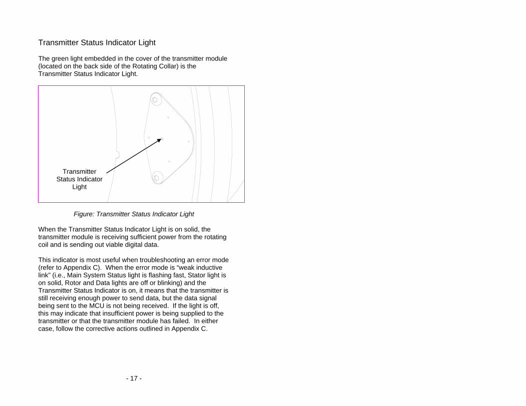
Transmitter Status Indicator Light The green light embedded in the cover of the transmitter module (located on the back side of the Rotating Collar) is the Transmitter Status Indicator Light.
Figure: Transmitter Status Indicator Light
When the Transmitter Status Indicator Light is on solid, the transmitter module is receiving sufficient power from the rotating coil and is sending out viable digital data. This indicator is most useful when troubleshooting an error mode (refer to Appendix C). When the error mode is “weak inductive link” (i.e., Main System Status light is flashing fast, Stator light is on solid, Rotor and Data lights are off or blinking) and the Transmitter Status Indicator is on, it means that the transmitter is still receiving enough power to send data, but the data signal being sent to the MCU is not being received. If the light is off, this may indicate that insufficient power is being supplied to the transmitter or that the transmitter module has failed. In either case, follow the corrective actions outlined in Appendix C.
Transmitter Status Indicator
Light

- 18 -
Installation Procedure 1. If not already installed, attach strain gage(s) (or other
sensors) to shaft being measured. (See Appendix D: Strain Gage Application for simplified instructions.)
2. For 4-piece Rotating Collars and Power Rings, pre-assemble
half-sections using hardware and instructions provided. Make sure 4-piece collar sections are assembled in the correct order, otherwise speed and power sensing features will not function properly.
3. Apply anti-seize compound (provided) to threads of collar
bolts. Assemble collar on shaft adjacent to gage with ribbon cable from collar leading towards gage. (Refer to Figure 1 on page 3 or Figure 10 on page 20.) Install opposing collar bolts from opposite directions to maintain balance. Tighten alternate bolts evenly until gap between collar halves is .100” (2.5mm) at all junctions. (See Figure 9 below.)
CAUTION: Before proceeding make sure bolts are tight enough to prevent loosening while rotating but not so tight that the boards attached to the Rotating Collar are interfering with each other.
Figure 9 - Correct Collar Gap Spacing
jumper wire
0.100” (2.5 mm)
0.020” (0.5 mm)

- 19 -
4. After collar is bolted on the shaft, place jumper wires
(provided) in the screw terminal connectors at each collar junction as shown in Figure 9 and tighten securely.
5. Assemble one half of Power Ring to Master Control Unit
using hardware provided. Position Master Control Unit with half-ring around shaft and assemble second half of Power Ring.
6. Securely mount Master Control Unit to machine or mounting
plate (not provided) so that the Rotating Collar is centered within the Power Ring. (Refer to Figure 1 on page 3 or Figure 10 on page 20.) For larger systems, use the Support Brackets provided to stabilize and support the Power Ring with additional braces.
7. Remove cover from Master Control Unit. Install cable clamps
or conduit connectors (not provided) in holes in bottom of box. Route data signal wires from process control or recording equipment through clamps or connectors then connect to corresponding screw terminals (black connector) inside unit. Note: Wiring holes must be sealed accordingly to prevent contamination in the enclosure.
8. Route electrical power wires through clamps or connectors
then connect to corresponding electrical power terminals (green connector) inside unit.
NOTE: Steps 9-11 outline verification of system operation. A star bridge has been pre-wired to the Revolution transmitter for this purpose. Completing the verification will greatly reduce troubleshooting effort if a system error exists.
9. Slide main power switch to ON. After 10 seconds, verify that Main System Status light is on solid, indicating successful data transmission. If Main System Status light is flashing, see Appendix C: Error Codes & Troubleshooting.
10. Connect an amp meter (not provided) to the Torque Signal
Output Terminals (1 & 2) inside MCU. Measure the Torque Signal (mA). Reading should be approximately 12 mA.
- 20 -
11. Slide Remote Shunt switch to ON (Main System Status light will flash). Measure Torque Signal current. Reading should be approximately 16 mA. Slide Remote Shunt switch to OFF position. (Main System Status light will return to on solid.) Slide main power switch to OFF.
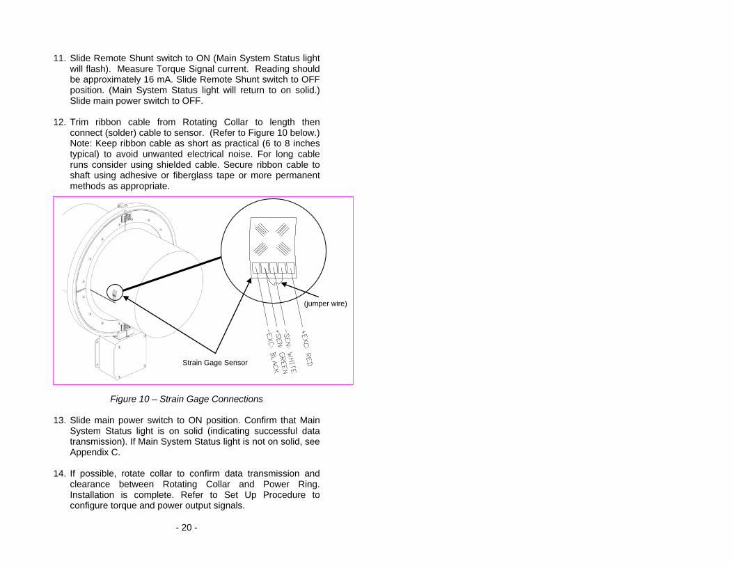
12. Trim ribbon cable from Rotating Collar to length then
connect (solder) cable to sensor. (Refer to Figure 10 below.) Note: Keep ribbon cable as short as practical (6 to 8 inches typical) to avoid unwanted electrical noise. For long cable runs consider using shielded cable. Secure ribbon cable to shaft using adhesive or fiberglass tape or more permanent methods as appropriate.
Figure 10 – Strain Gage Connections 13. Slide main power switch to ON position. Confirm that Main
System Status light is on solid (indicating successful data transmission). If Main System Status light is not on solid, see Appendix C.
14. If possible, rotate collar to confirm data transmission and
clearance between Rotating Collar and Power Ring. Installation is complete. Refer to Set Up Procedure to configure torque and power output signals.
(jumper wire)
Strain Gage Sensor

- 21 -
Set Up Procedure The power output signal from the Revolution System is generated using the measured torque value (from the strain gage) and the measured shaft speed (RPM). System setup requires four basic steps: Step 1: Calculate the nominal full scale torque range Step 2: Select an appropriate full scale power level Step 3: Calculate the corresponding RPM Factor Step 4: Set the RPM Factor switches For initial set up, it is recommended that all of the Torque and Power Configuration switches be set to the OFF position. Step 1: Calculate the nominal full scale torque (TFull Scale) range as described in Appendix B. The simplified torque equation is duplicated here for convenience:
Step 2: Select “Power Full Scale” (PFull Scale), The value you choose to correspond to the full scale power output, 20mA.
(377.60)(Do
3) = TFull Scale (ft-lb) with Do in inches
(GF)
or (Do
3) = TFull Scale (N-m) with Do in mm (GF)(32.02)
where: Do = Shaft Outer Diameter (inches or mm) TFull Scale = Full Scale Torque (ft-lb or N-m) GF = Gage Factor (from gage package)
- 22 -
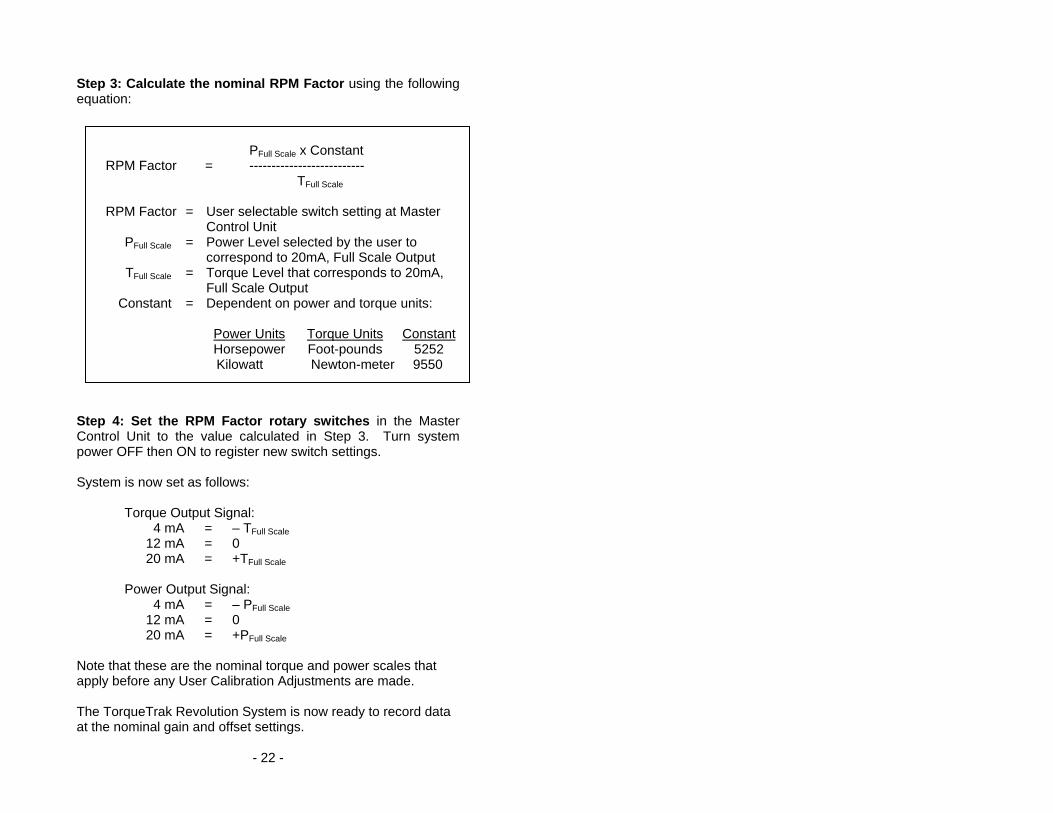
Step 3: Calculate the nominal RPM Factor using the following equation:
Step 4: Set the RPM Factor rotary switches in the Master Control Unit to the value calculated in Step 3. Turn system power OFF then ON to register new switch settings. System is now set as follows:
Torque Output Signal: 4 mA = – TFull Scale 12 mA = 0 20 mA = +TFull Scale Power Output Signal: 4 mA = – PFull Scale 12 mA = 0 20 mA = +PFull Scale
Note that these are the nominal torque and power scales that apply before any User Calibration Adjustments are made. The TorqueTrak Revolution System is now ready to record data at the nominal gain and offset settings.
PFull Scale x Constant
RPM Factor = -------------------------- TFull Scale
RPM Factor = User selectable switch setting at Master
Control Unit PFull Scale = Power Level selected by the user to
correspond to 20mA, Full Scale Output TFull Scale = Torque Level that corresponds to 20mA,
Full Scale Output Constant = Dependent on power and torque units: Power Units Torque Units Constant Horsepower Foot-pounds 5252 Kilowatt Newton-meter 9550

- 23 -
Example: Given a solid steel shaft with
Do (shaft diameter, measured) = 2.5 inches GF (gage factor from gage package) = 2.045 STrans (Transmitter sensitivity) = 1 mV/V PFull Scale (estimated max power level) = 800 hp
(377.60)(2.50 in)3 TFull Scale = ------------------------- = 2,885 ft-lb
(2.045)
800 hp x 5252 RPM Factor = ------------------------- = 1456 (switch setting)
2,885 ft-lb In this example the torque and power output signals can be interpreted as follows:
Torque Output Signal: 4 mA = –2,885 ft-lb 12 mA = 0 ft-lb 20 mA = +2,885 ft-lb Power Output Signal: 4 mA = – 800 hp 12 mA = 0 hp 20 mA = +800 hp
Conversion Chart for Common Units
Power Torque SI: Kilowatt (kW) Newton–meter (N-m) 1 kW = 1.341 hp 1 N-m = 0.737 ft-lb English: Horsepower (hp) Foot-pound (ft-lb) 1 hp = 0.746 kW 1 ft-lb = 1.356 N-m

- 24 -
Advanced User Calibration Adjustments The torque offset and gain levels can be manually adjusted via the User Calibration Offset and Gain Adjustments described in the Calibration and Controls section of the manual. This can be done in one of two ways: Deadweight Method: The most precise method for determining Sensitivity of the system is a true mechanical calibration, sometimes called a Deadweight Test, where a known torque (a known force/weight on a known moment-arm) is applied to the shaft. Example: 100 pounds weight on a 1-foot moment-arm equals 100 foot-pounds “known Torque-Input.” Observe the Current-Output of the TorqueTrak Revolution system. Sensitivity of the entire system is equal to the Torque-Input per Current-Output. Take two or more points of reference using different known Torque-Input values as confirmation of the ”Sensitivity” value determined. Shunt Calibration Method: The easiest and next best way to conduct a calibration is by enabling the Shunt Calibration Switch. (Alternatively, precision resistors can be connected in parallel with one arm of the bridge to simulate a torque load.) When the Remote Shunt is turned ON, a precision resistor internal to the transmitter is activated to simulate a precise strain value equivalent to 50% of Full Scale in the positive direction. With the gage installed and wired to the instrument, the torque offset value is adjusted until the desired output signal or display value is reached (see procedure described on page 7). Next, enable the Shunt Calibration Switch and adjust the torque gain value until the desired output signal or display value is reached. Repeat the offset and gain adjustments (alternating from Shunt Calibration Switch ON and OFF) until readings are stable and repeatable. NOTE: The maximum gain adjustment possible using the Remote Shunt is 3X with dipswitch #3 off.
IMPORTANT: The full scale power range (PFS ) and power scale (RPM Factor) must correspond to the actual full scale torque, not simply the nominal full scale torque. In other words, if the full scale torque range is manually adjusted then the full scale power range must be recalculated.
- 25 -
Appendix A: Revolution Specifications Transmitter Module (mounted inside Rotating Collar) Sensor Input: Full (4-arm) Wheatstone Bridge strain gage
(120-1000 ohms; 350-ohms standard) Bridge Input: Approx. 2.5 VDC, regulated Sensor Range: ±500 microstrain (Torque or Bending)
(Full Bridge, 4 Active Arms) ±769 microstrain (Tension or Compression) (Full Bridge, 2.6 Active Arms)
(Corresponding transmitter sensitivity is 1mV/V. Microstrain values based on nominal gage factor of 2.0. See data sheet from gage manufacturer for actual gage factor.) Temp Coefficient: Gain: ≤ 0.005% FS/°C (50ppm/°C) +20° to +70°C ≤ 0.010% FS/°C (100ppm/°C) -40° to +85°C Zero: ≤ 0.005% FS/°C (50ppm/°C) +20° to +70°C ≤ 0.010% FS/°C (100ppm/°C) -40° to +85°C Non-linearity: ≤ 0.05%FS Sensor Connection: 4-conductor cable Size: Diameter: 1.5 inches (38 mm) Width: 0.75 inches (19 mm) Rotating Collar Material: Cast nylon Size: (see appropriate drawing) http://www.binsfeld.com/index.php/tech_info/TTR_dimensioned_drawings/
Master Control Unit and Power Ring Output Signals: Four independent current output signals:
1. Torque: 4-20 mA nominal, scalable (usable from 0-24 mA)
2. Shaft power: 4-20 mA nominal, scalable (usable from 0-24 mA)
3. Speed (RPM): Pulse Indicator, 5 or 19 mA 4. Direction: Binary Indicator, 5 or 19 mA

- 26 -
Input Power: 11-16 VDC standard; 2A max, 0.5A nominal (115VAC or 230VAC option available) Output Connections: Screw Terminals Size and Weight - Master Control Unit: 6 x 6 x 4 inches (15 cm x 15 cm x 10 cm) 6 lbs (2.72 kg) Size and Weight - Collar: Outer Diameter: (see appropriate drawing) http://www.binsfeld.com/index.php/tech_info/TTR_dimensioned_drawings/ Collar Width: 1.25 inch (31.75 mm) Weight: Dependent on shaft diameter Overall System Resolution: 14 bits (±full scale = 16384 points) Torque Noise Level: ≤ 0.10% RMS FS Frequency Response: Switch selectable: (Torque and Power) 1000 Hz, 12 Hz, 1.5 Hz or 0.1 Hz
(-3dB frequency (typical))
Delay: 1 msec, typical (at 1000 Hz setting) Slew Rate: 33mA/msec, typical (at 1000 Hz setting) Sample Rate: 4800 Hz Operating Temperature: -40° to +85°C 0% to 90% relative humidity,
noncondensing

- 27 -
Appendix B: Torque Calibration Calculations The equations in this Appendix define the full scale torque range of the Revolution system based on shaft parameters (e.g. shaft diameter), strain gage parameters (e.g. gage factor) and the Revolution transmitter gain setting (preset at the factory and documented below). For easy calculations, use the calculator found at our website. http://www.binsfeld.com/calculators/ttrevo_range/ Calculate Nominal Full Scale Torque, TFull Scale (ft-lb) To calculate the nominal full scale torque, ±TFull Scale (ft-lb) that corresponds to a nominal system output of 12 ± 8 mA
For all other shafts (e.g. hollow) use the more general equation:
Legend of Terms
Di Shaft Inner Diameter (in) (zero for solid shafts) Do Shaft Outer Diameter (in) E Modulus of Elasticity (30 x 106 PSI for steel) GF Gage Factor (specified on strain gage package)
STrans Transmitter sensitivity (mV/V) (not user configurable); Typical is 1 mV/V for ±500 microstrain range
N Number of Active Gages (4 for torque) TFullScale Full Scale Torque (ft-lb) ν Poisson’s Ratio (0.30 for steel)
(377.60)(Do
3) = TFull Scale (ft-lb) [solid shaft]
(GF)
(STrans)(π)(E)(4)(Do4-Di
4) = TFull Scale (ft-lb) (GF)(N)(16,000)(1+ν)(Do)(12)

- 28 -
(STrans)(π)(E)(4)(Do4 – Di
4) = TFull Scale(N-m) (GF)(N)(16 x 106)(1+ν)(Do)
For metric applications with Do and Di in millimeters and TFull Scale in Newton-meters the general equation is: Where E = 206.8 x 10³ N/mm2.
Example: Given a solid steel shaft with
Do (shaft diameter, measured) = 2.5 inches GF (gage factor from gage package) = 2.045 STrans (transmitter sensitivity) = 1 mV/V PFull Scale (estimated max power level) = 800 hp
(377.60)(2.50 in)3 TFull Scale = ------------------------- = 2,885 ft-lb
(2.045) In this example the torque output signal can be interpreted as follows:
4 mA = – 2,885 ft-lb 12 mA = 0 ft-lb 20 mA =+ 2,885 ft-lb
Note that this is the nominal torque scale that applies before any User Calibration Adjustments are made

- 29 -
Appendix C: Error Codes & Troubleshooting Indicator Condition Main Status (Red LED)
On solid * No errors Fast flash a) Remote Shunt Switch is on
b) One or more system errors present
Stator (Green LED) On solid * Electrical power (voltage) to system is in range Fast flash Electrical power (voltage) to system is too high Slow flash Electrical power (voltage) to system is too low
Rotor (Green LED)
On solid * Rotating Collar electrical power is in range and no data errors present Fast flash Rotating Collar electrical power is too high Slow flash Rotating Collar electrical power is too low Off Data transmission errors, or no rotor power
Data (Green LED)
On solid * Data received without errors Off Data transmission errors, or no rotor power
(A flickering Data light indicates intermittent data transmission.) Range (Red LED)
On solid Sensor input to transmitter is over range Off * Sensor input to transmitter is within range if
stator, rotor and data LED’s are on solid (The Range indicator may flash or flicker with a dynamic over-range condition. When the Range light is on the torque and therefore power signals are in error.) RPM (Green LED)
On* Speed sensor triggering properly Off Speed sensor not triggering
(Flashes 6 times per shaft revolution so will appear on solid or flashing depending on shaft speed.) Transmitter Status Indicator (Green LED)
On solid * Sufficient power being received from rotating coil Off Zero or insufficient power from rotating coil or
the transmitter has failed

- 30 -
In error mode, output signals = 24 mA. Fast flash rate = 4 Hz; Slow flash rate = 2 Hz * Indicates normal (error free) mode Common Error Modes and Suggested Corrective Actions If an error is present, the Main System Status Indicator will flash and the system will display an error code briefly (another 10-15 seconds) before the startup cycle repeats. Below are the most common error modes and potential corrective actions. Error Mode: Power supply voltage to system is incorrect
Symptom: Main System Status flashing fast, Stator flashing Action: 1. Supply correct voltage to the MCU
Error Mode: Weak inductive link
Symptom: Main System Status flashing fast, Stator on solid, Rotor flashing slow, Data off or flickering,
Transmitter statur indicator off. Action: 1. Verify voltage is about 35 mVAC across the Mounting Blocks on top of the MCU
2. Make certain the Power Ring is not shorted to the MCU enclosure by water or other conductive material
3. Remove any surrounding metal other than the shaft within 4 inches (10 cm) of the Power Ring
4. Clean mating surfaces of the Power Ring and tighten all mounting screws
5. Verify that the Rotating Coil voltage is about 120 mVAC (probe the two terminal dots on the outer surface of the coil boards attached to the Rotating Collar)
6. Check alignment of the Rotating Collar within the Power Ring: their midlines should be aligned
7. Make certain Rotating Collar jumper wires are securely tightened and the screw terminal connectors are not damaged
Error Mode: Strain gage problem
Symptom: Main System Status flashing fast, Range on solid Action: 1. Verify excitation voltage to gage is 2.5 VDC
2. Check solder connections and wiring to gage 3. Balance the gage to reduce offset or apply a
new gage

- 31 -
Using the BS900 Bridge Simulator for Troubleshooting A BS900 Bridge Simulator is shipped with each Revolution system inside the Master Control Unit. The Bridge Simulator is very useful for isolating the cause of a suspect data signal as it "simulates" a properly installed strain gage. By disconnecting the actual strain gage and temporarily connecting the Bridge Simulator to the ribbon cable from the Rotating Collar the user can quickly determine if the suspect output signal is a function of a faulty strain gage installation (including solder connections) or is due to a malfunctioning Revolution system. Connect the BS900 as follows: Ribbon Cable from BS900 Bridge
Rotating Collar Simulator Pin RED + EXC GREEN + SENS WHITE – SENS BLACK – EXC The Bridge Simulator has a three-position slide switch to simulate zero load, 20% of negative nominal full scale and 20% of positive nominal full scale. Shown below are the approximate torque data output signals you should get with the Revolution system at original factory settings. “Negative” Center “Positive” Torque Output: 10.4 mA 12 mA 13.6 mA
IMPORTANT: If you get accurate and repeatable output signals using the Bridge Simulator, which is normally the case, then the Revolution system is operating properly and you should focus your troubleshooting attention on the strain gage installation including possible wiring errors. Also you can use the Star Bridge (shipped installed on transmitter/rotating collar) to verify that excitation voltage (2.5VDC) is present.

- 32 -
Appendix D: Strain Gage Application (Also refer to instruction bulletin B-127-12 provided with GAK-2-200 Strain Gage Application Kit from Vishay Measurements Group, Inc., Raleigh, NC, 919-365-3800, www.measurementsgroup.com.) PREPARING THE SURFACE
1. A 3-inch square area will be used for gaging. Scrape off any paint or other coatings and inspect shaft for oil residue. If necessary, use a degreasing solution or isopropyl alcohol to remove.
2. Rough sand the gaging area with 220 grit paper. Finish
the sanding procedure by wetting the gaging area with M-Prep Conditioner A and the wetted surface with 400 grit paper provided. Rinse by squirting with M-Prep Conditioner A. Wipe the area dry with tissue taking care to wipe in only one direction. Each time you wipe use a clean area of the tissue to eliminate contamination.
3. Rinse shaft this time by squirting with M-Prep
Neutralizer 5A. Wipe the gaging area dry with a clean tissue, wiping in only one direction and using clean area of tissue with each wipe. Do not allow any solution to dry on the surface as this may leave a contaminating film which can reduce bonding. Surface is now prepared for bonding.
MARKING THE SHAFT FOR GAGE ALIGNMENT
4. The gage needs to be perpendicular to the shaft axis. In general, this can be accomplished by eye since misalignment of less than 4 degrees will not generate significant errors. For higher precision, we recommend two methods for marking the shaft: a) Use a machinist square and permanent marker or
scribe for perpendicular and parallel lines; or b) Cut a strip of graph paper greater than the
circumference of the shaft. Tape it to the shaft while lining up the edges. Mark desired gage position with a scribe or permanent marker.
- 33 -
PREPARING THE GAGE FOR MOUNTING 5. Using tweezers, remove one gage from its package.
Using the plastic gage box as a clean surface, place the gage on it, bonding side down. Take a 6” piece of PCT-2M Mylar Tape and place it on the gage and terminal, centered. Slowly lift the tape at a shallow angle. You should now have the gage attached to the tape.
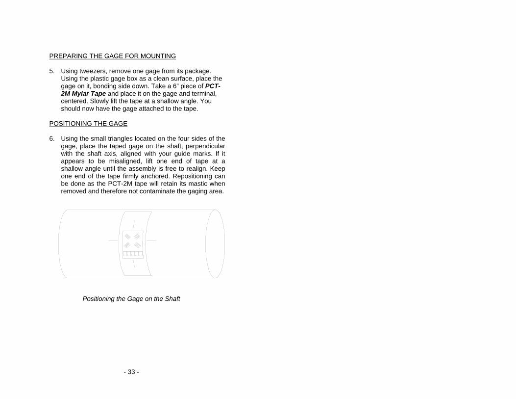
POSITIONING THE GAGE 6. Using the small triangles located on the four sides of the
gage, place the taped gage on the shaft, perpendicular with the shaft axis, aligned with your guide marks. If it appears to be misaligned, lift one end of tape at a shallow angle until the assembly is free to realign. Keep one end of the tape firmly anchored. Repositioning can be done as the PCT-2M tape will retain its mastic when removed and therefore not contaminate the gaging area.
Positioning the Gage on the Shaft
- 34 -
7. Gage should now be positioned. Once again, lift the gage end of the tape at a shallow angle to the surface until the gage is free of the surface. Continue pulling the tape until you are approximately 1/8” – 1/4” beyond gage. Turn the leading edge of the tape under and press it down, leaving the bonding surface of the gage exposed.
8. Apply a very thin, uniform coat of M-Bond 200-Catalyst
to the bonding surface of the gage. This will accelerate the bonding when glue is applied. Very little catalyst is needed. Lift the brush cap out and wipe excess on lip of bottle. Use just enough catalyst to wet gage surface. Before proceeding, allow catalyst to dry at least one minute under normal ambient conditions of + 75°F and 30-65% relative humidity.
NOTE: The next three steps must be completed in sequence within 3 – 5 seconds. Read through instructions before proceeding so there will be no delays.
Have Ready: M-Bond (Cyanoacrylate) Adhesive 2” – 5” piece of teflon tape Tissues MOUNTING THE GAGE
9. Lift the leading edge of the tape and apply a thin bead of adhesive at the gage end where the tape meets the shaft. Adhesive should be of thin consistency to allow even spreading. Extend the line of glue outside the gage installation area.
10. Holding the tape taut, slowly and firmly press with a
single wiping stroke over the tape using a teflon strip (to protect your thumb from the adhesive) and a tissue (to absorb excess adhesive that squeezes out from under the tape). This will bring the gage back down over the alignment marks on the gaging area. This forces the glue line to move up and across the gage area. A very thin, uniform layer of adhesive is desired for optimum bond performance.

- 35 -
11. Immediately, using your thumb, apply firm pressure to the taped gage by rolling your thumb over the gage area. Hold the pressure for at least one minute. In low humidity conditions (below 30%) or if ambient temperature is below + 70° F, pressure application time may have to be extended to several minutes.
12. Leave the mylar tape on an additional five minutes to
allow total drying then slowly peel the tape back directly over itself, holding it close to the shaft while peeling. This will prevent damage to the gages. It is not necessary to remove the tape immediately after installation. It offers some protection for the gaged surface and may be left until wiring the gage.
WIRING THE GAGE
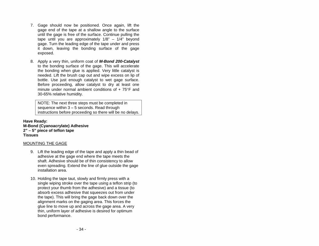
13. Tin each solder pad with a solder dot. (It is helpful to polish the solder tabs, e.g. with a fiberglass scratch brush or mild abrasive, before soldering.) Trim and tin the ends of the 4-conductor ribbon wire. Solder the lead wires to the gage by placing the tinned lead onto the solder dot and pressing it down with the hot soldering iron. Note: For single-stamp torque gages, a short jumper is required between solder pads 2 and 4 as shown in the diagram on the next page
14. Use the rosin solvent to clean excess solder rosin from
the gage after wiring. Brush the gage pads with the solvent and dab with a clean tissue.
15. Paint the gage area (including the solder pads) with M-
Coat A polyurethane and allow to air dry 15 minutes. This protects the gage from moisture and dirt. To further protect the gage, apply M-Coat J protective coating for protection against moisture, fluids and mechanical damage.
- 36 -
- 37 -
Warranty and Service Information LIMITED WARRANTY Please record the date of purchase with the instrument serial numbers: Date of Purchase: Master Control Unit: Rotating Transmitter: Binsfeld Engineering Inc. warrants that its products will be free from defective material and workmanship for a period of one year from the date of delivery to the original purchaser and that its products will conform to specifications and standards published by Binsfeld Engineering Inc. Upon evaluation by Binsfeld Engineering Inc., any product found to be defective will be replaced or repaired at the sole discretion of Binsfeld Engineering Inc. Our warranty is limited to the foregoing, and does not apply to fuses, paint, or any equipment, which in Binsfeld Engineering’s sole opinion has been subject to misuse, alteration, or abnormal conditions of operation or handling. This warranty is exclusive and in lieu of all other warranties, expressed or implied, including but not limited to any implied warranty of merchantability or fitness for a particular purpose or use. Binsfeld Engineering Inc. will not be liable for any special, indirect, incidental or consequential damages or loss, whether in contract, tort, or otherwise. NOTE (USA only): Some states do not allow limitation of implied warranties, or the exclusion of incidental or consequential damages so the above limitations or exclusions may not apply to you. This warranty gives you specific legal rights and you may have other rights which vary from state to state. For service please contact Binsfeld Engineering Incorporated: Phone: +1-231-334-4383 Fax: +1-231-334-4903 E-mail: [email protected]