toroidal current transformers - davidsonsalesshop.com catalog.pdf · toroidal current...
TRANSCRIPT

W.I.C.C. Ltd 119 MULLER RD PO Box 252 WASHINGTON IL 61571 (309)-444-4125 FAX (309)-444-3313
PAGE No 1-0
Toroidal Current Transformers... Traditional, window type current transformer for measuring 50-400HZ currents of 10A to 15000A with secondaries of .1A, 1A, and 5A (special secondary currents are available). W.I.C.C. manufactures toroidal designs having inside diameters of up to 8.00”. Many models are available as U.L. Recognized devices. Typical applications include UPS systems, transfer switches, motor-generator sets, commercial sub-metering, and motor-drive systems.
REV 18DEC00
Model A…. ................................. 1-2 Model AA ..............................….. 1-4 Model AX ..............................….. 1-6 Model C ... ..............................….1-8 Model CX ..............................….1-10 Model D ………………………….1-12 Model DE ………………………..1-14 Model DX ………………………..1-16 Model E ………………………….1-18 Model F ………………………….1-20 Model K ………………………….1-22 Model L595 ……………………...1-24 Model MW ……………………….1-26 Model MWX ……………………..1-28 Model N ………………………….1-30 Model ND ………………………..1-32 Model NDX ……………………...1-34 Model 546 ……………………….1-38
Model 591 ……………………….1-40 Model 594 ……………………….1-42 Model 599 ……………………….1-44 Model 617 ……………………….1-46 Model 635 ……………………….1-48 Model 636 ……………………….1-50 Model 652 ……………………….1-52 Model 652F ……………………..1-54 Model 653 ……………………….1-56 Model 653F ……………………..1-58 Model 653X ……………………..1-60 Model 653FX ……………………1-62 Model 1306 ……………………...1-64 Model 2559 ……………………...1-66 Model 2560 ……………………...1-68 Model 2562 ……………………...1-70 Model 2638 ……………………...1-72 Model 2743 ……………………...1-74
Table of Contents (alphabetical)

PAGE No 1-1
W.I.C.C. Ltd 119 MULLER RD PO Box 252 WASHINGTON IL 61571 (309)-444-4125 FAX (309)-444-3313
0.38" (Model 2638) …….......…...1-72 0.53" (Model 1306) ……………...1-64 0.75" (Model L595) ……….……..1-24 1.10" (Model 546) ……………….1-38 1.10" (Model 635) ……………….1-48 1.10" (Model 636) ……………….1-50 1.10" (Model 2559) ……………..1-66 1.50" (Model D) ……....………….1-12 1.50" (Model DE) ………………..1-14 1.50" (Model DX) ………………..1-16 1.56" (Model 2560) ……………...1-68 2.06" (Model 2562) ……………...1-70 2.06" (Model 2743) ……………...1-74 2.25" (Model A) ........................... 1-2 2.25" (Model AA) ...................….. 1-4 2.25" (Model AX) ...................….. 1-6 2.25" (Model 591) ……………….1-40 2.50" (Model 652) ……………….1-52
2.50" (Model 652F) ……………..1-54 2.50" (Model 653) ……………….1-56 2.50" (Model 653F) ……………..1-58 2.50" (Model 653X) ……………..1-60 2.50" (Model 653FX) ……………1-62 2.60" (Model 599) ……………….1-44 2.75" (Model 594) ……………….1-42 2.88" (Model C) .......................….1-8 2.88" (Model CX) ...................….1-10 3.50" (Model MW) ……………....1-26 3.50" (Model MWX) ……………..1-28 4.25" (Model N) ………………….1-30 4.25" (Model ND) ………………..1-32 4.25" (Model NDX) ……………...1-34 5.00" (Model E) ………………….1-18 6.25" (Model K) ………………….1-22 6.50" (Model 617) ……………….1-46 8.00" (Model F) ………………….1-20
Table of Contents (by window I.D.)
REV 18DEC00
W.I.C.C. Ltd 119 MULLER RD PO Box 252 WASHINGTON IL 61571 (309)-444-4125 FAX (309)-444-3313
PAGE No 1-2
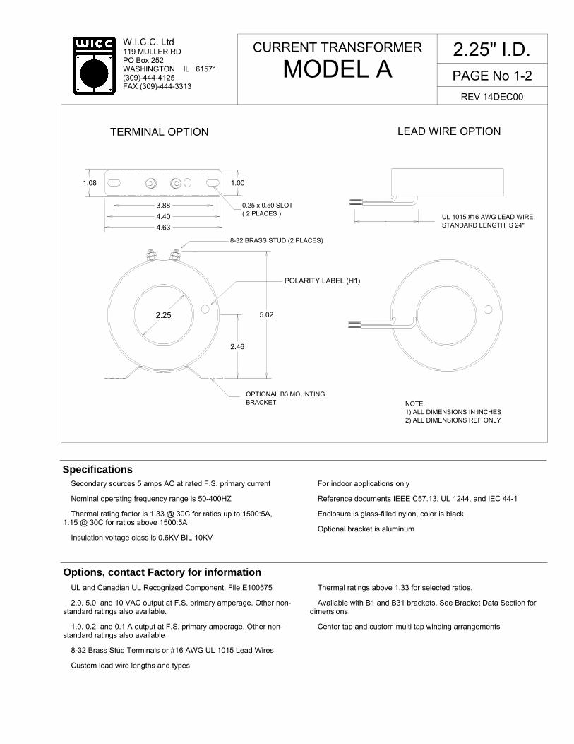
� Secondary sources 5 amps AC at rated F.S. primary current
� Nominal operating frequency range is 50-400HZ
� Thermal rating factor is 1.33 @ 30C for ratios up to 1500:5A, 1.15 @ 30C for ratios above 1500:5A
� Insulation voltage class is 0.6KV BIL 10KV
� For indoor applications only
� Reference documents IEEE C57.13, UL 1244, and IEC 44-1
� Enclosure is glass-filled nylon, color is black
� Optional bracket is aluminum
Specifications
� UL and Canadian UL Recognized Component. File E100575
� 2.0, 5.0, and 10 VAC output at F.S. primary amperage. Other non-standard ratings also available.
� 1.0, 0.2, and 0.1 A output at F.S. primary amperage. Other non-standard ratings also available
� 8-32 Brass Stud Terminals or #16 AWG UL 1015 Lead Wires
� Custom lead wire lengths and types
� Thermal ratings above 1.33 for selected ratios.
� Available with B1 and B31 brackets. See Bracket Data Section for dimensions.
� Center tap and custom multi tap winding arrangements
Options, contact Factory for information
CURRENT TRANSFORMER
MODEL A
2.25" I.D.
REV 14DEC00
1.08 1.00
3.88
4.40
4.63
LEAD WIRE OPTION
UL 1015 #16 AWG LEAD WIRE,STANDARD LENGTH IS 24"
5.022.25
NOTE:1) ALL DIMENSIONS IN INCHES2) ALL DIMENSIONS REF ONLY
TERMINAL OPTION
0.25 x 0.50 SLOT( 2 PLACES )
OPTIONAL B3 MOUNTINGBRACKET
8-32 BRASS STUD (2 PLACES)
2.46
POLARITY LABEL (H1)

PAGE No 1-3
W.I.C.C. Ltd 119 MULLER RD PO Box 252 WASHINGTON IL 61571 (309)-444-4125 FAX (309)-444-3313
TYPICAL EXCITATION CURVE for WICC MODEL A at 60HZ
10-3
10-2
10-1
100
101
102
IND
UC
ED
VO
LT
AG
E (
volt)
10-4
10-3
10-2
10-1
100
101
EXCITING CURRENT (amp)
W.I.C.C. PART NUMBER *
RATIO
ACCURACY @ 60HZ, pf = 0.95
± % BURDEN (VA)
NOMINAL WINDING RESISTANCE (ohm)
A-200-00-xxx A-250-00-xxx A-300-00-xxx A-400-00-xxx A-500-00-xxx A-600-00-xxx A-750-00-xxx A-800-00-xxx
A-1000-00-xxx A-1200-00-xxx A-1500-00-xxx
200:5A 250:5A 300:5A 400:5A 500:5A 600:5A 750:5A 800:5A 1000:5A 1200:5A 1500:5A
1.0 1.0 1.0 1.0 1.0 1.0 1.0 1.0 1.0 1.0 1.0
2.0 3.0 4.5 4.0 6.5 7.5 12.5 12.5 17.5 22 30
0.02 0.05 0.06 0.11 0.13 0.15 0.18 0.20 0.25 0.30 0.39
CURRENT TRANSFORMER
MODEL A
2.25" I.D.
REV 14DEC00
400:
5A
500:
5A
750:
5A
1200
:5A
1000
:5A
* "xxx" describes termination: "T" FOR BRASS STUDS, "Lyyy" FOR LEAD WIRES (Where "yyy" is the lead length in inches. For example, "L24" represents 24 inch long lead wires.)
1500
:5A
W.I.C.C. Ltd 119 MULLER RD PO Box 252 WASHINGTON IL 61571 (309)-444-4125 FAX (309)-444-3313
PAGE No 1-4
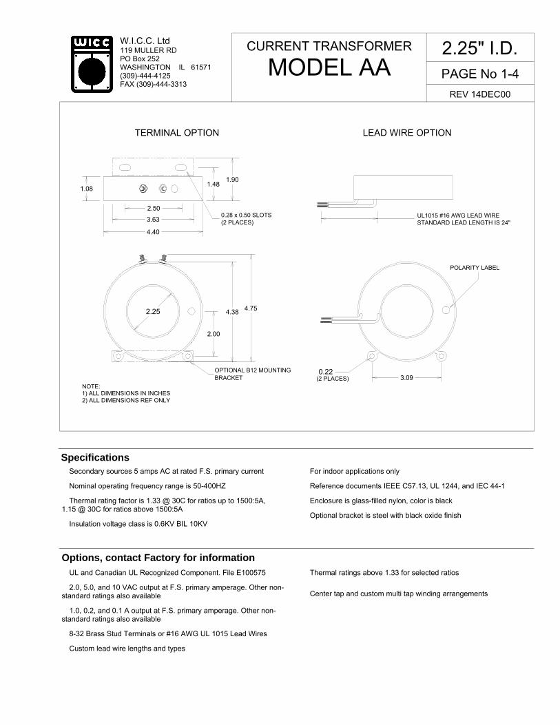
� Secondary sources 5 amps AC at rated F.S. primary current
� Nominal operating frequency range is 50-400HZ
� Thermal rating factor is 1.33 @ 30C for ratios up to 1500:5A, 1.15 @ 30C for ratios above 1500:5A
� Insulation voltage class is 0.6KV BIL 10KV
� For indoor applications only
� Reference documents IEEE C57.13, UL 1244, and IEC 44-1
� Enclosure is glass-filled nylon, color is black
� Optional bracket is steel with black oxide finish
Specifications
� UL and Canadian UL Recognized Component. File E100575
� 2.0, 5.0, and 10 VAC output at F.S. primary amperage. Other non-standard ratings also available
� 1.0, 0.2, and 0.1 A output at F.S. primary amperage. Other non-standard ratings also available
� 8-32 Brass Stud Terminals or #16 AWG UL 1015 Lead Wires
� Custom lead wire lengths and types
� Thermal ratings above 1.33 for selected ratios
� Center tap and custom multi tap winding arrangements
Options, contact Factory for information
CURRENT TRANSFORMER
MODEL AA
2.25" I.D.
REV 14DEC00
0.28 x 0.50 SLOTS(2 PLACES)
NOTE:
2) ALL DIMENSIONS REF ONLY
UL1015 #16 AWG LEAD WIRESTANDARD LEAD LENGTH IS 24"
(2 PLACES)0.22
TERMINAL OPTION LEAD WIRE OPTION
1.081.48
1.90
2.00
4.38 4.752.25
1) ALL DIMENSIONS IN INCHES
2.50
3.63
4.40
OPTIONAL B12 MOUNTINGBRACKET
POLARITY LABEL
3.09

PAGE No 1-5
W.I.C.C. Ltd 119 MULLER RD PO Box 252 WASHINGTON IL 61571 (309)-444-4125 FAX (309)-444-3313
10-4
10-3
10-2
10-1
100
101
EXCITATION CURRENT (amp)
TYPICAL EXCITATION CURVE FOR WICC MODEL AA at 60HZ
10-3
10-2
10-1
100
101
102
IND
UC
ED
VO
LT
AG
E (
volt)
W.I.C.C. PART NUMBER *
RATIO
ACCURACY @ 60HZ, pf = 0.95
± % BURDEN (VA)
NOMINAL WINDING RESISTANCE (ohm)
AA-200-00-xxx AA-250-00-xxx AA-300-00-xxx AA-400-00-xxx AA-500-00-xxx AA-600-00-xxx AA-750-00-xxx AA-800-00-xxx AA-1000-00-xxx AA-1200-00-xxx AA-1500-00-xxx
200:5A 250:5A 300:5A 400:5A 500:5A 600:5A 750:5A 800:5A 1000:5A 1200:5A 1500:5A
1.0 1.0 1.0 1.0 1.0 1.0 1.0 1.0 1.0 1.0 1.0
2.0 3.0 4.5 4.0 6.5 7.5 12.5 12.5 17.5 22 30
0.02 0.05 0.06 0.11 0.13 0.15 0.18 0.20 0.25 0.30 0.39
CURRENT TRANSFORMER
MODEL AA
2.25" I.D.
REV 14DEC00
400:
5A
500:
5A
750:
5A
1200
:5A
1000
:5A
* "xxx" describes termination: "T" FOR BRASS STUDS, "Lyyy" FOR LEAD WIRES (Where "yyy" is the lead length in inches. For example, "L24" represents 24 inch long lead wires.)
1500
:5A

W.I.C.C. Ltd 119 MULLER RD PO Box 252 WASHINGTON IL 61571 (309)-444-4125 FAX (309)-444-3313
PAGE No 1-6
� Secondary sources 5 amps AC at rated F.S. primary current
� Nominal operating frequency range is 50-400HZ
� Thermal rating factor is 1.33 @ 30C for all ratios
� Insulation voltage class is 0.6KV BIL 10KV � For indoor applications only
� Reference documents IEEE C57.13, UL 1244, and IEC 44-1
� Enclosure is glass-filled nylon, color is black
� Optional bracket is aluminum
Specifications
� UL and Canadian UL Recognized Component. File E100575
� 2.0, 5.0, and 10 VAC output at F.S. primary amperage. Other non-standard ratings also available.
� 1.0, 0.2, and 0.1 A output at F.S. primary amperage. Other non-standard ratings also available
� 8-32 Brass Stud Terminals or #18 AWG UL 1015 Lead Wires
� Custom lead wire lengths and types
� Thermal ratings above 1.33 for selected ratios.
� Available with B1 and B31 brackets. See Bracket Data Section for dimensions.
� Center tap and custom multi tap winding arrangements
Options, contact Factory for information
CURRENT TRANSFORMER
MODEL AX
2.25" I.D.
REV 14DEC00
1.08 1.00
3.88
4.40
4.63
LEAD WIRE OPTION
UL 1015 #16 AWG LEAD WIRE,STANDARD LENGTH IS 24"
5.022.25
NOTE:1) ALL DIMENSIONS IN INCHES2) ALL DIMENSIONS REF ONLY
TERMINAL OPTION
0.25 x 0.50 SLOT( 2 PLACES )
OPTIONAL B3 MOUNTINGBRACKET
8-32 BRASS STUD (2 PLACES)
2.46
POLARITY LABEL (H1)

PAGE No 1-7
W.I.C.C. Ltd 119 MULLER RD PO Box 252 WASHINGTON IL 61571 (309)-444-4125 FAX (309)-444-3313
10-3
10-2
10-1
100
101
102
IND
UC
ED
VO
LT
AG
E (
volt)
TYPICAL EXCITATION CURVE for WICC MODEL AX at 60HZ
10-4
10-3
10-2
10-1
100
101
EXCITING CURRENT (amp)
W.I.C.C. PART NUMBER *
RATIO
ACCURACY @ 60HZ, pf = 0.95
± % BURDEN (VA)
NOMINAL WINDING RESISTANCE (ohm)
AX-050-00-xxx AX-100-00-xxx AX-150-00-xxx AX-600-00-xxx
50:5A 100:5A 150:5A 600:5A
5.0 2.0 1.5 1.0
1.0 2.0 2.0 30
0.01 0.02 0.04 0.14
CURRENT TRANSFORMER
MODEL AX
2.25" I.D.
REV 14DEC00
50:5
A 10
0:5A
150:
5A
* "xxx" describes termination: "T" FOR BRASS STUDS, "Lyyy" FOR LEAD WIRES (Where "yyy" is the lead length in inches. For example, "L24" represents 24 inch long lead wires.)
600:
5A

W.I.C.C. Ltd 119 MULLER RD PO Box 252 WASHINGTON IL 61571 (309)-444-4125 FAX (309)-444-3313
PAGE No 1-8
� Secondary sources 5 amps AC at rated F.S. primary current
� Nominal operating frequency range is 50-400HZ
� Thermal rating factor is 1.33 @ 30C for ratios up to 1600:5A, 1.15 @ 30C for ratios above 1600:5A
� Insulation voltage class is 0.6KV BIL 10KV
� For indoor applications only � Reference documents IEEE C57.13, UL1244, and IEC 44-1
� Enclosure is glass-filled nylon, color is black
� Optional plate is XX phenolic, optional bracket is aluminum
Specifications
� UL and Canadian UL Recognized Component. File E100575
� 2.0, 5.0, and 10 VAC output at F.S. primary amperage. Other non-standard ratings also available.
� 1, 0.2, and 0.1 A output at F.S. primary amperage. Other non-standard ratings also available
� 8-32 Brass Stud Terminals or #16 AWG UL 1015 Lead Wires
� Custom lead wire lengths and types
� Thermal ratings above 1.33 for selected ratios.
� Available with B1 and B31 brackets. See Bracket Data Section for dimensions.
� Available with B54 bracket when ratio is above 500:5A. See Bracket Data Section for dimensions.
� Center tap and custom multi tap winding arrangements
Options, contact Factory for information
CURRENT TRANSFORMER
MODEL C 2.88" I.D.
REV 14DEC00
2.88
OPTIONAL P8 PLATEOPTIONAL B3 BRACKET
TERMINAL OPTION LEAD WIRE OPTION
2.95
6.03
POLARITY LABEL (H1)
3.88
4.63
5.35
8-32 BRASS STUD (2 PLACES)
0.25 x 0.50 SLOT(2 PLACES)
1.00
1.13
UL 1015 #16 AWG LEAD WIRE,STANDARD LENGTH IS 24"
Ø0.25(4 PLACES)
1.31
5.38
4.38
4.38 5.38
2). ALL DIMENSIONS REF ONLY1). ALL DIMENSIONS IN INCHESNOTES

PAGE No 1-9
W.I.C.C. Ltd 119 MULLER RD PO Box 252 WASHINGTON IL 61571 (309)-444-4125 FAX (309)-444-3313
10-4
10-3
10-2
10-1
100
101
EXCITING CURRENT (amp)
10-3
10-2
10-1
100
101
102
IND
UC
ED
VO
LT
AG
E (
volt)
TYPICAL EXCITATION CURVE for WICC MODEL C at 60HZ
W.I.C.C. PART NUMBER *
RATIO
ACCURACY @ 60HZ, pf = 0.95
± % BURDEN (VA)
NOMINAL WINDING RESISTANCE (ohm)
C-200-00-xxx C-250-00-xxx C-300-00-xxx C-400-00-xxx C-500-00-xxx C-600-00-xxx C-800-00-xxx
C-1000-00-xxx C-1200-00-xxx C-1500-00-xxx C-1600-00-xxx C-1800-00-xxx C-2000-00-xxx
200:5A 250:5A 300:5A 400:5A 500:5A 600:5A 800:5A 1000:5A 1200:5A 1500:5A 1600:5A 1800:5A 2000:5A
1.5 1.0 1.0 1.0 1.0 1.0 1.0 1.0 1.0 1.0 1.0 1.0 1.0
2.0 2.0 3.0 7.0 10 12 20 25 30 35 30 30 35
0.06 0.08 0.09 0.12 0.14 0.15 0.20 0.25 0.30 0.40 0.43 0.50 0.60
CURRENT TRANSFORMER
MODEL C 2.88" I.D.
REV 14DEC00
200:
5A
300:
5A
400:
5A
500:
5A
800:
5A
1000
:5A
1500
:5A
2000
:5A
1200
:5A
* "xxx" describes termination: "T" FOR BRASS STUDS, "Lyyy" FOR LEAD WIRES (Where "yyy" is the lead length in inches. For example, "L24" represents 24 inch long lead wires.)

W.I.C.C. Ltd 119 MULLER RD PO Box 252 WASHINGTON IL 61571 (309)-444-4125 FAX (309)-444-3313
PAGE No 1-10
� Secondary sources 5 amps AC at rated F.S. primary current
� Nominal operating frequency range is 50-400HZ
� Thermal rating factor is 1.33 @ 30C for all ratios
� Insulation voltage class is 0.6KV BIL 10KV � For indoor applications only
� Reference documents IEEE C57.13, UL1244, and IEC 44-1
� Enclosure is glass-filled nylon, color is black
� Optional plate is XX phenolic, optional bracket is aluminum
Specifications
� UL and Canadian UL Recognized Component. File E100575
� 2.0, 5.0, and 10 VAC output at F.S. primary amperage. Other non-standard ratings also available.
� 1, 0.2, and 0.1 A output at F.S. primary amperage. Other non-standard ratings also available
� 8-32 Brass Stud Terminals or #16 AWG UL 1015 Lead Wires
� Custom lead wire lengths and types
� Thermal ratings above 1.33 for selected ratios.
� Available with B1 and B31 brackets. See Bracket Data Section for dimensions.
� Available with B54 bracket when ratio is above 500:5A. See Bracket Data Section for dimensions.
� Center tap and custom multi tap winding arrangements
Options, contact Factory for information
CURRENT TRANSFORMER
MODEL CX 2.88" I.D.
REV 14DEC00
2.88
OPTIONAL P8 PLATEOPTIONAL B3 BRACKET
TERMINAL OPTION LEAD WIRE OPTION
2.95
6.03
POLARITY LABEL (H1)
3.88
4.63
5.35
8-32 BRASS STUD (2 PLACES)
0.25 x 0.50 SLOT(2 PLACES)
1.00
1.13
UL 1015 #16 AWG LEAD WIRE,STANDARD LENGTH IS 24"
Ø0.25(4 PLACES)
1.31
5.38
4.38
4.38 5.38
2). ALL DIMENSIONS REF ONLY1). ALL DIMENSIONS IN INCHESNOTES
PAGE No 1-11
W.I.C.C. Ltd 119 MULLER RD PO Box 252 WASHINGTON IL 61571 (309)-444-4125 FAX (309)-444-3313
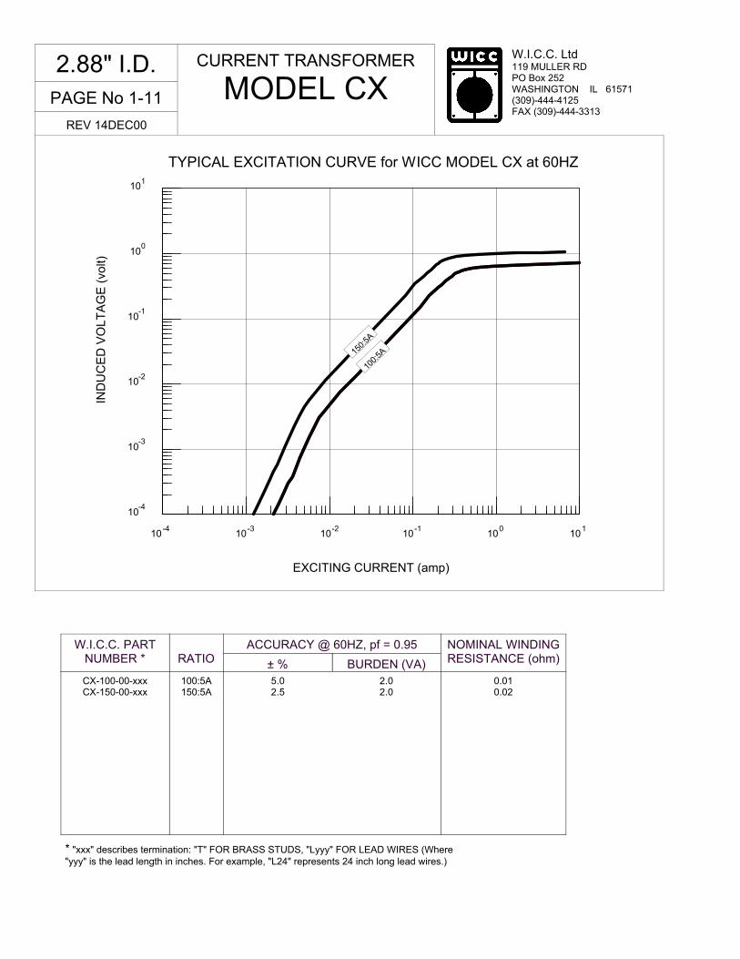
TYPICAL EXCITATION CURVE for WICC MODEL CX at 60HZ
10-4
10-3
10-2
10-1
100
101
IND
UC
ED
VO
LT
AG
E (
volt)
10-4
10-3
10-2
10-1
100
101
EXCITING CURRENT (amp)
W.I.C.C. PART NUMBER *
RATIO
ACCURACY @ 60HZ, pf = 0.95
± % BURDEN (VA)
NOMINAL WINDING RESISTANCE (ohm)
CX-100-00-xxx CX-150-00-xxx
100:5A 150:5A
5.0 2.5
2.0 2.0
0.01 0.02
CURRENT TRANSFORMER
MODEL CX 2.88" I.D.
REV 14DEC00
100:
5A 15
0:5A
* "xxx" describes termination: "T" FOR BRASS STUDS, "Lyyy" FOR LEAD WIRES (Where "yyy" is the lead length in inches. For example, "L24" represents 24 inch long lead wires.)

W.I.C.C. Ltd 119 MULLER RD PO Box 252 WASHINGTON IL 61571 (309)-444-4125 FAX (309)-444-3313
PAGE No 1-12
� Secondary sources 5 amps AC at rated F.S. primary current
� Nominal operating frequency range is 50-400HZ
� Thermal rating factor is 1.33 @ 30C for all ratios
� Insulation voltage class is 0.6KV BIL 10KV � For indoor applications only
� Reference documents IEEE C57.13, UL1244, and IEC 44-1
� Enclosure is glass-filled nylon, color is black
� Optional bracket is aluminum
Specifications
� UL and Canadian UL Recognized Component. File E100575
� 2.0, 5.0, and 10 VAC output at F.S. primary amperage. Other non-standard ratings also available.
� 1.0, 0.2, and 0.1 A output at F.S. primary amperage. Other non-standard ratings also available
� 8-32 Brass Stud Terminals or #16 AWG UL 1015 Lead Wires
� Custom lead wire lengths and types
� Thermal ratings above 1.33 for selected ratios.
� Available with B3 bracket. See Bracket Data Section for dimensions.
� Center tap and custom multi tap winding arrangements
Options, contact Factory for information
CURRENT TRANSFORMER
MODEL D
1.50" I.D.
REV 14DEC00
TERMINAL OPTION LEAD WIRE OPTION
1.38 1.00
4.63
3.88
3.58
3.75 4.16H1
X1
0.25 x 0.50 SLOTS( 2 PLACES )
UL1015 #16 AWG LEAD WIRESTANDARD LENGTH IS 24"
H1
X1
NOTE:1) ALL DIMENSIONS IN INCHES2) ALL DIMENSIONS REF ONLY
1.50
OPTIONAL B3 MOUNTINGBRACKET

PAGE No 1-13
W.I.C.C. Ltd 119 MULLER RD PO Box 252 WASHINGTON IL 61571 (309)-444-4125 FAX (309)-444-3313
10-4
10-3
10-2
100
101
10-1
EXCITING CURRENT (amp)
10-3
10-2
10-1
100
101
102
IND
UC
ED
VO
LT
AG
E (
volt)
TYPICAL EXCITATION CURVE for WICC MODEL D at 60HZ
W.I.C.C. PART NUMBER *
RATIO
ACCURACY @ 60HZ, pf = 0.95
± % BURDEN (VA)
NOMINAL WINDING RESISTANCE (ohm)
D-300-00-xxx D-400-00-xxx D-500-00-xxx D-750-00-xxx D-800-00-xxx
D-1000-00-xxx D-1200-00-xxx
300:5A 400:5A 500:5A 750:5A 800:5A 1000:5A 1200:5A
1.0 1.0 1.0 1.0 1.0 1.0 1.0
5.0 7.5 12.5 15
17.5 20 20
0.08 0.10 0.13 0.18 0.19 0.24 0.27
CURRENT TRANSFORMER
MODEL D
1.50" I.D.
REV 14DEC00
300:
5A
400:
5A
500:
5A
1000
:5A
750:
5A
* "xxx" describes termination: "T" FOR BRASS STUDS, "Lyyy" FOR LEAD WIRES (Where "yyy" is the lead length in inches. For example, "L24" represents 24 inch long lead wires.)

W.I.C.C. Ltd 119 MULLER RD PO Box 252 WASHINGTON IL 61571 (309)-444-4125 FAX (309)-444-3313
PAGE No 1-14
� Secondary sources 5 amps AC at rated F.S. primary current
� Nominal operating frequency range is 50-400HZ
� Thermal rating factor is 1.33 @ 30C for all ratios
� Insulation voltage class is 0.6KV BIL 10KV � For indoor applications only
� Reference documents IEEE C57.13, UL1244, and IEC 44-1
� Enclosure is glass-filled nylon, color is black
� Optional bracket is steel with black oxide finish
Specifications
� UL and Canadian UL Recognized Component. File E100575
� 2.0, 5.0, and 10 VAC output at F.S. primary amperage. Other non-standard ratings also available
� 1.0, 0.2, and 0.1 A output at F.S. primary amperage. Other non-standard ratings also available
� 8-32 Brass Stud Terminals or #16 AWG UL 1015 Lead Wires
� Custom lead wire lengths and types
� Thermal ratings above 1.33 for selected ratios
� Center tap and custom multi tap winding arrangements
Options, contact Factory for information
CURRENT TRANSFORMER
MODEL DE
1.50" I.D.
REV 14DEC00
NOTE:1) ALL DIMENSIONS IN INCHES2) ALL DIMENSIONS REF ONLY
H1
X1H1
X1
TERMINAL OPTION LEAD WIRE OPTION
1.38
2.69
3.58
0.28 x 0.50 SLOTS( 2 PLACES )
1.67
3.72 4.031.50
2.240.22
UL1015 #16 AWG LEAD WIRESTANDARD LENGTH IS 24"
OPTIONAL B22 MOUNTINGBRACKET
(2 PLACES)
3.45
1.772.18

PAGE No 1-15
W.I.C.C. Ltd 119 MULLER RD PO Box 252 WASHINGTON IL 61571 (309)-444-4125 FAX (309)-444-3313
10-3
10-2
10-1
100
101
102
IND
UC
ED
VO
LT
AG
E (
volt)
10-4
10-3
10-2
10-1
100
101
EXCITATION CURRENT (amp)
TYPICAL EXCITATION CURVES FOR WICC MODEL DE at 60HZ
W.I.C.C. PART NUMBER *
RATIO
ACCURACY @ 60HZ, pf = 0.95
± % BURDEN (VA)
NOMINAL WINDING RESISTANCE (ohm)
DE-300-00-xxx DE-400-00-xxx DE-500-00-xxx DE-750-00-xxx DE-800-00-xxx DE-1000-00-xxx DE-1200-00-xxx
300:5A 400:5A 500:5A 750:5A 800:5A 1000:5A 1200:5A
1.0 1.0 1.0 1.0 1.0 1.0 1.0
5.0 7.5 12.5 15
17.5 20 20
0.08 0.10 0.13 0.18 0.19 0.24 0.27
CURRENT TRANSFORMER
MODEL DE
1.50" I.D.
REV 14DEC00
300:
5A
400:
5A
500:
5A
1000
:5A
750:
5A
* "xxx" describes termination: "T" FOR BRASS STUDS, "Lyyy" FOR LEAD WIRES (Where "yyy" is the lead length in inches. For example, "L24" represents 24 inch long lead wires.)

W.I.C.C. Ltd 119 MULLER RD PO Box 252 WASHINGTON IL 61571 (309)-444-4125 FAX (309)-444-3313
PAGE No 1-16
� Secondary sources 5 amps AC at rated F.S. primary current
� Nominal operating frequency range is 50-400HZ
� Thermal rating factor is 1.33 @ 30C for all ratios
� Insulation voltage class is 0.6KV BIL 10KV � For indoor applications only
� Reference documents IEEE C57.13, UL1244, and IEC 44-1
� Enclosure is glass-filled nylon, color is black
� Optional bracket is aluminum
Specifications
� UL and Canadian UL Recognized Component. File E100575
� 2.0, 5.0, and 10 VAC output at F.S. primary amperage. Other non-standard ratings also available.
� 1.0, 0.2, and 0.1 A output at F.S. primary amperage. Other non-standard ratings also available
� 8-32 Brass Stud Terminals or #16 AWG UL 1015 Lead Wires
� Custom lead wire lengths and types
� Thermal ratings above 1.33 for selected ratios.
� Available with B3 bracket. See Bracket Data Section for dimensions.
� Center tap and custom multi tap winding arrangements
Options, contact Factory for information
CURRENT TRANSFORMER
MODEL DX
1.50" I.D.
REV 14DEC00
TERMINAL OPTION LEAD WIRE OPTION
1.38 1.00
4.63
3.88
3.58
3.75 4.16H1
X1
0.25 x 0.50 SLOTS( 2 PLACES )
UL1015 #16 AWG LEAD WIRESTANDARD LENGTH IS 24"
H1
X1
NOTE:1) ALL DIMENSIONS IN INCHES2) ALL DIMENSIONS REF ONLY
1.50
OPTIONAL B3 MOUNTINGBRACKET

PAGE No 1-17
W.I.C.C. Ltd 119 MULLER RD PO Box 252 WASHINGTON IL 61571 (309)-444-4125 FAX (309)-444-3313
10-4
10-3
10-2
10-1
100
EXCITING CURRENT (amp)
101
10-3
10-2
10-1
100
101
102
IND
UC
ED
VO
LT
AG
E (
volt)
TYPICAL EXCITATION CURVE for WICC MODEL DX at 60HZ
W.I.C.C. PART NUMBER *
RATIO
ACCURACY @ 60HZ, pf = 0.95
± % BURDEN (VA)
NOMINAL WINDING RESISTANCE (ohm)
DX-050-00-xxx DX-075-00-xxx DX-100-00-xxx DX-150-00-xxx DX-200-00-xxx DX-250-00-xxx
50:5A 75:5A
100:5A 150:5A 200:5A 250:5A
3.0 2.0 1.5 1.0 1.0 1.0
1.5 2.5 2.5 2.5 4.0 5.0
0.01 0.01 0.02 0.03 0.05 0.06
CURRENT TRANSFORMER
MODEL DX
1.50" I.D.
REV 14DEC00
50:5
A
* "xxx" describes termination: "T" FOR BRASS STUDS, "Lyyy" FOR LEAD WIRES (Where "yyy" is the lead length in inches. For example, "L24" represents 24 inch long lead wires.)
100:
5A
75:5
A 150:
5A
250:
5A

W.I.C.C. Ltd 119 MULLER RD PO Box 252 WASHINGTON IL 61571 (309)-444-4125 FAX (309)-444-3313
PAGE No 1-18
� Secondary sources 5 amps AC at rated F.S. primary current
� Nominal operating frequency range is 50-400HZ
� Thermal rating factor is 1.33 @ 30C for ratios up thru 5000:5A, 1.15 @ 30C for ratios above 5000:5A
� Insulation voltage class is 0.6KV BIL 10KV
� For indoor applications only
� Reference documents IEEE C57.13, UL1244, and IEC 44-1
� Enclosure is multi-layer tape buildup with heavy vinyl finish, color is black
� Optional bracket is aluminum, optional plate is XX phenolic
Specifications
� Medium voltage insulation classes (lead wires only, physical size increases)
� 1, 0.2, and 0.1 A output at F.S. primary amperage. Other non-standard ratings also available
� 8-32 Screw Terminals or #16 AWG UL 1015 Lead Wires
� Custom lead wire lengths and types
� Thermal ratings above 1.33 for selected ratios
� Center tap and custom multi tap winding arrangements
Options, contact Factory for information
CURRENT TRANSFORMER
MODEL E 5.00" I.D.
REV 14DEC00
5.00
0.751.50
6.75 8.50
6.75
8.50
4.11
8.20
5.75
7.00
7.44
1.75
UL 1015 #16 AWG LEAD WIRE,STANDARD LENGTH IS 24"
8-32 BRASS SCREW TERMINAL (2 PLACES)
SCREW CLAMPFOR SS BAND
OPTIONAL B1BRACKET
0.25 x 0.50 SLOT(2 PLACES)
Ø0.31(4 PLACES)
OPTIONAL P3MOUNTING
PLATE
SS BAND SECURES BRACKET(view of screw clamp band omitted for clarity)
TERMINAL OPTION LEAD WIRE OPTION
POLARITY LABEL(2 PLACES)
NOTES1). ALL DIMENSIONS IN INCHES2). ALL DIMENSIONS REF ONLY

PAGE No 1-19
W.I.C.C. Ltd 119 MULLER RD PO Box 252 WASHINGTON IL 61571 (309)-444-4125 FAX (309)-444-3313
10-4
10-3
10-2
10-1
100
101
EXCITING CURRENT (amp)
TYPICAL EXCITATION CURVE for WICC MODEL E at 60HZ
10-2
10-1
100
101
102
IND
UC
ED
VO
LT
AG
E (
volt)
103
* "xxx" describes termination: "T" FOR BRASS SCREW TERMINALS, "Lyyy" FOR LEAD WIRES (Where "yyy" is the lead length in inches. For example, "L24" represents 24 inch
W.I.C.C. PART NUMBER *
RATIO
ACCURACY @ 60HZ, pf = 0.95
± % BURDEN (VA)
NOMINAL WINDING RESISTANCE (ohm)
E-500-00-xxx E-600-00-xxx E-800-00-xxx
E-1000-00-xxx E-1200-00-xxx E-1500-00-xxx E-1600-00-xxx E-2000-00-xxx E-2500-00-xxx E-3000-00-xxx E-4000-00-xxx E-5000-00-xxx E-6000-00-xxx
500:5A 600:5A 800:5A 1000:5A 1200:5A 1500:5A 1600:5A 2000:5A 2500:5A 3000:5A 4000:5A 5000:5A 6000:5A
1.0 1.0 1.0 1.0 1.0 1.0 1.0 1.0 1.0 1.0 1.0 1.0 1.0
8.5 12.5 25 40 60 80 85 95
135 165 130 165 190
0.17 0.21 0.28 0.35 0.41 0.52 0.55 0.70 0.90 1.10 1.25 1.65 2.45
CURRENT TRANSFORMER
MODEL E 5.00" I.D.
REV 14DEC00
500:
5A
600:
5A
800:
5A
1000
:5A
1200
:5A
1500
:5A
2500
:5A
3000
:5A
2000
:5A
5000
:5A
6000
:5A

W.I.C.C. Ltd 119 MULLER RD PO Box 252 WASHINGTON IL 61571 (309)-444-4125 FAX (309)-444-3313
PAGE No 1-20
� Secondary sources 5 amps AC at rated F.S. primary current
� Nominal operating frequency range is 50-400HZ
� Thermal rating factor is 1.33 @ 30C for ratios up thru 7500:5A, 1.15 @ 30C for ratios above 7500:5A
� Insulation voltage class is 0.6KV BIL 10KV
� For indoor applications only
� Reference documents IEEE C57.13, UL1244, and IEC 44-1
� Enclosure is multi-layer tape buildup with heavy vinyl finish, color is black
� Optional bracket is aluminum, optional plate is XX phenolic
Specifications
� Medium voltage insulation classes (lead wires only, physical size increases)
� 1, 0.2, and 0.1 A output at F.S. primary amperage. Other non-standard ratings also available
� 8-32 Screw Terminals or #16 AWG UL 1015 Lead Wires
� Custom lead wire lengths and types
� Thermal ratings above 1.33 for selected ratios
� Center tap and custom multi tap winding arrangements
Options, contact Factory for information
CURRENT TRANSFORMER
MODEL F 8.00" I.D.
REV 14DEC00
TERMINAL OPTION LEAD WIRE OPTION
NOTES1). ALL DIMENSIONS IN INCHES2). ALL DIMENSIONS REF ONLY
8.00
5.757.00
0.75
1.13
SS BAND SECURES BRACKET(view of screw clamp band omitted for clarity)
0.25 X 0.50 SLOT(2 PLACES)
8-32 BRASS SCREWTERMINAL (2 PLACES)
POLARITY LABEL(2 PLACES)
OPTIONAL B1BRACKET SCREW CLAMP
FOR SS BAND
5.57
11.06
OPTIONALMOUNTING
PLATE
Ø0.50(4 PLACES)
8.50
10.00
8.50 10.00
1.50
UL 1015 #16 AWG LEAD WIRE,STANDARD LENGTH IS 24"
10.19

PAGE No 1-21
W.I.C.C. Ltd 119 MULLER RD PO Box 252 WASHINGTON IL 61571 (309)-444-4125 FAX (309)-444-3313
TYPICAL EXCITATION CURVE for WICC MODEL F at 60HZ
10-2
10-1
100
101
102
103
IND
UC
ED
VO
LT
AG
E (
volt)
10-4
10-3
10-2
10-1
100
101
EXCITING CURRENT (amp)
* "xxx" describes termination: "T" FOR BRASS SCREW TERMINALS, "Lyyy" FOR LEAD WIRES (Where "yyy" is the lead length in inches. For example, "L24" represents 24 inch
W.I.C.C. PART NUMBER *
RATIO
ACCURACY @ 60HZ, pf = 0.95
± % BURDEN (VA)
NOMINAL WINDING RESISTANCE (ohm)
F-500-00-xxx F-750-00-xxx F-1000-00-xxx F-1500-00-xxx F-2000-00-xxx F-3000-00-xxx F-5000-00-xxx F-8000-00-xxx
500:5A 750:5A 1000:5A 1500:5A 2000:5A 3000:5A 5000:5A 8000:5A
1.0 1.0 1.0 1.0 1.0 1.0 1.0 1.0
4.0 10 20 50 65 85
100 100
0.10 0.15 0.35 0.46 0.55 0.80 1.40 2.60
CURRENT TRANSFORMER
MODEL F 8.00" I.D.
REV 14DEC00
500:
5A
750:
5A
1000
:5A
1500
:5A
2000
:5A
3000
:5A
5000
:5A
8000
:5A

W.I.C.C. Ltd 119 MULLER RD PO Box 252 WASHINGTON IL 61571 (309)-444-4125 FAX (309)-444-3313
PAGE No 1-22
� Secondary sources 5 amps AC at rated F.S. primary current
� Nominal operating frequency range is 50-400HZ
� Thermal rating factor is 1.33 @ 30C for ratios up thru 4000:5A, 1.15 @ 30C for ratios above 4000:5A
� Insulation voltage class is 0.6KV BIL 10KV
� For indoor applications only
� Reference documents IEEE C57.13, UL1244, and IEC 44-1
� Enclosure is multi-layer tape buildup with heavy vinyl finish, color is black
� Optional bracket is aluminum, optional plate is XX phenolic
Specifications
� Medium voltage insulation classes (lead wires only, physical size increases)
� 1, 0.2, and 0.1 A output at F.S. primary amperage. Other non-standard ratings also available
� 8-32 Screw Terminals or #16 AWG UL 1015 Lead Wires
� Custom lead wire lengths and types
� Thermal ratings above 1.33 for selected ratios
� Center tap and custom multi tap winding arrangements
Options, contact Factory for information
CURRENT TRANSFORMER
MODEL K 6.25" I.D.
REV 14DEC00
0.75
5.75
7.00
8-32 BRASS SCREW TERMINAL (2 PLACES)
SCREW CLAMPFOR SS BAND
OPTIONAL B1BRACKET
0.25 x 0.50 SLOT(2 PLACES)
SS BAND SECURES BRACKET(view of screw clamp band omitted for clarity)
TERMINAL OPTION LEAD WIRE OPTION
POLARITY LABEL(2 PLACES)
NOTES1). ALL DIMENSIONS IN INCHES2). ALL DIMENSIONS REF ONLY
STANDARD LENGTH IS 24"UL 1015 #16 AWG LEAD WIRE,
6.75 8.50
6.75
8.50
Ø0.39(4 PLACES)
OPTIONAL P5MOUNTING
PLATE
6.25
4.56
9.06
1.55
1.31
8.25
PAGE No 1-23
W.I.C.C. Ltd 119 MULLER RD PO Box 252 WASHINGTON IL 61571 (309)-444-4125 FAX (309)-444-3313
10-2
10-1
100
101
102
103
IND
UC
ED
VO
LT
AG
E (
volt)
10-4
10-3
10-2
10-1
100
101
EXCITING CURRENT (amp)
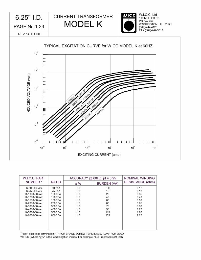
TYPICAL EXCITATION CURVE for WICC MODEL K at 60HZ
* "xxx" describes termination: "T" FOR BRASS SCREW TERMINALS, "Lyyy" FOR LEAD WIRES (Where "yyy" is the lead length in inches. For example, "L24" represents 24 inch
W.I.C.C. PART NUMBER *
RATIO
ACCURACY @ 60HZ, pf = 0.95
± % BURDEN (VA)
NOMINAL WINDING RESISTANCE (ohm)
K-500-00-xxx K-750-00-xxx
K-1000-00-xxx K-1200-00-xxx K-1500-00-xxx K-2000-00-xxx K-3000-00-xxx K-4000-00-xxx K-5000-00-xxx K-6000-00-xxx
500:5A 750:5A 1000:5A 1200:5A 1500:5A 2000:5A 3000:5A 4000:5A 5000:5A 6000:5A
1.0 1.0 1.0 1.0 1.0 1.0 1.0 1.0 1.0 1.0
6.0 15 25 40 65 85 75 90
115 135
0.12 0.18 0.35 0.40 0.50 0.65 0.90 1.20 1.80 2.20
CURRENT TRANSFORMER
MODEL K 6.25" I.D.
REV 14DEC00
500:
5A
750:
5A
1000
:5A
1200
:5A
1500
:5A
2000
:5A
4000
:5A
5000
:5A
3000
:5A
6000
:5A
W.I.C.C. Ltd 119 MULLER RD PO Box 252 WASHINGTON IL 61571 (309)-444-4125 FAX (309)-444-3313
PAGE No 1-24
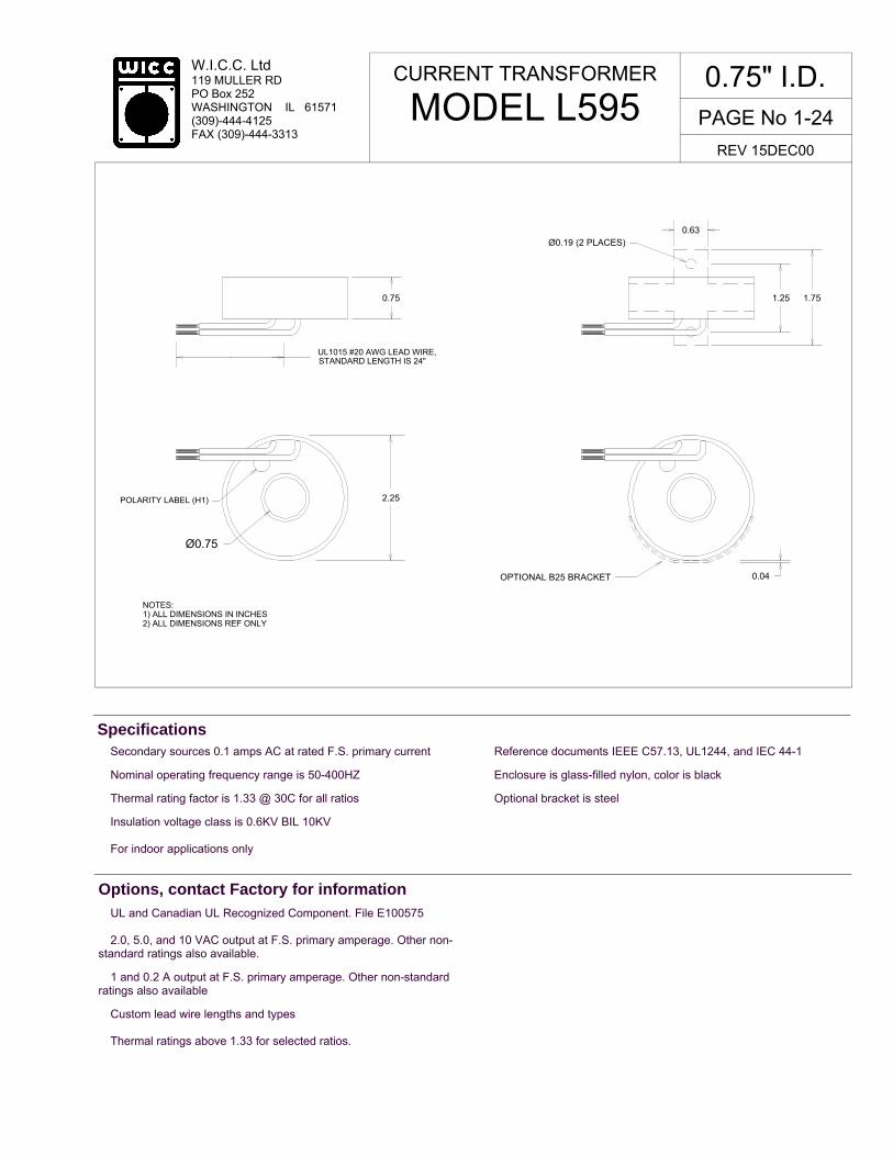
� Secondary sources 0.1 amps AC at rated F.S. primary current
� Nominal operating frequency range is 50-400HZ
� Thermal rating factor is 1.33 @ 30C for all ratios
� Insulation voltage class is 0.6KV BIL 10KV � For indoor applications only
� Reference documents IEEE C57.13, UL1244, and IEC 44-1
� Enclosure is glass-filled nylon, color is black
� Optional bracket is steel
Specifications
� UL and Canadian UL Recognized Component. File E100575 � 2.0, 5.0, and 10 VAC output at F.S. primary amperage. Other non-standard ratings also available.
� 1 and 0.2 A output at F.S. primary amperage. Other non-standard ratings also available
� Custom lead wire lengths and types � Thermal ratings above 1.33 for selected ratios.
Options, contact Factory for information
CURRENT TRANSFORMER
MODEL L595 0.75" I.D.
REV 15DEC00
UL1015 #20 AWG LEAD WIRE,
NOTES:1) ALL DIMENSIONS IN INCHES2) ALL DIMENSIONS REF ONLY
Ø0.75
2.25
0.75
STANDARD LENGTH IS 24"
POLARITY LABEL (H1)
0.63
1.25 1.75
Ø0.19 (2 PLACES)
OPTIONAL B25 BRACKET 0.04

PAGE No 1-25
W.I.C.C. Ltd 119 MULLER RD PO Box 252 WASHINGTON IL 61571 (309)-444-4125 FAX (309)-444-3313
TYPICAL EXCITATION CURVE for WICC MODEL L595 at 60HZ
10-5
10-4
10-3
10-2
10-1
100
EXCITING CURRENT (amp)
10-3
10-2
10-1
100
101
102
IND
UC
ED
VO
LT
AG
E (
volt)
W.I.C.C. PART NUMBER *
RATIO
ACCURACY @ 60HZ, pf = 0.95
± % BURDEN (ohm)
NOMINAL WINDING RESISTANCE (ohm)
L595-025-02-Lxxx L595-050-02-Lxxx L595-075-02-Lxxx L595-100-02-Lxxx L595-150-02-Lxxx L595-200-02-Lxxx
25:0.1A 50:0.1A 75:0.1A
100:0.1A 150:0.1A 200:0.1A
2.0 1.0 1.0 1.0 1.0 1.0
5 10 25 50
125 225
2.0 6.2 9.6 20 32 45
CURRENT TRANSFORMER
MODEL L595 0.75" I.D.
REV 15DEC00
* "Lxxx" describes LEAD WIRE termination where "xxx" is the lead length in inches. For example, "L24" represents 24 inch long lead wires.
25:0
.1A
50:0
.1A 10
0:0.
1A
75:0
.1A
150:
0.1A
20
0:0.
1A

W.I.C.C. Ltd 119 MULLER RD PO Box 252 WASHINGTON IL 61571 (309)-444-4125 FAX (309)-444-3313
PAGE No 1-26
CURRENT TRANSFORMER
MODEL MW 3.50" I.D.
REV 15DEC00
� Secondary sources 5 amps AC at rated F.S. primary current
� Nominal operating frequency range is 50-400HZ
� Thermal rating factor is 1.33 @ 30C for ratios up to 2000:5A, 1.15 @ 30C for ratios of 2000:5A and above
� Insulation voltage class is 0.6KV BIL 10KV
� For indoor applications only
� Reference documents IEEE C57.13, UL1244, and IEC 44-1
� Enclosure is made of glass-filled Nylon, color is black
� Optional bracket is aluminum, optional plate is XX phenolic
Specifications
� UL and Canadian UL Recognized Component. File E100575
� 2.0, 5.0, and 10 VAC output at F.S. primary amperage. Other non-standard ratings also available.
� 1, 0.2, and 0.1 A output at F.S. primary amperage. Other non-standard ratings also available
� 8-32 Brass Stud Terminals or #16 AWG UL 1015 Lead Wires. Choice of stud location.
� Custom lead wire lengths and types
� Thermal ratings above 1.33 for selected ratios.
� Available with B3 and B31 brackets. See Bracket Data Section for dimensions.
� Center tap and custom multi tap winding arrangements
Options, contact Factory for information
TERMINAL OPTION LEAD WIRE OPTION
UL 1015 #16 AWG LEAD WIRE,STANDARD LENGTH IS 24"
8-32 BRASS STUDS(2 PLACES)
3.50
5.75
1.15
6.00
0.25x0.5 SLOT(2 PLACES)
OPTIONAL B1 BRACKET
(4 PLACES)
OPTIONAL P6 PLATE
TOP TERMINAL OPTION
0.75
5.65
1.36
4.655.65
NOTES1). ALL DIMENSIONS IN INCHES2). ALL DIMENSIONS REF ONLY
POLARITY LABEL
5.657.00
3.15
Ø0.25
4.655.65

PAGE No 1-27
W.I.C.C. Ltd 119 MULLER RD PO Box 252 WASHINGTON IL 61571 (309)-444-4125 FAX (309)-444-3313
10-4
10-3
10-2
10-1
100
101
EXCITING CURRENT (amp)
TYPICAL EXCITATION CURVE for WICC MODEL MW at 60HZ
10-3
10-2
10-1
100
101
102
IND
UC
ED
VO
LT
AG
E (
volt)
* "xxx" describes termination: "T" FOR BRASS STUDS, "TT" FOR BRASS STUDS in top terminal configuration, and "Lyyy" FOR LEAD WIRES (Where "yyy" is the lead length in inches. For example, "L24" represents 24 inch long lead wires.)
W.I.C.C. PART NUMBER *
RATIO
ACCURACY @ 60HZ
± % BURDEN (VA)
NOMINAL WINDING RESISTANCE (ohm)
MW-300-00-xxx MW-400-00-xxx MW-500-00-xxx MW-600-00-xxx MW-800-00-xxx
MW-1000-00-xxx MW-1200-00-xxx MW-1500-00-xxx MW-1600-00-xxx MW-2000-00-xxx MW-2500-00-xxx MW-3000-00-xxx MW-4000-00-xxx
300:5A 400:5A 500:5A 600:5A 800:5A 1000:5A 1200:5A 1500:5A 1600:5A 2000:5A 2500:5A 3000:5A 4000:5A
1.5 1.0 1.0 1.0 1.0 1.0 1.0 1.0 1.0 1.0 1.0 1.0 1.0
2.0 2.0 4.0 6.0 10 12 20 15 15 12 15 25 45
0.06 0.08 0.10 0.12 0.17 0.22 0.25 0.50 0.53 0.67 0.85 1.0 1.4
CURRENT TRANSFORMER
MODEL MW 3.50" I.D.
REV 15DEC00
300:
5A
400:
5A
500:
5A
600:
5A
1500
:5A
3000
:5
4000
:5A

W.I.C.C. Ltd 119 MULLER RD PO Box 252 WASHINGTON IL 61571 (309)-444-4125 FAX (309)-444-3313
PAGE No 1-28
CURRENT TRANSFORMER
MODEL MWX 3.50" I.D.
REV 15DEC00
� Secondary sources 5 amps AC at rated F.S. primary current
� Nominal operating frequency range is 50-400HZ
� Thermal rating factor is 1.33 @ 30C for all ratios
� Insulation voltage class is 0.6KV BIL 10KV
� For indoor applications only
� Reference documents IEEE C57.13, UL1244, and IEC 44-1
� Enclosure is made of glass-filled Nylon, color is black
� Optional bracket is aluminum, optional plate is XX phenolic
Specifications
� UL and Canadian UL Recognized Component. File E100575
� 8-32 Brass Stud Terminals or #16 AWG UL 1015 Lead Wires. Choice of stud location.
� Custom lead wire lengths and types
� Thermal ratings above 1.33 for selected ratios.
� Available with B3 and B31 brackets. See Bracket Data Section for dimensions.
� Center tap and custom multi tap winding arrangements
Options, contact Factory for information
TERMINAL OPTION LEAD WIRE OPTION
UL 1015 #16 AWG LEAD WIRE,STANDARD LENGTH IS 24"
8-32 BRASS STUDS(2 PLACES)
3.50
5.75
1.15
6.00
0.25x0.5 SLOT(2 PLACES)
OPTIONAL B1 BRACKET
(4 PLACES)
OPTIONAL P6 PLATE
TOP TERMINAL OPTION
0.75
5.65
1.36
4.655.65
NOTES1). ALL DIMENSIONS IN INCHES2). ALL DIMENSIONS REF ONLY
POLARITY LABEL
5.657.00
3.15
Ø0.25
4.655.65

PAGE No 1-29
W.I.C.C. Ltd 119 MULLER RD PO Box 252 WASHINGTON IL 61571 (309)-444-4125 FAX (309)-444-3313
10-4
10-3
10-2
10-1
100
101
EXCITING CURRENT (amp)
10-3
10-2
10-1
101
102
IND
UC
ED
VO
LT
AG
E (
volt)
100
TYPICAL EXCITATION CURVE for WICC MODEL MWX at 60HZ
* "xxx" describes termination: "T" FOR BRASS STUDS, "TT" FOR BRASS STUDS in top terminal configuration, and "Lyyy" FOR LEAD WIRES (Where "yyy" is the lead length in inches. For example, "L24" represents 24 inch long lead wires.)
CURRENT TRANSFORMER
MODEL MWX 3.50" I.D.
REV 15DEC00
400:
5A
300:
5A
750:
5A
500:
5A 10
00:5
1500
:5
2000
:5A
W.I.C.C. PART NUMBER *
RATIO
ANSI ACCURACY CLASS @ 60HZ NOMINAL WINDING RESISTANCE (ohm)
MWX-100-00-xxx MWX-200-00-xxx MWX-300-00-xxx MWX-400-00-xxx MWX-500-00-xxx MWX-600-00-xxx MWX-750-00-xxx MWX-1000-00-xxx MWX-1200-00-xxx MWX-1500-00-xxx MWX-2000-00-xxx
100:5A 200:5A 300:5A 400:5A 500:5A 600:5A 750:5A 1000:5A 1200:5A 1500:5A 2000:5A
0.02 0.04 0.06 0.08 0.10 0.12 0.14 0.19 0.25 0.32 0.44
B0.1 4.8 1.2 0.6 0.6 0.3 0.3 0.3 0.3 0.3 0.3 0.3
B0.2 - -
1.2 0.6 0.6 0.3 0.3 0.3 0.3 0.3 0.3
B0.5 - - -
1.2 1.2 0.6 0.6 0.3 0.3 0.3 0.3
B0.9 - - - -
1.2 1.2 0.6 0.6 0.6 0.3 0.3
B1.8 - - - - - -
1.2 0.6 0.6 0.6 0.3
RELAY CLASS
- - - - - - -
C10 C10 C10 C20
200:
5A
100:
5A

W.I.C.C. Ltd 119 MULLER RD PO Box 252 WASHINGTON IL 61571 (309)-444-4125 FAX (309)-444-3313
PAGE No 1-30
� Secondary sources 5 amps AC at rated F.S. primary current
� Nominal operating frequency range is 50-400HZ
� Thermal rating factor is 1.33 @ 30C for ratios up to 3000:5A, 1.15 @ 30C for ratios of 3000:5A and above
� Insulation voltage class is 0.6KV BIL 10KV
� For indoor applications only
� Reference documents IEEE C57.13, UL1244, and IEC 44-1
� Enclosure is glass-filled nylon, color is black
� Optional bracket is aluminum
Specifications
� UL and Canadian UL Recognized Component. File E100575
� 2.0, 5.0, and 10 VAC output at F.S. primary amperage. Other non-standard ratings also available.
� 1, 0.2, and 0.1 A output at F.S. primary amperage. Other non-standard ratings also available
� 8-32 Brass Stud Terminals or #16 AWG UL 1015 Lead Wires
� Custom lead wire lengths and types
� Thermal ratings above 1.33 for selected ratios.
� Center tap and custom multi tap winding arrangements
Options, contact Factory for information
CURRENT TRANSFORMER
MODEL N
4.25" I.D.
REV 15DEC00
4.25
0.75
5.75
7.00
UL 1015 #16 AWG LEAD WIRE,STANDARD LENGTH IS 24"
SCREW CLAMPFOR SS BAND
OPTIONAL B1BRACKET
0.25 x 0.50 SLOT(2 PLACES)
SS BAND SECURES BRACKET(view of screw clamp band omitted for clarity)
TERMINAL OPTION LEAD WIRE OPTION
NOTES1). ALL DIMENSIONS IN INCHES2). ALL DIMENSIONS REF ONLY
7.13
6.75
8-32 BRASS STUD (2 PLACES)
POLARITY LABEL (H1)
3.75
1.16
1.36
Ø0.39(4 PLACES)
OPTIONAL P7MOUNTING
PLATE
5.44
6.75
5.44 6.75

PAGE No 1-31
W.I.C.C. Ltd 119 MULLER RD PO Box 252 WASHINGTON IL 61571 (309)-444-4125 FAX (309)-444-3313
TYPICAL EXCITATION CURVE for WICC MODEL N at 60HZ
10-3
10-2
10-1
100
101
102
IND
UC
ED
VO
LT
AG
E (
volt)
10-4
10-3
10-2
10-1
100
101
EXCITING CURRENT (amp)
W.I.C.C. PART NUMBER *
RATIO
ACCURACY @ 60HZ, pf = 0.95
± % BURDEN (VA)
NOMINAL WINDING RESISTANCE (ohm)
N-500-00-xxx N-750-00-xxx
N-1000-00-xxx N-1600-00-xxx N-2000-00-xxx N-2500-00-xxx N-3000-00-xxx
500:5A 750:5A 1000:5A 1600:5A 2000:5A 2500:5A 3000:5A
1.0 1.0 1.0 1.0 1.0 1.0 1.0
3.0 7.5 15 25 40 40 50
0.14 0.21 0.28 0.41 0.52 0.81 1.0
CURRENT TRANSFORMER
MODEL N
4.25" I.D.
REV 15DEC00
500:5A
750:5
A
1000
:5A
1600
:5A
* "xxx" describes termination: "T" FOR BRASS STUDS, "Lyyy" FOR LEAD WIRES (Where "yyy" is the lead length in inches. For example, "L24" represents 24 inch long lead wires.)
2000
:5A
2500
:5A
3000
:5A

W.I.C.C. Ltd 119 MULLER RD PO Box 252 WASHINGTON IL 61571 (309)-444-4125 FAX (309)-444-3313
PAGE No 1-32
CURRENT TRANSFORMER
MODEL ND 4.25" I.D.
REV 15DEC00
� Secondary sources 5 amps AC at rated F.S. primary current
� Nominal operating frequency range is 50-400HZ
� Thermal rating factor is 1.33 @ 30C for ratios up to 4250:5A, 1.15 @ 30C for ratios of 4250:5A and above
� Insulation voltage class is 0.6KV BIL 10KV
� For indoor applications only
� Reference documents IEEE C57.13, UL1244, and IEC 44-1
� Enclosure is made of glass-filled Nylon, color is black
� Optional bracket is steel
Specifications
� UL and Canadian UL Recognized Component. File E100575
� 2.0, 5.0, and 10 VAC output at F.S. primary current. Other non-standard ratings also available
� 1, 0.2, and 0.1 A output at F.S. primary current. Other non-standard ratings also available
� 8-32 Brass Stud Terminals or #16 AWG UL 1015 Lead Wires. Choice of stud location
� Custom lead wire lengths and types
� Thermal ratings above 1.33 for selected ratios
� Available with B20 bracket kit. See Bracket Data Section for dimensions
� Center tap and custom multi tap winding arrangements
Options, contact Factory for information
UL 1015 #16 AWG LEAD WIRE,STANDARD LENGTH IS 24"
0.26 x 0.63 THROUGH SLOT (4 PLACES)
OPTIONAL B20 MOUNTINGBRACKET KIT
8-32 BRASS STUD (2 PLACES)
POLARITY LABEL (2 PLACES)
NOTES1). ALL DIMENSIONS IN INCHES2). ALL DIMENSIONS REF ONLY
POLARITY LABEL
5.75
1.19 2.88
3.81
4.88
3.50
5.00
6.00
5.00 6.00
1.25 0.88
SIDE TERMINAL OPTION LEAD WIRE OPTION
4.25
TOP TERMINALOPTION

PAGE No 1-33
W.I.C.C. Ltd 119 MULLER RD PO Box 252 WASHINGTON IL 61571 (309)-444-4125 FAX (309)-444-3313
10-3
10-2
10-1
100
101
102
IND
UC
ED
VO
LT
AG
E (
volt)
10-4
10-3
10-2
10-1
100 101
EXCITING CURRENT (amp)
TYPICAL EXCITATION CURVE for WICC MODEL ND at 60HZ
* "xxx" describes termination: "T" FOR BRASS STUDS, "TT" FOR BRASS STUDS in top terminal configuration, and "Lyyy" FOR LEAD WIRES (Where "yyy" is the lead length in inches. For example, "L24" represents 24 inch long lead wires.)
W.I.C.C. PART NUMBER *
RATIO
ACCURACY @ 60HZ
± % BURDEN (VA)
NOMINAL WINDING RESISTANCE (ohm)
ND-300-00-xxx ND-500-00-xxx ND-600-00-xxx ND-800-00-xxx
ND-1000-00-xxx ND-1200-00-xxx ND-1500-00-xxx ND-1600-00-xxx ND-2000-00-xxx ND-2500-00-xxx ND-3000-00-xxx ND-4000-00-xxx ND-5000-00-xxx
300:5A 500:5A 600:5A 800:5A 1000:5A 1200:5A 1500:5A 1600:5A 2000:5A 2500:5A 3000:5A 4000:5A 5000:5A
1.5 1.0 1.0 1.0 1.0 1.0 1.0 1.0 1.0 1.0 1.0 1.0 1.0
2.0 2.5 4.0 8.5 15 20 25 30 25 25 20 25 30
0.07 0.11 0.14 0.18 0.22 0.27 0.33 0.36 0.41 0.52 0.54 0.76 1.2
CURRENT TRANSFORMER
MODEL ND 4.25" I.D.
REV 15DEC00
300:
5A
500:
5A
600:
5A
1500
:5A
4000
:5A
5000
:5A
800:
5A
1000
:5A
1200
:52000
:5
3000
:5A

W.I.C.C. Ltd 119 MULLER RD PO Box 252 WASHINGTON IL 61571 (309)-444-4125 FAX (309)-444-3313
CURRENT TRANSFORMER
MODEL NDX 4.25" I.D.
REV 15DEC00
� Secondary sources 5 amps AC at rated F.S. primary current
� Nominal operating frequency range is 50-400HZ
� Thermal rating factor is 1.33 @ 30C for ratios up to 4250:5A, 1.15 @ 30C for ratios of 4250:5A and above
� Insulation voltage class is 0.6KV BIL 10KV
� For indoor applications only
� Reference documents IEEE C57.13, UL1244, and IEC 44-1
� Enclosure is made of glass-filled Nylon, color is black
� Optional bracket is steel
Specifications
� UL and Canadian UL Recognized Component. File E100575
� 2.0, 5.0, and 10 VAC output at F.S. primary current. Other non-standard ratings also available
� 1, 0.2, and 0.1 A output at F.S. primary current. Other non-standard ratings also available
� 8-32 Brass Stud Terminals or #16 AWG UL 1015 Lead Wires. Choice of stud location
� Custom lead wire lengths and types
� Thermal ratings above 1.33 for selected ratios
� Available with B20 bracket kit. See Bracket Data Section for dimensions
� Center tap and custom multi tap winding arrangements
Options, contact Factory for information
UL 1015 #16 AWG LEAD WIRE,STANDARD LENGTH IS 24"
0.26 x 0.63 THROUGH SLOT (4 PLACES)
OPTIONAL B20 MOUNTINGBRACKET KIT
8-32 BRASS STUD (2 PLACES)
POLARITY LABEL (2 PLACES)
NOTES1). ALL DIMENSIONS IN INCHES2). ALL DIMENSIONS REF ONLY
POLARITY LABEL
5.75
1.19 2.88
3.81
4.88
3.50
5.00
6.00
5.00 6.00
1.25 0.88
SIDE TERMINAL OPTION LEAD WIRE OPTION
4.25
TOP TERMINALOPTION
PAGE No 1-34

W.I.C.C. Ltd 119 MULLER RD PO Box 252 WASHINGTON IL 61571 (309)-444-4125 FAX (309)-444-3313
TYPICAL EXCITATION CURVE for WICC MODEL NDX at 60HZ
10-4
10-3
10-1
100
101
EXCITING CURRENT (amp)
10-2
10-3
10-2
10-1
100
101
102
IND
UC
ED
VO
LT
AG
E (
volt)
* "xxx" describes termination: "T" FOR BRASS STUDS, "TT" FOR BRASS STUDS in top terminal configuration, and "Lyyy" FOR LEAD WIRES (Where "yyy" is the lead length in inches. For example, "L24" represents 24 inch long lead wires.)
W.I.C.C. PART NUMBER *
RATIO
ACCURACY @ 60HZ
± % BURDEN (VA)
NOMINAL WINDING RESISTANCE (ohm)
NDX-300-00-xxx NDX-500-00-xxx NDX-600-00-xxx NDX-800-00-xxx NDX-1000-00-xxx NDX-1200-00-xxx NDX-1500-00-xxx NDX-1600-00-xxx NDX-2000-00-xxx NDX-2500-00-xxx NDX-3000-00-xxx NDX-4000-00-xxx
300:5A 500:5A 600:5A 800:5A 1000:5A 1200:5A 1500:5A 1600:5A 2000:5A 2500:5A 3000:5A 4000:5A
1.0 1.0 1.0 1.0 1.0 1.0 1.0 1.0 1.0 1.0 1.0 1.0
6.0 20 25 50 75
100 80 80
100 65 65 75
0.05 0.08 0.12 0.16 0.22 0.31 0.33 0.36 0.44 0.48 0.53 0.76
CURRENT TRANSFORMER
MODEL NDX 4.25" I.D.
REV 15DEC00
200:
5A
250:
5A
300:
5A
800:
5A
400:
5A
500:
5A
600:
5A
1000
:5A
1200
:5A
PAGE No 1-35

W.I.C.C. Ltd 119 MULLER RD PO Box 252 WASHINGTON IL 61571 (309)-444-4125 FAX (309)-444-3313
CURRENT TRANSFORMER
MODEL NDX 4.25" I.D.
REV 15DEC00
10-4
10-3
10-2
10-1
100
101
EXCITING CURRENT (amp)
10-3
10-2
10-1
100
101
102
IND
UC
ED
VO
LT
AG
E (
volt)
TYPICAL EXCITATION CURVE for WICC MODEL NDX at 60HZ
10-3
10-2
10-1
100
101
102
IND
UC
ED
VO
LT
AG
E (
volt)
10-4
10-3
10-2
10-1
100
101
EXCITING CURRENT (amp)
TYPICAL EXCITATION CURVE for WICC MODEL NDX at 60HZ
2500
:5A
3000
:5A
4000
:5A
1500
:5A
2000
:5A
PAGE No 1-36

W.I.C.C. Ltd 119 MULLER RD PO Box 252 WASHINGTON IL 61571 (309)-444-4125 FAX (309)-444-3313
BLANK PAGE
PAGE No 1-37
W.I.C.C. Ltd 119 MULLER RD PO Box 252 WASHINGTON IL 61571 (309)-444-4125 FAX (309)-444-3313
PAGE No 1-38
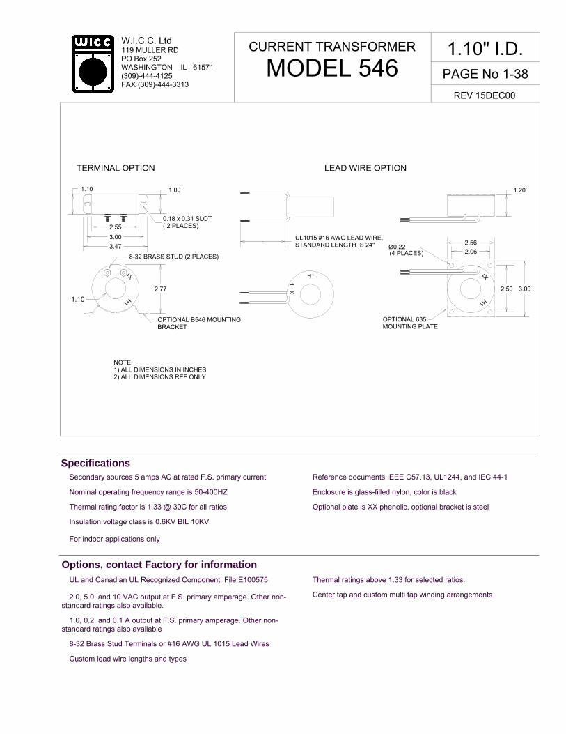
� Secondary sources 5 amps AC at rated F.S. primary current
� Nominal operating frequency range is 50-400HZ
� Thermal rating factor is 1.33 @ 30C for all ratios
� Insulation voltage class is 0.6KV BIL 10KV � For indoor applications only
� Reference documents IEEE C57.13, UL1244, and IEC 44-1
� Enclosure is glass-filled nylon, color is black
� Optional plate is XX phenolic, optional bracket is steel
Specifications
� UL and Canadian UL Recognized Component. File E100575 � 2.0, 5.0, and 10 VAC output at F.S. primary amperage. Other non-standard ratings also available.
� 1.0, 0.2, and 0.1 A output at F.S. primary amperage. Other non-standard ratings also available
� 8-32 Brass Stud Terminals or #16 AWG UL 1015 Lead Wires
� Custom lead wire lengths and types
� Thermal ratings above 1.33 for selected ratios.
� Center tap and custom multi tap winding arrangements
Options, contact Factory for information
CURRENT TRANSFORMER
MODEL 546 1.10" I.D.
REV 15DEC00
TERMINAL OPTION LEAD WIRE OPTION
1.10 1.00
2.55
3.00
3.47
0.18 x 0.31 SLOT( 2 PLACES)
2.77
1.10
NOTE:1) ALL DIMENSIONS IN INCHES2) ALL DIMENSIONS REF ONLY
UL1015 #16 AWG LEAD WIRE,STANDARD LENGTH IS 24"
(4 PLACES)
2.56
2.06
2.50 3.00
Ø0.22
OPTIONAL B546 MOUNTINGBRACKET
1.20
OPTIONAL 635MOUNTING PLATE
X1
H1
H1
X1
X1
H1
8-32 BRASS STUD (2 PLACES)

PAGE No 1-39
W.I.C.C. Ltd 119 MULLER RD PO Box 252 WASHINGTON IL 61571 (309)-444-4125 FAX (309)-444-3313
TYPICAL EXCITATION CURVE for WICC MODEL 546 at 60HZ
10-4
10-3
10-2
10-1
100
101
EXCITING CURRENT (amp)
10-4
10-3
10-2
10-1
100
101
IND
UC
ED
VO
LT
AG
E (
volt)
W.I.C.C. PART NUMBER *
RATIO
ACCURACY @ 60HZ, pf = 0.95
± % BURDEN (VA)
NOMINAL WINDING RESISTANCE (ohm)
546-050-00-xxx 546-060-00-xxx 546-075-00-xxx 546-100-00-xxx 546-125-00-xxx 546-150-00-xxx 546-200-00-xxx 546-250-00-xxx 546-300-00-xxx 546-400-00-xxx
50:5A 60:5A 75:5A
100:5A 125:5A 150:5A 200:5A 250:5A 300:5A 400:5A
3.0 2.0 2.0 1.0 1.0 1.0 1.0 1.0 1.0 1.0
2.0 2.0 2.0 2.0 2.5 4.0 5.0 7.5 10 15
0.007 0.008 0.01 0.02 0.025 0.03 0.04 0.052 0.062 0.083
CURRENT TRANSFORMER
MODEL 546 1.10" I.D.
REV 15DEC00
50:5
A
* "xxx" describes termination: "T" FOR BRASS STUDS, "Lyyy" FOR LEAD WIRES (Where "yyy" is the lead length in inches. For example, "L24" represents 24 inch long lead wires.)
60:5
A
75:5
A 10
0:5A
125:
5A
150:
5A
250:
5A
200:
5A
300:
5A
400:
5A

W.I.C.C. Ltd 119 MULLER RD PO Box 252 WASHINGTON IL 61571 (309)-444-4125 FAX (309)-444-3313
PAGE No 1-40
� Secondary sources 5 amps AC at rated F.S. primary current
� Nominal operating frequency range is 50-400HZ
� Thermal rating factor is 2.00 @ 30C for ratios up to 800:5A, 1.50 @ 30C for ratios of 800:5A and above
� Insulation voltage class is 0.6KV BIL 10KV
� For indoor applications only
� Reference documents IEEE C57.13, UL1244, and IEC 44-1
� Enclosure is multi-layer tape buildup with heavy vinyl finish, color is black
� Optional bracket is aluminum, optional plate is XX phenolic
Specifications
� Medium voltage insulation classes (physical size increases)
� 1, 0.2, and 0.1 A output at F.S. primary amperage. Other non-standard ratings also available.
� Custom lead wire lengths and types.
� Thermal ratings above 1.50 for selected ratios
� Center tap and custom multi tap winding arrangements
Options, contact Factory for information
CURRENT TRANSFORMER
MODEL 591 2.25" I.D.
REV 15DEC00
5.38
4.38
Ø0.25(4 PLACES)
OPTIONAL P8 PLATE
5.384.38
OPTIONAL B1B BRACKET
2.25
UL 1015 #14 AWG LEAD WIRESTANDARD LENGTH IS 36"
5.61
7.00
5.25
2.00 2.25 2.44
2). ALL DIMENSIONS REF ONLY1). ALL DIMENSIONS IN INCHESNOTES
0.50 x 0.75SLOT (2 PLACES)
5.56H1 H1
POLARITYLABEL (H1)
SCREW CLAMPfor SS BAND
SS BAND SECURES BRACKET(view of screw clamp omitted for clarity)

PAGE No 1-41
W.I.C.C. Ltd 119 MULLER RD PO Box 252 WASHINGTON IL 61571 (309)-444-4125 FAX (309)-444-3313
10-4
10-3
10-2
10-1
100
101
EXCITING CURRENT (amp)
TYPICAL EXCITATION CURVE for WICC MODEL 591 at 60HZ
10-2
10-1
100
101
102
103
IND
UC
ED
VO
LT
AG
E (
volt)
W.I.C.C. PART NUMBER *
RATIO
ANSI ACCURACY CLASS @ 60HZ NOMINAL WINDING RESISTANCE (ohm)
591-050-00-Lyyy 591-075-00-Lyyy 591-100-00-Lyyy 591-150-00-Lyyy 591-200-00-Lyyy 591-300-00-Lyyy 591-400-00-Lyyy 591-500-00-Lyyy 591-600-00-Lyyy 591-800-00-Lyyy
591-1000-00-Lyyy
50:5A 75:5A
100:5A 150:5A 200:5A 300:5A 400:5A 500:5A 600:5A 800:5A 1000:5A
0.02 0.02 0.03 0.04 0.06 0.09 0.12 0.16 0.19 0.26 0.40
CURRENT TRANSFORMER
MODEL 591 2.25" I.D.
REV 15DEC00
* "Lyyy" descibes length of LEAD WIRES (Where "yyy" is the lead length in inches. For example, "L24" represents 24 inch long lead wires.)
B0.1 2.4 1.2 0.6 0.6 0.3 0.3 0.3 0.3 0.3 0.3 0.3
B0.2 - -
1.2 0.6 0.6 0.3 0.3 0.3 0.3 0.3 0.3
B0.5 - - -
1.2 0.6 0.6 0.3 0.3 0.3 0.3 0.3
B0.9 - - - -
1.2 0.6 0.6 0.3 0.3 0.3 0.3
B1.8 - - - - -
1.2 0.6 0.3 0.3 0.3 0.3
RELAY CLASS
- - -
C10 C10 C20 C20 C50 C50 C50
C100
50:5
A 75:5
A
100:
5A
150:
5A
200:
5A
300:
5A
500:
5A
600:
5A
400:
5A
800:
5A
1000
:5

W.I.C.C. Ltd 119 MULLER RD PO Box 252 WASHINGTON IL 61571 (309)-444-4125 FAX (309)-444-3313
PAGE No 1-42
ÿ Secondary sources 5 amps AC at rated F.S. primary current
ÿ Nominal operating frequency range is 50-400HZ
ÿ Thermal rating factor is 2.00 @ 30C for ratios up to 1000:5A, 1.50 @ 30C for ratios above 1000:5A
ÿ Insulation voltage class is 0.6KV BIL 10KV
ÿ For indoor applications only
ÿ Reference documents IEEE C57.13, UL1244, and IEC 44-1
ÿ Enclosure is multi-layer tape buildup with heavy vinyl finish, color is black
ÿ Optional bracket is aluminum, optional plate is XX phenolic
Specifications
ÿ Medium voltage insulation classes (lead wires only, physical size increases)
ÿ 1, 0.2, and 0.1 A output at F.S. primary amperage. Other non-standard ratings also available
ÿ 8-32 Screw Terminals or #14 AWG UL 1015 Lead Wires
ÿ Custom lead wire lengths and types
ÿ Thermal ratings above 2.00 for selected ratios
ÿ Center tap and custom multi tap winding arrangements
Options, contact Factory for information
CURRENT TRANSFORMER
MODEL 594 2.75" I.D.
REV 15DEC00
5.38
4.38
(4 PLACES)
OPTIONAL P8 PLATE
5.384.38
OPTIONAL B1B BRACKET
UL 1015 #14 AWG LEAD WIRESTANDARD LENGTH IS 36"
7.00
2.00
2). ALL DIMENSIONS REF ONLY1). ALL DIMENSIONS IN INCHESNOTES
0.50 x 0.75SLOT (2 PLACES)
H1 H12.75
SS BAND SECURES BRACKET(2 PLACES)(view of screw clamp omitted for clarity)
SCREW CLAMPFOR SS BAND
LEAD WIRE OPTION TERMINAL OPTION
8-32 BRASS SCREWTERMINALS(2 PLACES)
X1Ø0.25
5.63
5.63
5.94
3.19 3.38

PAGE No 1-43
W.I.C.C. Ltd 119 MULLER RD PO Box 252 WASHINGTON IL 61571 (309)-444-4125 FAX (309)-444-3313
TYPICAL EXCITATION CURVE for WICC MODEL 594 at 60HZ
10-4
10-3
10-2
10-1
100
101
EXCITING CURRENT (amp)
10-2
10-1
100
101
102
103
IND
UC
ED
VO
LT
AG
E (
volt)
CURRENT TRANSFORMER
MODEL 594 2.75" I.D.
REV 15DEC00
W.I.C.C. PART NUMBER *
RATIO
ANSI ACCURACY CLASS @ 60HZ NOMINAL WINDING RESISTANCE (ohm)
594-050-00-xxx 594-075-00-xxx 594-100-00-xxx 594-150-00-xxx 594-200-00-xxx 594-300-00-xxx 594-400-00-xxx 594-500-00-xxx 594-600-00-xxx 594-800-00-xxx 594-1000-00-xxx
50:5A 75:5A
100:5A 150:5A 200:5A 300:5A 400:5A 500:5A 600:5A 800:5A 1000:5A
0.02 0.03 0.04 0.05 0.07 0.10 0.14 0.21 0.25 0.33 0.52
B0.1 2.4 1.2 0.6 0.3 0.3 0.3 0.3 0.3 0.3 0.3 0.3
B0.2 -
2.4 1.2 0.6 0.3 0.3 0.3 0.3 0.3 0.3 0.3
B0.5 - - -
1.2 0.6 0.3 0.3 0.3 0.3 0.3 0.3
B0.9 - - - -
1.2 0.6 0.3 0.3 0.3 0.3 0.3
B1.8 - - - - -
1.2 0.6 0.3 0.3 0.3 0.3
RELAY CLASS
- C10 C10 C20 C20 C20 C50 C50 C50
C100 C100
* "xxx" describes termination: "T" FOR BRASS SCREW TERMINALS and "Lyyy" FOR LEAD WIRES (Where "yyy" is the lead length in inches. For example, "L24" represents 24 inch long lead wires.)
50:5
A
75:5
A
100:
5A
150:
5A
200:
5A
300:
5A 50
0:5A
600:
5A
400:
5A
800:
5A
1000
:5A
W.I.C.C. Ltd 119 MULLER RD PO Box 252 WASHINGTON IL 61571 (309)-444-4125 FAX (309)-444-3313
PAGE No 1-44
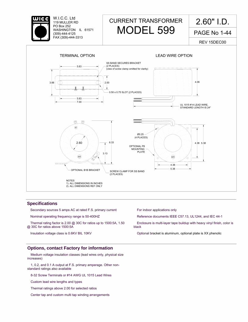
� Secondary sources 5 amps AC at rated F.S. primary current
� Nominal operating frequency range is 50-400HZ
� Thermal rating factor is 2.00 @ 30C for ratios up to 1500:5A, 1.50 @ 30C for ratios above 1500:5A
� Insulation voltage class is 0.6KV BIL 10KV
� For indoor applications only
� Reference documents IEEE C57.13, UL1244, and IEC 44-1
� Enclosure is multi-layer tape buildup with heavy vinyl finish, color is black
� Optional bracket is aluminum, optional plate is XX phenolic
Specifications
� Medium voltage insulation classes (lead wires only, physical size increases)
� 1, 0.2, and 0.1 A output at F.S. primary amperage. Other non-standard ratings also available
� 8-32 Screw Terminals or #14 AWG UL 1015 Lead Wires
� Custom lead wire lengths and types
� Thermal ratings above 2.00 for selected ratios
� Center tap and custom multi tap winding arrangements
Options, contact Factory for information
CURRENT TRANSFORMER
MODEL 599 2.60" I.D.
REV 15DEC00
X1
H1
TERMINAL OPTION LEAD WIRE OPTION
5.63
3.88 2.00
5.63
7.00
SS BAND SECURES BRACKET(2 PLACES) (view of screw clamp omitted for clarity)
0.50 x 0.75 SLOT (2 PLACES)
2.60
OPTIONAL B1B BRACKET
3.13
6.33
SCREW CLAMP FOR SS BAND(2 PLACES)
UL 1015 #14 LEAD WIRE,STANDARD LENGTH IS 24"
4.06
(4 PLACES)Ø0.25
OPTIONAL P8 MOUNTING
PLATE
4.38
5.38
4.38 5.38
NOTES1). ALL DIMENSIONS IN INCHES2). ALL DIMENSIONS REF ONLY
H1

PAGE No 1-45
W.I.C.C. Ltd 119 MULLER RD PO Box 252 WASHINGTON IL 61571 (309)-444-4125 FAX (309)-444-3313
TYPICAL EXCITATION CURVE for WICC MODEL 599 at 60HZ
10-2
10-1
100
101
102
103
IND
UC
ED
VO
LT
AG
E (
volt)
10-4
10-3
10-2
10-1
100
101
EXCITING CURRENT (amp)
CURRENT TRANSFORMER
MODEL 599 2.60" I.D.
REV 15DEC00
W.I.C.C. PART NUMBER *
RATIO
ANSI ACCURACY CLASS @ 60HZ NOMINAL WINDING RESISTANCE (ohm)
599-050-00-xxx 599-100-00-xxx 599-150-00-xxx 599-200-00-xxx 599-250-00-xxx 599-300-00-xxx 599-400-00-xxx 599-500-00-xxx 599-600-00-xxx 599-1000-00-xxx 599-1200-00-xxx 599-2000-00-xxx
50:5A 100:5A 150:5A 200:5A 250:5A 300:5A 400:5A 500:5A 600:5A 1000:5A 1200:5A 2000:5A
0.02 0.04 0.06 0.08 0.13 0.15 0.21 0.26 0.31 0.52 0.62 1.15
B0.1 2.4 0.6 0.3 0.3 0.3 0.3 0.3 0.3 0.3 0.3 0.3 0.3
B0.2 -
1.2 0.6 0.3 0.3 0.3 0.3 0.3 0.3 0.3 0.3 0.3
B0.5 - -
1.2 0.6 0.6 0.3 0.3 0.3 0.3 0.3 0.3 0.3
B0.9 - - -
0.6 0.6 0.6 0.3 0.3 0.3 0.3 0.3 0.3
B1.8 - - -
1.2 1.2 0.6 0.6 0.3 0.3 0.3 0.3 0.3
RELAY CLASS
- C10 C20 C20 C20 C50 C50 C50
C100 C100 C200 C200
* "xxx" describes termination: "T" FOR BRASS SCREW TERMINALS and "Lyyy" FOR LEAD WIRES (Where "yyy" is the lead length in inches. For example, "L24" represents 24 inch long lead wires.)
50:5
A 100:
5A
600:
5A
1000
:5A
500:
5A
1200
:5
2000
:5A
400:
5A
300:
5A
250:
5A
200:
5A
150:
5A

W.I.C.C. Ltd 119 MULLER RD PO Box 252 WASHINGTON IL 61571 (309)-444-4125 FAX (309)-444-3313
PAGE No 1-46
� Secondary sources 5 amps AC at rated F.S. primary current
� Nominal operating frequency range is 50-400HZ
� Thermal rating factor is 2.00 @ 30C for ratios up to 1500:5A, 1.50 @ 30C for ratios of 1500:5A up to 2000:5A, and 1.33 @ 30C for ratios above 2000:5A
� Insulation voltage class is 0.6KV BIL 10KV
� For indoor applications only
� Reference documents IEEE C57.13, UL1244, CSA CAN3-C13-M83, and IEC 44-1
� Enclosure is multi-layer tape buildup with heavy vinyl finish, color is black
� Optional bracket is aluminum, optional plate is XX phenolic
Specifications
� Medium voltage insulation classes (lead wires only, physical size increases)
� 1, 0.2, and 0.1 A output at F.S. primary amperage. Other non-standard ratings also available
� 8-32 Screw Terminals or #14 AWG UL 1015 Lead Wires
� Custom lead wire lengths and types
� Thermal ratings above 2.00 for selected ratios
� Center tap and custom multi tap winding arrangements
Options, contact Factory for information
CURRENT TRANSFORMER
MODEL 617 6.50" I.D.
REV 18DEC00
H1
X1
H1
TERMINAL OPTION LEAD WIRE OPTION
9.88
3.00
5.63
2.00
SS BAND SECURES BRACKET(2 PLACES)(view of screw clamp omitted for clarity)
0.50 x 0.75 SLOT (2 PLACES)8-32 BRASS SCREWTERMINAL (2 PLACES)
POLARITY LABEL
6.50
5.33
10.64
SCREW CLAMPFOR SS BAND
OPTIONAL B1BRACKET
OPTIONAL 617MOUNTING
PLATE
Ø0.65(4 PLACES)
8.389.88
8.38 9.88
3.38
UL 1015 #14 AWG LEAD WIRE,STANDARD LENGTH IS 24"
NOTES1). ALL DIMENSIONS IN INCHES2). ALL DIMENSIONS REF ONLY
POLARITY LABEL
7.00

PAGE No 1-47
W.I.C.C. Ltd 119 MULLER RD PO Box 252 WASHINGTON IL 61571 (309)-444-4125 FAX (309)-444-3313
10-4
10-3
10-2
10-1
100
101
EXCITING CURRENT (amp)
TYPICAL EXCITATION CURVE for WICC MODEL 617 at 60HZ
10-2
10-1
100
101
102
103
IND
UC
ED
VO
LT
AG
E (
volt)
W.I.C.C. PART NUMBER *
RATIO
ANSI ACCURACY CLASS @ 60HZ NOMINAL WINDING RESISTANCE (ohm)
617-100-00-xxx 617-150-00-xxx 617-200-00-xxx 617-300-00-xxx 617-400-00-xxx 617-600-00-xxx 617-800-00-xxx 617-1000-00-xxx 617-1200-00-xxx 617-1600-00-xxx 617-2000-00-xxx 617-3000-00-xxx 617-4000-00-xxx
100:5A 150:5A 200:5A 300:5A 400:5A 600:5A 800:5A 1000:5A 1200:5A 1600:5A 2000:5A 3000:5A 4000:5A
0.03 0.05 0.07 0.10 0.13 0.20 0.27 0.33 0.39 0.65 1.3 2.0 2.6
B0.1 1.2 1.2 0.6 0.3 0.3 0.3 0.3 0.3 0.3 0.3 0.3 0.3 0.3
B0.2 -
1.2 0.6 0.3 0.3 0.3 0.3 0.3 0.3 0.3 0.3 0.3 0.3
B0.5 - -
1.2 0.6 0.6 0.3 0.3 0.3 0.3 0.3 0.3 0.3 0.3
B0.9 - - -
1.2 0.6 0.3 0.3 0.3 0.3 0.3 0.3 0.3 0.3
B1.8 - - - -
1.2 0.6 0.3 0.3 0.3 0.3 0.3 0.3 0.3
RELAY CLASS
C10 C10 C20 C20 C50 C50
C100 C100 C100 C200 C200 C200 C400
* "xxx" describes termination: "T" FOR BRASS SCREW TERMINALS and "Lyyy" FOR LEAD WIRES (Where "yyy" is the lead length in inches. For example, "L24" represents 24 inch long lead wires.)
CURRENT TRANSFORMER
MODEL 617 6.50" I.D.
REV 18DEC00
100:
5A
150:
5A
200:
5A
300:
5A
400:
5A
600:
5A
1000
:5A
1200
:5A
800:
5A
1600
:5
2000
:5A
3000
:5
4000
:5A

W.I.C.C. Ltd 119 MULLER RD PO Box 252 WASHINGTON IL 61571 (309)-444-4125 FAX (309)-444-3313
PAGE No 1-48
� Secondary sources 1 amps AC at rated F.S. primary current
� Nominal operating frequency range is 50-400HZ
� Thermal rating factor is 1.33 @ 30C for all ratios
� Insulation voltage class is 0.6KV BIL 10KV
� For indoor applications only
� Reference documents IEEE C57.13, UL1244, CSA CAN3-C13-M83, and IEC 44-1
� Enclosure is glass-filled nylon, color is black
� Optional plate is XX phenolic, optional bracket is steel
Specifications
� UL and Canadian UL Recognized Component. File E100575 � 2.0, 5.0, and 10 VAC output at F.S. primary amperage. Other non-standard ratings also available.
� 5, 0.2, and 0.1 A output at F.S. primary amperage. Other non-standard ratings also available
� 8-32 Brass Stud Terminals or #18 AWG UL 1015 Lead Wires
� Custom lead wire lengths and types
� Thermal ratings above 1.33 for selected ratios.
� Center tap and custom multi tap winding arrangements
Options, contact Factory for information
CURRENT TRANSFORMER
MODEL 635 1.10" I.D.
REV 18DEC00
TERMINAL OPTION LEAD WIRE OPTION
1.10 1.00
2.55
3.00
3.47
0.18 x 0.31 SLOT( 2 PLACES)
2.77
1.10
NOTE:1) ALL DIMENSIONS IN INCHES2) ALL DIMENSIONS REF ONLY
UL1015 #18 AWG LEAD WIRE,STANDARD LENGTH IS 24"
(4 PLACES)
2.56
2.06
2.50 3.00
Ø0.22
OPTIONAL B546 MOUNTINGBRACKET
1.20
OPTIONAL 635MOUNTING PLATE
X1
H1
H1
X1
X1
H1
8-32 BRASS STUD (2 PLACES)

PAGE No 1-49
W.I.C.C. Ltd 119 MULLER RD PO Box 252 WASHINGTON IL 61571 (309)-444-4125 FAX (309)-444-3313
10-3
10-2
10-1
100
101
102
IND
UC
ED
VO
LT
AG
E (
volt)
TYPICAL EXCITATION CURVE for WICC MODEL 635 at 60HZ
10-5
10-4
10-3
10-2
10-1
100
EXCITING CURRENT (amp)
W.I.C.C. PART NUMBER *
RATIO
ACCURACY @ 60HZ, pf = 0.95
± % BURDEN (VA)
NOMINAL WINDING RESISTANCE (ohm)
635-050-01-xxx 635-060-01-xxx 635-075-01-xxx 635-100-01-xxx 635-125-01-xxx 635-150-01-xxx 635-200-01-xxx 635-250-01-xxx 635-300-01-xxx 635-400-01-xxx
50:1A 60:1A 75:1A
100:1A 125:1A 150:1A 200:1A 250:1A 300:1A 400:1A
3.0 2.0 1.5 1.0 1.0 1.0 1.0 1.0 1.0 1.0
1.0 1.0 1.0 1.0 2.0 3.0 5.0 7.5 10 15
0.05 0.06 0.15 0.31 0.38 0.57 0.95 1.20 1.45 2.00
CURRENT TRANSFORMER
MODEL 635 1.10" I.D.
REV 18DEC00
50:1
A
* "xxx" describes termination: "T" FOR BRASS STUDS, "Lyyy" FOR LEAD WIRES (Where "yyy" is the lead length in inches. For example, "L24" represents 24 inch long lead wires.)
60:1
A 75
:1A 15
0:1A
100:
1A
125:
1A 25
0:1A
200:
1A
300:
1A
400:
1A

W.I.C.C. Ltd 119 MULLER RD PO Box 252 WASHINGTON IL 61571 (309)-444-4125 FAX (309)-444-3313
PAGE No 1-50
� Secondary sources 0.1 amps AC at rated F.S. primary current
� Nominal operating frequency range is 50-400HZ
� Thermal rating factor is 1.33 @ 30C for all ratios
� Insulation voltage class is 0.6KV BIL 10KV
� For indoor applications only
� Reference documents IEEE C57.13, UL1244, CSA CAN3-C13-M83, and IEC 44-1
� Enclosure is glass-filled nylon, color is black
� Optional plate is XX phenolic, optional bracket is steel
Specifications
� UL and Canadian UL Recognized Component. File E100575 � 2.0, 5.0, and 10 VAC output at F.S. primary amperage. Other non-standard ratings also available.
� 5, 1, and 0.2 A output at F.S. primary amperage. Other non-standard ratings also available
� 8-32 Brass Stud Terminals or #20 AWG UL 1015 Lead Wires
� Custom lead wire lengths and types
� Thermal ratings above 1.33 for selected ratios.
� Center tap and custom multi tap winding arrangements
Options, contact Factory for information
CURRENT TRANSFORMER
MODEL 636 1.10" I.D.
REV 18DEC00
TERMINAL OPTION LEAD WIRE OPTION
1.10 1.00
2.55
3.00
3.47
0.18 x 0.31 SLOT( 2 PLACES)
2.77
1.10
NOTE:1) ALL DIMENSIONS IN INCHES2) ALL DIMENSIONS REF ONLY
UL1015 #20 AWG LEAD WIRE,STANDARD LENGTH IS 24"
(4 PLACES)
2.56
2.06
2.50 3.00
Ø0.22
OPTIONAL B546 MOUNTINGBRACKET
1.20
OPTIONAL 635MOUNTING PLATE
X1
H1
H1
X1
X1
H1
8-32 BRASS STUD (2 PLACES)

PAGE No 1-51
W.I.C.C. Ltd 119 MULLER RD PO Box 252 WASHINGTON IL 61571 (309)-444-4125 FAX (309)-444-3313
10-5
10-4
10-3
10-2
10-1
100
EXCITING CURRENT (amp)
TYPICAL EXCITATION CURVE for WICC MODEL 636 at 60HZ
10-2
10-1
100
101
102
103
IND
UC
ED
VO
LT
AG
E (
volt)
W.I.C.C. PART NUMBER *
RATIO
ACCURACY @ 60HZ, pf = 0.95
± % BURDEN (ohm)
NOMINAL WINDING RESISTANCE (ohm)
636-050-02-xxx 636-060-02-xxx 636-075-02-xxx 636-100-02-xxx 636-125-02-xxx 636-150-02-xxx 636-200-02-xxx 636-250-02-xxx 636-300-02-xxx 636-400-02-xxx
50:0.1A 60:0.1A 75:0.1A
100:0.1A 125:0.1A 150:0.1A 200:0.1A 250:0.1A 300:0.1A 400:0.1A
1.0 1.0 1.0 1.0 1.0 1.0 1.0 1.0 1.0 1.0
20 30 50
100 175 275 500 750 1150 1600
5.9 7.1 9.1 20 25 30 40 65 80 160
CURRENT TRANSFORMER
MODEL 636 1.10" I.D.
REV 18DEC00
50:0
.1A
* "xxx" describes termination: "T" FOR BRASS STUDS, "Lyyy" FOR LEAD WIRES (Where "yyy" is the lead length in inches. For example, "L24" represents 24 inch long lead wires.)
60:0
.1A
75:0
.1A 15
0:0.
1A
100:
0.1A
12
5:0.
1A 250:
0.1A
200:
0.1A
300:
0.1A
400:
0.1A

W.I.C.C. Ltd 119 MULLER RD PO Box 252 WASHINGTON IL 61571 (309)-444-4125 FAX (309)-444-3313
� Secondary sources 1 amps AC at rated F.S. primary current
� Nominal operating frequency range is 50-400HZ
� Thermal rating factor is 1.33 @ 30C for all ratios
� Insulation voltage class is 0.6KV BIL 10KV
� For indoor applications only
� Reference documents IEEE C57.13, UL1244, CSA CAN3-C13-M83, and IEC 44-1
� Enclosure is made of glass-filled Nylon, color is black
Specifications
� UL and Canadian UL Recognized Component. File E100575.
� 2.0, 5.0, and 10 VAC output at F.S. primary amperage. Other non-standard ratings also available.
� 5, 0.2, and 0.1 A output at F.S. primary amperage. Other non-standard ratings also available.
� 8-32 Brass Studs or #18 AWG UL 1015 Lead Wires.
� Custom lead wire lengths and types.
� Thermal ratings above 1.33 for selected ratios
� Housing with or without mounting flange (See Model 652F for flange design).
� Center tap and custom multi tap winding arrangements
Options, contact Factory for information
CURRENT TRANSFORMER
MODEL 652 2.50" I.D.
REV 18DEC00
OTHER LENGTHS AVAILABLE
TERMINAL OPTION LEAD WIRE OPTION
STANDARD LENGTH IS 24",
3.25
4.56
1.08
2.35
4.692.50
8-32 BRASS STUDS (2 PLACES)
UL 1015, #18 AWG LEAD WIRE
NOTES1). ALL DIMENSIONS IN INCHES2). ALL DIMENSIONS REF ONLY
(2 PLACES)
OPTIONAL B653 STEEL BRACKET
0.28x0.50 SLOT (2 PLACES)
3.71
0.44
Ø0.28
Ø0.41
3.50
PAGE No 1-52
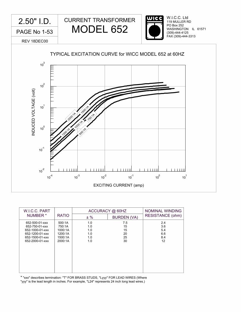
W.I.C.C. Ltd 119 MULLER RD PO Box 252 WASHINGTON IL 61571 (309)-444-4125 FAX (309)-444-3313
10-4
10-3
10-2
10-1
100
101
EXCITING CURRENT (amp)
10-2
10-1
100
101
102
103
IND
UC
ED
VO
LT
AG
E (
volt)
TYPICAL EXCITATION CURVE for WICC MODEL 652 at 60HZ
* "xxx" describes termination: "T" FOR BRASS STUDS, "Lyyy" FOR LEAD WIRES (Where "yyy" is the lead length in inches. For example, "L24" represents 24 inch long lead wires.)
W.I.C.C. PART NUMBER *
RATIO
ACCURACY @ 60HZ
± % BURDEN (VA)
NOMINAL WINDING RESISTANCE (ohm)
652-500-01-xxx 652-750-01-xxx 652-1000-01-xxx 652-1200-01-xxx 652-1500-01-xxx 652-2000-01-xxx
500:1A 750:1A 1000:1A 1200:1A 1500:1A 2000:1A
1.0 1.0 1.0 1.0 1.0 1.0
7.5 15 15 20 25 30
2.4 3.6 5.4 6.6 8.4 12
CURRENT TRANSFORMER
MODEL 652 2.50" I.D.
REV 18DEC00
500:
1A
750:
1A
1000
:1A
1500
:1A
2000
:1A
1200
:1A
PAGE No 1-53
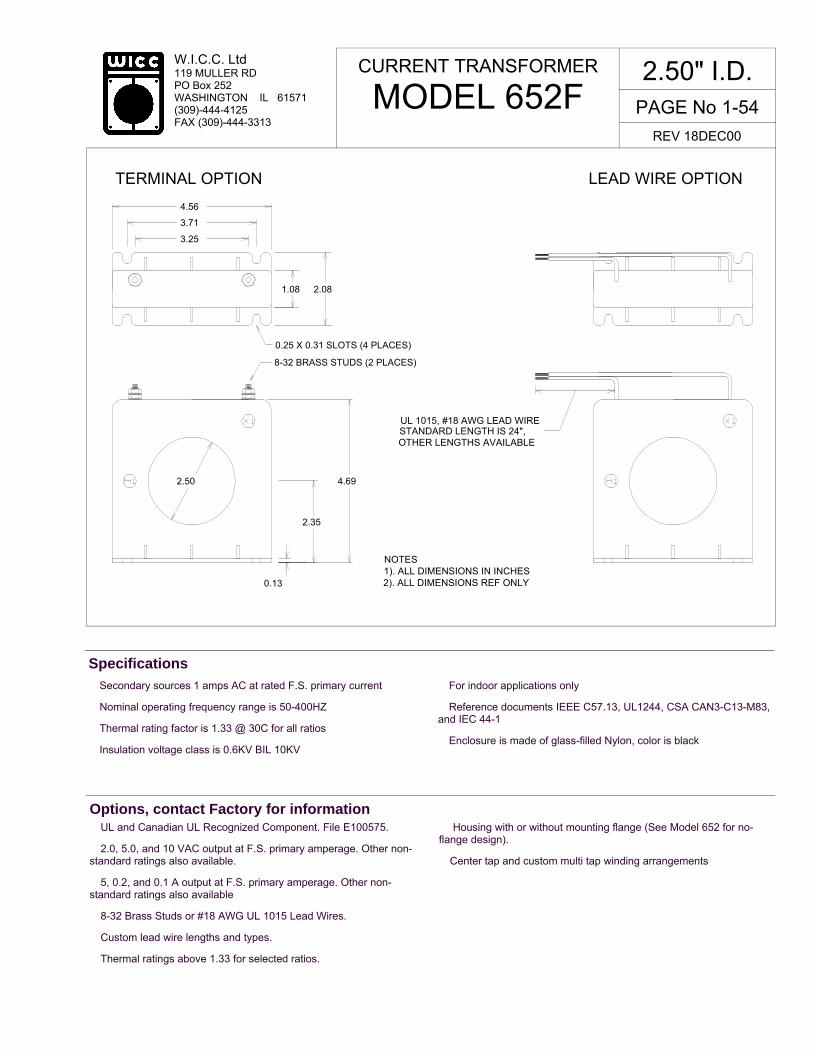
W.I.C.C. Ltd 119 MULLER RD PO Box 252 WASHINGTON IL 61571 (309)-444-4125 FAX (309)-444-3313
� Secondary sources 1 amps AC at rated F.S. primary current
� Nominal operating frequency range is 50-400HZ
� Thermal rating factor is 1.33 @ 30C for all ratios
� Insulation voltage class is 0.6KV BIL 10KV
� For indoor applications only
� Reference documents IEEE C57.13, UL1244, CSA CAN3-C13-M83, and IEC 44-1
� Enclosure is made of glass-filled Nylon, color is black
Specifications
CURRENT TRANSFORMER
MODEL 652F 2.50" I.D.
REV 18DEC00
� UL and Canadian UL Recognized Component. File E100575.
� 2.0, 5.0, and 10 VAC output at F.S. primary amperage. Other non-standard ratings also available.
� 5, 0.2, and 0.1 A output at F.S. primary amperage. Other non-standard ratings also available
� 8-32 Brass Studs or #18 AWG UL 1015 Lead Wires.
� Custom lead wire lengths and types.
� Thermal ratings above 1.33 for selected ratios.
� Housing with or without mounting flange (See Model 652 for no-flange design).
� Center tap and custom multi tap winding arrangements
Options, contact Factory for information
OTHER LENGTHS AVAILABLE
TERMINAL OPTION LEAD WIRE OPTION
STANDARD LENGTH IS 24",
3.25
3.71
4.56
1.08 2.08
0.13
2.35
4.692.50
0.25 X 0.31 SLOTS (4 PLACES)
8-32 BRASS STUDS (2 PLACES)
UL 1015, #18 AWG LEAD WIRE
NOTES1). ALL DIMENSIONS IN INCHES2). ALL DIMENSIONS REF ONLY
PAGE No 1-54

W.I.C.C. Ltd 119 MULLER RD PO Box 252 WASHINGTON IL 61571 (309)-444-4125 FAX (309)-444-3313
10-4
10-3
10-2
10-1
100
101
EXCITING CURRENT (amp)
10-2
10-1
100
101
102
103
IND
UC
ED
VO
LT
AG
E (
volt)
TYPICAL EXCITATION CURVE for WICC MODEL 652F at 60HZ
CURRENT TRANSFORMER
MODEL 652F 2.50" I.D.
REV 18DEC00
* "xxx" describes termination: "T" FOR BRASS STUDS, "Lyyy" FOR LEAD WIRES (Where "yyy" is the lead length in inches. For example, "L24" represents 24 inch long lead wires.)
W.I.C.C. PART NUMBER *
RATIO
ACCURACY @ 60HZ
± % BURDEN (VA)
NOMINAL WINDING RESISTANCE (ohm)
652F-500-01-xxx 652F-750-01-xxx
652F-1000-01-xxx 652F-1200-01-xxx 652F-1500-01-xxx 652F-2000-01-xxx
500:1A 750:1A 1000:1A 1200:1A 1500:1A 2000:1A
1.0 1.0 1.0 1.0 1.0 1.0
7.5 15 15 20 25 30
2.4 3.6 5.4 6.6 8.4 12
500:
1A
750:
1A
1000
:1A
1500
:1A
2000
:1A
1200
:1A
PAGE No 1-55
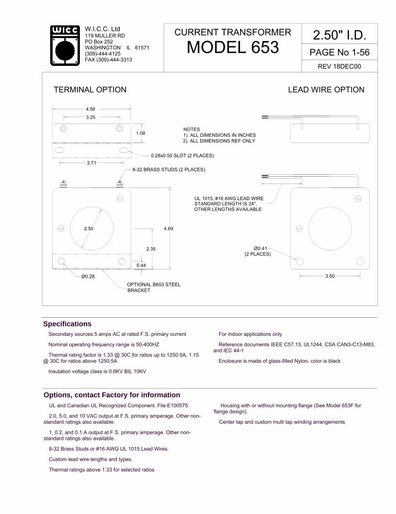
W.I.C.C. Ltd 119 MULLER RD PO Box 252 WASHINGTON IL 61571 (309)-444-4125 FAX (309)-444-3313
� Secondary sources 5 amps AC at rated F.S. primary current
� Nominal operating frequency range is 50-400HZ
� Thermal rating factor is 1.33 @ 30C for ratios up to 1250:5A, 1.15 @ 30C for ratios above 1250:5A
� Insulation voltage class is 0.6KV BIL 10KV
� For indoor applications only
� Reference documents IEEE C57.13, UL1244, CSA CAN3-C13-M83, and IEC 44-1
� Enclosure is made of glass-filled Nylon, color is black
Specifications
� UL and Canadian UL Recognized Component. File E100575.
� 2.0, 5.0, and 10 VAC output at F.S. primary amperage. Other non-standard ratings also available.
� 1, 0.2, and 0.1 A output at F.S. primary amperage. Other non-standard ratings also available.
� 8-32 Brass Studs or #16 AWG UL 1015 Lead Wires.
� Custom lead wire lengths and types.
� Thermal ratings above 1.33 for selected ratios
� Housing with or without mounting flange (See Model 653F for flange design).
� Center tap and custom multi tap winding arrangements
Options, contact Factory for information
CURRENT TRANSFORMER
MODEL 653 2.50" I.D.
REV 18DEC00
OTHER LENGTHS AVAILABLE
TERMINAL OPTION LEAD WIRE OPTION
STANDARD LENGTH IS 24",
3.25
4.56
1.08
2.35
4.692.50
8-32 BRASS STUDS (2 PLACES)
UL 1015, #16 AWG LEAD WIRE
NOTES1). ALL DIMENSIONS IN INCHES2). ALL DIMENSIONS REF ONLY
(2 PLACES)
OPTIONAL B653 STEEL BRACKET
0.28x0.50 SLOT (2 PLACES)
3.71
0.44
Ø0.28
Ø0.41
3.50
PAGE No 1-56

W.I.C.C. Ltd 119 MULLER RD PO Box 252 WASHINGTON IL 61571 (309)-444-4125 FAX (309)-444-3313
10-4
10-3
10-2
10-1
100
101
EXCITING CURRENT (amp)
TYPICAL EXCITATION CURVE for WICC MODEL 653 and 653F at 60HZ
10-3
10-2
10-1
100
101
IND
UC
ED
VO
LT
AG
E (
volt)
102
* "xxx" describes termination: "T" FOR BRASS STUDS, "Lyyy" FOR LEAD WIRES (Where "yyy" is the lead length in inches. For example, "L24" represents 24 inch long lead wires.)
W.I.C.C. PART NUMBER *
RATIO
ACCURACY @ 60HZ
± % BURDEN (VA)
NOMINAL WINDING RESISTANCE (ohm)
653-100-00-xxx 653-150-00-xxx 653-200-00-xxx 653-250-00-xxx 653-300-00-xxx 653-400-00-xxx 653-500-00-xxx 653-600-00-xxx 653-800-00-xxx 653-1000-00-xxx 653-1200-00-xxx 653-1500-00-xxx 653-1600-00-xxx
100:5A 150:5A 200:5A 250:5A 300:5A 400:5A 500:5A 600:5A 800:5A 1000:5A 1200:5A 1500:5A 1600:5A
3.0 1.5 1.0 1.0 1.0 1.0 1.0 1.0 1.0 1.0 1.0 1.0 1.0
2.0 2.0 2.0 2.0 2.0 4.0 6.5 10 15 15 20 20 25
0.02 0.03 0.04 0.04 0.05 0.10 0.12 0.14 0.19 0.22 0.27 0.42 0.45
CURRENT TRANSFORMER
MODEL 653 2.50" I.D.
REV 18DEC00
100:
5A
150:
5A
200:
5A
300:
5A
400:
5A
500:
5A
800:
5A
1000
:5A
1200
:5A
1500
:5A
PAGE No 1-57

W.I.C.C. Ltd 119 MULLER RD PO Box 252 WASHINGTON IL 61571 (309)-444-4125 FAX (309)-444-3313
� Secondary sources 5 amps AC at rated F.S. primary current
� Nominal operating frequency range is 50-400HZ
� Thermal rating factor is 1.33 @ 30C for ratios up to 1250:5A, 1.15 @ 30C for ratios above 1250:5A
� Insulation voltage class is 0.6KV BIL 10KV
� For indoor applications only
� Reference documents IEEE C57.13, UL1244, CSA CAN3-C13-M83, and IEC 44-1
� Enclosure is made of glass-filled Nylon, color is black
Specifications
CURRENT TRANSFORMER
MODEL 653F 2.50" I.D.
REV 18DEC00
� UL and Canadian UL Recognized Component. File E100575.
� 2.0, 5.0, and 10 VAC output at F.S. primary amperage. Other non-standard ratings also available.
� 1, 0.2, and 0.1 A output at F.S. primary amperage. Other non-standard ratings also available
� 8-32 Brass Studs or #16 AWG UL 1015 Lead Wires.
� Custom lead wire lengths and types.
� Thermal ratings above 1.33 for selected ratios.
� Housing with or without mounting flange (See Model 653 for no-flange design).
� Center tap and custom multi tap winding arrangements
Options, contact Factory for information
OTHER LENGTHS AVAILABLE
TERMINAL OPTION LEAD WIRE OPTION
STANDARD LENGTH IS 24",
3.25
3.71
4.56
1.08 2.08
0.13
2.35
4.692.50
0.25 X 0.31 SLOTS (4 PLACES)
8-32 BRASS STUDS (2 PLACES)
UL 1015, #16 AWG LEAD WIRE
NOTES1). ALL DIMENSIONS IN INCHES2). ALL DIMENSIONS REF ONLY
PAGE No 1-58

W.I.C.C. Ltd 119 MULLER RD PO Box 252 WASHINGTON IL 61571 (309)-444-4125 FAX (309)-444-3313
CURRENT TRANSFORMER
MODEL 653F 2.50" I.D.
REV 18DEC00
* "xxx" describes termination: "T" FOR BRASS STUDS, "Lyyy" FOR LEAD WIRES (Where "yyy" is the lead length in inches. For example, "L24" represents 24 inch long lead wires.)
W.I.C.C. PART NUMBER *
RATIO
ACCURACY @ 60HZ
± % BURDEN (VA)
NOMINAL WINDING RESISTANCE (ohm)
653F-100-00-xxx 653F-150-00-xxx 653F-200-00-xxx 653F-250-00-xxx 653F-300-00-xxx 653F-400-00-xxx 653F-500-00-xxx 653F-600-00-xxx 653F-750-00-xxx
653F-1000-00-xxx 653F-1200-00-xxx 653F-1500-00-xxx 653F-1600-00-xxx
100:5A 150:5A 200:5A 250:5A 300:5A 400:5A 500:5A 600:5A 750:5A 1000:5A 1200:5A 1500:5A 1600:5A
3.0 1.5 1.0 1.0 1.0 1.0 1.0 1.0 1.0 1.0 1.0 1.0 1.0
2.0 2.0 2.0 2.0 2.0 4.0 6.5 10 15 15 20 20 25
0.02 0.03 0.04 0.04 0.05 0.10 0.12 0.14 0.19 0.22 0.27 0.42 0.45
10-4
10-3
10-2
10-1
100
101
EXCITING CURRENT (amp)
TYPICAL EXCITATION CURVE for WICC MODEL 653 and 653F at 60HZ
10-3
10-2
10-1
100
101
IND
UC
ED
VO
LT
AG
E (
volt)
102
100:
5A
150:
5A
200:
5A
300:
5A
400:
5A
500:
5A
800:
5A
1000
:5A
1200
:5
1500
:5A
PAGE No 1-59

W.I.C.C. Ltd 119 MULLER RD PO Box 252 WASHINGTON IL 61571 (309)-444-4125 FAX (309)-444-3313
� Secondary sources 5 amps AC at rated F.S. primary current
� Nominal operating frequency range is 50-400HZ
� Thermal rating factor is 1.33 @ 30C for ratios up to 1250:5A, 1.15 @ 30C for ratios above 1250:5A
� Insulation voltage class is 0.6KV BIL 10KV
� For indoor applications only � Reference documents IEEE C57.13, UL1244, CSA CAN3-C13-M83, and IEC 44-1
� Enclosure is made of glass-filled Nylon, color is black
Specifications
� UL and Canadian UL Recognized Component. File E100575.
� 2.0, 5.0, and 10 VAC output at F.S. primary amperage. Other non-standard ratings also available.
� 1, 0.2, and 0.1 A output at F.S. primary amperage. Other non-standard ratings also available.
� 8-32 Brass Studs or #16 AWG UL 1015 Lead Wires.
� Custom lead wire lengths and types.
� Thermal ratings above 1.33 for selected ratios
� Housing with or without mounting flange (See Model 653FX for flange design).
� Center tap and custom multi tap winding arrangements
Options, contact Factory for information
CURRENT TRANSFORMER
MODEL 653X 2.50" I.D.
REV 18DEC00
OTHER LENGTHS AVAILABLE
TERMINAL OPTION LEAD WIRE OPTION
STANDARD LENGTH IS 24",
3.25
4.56
1.08
2.35
4.692.50
8-32 BRASS STUDS (2 PLACES)
UL 1015, #16 AWG LEAD WIRE
NOTES1). ALL DIMENSIONS IN INCHES2). ALL DIMENSIONS REF ONLY
(2 PLACES)
OPTIONAL B653 STEEL BRACKET
0.28x0.50 SLOT (2 PLACES)
3.71
0.44
Ø0.28
Ø0.41
3.50
PAGE No 1-60

W.I.C.C. Ltd 119 MULLER RD PO Box 252 WASHINGTON IL 61571 (309)-444-4125 FAX (309)-444-3313
10-3
10-2
10-1
100
101
102
IND
UC
ED
VO
LT
AG
E (
volt)
10-4
10-3
10-2
10-1
100
101
EXCITING CURRENT (amp)
TYPICAL EXCITATION CURVE for WICC MODEL 653X at 60HZ
* "xxx" describes termination: "T" FOR BRASS STUDS, "Lyyy" FOR LEAD WIRES (Where "yyy" is the lead length in inches. For example, "L24" represents 24 inch long lead wires.)
W.I.C.C. PART NUMBER *
RATIO
ACCURACY @ 60HZ
± % BURDEN (VA)
NOMINAL WINDING RESISTANCE (ohm)
653X-100-00-xxx 653X-150-00-xxx 653X-200-00-xxx 653X-250-00-xxx 653X-300-00-xxx 653X-400-00-xxx 653X-500-00-xxx 653X-600-00-xxx 653X-800-00-xxx
653X-1000-00-xxx 653X-1200-00-xxx 653X-1600-00-xxx
100:5A 150:5A 200:5A 250:5A 300:5A 400:5A 500:5A 600:5A 800:5A 1000:5A 1200:5A 1600:5A
2.0 1.0 1.0 1.0 1.0 1.0 1.0 1.0 1.0 1.0 1.0 1.0
2.0 2.0 4.0 7.5 10 15 30 45 35 50 60 80
0.02 0.03 0.03 0.04 0.05 0.11 0.13 0.16 0.19 0.23 0.28 0.38
CURRENT TRANSFORMER
MODEL 653X 2.50" I.D.
REV 18DEC00
100:
5A
150:
5A
200:
5A
250:
5A
300:
5A
400:
5A
500:
5A
600:
5A
800:
5A
1000
:5A
1200
:5A
1600
:5A
PAGE No 1-61
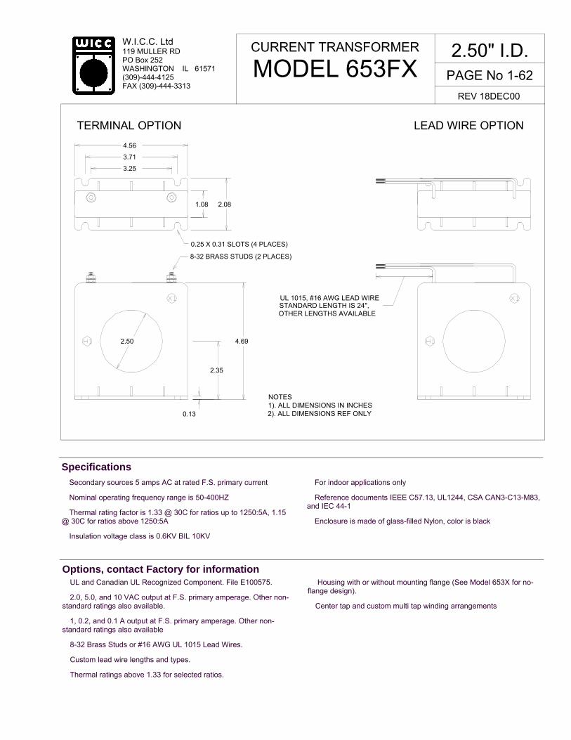
W.I.C.C. Ltd 119 MULLER RD PO Box 252 WASHINGTON IL 61571 (309)-444-4125 FAX (309)-444-3313
� Secondary sources 5 amps AC at rated F.S. primary current
� Nominal operating frequency range is 50-400HZ
� Thermal rating factor is 1.33 @ 30C for ratios up to 1250:5A, 1.15 @ 30C for ratios above 1250:5A
� Insulation voltage class is 0.6KV BIL 10KV
� For indoor applications only
� Reference documents IEEE C57.13, UL1244, CSA CAN3-C13-M83, and IEC 44-1
� Enclosure is made of glass-filled Nylon, color is black
Specifications
CURRENT TRANSFORMER
MODEL 653FX 2.50" I.D.
REV 18DEC00
� UL and Canadian UL Recognized Component. File E100575.
� 2.0, 5.0, and 10 VAC output at F.S. primary amperage. Other non-standard ratings also available.
� 1, 0.2, and 0.1 A output at F.S. primary amperage. Other non-standard ratings also available
� 8-32 Brass Studs or #16 AWG UL 1015 Lead Wires.
� Custom lead wire lengths and types.
� Thermal ratings above 1.33 for selected ratios.
� Housing with or without mounting flange (See Model 653X for no-flange design).
� Center tap and custom multi tap winding arrangements
Options, contact Factory for information
OTHER LENGTHS AVAILABLE
TERMINAL OPTION LEAD WIRE OPTION
STANDARD LENGTH IS 24",
3.25
3.71
4.56
1.08 2.08
0.13
2.35
4.692.50
0.25 X 0.31 SLOTS (4 PLACES)
8-32 BRASS STUDS (2 PLACES)
UL 1015, #16 AWG LEAD WIRE
NOTES1). ALL DIMENSIONS IN INCHES2). ALL DIMENSIONS REF ONLY
PAGE No 1-62

W.I.C.C. Ltd 119 MULLER RD PO Box 252 WASHINGTON IL 61571 (309)-444-4125 FAX (309)-444-3313
TYPICAL EXCITATION CURVE for WICC MODEL 653FX at 60HZ
10-3
10-2
10-1
100
101
102
IND
UC
ED
VO
LT
AG
E (
volt)
10-4
10-3
10-2
10-1
100
101
EXCITING CURRENT (amp)
CURRENT TRANSFORMER
MODEL 653FX 2.50" I.D.
REV 18DEC00
* "xxx" describes termination: "T" FOR BRASS STUDS, "Lyyy" FOR LEAD WIRES (Where "yyy" is the lead length in inches. For example, "L24" represents 24 inch long lead wires.)
W.I.C.C. PART NUMBER *
RATIO
ACCURACY @ 60HZ
± % BURDEN (VA)
NOMINAL WINDING RESISTANCE (ohm)
653FX-100-00-xxx 653FX-150-00-xxx 653FX-200-00-xxx 653FX-250-00-xxx 653FX-300-00-xxx 653FX-400-00-xxx 653FX-500-00-xxx 653FX-600-00-xxx 653FX-800-00-xxx
653FX-1000-00-xxx 653FX-1200-00-xxx 653FX-1600-00-xxx
100:5A 150:5A 200:5A 250:5A 300:5A 400:5A 500:5A 600:5A 800:5A 1000:5A 1200:5A 1600:5A
2.0 1.0 1.0 1.0 1.0 1.0 1.0 1.0 1.0 1.0 1.0 1.0
2.0 2.0 4.0 7.5 10 15 30 45 35 50 60 80
0.02 0.03 0.03 0.04 0.05 0.11 0.13 0.16 0.19 0.23 0.28 0.38
100:
5A
150:
5A
200:
5A
250:
5A
300:
5A
400:
5A
500:
5A
600:
5A
800:
5A
1000
:5A
1200
:5A
1600
:5A
PAGE No 1-63

W.I.C.C. Ltd 119 MULLER RD PO Box 252 WASHINGTON IL 61571 (309)-444-4125 FAX (309)-444-3313
PAGE No 1-64
� Secondary sources 1 amps AC at rated F.S. primary current
� Nominal operating frequency range is 50-400HZ
� Thermal rating factor is 1.33 @ 30C for all ratios
� Insulation voltage class is 0.6KV BIL 10KV
� For indoor applications only
� Reference documents IEEE C57.13, UL1244, CSA CAN3-C13-M83, and IEC 44-1
� Fully potted construction. Cup material is DAP, resin is UL94 VO , color is black
Specifications
� 2.0, 5.0, and 10 VAC output at F.S. primary amperage. Other non-standard ratings also available.
� 1.0 and 0.2 A output at F.S. primary amperage. Other non-standard ratings also available
� Custom lead wire lengths and types
� Thermal ratings above 1.33 for selected ratios.
� Center tap and custom multi tap winding arrangements
Options, contact Factory for information
CURRENT TRANSFORMER
MODEL 1306 0.53" I.D.
REV 18DEC00
0.53
UL 1015 #18 AWG LEAD WIRE,
NOTES:1) ALL DIMENSIONS IN INCHES2) ALL DIMENSIONS REF ONLY
0.84
1.81
1.81
0.91
STANDARD LENGTH IS 24"
POLARITY LABEL

PAGE No 1-65
W.I.C.C. Ltd 119 MULLER RD PO Box 252 WASHINGTON IL 61571 (309)-444-4125 FAX (309)-444-3313
10-5 10-4 10-2 10-1 10010-3
EXCITING CURRENT (amp)
10 -3
10 -2
10 -1
100
101
102
IND
UC
ED
VO
LT
AG
E (
volt)
TYPICAL EXCITATION CURVE for WICC MODEL 1306 at 60HZ
W.I.C.C. PART NUMBER *
RATIO
ACCURACY @ 60HZ, pf = 0.95
± % BURDEN (ohm)
NOMINAL WINDING RESISTANCE (ohm)
1306-010-02-Lxxx 1306-025-02-Lxxx 1306-050-02-Lxxx 1306-100-02-Lxxx 1306-150-02-Lxxx
10:0.1A 25:0.1A 50:0.1A
100:0.1A 150:0.1A
2.5 1.0 1.0 1.0 1.0
4.0 10 40
150 150
0.45 1.8 14 36 41
CURRENT TRANSFORMER
MODEL 1306 0.53" I.D.
REV 18DEC00
10:0
.1A
25:0
.1A
150:
0.1A
100:
0.1A
50
:0.1
A
* "Lxxx" describes LEAD WIRE termination where "xxx" is the lead length in inches. For example, "L24" represents 24 inch long lead wires.

W.I.C.C. Ltd 119 MULLER RD PO Box 252 WASHINGTON IL 61571 (309)-444-4125 FAX (309)-444-3313
PAGE No 1-66
� Secondary sources 5 amps AC at rated F.S. primary current
� Nominal operating frequency range is 50-400HZ
� Thermal rating factor is 1.33 @ 30C for all ratios
� Insulation voltage class is 0.6KV BIL 10KV
� For indoor applications only
� Reference documents IEEE C57.13, UL1244, CSA CAN3-C13-M83, and IEC 44-1
� Enclosure is glass-filled nylon, color is black
Specifications
� UL and Canadian UL Recognized Component. File E100575 � 2.0, 5.0, and 10 VAC output at F.S. primary amperage. Other non-standard ratings also available.
� 1.0, 0.2, and 0.1 A output at F.S. primary amperage. Other non-standard ratings also available
� Thermal ratings above 1.33 for selected ratios.
Options, contact Factory for information
CURRENT TRANSFORMER
MODEL 2559 1.10" I.D.
REV 18DEC00
X1
H11.10
NOTE:
1) ALL DIMENSIONS IN INCHES2) ALL DIMENSIONS REF ONLY
0.27 x 0.31 SLOT (4 PLACES)
1.00
1.13
1.75
2.40
8-32 BRASS STUD (2 PLACES)
2.00
0.16
1.25
2.70

PAGE No 1-67
W.I.C.C. Ltd 119 MULLER RD PO Box 252 WASHINGTON IL 61571 (309)-444-4125 FAX (309)-444-3313
10-4
10-3
10-2
10-1
100
101
EXCITING CURRENT (amp)
10-4
10-3
10-2
10-1
100
101
IND
UC
ED
VO
LT
AG
E (
volt)
TYPICAL EXCITATION CURVE for WICC MODEL 2559 at 60HZ
W.I.C.C. PART NUMBER *
RATIO
ACCURACY @ 60HZ, pf = 0.95
± % BURDEN (VA)
NOMINAL WINDING RESISTANCE (ohm)
2559-050-00-xxx 2559-060-00-xxx 2559-075-00-xxx 2559-100-00-xxx 2559-125-00-xxx 2559-150-00-xxx 2559-200-00-xxx 2559-250-00-xxx 2559-300-00-xxx 2559-400-00-xxx
50:5A 60:5A 75:5A
100:5A 125:5A 150:5A 200:5A 250:5A 300:5A 400:5A
3.0 2.0 2.0 1.0 1.0 1.0 1.0 1.0 1.0 1.0
2.0 2.0 2.0 2.0 2.5 4.0 5.0 7.5 10 15
0.007 0.008 0.01 0.02 0.025 0.03 0.04 0.052 0.062 0.083
CURRENT TRANSFORMER
MODEL 2559 1.10" I.D.
REV 18DEC00
50:5
A
* "xxx" describes termination: "T" FOR BRASS STUDS, "Lyyy" FOR LEAD WIRES (Where "yyy" is the lead length in inches. For example, "L24" represents 24 inch long lead wires.)
60:5
A
75:5
A 10
0:5A
125:
5A
150:
5A
250:
5A
200:
5A
300:
5A
400:
5A

W.I.C.C. Ltd 119 MULLER RD PO Box 252 WASHINGTON IL 61571 (309)-444-4125 FAX (309)-444-3313
PAGE No 1-68
� Secondary sources 5 amps AC at rated F.S. primary current
� Nominal operating frequency range is 50-400HZ
� Thermal rating factor is 1.33 @ 30C for ratios thru 1000:5A, 1.15 @ 30C for ratios above 1000:5A
� Insulation voltage class is 0.6KV BIL 10KV
� For indoor applications only
� Reference documents IEEE C57.13, UL1244, CSA CAN3-C13-M83, and IEC 44-1
� Enclosure is glass-filled nylon, color is black
Specifications
� UL and Canadian UL Recognized Component. File E100575 � 2.0, 5.0, and 10 VAC output at F.S. primary amperage. Other non-standard ratings also available.
� 1.0, 0.2, and 0.1 A output at F.S. primary amperage. Other non-standard ratings also available
� Thermal ratings above 1.33 for selected ratios.
Options, contact Factory for information
CURRENT TRANSFORMER
MODEL 2560 1.56" I.D.
REV 18DEC00
X1
H1
NOTE:1) ALL DIMENSIONS IN INCHES2) ALL DIMENSIONS REF ONLY
2.78
2.16
2.50
1.83
0.16
3.781.56
1.14
3.56
0.27 x 0.33 SLOT (4 PLACES)
8-32 BRASS STUD (2 PLACES)

PAGE No 1-69
W.I.C.C. Ltd 119 MULLER RD PO Box 252 WASHINGTON IL 61571 (309)-444-4125 FAX (309)-444-3313
10-3
10-2
10-1
100
101
102
IND
UC
ED
VO
LT
AG
E (
volt)
10-4
10-3
10-2
10-1
100
101
EXCITING CURRENT (amp)
TYPICAL EXCITATION CURVE for WICC MODEL 2560 at 60HZ
W.I.C.C. PART NUMBER *
RATIO
ACCURACY @ 60HZ, pf = 0.95
± % BURDEN (VA)
NOMINAL WINDING RESISTANCE (ohm)
2560-050-00-xxx 2560-100-00-xxx 2560-200-00-xxx 2560-250-00-xxx 2560-300-00-xxx 2560-400-00-xxx 2560-500-00-xxx 2560-600-00-xxx 2560-800-00-xxx
2560-1000-00-xxx 2560-1200-00-xxx
50:5A 100:5A 200:5A 250:5A 300:5A 400:5A 500:5A 600:5A 800:5A 1000:5A 1200:5A
3.0 1.0 1.0 1.0 1.0 1.0 1.0 1.0 1.0 1.0 1.0
2.0 2.0 7.5 12 20 30 45 35 50 60 75
0.01 0.02 0.06 0.07 0.09 0.11 0.14 0.14 0.19 0.24 0.37
CURRENT TRANSFORMER
MODEL 2560 1.56" I.D.
REV 18DEC00
100:
5A
* "xxx" describes termination: "T" FOR BRASS STUDS, "Lyyy" FOR LEAD WIRES (Where "yyy" is the lead length in inches. For example, "L24" represents 24 inch long lead wires.)
200:
5A
300:
5A
400:
5A
500:
5A
1200
:5A
800:
5A
1000
:5A

W.I.C.C. Ltd 119 MULLER RD PO Box 252 WASHINGTON IL 61571 (309)-444-4125 FAX (309)-444-3313
PAGE No 1-70
� Secondary sources 5 amps AC at rated F.S. primary current
� Nominal operating frequency range is 50-400HZ
� Thermal rating factor is 1.33 @ 30C for ratios thru 1000:5A, 1.15 @ 30C for ratios above 1000:5A � Insulation voltage class is 0.6KV BIL 10KV
� For indoor applications only
� Reference documents IEEE C57.13, UL1244, CSA CAN3-C13-M83, and IEC 44-1
� Enclosure is made of glass-filled Nylon, color is black
Specifications
� UL and Canadian UL Recognized Component. File E100575.
� 2.0, 5.0, and 10 VAC output at F.S. primary amperage. Other non-standard ratings also available.
� 1, 0.2, and 0.1 A output at F.S. primary amperage. Other non-standard ratings also available.
� Thermal ratings above 1.33 for selected ratios
Options, contact Factory for information
CURRENT TRANSFORMER
MODEL 2562 2.06" I.D.
REV 18DEC00
X1
H1
NOTE:1) ALL DIMENSIONS IN INCHES2) ALL DIMENSIONS REF ONLY
2.81
2.13
4.15
2.13
0.16
4.272.06
1.13
0.27 x 0.31 SLOT (4 PLACES)
3.35
8-32 BRASS STUD (2 PLACES)

PAGE No 1-71
W.I.C.C. Ltd 119 MULLER RD PO Box 252 WASHINGTON IL 61571 (309)-444-4125 FAX (309)-444-3313
TYPICAL EXCITATION CURVE for WICC MODEL 2562 at 60HZ
10-3
10-2
10-1
100
101
102
IND
UC
ED
VO
LT
AG
E (
volt)
10-4 10-3 10-2 10-1 100 101
EXCITATION CURRENT (amp)
* "xxx" describes termination: "T" FOR BRASS STUDS, "Lyyy" FOR LEAD WIRES (Where "yyy" is the lead length in inches. For example, "L24" represents 24 inch long lead wires.)
W.I.C.C. PART NUMBER *
RATIO
ACCURACY @ 60HZ
± % BURDEN (VA)
NOMINAL WINDING RESISTANCE (ohm)
2562-100-00-xxx 2562-150-00-xxx 2562-200-00-xxx 2562-300-00-xxx 2562-400-00-xxx 2562-500-00-xxx 2562-600-00-xxx 2562-800-00-xxx
2562-1000-00-xxx 2562-1200-00-xxx 2562-1500-00-xxx
100:5A 150:5A 200:5A 300:5A 400:5A 500:5A 600:5A 800:5A 1000:5A 1200:5A 1500:5A
2.0 1.0 1.0 1.0 1.0 1.0 1.0 1.0 1.0 1.0 1.0
2.0 2.0 5.0 12 25 35 50 70 80 60 85
0.03 0.05 0.06 0.08 0.11 0.13 0.16 0.21 0.27 0.31 0.44
CURRENT TRANSFORMER
MODEL 2562 2.06" I.D.
REV 18DEC00
100:
5A
200:
5A 40
0:5A
300:
5A 50
0:5A
600:
5A
800:
5A
1000
:5A
1500
:5A

W.I.C.C. Ltd 119 MULLER RD PO Box 252 WASHINGTON IL 61571 (309)-444-4125 FAX (309)-444-3313
PAGE No 1-72
� Secondary sources 0.1 amps AC at rated F.S. primary current
� Nominal operating frequency range is 50-400HZ
� Thermal rating factor is 1.33 @ 30C for all ratios
� Insulation voltage class is 0.6KV BIL 10KV
� For indoor applications only
� Reference documents IEEE C57.13, UL1244, CSA CAN3-C13-M83, and IEC 44-1
� Fully potted construction. Cup material is DAP, resin is UL94 VO , color is black
� Lead wire is #18 nylon-clad PVC, 600V, 115C, MIL-W-16878/17
Specifications
� 1.0, 2.0, and 5.0 VAC output at F.S. primary amperage. Other non-standard ratings also available.
� 0.2 A output at F.S. primary amperage. Other non-standard ratings also available
� Custom lead wire lengths and types
� Thermal ratings above 1.33 for selected ratios.
Options, contact Factory for information
CURRENT TRANSFORMER
MODEL 2638 0.38" I.D.
REV 18DEC00
Ø1.33POLARITY LABEL
0.75
NYLON-CLAD PVC #18 LEADWIRE, STANDARD LENGTH IS 24"
Ø0.38
NOTES:1). ALL DIMENSIONS IN INCHES2). ALL DIMENSIONS REF ONLY

PAGE No 1-73
W.I.C.C. Ltd 119 MULLER RD PO Box 252 WASHINGTON IL 61571 (309)-444-4125 FAX (309)-444-3313
10-6
10-5
10-4
10-3
10-2
10-1
EXCITING CURRENT (amp)
TYPICAL EXCITATION CURVE for WICC MODEL 2638 at 60HZ
10-3
10-2
10-1
100
101
102
IND
UC
ED
VO
LT
AG
E (
volt)
W.I.C.C. PART NUMBER *
RATIO
ACCURACY @ 60HZ, pf = 0.95
± % BURDEN (ohm)
NOMINAL WINDING RESISTANCE (ohm)
2638-010-02-Lxxx 2638-025-02-Lxxx 2638-050-02-Lxxx 2638-100-02-Lxxx 2638-150-02-Lxxx
10:0.1A 25:0.1A 50:0.1A
100:0.1A 150:0.1A
2.5 1.0 1.0 1.0 1.0
1 3 15 70
150
1 5 9
24 46
CURRENT TRANSFORMER
MODEL 2638 0.38" I.D.
REV 18DEC00
10:0
.1A
25:0
.1A
150:
0.1A
100:
0.1A
50:0
.1A
* "Lxxx" describes LEAD WIRE termination where "xxx" is the lead length in inches. For example, "L24" represents 24 inch long lead wires.

W.I.C.C. Ltd 119 MULLER RD PO Box 252 WASHINGTON IL 61571 (309)-444-4125 FAX (309)-444-3313
PAGE No 1-74
� Secondary sources 5 amps AC at rated F.S. primary current
� Nominal operating frequency range is 50-400HZ
� Thermal rating factor is 1.33 @ 30C for ratios thru 1000:5A, 1.15 @ 30C for ratios above 1000:5A � Insulation voltage class is 0.6KV BIL 10KV
� For indoor applications only
� Reference documents IEEE C57.13, UL1244, CSA CAN3-C13-M83, and IEC 44-1
� Enclosure is made of glass-filled Nylon, color is black
Specifications
� UL and Canadian UL Recognized Component. File E100575.
� 2.0, 5.0, and 10 VAC output at F.S. primary amperage. Other non-standard ratings also available.
� 1, 0.2, and 0.1 A output at F.S. primary amperage. Other non-standard ratings also available.
� Thermal ratings above 1.33 for selected ratios
Options, contact Factory for information
CURRENT TRANSFORMER
MODEL 2743 2.06" I.D.
REV 18DEC00
X1
H1
NOTE:1) ALL DIMENSIONS IN INCHES2) ALL DIMENSIONS REF ONLY
2.81
2.13
4.15
2.13
0.16
4.272.06
1.13
0.27 x 0.31 SLOT (4 PLACES)
3.35
8-32 BRASS STUD (2 PLACES)
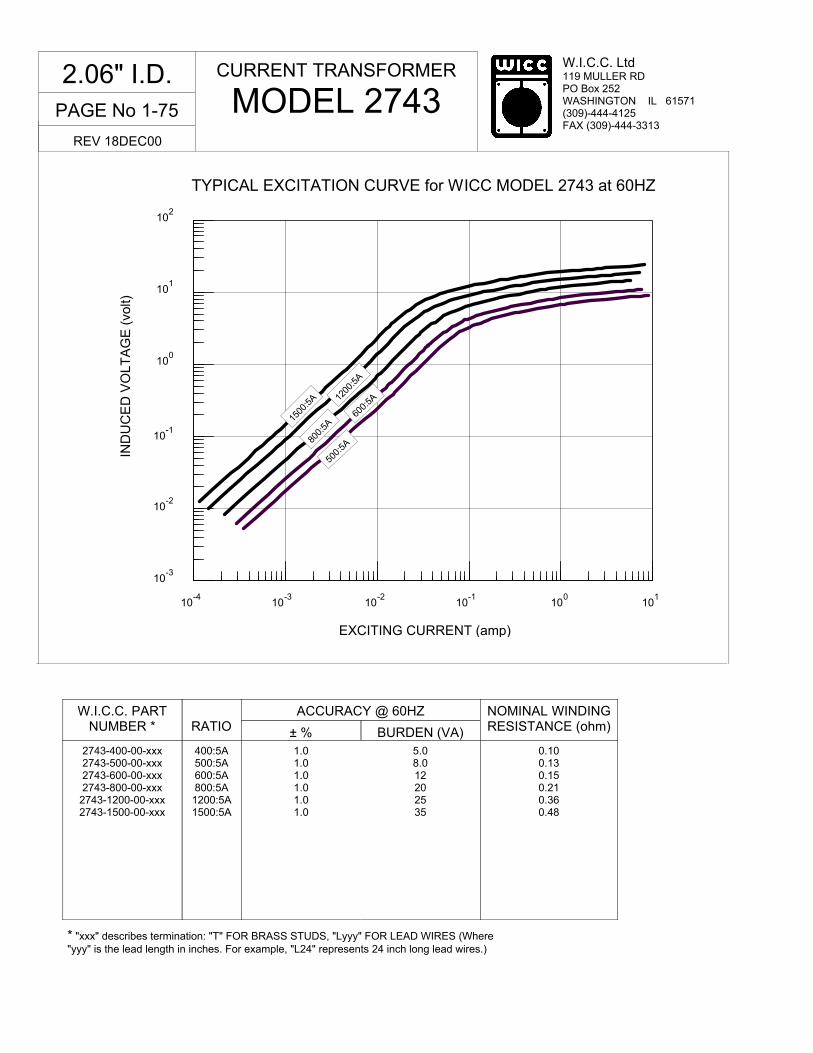
PAGE No 1-75
W.I.C.C. Ltd 119 MULLER RD PO Box 252 WASHINGTON IL 61571 (309)-444-4125 FAX (309)-444-3313
10-4
10-3
10-2
100
101
10-1
EXCITING CURRENT (amp)
10-3
10-2
10-1
100
101
102
IND
UC
ED
VO
LT
AG
E (
volt)
TYPICAL EXCITATION CURVE for WICC MODEL 2743 at 60HZ
* "xxx" describes termination: "T" FOR BRASS STUDS, "Lyyy" FOR LEAD WIRES (Where "yyy" is the lead length in inches. For example, "L24" represents 24 inch long lead wires.)
W.I.C.C. PART NUMBER *
RATIO
ACCURACY @ 60HZ
± % BURDEN (VA)
NOMINAL WINDING RESISTANCE (ohm)
2743-400-00-xxx 2743-500-00-xxx 2743-600-00-xxx 2743-800-00-xxx
2743-1200-00-xxx 2743-1500-00-xxx
400:5A 500:5A 600:5A 800:5A 1200:5A 1500:5A
1.0 1.0 1.0 1.0 1.0 1.0
5.0 8.0 12 20 25 35
0.10 0.13 0.15 0.21 0.36 0.48
CURRENT TRANSFORMER
MODEL 2743 2.06" I.D.
REV 18DEC00
500:
5A 80
0:5A
600:
5A 12
00:5
A
1500
:5A

W.I.C.C. Ltd 119 MULLER RD PO Box 252 WASHINGTON IL 61571 (309)-444-4125 FAX (309)-444-3313
PAGE No 2-0
Large Frame Current Transformers... For measuring 50-400HZ currents in bus bar and other large conductor systems. Typical configuration is 400A to 12000A primary current with secondary of 1A or 5A (special secondary currents are also available). W.I.C.C. manufactures designs having inside areas as small as 3.00” x 7.00” and as large as 7.00” x 27.00” and 10.00” x 24.00”. All models are available with optional mounting plates for "bulk-head" mounting. Some models are U.L. Recognized devices.
REV 14DEC00
Model J1 ………………………….2-2 Model J3 ………………………….2-4 Model J5 ………………………….2-6 Model J6 ………………………….2-8 Model J7/21 ……………………..2-10 Model J7/25 ……………………..2-12 Model J7/27 ……………………..2-14 Model J10/24 ……………………2-16
Table of Contents

PAGE No 2-1
W.I.C.C. Ltd 119 MULLER RD PO Box 252 WASHINGTON IL 61571 (309)-444-4125 FAX (309)-444-3313
BLANK PAGE

W.I.C.C. Ltd 119 MULLER RD PO Box 252 WASHINGTON IL 61571 (309)-444-4125 FAX (309)-444-3313
PAGE No 2-2
CURRENT TRANSFORMER
MODEL J1 3" x 7"
REV 18DEC00
� Secondary sources 5 amps AC at rated F.S. primary current
� Nominal operating frequency range is 50-400HZ
� Thermal rating factor is 1.33 @ 30C for all ratios
� Insulation voltage class is 0.6KV BIL 10KV
� For indoor applications only
� Reference documents IEEE C57.13, UL1244, CSA CAN3-C13-M83, and IEC 44-1
� Enclosure is multi-layer tape buildup with heavy vinyl finish, color is black
� Optional plate is XX phenolic
� UL and Canadian UL Recognized Component. File E100575
Specifications
� 2.0, 5.0, and 10 VAC output at F.S. primary amperage. Other non-standard ratings also available.
� 1, 0.2, and 0.1 A output at F.S. primary amperage. Other non-standard ratings also available
� 8-32 Screw Terminals or #16 AWG UL 1015 Lead Wires
� Custom lead wire lengths and types
� Thermal ratings above 1.33 for selected ratios.
� Available with BB4 bus bar brackets. See Bracket Data Section for dimensions.
Options, contact Factory for information
TERMINAL OPTION
4 5
3
7
9 316
8
9
5 516
OPTIONAL MOUNTING PLATE BONDED TO TRANSFORMER
Ø 932 (4 PLACES)
8-32 BRASS SCREW TERMINALS(2 PLACES)
X1
H1 H1
LEAD WIRE OPTION
STANDARD LENGTH IS 24"UL 1015 #16 AWG LEAD WIRE,
2). ALL DIMENSIONS REF ONLY1). ALL DIMENSIONS IN INCHESNOTES
316
SEE NOTE 3
3). HT = 1-1/2 FOR RATIOS UP TO 1750:5A HT = 1-3/8 FOR RATIOS 1750:5A to 3000:5A HT = 1-1/8 FOR RATIOS ABOVE 3000:5A
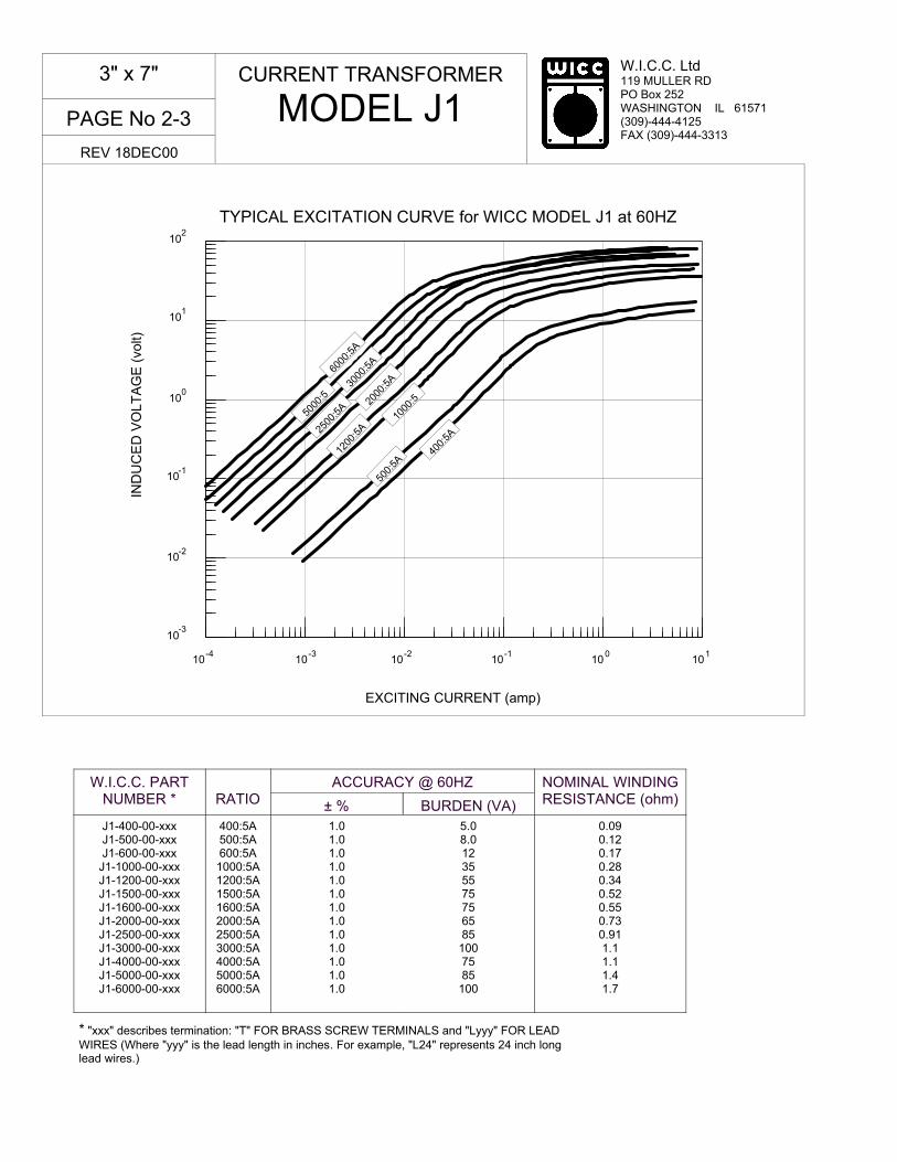
PAGE No 2-3
W.I.C.C. Ltd 119 MULLER RD PO Box 252 WASHINGTON IL 61571 (309)-444-4125 FAX (309)-444-3313
10-4
10-3
10-2
10-1
100
101
EXCITING CURRENT (amp)
TYPICAL EXCITATION CURVE for WICC MODEL J1 at 60HZ
10-3
10-2
10-1
100
101
102
IND
UC
ED
VO
LT
AG
E (
volt)
* "xxx" describes termination: "T" FOR BRASS SCREW TERMINALS and "Lyyy" FOR LEAD WIRES (Where "yyy" is the lead length in inches. For example, "L24" represents 24 inch long lead wires.)
W.I.C.C. PART NUMBER *
RATIO
ACCURACY @ 60HZ
± % BURDEN (VA)
NOMINAL WINDING RESISTANCE (ohm)
J1-400-00-xxx J1-500-00-xxx J1-600-00-xxx
J1-1000-00-xxx J1-1200-00-xxx J1-1500-00-xxx J1-1600-00-xxx J1-2000-00-xxx J1-2500-00-xxx J1-3000-00-xxx J1-4000-00-xxx J1-5000-00-xxx J1-6000-00-xxx
400:5A 500:5A 600:5A 1000:5A 1200:5A 1500:5A 1600:5A 2000:5A 2500:5A 3000:5A 4000:5A 5000:5A 6000:5A
1.0 1.0 1.0 1.0 1.0 1.0 1.0 1.0 1.0 1.0 1.0 1.0 1.0
5.0 8.0 12 35 55 75 75 65 85
100 75 85
100
0.09 0.12 0.17 0.28 0.34 0.52 0.55 0.73 0.91 1.1 1.1 1.4 1.7
CURRENT TRANSFORMER
MODEL J1 3" x 7"
REV 18DEC00
400:
5A
500:
5A 12
00:5
A 20
00:5
A
2500
:5A
3000
:5A
5000
:5
6000
:5A
1000
:5

W.I.C.C. Ltd 119 MULLER RD PO Box 252 WASHINGTON IL 61571 (309)-444-4125 FAX (309)-444-3313
PAGE No 2-4
CURRENT TRANSFORMER
MODEL J3 3-1/4" x 11-3/4"
REV 18DEC00
� Secondary sources 5 amps AC at rated F.S. primary current
� Nominal operating frequency range is 50-400HZ
� Thermal rating factor is 1.33 @ 30C for all ratios
� Insulation voltage class is 0.6KV BIL 10KV
� For indoor applications only
� Reference documents IEEE C57.13, UL1244, CSA CAN3-C13-M83, and IEC 44-1
� Enclosure is multi-layer tape buildup with heavy vinyl finish, color is black
� Optional plate is XX phenolic
Specifications
� 2.0, 5.0, and 10 VAC output at F.S. primary amperage. Other non-standard ratings also available.
� 1 A output at F.S. primary amperage. Other non-standard ratings also available
� Thermal ratings above 1.33 for selected ratios
� 8-32 Screw Terminals or #16 AWG UL 1015 Lead Wires
� Custom lead wire lengths and types
� Available with B71 bus bar brackets. See Bracket Data Section for dimensions.
Options, contact Factory for information
8-32 BRASS SCREW TERMINAL(2 PLACES)
X1
H1
2). ALL DIMENSIONS REF ONLY1). ALL DIMENSIONS IN INCHESNOTES
11-3/4
3-1/4
1-1/4
316
1312
1412
5 6
OPTIONAL MOUNTING PLATEBONDED TOTRANSFORMER
Ø 932 (4 PLACES)

PAGE No 2-5
W.I.C.C. Ltd 119 MULLER RD PO Box 252 WASHINGTON IL 61571 (309)-444-4125 FAX (309)-444-3313
10-4
10-3
10-2
10-1
100
101
EXCITING CURRENT (amp)
10-2
10-1
100
101
102
103
IND
UC
ED
VO
LT
AG
E (
volt)
TYPICAL EXCITATION CURVE for WICC MODEL J3 at 60HZ
W.I.C.C. PART NUMBER *
RATIO
ACCURACY @ 60HZ
± % BURDEN (VA)
NOMINAL WINDING RESISTANCE (ohm)
J3-500-00-xxx J3-1000-00-xxx J3-1200-00-xxx J3-1500-00-xxx J3-2000-00-xxx J3-2500-00-xxx J3-3000-00-xxx J3-4000-00-xxx J3-5000-00-xxx J3-6000-00-xxx J3-8000-00-xxx
500:5A 1000:5A 1200:5A 1500:5A 2000:5A 2500:5A 3000:5A 4000:5A 5000:5A 6000:5A 8000:5A
1.0 1.0 1.0 1.0 1.0 1.0 1.0 1.0 1.0 1.0 1.0
3.5 15 20 40 75
100 100 100 100 100 100
0.10 0.32 0.37 0.46 0.61 0.76 0.91 1.3 1.6 2.0 2.7
CURRENT TRANSFORMER
MODEL J3 3-1/4" x 11-3/4"
REV 18DEC00
1500
:5A
500:
5A
1200
:5A
2000
:5A
2500
:5A
3000
:5A
5000
:5A
6000
:5
1000
:5
4000
:5
8000
:5A
* "xxx" describes termination: "T" FOR BRASS SCREW TERMINALS and "Lyyy" FOR LEAD WIRES (Where "yyy" is the lead length in inches. For example, "L24" represents 24 inch long lead wires.)

W.I.C.C. Ltd 119 MULLER RD PO Box 252 WASHINGTON IL 61571 (309)-444-4125 FAX (309)-444-3313
PAGE No 2-6
CURRENT TRANSFORMER
MODEL J5 3-1/2" x 14-3/4"
REV 18DEC00
� Secondary sources 5 amps AC at rated F.S. primary current
� Nominal operating frequency range is 50-400HZ
� Thermal rating factor is 1.33 @ 30C for all ratios
� Insulation voltage class is 0.6KV BIL 10KV
� For indoor applications only
� Reference documents IEEE C57.13, UL1244, CSA CAN3-C13-M83, and IEC 44-1
� Enclosure is multi-layer tape buildup with heavy vinyl finish, color is black
� Optional plate is XX phenolic
Specifications
� 2.0, 5.0, and 10 VAC output at F.S. primary amperage. Other non-standard ratings also available.
� 1 A output at F.S. primary amperage. Other non-standard ratings also available
� Thermal ratings above 1.33 for selected ratios
� 8-32 Screw Terminals or #16 AWG UL 1015 Lead Wires
� Custom lead wire lengths and types
Options, contact Factory for information
1614
5
8-32 BRASS SCREW TERMINAL(2 PLACES)
1714
114
316
6
OPTIONAL MOUNTING PLATEBONDED TO TRANSFORMER
NOTES:1.)ALL DIMENSIONS IN INCHES2.)ALL DIMENSIONS REF ONLY
Ø14
(4 PLACES)
X1
H1
312
1434

PAGE No 2-7
W.I.C.C. Ltd 119 MULLER RD PO Box 252 WASHINGTON IL 61571 (309)-444-4125 FAX (309)-444-3313
W.I.C.C. PART NUMBER *
RATIO
ACCURACY @ 60HZ
± % BURDEN (VA)
NOMINAL WINDING RESISTANCE (ohm)
J3-2000-00-xxx J3-3000-00-xxx J3-4000-00-xxx J3-5000-00-xxx J3-6000-00-xxx J3-7000-00-xxx J3-9000-00-xxx
J3-10000-00-xxx
2000:5A 3000:5A 4000:5A 5000:5A 6000:5A 7000:5A 9000:5A
10000:5A
1.0 1.0 1.0 1.0 1.0 1.0 1.0 1.0
65 100 100 100 100 100 100 100
0.60 0.95 1.20 1.50 1.90 2.10 2.60 3.32
CURRENT TRANSFORMER
MODEL J5 3-1/2" x 14-3/4"
REV 18DEC00
* "xxx" describes termination: "T" FOR BRASS SCREW TERMINALS and "Lyyy" FOR LEAD WIRES (Where "yyy" is the lead length in inches. For example, "L24" represents 24 inch long lead wires.)
TYPICAL EXCITATION CURVE FOR WICC MODEL J5 at 60HZ
10-2
10-1
100
101
102
103
IND
UC
ED
VO
LT
AG
E (
volt)
10-4
10-3
10-2
10-1
100
101
EXCITING CURRENT (amp)
1000
0:5A
9000
:5A
7000
:5A 60
00:5
A
5000
:5A
4000
:5A
3000
:5A
2000
:5A

W.I.C.C. Ltd 119 MULLER RD PO Box 252 WASHINGTON IL 61571 (309)-444-4125 FAX (309)-444-3313
PAGE No 2-8
CURRENT TRANSFORMER
MODEL J6 3" x 18-1/4"
REV 18DEC00
� Secondary sources 5 amps AC at rated F.S. primary current
� Nominal operating frequency range is 50-400HZ
� Thermal rating factor is 1.33 @ 30C for all ratios
� Insulation voltage class is 0.6KV BIL 10KV
� For indoor applications only
� Reference documents IEEE C57.13, UL1244, CSA CAN3-C13-M83, and IEC 44-1
� Enclosure is multi-layer tape buildup with heavy vinyl finish, color is black
� Optional plate is XX phenolic
Specifications
� 2.0, 5.0, and 10 VAC output at F.S. primary amperage. Other non-standard ratings also available.
� 1 A output at F.S. primary amperage. Other non-standard ratings also available
� Thermal ratings above 1.33 for selected ratios
� 8-32 Screw Terminals or #16 AWG UL 1015 Lead Wires
� Custom lead wire lengths and types
Options, contact Factory for information
8-32 BRASS SCREW TERMINAL (2 PLACES)
NOTES:1.) ALL DIMENSIONS IN INCHES2.) ALL DIMENSIONS REF ONLY
OPTIONAL MOUNTING PLATEBONDED TO TRANSFORMER
3
X1
H1
1814 51
8418
1934
2034
14
114
Ø14 (4 PLACES)

PAGE No 2-9
W.I.C.C. Ltd 119 MULLER RD PO Box 252 WASHINGTON IL 61571 (309)-444-4125 FAX (309)-444-3313
TYPICAL EXCITATION CURVE FOR WICC MODEL J6 at 60HZ
10-4
10-3
10-2
10-1
100
101
EXCITING CURRENT (amp)
10-1
100
101
102
103
IND
UC
ED
VO
LT
AG
E (
volt)
W.I.C.C. PART NUMBER *
RATIO
ACCURACY @ 60HZ
± % BURDEN (VA)
NOMINAL WINDING RESISTANCE (ohm)
J6-4000-00-xxx J6-5000-00-xxx J6-6000-00-xxx J6-8000-00-xxx
4000:5A 5000:5A 6000:5A 8000:5A
1.0 1.0 1.0 1.0
100 100 100 100
1.21 1.54 1.87 2.53
CURRENT TRANSFORMER
MODEL J6 3" x 18-1/4"
REV 18DEC00
* "xxx" describes termination: "T" FOR BRASS SCREW TERMINALS and "Lyyy" FOR LEAD WIRES (Where "yyy" is the lead length in inches. For example, "L24" represents 24 inch long lead wires.)
8000
:5A
5000
:5A
4000
:5A
6000
:5A
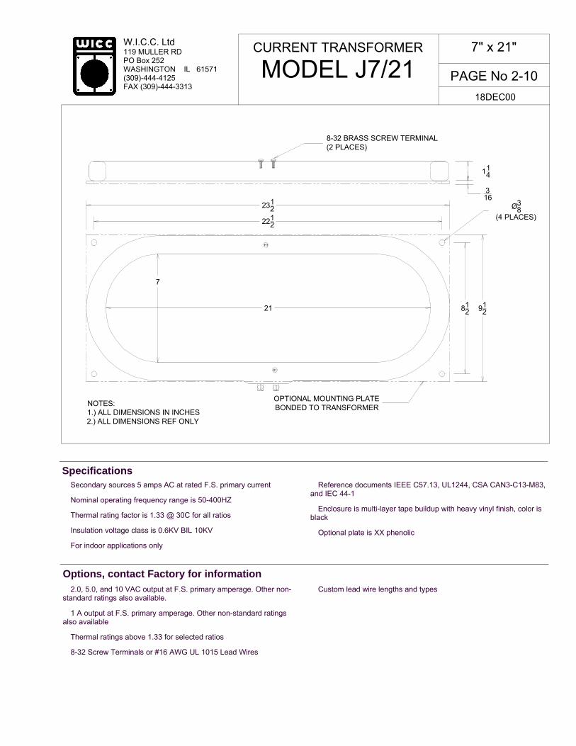
W.I.C.C. Ltd 119 MULLER RD PO Box 252 WASHINGTON IL 61571 (309)-444-4125 FAX (309)-444-3313
PAGE No 2-10
CURRENT TRANSFORMER
MODEL J7/21 7" x 21"
18DEC00
� Secondary sources 5 amps AC at rated F.S. primary current
� Nominal operating frequency range is 50-400HZ
� Thermal rating factor is 1.33 @ 30C for all ratios
� Insulation voltage class is 0.6KV BIL 10KV
� For indoor applications only
� Reference documents IEEE C57.13, UL1244, CSA CAN3-C13-M83, and IEC 44-1
� Enclosure is multi-layer tape buildup with heavy vinyl finish, color is black
� Optional plate is XX phenolic
Specifications
� 2.0, 5.0, and 10 VAC output at F.S. primary amperage. Other non-standard ratings also available.
� 1 A output at F.S. primary amperage. Other non-standard ratings also available
� Thermal ratings above 1.33 for selected ratios
� 8-32 Screw Terminals or #16 AWG UL 1015 Lead Wires
� Custom lead wire lengths and types
Options, contact Factory for information
2212
812
114
X1
H1
OPTIONAL MOUNTING PLATE BONDED TO TRANSFORMER
NOTES:1.) ALL DIMENSIONS IN INCHES2.) ALL DIMENSIONS REF ONLY
8-32 BRASS SCREW TERMINAL (2 PLACES)
316
2312
21
7
912
Ø38
(4 PLACES)

PAGE No 2-11
W.I.C.C. Ltd 119 MULLER RD PO Box 252 WASHINGTON IL 61571 (309)-444-4125 FAX (309)-444-3313
TYPICAL EXCITATION CURVE FOR WICC MODEL J7/21 at 60HZ
10-4 10-3 10-2 10-1 100 101
EXCITING CURRENT (amp)
10-2
10-1
100
101
102
103
IND
UC
ED
VO
LT
AG
E (
volt)
W.I.C.C. PART NUMBER *
RATIO
ACCURACY @ 60HZ
± % BURDEN (VA)
NOMINAL WINDING RESISTANCE (ohm)
J7/21-1000-00-xxx J7/21-2000-00-xxx J7/21-3000-00-xxx J7/21-4000-00-xxx J7/21-5000-00-xxx J7/21-6000-00-xxx J7/21-8000-00-xxx J7/21-1200-00-xxx
1000:5A 2000:5A 3000:5A 4000:5A 5000:5A 6000:5A 8000:5A
12000:5A
1.0 1.0 1.0 1.0 1.0 1.0 1.0 1.0
6 40
100 100 100 100 100 100
0.31 0.60 0.91 1.21 1.51 1.84 2.50 3.90
CURRENT TRANSFORMER
MODEL J7/21 7" x 21"
REV 18DEC00
12000
:5A
8000
:5A
2000
:5A
3000
:5A
5000
:5A
1000
:5A
4000
:5A
6000
:5A
* "xxx" describes termination: "T" FOR BRASS SCREW TERMINALS and "Lyyy" FOR LEAD WIRES (Where "yyy" is the lead length in inches. For example, "L24" represents 24 inch long lead wires.)

W.I.C.C. Ltd 119 MULLER RD PO Box 252 WASHINGTON IL 61571 (309)-444-4125 FAX (309)-444-3313
PAGE No 2-12
CURRENT TRANSFORMER
MODEL J7/25 7" x 25"
REV 18DEC00
� Secondary sources 5 amps AC at rated F.S. primary current
� Nominal operating frequency range is 50-400HZ
� Thermal rating factor is 1.33 @ 30C for all ratios
� Insulation voltage class is 0.6KV BIL 10KV
� For indoor applications only
� Reference documents IEEE C57.13, UL1244, CSA CAN3-C13-M83, and IEC 44-1
� Enclosure is multi-layer tape buildup with heavy vinyl finish, color is black
� Optional plate is XX phenolic
Specifications
� 2.0, 5.0, and 10 VAC output at F.S. primary amperage. Other non-standard ratings also available.
� 1, 0.2, and 0.1 A output at F.S. primary amperage. Other non-standard ratings also available
� 8-32 Screw Terminals or #16 AWG UL 1015 Lead Wires
� Custom lead wire lengths and types
� Thermal ratings above 1.33 for selected ratios.
Options, contact Factory for information
25
7
2712
912
Ø38
(4 PLACES)
114
2612
812
OPTIONAL MOUNTING PLATEBONDED TO TRANSFORMERNOTES:
1.) ALL DIMENSIONS IN INCHES2.) ALL DIMENSIONS REF ONLY
8-32 BRASS SCREW TERMINAL(2 PLACES)
H1
X1
316

PAGE No 2-13
W.I.C.C. Ltd 119 MULLER RD PO Box 252 WASHINGTON IL 61571 (309)-444-4125 FAX (309)-444-3313
TYPICAL EXCITATION CURVE FOR WICC MODEL J7/25 at 60HZ
10-2
10-1
100
101
102
103
IND
UC
ED
VO
LT
AG
E (
volt)
10-4
10-3
10-2
10-1
100
101
EXCITING CURRENT (amp)
* "xxx" describes termination: "T" FOR BRASS SCREW TERMINALS and "Lyyy" FOR LEAD WIRES (Where "yyy" is the lead length in inches. For example, "L24" represents 24 inch long lead wires.)
W.I.C.C. PART NUMBER *
RATIO
ACCURACY @ 60HZ
± % BURDEN (VA)
NOMINAL WINDING RESISTANCE (ohm)
J7/25-1000-00-xxx J7/25-1600-00-xxx J7/25-2000-00-xxx J7/25-2400-00-xxx J7/25-5000-00-xxx
2000:5A 1600:5A 2000:5A 2400:5A 5000:5A
1.0 1.0 1.0 1.0 1.0
6.0 20 35 50
100
0.35 0.50 0.60 0.75 1.50
CURRENT TRANSFORMER
MODEL J7/25 7" x 25"
REV 18DEC00
1000
:5A
1600
:5A
2000
:5A
2400
:5A
5000
:5A

W.I.C.C. Ltd 119 MULLER RD PO Box 252 WASHINGTON IL 61571 (309)-444-4125 FAX (309)-444-3313
PAGE No 2-14
CURRENT TRANSFORMER
MODEL J7/27 7" x 27"
REV 18DEC00
� Secondary sources 5 amps AC at rated F.S. primary current
� Nominal operating frequency range is 50-400HZ
� Thermal rating factor is 1.33 @ 30C for all ratios
� Insulation voltage class is 0.6KV BIL 10KV
� For indoor applications only
� Reference documents IEEE C57.13, UL1244, CSA CAN3-C13-M83, and IEC 44-1
� Enclosure is multi-layer tape buildup with heavy vinyl finish, color is black
� Optional plate is XX phenolic
Specifications
� 2.0, 5.0, and 10 VAC output at F.S. primary amperage. Other non-standard ratings also available.
� 1, 0.2, and 0.1 A output at F.S. primary amperage. Other non-standard ratings also available
� 8-32 Screw Terminals or #16 AWG UL 1015 Lead Wires
� Custom lead wire lengths and types
� Thermal ratings above 1.33 for selected ratios.
Options, contact Factory for information
27
7
2912
2812
114
316
Ø38
(4 PLACES)
H1
X1
8-32 BRASS SCREW TERMINAL(2 PLACES)
OPTIONAL MOUNTING PLATEBONDED TO TRANSFORMERNOTES:
1.) ALL DIMENSIONS IN INCHES2.) ALL DIMENSIONS REF ONLY
91281
2

PAGE No 2-15
W.I.C.C. Ltd 119 MULLER RD PO Box 252 WASHINGTON IL 61571 (309)-444-4125 FAX (309)-444-3313
TYPICAL EXCITATION CURVE FOR WICC MODEL J7/27 at 60HZ
10-4
10-3
10-2
10-1
100
101
EXCITING CURRENT (amp)
10-2
10-1
100
101
102
103
IND
UC
ED
VO
LT
AG
E (
volt)
* "xxx" describes termination: "T" FOR BRASS SCREW TERMINALS and "Lyyy" FOR LEAD WIRES (Where "yyy" is the lead length in inches. For example, "L24" represents 24 inch long lead wires.)
W.I.C.C. PART NUMBER *
RATIO
ACCURACY @ 60HZ
± % BURDEN (VA)
NOMINAL WINDING RESISTANCE (ohm)
J7/27-2000-00-xxx J7/27-2500-00-xxx J7/27-4000-00-xxx
2000:5A 2500:5A 4000:5A
1.0 1.0 1.0
30 55
100
0.60 0.75 1.21
CURRENT TRANSFORMER
MODEL J7/27 7" x 27"
REV 18DEC00
4000
:5A
2000
:5A
2500
:5A

W.I.C.C. Ltd 119 MULLER RD PO Box 252 WASHINGTON IL 61571 (309)-444-4125 FAX (309)-444-3313
PAGE No 2-16
CURRENT TRANSFORMER
MODEL J10/24 10" x 24"
REV 18DEC00
� Secondary sources 5 amps AC at rated F.S. primary current
� Nominal operating frequency range is 50-400HZ
� Thermal rating factor is 1.33 @ 30C for all ratios
� Insulation voltage class is 0.6KV BIL 10KV
� For indoor applications only
� Reference documents IEEE C57.13, UL1244, CSA CAN3-C13-M83, and IEC 44-1
� Enclosure is multi-layer tape buildup with heavy vinyl finish, color is black
� Optional plate is XX phenolic
Specifications
� 2.0, 5.0, and 10 VAC output at F.S. primary amperage. Other non-standard ratings also available.
� 1, 0.2, and 0.1 A output at F.S. primary amperage. Other non-standard ratings also available
� 8-32 Screw Terminals or #16 AWG UL 1015 Lead Wires
� Custom lead wire lengths and types
� Thermal ratings above 1.33 for selected ratios.
Options, contact Factory for information
8-32 BRASS SCREW TERMINAL (2 PLACES)
H1
X1
OPTIONAL MOUNTING PLATE BONDED TO TRANSFORMER
NOTES:1.) ALL DIMENSIONS IN INCHES2.) ALL DIMENSIONS REF ONLY
2634
2534
24
10
Ø38
(4 PLACES)
114
316
1212111
2

PAGE No 2-17
W.I.C.C. Ltd 119 MULLER RD PO Box 252 WASHINGTON IL 61571 (309)-444-4125 FAX (309)-444-3313
10-2
10-1
100
101
102
103
IND
UC
ED
VO
LT
AG
E (
volt)
10-4
10-3
10-2
10-1
100
101
EXCITING CURRENT (amp)
TYPICAL EXCITATION CURVE FOR WICC MODEL J10/24 at 60HZ
* "xxx" describes termination: "T" FOR BRASS SCREW TERMINALS and "Lyyy" FOR LEAD WIRES (Where "yyy" is the lead length in inches. For example, "L24" represents 24 inch long lead wires.)
W.I.C.C. PART NUMBER *
RATIO
ACCURACY @ 60HZ
± % BURDEN (VA)
NOMINAL WINDING RESISTANCE (ohm)
J10/24-2000-00-xxx J10/24-3000-00-xxx
2000:5A 3000:5A
1.0 1.0
30 85
0.60 0.91
CURRENT TRANSFORMER
MODEL J10/24 10" x 24"
REV 18DEC00
2000
:5A
3000
:5A

W.I.C.C. Ltd 119 MULLER RD PO Box 252 WASHINGTON IL 61571 (309)-444-4125 FAX (309)-444-3313
PAGE No 3-0
Split-Core Current Transformers ... This type of current transformer is available to measure AC currents from 100A to 6000A, at 50 to 400HZ. They are very popular in sub-metering applications where existing systems are being upgraded and it is impractical to isolate the primary conductor. It is even possible to install this type of transformer while the conductor is energized, however it is paramount that certain safety precautions be followed under such conditions. Rectangular in shape, standard split-core models are available with window dimensions up to 4.00" x 7.50". Even larger, custom designed sizes are available by special order. Secondary ratings of 5A, 1A, and 100mA are all common in split-core current transformers. Two model groups are available, SP and SPS. The former is provided with a stainless steel screw-clamp band securing the two core halves, the latter has a UV resistant nylon band. All ratios are available in either type. Electrical and magnetic performance is identical for the two groups.
REV 22SEP00
Model 1SP ................................. 3-2 Model 2SP ................................. 3-4 Model 3SP ................................. 3-6 Model 5SP ................................. 3-8 Model 7SP ............................... 3-10 Model 9SP ............................... 3-12 Model 91SP ............................. 3-14
Table of Contents

PAGE No 3-1
W.I.C.C. Ltd 119 MULLER RD PO Box 252 WASHINGTON IL 61571 (309)-444-4125 FAX (309)-444-3313
BLANK PAGE

W.I.C.C. Ltd 119 MULLER RD PO Box 252 WASHINGTON IL 61571 (309)-444-4125 FAX (309)-444-3313
PAGE No 3-2
� Secondary sources 5 amps AC at rated F.S. primary current
� Nominal operating frequency range is 50-400HZ
� Thermal rating factor is 1.33 @ 30C for all ratios
� Insulation voltage class is 0.6KV BIL 10KV
� For indoor applications only
� Reference documents C57.13, UL 1244, CSA CAN3-C13-M83, and IEC 44-1
� CT can be split apart and reassembled onto the primary conductor without interrupting service. NOTE: Safety precautions must be observed
� CT is finished in heavy vinyl tape with dipped acrylic overcoat. Uses imbedded SS band to secure two halves of transformer together
Specifications
� UV resistant Nylon band to secure two halves of transformer together (1SPS model)
� Reversed polarity, BLK lead wire is made X1
� 1, 0.2, and 0.1 A output at F.S. primary amperage. Other non-standard ratings also available
� 8-32 screw terminals
� Custom lead wire lengths and types
� Thermal ratings above 1.33 for selected ratios
Options, contact Factory for information
SPLIT CORE CURRENT TRANSFORMER
MODEL 1SP
0.84" x 2.00"
REV 18DEC00
A = 0.84 MIN B = 2.00 MIN C = 3.31 MAX D = 3.09 MAX E = 0.61 MAX F = 1.00 MAX
NOTES: 1). ALL DIMENSIONS ARE IN INCHES 2). ALL DIMENSIONS ARE REF ONLY 3). ALL DIMENSIONS ARE MEASURED OVER THE HIGHEST POINT OF THE APPROPRIATE SURFACE. 4). WHITE LEAD WIRE IS ELECTRICALLY IN PHASE WITH “H1” SIDE OF TRANSFROMER (with polarity marks) 5). CAUTION-POTENTIALLY LETHAL VOLTAGES MAY APPEAR ON TERMINALS IF NOT ELECTRICALLY CONNECTED TOGETHER WHEN INSTALLING ON TO AN ENERGIZED SYSTEM. IT IS IMPERATIVE THAT LEADS and/or TERMINALS BE SHORTED TOGETHER OR ATTACHED TO THE INTENDED BURDEN PRIOR TO SUCH INSTALLATON.
UL 1015 LEAD WIRE, STANDARD LENGTH IS 36”
DIMENSIONS
B
E
C
D F
A

PAGE No 3-3
W.I.C.C. Ltd 119 MULLER RD PO Box 252 WASHINGTON IL 61571 (309)-444-4125 FAX (309)-444-3313
TYPICAL EXCITATION CURVE for WICC MODEL 1SP at 60HZ
10-4
10-3
10-2
10-1
100
IND
UC
ED
VO
LT
AG
E (
volt)
101
10-4
10-3
10-2
10-1
100
EXCITING CURRENT (amp)
101
* "xxx" describes termination: "T" FOR SCREW TERMINALS, "Lyyy" FOR LEAD WIRES (Where "yyy" is the lead length in inches. For example, "L24" represents 24 inch long lead wires.)
W.I.C.C. PART NUMBER *
RATIO
ACCURACY @ 60HZ
± % BURDEN (VA)
NOMINAL WINDING RESISTANCE (ohm)
1SP-100-00-xxx 1SP-200-00-xxx 1SP-300-00-xxx 1SP-400-00-xxx
100:5A 200:5A 300:5A 400:5A
3.0 1.0 1.0 1.0
1.0 1.5 2.0 5.0
0.02 0.03 0.08 0.12
SPLIT CORE CURRENT TRANSFORMER
MODEL 1SP
0.84" x 2.00"
REV 18DEC00
100:
5A
200:
5A 40
0:5A
300:
5A
NOTE ON ACCURACY: Because of the inherent design of this type of current transformer, accuracy is defined, in part, by the care with which the user installs the device. It is imperative that absolute cleanliness of the core mating surfaces be maintained during installation. Accuracy listed is verified at time of shipment and, with proper installation, should be realizable in the field.
LEAD WIRE SIZE (AWG)
12 14 16 16

W.I.C.C. Ltd 119 MULLER RD PO Box 252 WASHINGTON IL 61571 (309)-444-4125 FAX (309)-444-3313
PAGE No 3-4
� Secondary sources 5 amps AC at rated F.S. primary current
� Nominal operating frequency range is 50-400HZ
� Thermal rating factor is 1.33 @ 30C for all ratios
� Insulation voltage class is 0.6KV BIL 10KV
� For indoor applications only
� Reference documents C57.13, UL 1244, CSA CAN3-C13-M83, and IEC 44-1
� CT can be split apart and reassembled onto the primary conductor without interrupting service. NOTE: Safety precautions must be observed
� CT is finished in heavy vinyl tape with dipped acrylic overcoat. Uses imbedded SS band to secure two halves of transformer together
Specifications
� UV resistant Nylon band to secure two halves of transformer together (2SPS model)
� Reversed polarity, BLK lead wire is made X1
� 1, 0.2, and 0.1 A output at F.S. primary amperage. Other non-standard ratings also available
� 8-32 screw terminals
� Custom lead wire lengths and types
� Thermal ratings above 1.33 for selected ratios
Options, contact Factory for information
SPLIT CORE CURRENT TRANSFORMER
MODEL 2SP
0.90" x 2.13"
REV 18DEC00
A = 0.90 MIN B = 2.13 MIN C = 4.13 MAX D = 4.0 MAX E = 0.50MAX F = 1.50 MAX
NOTES: 1). ALL DIMENSIONS ARE IN INCHES 2). ALL DIMENSIONS ARE REF ONLY 3). ALL DIMENSIONS ARE MEASURED OVER THE HIGHEST POINT OF THE APPROPRIATE SURFACE. 4). WHITE LEAD WIRE IS ELECTRICALLY IN PHASE WITH “H1” SIDE OF TRANSFROMER (with polarity marks) 5). CAUTION-POTENTIALLY LETHAL VOLTAGES MAY APPEAR ON TERMINALS IF NOT ELECTRICALLY CONNECTED TOGETHER WHEN INSTALLING ON TO AN ENERGIZED SYSTEM. IT IS IMPERATIVE THAT LEADS and/or TERMINALS BE SHORTED TOGETHER OR ATTACHED TO THE INTENDED BURDEN PRIOR TO SUCH INSTALLATON.
UL 1015 LEAD WIRE, STANDARD LENGTH IS 36”
B
E
C
D F
A
DIMENSIONS
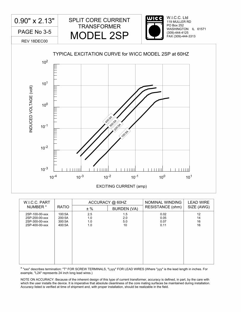
PAGE No 3-5
W.I.C.C. Ltd 119 MULLER RD PO Box 252 WASHINGTON IL 61571 (309)-444-4125 FAX (309)-444-3313
10-3
10-2
10-1
100
101
102
IND
UC
ED
VO
LT
AG
E (
volt)
TYPICAL EXCITATION CURVE for WICC MODEL 2SP at 60HZ
10-4 10-3 10-2 10-1 100 101
EXCITING CURRENT (amp)
* "xxx" describes termination: "T" FOR SCREW TERMINALS, "Lyyy" FOR LEAD WIRES (Where "yyy" is the lead length in inches. For example, "L24" represents 24 inch long lead wires.)
W.I.C.C. PART NUMBER *
RATIO
ACCURACY @ 60HZ
± % BURDEN (VA)
NOMINAL WINDING RESISTANCE (ohm)
2SP-100-00-xxx 2SP-200-00-xxx 2SP-300-00-xxx 2SP-400-00-xxx
100:5A 200:5A 300:5A 400:5A
2.5 1.0 1.0 1.0
1.5 2.0 5.0 10
0.02 0.05 0.07 0.11
SPLIT CORE CURRENT TRANSFORMER
MODEL 2SP
0.90" x 2.13"
REV 18DEC00
100:
5A 20
0:5A
400:
5A
300:
5A
NOTE ON ACCURACY: Because of the inherent design of this type of current transformer, accuracy is defined, in part, by the care with which the user installs the device. It is imperative that absolute cleanliness of the core mating surfaces be maintained during installation. Accuracy listed is verified at time of shipment and, with proper installation, should be realizable in the field.
LEAD WIRE SIZE (AWG)
12 14 16 16

W.I.C.C. Ltd 119 MULLER RD PO Box 252 WASHINGTON IL 61571 (309)-444-4125 FAX (309)-444-3313
PAGE No 3-6
� Secondary sources 5 amps AC at rated F.S. primary current
� Nominal operating frequency range is 50-400HZ
� Thermal rating factor is 1.33 @ 30C for all ratios
� Insulation voltage class is 0.6KV BIL 10KV
� For indoor applications only
� Reference documents C57.13, UL 1244, CSA CAN3-C13-M83, and IEC 44-1
� CT can be split apart and reassembled onto the primary conductor without interrupting service. NOTE: Safety precautions must be observed
� CT is finished in heavy vinyl tape with dipped acrylic overcoat. Uses imbedded SS band to secure two halves of transformer together
Specifications
� UV resistant Nylon band to secure two halves of transformer together (3SPS model)
� Reversed polarity, BLK lead wire is made X1
� 1, 0.2, and 0.1 A output at F.S. primary amperage. Other non-standard ratings also available
� 8-32 screw terminals
� Custom lead wire lengths and types
� Thermal ratings above 1.33 for selected ratios
Options, contact Factory for information
SPLIT CORE CURRENT TRANSFORMER
MODEL 3SP
2.19" x 3.25"
REV 18DEC00
A = 2.19 MIN B = 3.25 MIN C = 4.56 MAX D = 4.72 MAX E = 0.61 MAX F = 1.14 MAX
NOTES: 1). ALL DIMENSIONS ARE IN INCHES 2). ALL DIMENSIONS ARE REF ONLY 3). ALL DIMENSIONS ARE MEASURED OVER THE HIGHEST POINT OF THE APPROPRIATE SURFACE. 4). WHITE LEAD WIRE IS ELECTRICALLY IN PHASE WITH “H1” SIDE OF TRANSFROMER (with polarity marks) 5). CAUTION-POTENTIALLY LETHAL VOLTAGES MAY APPEAR ON TERMINALS IF NOT ELECTRICALLY CONNECTED TOGETHER WHEN INSTALLING ON TO AN ENERGIZED SYSTEM. IT IS IMPERATIVE THAT LEADS and/or TERMINALS BE SHORTED TOGETHER OR ATTACHED TO THE INTENDED BURDEN PRIOR TO SUCH INSTALLATON.
UL 1015 LEAD WIRE, STANDARD LENGTH IS 36”
B
E
C
D F
A
DIMENSIONS

PAGE No 3-7
W.I.C.C. Ltd 119 MULLER RD PO Box 252 WASHINGTON IL 61571 (309)-444-4125 FAX (309)-444-3313
TYPICAL EXCITATION CURVE for WICC MODEL 3SP at 60HZ
10-4
10-3
10-2
10-1
100
101
EXCITING CURRENT (amp)
10-3
10-2
10-1
100
101
102
IND
UC
ED
VO
LT
AG
E (
volt)
* "xxx" describes termination: "T" FOR SCREW TERMINALS, "Lyyy" FOR LEAD WIRES (Where "yyy" is the lead length in inches. For example, "L24" represents 24 inch long lead wires.)
W.I.C.C. PART NUMBER *
RATIO
ACCURACY @ 60HZ
± % BURDEN (VA)
NOMINAL WINDING RESISTANCE (ohm)
3SP-200-00-xxx 3SP-300-00-xxx 3SP-400-00-xxx 3SP-500-00-xxx 3SP-600-00-xxx
3SP-1000-00-xxx 3SP-1200-00-xxx
200:5A 300:5A 400:5A 500:5A 600:5A 1000:5A 1200:5A
1.5 1.0 1.0 1.0 1.0 1.0 1.0
1.0 1.0 2.0 3.0 5.0 20 30
0.03 0.08 0.10 0.16 0.20 0.34 0.50
SPLIT CORE CURRENT TRANSFORMER
MODEL 3SP
2.19" x 3.25"
REV 18DEC00
500:
5A
200:
5A
600:
5A 30
0:5A
NOTE ON ACCURACY: Because of the inherent design of this type of current transformer, accuracy is defined, in part, by the care with which the user installs the device. It is imperative that absolute cleanliness of the core mating surfaces be maintained during installation. Accuracy listed is verified at time of shipment and, with proper installation, should be realizable in the field.
LEAD WIRE SIZE (AWG)
14 16 16 16 16 16 16
400:
5A
1000
:5A
1200
:5A

W.I.C.C. Ltd 119 MULLER RD PO Box 252 WASHINGTON IL 61571 (309)-444-4125 FAX (309)-444-3313
PAGE No 3-8
� Secondary sources 5 amps AC at rated F.S. primary current
� Nominal operating frequency range is 50-400HZ
� Thermal rating factor is 1.33 @ 30C for all ratios
� Insulation voltage class is 0.6KV BIL 10KV
� For indoor applications only
� Reference documents C57.13, UL 1244, CSA CAN3-C13-M83, and IEC 44-1
� CT can be split apart and reassembled onto the primary conductor without interrupting service. NOTE: Safety precautions must be observed
� CT is finished in heavy vinyl tape with dipped acrylic overcoat. Uses imbedded SS band to secure two halves of transformer together
Specifications
� UV resistant Nylon band to secure two halves of transformer together (5SPS model)
� Reversed polarity, BLK lead wire is made X1
� 1, 0.2, and 0.1 A output at F.S. primary amperage. Other non-standard ratings also available
� 8-32 screw terminals
� Custom lead wire lengths and types
� Thermal ratings above 1.33 for selected ratios
Options, contact Factory for information
SPLIT CORE CURRENT TRANSFORMER
MODEL 5SP
2.88" x 4.25"
REV 19DEC00
A = 2.88 MIN B = 4.25 MIN C = 5.56 MAX D = 5.69 MAX E = 0.61 MAX F = 1.14 MAX
NOTES: 1). ALL DIMENSIONS ARE IN INCHES 2). ALL DIMENSIONS ARE REF ONLY 3). ALL DIMENSIONS ARE MEASURED OVER THE HIGHEST POINT OF THE APPROPRIATE SURFACE. 4). WHITE LEAD WIRE IS ELECTRICALLY IN PHASE WITH “H1” SIDE OF TRANSFROMER (with polarity marks) 5). CAUTION-POTENTIALLY LETHAL VOLTAGES MAY APPEAR ON TERMINALS IF NOT ELECTRICALLY CONNECTED TOGETHER WHEN INSTALLING ON TO AN ENERGIZED SYSTEM. IT IS IMPERATIVE THAT LEADS and/or TERMINALS BE SHORTED TOGETHER OR ATTACHED TO THE INTENDED BURDEN PRIOR TO SUCH INSTALLATON.
UL 1015 LEAD WIRE, STANDARD LENGTH IS 36”
B
E
C
D F
A
DIMENSIONS

PAGE No 3-9
W.I.C.C. Ltd 119 MULLER RD PO Box 252 WASHINGTON IL 61571 (309)-444-4125 FAX (309)-444-3313
TYPICAL EXCITATION CURVE for WICC MODEL 5SP at 60HZ
10-3
10-2
10-1
100
101
102
IND
UC
ED
VO
LT
AG
E (
volt)
10-4
10-3
10-2
10-1
100
101
EXCITING CURRENT (amp)
* "xxx" describes termination: "T" FOR SCREW TERMINALS, "Lyyy" FOR LEAD WIRES (Where "yyy" is the lead length in inches. For example, "L24" represents 24 inch long lead wires.)
W.I.C.C. PART NUMBER *
RATIO
ACCURACY @ 60HZ
± % BURDEN (VA)
NOMINAL WINDING RESISTANCE (ohm)
5SP-300-00-xxx 5SP-500-00-xxx 5SP-600-00-xxx 5SP-800-00-xxx
5SP-1000-00-xxx 5SP-1200-00-xxx 5SP-1500-00-xxx 5SP-2000-00-xxx
300:5A 500:5A 600:5A 800:5A 1000:5A 1200:5A 1500:5A 2000:5A
1.5 1.0 1.0 1.0 1.0 1.0 1.0 1.0
1.0 2.0 3.0 10 15 25 35 50
0.08 0.17 0.20 0.27 0.34 0.40 0.50 0.67
SPLIT CORE CURRENT TRANSFORMER
MODEL 5SP
2.88" x 4.25"
REV 19DEC00
600:
5A
2000
:5A
300:
5A
NOTE ON ACCURACY: Because of the inherent design of this type of current transformer, accuracy is defined, in part, by the care with which the user installs the device. It is imperative that absolute cleanliness of the core mating surfaces be maintained during installation. Accuracy listed is verified at time of shipment and, with proper installation, should be realizable in the field.
LEAD WIRE SIZE (AWG)
16 16 16 16 16 16 16 16
500:
5A
800:
5A
1000
:5A
1200
:5A
1500
:5A

W.I.C.C. Ltd 119 MULLER RD PO Box 252 WASHINGTON IL 61571 (309)-444-4125 FAX (309)-444-3313
PAGE No 3-10
� Secondary sources 5 amps AC at rated F.S. primary current
� Nominal operating frequency range is 50-400HZ
� Thermal rating factor is 1.33 @ 30C for all ratios
� Insulation voltage class is 0.6KV BIL 10KV
� For indoor applications only
� Reference documents C57.13, UL 1244, CSA CAN3-C13-M83, and IEC 44-1
� CT can be split apart and reassembled onto the primary conductor without interrupting service. NOTE: Safety precautions must be observed
� CT is finished in heavy vinyl tape with dipped acrylic overcoat. Uses imbedded SS band to secure two halves of transformer together
Specifications
� UV resistant Nylon band to secure two halves of transformer together (7SPS model)
� Reversed polarity, BLK lead wire is made X1
� 1, 0.2, and 0.1 A output at F.S. primary amperage. Other non-standard ratings also available
� 8-32 screw terminals
� Custom lead wire lengths and types
� Thermal ratings above 1.33 for selected ratios
Options, contact Factory for information
SPLIT CORE CURRENT TRANSFORMER
MODEL 7SP
2.88" x 6.25"
REV 19DEC00
A = 2.88 MIN B = 6.25 MIN C = 7.63 MAX D = 5.63 MAX E = 0.61 MAX F = 1.14 MAX
NOTES: 1). ALL DIMENSIONS ARE IN INCHES 2). ALL DIMENSIONS ARE REF ONLY 3). ALL DIMENSIONS ARE MEASURED OVER THE HIGHEST POINT OF THE APPROPRIATE SURFACE. 4). WHITE LEAD WIRE IS ELECTRICALLY IN PHASE WITH “H1” SIDE OF TRANSFORMER (with polarity marks) 5). CAUTION-POTENTIALLY LETHAL VOLTAGES MAY APPEAR ON TERMINALS IF NOT ELECTRICALLY CONNECTED TOGETHER WHEN INSTALLING ON TO AN ENERGIZED SYSTEM. IT IS IMPERATIVE THAT LEADS and/or TERMINALS BE SHORTED TOGETHER OR ATTACHED TO THE INTENDED BURDEN PRIOR TO SUCH INSTALLATION.
UL 1015 LEAD WIRE STANDARD LENGTH IS 36”
B
E
C
D F
A
DIMENSIONS

PAGE No 3-11
W.I.C.C. Ltd 119 MULLER RD PO Box 252 WASHINGTON IL 61571 (309)-444-4125 FAX (309)-444-3313
10-3
10-2
10-1
100
101
102
IND
UC
ED
VO
LT
AG
E (
volt)
TYPICAL EXCITATION CURVE for WICC MODEL 7SP at 60HZ
10-4
10-3
10-2
10-1
100
101
EXCITING CURRENT (amp)
* "xxx" describes termination: "T" FOR SCREW TERMINALS, "Lyyy" FOR LEAD WIRES (Where "yyy" is the lead length in inches. For example, "L24" represents 24 inch long lead wires.)
W.I.C.C. PART NUMBER *
RATIO
ACCURACY @ 60HZ
± % BURDEN (VA)
NOMINAL WINDING RESISTANCE (ohm)
7SP-600-00-xxx 7SP-800-00-xxx
7SP-1000-00-xxx 7SP-1200-00-xxx 7SP-1500-00-xxx 7SP-2000-00-xxx 7SP-2500-00-xxx 7SP-3000-00-xxx
600:5A 800:5A 1000:5A 1200:5A 1500:5A 2000:5A 2500:5A 3000:5A
1.0 1.0 1.0 1.0 1.0 1.0 1.0 1.0
2.5 5.0 10 15 20 40 50 50
0.20 0.27 0.34 0.40 0.51 0.67 0.84 1.01
SPLIT CORE CURRENT TRANSFORMER
MODEL 7SP
2.88" x 6.25"
REV 19DEC00
1000
:5A
3000
:5A
600:
5A
NOTE ON ACCURACY: Because of the inherent design of this type of current transformer, accuracy is defined, in part, by the care with which the user installs the device. It is imperative that absolute cleanliness of the core mating surfaces be maintained during installation. Accuracy listed is verified at time of shipment and, with proper installation, should be realizable in the field.
LEAD WIRE SIZE (AWG)
16 16 16 16 16 16 16 16
800:
5A 12
00:5
A
1500
:5A
2000
:5A
2500
:5A

W.I.C.C. Ltd 119 MULLER RD PO Box 252 WASHINGTON IL 61571 (309)-444-4125 FAX (309)-444-3313
PAGE No 3-12
� Secondary sources 5 amps AC at rated F.S. primary current
� Nominal operating frequency range is 50-400HZ
� Thermal rating factor is 1.33 @ 30C for ratios up thru 7500:5A, 1.15 @ 30C for ratios of 7500:5A and above
� Insulation voltage class is 0.6KV BIL 10KV
� For indoor applications only
� Reference documents C57.13, UL 1244, CSA CAN3-C13-M83, and IEC 44-1
� CT can be split apart and reassembled onto the primary conductor without interrupting service. NOTE: Safety precautions must be observed
� CT is finished in heavy vinyl tape with dipped acrylic overcoat. Uses imbedded SS band to secure two halves of transformer together
Specifications
� UV resistant Nylon band to secure two halves of transformer together (9SPS model)
� Reversed polarity, BLK lead wire is made X1
� 1, 0.2, and 0.1 A output at F.S. primary amperage. Other non-standard ratings also available
� 8-32 screw terminals
� Custom lead wire lengths and types
� Thermal ratings above 1.33 for selected ratios
Options, contact Factory for information
SPLIT CORE CURRENT TRANSFORMER
MODEL 9SP
2.88" x 7.75"
REV 19DEC00
A = 2.88 MIN B = 7.75 MIN C = 9.13 MAX D = 5.75 MAX E = 0.61 MAX F = 1.14 MAX
NOTES: 1). ALL DIMENSIONS ARE IN INCHES 2). ALL DIMENSIONS ARE REF ONLY 3). ALL DIMENSIONS ARE MEASURED OVER THE HIGHEST POINT OF THE APPROPRIATE SURFACE. 4). WHITE LEAD WIRE IS ELECTRICALLY IN PHASE WITH “H1” SIDE OF TRANSFROMER (with polarity marks) 5). CAUTION-POTENTIALLY LETHAL VOLTAGES MAY APPEAR ON TERMINALS IF NOT ELECTRICALLY CONNECTED TOGETHER WHEN INSTALLING ON TO AN ENERGIZED SYSTEM. IT IS IMPERATIVE THAT LEADS and/or TERMINALS BE SHORTED TOGETHER OR ATTACHED TO THE IN-TENDED BURDEN PRIOR TO SUCH INSTALLATON.
UL 1015 LEAD WIRE, STANDARD LENGTH IS 36”
B
E
C
D F
A
DIMENSIONS
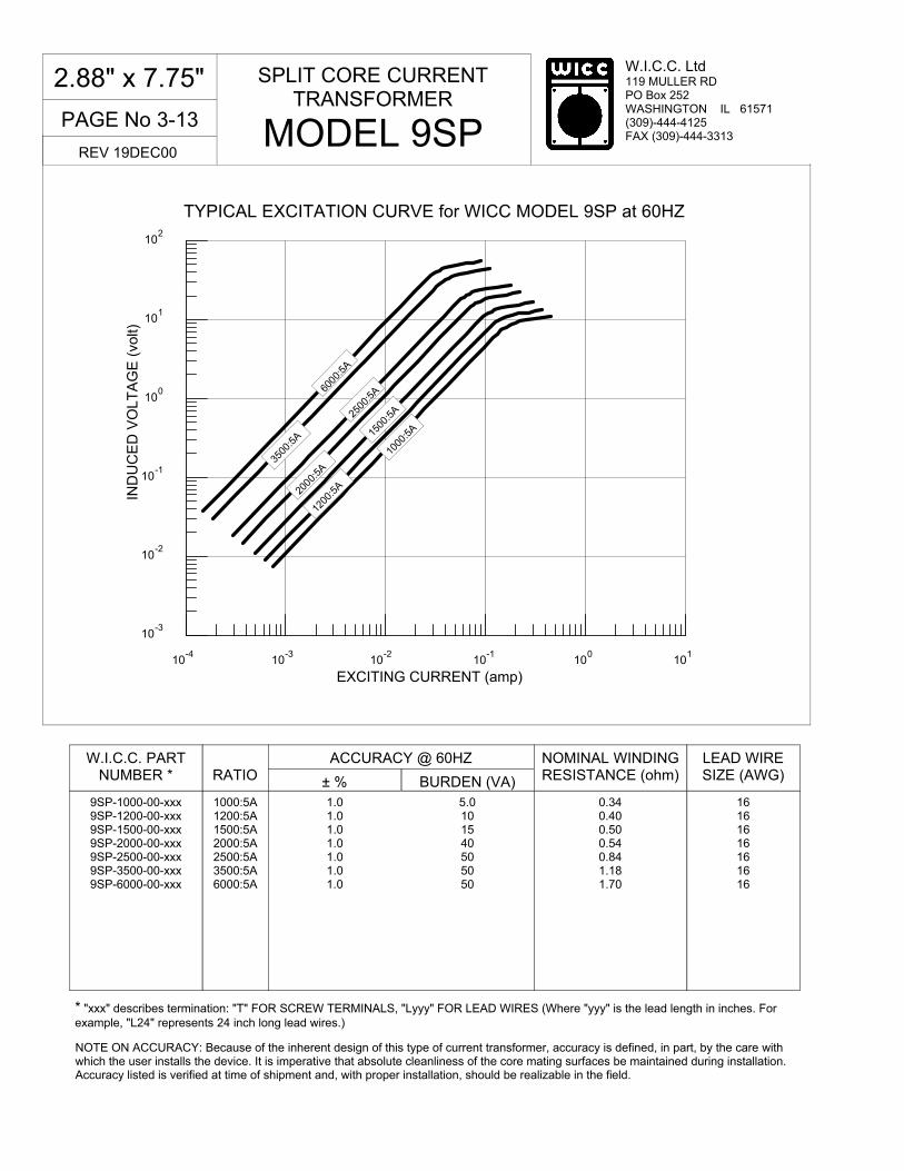
PAGE No 3-13
W.I.C.C. Ltd 119 MULLER RD PO Box 252 WASHINGTON IL 61571 (309)-444-4125 FAX (309)-444-3313
10-3
10-2
10-1
100
101
102
IND
UC
ED
VO
LT
AG
E (
volt)
TYPICAL EXCITATION CURVE for WICC MODEL 9SP at 60HZ
10-4
10-3
10-2
10-1
100
101
EXCITING CURRENT (amp)
* "xxx" describes termination: "T" FOR SCREW TERMINALS, "Lyyy" FOR LEAD WIRES (Where "yyy" is the lead length in inches. For example, "L24" represents 24 inch long lead wires.)
W.I.C.C. PART NUMBER *
RATIO
ACCURACY @ 60HZ
± % BURDEN (VA)
NOMINAL WINDING RESISTANCE (ohm)
9SP-1000-00-xxx 9SP-1200-00-xxx 9SP-1500-00-xxx 9SP-2000-00-xxx 9SP-2500-00-xxx 9SP-3500-00-xxx 9SP-6000-00-xxx
1000:5A 1200:5A 1500:5A 2000:5A 2500:5A 3500:5A 6000:5A
1.0 1.0 1.0 1.0 1.0 1.0 1.0
5.0 10 15 40 50 50 50
0.34 0.40 0.50 0.54 0.84 1.18 1.70
SPLIT CORE CURRENT TRANSFORMER
MODEL 9SP
2.88" x 7.75"
REV 19DEC00
1000
:5A
3500
:5A
NOTE ON ACCURACY: Because of the inherent design of this type of current transformer, accuracy is defined, in part, by the care with which the user installs the device. It is imperative that absolute cleanliness of the core mating surfaces be maintained during installation. Accuracy listed is verified at time of shipment and, with proper installation, should be realizable in the field.
LEAD WIRE SIZE (AWG)
16 16 16 16 16 16 16
1200
:5A
1500
:5A
6000
:5A
2500
:5A
2000
:5A

W.I.C.C. Ltd 119 MULLER RD PO Box 252 WASHINGTON IL 61571 (309)-444-4125 FAX (309)-444-3313
PAGE No 3-14
� Secondary sources 5 amps AC at rated F.S. primary current
� Nominal operating frequency range is 50-400HZ
� Thermal rating factor is 1.33 @ 30C for ratios up thru 7500:5A, 1.15 @ 30C for ratios of 7500:5A and above
� Insulation voltage class is 0.6KV BIL 10KV
� For indoor applications only
� Reference documents C57.13, UL 1244, CSA CAN3-C13-M83, and IEC 44-1
� CT can be split apart and reassembled onto the primary conductor without interrupting service. NOTE: Safety precautions must be observed
� CT is finished in heavy vinyl tape with dipped acrylic overcoat. Uses imbedded SS band to secure two halves of transformer together
Specifications
� UV resistant Nylon band to secure two halves of transformer together (91SPS model)
� Reversed polarity, BLK lead wire is made X1
� 1, 0.2, and 0.1 A output at F.S. primary amperage. Other non-standard ratings also available
� 8-32 screw terminals
� Custom lead wire lengths and types
� Thermal ratings above 1.33 for selected ratios
Options, contact Factory for information
SPLIT CORE CURRENT TRANSFORMER
MODEL 91SP
4.00" x 7.50"
REV 19DEC00
A = 4.00 MIN B = 7.50 MIN C = 9.50 MAX D = 6.88 MAX E = 0.61 MAX F = 1.14 MAX
NOTES: 1). ALL DIMENSIONS ARE IN INCHES 2). ALL DIMENSIONS ARE REF ONLY 3). ALL DIMENSIONS ARE MEASURED OVER THE HIGHEST POINT OF THE APPROPRIATE SURFACE. 4). WHITE LEAD WIRE IS ELECTRICALLY IN PHASE WITH “H1” SIDE OF TRANSFROMER (with polarity marks) 5). CAUTION-POTENTIALLY LETHAL VOLTAGES MAY APPEAR ON TERMINALS IF NOT ELECTRICALLY CONNECTED TOGETHER WHEN INSTALLING ON TO AN ENERGIZED SYSTEM. IT IS IMPERATIVE THAT LEADS and/or TERMINALS BE SHORTED TOGETHER OR ATTACHED TO THE INTENDED BURDEN PRIOR TO SUCH INSTALLATION.
UL 1015 LEAD WIRE, STANDARD LENGTH IS 36”
B
E
C
D F
A
DIMENSIONS
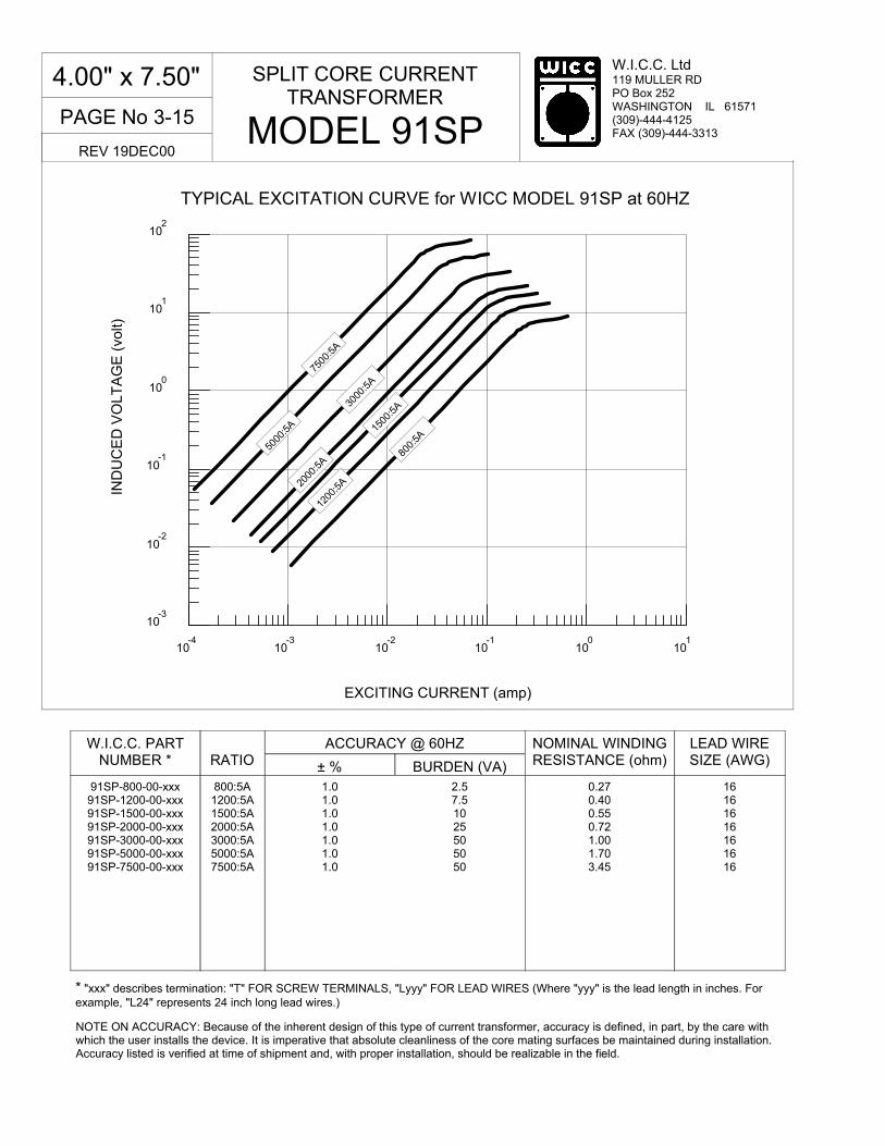
PAGE No 3-15
W.I.C.C. Ltd 119 MULLER RD PO Box 252 WASHINGTON IL 61571 (309)-444-4125 FAX (309)-444-3313
TYPICAL EXCITATION CURVE for WICC MODEL 91SP at 60HZ
10-3
10-2
10-1
100
101
102
IND
UC
ED
VO
LT
AG
E (
volt)
10-4
10-3
10-2
10-1
100
101
EXCITING CURRENT (amp)
* "xxx" describes termination: "T" FOR SCREW TERMINALS, "Lyyy" FOR LEAD WIRES (Where "yyy" is the lead length in inches. For example, "L24" represents 24 inch long lead wires.)
W.I.C.C. PART NUMBER *
RATIO
ACCURACY @ 60HZ
± % BURDEN (VA)
NOMINAL WINDING RESISTANCE (ohm)
91SP-800-00-xxx 91SP-1200-00-xxx 91SP-1500-00-xxx 91SP-2000-00-xxx 91SP-3000-00-xxx 91SP-5000-00-xxx 91SP-7500-00-xxx
800:5A 1200:5A 1500:5A 2000:5A 3000:5A 5000:5A 7500:5A
1.0 1.0 1.0 1.0 1.0 1.0 1.0
2.5 7.5 10 25 50 50 50
0.27 0.40 0.55 0.72 1.00 1.70 3.45
SPLIT CORE CURRENT TRANSFORMER
MODEL 91SP
4.00" x 7.50"
REV 19DEC00
800:
5A
3000
:5A
NOTE ON ACCURACY: Because of the inherent design of this type of current transformer, accuracy is defined, in part, by the care with which the user installs the device. It is imperative that absolute cleanliness of the core mating surfaces be maintained during installation. Accuracy listed is verified at time of shipment and, with proper installation, should be realizable in the field.
LEAD WIRE SIZE (AWG)
16 16 16 16 16 16 16
1200
:5A
1500
:5A
5000
:5A
2000
:5A
7500
:5A

W.I.C.C. Ltd 119 MULLER RD PO Box 252 WASHINGTON IL 61571 (309)-444-4125 FAX (309)-444-3313
PAGE No 6-0
Appendices ...
REV 14DEC00
Current Transformer Application Worksheet ...................................................................................................... A SP and SPS Installation Instructions .................................................................................................................. B
Table of Contents

PAGE No 6-1
W.I.C.C. Ltd 119 MULLER RD PO Box 252 WASHINGTON IL 61571 (309)-444-4125 FAX (309)-444-3313
BLANK PAGE

Current Transformer, Application Checklist
Complete and return to WICC Ltd: FAX 309-444-3313(Attach additional sheets as required) PO Box 252, Washington, IL 61571
Date :
CustomerInformation
Company Name :
Contact Name :
PH :
FAX :
e-mail :
Specific WICC or competitor's Model ?
DescribeApplication
Maximum Primary Currentbeing measured :
AMP
Size and Shape of Primary conductor(s) :
Frequency of Primary Current : HZ
Max Overall Size of Current Transformer :
Desired Current Transformeroutput at full Primary Current :
AMP orVOLT
Solid or Split Core? Specify which :
DescribeBurden
Total Burden(s) attachedto Current Transformer:
VA orOHM
ANSI Relay Class (if applicable):
Current Transformer to Burden Distance : FT
Current Transformer to Burden Wire Size : AWG
Accuracy Class at above Burden :
Over-current capability? Describepercentage, duty cycle and accuracy :
DescribeTransformerConstruction
Termination : ______ Studs or Screws
______ Lead Wires How long? IN
Optional Mounting Plate or Bracket?Specify which :
Insulation System : ______ 600V
______ 5KV (limited availability)
______ 9KV (limited availability)
______ 15KV (limited availability)
app_chk_lst.pdf 05/07/99
W.I.C.C. Ltd 119 MULLER RD PO Box 252 WASHINGTON IL 61571 (309)-444-4125 FAX (309)-444-3313
1 Page No.
For MODEL SP Only (metal band - see figure 1) 1. Before disassembling the SPCT, note the two polarity
"dots" located on the same side of the transformer. The SPCT must be reassembled in the same configuration.
2. The side of the transformer with the two polarity "dots" is
the H1 side. This side is typically oriented towards the power source and is electrically in phase with the X1 lead wire. For standard polarity models the WHT lead wire is X1. For reversed polarity models the BLK lead wire is X1.
3. With a 5/16" nut driver, loosen the worm screw on the metal
band clamp. Once loosened, separate both ends of the metal band to expose the top half of the SPCT core, carefully remove the top half of the core.
4. Reassemble the SPCT onto the primary conductor. Insure
the contact areas between the two core halves are clean and free of any debris. The polarity "dots" on the transformer body should be positioned as noted in step 1.
5. Tighten the worm screw to 45 in-lbs of torque.
Overtightening will strip the worm screw, and could damage the SPCT. Undertightening will cause the SPCT to perform poorly.
6. Typically, SPCT's are mounted by securing them to the conductor with nylon cable ties. If more formal mounting is desired, contact WICC for information on available mounting brackets.
For MODEL SPS Only (nylon band - see figure 2) 1. Before disassembling the SPCT, note the two polarity
"dots" located on the same side of the transformer. The SPCT must be reassembled in the same configuration.
2. The side of the transformer with the two polarity "dots" is
the H1 side. This side is typically oriented towards the power source and is electrically in phase with the X1 lead wire. For standard polarity models the WHT lead wire is X1. For reversed polarity models the BLK lead wire is X1.
3. Use a flat screwdriver to release the lock on the nylon band.
Once loosened, separate both ends of the nylon band to expose the top half of the SPCT core, carefully remove the top half of the core.
4. Reassemble the SPCT onto the primary conductor. Insure
the contact areas between the two core halves are clean and free of any debris. The polarity "dots" on the transformer body should be positioned as noted in step 1.
5. Feed the end of nylon band through the clasp and pull tight
to lock in place. Installation tools, such as Panduit® ST2EH or GS4EH, are available from third party vendors and may facilitate tightening the nylon band.
6. Typically, SPCT's are mounted by securing them to the conductor with nylon cable ties. If more formal mounting is desired, contact WICC for information on available mounting brackets.
INSTALLATION NOTES
WICC Ltd MODELS SP & SPS SPLIT-CORE CURRENT TRANSFORMERS
IMPORTANT NOTE: Purchase and/or use of WICC Ltd split-core current transformers constitutes acceptance of WICC Ltd's Limitation of Liability set forth in WICC Ltd's Standard Conditions of Sale dated 9/02/97.
GENERAL SAFETY PRECAUTIONS
G Installation of split-core current transformers (SPCT) should only be performed by a qualified technician.
G If at all possible, it is highly recommended that the primary circuit be de-energized prior to installation of a split-core current transformer. Otherwise, LETHAL voltages may be present across the secondary leadwires of the transformer. If de-energization is not possible, the secondary leadwires MUST either be shorted together or securely connected to the metering device prior to installation on the primary conductor.
G The split-core current transformer is supplied with a coil insulation system rated at 600VAC. However, portions of the transformer assembly contain conductive metal components that may not be fully insulated and should not be allowed to contact an uninsulated primary conductor or bus bar. Any such bare conductors should be properly insulated prior to installation of the transformer. Failure to do so may permanently damage the device and adversely affect its performance.
G Do not remove the high voltage warning tag supplied with the split-core current transformer.

W.I.C.C. Ltd 119 MULLER RD PO Box 252 WASHINGTON IL 61571 (309)-444-4125 FAX (309)-444-3313
2 Page No.
Figure 1 (MODEL SP, with metal band)
Figure 2 (MODEL SPS, with nylon band)
sp_sps_instr_wicc.pdf 05MAR01