topology optimization for additive...
TRANSCRIPT
TOPOLOGY OPTIMIZATION FOR ADDITIVE MANUFACTURING
D. Brackett, I. Ashcroft, R. Hague
Wolfson School of Mechanical and Manufacturing Engineering, Loughborough University,
Loughborough, Leicestershire, LE11 3TU, UK
Abstract
This paper gives an overview of the issues and opportunities for the application of
topology optimization methods for additive manufacturing (AM). The main analysis issues
discussed are: how to achieve the maximum geometric resolution to allow the fine features easily
manufacturable by AM to be represented in the optimization model; the manufacturing
constraints to be considered, and the workflow modifications required to handle the geometric
complexity in the post optimization stages. The main manufacturing issues discussed are the
potential for realizing intermediate density regions, in the case of the solid isotropic material
with penalization (SIMP) approach, the use of small scale lattice structures, the use of multiple
material AM processes, and an approach to including support structure requirement as a
manufacturing constraint.
Introduction
Topology optimization methods solve a material distribution problem to generate an
optimal topology. It is usual for each finite element within the design domain to be defined as a
design variable, allowing a variation in density (homogenization, SIMP) [1-4] or void-solid (bi-
directional evolutionary structural optimization (BESO)) [5-9]. Other methods exist such as
genetic algorithms and level set methods but these are still in their infancy with regards to their
suitability to real life problems and so are not discussed here.
Usually, topology optimization methods are used to tackle practical design problems with
traditional manufacturing processes in mind, such as casting and machining. Processes where the
part is produced by material removal can be described as subtractive processes and processes
where the part is produced by a mold can be described as formative processes. These approaches
have significant manufacturing constraints that must be taken into account during the design
stage to ensure a feasible design. For example, the need for tool access in the case of machining
or the need for part removal from a mold in the case of casting or molding. These constraints
limit the physical realization of the optimal topology and a compromise has to be made between
optimality and ease of manufacture. Typically these constraints are either included in the actual
optimization by limiting the topology to feasible designs, or by subsequent simplification of the
unconstrained optimization. The former of these is usually preferable, but not all constraints can
be included easily in the optimization process.
Additive manufacturing (AM) contrasts to the two aforementioned process classifications
in that the part is built up layer-by-layer. AM is a development from rapid prototyping (RP) and
aims to produce end-use parts rather than prototypes. To this end, significant efforts have been
made in recent years to process metals in addition to polymers, and there are now several
348
commercial metal processes able to produce end-use parts. Like RP, AM usually requires a 3D
computer-aided design (CAD) model of the part. This is sliced in a single direction into many
very thin slices (cross section profiles). These cross section perimeters are traced either by a
laser, electron beam, extrusion nozzle or jetting nozzle and the area contained by the perimeters
filled with a hatching pattern. Once a layer has been deposited/melted/cured, the next layer is
added. This is repeated until the whole part has been generated.
Due to this layer manufacturing approach, parts of significantly greater complexity can
be produced compared with traditional processes and this increased complexity generally does
not have a significant effect on the cost of the process. This provides the designer with
significantly greater design freedom and enables the built part to be closer to the optimum design
than is possible with traditional processes. This paper discusses the application of topology
optimization to parts designed for AM, highlighting the main practical difficulties and
opportunities for optimization. This work is part of an industrially focused project called Atkins
which is investigating carbon reduction through the use of AM and component optimization to
reduce weight [10].
Practical Difficulties of Topology Optimization for AM
Mesh Resolution
Topology optimization is a powerful approach for determining the best distribution of
material within a defined design domain. Often, the optimized topology is complex and due to
manufacturing constraints commonly requires either simplification following the optimization
process or constraining of the design space to only allow manufacturable designs. AM enables
the manufacture of the topology irrespective of the complexity and the cost of production does
not usually increase with complexity. In fact, sometimes the cost can decrease with increased
complexity due to reduced support structure requirement. As pointed out in a recent paper by
Sigmund [11], optimal stiffness design favors very fine microstructure, which is inherently very
complex. Depending on the scale of the designed component, it is difficult to determine the most
suitable mesh size in advance to achieve this structure within the manufacturing limits. For
traditional manufacturing routes it is usually more expensive to manufacture greater complexity
and hence a high degree of complexity is usually undesired. This means that sub-optimal
components are manufactured. With AM, there is the capability to manufacture very complex
topologies and so there is no reason to prohibit the creation of this complexity.
This leads to some practical difficulties when implementing topology optimization for
AM. Firstly, the optimum topology can only be determined if the mesh allows the representation
of it. It is well known that as the mesh is refined, further detail emerges and the optimality of the
topology improves. For topology optimization, it is usual for each finite element with the design
domain to be defined as a design variable, allowing a variation in density (homogenization,
SIMP) or void-solid (BESO). Each member of the structure should have at least 2-3 finite
elements across its thickness to ensure accurate calculation of the displacement and this has
implications for the total number of design variables in the model. Figure 1 shows an example of
a topology optimization carried out on an aerospace bracket. Components similar to this have
been built using the metal selective laser melting (SLM) process [12] without any requirement
349
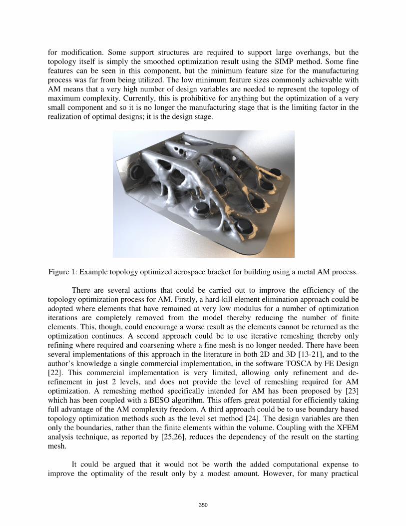
for modification. Some support structures are required to support large overhangs, but the
topology itself is simply the smoothed optimization result using the SIMP method. Some fine
features can be seen in this component, but the minimum feature size for the manufacturing
process was far from being utilized. The low minimum feature sizes commonly achievable with
AM means that a very high number of design variables are needed to represent the topology of
maximum complexity. Currently, this is prohibitive for anything but the optimization of a very
small component and so it is no longer the manufacturing stage that is the limiting factor in the
realization of optimal designs; it is the design stage.
Figure 1: Example topology optimized aerospace bracket for building using a metal AM process.
There are several actions that could be carried out to improve the efficiency of the
topology optimization process for AM. Firstly, a hard-kill element elimination approach could be
adopted where elements that have remained at very low modulus for a number of optimization
iterations are completely removed from the model thereby reducing the number of finite
elements. This, though, could encourage a worse result as the elements cannot be returned as the
optimization continues. A second approach could be to use iterative remeshing thereby only
refining where required and coarsening where a fine mesh is no longer needed. There have been
several implementations of this approach in the literature in both 2D and 3D [13-21], and to the
author’s knowledge a single commercial implementation, in the software TOSCA by FE Design
[22]. This commercial implementation is very limited, allowing only refinement and de-
refinement in just 2 levels, and does not provide the level of remeshing required for AM
optimization. A remeshing method specifically intended for AM has been proposed by [23]
which has been coupled with a BESO algorithm. This offers great potential for efficiently taking
full advantage of the AM complexity freedom. A third approach could be to use boundary based
topology optimization methods such as the level set method [24]. The design variables are then
only the boundaries, rather than the finite elements within the volume. Coupling with the XFEM
analysis technique, as reported by [25,26], reduces the dependency of the result on the starting
mesh.
It could be argued that it would not be worth the added computational expense to
improve the optimality of the result only by a modest amount. However, for many practical
350
applications, especially for aerospace, the use phase of the component is by far the most costly in
terms of fuel requirement, and even modest weight savings result in a huge overall cost saving
over the vehicles’ lifespan. This can justify the added computation time at the design stage.
Manufacturing Constraints
While the manufacturing constraints for AM are much less significant than traditional
manufacturing routes there are still some that require consideration. Many of the AM constraints
could be better termed manufacturing considerations, as they do not necessarily constrain the
design. The need for scaffold structures to support large overhangs is dependent on the specific
AM process used, as some do not require support structures at all. Up to a point, the processes
that require supports, can self-support so long as the overhang is above a particular angle to the
horizontal. With some of the metal processes, such as SLM, structures are required primarily to
restrict curling/warping of the melted powder due to high temperature gradients, rather than to
provide mechanical support. The need for support structures is also dependent on the geometry
and often consideration is given to modifying the design to make it self-supporting. The main
advantage of this is to reduce the post processing requirement of removing the support structures
from the designed component, which is commonly a manual task, but a potential reduction in
material usage is also a benefit. Some processes, such as fused deposition modeling (FDM) [27],
have water soluble supports which significantly reducing the post processing burden. Other
manufacturing constraints are build accuracy, surface finish and z-direction mechanical
properties, but these have less relevance to the topology of the component and so will not be
discussed here.
As mentioned in the previous section, depending on the specific component application,
weight savings can be the primary objective rather than a reduction in manufacturing costs, due
to energy use during the component use phase. In these cases, it would not be sensible to
increase the weight of the component to reduce manufacturing costs, by reducing the amount of
support structure. For applications where the manufacturing costs are more significant, then this
could be useful.
As yet, to the authors’ knowledge, there has been no research on methods for
incorporating specific AM manufacturing constraints into the topology optimization process. The
only existing applicable method is the minimum member thickness constraint [28-30] which is
applicable to the minimum feature size constraint for the AM processes. This constraint is
commonly found in commercial software such as Optistruct by Altair [31] and Nastran by MSC
[32]. A maximum overhang constraint would need to be based on the maximum horizontal
overhang distance and the angle of the overhang. A maximum thickness constraint as devised by
[33,34] and an instance of which has recently been added to Optistruct intended for casting
purposes, has some relevance to this issue. By limiting the maximum thickness of the members,
it would be expected that this would result in an increase in the quantity of members. This then
should reduce the horizontal overhang distance between members, thereby reducing the amount
of support structure required. However, it would be difficult to know what specific maximum
member thickness value to use in advance and it would likely require several runs to adjust this
parameter. It is also unlikely that this would completely eliminate the need for any support
material as it does not penalize large unsupported cavities edges.
351
Recent work by [35,36] has investigated the effect of varying the optimization parameters
of a BESO algorithm, specifically the checkerboard filter radius and the evolution rate. This was
with the intention of finding the parameters most suitable for AM to increase the complexity of
the design and reduce the need for support structures. It was found that the checkerboard filter
radius had some effect on the topology complexity, although it did not appear to have enough of
an effect to make a significant difference to the requirement for support structures.
For areas of the component that will mate with other components, or that require very
high accuracy, post machining may be necessary. Therefore, in these cases a machining
constraint would be useful to ensure the tooling can attain access to the relevant features of the
component.
First steps towards inclusion of AM specific manufacturing constraints into the topology
optimization process are being carried out by the authors. Specifically, this is for the support
structure requirement for certain processes, e.g. SLM. There are four main reasons why
minimizing the amount of support material required is useful.
1. Support structures require additional material to be used that is usually wasted as it cannot be
easily reused by the machine without regrinding it back to a powder.
2. The set up of STL models ready for building requires specification of the build orientation
and the subsequent generation and placement of support structures. This commonly requires
manual intervention based on the expertise of the technicians.
3. The removal of support structures after building usually requires a significant amount of
manual work, especially in the case of metal processes.
4. The requirement for manual removal from the part constrains the geometric freedom of the
part as there needs to be hand/tool access.
To include the requirement for the geometry to self support would reduce the need for these
aforementioned requirements. The horizontal overhang distance that can self support is
dependent on the angle of the edge/face, e.g. hypothetically, for a 30° angle it may be able to self
support up to 20mm, but for a 25° angle only up to 15mm. After approximately 45° from the
horizontal, the distance that it could self support is not limited. So there are some combinations
of angle and horizontal distance that are allowed, but other combinations that are not preferred.
Being able to steer the optimization as it progresses to avoid these violations and move towards
viable combinations is the objective of this manufacturing constraint.
The BESO algorithm was used for this work because its inherent solid-void
representation means that it is easier to identify boundaries than with variable density methods.
The implementation of this approach is now explained with an example topology optimization
result. At each iteration of the BESO algorithm, an assessment is made of the downward facing
edge angles and their horizontal overhang distance. This is done using the following method:
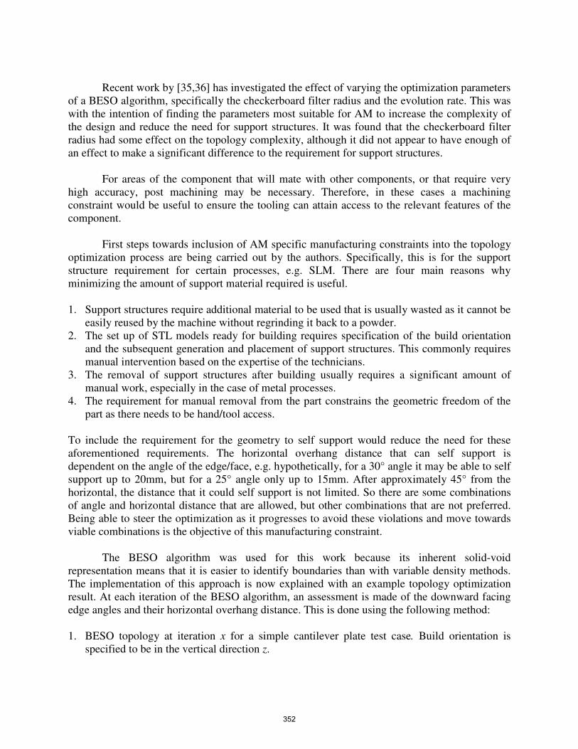
1. BESO topology at iteration x for a simple cantilever plate test case. Build orientation is
specified to be in the vertical direction z.
352
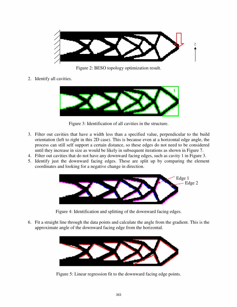
Figure 2: BESO topology optimization result.
2. Identify all cavities.
Figure 3: Identification of all cavities in the structure.
3. Filter out cavities that have a width less than a specified value, perpendicular to the build
orientation (left to right in this 2D case). This is because even at a horizontal edge angle, the
process can still self support a certain distance, so these edges do not need to be considered
until they increase in size as would be likely in subsequent iterations as shown in Figure 7.
4. Filter out cavities that do not have any downward facing edges, such as cavity 1 in Figure 3.
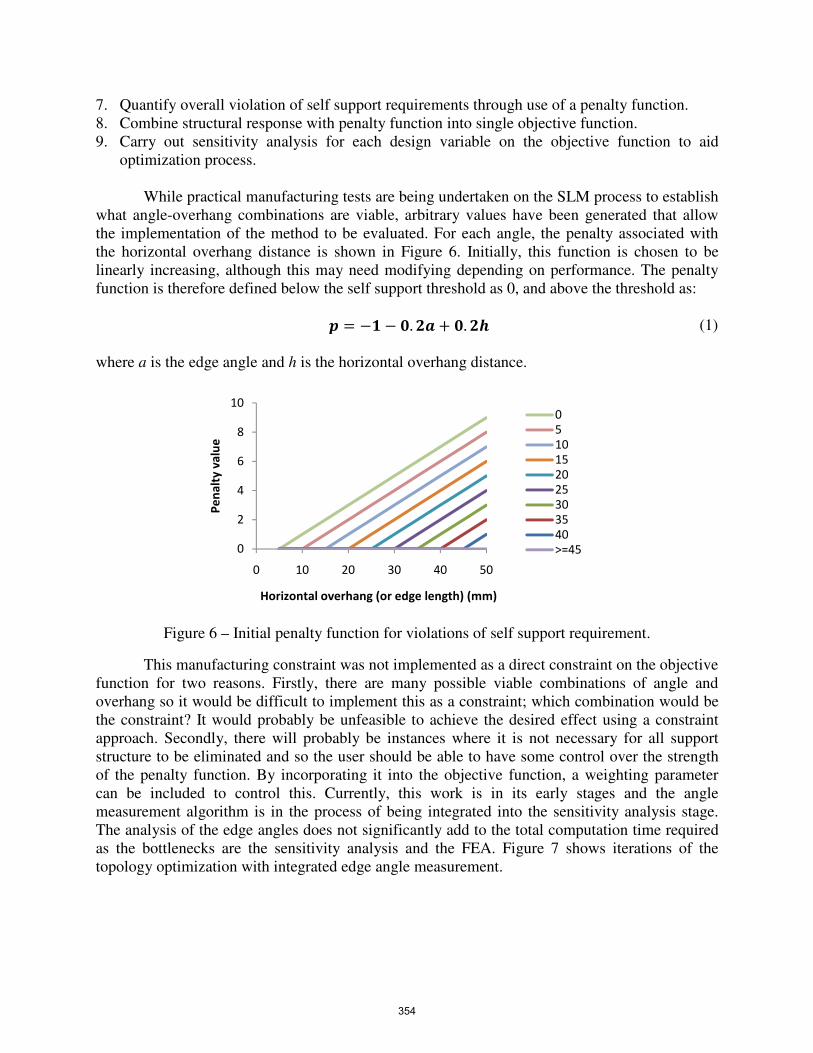
5. Identify just the downward facing edges. These are split up by comparing the element
coordinates and looking for a negative change in direction.
Figure 4: Identification and splitting of the downward facing edges.
6. Fit a straight line through the data points and calculate the angle from the gradient. This is the
approximate angle of the downward facing edge from the horizontal.
Figure 5: Linear regression fit to the downward facing edge points.
1
z
Edge 1 Edge 2
353
7. Quantify overall violation of self support requirements through use of a penalty function.
8. Combine structural response with penalty function into single objective function.
9. Carry out sensitivity analysis for each design variable on the objective function to aid
optimization process.
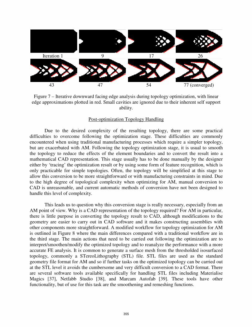
While practical manufacturing tests are being undertaken on the SLM process to establish
what angle-overhang combinations are viable, arbitrary values have been generated that allow
the implementation of the method to be evaluated. For each angle, the penalty associated with
the horizontal overhang distance is shown in Figure 6. Initially, this function is chosen to be
linearly increasing, although this may need modifying depending on performance. The penalty
function is therefore defined below the self support threshold as 0, and above the threshold as:
� � �� � �. �� �. � (1)
where a is the edge angle and h is the horizontal overhang distance.
Figure 6 – Initial penalty function for violations of self support requirement.
This manufacturing constraint was not implemented as a direct constraint on the objective
function for two reasons. Firstly, there are many possible viable combinations of angle and
overhang so it would be difficult to implement this as a constraint; which combination would be
the constraint? It would probably be unfeasible to achieve the desired effect using a constraint
approach. Secondly, there will probably be instances where it is not necessary for all support
structure to be eliminated and so the user should be able to have some control over the strength
of the penalty function. By incorporating it into the objective function, a weighting parameter
can be included to control this. Currently, this work is in its early stages and the angle
measurement algorithm is in the process of being integrated into the sensitivity analysis stage.
The analysis of the edge angles does not significantly add to the total computation time required
as the bottlenecks are the sensitivity analysis and the FEA. Figure 7 shows iterations of the
topology optimization with integrated edge angle measurement.
0
2
4
6
8
10
0 10 20 30 40 50
Pe
na
lty
va
lue
Horizontal overhang (or edge length) (mm)
0
5
10
15
20
25
30
35
40
>=45
354
Iteration 1 9 17 26
43 47 54 77 (converged)
Figure 7 – Iterative downward facing edge analysis during topology optimization, with linear
edge approximations plotted in red. Small cavities are ignored due to their inherent self support
ability.
Post-optimization Topology Handling
Due to the desired complexity of the resulting topology, there are some practical
difficulties to overcome following the optimization stage. These difficulties are commonly
encountered when using traditional manufacturing processes which require a simpler topology,
but are exacerbated with AM. Following the topology optimization stage, it is usual to smooth
the topology to reduce the effects of the element boundaries and to convert the result into a
mathematical CAD representation. This stage usually has to be done manually by the designer
either by ‘tracing’ the optimization result or by using some form of feature recognition, which is
only practicable for simple topologies. Often, the topology will be simplified at this stage to
allow this conversion to be more straightforward or with manufacturing constraints in mind. Due
to the high degree of topological complexity when optimizing for AM, manual conversion to
CAD is unreasonable, and current automatic methods of conversion have not been designed to
handle this level of complexity.
This leads us to question why this conversion stage is really necessary, especially from an
AM point of view. Why is a CAD representation of the topology required? For AM in particular,
there is little purpose in converting the topology result to CAD, although modifications to the
geometry are easier to carry out in CAD software and it makes constructing assemblies with
other components more straightforward. A modified workflow for topology optimization for AM
is outlined in Figure 8 where the main differences compared with a traditional workflow are in
the third stage. The main actions that need to be carried out following the optimization are to
interpret/smoothen/modify the optimized topology and to reanalyze the performance with a more
accurate FE analysis. It is common to generate a surface mesh from the thresholded isosurfaced
topology, commonly a STereoLithography (STL) file. STL files are used as the standard
geometry file format for AM and so if further tasks on the optimized topology can be carried out
at the STL level it avoids the cumbersome and very difficult conversion to a CAD format. There
are several software tools available specifically for handling STL files including Materialise
Magics [37], Netfabb Studio [38], and Marcam Autofab [39]. These tools have other
functionality, but of use for this task are the smoothening and remeshing functions.
355
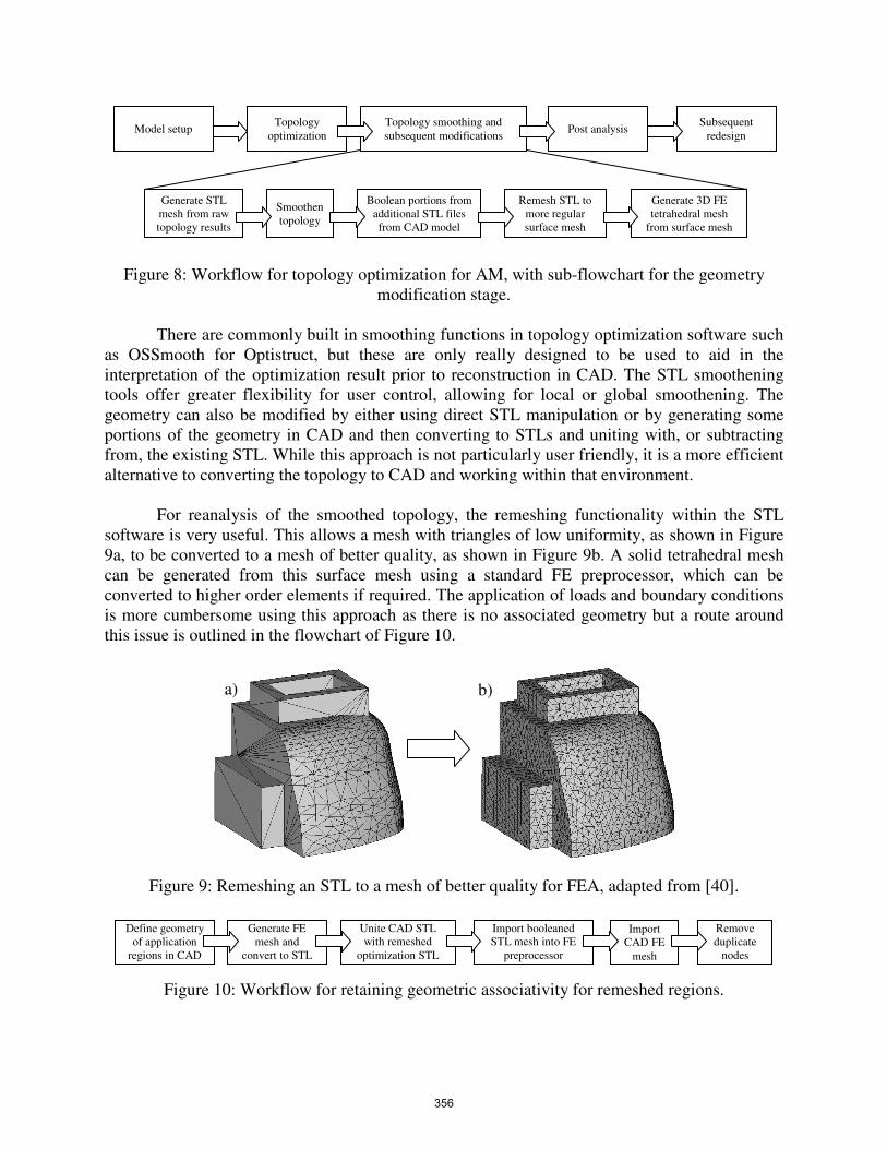
Figure 8: Workflow for topology optimization for AM, with sub-flowchart for the geometry
modification stage.
There are commonly built in smoothing functions in topology optimization software such
as OSSmooth for Optistruct, but these are only really designed to be used to aid in the
interpretation of the optimization result prior to reconstruction in CAD. The STL smoothening
tools offer greater flexibility for user control, allowing for local or global smoothening. The
geometry can also be modified by either using direct STL manipulation or by generating some
portions of the geometry in CAD and then converting to STLs and uniting with, or subtracting
from, the existing STL. While this approach is not particularly user friendly, it is a more efficient
alternative to converting the topology to CAD and working within that environment.
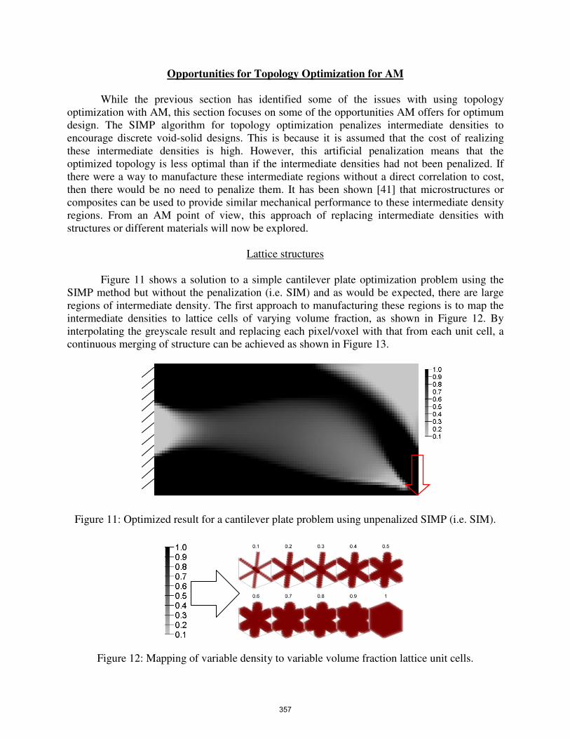
For reanalysis of the smoothed topology, the remeshing functionality within the STL
software is very useful. This allows a mesh with triangles of low uniformity, as shown in Figure
9a, to be converted to a mesh of better quality, as shown in Figure 9b. A solid tetrahedral mesh
can be generated from this surface mesh using a standard FE preprocessor, which can be
converted to higher order elements if required. The application of loads and boundary conditions
is more cumbersome using this approach as there is no associated geometry but a route around
this issue is outlined in the flowchart of Figure 10.
Figure 9: Remeshing an STL to a mesh of better quality for FEA, adapted from [40].
Figure 10: Workflow for retaining geometric associativity for remeshed regions.
Import
CAD FE
mesh
Import booleaned
STL mesh into FE
preprocessor
Unite CAD STL
with remeshed
optimization STL
Generate FE
mesh and
convert to STL
Define geometry
of application
regions in CAD
Remove
duplicate
nodes
Model setup Topology
optimization
Topology smoothing and
subsequent modifications Post analysis
Subsequent
redesign
Generate STL
mesh from raw
topology results
Smoothen
topology
Boolean portions from
additional STL files
from CAD model
Remesh STL to
more regular
surface mesh
Generate 3D FE
tetrahedral mesh
from surface mesh
a) b)
356
Opportunities for Topology Optimization for AM
While the previous section has identified some of the issues with using topology
optimization with AM, this section focuses on some of the opportunities AM offers for optimum
design. The SIMP algorithm for topology optimization penalizes intermediate densities to
encourage discrete void-solid designs. This is because it is assumed that the cost of realizing
these intermediate densities is high. However, this artificial penalization means that the
optimized topology is less optimal than if the intermediate densities had not been penalized. If
there were a way to manufacture these intermediate regions without a direct correlation to cost,
then there would be no need to penalize them. It has been shown [41] that microstructures or
composites can be used to provide similar mechanical performance to these intermediate density
regions. From an AM point of view, this approach of replacing intermediate densities with
structures or different materials will now be explored.
Lattice structures
Figure 11 shows a solution to a simple cantilever plate optimization problem using the
SIMP method but without the penalization (i.e. SIM) and as would be expected, there are large
regions of intermediate density. The first approach to manufacturing these regions is to map the
intermediate densities to lattice cells of varying volume fraction, as shown in Figure 12. By
interpolating the greyscale result and replacing each pixel/voxel with that from each unit cell, a
continuous merging of structure can be achieved as shown in Figure 13.
Figure 11: Optimized result for a cantilever plate problem using unpenalized SIMP (i.e. SIM).
Figure 12: Mapping of variable density to variable volume fraction lattice unit cells.
357
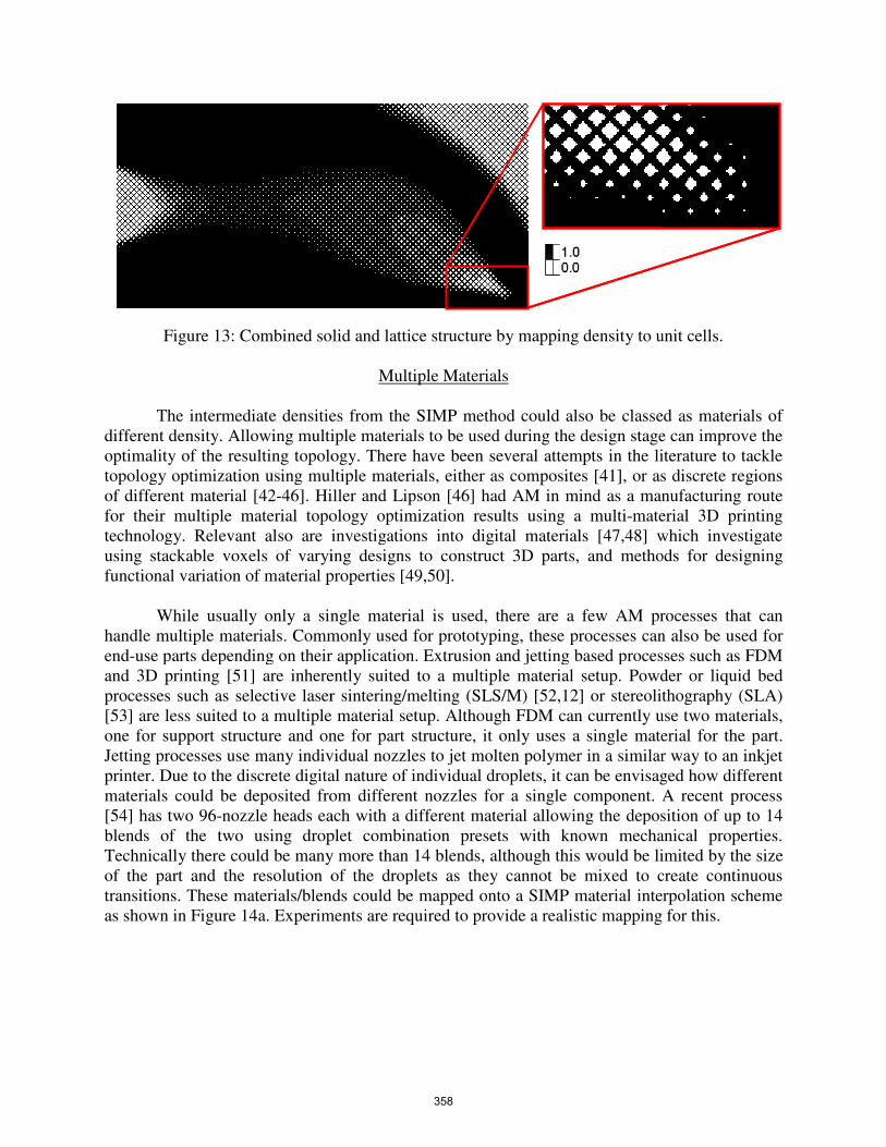
Figure 13: Combined solid and lattice structure by mapping density to unit cells.
The intermediate densities from the SIMP method could also be classed as materials of
different density. Allowing multiple materials to be used during the design stage can improve the
optimality of the resulting topology. There have been several attempts in the literature
topology optimization using multiple mat
of different material [42-46]. Hiller and Lipson [46
for their multiple material topology optimization resu
technology. Relevant also are investiga
using stackable voxels of varying designs to construct 3D parts, and methods for designing
functional variation of material properties [49,50
While usually only a single material is used, there are a few AM processes that can
handle multiple materials. Commonly used for prototyping, these processes can also be used for
end-use parts depending on their application. Extrusion
and 3D printing [51] are inherently suited to a multiple material setup. Powder or liquid bed
processes such as selective laser sintering/melting (SLS/M) [52,12] or stereolithography (SLA)
[53] are less suited to a multiple material setup. Although FDM can currently use two materials,
one for support structure and one for part structure, it only uses a single material for the part.
Jetting processes use many individual nozzles to jet molten polymer in a similar way t
printer. Due to the discrete digital nature of individual droplets, it can be envisaged how different
materials could be deposited from different nozzles for a single
[54] has two 96-nozzle heads each with a differen
blends of the two using droplet combination presets wi
Technically there could be many more than 14 blends, although this would be limited by the size
of the part and the resolution of the droplets as they cannot be mixed to create continuous
transitions. These materials/blends could be mapped onto a SIMP material interpola
as shown in Figure 14a. Experiments are required to provide a realistic mapping for this.
: Combined solid and lattice structure by mapping density to unit cells.
Multiple Materials
densities from the SIMP method could also be classed as materials of
different density. Allowing multiple materials to be used during the design stage can improve the
optimality of the resulting topology. There have been several attempts in the literature
topology optimization using multiple materials, either as composites [41], or as discrete r
46]. Hiller and Lipson [46] had AM in mind as a manufacturing route
for their multiple material topology optimization results using a multi-material 3D printing
technology. Relevant also are investigations into digital materials [47,48] which investigate
using stackable voxels of varying designs to construct 3D parts, and methods for designing
properties [49,50].
While usually only a single material is used, there are a few AM processes that can
handle multiple materials. Commonly used for prototyping, these processes can also be used for
use parts depending on their application. Extrusion and jetting based processes
] are inherently suited to a multiple material setup. Powder or liquid bed
er sintering/melting (SLS/M) [52,12] or stereolithography (SLA)
multiple material setup. Although FDM can currently use two materials,
one for support structure and one for part structure, it only uses a single material for the part.
Jetting processes use many individual nozzles to jet molten polymer in a similar way t
printer. Due to the discrete digital nature of individual droplets, it can be envisaged how different
materials could be deposited from different nozzles for a single component. A recent process
nozzle heads each with a different material allowing the deposition of up to 14
blends of the two using droplet combination presets with known mechanical properties.
Technically there could be many more than 14 blends, although this would be limited by the size
ion of the droplets as they cannot be mixed to create continuous
transitions. These materials/blends could be mapped onto a SIMP material interpola
. Experiments are required to provide a realistic mapping for this.
: Combined solid and lattice structure by mapping density to unit cells.
densities from the SIMP method could also be classed as materials of
different density. Allowing multiple materials to be used during the design stage can improve the
optimality of the resulting topology. There have been several attempts in the literature to tackle
], or as discrete regions
] had AM in mind as a manufacturing route
material 3D printing
] which investigate
using stackable voxels of varying designs to construct 3D parts, and methods for designing
While usually only a single material is used, there are a few AM processes that can
handle multiple materials. Commonly used for prototyping, these processes can also be used for
and jetting based processes such as FDM
] are inherently suited to a multiple material setup. Powder or liquid bed
er sintering/melting (SLS/M) [52,12] or stereolithography (SLA)
multiple material setup. Although FDM can currently use two materials,
one for support structure and one for part structure, it only uses a single material for the part.
Jetting processes use many individual nozzles to jet molten polymer in a similar way to an inkjet
printer. Due to the discrete digital nature of individual droplets, it can be envisaged how different
component. A recent process
t material allowing the deposition of up to 14
th known mechanical properties.
Technically there could be many more than 14 blends, although this would be limited by the size
ion of the droplets as they cannot be mixed to create continuous
transitions. These materials/blends could be mapped onto a SIMP material interpolation scheme
. Experiments are required to provide a realistic mapping for this.
358
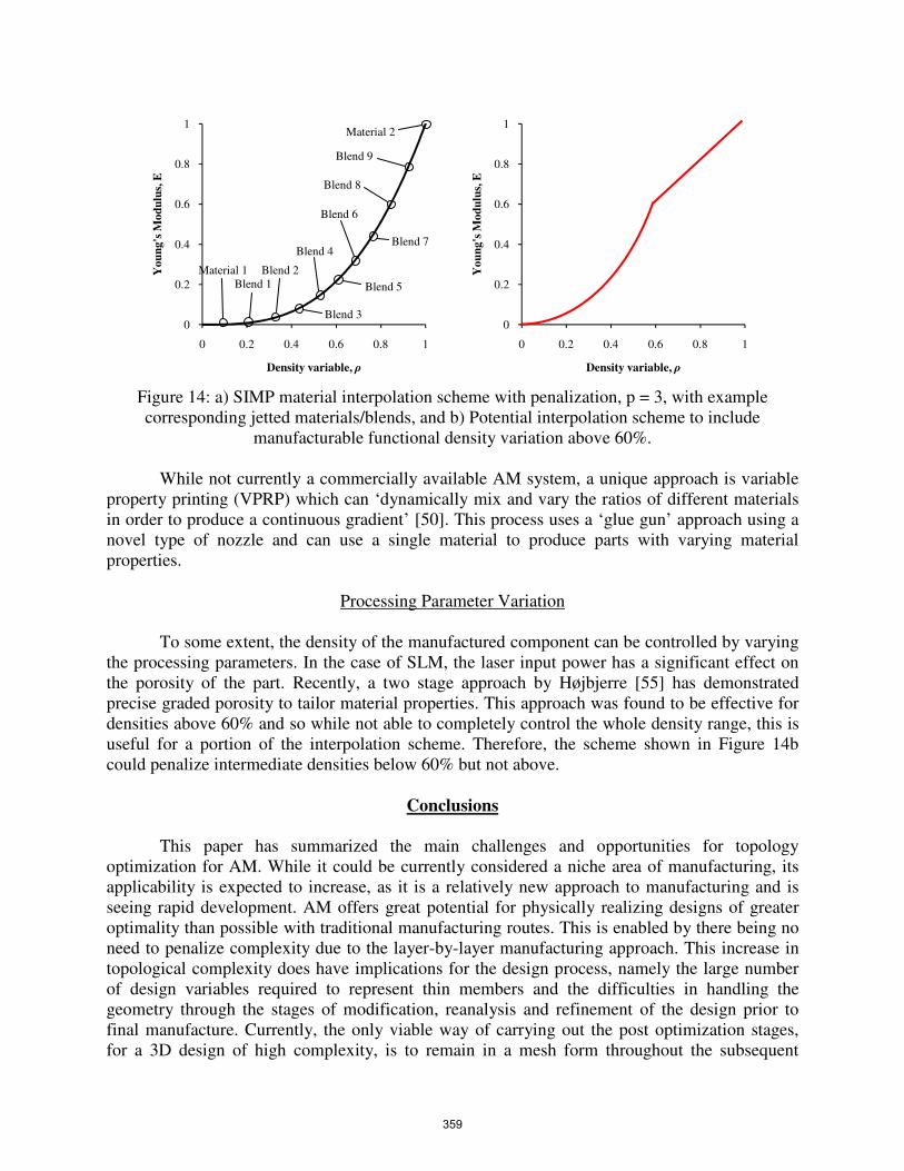
Figure 14: a) SIMP material interpolation scheme with penalization, p = 3, with example
corresponding jetted materials/blends, and b) Potential interpolation scheme to include
manufacturable functional density variation above 60%.
While not currently a commercially available AM system, a unique approach is variable
property printing (VPRP) which can ‘dynamically mix and vary the ratios of different materials
in order to produce a continuous gradient’ [50]. This process uses a ‘glue gun’ approach using a
novel type of nozzle and can use a single material to produce parts with varying material
properties.
Processing Parameter Variation
To some extent, the density of the manufactured component can be controlled by varying
the processing parameters. In the case of SLM, the laser input power has a significant effect on
the porosity of the part. Recently, a two stage approach by Højbjerre [55] has demonstrated
precise graded porosity to tailor material properties. This approach was found to be effective for
densities above 60% and so while not able to completely control the whole density range, this is
useful for a portion of the interpolation scheme. Therefore, the scheme shown in Figure 14b
could penalize intermediate densities below 60% but not above.
Conclusions
This paper has summarized the main challenges and opportunities for topology
optimization for AM. While it could be currently considered a niche area of manufacturing, its
applicability is expected to increase, as it is a relatively new approach to manufacturing and is
seeing rapid development. AM offers great potential for physically realizing designs of greater
optimality than possible with traditional manufacturing routes. This is enabled by there being no
need to penalize complexity due to the layer-by-layer manufacturing approach. This increase in
topological complexity does have implications for the design process, namely the large number
of design variables required to represent thin members and the difficulties in handling the
geometry through the stages of modification, reanalysis and refinement of the design prior to
final manufacture. Currently, the only viable way of carrying out the post optimization stages,
for a 3D design of high complexity, is to remain in a mesh form throughout the subsequent
0
0.2
0.4
0.6
0.8
1
0 0.2 0.4 0.6 0.8 1
Yo
un
g's
Mo
du
lus,
E
Density variable, ρ
0
0.2
0.4
0.6
0.8
1
0 0.2 0.4 0.6 0.8 1
Yo
un
g's
Mo
du
lus,
E
Density variable, ρ
Material 1
Material 2
Blend 1
Blend 2
Blend 3
Blend 4
Blend 5
Blend 6
Blend 7
Blend 8
Blend 9
359
stages instead of converting to a CAD model. This can be achieved using STL manipulation
tools combined with some use of CAD software to assist with certain tasks. The requirement for
several AM processes to use support structures for large overhangs provides justification for
investigating methods for including this measure into the optimization process to reduce material
usage and subsequent post processing.
As well as being able to manufacture components with greater geometric complexity,
other opportunities for AM were discussed. These focused on possibilities to realize regions of
intermediate density using either small scale lattice structures or by using multiple material
processes. Work is needed to investigate this further and correlate the performance of both
representations with the variable density isotropic performance.
AM provides a route to physically realize very complex topologies that are of greater
optimality than achievable with traditional manufacturing processes. Improvements to the
efficiency of the topology optimization methods to allow small and large scale features to coexist
without requiring a prohibitive number of design variables are required. The level set approach
appears to offer some potential on this issue where the design variables are the boundaries rather
than the volume. Tools to aid the designer in handling geometric complexity are also required. It
is perhaps unrealistic to expect a panacea of automatic tools to feature recognize and convert
complex topology meshes into a mathematical CAD form, but this would be very useful. Until
there are further developments in this area, remaining in the mesh form for geometric post-
processing appears to be the only realistic way of retaining the level of complexity in the design.
Acknowledgements
The authors would like to thank the UK Technology Strategy Board (TSB) [43] for
funding this work and the Atkins project partners.
References
[1] Bendsoe M. P., and Kikuchi, N., Generating optimal topologies in structural design using a homogenization
method, Computer Methods in Applied Mechanics and Engineering, 71, 1988
[2] Bendsoe M. P., and Sigmund, O., Topological Optimization, Theory, Methods and Application, Springer-
Verlag, Berlin, 2004
[3] Rozvany, G. I. N., Zhou, M., and Birker, T., Generalized shape optimization without homogenization,
Structural Optimization, 4, 250-252, 1992
[4] Rozvany, G. I. N., A critical review of established methods of structural topology optimization, Structural
and Multidisciplinary Optimization, 37, 217-237, 2001
[5] Querin, O. M., Steven, G. P., and Xie, Y. M., Evolutionary structural optimization using a bi-directional
algorithm, Engineering Computations, 15 (8), 1031-1048, 1998
[6] Querin, O. M., Steven, G. P., and Xie, Y. M., Evolutionary structural optimization using an additive
algorithm, Finite Element in Analysis and Design, 34, 291-308, 2000
[7] Querin, O. M., Young, V., Steven, G. P., and Xie, Y. M., Computational efficiency and validation of bi-
directional evolutionary structural optimization, Computer Methods in Applied Mechanical Engineering,
189, 559-573, 2000
[8] Huang, X., and Xie, Y. M., Convergent and mesh-independent solutions for the bi-directional evolutionary
structural optimization method, Finite Elements in Analysis and Design, 43, 1039-1040, 2007
[9] Huang, X., and Xie, Y. M., Evolutionary topology optimization of continuum structures: Methods and
Applications, John Wiley and Sons, West Sussex, 2010
[10] atkins-project.com. Project: Atkins – Rapid Manufacturing a Low Carbon Footprint, funded by Technology
360
Strategy Board (TSB). Accessed 06-05-11.
[11] Sigmund, O., On the usefulness of non-gradient approaches in topology optimization, Structural and
Multidisciplinary Optimization, 43, 589-596, 2011.
[12] www.mtt-group.com/selective-laser-melting.html. MTT Direct Metals Manufacturing Technology,
Accessed 06-05-11.
[13] de Sturler, E., Paulion, G. H., and Wang, S., Topology optimization with adaptive mesh refinement,
Proceedings of the 6th
International Conference on Computation of Shell and Spatial Structures IASS-
IACM, “Spanning Nano to Mega”, Cornell University, Ithaca, NY, USA, 2008.
[14] James, K. A., Hansen, J. S., Martins, J. R. R. A., Structural topology optimization for multiple load cases
using a dynamic aggregation technique, Engineering Optimization, 41 (12), 1103-1118, 2009.
[15] Liu, Z., and Korvink, J. G., Adaptive moving mesh level set method for structure topology optimization,
Engineering Optimization, 40 (6), 529-558, 2008.
[16] Maute, K., and Ramm, E., Adaptive topology optimization, Structural Optimization, 10 (2), 100-112, 1995.
[17] Nguyen, T. H., Paulino, G. H., Song, J., and Le, C. H., A computational paradigm for multiresolution
topology optimization (MTOP), Structural and Multidisciplinary Optimization, 41, 525-539, 2010.
[18] Verani, M., Bruggi, M., Cinquini, C., and Venini, P., Topology optimization and mesh adaptivity, XVIII
GIMC Conference, Siracusa, 2010.
[19] Wang, S., de Sturler, E., and Paulino, G. H., Dynamic adaptive mesh refinement for topology optimization,
International Journal of Numerical Methods, 69, 2441-2468, 2008.
[20] Wang, S., Krylov subspace methods for topology optimization on adaptive meshes, PhD Thesis, University
of Illinois at Urbana-Champaign, 2007.
[21] Stainko, R., An adaptive multilevel approach to the minimal compliance problem in topology optimization,
Communications in Numerical Methods in Engineering, 22, 109-118, 2006.
[22] www.fe-design.de/en/products/tosca-structure/topology/. FE Design TOSCA Structure.topology software.
Accessed 06-05-11.
[23] Aremu, A., Brackett, D., Ashcroft, I., Wildman, R., Hague, R., and Tuck, C., An adaptive meshing based
BESO topology optimisation, 9th
World Congress on Structural and Multidisciplinary Optimization,
Shizuoka, Japan, 2011 (in press).
[24] Wang, M. Y., Wang, X., and Guo, D., A level set method for structural topology optimization, Computer
Methods in Applied Mechanics and Engineering, 192 (1-2), 227-246, 2003.
[25] Wei, P., and Wang, M. Y., A structural optimization method with XFEM and level set model, Proceedings
of the TMCE, Izmir, Turkey, 2008.
[26] Wei, P, and Wang, M. Y., Continuum structural optimization with level set model and X-FEM, 8th
World
Congress on Structural and Multidisciplinary Optimization (WCSMO-8), Lisbon, Portugal, 2009.
[27] www.stratasys.com/Solutions/Technology.aspx. Stratasys FDM system. Accessed 06-05-11.
[28] Petersson, J., and Sigmund, O., Numerical Instabilities in topology optimization: a survey of procedures
dealing with checkerboards, mesh-dependencies and local minima, Structural Optimization, 16, 1998, 68-75
[29] Poulsen, T. A., A new scheme for imposing minimum length scale in topology optimization, International
Journal for Numerical Methods in Engineering, 57, 2003, 741-760
[30] Guest, J. K., Prevost, J. H., and Belytschko, T., Achieving minimum length scale in topology optimization
using nodal design variables and projection functions, International Journal for Numerical Methods in
Engineering, 61, 2004, 238-254
[31] www.altairhyperworks.com/Product,19,OptiStruct.aspx. Altair Optistruct software. Accessed 06-05-11.
[32] MSC Nastran FE Solver by MSC.Software Corporation, 2 MacArthur Place, Santa Ana, California,
http://www.mscsoftware.com, Accessed 11-07-11.
[33] Guest, J. K., and Prevost, J. H., A penalty function for enforcing maximum length scale criterion in
topology optimization, Proceedings of the 11th
AIAA/ISSMO Multidisciplinary Analysis and Optimization
Conference, 6-8 September 2006, Portsmouth, Virginia
[34] Guest, J. K., Imposing maximum length scale in topology optimization, Structural and Multidisciplinary
Optimization, 37, 2009, 463-473
[35] Aremu, A., Ashcroft, I., Hague, R., Wildman, R., and Tuck, C., Suitability of SIMP and BESO topology
optimization algorithms for additive manufacture, 21st Annual International Solid Freeform Fabrication
Symposium (SFF) – An Additive Manufacturing Conference, Austin, Texas, 679-692, 2010.
[36] Aremu, A., Ashcroft, I., Hague, R., Wildman, R., Tuck, C., Brackett, D., A parametric analysis of BESO
topology optimization algorithm, Structural and Multidisciplinary Optimization, (Submitted), 2011.
361
[37] www.materialise.com/Magics. Materialise Magics software. Accessed 06-05-11.
[38] www.netfabb.com. Netfabb software. Accessed 06-05-11.
[39] www.marcam.de/cms/autofab.82.en.html. Marcam Engineering Autofab software. Accessed 06-05-11.
[40] Brennan-Craddock, J.P.J., The development of a method to generate conformal structures for additive
manufacturing, PhD Thesis, Loughborough University, 2011 (in press).
[41] Bendsoe, M. P., and Sigmund, O., Material interpolation schemes in topology optimization, Archive of
Applied Mechanics, 69 (9-10), 635-654, 1999.
[42] Sigmund, O., and Torquato, S., Design of materials with extreme thermal expansion using a three-phase
topology optimization method, Journal of the Mechanics and Physics of Solids, 45 (6), 1037-1067, 1997.
[43] Yin, L., and Ananthasuresh, G. K., Topology optimization of compliant mechanisms with multiple
materials using a peak function material interpolation scheme, Structural and Multidisciplinary
Optimization, 23, 49-62, 2001.
[44] Wang, M. Y., and Wang, X., “Color” level sets: a multi-phase method for structural topology optimization
with multiple materials, Computational Methods of Applied Mechanical Engineering, 193, 469-496, 2004.
[45] Huang, X., and Xie, Y. M., Bi-directional evolutionary topology optimization of continuum structures with
one or multiple materials, Computational Mechanics, 43, 393-401, 2009.
[46] Hiller, J. D., and Lipson, H., Multi material topological optimization of structures and mechanisms,
Proceedings of the 11th
Annual Conference on Genetic and Evolutionary Computation (GECCO ’09), 1521-
1528, 2009.
[47] Hiller, J. D., and Lipson, H., Design and analysis of digital materials for physical 3D voxel printing, Rapid
Prototyping Journal, 15 (2), 137-149, 2009.
[48] Hiller, J. D., and Lipson, H., Tunable digital material properties for 3D voxel printers, Rapid Prototyping
Journal, 16 (4), 241-247, 2010.
[49] Knoppers, G. E., Dijkstra, J., and van Vliet, W. P., The design of graded material objects, TNO Science and
Industry, The Netherlands, 2006.
[50] Oxman, N., Material-based design computation, PhD Thesis, Massachusetts Institute of Technology, 2010.
[51] www.zcorp.com/en/Products/3D-Printers/spage.aspx. ZCorporation 3D printers. Accessed 06-05-11.
[52] www.3dsystems.com/products/sls/index.asp. 3D Systems SLS process. Accessed 06-05-11.
[53] www.3dsystems.com/products/sla/index.asp. 3D Systems SLA processed. Accessed 06-05-11.
[54] www.objet.com/PRODUCTS/PolyJet_Matrix_Technology/. Objet Polyjet Matrix technology. Accessed 06-
05-11.
[55] Højbjerre, K., Additive manufacturing of porous metal components, Proceedings of the 6th
International
Conference on Additive Manufacturing, Loughborough, July 2011
362