topological drawings of complete bipartite...
TRANSCRIPT
Topological Drawings of Complete Bipartite
Graphs
Jean Cardinal � Stefan Felsner y
July 2018
Abstract
Topological drawings are natural representations of graphs in the plane, where
vertices are represented by points, and edges by curves connecting the points.
Topological drawings of complete graphs and of complete bipartite graphs have
been studied extensively in the context of crossing number problems. We consider
a natural class of simple topological drawings of complete bipartite graphs, in which
we require that one side of the vertex set bipartition lies on the outer boundary of
the drawing.
We investigate the combinatorics of such drawings. For this purpose, we de�ne
combinatorial encodings of the drawings by enumerating the distinct drawings of
subgraphs isomorphic to K2,2 and K3,2, and investigate the constraints they must
satisfy. We prove that a drawing of Kk,n exists if and only if some simple local
conditions are satis�ed by the encodings. This directly yields a polynomial-time
algorithm for deciding the existence of such a drawing given the encoding. We show
the encoding is equivalent to specifying which pairs of edges cross, yielding a similar
polynomial-time algorithm for the realizability of abstract topological graphs.
We also completely characterize and enumerate such drawings of Kk,n in which
the order of the edges around each vertex is the same for vertices on the same
side of the bipartition. Finally, we investigate drawings of Kk,n using straight lines
and pseudolines, and consider the complexity of the corresponding realizability
problems.
Contents
1 Introduction 2
2 Outer Drawings with uniform rotation system 42.1 The triple rule . . . . . . . . . . . . . . . . . . . . . . . . . . . . . . . . 62.2 The quadruple rule . . . . . . . . . . . . . . . . . . . . . . . . . . . . . . 72.3 Decomposability and Counting . . . . . . . . . . . . . . . . . . . . . . . 7
�Universit�e libre de Bruxelles (ULB), Brussels, Belgium. [email protected] Universit�at Berlin, Germany. [email protected].
1
3 Outer Drawings with k = 2 93.1 Triples . . . . . . . . . . . . . . . . . . . . . . . . . . . . . . . . . . . . . 103.2 Quadruples . . . . . . . . . . . . . . . . . . . . . . . . . . . . . . . . . . 113.3 Consistency . . . . . . . . . . . . . . . . . . . . . . . . . . . . . . . . . . 12
4 Outer Drawings with k = 3 144.1 The consistency theorem for k = 3 . . . . . . . . . . . . . . . . . . . . . 154.2 Outline of the Proof of Proposition 19 . . . . . . . . . . . . . . . . . . . 194.3 Case analysis for the proof of Proposition 19 . . . . . . . . . . . . . . . 21
4.3.1 The eight basic con�gurations . . . . . . . . . . . . . . . . . . . . 214.3.2 Proof of Lemma 21 . . . . . . . . . . . . . . . . . . . . . . . . . . 24
5 Outer Drawings with arbitrary k 27
6 Extendable and Straight-line Outer Drawings 296.1 Extendable Outer Drawings . . . . . . . . . . . . . . . . . . . . . . . . . 296.2 Straight-line Outer Drawings . . . . . . . . . . . . . . . . . . . . . . . . 30
7 Open problems 32
1 Introduction
We consider topological graph drawings, which are drawings of simple undirectedgraphs where vertices are represented by points in the plane, and edges are representedby simple curves that connect the corresponding points. We typically restrict thosedrawings to satisfy some natural nondegeneracy conditions. In particular, we considersimple drawings, in which every pair of edges intersect at most once. A common vertexcounts as an intersection.
While being perhaps the most natural and the most used representations of graphs,simple drawings are far from being understood from the combinatorial point of view.A prominent illustration is the problem of identifying the minimum number of edgecrossings in a simple topological drawing of Kn [10, 3, 1] or of Kk,n [22, 4], for whichthere are long standing conjectures.
In order to cope with the inherent complexity of the drawings, it is useful to considercombinatorial abstractions. Those abstractions are discrete structures encoding somefeatures of a drawing. One such abstraction, introduced by Kratochv��l, Lubiw, andNe�set�ril, is called abstract topological graphs (AT-graph) [12]. An AT-graph consists
of a graph (V, E) together with a set X ��E2
�. A topological drawing is said to realize
an AT-graph if the pairs of edges that cross are exactly those inX. Another abstractionof a topological drawing is called the rotation system. The rotation system associatesa circular permutation with every vertex v, which in a realization must correspond tothe order in which the neighbors of v are connected to v. Natural realizability problemsare: given an AT-graph or a rotation system, is it realizable as a topological drawing?The realizability problem for AT-graphs is known to be NP-complete [13].
For simple topological drawings of complete graphs, the two abstractions are ac-tually equivalent [19]. It is possible to reconstruct the set of crossing pairs of edges
2

by looking at the rotation system, and vice-versa (up to reversal of all permutations).Kyn�cl recently proved the remarkable result that a complete AT-graph (an AT-graphfor which the underlying graph is complete) can be realized as a simple topologicaldrawing of Kn if and only if all the AT-subgraphs on at most 6 vertices are realiz-able [14, 16]. This directly yields a polynomial-time algorithm for the realizabilityproblem. While this provides a key insight on topological drawings of complete graphs,similar realizability problems already appear much more di�cult when they involvecomplete bipartite graphs. In that case, knowing the rotation system is not su�cientfor reconstructing the intersecting pairs of edges.
We propose a �ne-grained analysis of simple topological drawings of complete bi-partite graphs. In order to make the analysis more tractable, we introduce a naturalrestriction on the drawings, by requiring that one side of the vertex set bipartition lieson a circle at in�nity. This gives rise to meaningful, yet complex enough, combinatorialstructures.
Definitions. We wish to draw the complete bipartite graph Kk,n in the plane in such away that:
1. vertices are represented by points,
2. edges are continuous curves that connect those points, and do not contain anyother vertices than their two endpoints
3. no more than two edges intersect in one point,
4. edges pairwise intersect at most once; in particular, edges incident to the samevertex intersect only at this vertex,
5. the k vertices of one side of the bipartition lie on the outer boundary of thedrawing.
Properties 1{4 are the usual requirements for simple topological drawings, alsoknown as good drawings. As we will see, Property 5 leads to drawings with interestingcombinatorial structures. We will refer to drawings satisfying Properties 1{5 as outerdrawings. Since this is the only type of drawings we consider, we will use the singleterm drawing instead when the context is clear.
The set of vertices of a bipartite graph Kk,n will be denoted by P[V, where P and Vare the two sides of the bipartition, with |P| = k and |V | = n. When we consider a givendrawing, we will use the word \vertex" and \edge" to denote both the vertex or edge ofthe graph, and their representation as points and curves. Without loss of generality, wecan assume that the k outer vertices p1, . . . , pk lie in clockwise order on the boundaryof a disk that contains all the edges, or on the line at in�nity. The vertices of V arelabeled 1, . . . , n. An example of such a drawing is given in Figure 1.
The rotation system of the drawing is a sequence of k permutations on n elementsassociated with the vertices of P in clockwise order. For each vertex of P, its permutationencodes the (say) counterclockwise order in which the n vertices of V are connectedto it. Due to our last constraint on the drawings, the rotations of the k vertices of P
3
13254
2143513254
21435
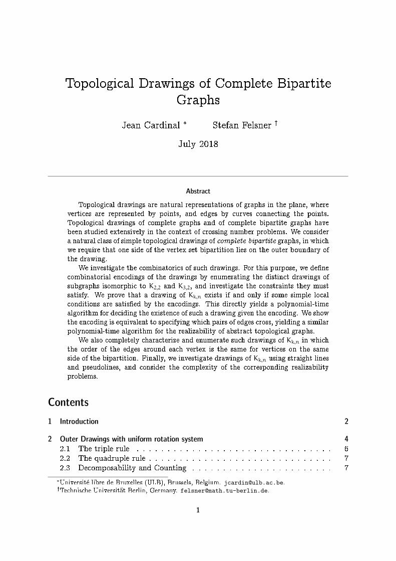
12345 12345
Figure 1: Two outer drawings of K3,5. In each of the two drawings the rotation systemis (12345, 21435, 13254).
around each vertex of V are �xed and identical, they re ect the clockwise order ofp1, . . . , pk on the boundary.
Unlike for complete graphs, the rotation system of an outer drawing of a completebipartite graph does not completely determine which pairs of edges are intersecting.This is exempli�ed with the two drawings in Figure 1.
Results. The paper is organized as follows. In Section 2, we consider outer drawingswith a uniform rotation system, in which the k permutations of the vertices of P areall equal to the identity. In this case, we can state a general structure theorem thatallows us to completely characterize and count outer drawings of arbitrary bipartitegraphs Kk,n.
In Section 3, we consider outer drawings of K2,n with arbitrary rotation systems. Weconsider a natural combinatorial encoding of such drawings, and state two necessaryconsistency conditions involving triples and quadruples of points in V. We show thatthese conditions are also su�cient, yielding a polynomial-time algorithm for checkingconsistency of a drawing.
We also observe that our encoding is equivalent to specifying which pairs of edgesmust intersect in the drawing, hence exactly encodes the corresponding AT-graph.Therefore we show as a corollary that we can decide the realizability of a given AT-graph with underlying graph isomorphic to K2,n in polynomial time.
In Section 4 and 5, we extend these results, �rst to outer drawings of K3,n, thento outer drawings of Kk,n. We prove that simple consistency conditions on triplesand quadruples are su�cient for drawings of Kk,n, yielding again a polynomial-timealgorithm for consistency checking.
In Section 6, we consider outer drawings with the additional property that theedges can be extended into a pseudoline arrangement, which we refer to as extendabledrawings. We give a necessary and su�cient condition for the existence of an extendableouter drawing of a complete bipartite graph given the rotation system. We also touchupon the even more restricted problem of �nding straight-line outer drawings withprescribed rotation systems.
2 Outer Drawings with uniform rotation system
We �rst consider the case where k is arbitrary but the rotation system is uniform,that is, the permutation around each of the k vertices pi is the same. Without loss ofgenerality we assume that this permutation is the identity permutation on [n].
4

In a given outer drawing, each of the n vertices of V splits the plane into k regionsQ1, Q2, . . . , Qk, where each Qi is bounded by the edges from v to pi and pi+1, with theunderstanding that pk+1 = p1. We denote by Qi(v) the ith region de�ned by vertex vand further on call these regions quadrants. We let type(a, b) = i, for a, b 2 V andi 2 [k], whenever a 2 Qi(b). This implies that b 2 Qi(a), see Figure 2. Indeed ifa < b and j 6= i + 1, then edge pi+1b has to intersect all the edges pja, while edgepjb has to avoid pi+1b until they meet in b. It follows that none of the edges pjb canintersect pi+1a. This shows that a 2 Qi(b).
a
b
Q4(a)
Q5(a) Q2(a)
Q3(a)
Q6(a)
Q1(a)
p1
p4
p2
p3p5
p6
Figure 2: Having placed b in Q4(a) the crossing pairs of edges and the order of crossingson each edge is prescribed. In particular a 2 Q4(b). On the right a symmetric outerdrawing of the pair.
Observation 1 (Symmetry). For all a, b 2 V, we have type(a, b) = type(b, a).
For the case k = 2, we have exactly two types of pairs, that we will denote by Aand B. The two types are illustrated on Figure 3. Note that the two types can be dis-tinguished by specifying which are the pairs of intersecting edges. The outer drawingsof K2,n with uniform rotations can be viewed as colored pseudoline arrangements,where:
� each pseudoline is split into two segments of distinct colors,
� no crossing is monochromatic.
a b
b aA B
Figure 3: The two types of pairs for outer drawings of K2,n with uniform rotationsystems.
This is illustrated on Figure 4. The pseudoline of a vertex v 2 V is denoted by `(v).The left (red) and right (blue) parts of this pseudoline are denote by `L(v) and `R(v).Now having type(a, b) = type(b, a) = A means that b lies above `(a) and a liesabove `(b). While having type(a, b) = type(b, a) = B means that b lies below `(a)and a lies below `(b).
5

1
2
3
4
4
3
2
1
1 B B B
2 B A
3 A
4
Figure 4: Drawing K2,4 as a colored pseudoline arrangement. The type of each pair isgiven in the table on the right.
2.1 The triple rule
In what follows, we will say that a < b for a pair a, b 2 V whenever a comes before bin the permutation around the vertices pi.
Lemma 2 (Triple rule). Consider the complete bipartite graph G with vertex biparti-tion (P, V) such that |P| = k and |V | = n, and an outer drawing of G with a uniformrotation system. Then for all a, b, c 2 V such that a < b < c, we have
type(a, c) 2 {type(a, b), type(b, c)}.
Proof. Case k = 2. If type(a, b) 6= type(b, c) there is nothing to show since there areonly two types. Without loss of generality, suppose that type(a, b) = type(b, c) = B.This situation is illustrated in the left part of Figure 5. The pseudoline `(c) must cross`(b) on `R(b), otherwise we would have type(b, c) = A. Hence the point c is on theright of this intersection. Pseudoline `(a) must cross `(b) on `L(b), and a is left of thisintersection. It follows that `(a) and `(c) cross on `R(a) and `L(c), i.e., type(a, c) = B.
a
cb
c a
b
ca
pj
Figure 5: Illustrations for the k = 2 case of Lemma 2 (left), and the k > 2 case ofLemma 2 (right).
Case k > 2. For the general case assume that type(a, b) = i and type(a, c) = j. Ifi = j there is nothing to show. Now suppose i 6= j. From c 2 Qj(a) it follows that pj+1aand pjc are disjoint. Edges pjb and pjc only share the endpoint pj, hence c has to bein the region delimited by pjb and pj+1a, see the right part of Figure 5. This region iscontained in Qj(b), whence type(b, c) = j.
We like to display triples in little tables, e.g., the triple type(a, b) = X, type(a, c) = Y,and type(b, c) = Z is represented as a X Y
b Z
c
.
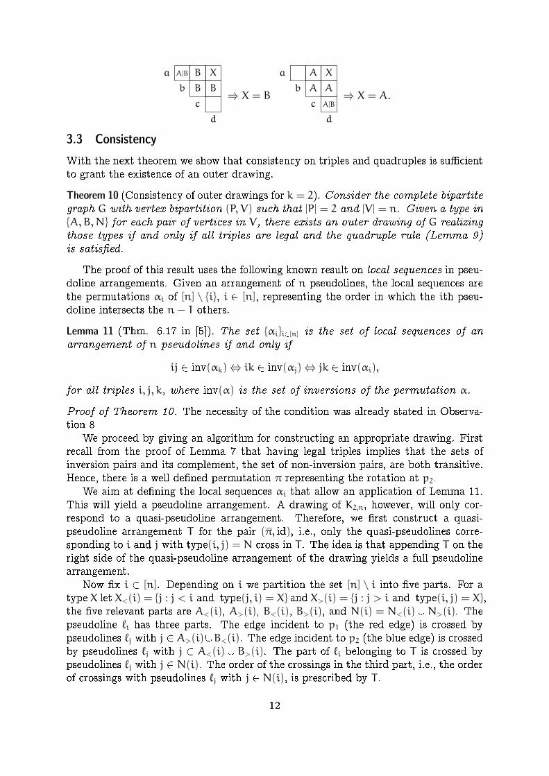
The triple rule can then be depicted as follows:
a X Y
b X
c
⇒ Y = X.
6
2.2 The quadruple rule
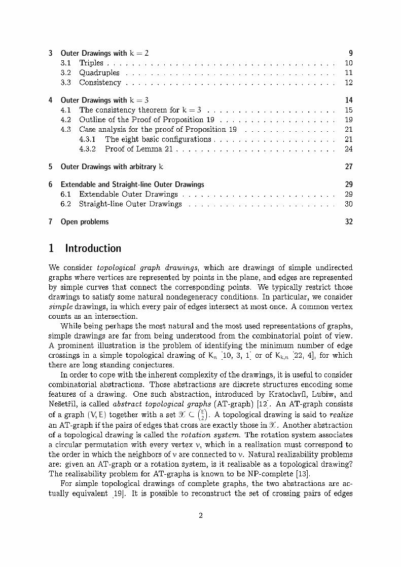
Lemma 3 (Quadruple rule).Consider the complete bipartite graph G with vertex bipartition (P, V) such that|P| = k and |V | = n, and an outer drawing of G with a uniform rotation system.Then for four vertices a, b, c, d 2 V with a < b < c < d, if type(a, c) = type(b, c) =type(b, d) = X then type(a, d) = X, which can be depicted as follows:
a X Y
b X X
c
d
⇒ Y = X.
Proof. Case k = 2. Suppose, without loss of generality, that X = B. Consider thepseudolines representing b and c with their crossing at `R(b)[ `L(c). Coming from theleft the edge `L(d) has to avoid `L(c) and therefore intersects `R(b). On `R(b) the crossingwith `L(c) is left of the crossing with `L(d), see Figure 6. Symmetrically from the rightthe edge `R(a) has to intersect `L(c) and this intersection is left of `R(b) [ `L(c). Toreach the crossings with `L(c) and `R(b) edges `R(a) and `L(d) have to intersect, hence,type(a, d) = B.
a
b
c
d a
b
c
d
Figure 6: Illustration for the k = 2 case of Lemma 3.
Case k > 2. In the general case, we let X = i, and consider the pseudoline arrange-ment de�ned by the two successive vertices pi and pi+1 of P de�ning the quadrants Qi.Proving that type(a, d) = i, that is, that a 2 Qi(d), can be done as above for k = 2 onthe drawing of K2,n induced by {pi, pi+1} and V.
2.3 Decomposability and Counting
We can now state a general structure theorem for all outer drawings of Kk,n with uniformrotation systems.
Theorem 4. Consider the complete bipartite graph G with vertex bipartition (P, V)such that |P| = k and |V | = n. Given a type in [k] for each pair of vertices in V,there exists an outer drawing of G realizing those types with a uniform rotationsystem if and only if:
1. there exists s 2 {2, . . . , n} and X 2 [k] such that type(a, b) = X for all pairsa, b with a < s and b � s, (in the table this corresponds to maximal rectanglewhose cells have all the same entry)
7
2. the same holds recursively when the interval [1, n] is replaced by any of thetwo intervals [1, s− 1] and [s, n].
Proof. (⇒) Let us �rst show that if there exists a drawing, then the types must satisfythe above structure. We proceed by induction on n. Pick the smallest s 2 {2, . . . , n}
such that type(1, b) = type(1, s) for all b � s. Set X := type(1, s). We claim thattype(a, b) = X for all a, b such that 1 � a < s � b � n. For a = 1 this is just thecondition on s. Now let 1 < a.
First suppose that type(1, a) 6= X. We can apply the triple rule on the indices1, a, b. Since type(1, b) 2 {type(1, a), type(a, b)}, we must have that type(a, b) = X.
Now suppose that type(1, a) = X. We have type(1, s − 1) = Y 6= X by de�nition.As in the previous case we obtain type(s− 1, b) = X from the triple rule for 1, s− 1, b.Applying the triple rule on 1, a, s− 1 yields that type(a, s− 1) = Y.
Now apply the quadruple rule on 1, a, s − 1, b. We already know type(1, s − 1) =type(a, s−1) = Y, and by de�nition type(1, b) = X. Hence we must have type(a, b) 6= Y.
Finally, apply the triple rule on a, s − 1, b. We know that type(a, s − 1) = Y,type(s− 1, b) = X. Since type(a, b) 6= Y, we must have type(a, b) = X. This yields theclaim.
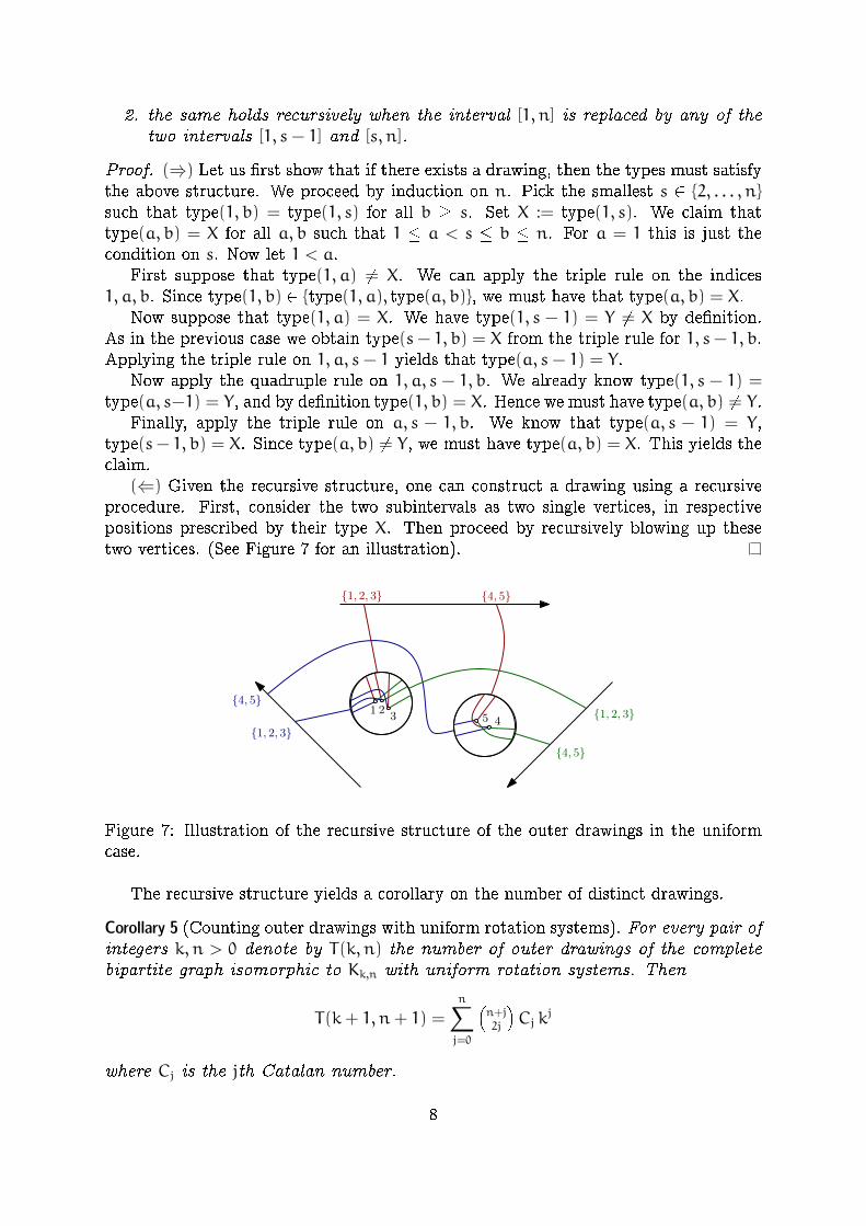
(⇐) Given the recursive structure, one can construct a drawing using a recursiveprocedure. First, consider the two subintervals as two single vertices, in respectivepositions prescribed by their type X. Then proceed by recursively blowing up thesetwo vertices. (See Figure 7 for an illustration).
1 23 45 {1, 2, 3}
{4, 5}{1, 2, 3}
{1, 2, 3}
{4, 5}
{4, 5}
Figure 7: Illustration of the recursive structure of the outer drawings in the uniformcase.
The recursive structure yields a corollary on the number of distinct drawings.
Corollary 5 (Counting outer drawings with uniform rotation systems). For every pair ofintegers k, n > 0 denote by T(k, n) the number of outer drawings of the completebipartite graph isomorphic to Kk,n with uniform rotation systems. Then
T(k+ 1, n+ 1) =n∑j=0
�n+j2j
�Cj k
j
where Cj is the jth Catalan number.
8
Proof. The recursive structure can be modeled in a labeled binary tree. The rootcorresponds to [1, n], the subtrees correspond to the intervals [1, s − 1] and [s, n], andthe label of the root is type(a, b) for a < s � b. The de�nition implies that the labelof the left child of a node is di�erent from the label of the node. Leaves have no label.
For the number T(k, n) of labeled binary trees we therefore get a Catalan-like recur-
sion T(k, n) = k∑n−1
i=1
�k−1kT(k, i)
��T(k, n−i)+T(k, n−1). The factor k preceeding the
sum accounts for the choice of the label for the root. Using symmetry on the labels we�nd that a k−1
kfraction of the candidates for the left subtree comply with the condition
on the labels. The case where the left subtree only consists of a single leaf node isexceptional, in this case there is no label and we have one choice for this subtree, notjust (1− 1/k). This explains the additional summand. The recursion
T(k, n) = T(k, n− 1) + (k− 1)∑n−1
i=1 T(k, i) � T(k, n− i)
together with the initial condition T(k, 1) = 1 yields an array of numbers which is islisted as entry A103209 in the encyclopedia of integer sequences1 (OEIS). The statedexplicite expression for T(k, n) can be found there. It can be veri�ed by induction.
Note that in the case k = 2, Corollary 5 provides a bijection between outer drawingswith uniform rotation systems and combinatorial structures counted by Schr�oder num-bers, such as separable permutations and guillotine partitions. Separable permutationsare permutations that avoid the patterns {2413, 3142}. To make the bijection moreexplicit, we can consider the type matrices as matrices of inversions of a permutation,where the type of a pair of elements is A or B depending on whether the elementsare reversed in the permutation. The triple rule then enforces that the matrix indeedcorresponds to a permutation, while the quadruple rule excludes the two forbiddenpatterns.
3 Outer Drawings with k = 2
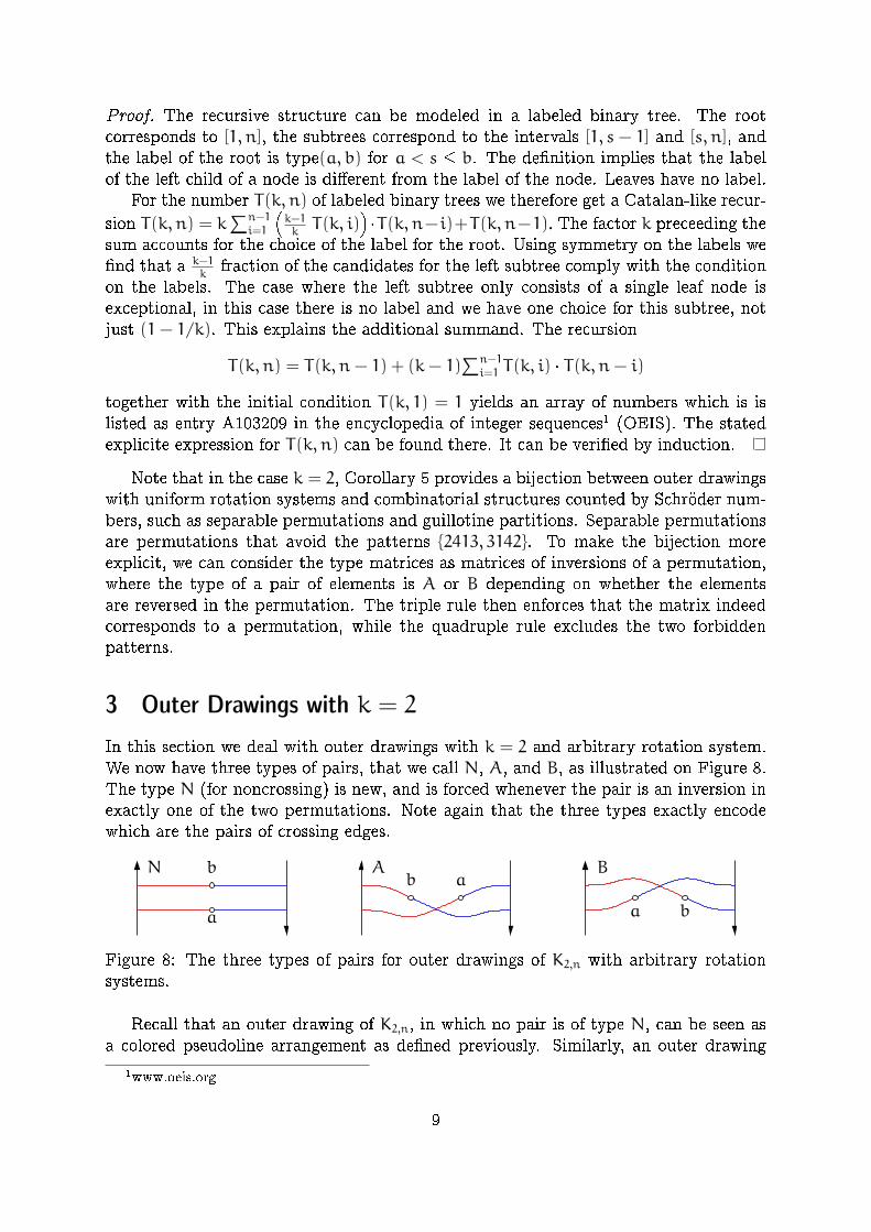
In this section we deal with outer drawings with k = 2 and arbitrary rotation system.We now have three types of pairs, that we call N, A, and B, as illustrated on Figure 8.The type N (for noncrossing) is new, and is forced whenever the pair is an inversion inexactly one of the two permutations. Note again that the three types exactly encodewhich are the pairs of crossing edges.
a b
b a
a
bN A B
Figure 8: The three types of pairs for outer drawings of K2,n with arbitrary rotationsystems.
Recall that an outer drawing of K2,n, in which no pair is of type N, can be seen asa colored pseudoline arrangement as de�ned previously. Similarly, an outer drawing
1www.oeis.org
9
of K2,n in which some pairs are of type N can be seen as an arrangement of coloredmonotone curves crossing pairwise at most once. We will refer to arrangement ofmonotone curves that cross at most once as quasi-pseudoline arrangements. Thepairs of type N correspond to parallel pseudolines. Without loss of generality, we cansuppose that the �rst permutation in the rotation system, that is, the order of thepseudolines on the left side, is the identity. We denote by π the permutation on theright side.
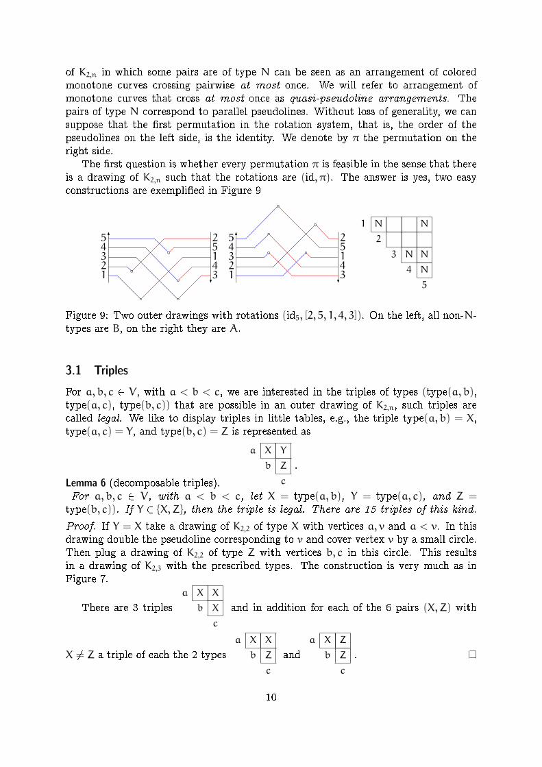
The �rst question is whether every permutation π is feasible in the sense that thereis a drawing of K2,n such that the rotations are (id, π). The answer is yes, two easyconstructions are exempli�ed in Figure 9
34152
341524321
54321
5
1 N N
2
3 N N
4 N
5
Figure 9: Two outer drawings with rotations (id5, [2, 5, 1, 4, 3]). On the left, all non-N-types are B, on the right they are A.
3.1 Triples
For a, b, c 2 V, with a < b < c, we are interested in the triples of types (type(a, b),type(a, c), type(b, c)) that are possible in an outer drawing of K2,n, such triples arecalled legal. We like to display triples in little tables, e.g., the triple type(a, b) = X,type(a, c) = Y, and type(b, c) = Z is represented as
a X Y
b Z
c
.
Lemma 6 (decomposable triples).For a, b, c 2 V, with a < b < c, let X = type(a, b), Y = type(a, c), and Z =type(b, c)). If Y 2 {X,Z}, then the triple is legal. There are 15 triples of this kind.
Proof. If Y = X take a drawing of K2,2 of type X with vertices a, v and a < v. In thisdrawing double the pseudoline corresponding to v and cover vertex v by a small circle.Then plug a drawing of K2,2 of type Z with vertices b, c in this circle. This resultsin a drawing of K2,3 with the prescribed types. The construction is very much as inFigure 7.
There are 3 triples
a X X
b X
c
and in addition for each of the 6 pairs (X,Z) with
X 6= Z a triple of each the 2 types
a X X
b Z
c
and
a X Z
b Z
c
.
10
Note that the triples of the latter lemma are decomposable in the sense of Theorem 4.
Lemma 7.
There are exactly two non-decomposable legal triples:
a N A
b B
c
and
a A B
b N
c
.
Proof. From Lemma 2 we know that triples where all entries are A or B are decom-posable. If type(a, b) = N, then (a, b) is an inversion of π while pairs (a, b) withtype(a, b) 2 {A,B} are non-inversions of π. Both, the set of inversion pairs and the set
of non-inversion pairs are transitive. Hence, triples of typeN
andN
Nwhere
empty cells represent non-inversion pairs are impossible. It remains to consider thecases where exactly one of X and Z is N and the other two symbols in the triple are Aand B. Only the two triples shown in the statement of the lemma remain.
With the two lemmas we have classi�ed all 17 legal triples, i.e., all outer drawingsof K2,3.
Observation 8 (Triple rule).Any three vertices of V must induce one of the 17 legal triples of types.
3.2 Quadruples
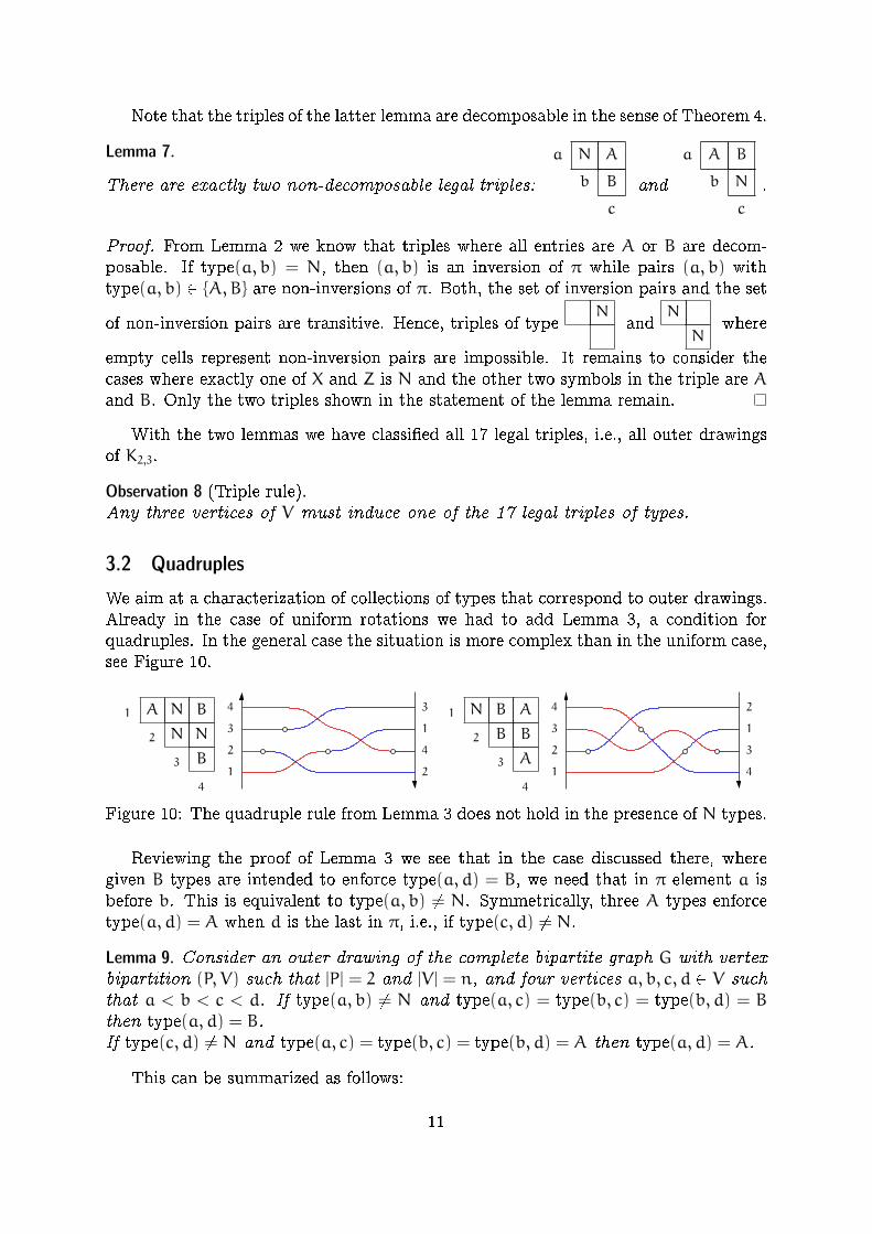
We aim at a characterization of collections of types that correspond to outer drawings.Already in the case of uniform rotations we had to add Lemma 3, a condition forquadruples. In the general case the situation is more complex than in the uniform case,see Figure 10.
4
3
2
1
4
3
2
1
2
3
1
4
3
4
1
2
1 A N B
2 N N
3 B
4
1 N B A
2 B B
3 A
4
Figure 10: The quadruple rule from Lemma 3 does not hold in the presence of N types.
Reviewing the proof of Lemma 3 we see that in the case discussed there, wheregiven B types are intended to enforce type(a, d) = B, we need that in π element a isbefore b. This is equivalent to type(a, b) 6= N. Symmetrically, three A types enforcetype(a, d) = A when d is the last in π, i.e., if type(c, d) 6= N.
Lemma 9. Consider an outer drawing of the complete bipartite graph G with vertexbipartition (P, V) such that |P| = 2 and |V | = n, and four vertices a, b, c, d 2 V suchthat a < b < c < d. If type(a, b) 6= N and type(a, c) = type(b, c) = type(b, d) = B
then type(a, d) = B.If type(c, d) 6= N and type(a, c) = type(b, c) = type(b, d) = A then type(a, d) = A.
This can be summarized as follows:
11
a A|B B X
b B B
c
d
⇒ X = B
a A X
b A A
c A|B
d
⇒ X = A.
3.3 Consistency
With the next theorem we show that consistency on triples and quadruples is su�cientto grant the existence of an outer drawing.
Theorem 10 (Consistency of outer drawings for k = 2). Consider the complete bipartitegraph G with vertex bipartition (P, V) such that |P| = 2 and |V | = n. Given a type in{A,B,N} for each pair of vertices in V, there exists an outer drawing of G realizingthose types if and only if all triples are legal and the quadruple rule (Lemma 9)is satis�ed.
The proof of this result uses the following known result on local sequences in pseu-doline arrangements. Given an arrangement of n pseudolines, the local sequences arethe permutations αi of [n] \ {i}, i 2 [n], representing the order in which the ith pseu-doline intersects the n− 1 others.
Lemma 11 (Thm. 6.17 in [5]). The set {αi}i2[n] is the set of local sequences of anarrangement of n pseudolines if and only if
ij 2 inv(αk) ⇔ ik 2 inv(αj) ⇔ jk 2 inv(αi),
for all triples i, j, k, where inv(α) is the set of inversions of the permutation α.
Proof of Theorem 10. The necessity of the condition was already stated in Observa-tion 8
We proceed by giving an algorithm for constructing an appropriate drawing. Firstrecall from the proof of Lemma 7 that having legal triples implies that the sets ofinversion pairs and its complement, the set of non-inversion pairs, are both transitive.Hence, there is a well de�ned permutation π representing the rotation at p2.
We aim at de�ning the local sequences αi that allow an application of Lemma 11.This will yield a pseudoline arrangement. A drawing of K2,n, however, will only cor-respond to a quasi-pseudoline arrangement. Therefore, we �rst construct a quasi-pseudoline arrangement T for the pair (π, id), i.e., only the quasi-pseudolines corre-sponding to i and j with type(i, j) = N cross in T . The idea is that appending T on theright side of the quasi-pseudoline arrangement of the drawing yields a full pseudolinearrangement.
Now �x i 2 [n]. Depending on i we partition the set [n] \ i into �ve parts. For atype X let X<(i) = {j : j < i and type(j, i) = X} and X>(i) = {j : j > i and type(i, j) = X},the �ve relevant parts are A<(i), A>(i), B<(i), B>(i), and N(i) = N<(i) [N>(i). Thepseudoline `i has three parts. The edge incident to p1 (the red edge) is crossed bypseudolines `j with j 2 A>(i)[B<(i). The edge incident to p2 (the blue edge) is crossedby pseudolines `j with j 2 A<(i) [ B>(i). The part of `i belonging to T is crossed bypseudolines `j with j 2 N(i). The order of the crossings in the third part, i.e., the orderof crossings with pseudolines `j with j 2 N(i), is prescribed by T .
12
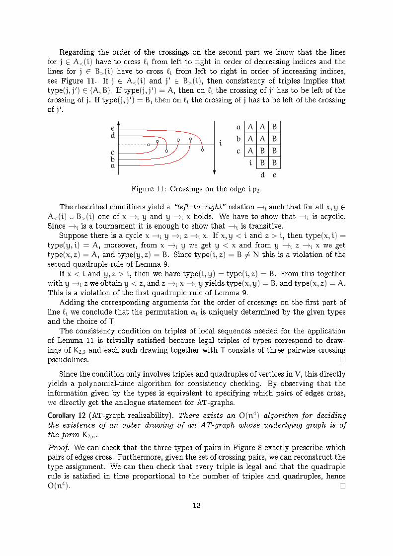
Regarding the order of the crossings on the second part we know that the linesfor j 2 A<(i) have to cross `i from left to right in order of decreasing indices and thelines for j 2 B>(i) have to cross `i from left to right in order of increasing indices,see Figure 11. If j 2 A<(i) and j 0 2 B>(i), then consistency of triples implies thattype(j, j 0) 2 {A,B}. If type(j, j 0) = A, then on `i the crossing of j 0 has to be left of thecrossing of j. If type(j, j 0) = B, then on `i the crossing of j has to be left of the crossingof j 0.
a
b
c
d e
i B B
BBA
A A
A A B
B
a
d
c
e
b
i
Figure 11: Crossings on the edge i p2.
The described conditions yield a \left{to{right" relation →i such that for all x, y 2A<(i) [ B>(i) one of x →i y and y →i x holds. We have to show that →i is acyclic.Since →i is a tournament it is enough to show that →i is transitive.
Suppose there is a cycle x →i y →i z →i x. If x, y < i and z > i, then type(x, i) =type(y, i) = A, moreover, from x →i y we get y < x and from y →i z →i x we gettype(x, z) = A, and type(y, z) = B. Since type(i, z) = B 6= N this is a violation of thesecond quadruple rule of Lemma 9.
If x < i and y, z > i, then we have type(i, y) = type(i, z) = B. From this togetherwith y→i z we obtain y < z, and z→i x→i y yields type(x, y) = B, and type(x, z) = A.This is a violation of the �rst quadruple rule of Lemma 9.
Adding the corresponding arguments for the order of crossings on the �rst part ofline `i we conclude that the permutation αi is uniquely determined by the given typesand the choice of T .
The consistency condition on triples of local sequences needed for the applicationof Lemma 11 is trivially satis�ed because legal triples of types correspond to draw-ings of K2,3 and each such drawing together with T consists of three pairwise crossingpseudolines.
Since the condition only involves triples and quadruples of vertices in V, this directlyyields a polynomial-time algorithm for consistency checking. By observing that theinformation given by the types is equivalent to specifying which pairs of edges cross,we directly get the analogue statement for AT-graphs.
Corollary 12 (AT-graph realizability). There exists an O(n4) algorithm for decidingthe existence of an outer drawing of an AT-graph whose underlying graph is ofthe form K2,n.
Proof. We can check that the three types of pairs in Figure 8 exactly prescribe whichpairs of edges cross. Furthermore, given the set of crossing pairs, we can reconstruct thetype assignment. We can then check that every triple is legal and that the quadruplerule is satis�ed in time proportional to the number of triples and quadruples, henceO(n4).
13
4 Outer Drawings with k = 3
At the beginning of the previous section we have seen that any pair of rotations isfeasible for outer drawings of K2,n. This is not true in the case of k > 2. For k = 4 thesystem of rotations ([1, 2], [2, 1], [1, 2], [2, 1]) is easily seen to be infeasible. In the casek = 3 it is less obvious that infeasible systems of rotations exist. For k = 2 we also hadan e�cient characterization of consistent assignments of types. We generalize this tok = 3.
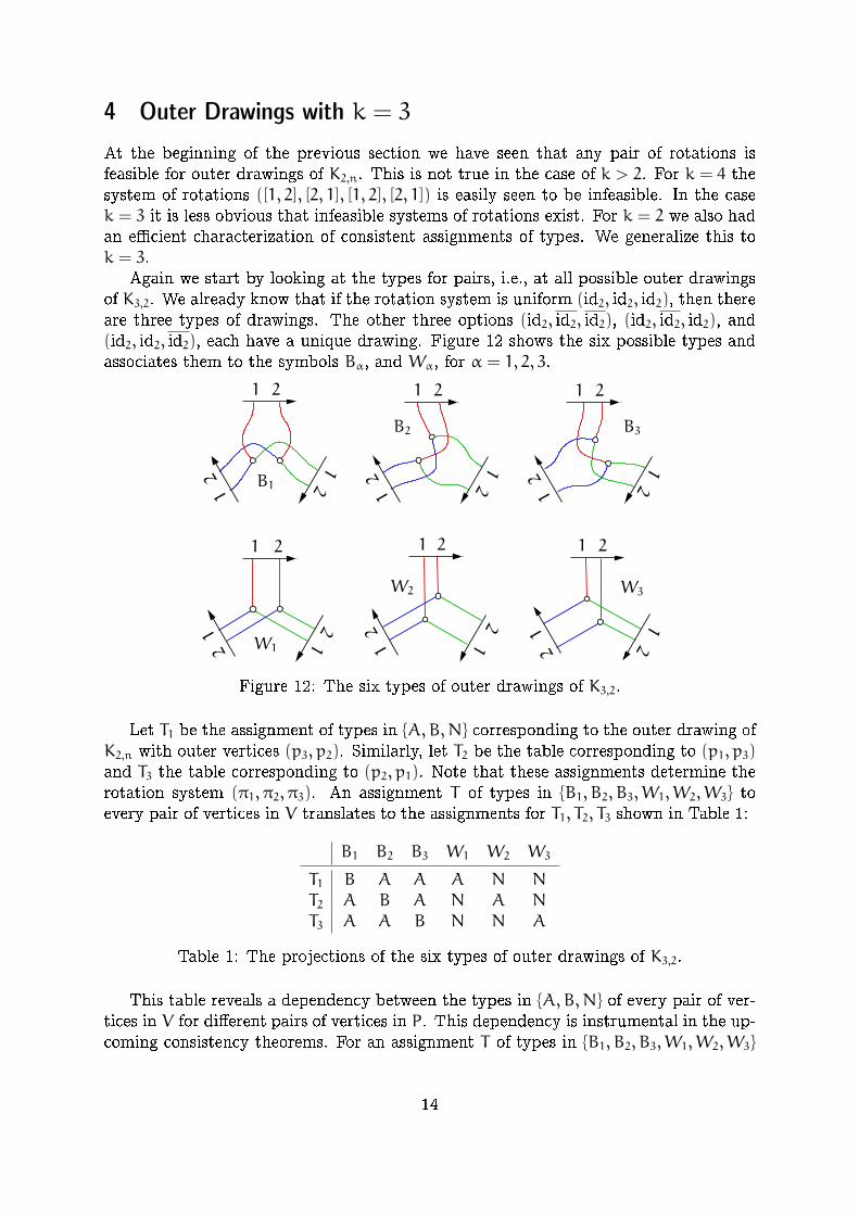
Again we start by looking at the types for pairs, i.e., at all possible outer drawingsof K3,2. We already know that if the rotation system is uniform (id2, id2, id2), then thereare three types of drawings. The other three options (id2, id2, id2), (id2, id2, id2), and(id2, id2, id2), each have a unique drawing. Figure 12 shows the six possible types andassociates them to the symbols Bα, and Wα, for α = 1, 2, 3.
12
12
211
2 12
21
212121
21
12
12
1 21 2
12
12
12
1 2
B1
W1
B2 B3
W2 W3
Figure 12: The six types of outer drawings of K3,2.
Let T1 be the assignment of types in {A,B,N} corresponding to the outer drawing ofK2,n with outer vertices (p3, p2). Similarly, let T2 be the table corresponding to (p1, p3)and T3 the table corresponding to (p2, p1). Note that these assignments determine therotation system (π1, π2, π3). An assignment T of types in {B1, B2, B3,W1,W2,W3} toevery pair of vertices in V translates to the assignments for T1, T2, T3 shown in Table 1:
B1 B2 B3 W1 W2 W3
T1 B A A A N N
T2 A B A N A N
T3 A A B N N A
Table 1: The projections of the six types of outer drawings of K3,2.
This table reveals a dependency between the types in {A,B,N} of every pair of ver-tices in V for di�erent pairs of vertices in P. This dependency is instrumental in the up-coming consistency theorems. For an assignment T of types in {B1, B2, B3,W1,W2,W3}
14
to pairs of vertices in V, we will refer to the induced assignments T1, T2, T3 as the pro-jections of T .
This allows us to analyze the following example.
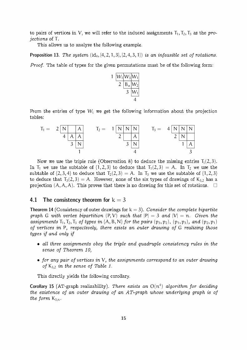
Proposition 13. The system (id4, [4, 2, 1, 3], [2, 4, 3, 1]) is an infeasible set of rotations.
Proof. The table of types for the given permutations must be of the following form:
1 W1W3W1
2 Bα W2
3 W1
4
From the entries of type Wi we get the following information about the projectiontables:
T1 = 2 N A
4 A A
3 N
1
T2 = 1 N N N
2 A
3 N
4
T3 = 4 N N N
2 N
1 A
3
Now we use the triple rule (Observation 8) to deduce the missing entries Ti(2, 3).In T1 we use the subtable of {1, 2, 3} to deduce that T1(2, 3) = A. In T2 we use thesubtable of {2, 3, 4} to deduce that T2(2, 3) = A. In T3 we use the subtable of {1, 2, 3}to deduce that T3(2, 3) = A. However, none of the six types of drawings of K3,2 has aprojection (A,A,A). This proves that there is no drawing for this set of rotations.
4.1 The consistency theorem for k = 3
Theorem 14 (Consistency of outer drawings for k = 3). Consider the complete bipartitegraph G with vertex bipartition (P, V) such that |P| = 3 and |V | = n. Given theassignments T1, T2, T3 of types in {A,B,N} for the pairs (p3, p2), (p1, p3), and (p2, p1)of vertices in P, respectively, there exists an outer drawing of G realizing thosetypes if and only if
� all three assignments obey the triple and quadruple consistency rules in thesense of Theorem 10,
� for any pair of vertices in V, the assignments correspond to an outer drawingof K3,2 in the sense of Table 1.
This directly yields the following corollary.
Corollary 15 (AT-graph realizability). There exists an O(n4) algorithm for decidingthe existence of an outer drawing of an AT-graph whose underlying graph is ofthe form K3,n.
15

Proof. Again, one can check that the three types of pairs in Figure 12 exactly prescribewhich pairs of edges cross, and given the set of crossing pairs, we can reconstruct thetype assignment. We can then check that every triple is legal and that the quadruplerule is satis�ed in time proportional to the number of triples and quadruples, henceO(n4).
Proof of Theorem 14. Let us �rst note that one direction of the Theorem is easy: ifthere exists an outer drawing, then the assignments must be consistent.
We now show that consistency of the type assignments is su�cient for the existenceof an outer drawing. Let T be the assignment of types in {B1, B2, B3,W1,W2,W3} tothe pairs of V given by Table 1, and let (π1, π2, π3) be the corresponding rotations.The consistency of the tables T2 and T3 in the sense of Theorem 10 implies that thereare drawings D2 and D3 of K2,n realizing the type assignments T2 and T3. The vertexp1 (the outer vertex with rotation π1) and its edges form a non-crossing star in bothdrawings.
Let the drawing D2 live on plane Z2 and D3 live on plane Z3 and consider a �xedhomeomorphism φ between the planes. There is a homeomorphism ψ : Z2 → Z2 suchthat mapping D2 via φ � ψ to Z3 yields a superposition of the two drawings with thefollowing properties.
� Corresponding vertices are mapped onto each other.
� The stars of p1 are mapped onto each other, i.e., the edges at p1 of the two drawingsare represented by the same curves.
� At each vertex v 2 V the rotation is correct, i.e., we see the edges to p1, p2, p3 inclockwise order.
� The drawing has no touching edges, i.e., when two edges meet they properly crossin a single point.
The drawing D obtained by superposing D2 and D3 is an outer drawing of K3,n. Wecolor the edges of D as in our �gures, for example the edges incident to p2 are the greenedges. In D each color class of edges is a non-crossing star. For the blue and the greenthis is true because the edges come from only one of D2 and D3. For the red star itis true due to construction. Moreover, all the red-blue and red-green crossings are asprescribed by the original table T . The problem we face is that there is little controlon blue-green crossings. Let ered(v), egreen(v), eblue(v) be the red, green, and blue edgeof v.
Claim: For all v, w the parity of the number of crossings between egreen(v) and eblue(w)in D is prescribed by T , i.e., if T requires a crossing between two edges, then they havean odd number of crossings and an even number of crossings otherwise.
Consider the curves egreen(v)[ered(v) and eblue(w)[ered(w). The rotations prescribewhether the number of intersections of the two curves is odd or even. Hence, the parityis respected by D. The crossings of the pairs (egreen(v), ered(w)), (ered(v), eblue(w)) in Dare as prescribed by T(v,w). Hence, the parity of the number of crossings of egreen(v)and eblue(w) in D is also prescribed. 4
Because the rotation at v in D is correct we also note: If egreen(v) and eblue(v) cross,then the number of crossings is even. Hence, if D has no pair of a green and a blue edgecrossing more than once, then D is an outer drawing realizing the types given by T .
16

Now consider a pair of edges egreen(v) and eblue(w) crossing more than once, v = w isallowed. Use a homeomorphism of the plane to make egreen(v) a horizontal straight linesegment, see Figure 13. (In the literature intersection patterns of two simple curves inthe plane are often called meanders. They are of interest in enumerative and algebraiccombinatorics.)
The intersections with egreen(v) subdivide eblue(w) into a family of arcs and twoextremal pieces. A blue arc de�nes an interval on the green edge, this is the interval ofthe arc. An arc together with its interval enclose a bounded region, this is the regionof the arc.
Fact. Apart from intersecting intervals any two regions of arcs over a �xed green edgeegreen(v) are either disjoint or nested. Because blue edges are pairwise disjoint this alsoholds if the arcs are de�ned by di�erent blue edges.
v
w
Figure 13: A meander with 7 empty lenses.
An inclusionwise minimal region of an arc is a lens. Since D has a �nite number ofcrossings and hence a �nite number of regions we have:
Fact. Every region of an arc contains a lens.
Consider a lens L formed by pair of a green and a blue edge inD. Suppose that L is anempty lens, i.e., there is no vertex u 2 V inside of L. It follows that the boundary of L isonly intersected by red edges, moreover, if a red edge e intersects the boundary of L onthe green side, then e also intersects L on the blue side. Therefore, we can make egreen(v)and eblue(w) switch sides at L and with small deformations at the two crossings get ridof them. It is important to note that the switch at a lens does not change the types.In particular after the switch the drawing still represents assignment T .
Apply switching operations until the drawing D 0 obtained by switching has theproperty that every lens in D 0 contains a vertex.
In the following we show that D 0 has no lens. For the proof we use that the table T1corresponding to (π3, π2) also has to be consistent. Since D 0 has no lens we concludethat it is an outer drawing that realizes the types given by T . The existence of such adrawing was the statement of the theorem.
Let D 0 be a drawing with the property that every lens contains a vertex. Beforegoing into the proof that there is no lens in D 0 we �x some additional notation. For agiven green edge egreen(v) the regions de�ned by blue arcs over egreen(v) can be classi�edas above, below, and wrapping. A wrapping region is a region with one contact betweenegreen(v) and eblue(w) from above and one contact from below.
17

Lemma 16. There is no wrapping region.
Proof. Let R be the wrapping region formed by a blue edge wrapping around egreen(v)and note that v 2 R. If the wrapping blue edge is eblue(v), then ered(v) has to intersectone of egreen(v) and eblue(v) to leave the region. This is not allowed. If the wrappingblue edge is eblue(u) with u 6= v, then eblue(v) has to intersect one of egreen(v) andeblue(u) to leave the region. Again, this is not allowed.
With a similar proof we get:
Lemma 17. Vertex w is not contained in the region de�ned by an arc of eblue(w)over egreen(v).
Proof. The green edge of w would be trapped in such a region.
For a region de�ned by an arc on eblue(w) we speak of a forward or backward regiondepending on the direction of the arc above egreen(v). Formally: label the t crossings ofegreen(v) and eblue(w) as 1, .., t according to the order on eblue(w). Arcs correspond toconsecutive crossings. An arc [i, i+ 1] is forward if crossing i is to the left of crossingi + 1 on egreen(v), otherwise it is backward. The permutation of 1, .., t obtained byreading the crossings from v to p2 along egreen(v) is called the meander permutationand denoted σgreen(v).
A region is a relative lens for egreen(v) and eblue(w) if it is above or below egreen(v)and minimal in the nesting order of regions de�ned by egreen(v) and eblue(w). In thesequel we sometimes abuse notation by talking of lenses when we mean relative lenses.
Proposition 18. For all v 2 V, the green and blue edges of v do not cross in D 0.
Proof. If egreen(v) and eblue(v) cross, then there is at least one blue arcs on eblue(w)over egreen(v) and, hence, there are regions.
From the order of the three outer vertices and the fact that ered(v) has no crossingwith the two other edges of v we conclude that at the last crossing of eblue(v) andegreen(v) the blue edge is crossing egreen(v) downwards.
Since at the �rst crossing the blue edge is crossing upwards there is an arc andconsequently also a lens above egreen(v).
Suppose there is a forward lens above egreen(v). Let u be a vertex in the lens.Vertex u is below the line of v in the green-red arrangement. Hence, either T3(u, v) = Bor T3(u, v) = N and v <1 u. Vertex u is below the forward arc of eblue(v) forming thelens. Hence, it is below the line of v in the red-blue arrangement, and either T2(u, v) = Bor T2(u, v) = N and u <1 v. From Table 1 we infer that the only legal assignment isT(u, v) =W1 and the projections are T2(u, v) = N and T3(u, v) = N. However, there isno consistent choice for the order of u and v in <1. This shows that there is no forwardlens above egreen(v).
Now let [i, i+ 1] be a backward lens above egreen(v). Let u be a vertex in the lens.We distinguish whether the last crossing on the blue edge is to the right/left of the lenson egreen(v), see Figure 14.
Suppose the last crossing k on the blue edge is to the right of the lens, Figure 14(left). To get from the arc [i, i+ 1] to k the edge eblue(v) has to cross egreen(v) upwardsat some crossing j left of i + 1. The edge eblue(u) has to stay disjoint from eblue(v),
18
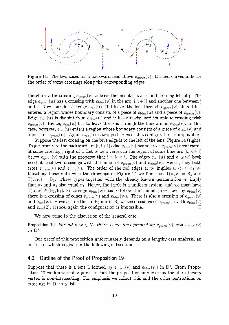
j i kv v iw
u u
j
Figure 14: The two cases for a backward lens above egreen(v). Dashed curves indicatethe order of some crossings along the corresponding edges.
therefore, after crossing egreen(v) to leave the lens it has a second crossing left of j. Theedge egreen(u) has a crossing with eblue(v) in the arc [i, i+1] and another one between jand k. Now consider the edge ered(u). If it leaves the lens through egreen(v), then it hasentered a region whose boundary consists of a piece of eblue(u) and a piece of egreen(v).Edge ered(u) is disjoint from eblue(u) and it has already used its unique crossing withegreen(v). Hence, ered(u) has to leave the lens through the blue arc on eblue(v). In thiscase, however, ered(u) enters a region whose boundary consists of a piece of eblue(v) anda piece of egreen(u). Again ered(u) is trapped. Hence, this con�guration is impossible.
Suppose the last crossing on the blue edge is to the left of the lens, Figure 14 (right).To get from v to the backward arc [i, i+1] edge eblue(v) has to cross egreen(v) downwardsat some crossing j right of i. Let w be a vertex in the region of some blue arc [k, k+ 1]below egreen(v) with the property that j � k < i. The edges ered(u) and ered(w) bothneed at least two crossings with the union of egreen(v) and eblue(v). Hence, they bothcross egreen(v) and eblue(v). The order of the red edges at p1 implies u <1 v <1 w.Matching these data with the drawings of Figure 12 we �nd that T(u, v) = B3 andT(v,w) = B2. These types together with the already known permutation π1 implythat π2 and π3 also equal π1. Hence, the triple is a uniform system, and we must haveT(u,w) 2 {B2, B3}. Since edge eblue(w) has to follow the `tunnel' prescribed by eblue(v)there is a crossing of edges egreen(v) and eblue(w). There is also a crossing of egreen(v)and ered(w). However, neither in B2 nor in B3 we see crossings of egreen(1) with eblue(2)and ered(2). Hence, again the con�guration is impossible.
We now come to the discussion of the general case.
Proposition 19. For all v,w 2 V, there is no lens formed by egreen(v) and eblue(w)in D 0.
Our proof of this proposition unfortunately depends on a lengthy case analysis, anoutline of which is given in the following subsection.
4.2 Outline of the Proof of Proposition 19
Suppose that there is a lens L formed by egreen(v) and eblue(w) in D0. From Propo-
sition 18 we know that v 6= w. In fact the proposition implies that the star of everyvertex is non-intersecting. For emphasis we collect this and the other restrictions oncrossings in D 0 in a list.
19

(1) Edges of the same color do not cross.
(2) Edges of di�erent color that belong to the same vertex do not cross.
(3) Red edges have at most one intersection with any other edge.
These properties will be crucial throughout the argument. We also know that thereare no wrapping regions (Lemma 16) and the vertex in a region or lens is always di�erentfrom the vertices of the edges de�ning the region (Lemma 17).
In section 4.3.1, we discuss eight con�gurations that may appear in a meander ofeblue(w) over egreen(v). The eight con�gurations shown in Figure 15 correspond to thesimplest meanders for the following three binary decisions:
� Vertex w is above/below edge egreen(v).
� The last crossing is to the left/right of the �rst crossing.
� At the last crossing eblue(w) is cutting egreen(v) upward/downward.
For example the meander labeled VII corresponds to below/left/up. In the case dis-cussion we impose additional conditions on vertices u that are contained in the regionsde�ned by arcs of eblue(w) over egreen(v). These conditions either ask for u 2 S1(w) orfor u 62 S1(w). The conditions are so that they are satis�ed for free if the respectiveregions are relative lenses of eblue(w) over egreen(v). In each of the cases we show thatthe T1 projections yield an illegal table. Hence the con�gurations do not appear in thedrawing D 0.
III
V VIII
I II
VI VII
IV
Figure 15: The eight con�gurations for the �rst phase of the case analysis.
In the second part we use the results from the �rst part to show that meanders ofthe drawing D 0 have no in ections, i.e., in the meander permutation we never see i−1and i + 1 on the same side of i. This is split in the following two lemmas. The �rst,easy one, is the following.
Lemma 20. If a meander permutation σgreen(v) has an in ection, then it has one ofthe four turn-back patterns shown in Figure 16.
Proof. Suppose that a meander permutation σ = σgreen(v) has an in ection at i. Wediscuss the case where i + 1 <σ i − 1 <σ i and the blue arc [i + 1, i] of eblue(w) isabove egreen(v). All the other cases can be treated with symmetrical arguments. Firstnote that i − 1 > 1, otherwise, w is in the region de�ned by the arc [i + 1, i]. This isimpossible (Lemma 17).
Now suppose that i − 1 <σ i − 2 <σ i. Let x be a vertex in the region de�ned bythe arc [i − 1, i − 2]. Con�ned by eblue(w) the edge eblue(x) has to cross egreen(v) atleast three times and it contains an arc whose region contains x. This is impossible(Lemma 17). Hence, i+ 1 <σ i− 2 <σ i− 1 <σ i and the meander contains the second
20

of the turn-back patterns shown in Figure 16. Other cases of in ections are related tothe other cases of turn-back patterns.
The proof of the second lemma involves a delicate case analysis and is deferred toSubsection 4.3.2.
Lemma 21. A meander permutation has no turn-back.
TB 1TB 2 TB 4
TB 3
Figure 16: The four turn-back pattern.
The consequence of Lemma 21 is that the meanders in D 0 are very simple, theirmeander permutations are either the identity permutation or the reverse of the identity.In particular every arc de�nes a relative lens. It then follows that each meander in D 0
can be classi�ed according to the three binary decisions mentioned above. Hence, itfalls into one of the con�gurations that have been discussed in Subsection 4.3.1. Theadditional conditions are satis�ed because the arcs all de�ne relative lenses. Hence,there are no nontrivial meanders, i.e., every pair of a green and a blue edge crosses atmost once in D 0. This concludes the proof of Proposition 19.
4.3 Case analysis for the proof of Proposition 19
4.3.1 The eight basic configurations
We now deal with special instances of the con�gurations from Figure 15.
w
v
Figure 17:Illustration for Case I.
Case I. The �rst intersection along eblue(w) is downwardsand the last intersection is upwards and to the right ofthe �rst intersection along egreen(v).
Its last intersection with egreen(v) being upward forceseblue(w) to intersect ered(v) on its �nal piece. Therefore,edge egreen(w) has to turn around v as shown in Figure 17.Now consider ered(w), its �rst crossing (among those rele-vant to the argument) has to be with egreen(v). With thiscrossing, however, ered(w) gets separated from its destina-tion p1 by the union of eblue(w) and egreen(v). Therefore,this case is impossible.
v
w
u
Figure 18:Illustration for Case II.
Case II. The �rst intersection along eblue(w) is upwardsand the last intersection is downwards and to the rightof the �rst along egreen(v) and there is a forward arc ofeblue(w) above egreen(v) whose region contains a vertexu 62 S1(w).
Edge egreen(w) has to turn around v and also ered(w) hasto cross eblue(v), see Figure 19. Now consider a vertex u ina forward region of eblue(w) above egreen(v). Vertex u is not
21

w A B
u A
v
under an arc of eblue(u) (Lemma 17) and there is at mostone crossing of eblue(u) and ered(w). Therefore, eblue(u)behaves as shown in the sketch, i.e., w <3 u <3 v. Alsow <2 u <2 v. From the intersections of green and blueedges we conclude that the projections T1 are as given bythe table on the right. This table is not legal. Hence, thiscase is impossible.
v u
w
Figure 19:Illustration for Case III.
u B A
w N
v
.
Case III. The �rst intersection along eblue(w) is upwardsand the last intersection is downwards and to the left ofthe �rst along egreen(v) and there is a backward arc ofeblue(w) above egreen(v) whose region contains a vertexu 2 S1(w).
Edge egreen(w) has to stay below egreen(v). Now considera vertex u in a backward region of eblue(w) above egreen(v).Vertex u is not under an arc of eblue(u) and we excludethe con�guration of Case I. Therefore, eblue(u) behaves asshown in Figure 18, i.e., u <3 w <3 v. It follows thategreen(u) has to stay above egreen(v) and u <2 v <2 w. Fromthe intersections of green and blue edges we conclude thatthe projections T1 are as given by the table on the right.This tables is not legal. Hence, this case is impossible.
v
u
w
Figure 20:Illustration for Case IV.
v N B
w A
u
.
Case IV. The �rst intersection along eblue(w) is down-wards and the last intersection is upwards and to theleft of the �rst along egreen(v) and there is a backwardarc of eblue(w) below egreen(v) whose region contains avertex u 62 S1(w).
Edge eblue(w) has to cross ered(v) and the other edgesof w have no intersections with edges of v. Edge eblue(u)either turn around w or it crosses ered(v). In the �rst caseegreen(u) has turn around v. Now, ered(u) has to crosseblue(w) and gets separated from its destination p1 by theunion ofeblue(w) and egreen(u). Hence, there is no possi-ble routing for edge ered(u) respecting the restrictions oncrossings in D 0. In the second case eblue(u) crosses ered(v)and v <3 w <3 u. From the green edges we obtain w <2 v <2 u. The intersections ofgreen and blue edges, see Figure 20 imply that the projections T1 are as given by thetable below the �gure. This table is not legal. Hence, this case is impossible.
u
w
v x
Figure 21:Illustration for Case V.
Case V. The �rst intersection along eblue(w) is down-wards and the last intersection is downward and to theright of the �rst. Moreover, along egreen(v) there is aforward arc of eblue(w) below egreen(v) whose region con-tains a vertex u 2 S1(w) and further to the right a for-ward arc of eblue(w) above egreen(v) containing a vertexx 62 S1(w).
22

w A B
x A
u
If u <3 w, then edge eblue(w) makes sure that x 62 S1(u).Therefore, we have Case II with v, u, and x.
If w <3 u <3 v, then w 2 S1(u). Therefore, we have aCase III.
Now let w <3 v <3 u. Since eblue(x) is crossing egreen(v)downwards we have egreen(x) above egreen(v) and a crossingof eblue(w) with egreen(x). Therefore w <3 x.
w
v
u
x
Figure 22:Case V, 2nd illustration.
If w <3 x <3 v, then the intersections of green and blueedges areas shown in Figure 21. The projections T1 aregiven by the table below the �gure. This table is not legal.Hence, this case is impossible. If v <3 x <3 u, then we haveCase IV with x and u. Finally, if u <3 x, then the greenand blue edges behave as shown in Figure 22. Now, ered(w)would have to cross one of eblue(x) and egreen(v) twice toget to its destination p1.
v u
x
w
Figure 23:Illustration for Case VI.
u A B
w A A
v B
x
.
Case VI. The �rst intersection along eblue(w) is down-wards and the last intersection is downward and to theleft of the �rst. Moreover, along egreen(v) there is abackward arc of eblue(w) above egreen(v) whose regioncontains a vertex u 2 S1(w) and further to the righta backward arc of eblue(w) below egreen(v) containing avertex x 62 S1(w).
If x <3 v, then edge eblue(x) either yields a Case II withw 62 S1(x) or a Case III with u 2 S1(x). Therefore, v <3 x.
If w <3 u, then edge eblue(u) has an arc above u or itforms a Case I. Therefore, u <3 w and the complete orderis u <3 w <3 v <3 x.
From green edges we get w <2 v <2 x and u <2 v, seeFigure 23. Independent of the entry T1(u,w) the resultingtable as shown below Figure 23 violates the quadruple rule,Lemma 9. Hence, this case is impossible.
v
w
u
x
Figure 24:Illustration for Case VII.
x A B A
v B B
w u
.
Case VII. The �rst intersection along eblue(w) is upwardsand the last intersection is upward and to the left of the�rst. Along egreen(v) there is a backward arc of eblue(w)below egreen(v) whose region contains a vertex u 62 S1(w)and further to the right a backward arc of eblue(w) aboveegreen(v) containing a vertex x 2 S1(w).
If v <3 x, then edge eblue(x) either yields a Case I or aCase IV with u 62 S1(x). Therefore, x <3 v.
If u <3 x, then vertices v, u and x are in the con�g-uration of Case II. If x <3 u <3 w, then u <3 v sinceotherwise u would be in a region of eblue(u), a violationof Lemma 17. Now u <3 v <3 w and T1(u, v) = B,T1(u,w) = A and T1(v,w) = B is an illegal table.
23

If v <3 u, then x <3 v <3 w <3 u and the situation is as sketched in Figure 24.Irrespective of u <2 w or w <2 u the T1 projections of the remaining 5 pairs yieldthe partial table shown below the �gure. This violates the quadruple rule, Lemma 9.Hence, this case is impossible.
v
w
u
x
Figure 25:Illustration for Case VIII.
u A N��B A
v B B
x w
.
Case VIII. The �rst intersection along eblue(w) is up-wards and the last intersection is upward and to theright of the �rst. Along egreen(v) there is a forward arcof eblue(w) above egreen(v) whose region contains a ver-tex u 62 S1(w) and further to the right a forward arc ofeblue(w) below egreen(v) containing a vertex x 2 S1(w).
If v <3 u, then edge eblue(u) either yields a Case I or aCase IV with w 62 S1(x). Therefore, u <3 v.
If u <3 x <3 v, then edge eblue(x) yields a Case III withu 2 S1(x). If x <3 u, then x <3 u <3 w and T1(x, u) = N,T1(x,w) = B and T1(u,w) = A is an illegal table.
Therefore, v <3 x and in total u <3 v <3 x <3 w, seeFigure 25. Also u <2 v <2 w and v <2 x only the order of xand w in <2 is not determined. If w <2 x then T1(x,w) = N otherwise T1(x,w) = B.The resulting table is shown below Figure 25. In the �rst case the triple u, v, x yields anillegal subtable. In the second case there is a violation of the quadruple rule, Lemma 9.Hence, this case is impossible.
4.3.2 Proof of Lemma 21
Given v suppose that some eblue(w) has a meander over egreen(v) with a turn-back.Among all the turn-backs over egreen(v) choose the one with the turn-back point i asfar as possible, where i is the crossing of the turn-back whose two adjacent crossingsare on the same side.
It will be seen in the proof that this speci�c choice of turn-back substantially sim-pli�es the analysis of two of the cases.
Case TB 1. The turn back corresponds to a substring i, i − 1, i − 2, i + 1 or to asubstring i, i+ 1, i+ 2, i− 1 in σgreen(v) and the turn-back arc is above egreen(v).
Let us assume that the substring is i, i − 1, i − 2, i + 1 so that the turn-back arc is[i, i − 1]. Let u be a vertex in the region of the turn-back arc and let x be a vertex inthe region of the arc [i− 1, i− 2].
The edge eblue(u) is con�ned by eblue(w) and has a forward arc below x. If eblue(u)has a crossing with ered(v) then we have a Case I. From Lemma 17 it follows that thelast crossing of eblue(u) and egreen(v) is downwards and to the right of i+ 1.
If x 62 S1(u), then eblue(u) has a backward arc a in the interval [i − 1, i − 2] suchthat x is in the region of arc a. The left part of Figure 26 shows a schematic view ofthe situation. Let y be a vertex in the region of an arc of eblue(u) above egreen(v) andpreceeding a along eblue(u) such that y 62 S1(x). Edges eblue(u) and Lemma 17 forceeblue(x) to have its last intersection with egreen(v) downwards and to the right of i+ 1.Hence eblue(x) and y are in the con�guration of Case II.
24
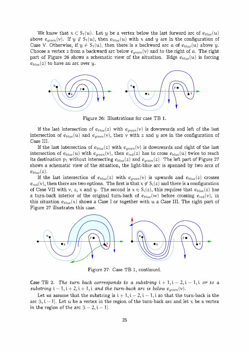
We know that x 2 S1(u). Let y be a vertex below the last forward arc of eblue(u)above egreen(v). If y 62 S1(u), then eblue(u) with x and y are in the con�guration ofCase V. Otherwise, if y 2 S1(u), then there is a backward arc a of eblue(u) above y.Choose a vertex z from a backward arc below egreen(v) and to the right of a. The rightpart of Figure 26 shows a schematic view of the situation. Edge eblue(u) is forcingeblue(z) to have an arc over y.
u
x
u
x
yy
z
Figure 26: Illustrations for case TB 1.
If the last intersection of eblue(z) with egreen(v) is downwards and left of the lastintersection of eblue(u) and egreen(v), then v with z and y are in the con�guration ofCase III.
If the last intersection of eblue(z) with egreen(v) is downwards and right of the lastintersection of eblue(u) with egreen(v), then ered(z) has to cross eblue(u) twice to reachits destination p1 without intersecting eblue(z) and egreen(z). The left part of Figure 27shows a schematic view of the situation, the light-blue arc is spanned by two arcs ofeblue(z).
If the last intersection of eblue(z) with egreen(v) is upwards and eblue(z) crossesered(v), then there are two options. The �rst is that x 62 Si(z) and there is a con�gurationof Case VII with v, z, x and y. The second is x 2 Si(z), this requires that eblue(z) hasa turn-back interior of the original turn-back of eblue(w) before crossing ered(v), inthis situation eblue(x) shows a Case I or together with u a Case III. The right part ofFigure 27 illustrates this case.
u
x
y
z
u
x
y
z
Figure 27: Case TB 1, continued.
Case TB 2. The turn back corresponds to a substring i + 1, i − 2, i − 1, i or to asubstring i− 1, i+ 2, i+ 1, i and the turn-back arc is below egreen(v).
Let us assume that the substring is i + 1, i − 2, i − 1, i so that the turn-back is thearc [i, i− 1]. Let u be a vertex in the region of the turn-back arc and let x be a vertexin the region of the arc [i− 2, i− 1].
25

The �rst intersection of eblue(u) with egreen(v) is left of the turn back point i of themeander eblue(w). The choice of the turn-back as the leftmost implies that eblue(u) hasno turn-back. Hence, σgreen(u) is the reverse of the identity.
If the last intersection of eblue(u) with egreen(v) is downwards, then this is a Case IIIwith x. Otherwise the last intersection is upwards and eblue(u) intersects ered(v). Thenthere is a backward arc of eblue(u) below egreen(v) and a vertex y from such an arctogether with x shows that the situation of Case VII. See Figure 28.
x
u
y
Figure 28: Illustrations for case TB 2.
Case TB 3. The turn back corresponds to a substring i + 1, i − 2, i − 1, i or to asubstring i− 1, i+ 2, i+ 1, i and the turn-back arc is above egreen(v).
Let us assume that the substring is i + 1, i − 2, i − 1, i so that the turn-back is thearc [i, i− 1]. Let u be a vertex in the region of the turn-back arc and let x be a vertexin the region of the arc [i− 2, i− 1].
The �rst intersection of eblue(u) with egreen(v) is left of the turn back point i of themeander eblue(w). The choice of the turn-back as the leftmost implies that eblue(u) hasno turn-back. Hence, σgreen(u) is the reverse of the identity.
If eblue(u) intersects ered(v), then with x this yields a Case IV. Otherwise there isa backward arc of eblue(u) above egreen(v). Let y be a vertex from such an arc. Noweblue(u) together with x and y are a Case VI.
Case TB 4. The turn back corresponds to a substring i, i − 1, i − 2, i + 1 or to asubstring i, i+ 1, i+ 2, i− 1 and the turn-back arc is below egreen(v).
Let us assume that the substring is i, i − 1, i − 2, i + 1 so that the turn-back is thearc [i, i− 1]. Let u be a vertex in the region of the turn-back arc and let x be a vertexin the region of the arc [i− 2, i− 1].
If eblue(x) intersects ered(v) this is a Case I. It follows that that x <2 v. If u <3 xthen u and x are in the con�guration of Case II.
If x <3 u, then there is a forward arc of eblue(u) below egreen(v) and to the right ofi− 2. Let y be a vertex from the region of such an arc.
We �rst consider the case y 2 S1(u). If eblue(u) intersects ered(v) then u with yyields a Case VIII. If x <3 y, then it follows with Lemma 17 that x 2 S1(y) so that theyform a Case III. For y <3 x edge eblue(y) has to turn back as shown in the left part ofFigure 29. In this con�guration ered(u) has to cross one of egreen(v) and eblue(y) twiceto get to its destination p1.
Now we are in the case x <3 u and y 2 S1(u). This requires a backward arc ofeblue(u) whose region contains y. To the right of this arc there has to be a backwardarc above egreen(v). Let z be a vertex from the region of this arc. The situation isshown in the right part of Figure 29. If y <3 x, then z 62 S1(y) so that y and z form aCase II. If x <3 y, then either y is a Case I or it forms a Case III with x.
26

y
u u
xx
y
z
Figure 29: Illustrations for case TB 4.
5 Outer Drawings with arbitrary k
We now generalize our result on consistency of outer drawings for k = 2, 3 to any k � 2.In the previous section, we de�ned types for each pair of vertices in V in an outer
drawing of K3,n. Fortunately, we do not need to go beyond the enumeration of the outerdrawings of K3,2 to be able to generalize our result to arbitrary values of k.
Theorem 22 (Consistency of outer drawings for k � 2). Consider the complete bipar-tite graph G with vertex bipartition (P, V) such that |P| = k and |V | = n. Givenassignments Tij of types in {A,B,N} for each pair of vertices (pi, pj) in P and eachpair of vertices in V, there exists an outer drawing of G realizing those types ifand only if
� all assignments Tij for 1 � i < j � k obey the triple and quadruple consistencyrules in the sense of Theorem 10,
� for any triple of vertices from P and and each pair of vertices in V theassignments correspond to an outer drawing of K3,2 in the sense of Table 1.
Proof. We proceed by induction, suppose that the result holds for some k and provethat the result holds for k+ 1. The base cases for k = 2, 3 were proved in the previoussections.
From the induction hypothesis, there exists a drawing Dk−1 of Kk−1,n realizing thetypes involving vertices p1, p2, . . . , pk−1 in P. Similarly, there exists a drawing Dk ofK2,n realizing the types involving the two vertices p1 and pk.
Similarly to what we did in the proof of Theorem 14, we can superpose the twodrawings in such a way that the drawings of the two stars K1,n corresponding to p1match. More precisely, let the drawing Dk−1 live on plane Zk−1 and Dk live on planeZk. Consider a �xed homeomorphism φ between the planes. There is a homeomorphismψ : Zk−1 → Zk−1 such that mapping Dk−1 via φ �ψ to Zk yields a superposition of thetwo drawings with the following properties:
� Corresponding vertices are mapped onto each other.
� The stars of p1 are mapped onto each other, i.e., the edges at p1 of the two drawingsare represented by the same curves.
� At each vertex v 2 V the rotation is correct, i.e., we see the edges to p1, p2, . . . , pkin clockwise order.
� The drawing has no touching edges, i.e., when two edges meet they properly crossin a single point.
27
The drawing D obtained by superposing Dk−1 and Dk is a drawing of Kk,n, possiblywith some multiple crossings. We color the edges of D according to the vertex pi 2 Pit is incident to, using colors 1, 2, . . . , k. Each color class of edges is a non-crossingstar, and the parity of the number of crossings between two edges of distinct colors isprescribed by the type assignments. Furthermore, since Dk−1 and Dk are proper outerdrawings, all pairs of edges crossing more than once have respective colors i and k forsome i 2 {2, 3, . . . , k− 1}.
Consider all lenses formed by an edge of color k and another edge of color i 2{2, 3, . . . , k − 1}. Such a lens is said to be empty whenever it does not contain anyvertex from V. It is inclusionwise minimal whenever it does not fully contain any otherlens. Consider an empty inclusionwise minimal lens formed by an edge ek(v) of color kand another edge ei(w) of color i.
If an edge of color i 0 2 {1, 2, 3, . . . , k − 1} \ {i} intersects the lens, it can only crossei(w) once. Similarly, it cannot cross the boundary of the lens on ek(v) more than once,either because i 0 = 1, or because otherwise the lens would not be minimal. Anotheredge of color k cannot intersect the lens, because it could only do so by intersectingei(w) at least twice, contradicting the minimality of the lens.
Hence all edges intersecting the lens intersect its boundary exactly once on eachedge. Therefore we can safely get rid of the two crossings by making ek(v) and ei(w)switch sides. The switch at a lens does not change the type assignment. We canperform this iteratively until no empty lens is remaining. We call the �nal drawing D 0.This drawing has the property that every lens contains a vertex.
We now wish to show that D 0 has no lens. For the sake of contradiction, supposethat there is a lens formed by ei(v) and ek(w) in D
0. We can apply our previous analysisfor the case k = 3 on the restriction D 00 of D 0 formed by the edges of color 1, i, and k,letting red= 1, green= i, and blue= k. In particular Proposition 19 holds, and D 00 hasno lens. Therefore, neither does D 0, which is a suitable outer drawing of Kk,n.
This yields the following corollary for AT-graphs.
Corollary 23 (AT-graph realizability). There exists an O(k3n2 + k2n4) algorithm fordeciding the existence of an outer drawing of an AT-graph whose underlying graphis of the form Kk,n.
Proof. We know that the three types of pairs A,B,N (see Figure 12) exactly prescribewhich pairs of edges cross, hence given the set of crossing pairs, we can reconstruct thetype assignments Tij. From these data, we can consider every 5-tuple (pa, pb, pc, u, v),with pa, pb, pc 2 P and u, v 2 V, and check that the corresponding drawing of theinduced K3,2 graph is one of the drawings given in Table 1. This can be done in timeO(k3n2). If this is correct, we can then check that every triple is legal and that thequadruple rule is satis�ed for each Tij. This can be done in time O(k2n4), hence theresult.
In fact, this implies that checking consistency on all 6-tuples of vertices is su�cient.This matches the result of Kyn�cl for complete graphs [15].
28

6 Extendable and Straight-line Outer Drawings
A simple topological drawing of a graph is called extendable if its edges can be ex-tended into a pseudoline arrangement. We consider the problem of the existence ofan extendable outer drawing for a given rotation system. We also further restrict tostraight-line drawings. We exploit a connection between topological drawings and gen-eralized con�gurations of points which was also used by Kyn�cl [15]. The main resultuses the notion of suballowable sequence, as de�ned by Asinowski [2].
6.1 Extendable Outer Drawings
We will use the notion of allowable sequence. These sequences were introduced byGoodman and Pollack in a series of papers [7, 8, 9] as an abstraction of the sequencesof successive permutations obtained by projecting a set of n points in R2 on a rotatingline. A good summary of this and related notions can be found in article PseudolineArrangements in the Handbook of Discrete and Computational Geometry [6]. Werestrict to simple allowable sequences, corresponding to point sets with no three pointson a line and such that no two pair of points determine the same slope.
A sequence π1, π2, . . . , πm+1, . . . , π2m of permutations of an n-element set, with m =
(n2), is an allowable sequence if for all i 2 [m], πi and πm+i are reverse of each other,each consecutive pair of permutations di�er only by a single adjacent transposition,and every pair of element is reversed exactly twice in the sequence.
We will also need the following additional de�nition: a generalized con�gurationis a pair (C,A) such that C is a collection of n points in the projective plane P2 andA is an arrangement of pseudolines, one of which is the pseudoline at in�nity L∞,satisfying the following conditions:
� every pair of points of C lie on a pseudoline of A,
� each pseudoline in A contains exactly two points of C, except L∞,� L∞ does not contain any point of C.
We say that an allowable sequence on an n-element set is realized by a generalizedcon�guration on n points when the successive permutations of the sequence correspondto successive segments of the pseudoline L∞, and the transposition between a pair ofpermutations corresponds to the intersection of L∞ with the pseudoline containing thetwo corresponding points. In particular, we observe that if a permutation π is realizedat some point p 2 L∞, then p can be connected by additional pseudolines to the nother points in the radial order prescribed by π.
The following result is known.
Theorem 24 (Goodman and Pollack [8], Thm. 4.4). Every allowable sequence can berealized by a generalized con�guration.
This directly yields that allowable sequences exactly encode which are the achiev-able rotation systems for our drawings. We �rst de�ne suballowable sequences, seeAsinowski [2]: A sequence π1, π2, . . . , πk of permutations of an n-element set is said to be
29

a suballowable sequence if there exists an allowable sequence admitting π1, π2, . . . , πkas a subsequence.
Theorem 25. Given a sequence π1, π2, . . . , πk of permutations of n elements, thereexists an extendable outer drawing of Kk,n with this rotation system if and only ifπ1, π2, . . . , πk is a suballowabe sequence.
Proof. First, suppose that the rotation system is a suballowable sequence. Then byde�nition there exists an allowable sequence admitting it as a subsequence. Then fromTheorem 24 there exists a generalized con�guration on n points realizing this sequence.The n points form the set V . For each permutation πi, there exists a point on L∞ thatcan be connected by additional pseudolines to the n points of V in the order prescribedby πi. These k points form the set P. By keeping only the inner segments of thepseudolines connecting every point of P with all points of V, we obtain an extendableouter drawing satisfying our conditions.
Now suppose there exists an extendable outer drawing. Consider the generalizedcon�guration obtained as follows. First, we extend the edges between the points of Pand V into pseudolines, which is possible from the extendability of the drawing. Thenwe connect the points of P by the pseudoline at in�nity. Finally, by iteratively applyingLevi's enlargement Lemma, we can also connect every pair of points in V by a newpseudoline. The order in which each point of P is connected to all points of V realizesone permutation in the allowable sequence de�ned by the generalized con�guration.The collection of such permutations therefore forms a suballowable sequence.
Note that since suballowable sequences can be recognized e�ciently (see [2]), thisdirectly yields a polynomial-time algorithm for deciding whether there exists an ex-tendable outer drawing realizing a given rotation system.
6.2 Straight-line Outer Drawings
We have a direct equivalent statement for straight-line outer drawings.
Theorem 26. Given a sequence π1, π2, . . . , πk of permutations of n elements, thereexists a straight-line outer drawing of Kk,n with this rotation system if and onlyif π1, π2, . . . , πk is a suballowable sequence that can be realized by an actual pointarrangement.
This does not yield an e�cient algorithm, since deciding whether a given allowablesequence can be realized by an arrangement of straight lines is a hard problem [21,18, 11]. The problem, however, is tractable in the special case where k = 3. Thisis due to the fact that we can �x the orientation of the three sets of edges. Thereare two cases to consider. If the suballowable sequence π1, π2, π3 can be extendedinto an allowable sequence such that the three permutations πi appear in the �rst mpermutations of the whole sequence, then there exists a straight-line outer drawingwith p1 = (−∞,∞), p2 = (0,∞), and p3 = (∞,∞). This corresponds to the case wherethe three projection directions span less than a half-circle. Otherwise there exists adrawing with p1 = (∞,∞), p2 = (0,−∞) and p3 = (−∞, 0).
30
We �rst give an example showing that there are rotation systems for k = 3 that aresuballowable sequences but do not admit a straight line outer drawing. Up to renaming,this example is the same as Asinowski's example of nonrealizable suballowable sequence([2], Proposition 8). We give the proof for completeness. Furthermore, our proofdirectly indicates how to solve the straight-line realizability problem in the case k = 3.
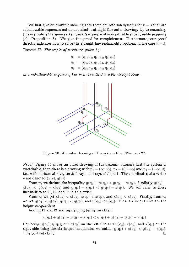
Theorem 27. The triple of rotations given by:
π1 = (q1, q6, q5, q2, q3, q4)
π2 = (q3, q2, q1, q4, q5, q6)
π3 = (q5, q4, q3, q6, q1, q2)
is a suballowable sequence, but is not realizable with straight lines.
q1
q4
q5
q6
q3q2
Figure 30: An outer drawing of the system from Theorem 27.
Proof. Figure 30 shows an outer drawing of the system. Suppose that the system isstretchable, then there is a drawing with p1 = (∞,∞), p2 = (0,−∞) and p3 = (−∞, 0),i.e., with horizontal rays, vertical rays, and rays of slope 1. The coordinates of a vertexv are denoted (x(v), y(v)).
From π1 we deduce the inequality y(q6) − x(q6) < y(q1) − x(q1). Similarly y(q2) −x(q2) < y(q5) − x(q5) and y(q4) − x(q4) < y(q3) − x(q3). We will refer to theseinequalities as I1, I2, and I3 in this order.
From π2 we get x(q6) < x(q5), x(q4) < x(q1), and x(q2) < x(q3). Finally, from π3we get y(q1) < y(q2), y(q3) < y(q6), and y(q5) < y(q4). These six inequalities are thehelper inequalities.
Adding I1 and I2 and rearranging terms we obtain
y(q6) + y(q4) + x(q1) + x(q3) < y(q1) + y(q3) + x(q6) + x(q4)
Replacing y(q6), y(q4), and x(q3) on the left side and y(q3), x(q6), and x(q4) on theright side using the six helper inequalities we obtain y(q5) + x(q2) < y(q2) + x(q5).This contradicts I3.
31
A straight line outer drawing of such a rotation system can be regarded as a tropicalarrangement of lines. We refer to [17] for an introduction to tropical geometry. Suchouter drawings can consequently be regarded as tropical arrangements of pseudolines.Restated as a result in tropical geometry Theorem 27 tells us that there are non-stretchable tropical arrangements of pseudolines.
The classical construction of a simple non-stretchable example of pseudolines dueto Ringel is based on the 9 lines of a Pappus con�guration. In [20] tropical versionsof Pappus are discussed. They note that a con�guration on 9 tropical lines which canbe obtained from the con�guration of Theorem 27 by replacing points q` by tripleincidences of lines ai, bj, ck with {i, j, k} = {1, 2, 3} is a valid tropical version of Pappus'Theorem.
The stretchability problem for a tropical arrangements of pseudolines is polynomial-time solvable, as it boils down to the feasibility of a linear program. The proof ofTheorem 27 indicates how to set up such a linear program.
7 Open problems
A problem that remains for k = 2 is to �nd a good description of all outer drawingsfor a given pair (π1, π2) of rotations. We state the same problem di�erently:
Problem 1. For a given pair (π1, π2) of permutations characterize all consistentassignments of types with the property that if a < b in both permutations, thentype(a, b) 2 {A,B}, and if a <1 b and b <2 a, then type(a, b) = N.
The simpler case where π1 = π2 (hence all types are in {A,B}) is covered by Corol-lary 5, which provides a bijection with combinatorial structures counted by Schr�odernumbers. The following natural question also remains unsolved:
Problem 2. For a given triple (π1, π2, π3) of rotations, can we decide in polynomialtime whether there exists a consistent assignment of types?
The problem could be generalized to arbitrary k: how hard is it to decide whetherthere exists an outer drawing of Kk,n for a given rotation system? We answered thisquestion partially, by showing that it is polynomial-time decidable when the drawingis further required to be extendable.
We also note that outer drawings are not really enlightening with respect to cross-ing numbers, as minimally crossing outer drawings of Kk,n are easy to describe. Itcan be checked that by drawing the n vertices of V on a line so that bk/2c verticesof P see them in some order, and the other dk/2e vertices see them in the reversedorder, we achieve the minimum number of crossings. This minimum has value exactly
(n2)�(k2) − bk/2cdk/2e
�. Further insight into crossing numbers could be gained by con-
sidering the obvious remaining problem of generalizing our analysis to general simpletopological drawings, dropping the outer property.
32

Acknowledgments
This work was started at the Workshop on Order Types, Rotation Systems, andGood Drawings in Strobl am Wolfgangsee (Austria) in 2015. We thank the organizersfrom TU Graz as well as the participants for fruitful discussions. Special thanks go toPedro Ramos who suggested to look at complete bipartite graphs.
S. Felsner also acknowledges support from DFG grant Fe 340/11-1.
References
[1] B. M. �Abrego, O. Aichholzer, S. Fern�andez-Merchant, P. Ramos, and
G. Salazar, The 2-page crossing number of Kn, Discrete & ComputationalGeometry, 49 (2013), 747{777.
[2] A. Asinowski, Suballowable sequences and geometric permutations, DiscreteMathematics, 308 (2008), 4745{4762.
[3] J. Bla�zek and M. Koman, A minimal problem concerning complete planegraphs, in M. Fiedler, editor: Theory of graphs and its applications, Czech. Acad.of Sci., 1964, 113{117.
[4] R. Christian, R. B. Richter, and G. Salazar, Zarankiewicz's conjecture is�nite for each �xed m, J. Comb. Theory, Ser. B, 103 (2013), 237{247.
[5] S. Felsner, Geometric Graphs and Arrangements, Advanced Lectures in Math-ematics, Vieweg Verlag, 2004.
[6] S. Felsner and J. E. Goodman, Pseudoline Arrangements, in Handbook ofDiscrete and Computational Geometry, Toth, O'Rourke, and Goodman, eds., CRCPress, 3 ed., 2018.
[7] J. E. Goodman and R. Pollack, On the combinatorial classi�cation of non-degenerate con�gurations in the plane, J. Comb. Theory, Ser. A, 29 (1980),220{235.
[8] J. E. Goodman and R. Pollack, Semispaces of con�gurations, cell complexesof arrangements, J. Comb. Theory, Ser. A, 37 (1984), 257{293.
[9] J. E. Goodman and R. Pollack, The complexity of point con�gurations,Discrete Applied Mathematics, 31 (1991), 167{180.
[10] F. Harary and A. Hill, On the number of crossings in a complete graph,Proc. Edinburgh Math. Soc., 13 (1963), 333{338.
[11] U. Hoffmann, Intersection Graphs and Geometric Objects in the Plane, PhDthesis, TU Berlin, 2016.
[12] J. Kratochv��l, A. Lubiw, and J. Ne�set�ril, Noncrossing subgraphs in topo-logical layouts, SIAM J. Discrete Math., 4 (1991), 223{244.
33

[13] J. Kratochv��l and J. Matou�sek, NP-hardness results for intersectiongraphs, Commentationes Math. Univ. Carol., 30 (1989), 761{773.
[14] J. Kyn�cl, Simple realizability of complete abstract topological graphs in P,Discrete & Computational Geometry, 45 (2011), 383{399.
[15] J. Kyn�cl, Improved enumeration of simple topological graphs, Discrete & Com-putational Geometry, 50 (2013), 727{770.
[16] J. Kyn�cl, Simple realizability of complete abstract topological graphs simpli-�ed, in Proc. Graph Drawing and Network Visualization, vol. 9411 of LNCS, 2015,309{320.
[17] D. Maclagan and B. Sturmfels, Introduction to tropical geometry, vol. 161of Graduate Studies in Mathematics, AMS, 2015.
[18] N. E. Mn�ev, The universality theorems on the classi�cation problem of con�g-uration varieties and convex polytopes varieties, in Topology and geometry|-Rohlin Seminar, vol. 1346 of LNM, Springer, 1988, 527{543.
[19] J. Pach and G. T�oth, How many ways can one draw a graph?, Combinatorica,26 (2006), 559{576.
[20] J. Richter-Gebert, B. Sturmfels, and T. Theobald, First steps in tropi-cal geometry, in Idempotent mathematics and mathematical physics, vol. 377 ofContemp. Math., AMS, 2005, 289{317.
[21] P. W. Shor, Stretchability of pseudolines is NP-hard, in Applied geometry anddiscrete mathematics, vol. 4 of DIMACS, AMS, 1991, 531{554.
[22] K. Zarankiewicz, On a problem of P. Tur�an concerning graphs, FundamentaMathematicae, 41 (1954), 137{145.
34