topic: advances in wastewater treatment by combined...
TRANSCRIPT

Topic: Advances in wastewater treatment by combined
microbial fuel cell-membrane bioreactor (MFC-MBR)
Sreemoyee Ghosh Ray
Gourav Dhar Bhowmick
Prof. Makarand M. Ghangrekar
Prof. Arunabha Mitra
13th IWA Specialized Conference
on Small Water and Wastewater
Systems
5th IWA Specialized Conference
on Resources-Oriented Sanitation

Commonly Used Aerobic Biological Wastewater Treatment Processes
• Aerobic respiration pathway
• Bio-oxidation
• Nitrification
Wastewater
BODNH4
O2
Attached growth process
CO2
NO3
Oxygen transfer limitation
Suspended growth process
Better treatment
efficiency
2
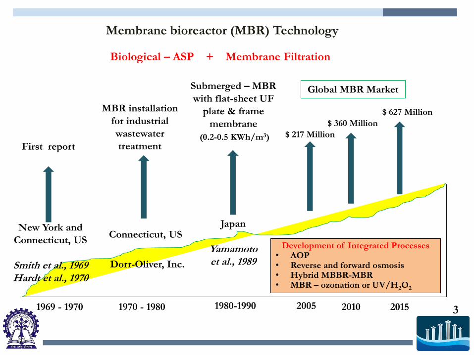
Membrane bioreactor (MBR) Technology
Biological – ASP + Membrane Filtration
1969 - 1970 1970 - 1980 1980-1990
First report
MBR installation
for industrial
wastewater
treatment
Submerged – MBR
with flat-sheet UF
plate & frame
membrane
Connecticut, US
20152005 2010
Global MBR Market
$ 217 Million
$ 360 Million
$ 627 Million
New York and
Connecticut, US
Smith et al., 1969Hardt et al., 1970
Dorr-Oliver, Inc.
Japan
Yamamoto et al., 1989
Development of Integrated Processes• AOP• Reverse and forward osmosis• Hybrid MBBR-MBR• MBR – ozonation or UV/H2O2
3
(0.2-0.5 KWh/m3)

MBR technology involves high energy-consuming process
Energy consumption of MBR can be lowered by integrating it with
Microbial Fuel Cell (MFC) technology
R
H+
H+
½ O2 + 2H+ + 2e-
H2O
8e- 8e-
CH3COO -
+ 4H2O
2HCO3-
+ 9H +
Anode Cathode
(E0ox= - 0.187 V)
(E0red= 0.805 V)
CEM
Microbial Fuel Cell (MFC)
Conversion of bio-chemical
energy to electrical energy
Bio-electricity – An Alternative
and Clean Energy
• How much electrical energy can be
generated?
• Can we provide an efficient treatment?
• Can low-cost sustainable development of
MFC-MBR technology be achieved?
4

Recent advances in MFC-MBR processes
Completely
anaerobic process
• Electrochemical – MBR
• Up-flow integrated air-cathode
MFC-MBR
Wang, 2013 – Sci. Rep.Ge, 2013 – J. Chem. Technol. Biotechnol.Wang, 2012 – Appl. Energy
Wang, 2013 – Chem. Eng. Technol.
Combination of
anaerobic –
aerobic processMFC – Biocathode MBR Wang, 2014 – Bioresour. Technol.
Consumption of electrical energy
to develop MFC-based biosensors
Lower energy consumption
5

Aim of our research
Development of two-stage continuous process of
combining MFC with MBR treatment technology for a
highly-efficient and reliable wastewater treatment
6
• For treatment of organic wastewater, having COD of 3 g/l
• To achieve better treatment efficiency in terms of organic
matter removal
• Recovery of high quality reusable effluent

Reactor fabrication and operating principle
Parameters Operating conditions
Working volume 1.5 l
Electrodematerial
Anode Cathode
Carbon felt (untreated)C/TiO2 suspension
Inoculum Mixed anaerobic sewage sludge
Substrate Synthetic wastewater –Sucrose as carbon source Jadhav & Ghangrekar, 2009 (Bioresour. Technol.)
Substrate conc. 3 g COD/l
HRT 2 days
MFC
Parameters Operating conditions
Working volume 1 l
MLSS 7.09 ± 0.48 g/l
F/M 0.08 kg COD/kg MLSS. day
HRT 10 h
Inoculum Aerobic pond sediment
Substrate MFC effluent
Membrane filtration
Hollow-fibre Polysulfone-made UF membrane (pore size 80 nm, OD 1 mm and ID 0.8 mm)
Membrane area 300 cm2 /l
Permeate flux 38 l/m2.h
Aerobic MBR
Electrochemical monitoring,
polarization study and
determination of coulombic
efficiency (Logan, 2008 – John
Wiley & Sons Inc. )
Total and soluble COD, MLSS,
MLVSS, TKN and alkalinity (APHA 1998)
6

Feed
bucket
Feed
Pump
Digital
multimeter
MBR
Vacuum Pump
UF
Filtration
assembly
Clear
effluent
Two-stage wastewater treatment process combining microbial fuel cell
and aerobic membrane bioreactor –
Bench-scale working model
UF Membrane
MFC
7

Results..
Generation of bio-electricity in MFC
Parameters Responses
Open circuit potential 536 ± 25 mV
Working potential (100 Ω) 260 ± 12 mV
Power density 1.021 W/m3
Internal resistance (Whole cell)
17.8 Ω
CE 4.35 %
Polarization and power curves for MFC
Treatment of wastewater in MFC
The COD removal efficiency of 78.4 ± 2.14 %
was observed during MFC treatment. The total
COD concentration of MFC effluent was 0.71
± 0.04 g/l.
8

Treatment of MFC-effluent in MBR with submerged UF membrane
Characteristics of effluent at different stages of MFC-MBR treatment
Parameters
Wastewater (MFC
reactor influent)
MFC reactor
effluent
MBR effluent
(Permeate)
Total COD 3.02 (0.03) 0.71 (0.04) -
Soluble COD 2.65 (0.02) 0.59 (0.03) 0.04 (0.003)
TKN 0.31 (0.05) 0.147 (0.02) 0.010
TS 3.67 (0.05) 5.09 (0.08) -
TSS - - < 0.005
MLVSS NA 0.9 (0.02) ND
pH 7.53 (0.14) 7.31 (0.11) 7.4 (0.1)
Soluble COD, TKN and SS removal efficiency was 98.49 ± 0.28 %, 96.77
± 0.12 % and 99.75 ± 0.18 %, respectively.
Organic removal efficiency in combined MFC-MBR process
a All units are in g/L, except pH; numbers in the parenthesis are standard deviation
NA= Not applicable: ND= Not detectable
9

Analysis of Bio-kinetic Parameters of MBR
10

Kinetic Equations and Results
Monod equation for biomass growth rate: 𝝁 = 𝝁𝒎𝑺
𝑲𝒔+𝑺
The rate of change of biomass in MBR: 𝑽.𝒅𝑿
𝒅𝒕= 𝝁𝑿𝑽 − 𝒌𝒅. 𝑿𝑽 − 𝑸𝒘𝑿 − 𝑸𝑬𝑿𝑬
At steady state condition, dX/dt= 0: 𝝁 = 𝒌𝒅 +𝑸𝒘
𝑽+
𝑸𝑬
𝑽.𝑿𝑬
𝑿
Sludge retention time, 𝑆𝑅𝑇 (𝜽𝒄) =𝑽𝑿
𝑸𝒘𝑿 + 𝑸𝑬𝑿𝑬
Hence, 𝝁 = 𝒌𝒅 +𝟏
𝑺𝑹𝑻
Thus, the final equation for substrate utilization: 𝑺 =𝑲𝒔
𝟏
𝑺𝑹𝑻+𝒌𝒅
𝝁𝒎− 𝒌𝒅+𝟏
𝑺𝑹𝑻
The substrate balance
equation to demonstrate the expression for biomass generation in MBR:
𝑿 =𝑸(𝑺𝟎−𝑺)−𝑺𝑬.𝑸𝑬
𝒌𝒅+𝟏
𝑺𝑹𝑻
𝒀
𝑽
• The SRT was calculated as 15 days.
• Endogenous decay constant (kd) and sludge-yield coefficient (Y) was calculated
as 0.07 d-1 and 0.216 g VSS/g of COD, respectively. 11

Summary..• How much electrical energy can be generated?
Authors Anode CathodeMaximum power
density (W/m3)
Wang, 2013 (Water Res.) Graphite rod Stainless steel mesh 1.43
Ge, 2013 (Sci. Rep.) Carbon
brush
Carbon cloth coated
with 10% Platinum
(Pt)
2
Li, 2014 (J. Chem. Technol.
Biotechnol.)
Carbon cloth Carbon cloth coated
with 10% Pt0.15
Liu, 2014 (Int. J. Hydrogen
Energy)
Graphite
granules
Stainless steel mesh0.15
Li, 2014 (Sep. Purif. Technol.) Graphite
granules
Polyester filter cloth,
modified by in situ
formed PANi
(polyaniline)-phytic
acid (PA)
0.78
This Study Carbon felt C/TiO2 ink cathode1.02
12

• Can we provide an efficient treatment?
The treated effluent generated in two-stage combined MFC-MBR process has the
following characteristics:
• Can low-cost sustainable development of MFC-MBR technology be achieved?
Soluble COD: In the range of 30 – 40 mg/l
BOD: Less than 5 mg/l
TKN: 10 mg/l
TSS: Less than 5 mg/l
1. Generation of high quality effluent – Membrane retains most particulate
matter.
2. Combined process has smaller footprint for medium-scale organic wastewater
treatment.
3. Easy operation and less space is required for reactor set-up
13

Acknowledgement
Thank You